1
owners
a
a
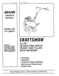
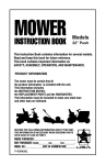
Model No.
502.2541
52
11 P. LECTRIC START
8 SPEED = 30" MOWER
EA ENG!
I
CAUTION:
Read And Follow
All Safety Rules
And Instructions
Operating
Equipment.
This
Before
® Assembly
® Operation
• Maintenance
o Repair and Adjustment
® Repair Parts
F-88516
Sears, Roebuck and Co., Chicago, IL. 60684
U.S.A.
• PrTnted fn U,S,A.
SAFETY RULES
Safe Operation Practices for Riding Vehicles
As Recommended by American National Standards Institute
17, The vehicle and attachments must be stopped and inspected
1.
Know the controls and how to stop quickly, READ THIS
for damage after striking a foreign object, All damage must
INSTRUCTION BOOK and any instructions furnished with
attachments.
be repaired before restarting and operating the equipment.
2.
Do not allow children to operate the machine. Do not allow
18, Do not change the engine governorsettings oroverspeed the
adults to operate tt without proper instruction.
engine.
3,
Clear the work area of objects (wire, rocks, etc.) which might
19. When using the vehicle with a mower, proceed as follows:
be discharged by the machine,
a. Mow only in daylight or tn good a_ifieiat light2
4.
Handle gasoline with care, It is highly flammable.
b, Never make a cutting height adjustment while the
a. Use an approved gasoline container.
engine is running if the operator must dismount.
b. Never remove the fuel cap or add gasoline to a running
c. Stop the engine before removing a grass catcher or
orhot engine oran engine that has not been allowed to cool
unclogging the chute,
for several minutes after running, Never fill the fuel tank
d. Check the blade(s) and mounting nut(s) for proper tightindoors. Clean up spilled gasoline.
ness at frequent intervals, Frequently check the blade for
wear or damage such as cracks and nicks, A blade that is
c. Do not run the engine indoors. Exhaust fumes are
bent or damaged must be immediately replaced with a
dangerous,
factory replacement blade. For safety, replace the blade
5.
Always wear safety glasses or a eye shield when you operate
the unit to protect your eyes from foreign objects that can be
every two years, Frequently check the nut(s) that hold the
thrown from the unit, Always wear eye protection when you
blade(s). Replace damaged nuts and tighten loose nuts,
,'
make an adjustment or repairs to the unit.
20.
Disengage power to the mower before backing up. Do not
6.
Keep all nuts, bolts, and screws tight to be sure the equipmow in reverse unless absolutely necessary and then only
after careful observation of the entire area behind the
ment is in safe working condition.
mower.
7,
Disengage all attachment clutches and shift into neutral
before attempting to start the engine,
21. Under normal usage, the grass catcher bag material" is
8.
Disengage power attachment(s) when transporting or not
subject to deterioration and wear. It should be checked
in use.
frequently for bag replacement. Replacement bags should be
9,
Do not stop or start suddenly when going uphil] or downhill,
checked to ensure compliance with the original manufacMow up and down the face of steep slopes; never across the
turers recommendations or specifications.
face, See the "Guide" in the back this book to check for
22. Do not operate the mowerwithout either the grass catcher or
safe operation,
guards in place, Read the instructions provided with the
1O, Reduce speed and exercise extreme caution on slopes and in
grass catcher.
sharp turns to prevent tipping or loss of control. Be especially
23,
Do not carry passengers, Do not mow when children and
cautious when changing directions on slopes.
others are present.
11, Stay alert for holes, rocks, roots in the terrain, and other
24.
Never store the equipment with gasoline in the tank inside a
hidden hazards, Keep away from drop-offs,
building where fumes may reach an open flame or spark.
12. Use care when pulling loads or using heavy equipment.
Allow the engine to cool before storing in any enclosure.
a. Use only approved drawbar hitch points.
25. Take atl possible precautions when leaving the vehicle
b. Limit loads to those you can safety control.
unattended, such as disengaging the blade engagement _
c, Do not turn sharply. Use care when baektng,
control lever, lowering the attachment(s), shifting into neutral,
d, Use counterweight(s) or wheel weights when suggested
setting the parking brake, stopping the engine, and removing
in the instruction book.
the key.
13. Watch out for traffic when crossing or near roadways.
26,
Keep the vehicle and attachments in good operating condi14. When using any atiachments, never direct discharge of
tion, and keep safety devices in place and working,
material toward bystanders or allow anyone near the unit
27.
Disengage power to attachment(s) and stop the engine
while in operation.
before making any repairs or adjustments, The carburetor
15. Disengage power to attachment(s) and stop the engine
can be adjusted with the engine running.
before 1eaving the operator's position.
28, Wa!!; for all movement to stop before servicing any part of the
16. To reduce fire hazards, keep the engine free of grass, leaves,
29, ;:;Read and follow the instructions in this book concern ng
or excessive grease.
safety, and op§ration of the mower.
WARNING: This unit is equipped with an internal combustion engine and must not be used on or near any unimproved forest-covered,
brush-covered or grass-covered land unless the engine's exhaust system is equipped with a spark arrester meeting applicable local or state
laws (if any), If a spark arrester is used, it must be maintained in effect!re working order by the operator,
In the State of California the above is required by law (Section 4442 of the California Public Resources Code), Other states may have similar
laws, Federal laws apply on federal lands, See an Authorized Service Center for a spark attester for the muffler,
precautions. It means: "Attentionl
Become Alertl
Look for this symbol to point out important safety
Your Safety Is Involved/p
F-88516
This product is made to give you many hours of performance and
safe operation. To keep the unit in good condition, you must
correctly service the unit. For safety and performance, follow the
ASSEMBLY, OPERATION, and MAINTENANCE instructions. If you
can not correct a problem, see the nearest Sears Service Center.
CUSTOMER
RIDER FEATURES
Craftsman
ignition.
Air cooled and long life with solid state
Engine
All Gear Transmission
Eight forward speeds and one reverse
to let you select the correct speed for your type of yard. A drive
chain connects the transmission to an automotive type
differential.
RESPONSIBILITIES
Follow all the assembly instructions. Correctly adjust the unit.
Carefully read and foltow the rules for safe operation. Inspect the
unit, Complete all maintenance on the unit, Know how to operate
all standard and accessory equipment on the unit, Make sure that
the operator can correctly operate the unit. Operate the unit only
with guards, shields, and other safety items in place and working
correctly. Service the unit only with authorized or approved
replacement parts,
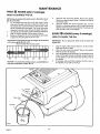
RIDING LAWN
REAR ENGINE
Tilt Seat
The seat tilts forward for easy access to the battery
and the engine,
Side Panels
The side panels can be easily removed for access
to the engine. •
Mower Housing
The full-floating suspension and single blade
give an even cut. The lift lever has an eight position height
adjustment.
MOWER
ATTACHMENTS
Record in the space below the serial number and the date
of purchase of this unit.
The model number and serial number are found under the
seat on a plate attached to the seat support.
This unit can use attachments available at the nearest Sears Store.
This unit can pull attachments like a lawn sweeper, a lawn aerator,
or a hopper spreader, This unit can not use attachments that
engage the ground like a plow, a disk harrow, or a cultivator.
Serial Number:
MAINTENANCE
Date of Purchase:
A Sears Maintenance Agreement Is available on this unit. See the
nearest Sears Store for information.
AGREEMENT
Keep these numbers for future reference,
LIMITED
TWO YEAR WARRANTY
ON ELECTRIC START
RIDING
EQUIPMENT
For two years from the date of purchase,when thisriding equipment is maintained, lubricated, and tuned up accordingto the operating
and maintenance instructions in the Owner's Manual, Sears will repair free of charge any defect in material or workmanship in this
electric start riding equipment.
Thiswarranty excludesblade(s), blade adapter(s}, sparkplug(s), air cleaner, and belt(s),which are expendable and become worn during
normal use.
This warranty does not cover:
- tire replacement or repair caused by punctures from outside objects (such as nails, thorns, stumps, or glass); and
- repairs necessary because of operator abuse or negligence, including the failure to maintain the equipment according to
instructions contained in the Owner's Manual; and
- riding equipment used for commercial or rental purposes.
FULL
90-DAY
WARRANTY
ON BATTERY
For 90 days from the date of purchase, if any battery included with this riding equiPment proves defective in material or workmanship
and our testing determines the battery will not hold a charge, Sears will replace th_ battery at no charge,
WARRANTY SERVICE IS AVAILABLE BY CONTACTING THE NEAREST SEARS SERVICE CENTEP_'DEPARTMENT IN THE UNITED
STATES. This warranty applies only while this product is in use in the United States.
This warranty gives you specific legal rights, and you may also have other rights which vary from state to state.
Sears, Roebuck and Co,, D/698-731A, Sears Tower, Chicago, tL
F-88516
60684
3
INDEX
S
A
Adjustments:
Blade Engagement Control .............. 15
Brake, Drive ......................................... 25
Carburetor ...........................................29
Chain, Front Drive ..............................26
Chain, Rear Drive ...............................27
Mower Housing, Level ...................... 22
Throttle Control Cable ....................... 29
Assembly ..........................................5 - 10
Attachments ...............................................3
Filter, Air ................................................... t 9
Fuel ............................................................12
Fuel System, Storage ............................. 30
Fuse ..................._................................ 32, 33
B
Maintenance .................................. t3 - 19
Air Filter ................................................19
Battery .................................................. 18
Blade ............................................. 16, 17
Blade Engagement Control .............. 15
Drive Brake ..........................................25
Drive Chains ................................. 26, 27
Engine Oil ..................................... 14, 19
Lubrication .......................................... 18
Muffler
Check ...................................................18
Spark Arrester ................................ 2, 18
Spark Plug ................................................ 18
Tires ...........................................................17
Mower Housing
Level .....................................................22
Remove and Install ............................20
Battery:
Charge ....................................................7
Clean and Check ................................ 18
Emergency Start ................................ 30
Install .................................................... 10
Storage ................................................30
Belt;
Motion Drive, Replace ....................... 21
Mower Drive, Adjust .......................... 15
Mower Drive, Replace ....................... 21
Blade, Remove and Install ..................... 16
Blade, Sharpen ......................................... 17
Blade Engagement Control'.
Adjust ...................................................15
Operation ............................................. 11
Brake Pedal, Operation ........................... 11
Lubrication ................................................ 18
M
O
C
Oil:
Carburetor, Adjust ...................................29
Chains, Check and Adjust ............... 26, 27
Charge Battery ...........................................7
Clutch/Brake Pedal
11
Controls ..............................................11, 1'2
Engine:
Carburetor ........................................... 29
Oil, Change .................................. 14, t9
Oil Level, Check .................................. 14
Oil, Type ...............................................14
Operation Speed Chart ..................... I2
Starting ................................................12
Stopping ..............................................12
Storage ................................................30
Throttle Control ........................... 11, 29
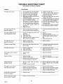
Trouble Shooting Chart .................... 31
F-88516
Check ...................................................14
Change .................................................19
Operation .......................................11 - 13
Mower Housing .................................. 13
Operate On Hills ................................. 13
Operate The Unit ................................ t3
Start Engine ........................................ t2
Stop The Unit ..................................... 12
P
Parts Bag
"
6
R
Repair and Adjustment ................ 20 - 30
Mower Drive Belt ............................... 22
Carburetor ...........................................29
Drive Chains .................................26, 27
Level Mower Housing ....................... 22
Motion Drive Belt ............................... 21
Mower Housing, Install ..................... 20
Mower Housing, Remove ................. 20
4
Safety Rules ................................................ 2
Seat ..........................................., .................. 9
Sharpen, Blade ......................................... 17
Shift Lever ................................................ 12
Side Panel, Remove ................................ 13
Slope Guide ..........;................................... 51
Spark Plug ................................................ 18
Speed Control Chart ............................... 12
Start Engine .............................................. 12
Steering Wheel ..........................................8
Stop, Riding Mower ................................ 12
Storage ......................................................30
T
Throttle Control Cable, Adjust .............. 29
Tire Pressure ..................................... 10, 17
Transmission, Friction Drive ......... 23 - 28
Trouble Shooting Chart .......................... 31
W
Warranty ...................................................... 3
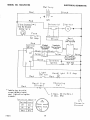
Wiring Schematic .................................... 32
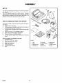
ASSEMBLY
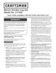
SET UP
12
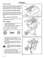
Your unit was carefully inspected and put in a carton for protection
from damage.
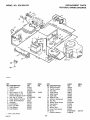
The unit is assembled except for the items shown on this page.
These items are in the carton with a bag of fasteners and loose
parts needed for assembly. Find and remove these items, The
fasteners and roose parts are shown on the next page.
HOW
TO REMOVE
11
FROM THE CARTON
To remove the riding mower from the carton, follow the instructions below.
I.
Open the top of the carton,
2.
The items shown at the right are in a small box. Remove and
check each item. Remove the small box.
3.
Cut each corner of the carton from the top to the bottom with
a knife.
4.
Move the shift lever to the NEUTRAL position.
5.
Make sure the parking brake is disengaged,
6.
Move the lift lever to the HIGH position,
7.
Carefully push the riding mower backwards off the wood
frame,
TOOLS YOU NEED TO ASSEMBLE THE UNIT
I.
Adjustable wrench
2.
Open end wrench 1/2" - 9/16"
3.
Open end wrench 7/16"- 1/2"
4,
Blade type screwdriver
5,
Phillips screwdriver
6.
Low Tire pressure gauge
7.
Knife
F-88516
D-4656-2
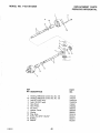
I. Seat
2. Bezel
3, Steering VVhee|
4. Steering Post
5
" 5. Parts Bag
6. Owner's Manual
7. Battery
8, Battery Tray
9. Battery Acid
10. Bellows
11. Upper Console
12. Cover
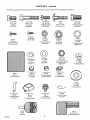
PARTS
The fasteners
and loose parts are shown
(4) Hex Bolt
5/16" x 5/8"
For Seat
STD523106
beiow.
The fasteners
(1) Hex Bolt
5/16" x 1-1/2"
For Adapter
STD5231 t5
26x161
(2) Screw
#10xl/2" Type BT
For Console Cover
are shown
full size with the quantities
(2) Hex Bolt
1/4" -20 x 5/8"
For Battery Cables
STD522506
5/16" x 1-1/4"
For Steering Post
For Steering Wheel
STD523707
@
For Bearing
STD611005
(2) Locknut
I/4"-20
(1) Locknut
5/16"- 18
For Battery Cables
STD541425
For Adapter
STD541431
24582
(4) Hub Cap
For Wheels
().
(I) Hex Bolt
3/8" x 3/4"
15x66
Not shown full size
in brackets
6x90
(1) Bolt
(2) Screw
(4) Lockwasher
I,D, 5116"
For Seat
STD551131
55804
(1) Cover
For Battery Clamp
BAG - contents
(4) Washer
I,D. 1 !/3Z _
For Seat
STD551031
Not shown
fullsize
20107
(2) Seat Spring Cap
For Seat Springs
(2) Locknut
5/16"-18
For Steering Post (1)
For Batter/Clamp
(1)
STD54I 431
19x39
(1) Lockwasher
I.D.3/8"
For Steering Wheel
STD551237
Notsi_Own
futI size
20094Z
(1) Washer
I.D. 13/32"
For Steering Wheel
Not shown ful! size
56022
(1) Bearing
For Steering Post "
t 7xl 32
(t) Washer
I,D, .328"
For Steering Post
Not shown full size
Not shown
fuilsize
Not shown
Not shown
full size
55705
55253Z
55919
55911
(1) Tube, Oll Drain
(1 } Clamp, Battery
For Battery
(I) Cap
For Steering Wheel
(I} Adapter
For Steering WheeI
For Engine
91275
(2) Key
For Ignition
F-88516
futl size
54148
(t) Cable Cover
For Red Battery Cable
ASSEMBLY
HOW TO PREPARE AND
CHARGE THE BATTERY
Remove and discard
the metal tape, ,
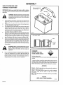
IMPORTANT: Before you install the battery, add the battery
acid, (Electrolyte) to the battery, Battery acid wilt damage paint
and parts,
WARNING: Read the instructions included with
the battery acid container, Protect your hands
and eyes from the battery acid. Use clothing that
will protect you,
I.
2.
3.
4.
5.
If not Tnstalledon the battery, remove the vent capsfrom the
plastic bag, Read the instructions included with the vent
caps,
If medal tape covers the vents, remove the metal tape from
the vents. Discard the metal tape.
Pour battery acid into each battery cell until the battery acid
touches the bottom of the vent as shown. Do not add the
battery acid above the bottom of the vent. If you add too
much battery acid, the excessive battery acid will flow from
the battery when you charge the battery.
Wait 20 to 30 mTnutesbefore you put the vent caps on the
battery. The level of the battery acid can drop below the vent
described in step 3. Add more battery acid until the correct
battery acid level is reached, Install the vent caps, Wash the
top of the battery with water to remove any battery acid,
Discard the battery acid container and any battery acid that
was not used as follows. Fillthe container halffull with water.
Add baking soda and mix together using a piece of wood,
Add more baking soda until the solution does not foam, Discard the solution and wash the container with water. Destroy
the container.
Ve n]
Correct
Liquid
Level
WARNING: Whenyou charge the battery, do not
smoke. Keep the battery away from any sparks,
The fumes from the battery acid can cause an
explosion.
6,
Use a 12 volt battery
charger
to charge the battery.
0-5468
.... i'r,
A
DANGER
Charge at
BATTERY
a rate of 2 amperes for 3 to 4 hours, After the battery is
charged, check the level ofthe battery acid. If the level of the
battery acid falls, add water. Do not add battery
charged battery or the result can be an explosion.
_.,_,./,°"
",,,,,,,
ACID WILL
"Z'=_,_____-",_
<!°
CAUSE SEVERE BURNS
V"
°'°
Containssufphuricacid.
Donotletthebatteryacidcome incontactwith theskin,theeyes,or the
clothing,
acid to a
To prevent accidents, neutralize the battery acid that was not used. To
neutralize, fill the container half futl with water, Add baking soda and
mix using a piece of wood until the solution does not foam, Discard the
solution and wash the container with water. Destroy the container.
ANTIDOTE:
External - Wash the area with water, then wash with a solution of
water and sodium bicarbonate,
Internal - Drink large amounts of water, milk, or milk of magnesia,
Drink water mixed with the whites of eggs. Call a Doctor
immediately.
Eyes - Flush with
medical help.
water for 15 minutes and then get immediate
POIStON
KEEP AWAY FROM CHILDREN D-5213
F-88516
7
ASSEMBLY
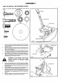
HOW
TO INSTALL
THE STEERING
Attach the steering wheel with the fasteners
below.
WHEEL
shown full size
Bearing
g Post
Control Panel
B
C
A
Upper Steering
Shaft
,,
1.
2.
3.
4.
Look at the hole in the upper steering shaft. Turn the front
tires to the left until the hole in the upper steering shaft points
toward the front.
Slide the steering post through the control panel and on the
upper steering shaft as shown. Fasten with the fasteners as
shown in the illustration.
Turn the front wheels until a 1/2" wrench will fit on the locknut. Make sure the head of the bolt fits around the steering
post. Tighten the Iocknut to a torque of 18 foot pounds.
Slide the bearing on the steering post. Align the holes in the
bearing with the holes in the top of the control panel Fasten
the bearing with the screws as shown.
IIIH
Control Panel
D-4584-t
bearing is correctly installed, if the bearing
becomes loose
or operation,
is damaged,
replace
WARNING:
For safe
make sure
the
immediately.
5.
6.
7.
8.
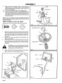
Attach the steering panel to the control panel as follows.
Attach the front tab into the control panel. Move the steering
panel back.Put the two tabsof the steering panel in the control
panel as shown.
To assemble the cover, put the tab in the control panel. Fasten
the top of the cover with the two screws as shown.
Slide the bellows over the steering post. Make sure the collar
ofthe bellows ison top. Push on the top of the bellows. Fasten
the adapter to the steering post with the fasteners as
shown.
Fasten the adapter to the steering post with the bolt and nut
as shown. Tighten to a torque of 18 foot pounds.
Steering Panel
•
ASSEMBLY
9,
Make sure the front wheels point to the front. Attach the
steering wheel to the adapter. Fasten the steering wheel
with the large Washer, the lockwasher washer, and the bolt
shown in the illustration.
Attach the steering wheel cap to the steering wheel.
Connect the ends of the wires for the headlight. Before the
bezel can be assembled, the two screws at the front of the
control panel must be removed. Put the bezel in position on
the end of the control panel. Fasten the bezel with the screws
that were removed,
10.
1 1.
Adapter
Post
D
NOTE: if you do not follow the above assembly instructions
correctly, the steering system will feel loose and the unit will
not steer correctly.
HOW
TO INSTALL
THE TILT SEAT
Assemble the seat with the fasteners shown full size below.
D-4583
SteeringWheel Cap=.....__
I.
2.
3,
Align the four long holes in the seat support to the four holes
in the seat. Make sure the wire from the seat switch sensor
goes through the large hole in the seat support, Fasten the
seat to the seat support with the fasteners as shown, Do
not tighten.
Move the seat to the best position for operating the unit.
Tighten the hex bolts.
Connect the wire from the seat switch sensor to the wire
harness. Make sure the tab part of the connector, from the
seat switch sensor, locks into the latch of the wire harness
connector,
Steering _'¢heel
WARNING: For correct and safe operation of the
unit, you must connect the wire from the seat
switch sensor to the wire harness.
4.
Some
models
have two seat spring
Mount
the caps on the seat springs
D-4591-1
caps in the parts bag,
as shown.
Bezel
Wire from
Sensor"
c
Control Panel
Seat Spring
Cape
Strap
D-4677
9
F-88516
ASSEMBLY
CHECK THE TIRES
Check the air pressure in the tires. Tires with too much air pressure
wilt cause the unit to ride rough, Also, the wrong air pressure will
keep the mower housing from cutting level. The correct air
pressure is shown on the side of the tires. If the air pressure _ not
shown, inflate the tires from 10 to 12 PS1 (0,7 to 0.85 kg!_m2).
HOW TO CHECK THE MOWER
HOUSING
Make sure the level of cut set at the factory is still correct. After you
mow a short distance, look at the area that was cut, If the mower
housing does not cut level, see the instructions on "How To Level
The Mower Housing" in the maintenance section of this instruction
book.
HOW TO ATTACH
0-4606-2
THE HUB CAPS
Plastic
Sleeve
Push each hub cap onto the center hub of each wheel. Make sure
the washer holds the hub cap in place.
FINAL ASSEMBLY
1.
2.
'3.
Battery
The engine is filled with oil. Check the oil. See"HowTo Check
The Ot(" in the Maintenance sectton.
Make sure alI the fasteners are tight.
Read and follow the instructions in the Operation section.
Know the location and purpose of all the controls.
HOW TO INSTALL
/
Battery Tray
THE BA'r-rERY
Use the fasteners shown below to install the battery. The fasteners
are shown full size.
A
C
0-4653-3
1.
2.
3.
4.
Check the level of the acid. If the acid has fallen below the
correct level, add water to the correct level.
Install the battery and the battery tray as shown in the illustration. Make sure the positive (+) terminal is toward the
front of the unit.
Slide the plastic sleeve over the end of the battery clamp.
Fasten the battery withthe battery clamp as shown.
Slide the cover for the positive term inaI on to the red battery
cable as shown.
A
5.
6.
7o
8.
Cover
C
WARNING: To prevent sparks, {asten the red •
cable to the positive (+) terminal before you
connect the black cable to the negative (-)
terminal.
Fasten the red battery cable to the positive (+) terminal with
the nut and bolt as shown in the illustration.
Slide the cover on to the positive (+) terminal.
Fasten the black battery cable to the negative (-) terminal
with the nut and bolt as shown in the illustration.
To prevent corrosion, apply grease to the battery terminals.
RED
10
F-885 t 6
BLACK
OPERATION
Clutch/Brake
Pedal
_4757
KNOW
THE PRODUCT
HOW TO USE THE CLUTCH/BRAKE
Before you operate the unit, read this instruction book. If you
understand the unit and how the unit operates, youwill get the best
performance, When you read this instruction book, compare the
illustrations to the unit. Learn the location of the controls, To help
prevent an accident, follow the operating instructions and the
safety rules. Keep this instruction book for future reference.
THE BLADE
ENGAGEMENT
This unit has only one pedal that is located on the left side of the
unit, The pedal has two functions. The first function is a clutch. The
second function is a brake. Push the pedal completely forward to
stop the unit,
HOW
2,
3.
4.
CONTROL
HOW TO SET THE PARKING
1.
Before you start the engine, make sure the control lever is in
the DISENGAGE position.
Move the control lever to the ENGAGE position to rotate
the blade,
Move the control tever to the DISENGAGE position to step
the rotary blade. Before you leave the operator's position,
make sure the blade has stopped rotating.
Before you ride the unit on a sidewalk or a road, move the
control fever to the DISENGAGE position.
2.
BRAKE
Push the clutch/brake pedal completely forward. Hold the
clutclVbrakepedal in the down position.To engage the parking
brake, raise the parking brake lever and then release the
clutch/brake pedal.
To release the parking brake, depress the clutch/brake pedal.
The parking brake .will automatically disengage.
WARNING:
Before you leave the operator's
position, move the shift lever to the neutral (N)
position. Set the parking brake. Move the blade
engagement
control to the
DISENGAGE
position. Stop the engine and remove the
ignition key.
HOW TO USE THE THROTTLE CONTROL
WARNING: Always keep your hands and feet
away from the blade, deflector opening, and the
mower housing when the engine runs.
Use the throttle control to increase or decrease the speed of the
engine. To start a cold engine, move the tever to the left and into the
START or CHOKE position. For normal operations, move the fever
to the FAST position, The engine governor is set at the factory for
maximum performance. Do not adjust the governor to increase the
speed of the engine.
11
F-88516
TO USE THE LIFT LEVER
The lift lever is on the right side of the unit, To change the height of
cut, raise or lower the lift lever, When you ride on a sidewalk or a
road, move the lift fever to the HI position.
See the location of the btade engagement control in the illustration. Use the blade engagement control to start and stop the
rotary blade.
1.
PEDAL
OPERATION
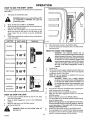
HOW
TO USE THE SHIFT
LEVER
To change the forward speed or the direction of the unit, follow the
steps below:
t.
Fully apply the clutch/brake pedal.
out
of NEUTRAL
REVERSE,
the
WARNING:
Beforeor
you
move the fully
shift apply
lever ir_or
clutch/brake pedal.
2,
3.
4_
5.
Move the shift lever to FIRST or to REVERSE.
Slowly release the clutch!brake pedal, Do not ride with your
foot on the c[utchibrake pedal,
While the unit moves forward, you can select any forward
speed, Just move the shift lever to the next faster or next
slower speed. You do not have to use the clutch/brake
pedal.
The shift lever positionsfor operation of your unit are shown
in the chart below.
Lever
THROTTLE
FUNC ION
j S.IFT
LEVER
Trimming
Shift
5.
6.
1
Move the throttle control to the SLOW position.
To stop the engine, turn the ignition key to the OFF position.
Remove the key.
HOW
o0 ,oo lor2
TO START
THE ENGINE
WARNING:
The electrical system has an
operator presence system that includes a sensor
switch mounted in the seat, These components
==z
m
m
m
Normal mowing
3or4
on the seat, For your protection, always make
tell the electrical system ifthe operator is sitting
sure this system operates correctly, This system
will stop the engine when the operator leaves
the seat if the blade engagement control is
engaged,
m
FAST
Light mowing
5or6
Transpo_
7or8
1.
Check the oil.
2.
Fill the fuel tank with regular unleaded gasoline. Make sure
the gasoline is clean. Leaded gasoline will increase deposits
and shorten the life of the valves.
NOTE: Do not use gasbhol or methanol. Do not use
premium unleaded gasoline.
WARNING:
Always use a safety gasoline
container, Do not smoke when adding gasoline
not
addfuel
gasoline.
Beforeinside
you add
to the
tank, When
an gasoline,
enclosure,stop
do
the engine and let the engine coot for several
minutes,
m
Pull Behind
Attachments
3or4
3.
SLOW-FAST
HOW
1.
2.
3.
4,
4,
5.
TO STOP THE UNIT
Push the pedal completely forward to stop the unit, Keep
your foot on the pedal.
Move the blade engagement control to the DISENGAGE
position.
Move the shift lever to the NEUTRAL position.
Set the perking brake.
6.
7,
WARNING: Make sure the parking brake will
hold the unit.
8,
9.
12
F-88516
Sit in the seat. Push the clutch/_orake pedal completely forward. Keep your foot on the pedal.
Move the shift lever to the neutral (N) position.
Make sure the blade engagement control is in the DISENGAGE position.
Move the throttle control to the CHOKE position.
Turn the ignition key to the START position. Release the key
when the engine starts.
NOTE: If the engine does not start after four or five tries,
move the throttle control to the FAST position. Again try
to start the engine, if the engine w!!! not start, see the
TROUBLE SHOOTING CHART,
Slowly move the throttle control to the SLOW position,
Let a cold engine run for several minutes. Begin work when
the engine is warm. To start a hot engine, move the throttle
control to a position between FAST and SLOW.
OPERATION
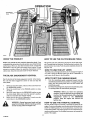
HOW TO OPERATE WITH
THE MOWER HOUSING
HOW
3.
4,
5.
6.
7,
8.
THE UNIT ON HILLS
WARNING; Do not ride up or down slopes that
are too steep to back straight up. Never ride the
unit across a slope, See the "Slope Guide" inthe
back of this book for information on how to
check slopes.
, WARNING: The deflector is a safety device. Do
not remove the deflector. The deflector forces
the discharged material toward the ground.
Always keep the deflector in the down position.
If the deflector is damaged, replace it with a
factory replacement part.
1.
2.
TO OPERATE
1.
2.
Start the engine.
Move the lift lever to a height of cut position, in high or thick
grass, cut the grass in the high position first and then lower
the lift lever to a lower position,
Move the throttle control to the SLOW position.
Move the blade engagement control to the ENGAGE position.
Push the clutch/brake pedal completely forward.
Move the shift lever to the first speed setting.
IMPORTANT: When you mow in heavy grass or mow
with a bagger, put the shift lever in the slowest speed.
Slowly release the clutch/brake pedal.
Move the throttle control to the FAST position, if you need to
go faster or slower, move the shift lever to another speed
setting.
3.
4.
5.
Before you ride up or down a hill, move the shift lever to the
slowest speed,
Do not stop or change speed settings on a hill. If you must
stop, quickly push the clutch/brake pedal forward and set the
parking brake.
To start again, make sure the shift fever isthe slowest speed.
Move the throttle control to the SLOW position. Slowly
release the pedal,
if you must stop or start on a hilt, always have enough space
for the unit to roll when you release the brake and engage
the clutch.
Bevery careful when you change directions on a hill. To help
prevent an accident, move the throttle control to the slow
position on a slope and in a turn,
WARNING: For better control of the unit, always
select a safe speed,
MAINTENANCE
i
lilt, i,i .....
Use the following maintenance section to keep your unit in good
operating condition,
WARNING: Before you make an inspection,
adjustment (except carburetor), or repair, disconnect the wire from the spark plug.
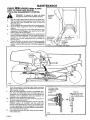
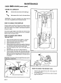
HOW
TO REMOVE
Slide Backto Remove
THE SIDE PANEL
To help service and clean the engine or the transmission, the rear
side panels can be easily removed.
t,
2.
Remove the large screws that hold the' front of the side
panel.
Slide the side panel back app,__.ximately one inch, Remove
the side panel,
0
O-461 t-_
13
F-885t6
MAINTENANCE
FIRST 2
HOW
HOURS (after 2 mowings)
TO CHANGE
THE OIL
NOTE: Drain the oil when the engine is warm.
Be careful,
get oil on the belts,
1.
4.
do not
ap
Put the plastic drain tube into the otI drain valve, Put the
other end of the drain tube into a container as shown. Turn
the oil drain valve counterclockwise
5.
to open the valve. Drain
the oil completely from the engine. Turn the oil drain valve
clockwise to close the valve. Remove the plastic drain tube.
2.
UseaSD,
SE,orSFdetergentgradeoi!.Detergentollhelpsto
clean the engine.
3,
EVERY 5
Nothing must be added to the oil.
Before you change the oil, use the temperature
to select the viscosity grade of the oit to use.
chart below
IMPORTANT:
engine runs.
1.
2.
3,
0°
32 ° 40 °
60 °
80 °
100 °
CAUTION: To protect the starting system, use SAE 5W30
when the temperature is below 32 °F.
oil
Dipstick
Plastic Tube
Container
\.,
OIL
F-88S_6
HOURS (every 5 mowings)
HOW TO CHECK THE OIL
Temperature range before the next oil change. All oils must be
A,P,I. service grade SD, SE, or SF,
Recommended SAE viscosity grades
-20 °
Clean the area around the dipstick. Remove the dipstick,
Slowly pour approximately 3 pints (1,4 liters) of oil into the
oil extension tube.
insert the dipstick into the oil extension tube, Turn the
dipstick in a clockwise direction until it is tight. Remove the
dipstick, Check the oil level on the dipstick. The oil level must
reach the FULL mark on the dipstick.
14
4.
Do not check the level of the oil when the
Stop the engine. Wait several minutes to let the oil drain,
Make sure the unit is level,
Clean the area around the dipstick. Remove the dipstick,
Wipe the oil from the dipstick,
Insert the dipstickinto the oil fill tube, Turn the dipstick clockwise until it is tight. Remove the dipstick. Check the oil level
on the dipstick. The oil level must reach the FULL mark on
the dipstick.
tf necessary, add oil until the oil reaches the FULL mark on
the dipstick. Do not add too much oil
MAINTENANCE
EVERY 25
i i,i i1_
HOURS (twice a year)
i i¸
i,,
. ....
HOW TO CHECK AND ADJUST
THE BLADE ENGAGEMENT
CONTROL
WARNING: To
prevent
injury,correctly.
the blade
engagement
control
mustan
operate
1.
2.
Position
Stop the engine. Disconnect the wire from the spark plug.
Before you adjust the blade engagement control lever, check
and level the mower housing, See "How To Level The
Mower Housing".
Set the height of the mower housing in the lowest position.
Move the blade engagement control to the DISENGAGE
position.
Check the blade engagement control lever. Before the blade
engagement control engages, there must be I/8" to 3/8"
(3mm to 9ram) of free movement.
If an adjustment is needed, disconnect the clevis from the
pivot rod and bracket assembly. Turn the clevis clockwise to
decrease the free movement of the blade engagement
control. Turn the clevis counterclockwise to increase the
free movement.
Connect the clevis to the pivot rod and bracket assembly.
Move the blade engagement control to the DISENGAGE
position. Check the free movement of the blade engagement
control,
3,
4.
5,
6,
7,
Pivot Rod
And Bracket
Assembly
' +;_.
L%.
- Oom.,o.o,y
To
Disengaged
Position
D4s_o
_1/8" (3ram) - 3/8" (9,re,m)
.....
Clevis
Clockwise
O
O
D-4755
8,
9.
10.
11,
12.
Check the operation of the blade brake. Rotate the pulley
with your hand. Make sure that the blade brake pad presses
tightly against the pulley.
Move the blade engagement control to the ENGAGE position, Check the blade brake pad. If the blade brake pad is
excessively worn or damaged, replace the blade brake pad
assembly. Correct replacement parts and assistance are
available from an authorized service center,
Mow for a short distance and again check the operation of
the blade engagement control.
When you move the blade engagement control to the DISENGAGE position, all movement will stop within five
seconds if the adjustment is correct. If all movement does
not stop, again adjust the blade engagement control beginning with the first step, If you need assistance, take the unit
to an authorized service center.
Ifyou replace the mower drive belt, adjust the blade engagement control lever,
PadAgainstPulley
With BladeControl
in DfSENGAGE
Brake Pad
Away From Pulley
With Blade Control
! i i In ENGAGEposition
I
I
I
ill
I
i
II
HI
il
II
D-5298
........
F_88516
15
:==::___
j
MAINTENANCE
SVERV2S
BLADE SERVICE
HOURS (twice a year)
_p
connect the wire to the spark plug. if the blade
hits
an object,
stop you
the engine.
the
WARNING:
Before
inspect Disconnect
the blade, diswire to the spark plug. Check the unit for
damage,
Frequently check the blade for excessive wear. cracks, or other
damage, Frequently check the nut that holds the blade. Keep the
nut tight. If the blade hits an object, stop the engine, Disconnect the
wire to the spark plug. See if the blade is bent or damaged. Before
you operate the unit, replace damaged parts with factory replacement parts. Every three years, have an authorized Service person
inspect the blade or replace the old blade with a factory replacement blade,
_[b
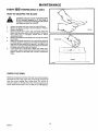
Mandrel
Blade
Hi-Lift Edge Up
Keep a sharp edge on the blade. A blade that is not sharp will cause
the ends of the grass to become brown.
D-4607-t
HOW TO REMOVE AND INSTALL THE BLADE
1.
2.
3.
4.
5.
6.
7,
8.
WARNING: Before you remove the blade, disconnect the wire to the spark plug. The blade
has sharp edges. When you hold the blade, use
gloves or cloth material to protect your hands.
Remove the mower housing. See the instructions on "How
To Remove The Mower Housing".
Use a piece of wood to keep the blade from rotating.
Remove the nut that holds the blade.
Check the blade according to the "Blade Service" instructions. Replace a badly worn or damaged blade with a factory
replacement blade,
Clean the top and bottom of the mower housing. Remove nil
the grass and debris.
Mount the blade so that the hi-lift edges are up as shown, If
the blade is upside down, the blade will not cut correctly and
can cause an accident.
Fasten the blade with the original washers and nut, Make
sure the outside rim of the belleville washer is against the
blade as shown,
Tighten the nut that holds the blade to a torque of 30 foot
pounds (41,5Nm),
WARNING: Always keep the nut tight that holds
the blade, A loose nut or blade can cause an
accident.
F-88516
16
MAINTENANCE
EVERY
HOURS (twice a year)
HOW TO SHARPEN
THE BLADE
WARNING: Vibration can be caused if tile blade
is not correctly balanced or if the blade is
damaged. A blade that is damaged with cracks
can break and cause an accident,
1.
2,
3,
4,
5.
6.
Sharpen the blade two times a year or every 25 hours.
Remove the blade according to the instructions in "HowTo
Remove The Blade",
Clean the blade with a brush, soap, and water. Check the
blade. Look for cracks, nicks, or other damage. If the blade is
bent, badly worn, or damaged, replace with a factory
replacement blade.
Sharpen the blade with afile. Make su re you keep the original
bevel angle.
Make sure the blade is balanced. Use a screwdriver and hold
the blade parallel to the ground as shown. A blade that is
balanced will stay parallel to the ground, If the blade is not
balanced, the heavy end will rotate toward the ground.Sharpen
the heaw end until the blade is balanced,
A new blade will cut batter than a badly worn blade. Every
three years, have an authorized service person inspect the
blade or replace the old blade with a factory replacement
blade.
D-3509-1
Ground
O-4169-1
CHECK THE TIRES
Check the air pressure in the tires, Tires with too much air pressure
will cause the unit to ride rough. Also, the wrong air pressure wil!
keep the mower housing from cutting level. The correct air
• pressure is shown on the side of the tiles. If the air pressure is not
shown, inflate the tires from t0 to 12 PSI (0.7 to 0.85 kg/cm2).
17
F-88516
i
MAINTENANCE
EVERY 50
HOURS (once a year)
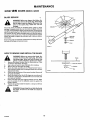
WHERE TO LUBRICATE
_..
_8'_
Lubricate the areas shown with engine _1,
Apply grease with a brush to the areas shown.
IMPORTANT: If the unit is operated in dry areas that have
sand, use a dry graphite spray to lubricate the unit.
HOW
TO CHECK THE MUFFLER
Check the muffler every 50 hours. Make sure the muffler ls correctly
mounted and is not loose. If the muffler is worn or burnt, replace
with a new muffler. A worn muffler is a fire hazard and also can
damage the engine.
oLoJ
If you mount a spark arrestor to the muffler, also check the spark
arrestor every 50 hours. If the spark arrestor is worn or damaged,
replace it with a new spark arrestor.
HOW TO CLEAN AND
•THE BATTERY
1;
2.
3.
4.
5.
6.
7.
8.
CHECK
Remove the black cable from the negative (--) terminal.
Remove the red cable from the positive (+) terminal.
Remove the battery clamp from the battery.
Remove the battery from the unit.
Wash the battery with a solution of one gallon of water and
four tablespoons of baking soda (sodium bicarbonate). Make
sure the solution does not get into the battery cells.
Clean the terminals and the ends of the cables with a
wire brush.
Install the battery. See "How To InstalI The Battery".
Check the level of the battery acid. The battery acid must
touch the bottom of the vent. If the battery acid has fallen
below the correct level, add water to the correct level. Do not
add battery acid to a charged battery or the result can be
an explosion.
I
D-4729-!
IMPORTANT: The battery will be damaged if the battery acid is
not kept at the correct level,
Front
Drive
Chain
Drive Chain
HOW
F-88516
18
TO CHECK THE SPARK
PLUG
1.
Check the gap of the spark plug with a feeler gauge. The
correct gap is 0.030".
2.
For easy starting and good performance, replace the spark
plug every two years.
MAINTENANCE
EVERY 50
HOURS (once a year)
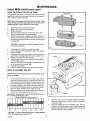
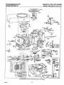
HOW TO CLEAN THE AIR FILTERS
Cover Screws
The engine has two filters, an outer foam filter around an inner
paper fiiter. Clean the alr filters every 50 hours, tf you operate in
dirty conditions, service more often,
NOTE; Never run the engine with the air filters removed. The air
filters will help protect the engine against wear. For the correct
replacement filter, see the parts list for the engine,
1.
2.
3.
4,
5,
6,
Remove the cover screws from the cover.
Remove the cover from the air cleaner.
Remove the filters,
Clean the inside of the base and the cover with a cloth,
Remove the foam filter from the paper filter,
Wash the foam filter in a detergent and water solution. To
remove the water solution, tightly roll the foam fitter in a dry
cloth. Remove the foam filter from the cloth. Completely dry
the foam filter.
CAUTION: Do not wash the filters
solvents that will burn.
Cove r
Filter
Fear
in gasoline or other
8aBe
O-4771
7.
8.
9.
10.
11
12,
13,
Evenly apply S.A,E. 30W oil to the dry foam filter.
To clean the paper filter, lightly tap the paper filter against a
hard flat surface.
If the paper filter is very dirty, replace the filter or wash the
paper filter in a detergent and warm water solution. Use a
detergent that has low suds or no suds.
Wash the paper filterwith water flowing from the inside out
until the water is clear.
Before you assemble, let the paper filter completely dry in the
air. Do not put oil on the paper filter,
Assemble the air filters.
install the cover. Fasten the cover with the cover screws.
|
Dipstick
HOW TO CHANGE THE OIL
Oil Drain
Valve "_
NOTE: Drain the oil when the engine iswarm. Be careful, do not
get oil on the belts.
1.
2.
3.
.,
Put the plastic drain tube into the oil drain valve, Put the
other end of the drain tube into a container as shown, Turn
the oil drain valve counterclockwise to open the valve, Drain
the oil completely from the engine, Turn the oil drain valve
clockwise to close the valve, Remove the plastic drain tube,
Use a SD, SE, or SFdetergent grade oil, Detergent oil helps to
clean the engine. Nothing must be added to the oil.
Before you change the oil, use the temperature chart below
to select the viscosity grade of the oil to use.
Container
Temperature range before the next oil change, All oils must be
A.P.I. service grade SD. SE. or SF.
Recommended SAE viscosity grades
F-4620
4,
!
I
-20 o
0 o
32 ° 40 °
60 °
r
5.
80 °
100 °
CAUTION: To protect the starting system, use SAE 5W30 oil
when the temperature is below 32 °F.
19
F-885t6
Clean the area around the dipstick, Remove the dipstick.
S|owly pour approximately 3 pints (1.4 liters) of oil into the
oil extension tube,
Insert the dipstick into the oil extension tube, Turn the
dipstick in a clockwise direction untit it is tight. Remove the
dipstick. Check the oil level on the dipstick, The oil level must
reach the FULL mark on the dipstick.
REPAIR AND ADJUSTMENT
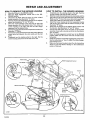
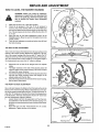
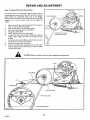
HOW TO REMOVE
1,
2,
3,
4.
5,
6.
7.
8,
THE MOWER
HOW TO INSTALL
HOUSING
Move the rift lever to the MIDDLE position.
Move the blade engagement control lever to the DISENGAGE position,
Disconnect the blade drive tink from the pivot md_nd
bracket assembly, See illustration "C" below,
Remove the hair pins that hold the hangers to the adjuster
plates. See illustrations "A" and "B" below,
Move the mower housing to the left until the right side
hanger separates from the adjuster plate, Then, move the
mower housing to the right until the left side hanger
separates from the adjuster plate.
Remove the long ptnfrom the front suspension bracket. See
illustration "D" below,
Remove the mower drNe belt from the stack pulley. Slide the
mower drive belt between the stack pulley and the belt
guide,
Completely turn the steering wheel to the right, Pult the
mower housing away from the left side of the unit.
1,
2.
3.
4.
5,
6.
7,
8.
THE MOWER
HOUSING
Completely turn the steering wheel to the right, Push the
mower housing under the left side of the unit,
Slide the mower drive belt between the stack pulley and the
belt guide. Put the mower drive belt around the stack puliey,
Make sure the "V" side of the mower drive belt isagainst the
stack pulley. Make sure the drive belt is not twisted.
Attach the mower housing to the front suspension bracket
with the long pin. Fasten with the washer and hair pin. See
illustration "D" below,
Attach the rear hangers to the adjuster plates. Fasten with
the hair pins. See illustrations "A" and "B" below,
• Connect the blade drive link to the pivot rod and bracket
assembly, Fasten with a clevispin and a hair pin. See illustration "C" below.
Move the blade engagement control lever to the ENGAGE
position, Make sure the mower drive belt is inside all the
belt guides.
Check the operation of the blade engagement control lever.
See the instructions on "How To Adjust The Blade Engagement Control Lever."
Make sure the mower housing is level. See the instructions
"How To Level The Mower Houslng" in the maintenance
section of this book,
Stack Pul!
Engagement Control
Beit
Driw
Link
PullPin
Adjuster Plato
D
Hanger B
Height of Cut
Lever
Mower
Drive Bel
Front
Suspension
Bracket
A
/
uster Plate
D.4746-1
F-88516
2O
Pivot Rod and _,_
BracketAssembly
I
"_
C
REPAIR
AND ADJUSTMENT
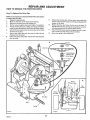
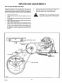
HOW TO REPLACE
THE MOWER DRIVE BELT
1,
2.
3.
4.
5.
6.
7.
8.
9,
Move the lift lever into the low cut position.
Slide the mower drive belt between the stack pulley and the
belt guide. Remove the mower drive belt from the stack
pulley,
Pull the belt guide away from the idler pulley, Remove the
belt from the idler pulley.
While you push the belt guides away from the mandrel
pulley, remove the mower drive belt from the pulley,
install the new mower drive belt,
IMPORTANT: Replace the mower drive belt with a
factory replacement belt.
Make sure the "V" side of the mower drive belt is against the
mandrel pulley. Also make sure the mower drive belt is
not twisted,
Pull the belt guide away from the idler pulley, Put the mower
drive belt around the idler pulley. Make sure the "V" side of
the mower ddve belt is against the pulley. Also make sure the
mower drive belt is not twisted°
Make sure the mower drive belt is inside all the belt guTdes.
WAR NING: If the mower drive belt is outside of
a belt guide when the blade engagement control
can continue to rotate and damage the mower
lever
is in Before
the DISENGAGE
the blade
drive belt.
you operateposition,
the mower,
make
sure the mower drive belt is inside all the belt
guides.
Before you mow, check the blade engagement control lever.
See the instructions on "How To Adjust The Blade Engagement Control Lever".
HOW TO REPLACE
DRIVE BELT
t.
2.
3.
4.
5.
6.
7,
8,,
9,
10.
THE MOTION
Remove the mower housing, See the instructions on "How
To Remove The Mower Housing".
Slide the motion drive belt off the idler putley.
Remove the motion drive belt from the drive pulley.
At the stack pulley, remove the motion drive belt from the
upper pulley.
Remove the motion drive belt from the stack pulley as
foliows. Pull the motion drive belt completely toward the
rear, Slide the motion drive belt between the stack pulley and
the belt guide.
InstaII the new motion drive belt around the top pulley of the
stack pulley.
IMPORTANT: Replace the motion drive belt with a factory
replacement belt,
Make sure the "V" side of the motion drive belt is against the
stack pulley.
Put the motion drive belt around the drive pulley,
Put the motion drive belt around the idler pulley as shown.
Make sure the "V" side of the motion drive belt is against the
idler pulley, Also, make sure the belt is not twisted,
Instafl the mower housing. See the instructions on "How To
Install The Mower Housing",
Idler
Motion
Drive
i
D-4729-1
F-88516
21
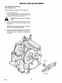
REPAIR
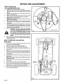
HOW TO LEVEL THE MOWER
AND ADJUSTMENT
HOUSING
"X" Mark
WARNING: Before you make an inspection.
adjustment, or repair to the unit, disconnect the
wire to the spark plug. Remove the spark plug
wire to prevent the engine from starting_by
accident,
I.
Make sure the unit is on a hard level surface.
2.
Check
the air pressure
incorrect,
the mower
in the tires.
housing
will
the tires are inflated to the pressure
tire, If the air pressure
If the air pressure
not cut level
shown
is not shown,
is
Make sure
on the side of the
inflate the tires from
10
to 12 psi.
3,
Move
the
ENGAGE
middle
4,
There
lever for the
blade
engagement
centre]
to the
position. Move the lever for the height of cut to the
position,
are two
adjustment
procedures
below
that
will level
"X" Mark
the blade housing,
Mark
D-4747
r
THE SiDE TO SIDE ADJUSTMENT
Use a ruler and measure
bottom
of the mower
the distance from
housing.
Measure
the ieve] surface
the distances
to the
at the bot-
tom of the mower housing under the two side "X" marks, The "X"
marks are on the top of the mower housing as shown in the illustration, The measurements
must be within _" of the same height,
the measurements
are more than '_", adjust as follows,
1.
2,
3.
4.
tf
LevelSurface
l lll.
Disconnect one or both of the hangers from the adjuster
plates.
The higher numbers on the side of the adjuster plates will
raise the height of the mower housing. The lower numbers
will lower the mower housing.
Connect the hangers into the hole of the adjuster plates that
will level the mower housing, Fasten the hangers to the
adjuster plates with the hair pins.
Check the measurements at each side of the mower housing,
See the above instructions.
HH.."H
/_
:"_
".H
I
Hair
THE FRONT TO BACK ADJUSTMENT
Adjuster Plate
0-4605-2
Use a ruler and measure
the distance
from
the level surface
to the
bottom of the mower housing. Measure the distances at the bottom of the mower housing under the front'X"mark
and the rear"X"
Suspension
mark, The "X" marks are on the top of the mower housing as shown
in the illustration,
The front measurement
must be V,=" lower than
the rear measurement.
Adjust as follows,
1.
Loosen the jam nut from the suspension
Rod
rod, Turn the lock-
nut clockwise to raise the front of the mower housing, Turn
the !ocknut counterclockwise
to lower the front of the mower
2,
housing.
Check the
adjustment,
front
and
Tighten
rear
measurements
for
the
correct
Suspension
the jam nut as shown.
Bracket
Jam Nut
D_4370-2
F-88516
22
Adjusting
ounterciockwise
REPAIR AND ADJUSTMENT
HOW TO SERVICE
THE FRICTION
DRIVE
How To Replace The Drive Disc
NOTE: It is not necessary to disassemble the friction drive system
to replace the drive disc.
1.
Engage the parking brake.
2.
Move the shift lever to the fastest speed position.
3.
Disconnect the spring from the carriage arm.
4.
Set the mower housing in the lowest helght of cut position.
5.
To keep the drive disc from rotating, put a large screwdriver
under the drive disc between the fins and the frame chassis.
6.
Use a 9/t 6 inch socket wrench to remove the nut that holds
the drive disc in place.
7.
Remove the motion drive belt from the belt idler. See the
drawing. Insert (A) below.
8.
Pull on the motion drive pulley until the drive disc separates
from the shaft.
9.
10.
11.
12.
Remove the old drive disc. Lift the motion drive pulley into
position. Align the shim washer and the special (double DID)
washer on the shaft.
Replace the drive disc. Fasten the hex nut to the shaft. To
keep the drive disc from turning, put a screwdriver under the
drive disc between the fins and the frame chassis.
Use a 9/16 inch socket wrench and tighten the nut to a torque of 18 foot pounds. Remove the screwdriver.
Attach the spring to the carriage arm.
B
Locknut
Drive Disc
.___
pecial Washer
(Double DID)
Shim Washer
Shaft
Carriage Arm
\
6
Motion
I
A
|let
0x Nut
'"After the parts are assembled
to 16-18 foot pounds.
_y
Motion
Drive
Drive Disc
Spring for
Belt idler
Spring
D-4664-1_
D-4729-_
23
F-88516
REPAIR AND ADJUSTMENT
How To Replace The Friction Disc
1.
2,
3.
4,
5.
6.
7.
8.
9.
10,
11,
12,
13.
Move the shift lever to a forward speed position.
Disconnect the spring from the carriage arm,
Move the shift lever to the NEUTRAL position.
Use a screwdriver and remove the E-ring from the carnage
rod,
Loosen the setscrew at the carriage arm,
Remove the carriage arm from the hex shaft and the
carriage rod,
Use a 1/2 inch wrench to remove the three screws from the
friction disc.
Remove the friction disc. Use a factory replacement part to
replace the friction disc. Use the three screws to fasten the
new disc in place, Tighten the screws to a torque of 36 to 40
inch pounds.
Slide the carriage arm on to the hex shaft and the carriage
rod.
Fasten the E-ring on the carriage rod.
Tighten the setscrew on the carriage arm to a torque of 8 to
t 0 foot pounds,
Move the shift lever to a forward speed position,
Attach the spring to the carriage arm,
13-4602
Index
Bracket
How To Adjust The Index Bracket
1.
2_
3,
4.
5.
6,
7,
8.
Engage the parking brake.
Move the shift lever to the slowest speed position.
Tilt the seat forward. Check the distance between the neutral
arm and the neutral bracket. The distance must be approximately !/16 inch as shown. If the distance is not correct,
adjust as follows,
Loosen the two nuts on the index bracket,
To find the location for the index bracket, hold a 1/8 inch
shim ore screwdriverbetween the neutral arm andthe neutral
bracket as shown. Move the index bracket sothat the neutral
arm ls tight against the shim, but keep the shift lever in the
slowest speed position.
Tighten the two nuts on the index bracket,
Move the shift lever to the NEUTRAL position. Make sure the
neutral arm sets _nthe notch of the neutral bracket.
Move the shift lever to the slowest speed position, Check the
distance between the neutral arm and the bracket. The distance must be approximately 1/16 to 1/8 inch.
Z
Neutral
Neutral Bracket
D-4626-1
_4602
F-88516
24
REPAIR AND ADJUSTMENT
How To Adjust The Brake
:i
1,
2,
3.
4.
5.
6.
Move the shift lever to any speed setting.
Release the parking brake,
Check the distance between the brake pad and the brake
drum, The distance must be approximately 3/16 to 1/4 inch.
If the distance is not correct, adjust as follows,
Move the mower housing to the lowest height of cut for more
work clearance.
Disconnect the adjustable nut from the brake rod,
To reduce the distance between the brake pad and the brake
drum, turn the adjustable nut clockwise. To increase the distance, turn the adjustable nut counterclockwise,
Clockwise
©©
Brake Rod
3/16 to 1/4"
Washer
Brake Pad
Adjustable Nut
Hair Pin
C-4609-2
Parking Brake
\
Brake Link
Brake Rod
D_4609-2
25
F-885 t 6
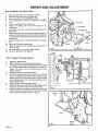
REPAIR AND ADJUSTMENT
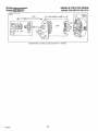
How To Check The Front Drive Chain
Chain idlers
Put the rider mower on a level surface, Stop the engine, Push the
clutch/brake pedal forward, Move the shift lever to any forward
speed. Release the clutch/brake pedal. Look at the distance
between the top and bottom halves of the front drive chain, l_Pthe
distance is V4" or less, the drive chain must be adjusted as
follows.
1.
2.
3.
4.
5.
6.
7.
8,
9,
Front Drive Chain
Make sure the brake is correctly adjusted. See the instructions on "How To Adjust The Brake",
Move the shift lever to the NEUTRAL position.
Disconnect the spring from the chain idlers,
Engage the parking brake.
Loosen the three nuts on the chain bridge.
To adjust the chain, slide the chain bridge back. Hold the
bridge in place. Tighten the three nuts to hold the bridge
in place,
Check the front drive chain: Make sure the chain has no more
than 3/16 inch of movement as shown.
Connect the spring to the chain idlers,
After the front drive chain is adjusted, the rear drive chain
must be adjusted. See the instructions on "How To Adjust
The Rear Drive Chain".
WARNING:
If distance is V4" or less,
adjust the drive chain.
D-4603-t
Before you tighten the front chain,engage
the parking brake,
i
Chain Bridge
Nut
Front Drive Chain
Drive Chain
/
MountingBracket
26
F-88516
REPAIRS AND ADJUSTMENTS
How To Check The Rear Drive Chain
6.
Engage the parking brake, Push the unit forward. This causes the
loose part of the chain to be on top between the two sprockets,The
top part of the rear chain must have 1/4 to 3/8 inch of movement as
shown. If the movement is more than 3/8 inch, adjust as follows,
1.
2.
3.
4.
5.
7,
Check the tension of the chain. Make sure the chain has no
more than 1/4 to 3/8 inch of movement as shown.
Tighten the other two nuts at each axle bracket,
Engage the parking brake.
Loosen the three nuts on each axle bracket at the rear
wheels.
Pull the right axle bracket toward the back ofthe unit until the
chain is tight.
Hold the right axle bracket in prace. Tighten one of the nuts to
hold the axle bracket in place.
Look at the side of the frame above the axle. Find the index
notches. These index notches are a measurement of the
location of the axle brackets. Make sure the position of the
axle bracket on the left side of the unit is like the right side. If
the position is the same, tighten one of the nuts on the
left side.
WARNING:
Do can
not wear
clothing
that isparts,
loose.
Loose clothing
get into
the moving
Notches on Frame
(Top View)
1/4" to 3/8"
Index Notches
Rear DHve Chain
\
Axle Brac
D-4601-2
F-88516
27
REPAIR AND ADJUSTMENT
How To Replace The Bearings
In The Carriage Arms
NOTE: The Bearings are pressed into the carriage arms.
_.
2.
Remove the carriage arms,
Put the carriage arm on a vise or between two blocks of
wood, Allow enough clearance around the surface of the
bearing so that the bearing can be removed,
glasses.
WARNING:
3.
For your protection, use safety eye
Puta punch against the top side of the bearing. Usea hammer
and hit the punch until the bearing releases from the
carriage arm.
CAUTION: Do not use a hammer to put the new bearing
into place. You will damage the bearing.
,
Set the new bearing in the ca rriagearm. Put the carriage arm
and bearing, with a piece of wood against the bearing, into a
vise. Tighten the vise to press the bearing into the
cardage arm.
Bearing
/
Carriage Arm
F-88516
28
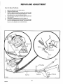
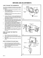
REPAIRS AND ADJUSTMENTS
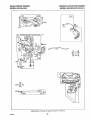
HOW TO/_DJUST
THE CARBURETOR
/dJe Valve
(Located under
the,
)
The carburetor was adjusted at the factory for most conditions.
Differences in fuel, temperature and work load will require a adjustment follows.
1.
Remove the side panel. See the instructions on "How To
Remove AThe Side Panel".
2.
Turn the needle valve clockwise until it just closes. Turn the
idle valve until it just closes,
Idle Speed
Screw
CAUTION: If you turn the valves until they are tight, you
can damage the valves,
3.
Turn the needle valve 1-!/2 turns counterclockwise. Turn
the idle valve 1-1/4 turns counterclockwise. This first adjustment will permit the engine to start and get warm so that a
last adjustment can be done.
Move the throttle control to the FAST position. Turn the
needle valve clockwise until .the engine starts missing (lean
mixture). Then turn the needle valve counterclockwise past
the smooth operating position (rich mixture).
Turn the needle valve to a position between rich and lean so
that the engine can run smooth. (3400 + 100 RPM).
Adjust the RPM. Move the throttle control to the SLOW
position.Turn the idle speed screw until afast idle is obtained
(1750__+ 200 RPM), Turn the idle valve clockwise (lean) and
counterclockwise (rich) until the engine idles smoothly,
Then, turn the idle speed screw so that the engine idles at
1750 + 200 RPM).
Move the throttle controt to the FAST position, If the engine
does not accelerate correctly, adjust the carburetor to a
rich mixture.
4.
5.
6.
7.
HOW TO ADJUST
CONTROL
1,
Move
the throttle
2.
Loosen
3.
Pull the throttle
(F) as shown•
4•
Tighten
screw
screw
Needle Valve
D-524t
Throttle Contrrot
Cable
_
THE THROTTLE
F
D-524t
control to the FAST position•
(C) that holds
cable
FAST POSITRON
the throttle
up until
the
lever
(C). Move the throttle
L
.....
cable in position.
(E) touches
control
to the
link
STOP
position.
HOW
1.
2•
3.
4.
TO REPLACE
THE LIGHT
BULB
\
Remove the two screws from the headlight assembly.
Remove the headlight assembly. Press in the sides of the
light socket. Remove the light socket from the bezel. Turn the
light bulb counterclockwise and remove the bulb.
install a new light bulb.
Fasten the headlight assembly with the two screws as
shown.
/
Console
D-4604
F-88516
29
Screws
Headlight Assembly
Light Socket
REPAIRS
AND ADJUSTMENTS
HOW TO START WITH A WEAK BATTERY
if the battery istoo weak to start the engine, the battery needs to be
charged, If "Jumper Cables" are used to start the engine in an
emergency, follow the procedure below,
NOTE:The unit is equipped with a 12 volt negative to ground system.
Also, the other vehicle must have a !2 volt negative to ground
system.
WARNING: Do not smoke, The fumes from the
battery acid can cause an explosion. Keep the
battery away from anyflames or sparks, To prevent sparks, fasten the red jumper cable to the
positive (+.) terminal before connecting the
black jumper cable.
1,
2.
Put a wet cloth over the vent caps of each battery.
Connect each end of.the_RED"Jumper Cable" to the positive
(+) terminals of each battery. Make sure you do not touch the
chassis with the :cables,
Connect one end of the BLACK "Jumper Cable" to the
negative (-) terminal of the charged batter,/,
Connect the other end of the BLACK "Jumper Cable" to the
engine block,
Start the engine that has the weak battery last. Allow the
engine to run.
To disconnect the "Jumper Cables", reverse the above
steps.
3.
4.
5.
6.
STORAGE
(Over 30 Days)
If the unit is not used for over 30 days, prepare the unit for storage
as follows,
THE BATTERY
1.
THE ENGINE
1.
2.
3.
4,
Completely
charge the battery', See the instructions
To Prepare And Charge
2,
Run the engine until the engine is warm.
Stop the engine.
Change the oil
Clean the air filter,
Clean
the battery
terminals
and the top of the battery
of
any deposits.
3.
Do not remove
the battery
from
the unit.
NOTE: After a long period of time in storage, the battery must
be charged,
THE FUEL SYSTEM
CLEAN THE UNIT
WARNING:
Always use a safety gasoline
container. Do not smoke when adding gasoline
to the engine. When inside an enclosure, do not
fill with gasoline. Before you add gasoline, stop
the engine.
Let the engine cool for several
minutes,
1,
2.
3.
Clean the dirt and grass from the engine.
Clean the mower housing.
Use wax to protect the paint,
LUBRICATE
A gasoline stabilizer (Sta-Bil) must be added to the gasoline when
the unit is put in storage. A gasoline stabilizer will prevent deposits
from stopping up the carburetor.
THE UNIT
See the "Lubrication"
30
F-88516
on "How
The Battery",
instructions in this book,
TROUBLE
SHOOTING
(Recoil-Start
Problem
Cause/Repair
The engine will not start.
I,
2,
3.
4,
5.
6.
7,
,
And
Eiectric
CHART
Models)
Turn the ignition key to the ON position.
Fill the fuel tank with clean gasoline,
Connect the wire to the spark plug,
Make sure the CHOKE is activated.
Move blade engagement control to the
DISENGAGE position.
Push the pedal forward. Mo_'e the shift
lever to the NEUTRAL position,
Remove and dry the spark plug, Move
the throttle to the OFF or SLOW position. Turn the fgnitlon key several times
tothe
START position, Install the
spark plug.
Replace the fuse,
9. Replace the spark plug,
10. Tighten the limit switch. Check for a
loose wire, See the wldng diagram.
11. Adjust the carburetor,
12. Drain the fuel tank. Clean the fuel line,
Replace the fuel filter.
13. Check the wiring harnessfor damage or
loose connections.Repairdamaged wire,
14. Add water and charge the battery,
15_ Clean the batter,/terminals or tighten
the battery cable.
16. On electric-starts, replace the solenoid,
17. On recoil-starts, replace the module.
2,
The engine stops when the
blades are engaged,
1.
Check the wiring harnessfor damage or
loose connections. Repairdamaged wire.
The engine is'difficult to start
and the performance is bad.
t.
Connect and "tighten the wire to the
spark plug.
Clean the air filter.
C_ean the air screen.
Drain the fuel tank, Replace the fuel
filter. Fill with clean gasoline.
2.
3.
4.
6.
7.
.
Connect the wire to the sensor in the
seat.
Add oil.
Adjust the carburetor.
Move the throttle control to FAST. Try to
start the engine to clear out excess
fuel,
Replace the spark plug.
Clean the air filter,
The engine does not run
smooth at fast speed.
1,
2.
Replace the spark plug.
Adjust the throttle control.
On slopes, the engine stops.
1.
Mow up and down slopes. Never mow
across a slope.
2.
To activate the seat sensor, always sit in
the middle of the seat.
The engine will not idle,
1.
2.
3.
Replace the spark plug,
Clean the air filter.
Adjust the carburetor.
4.
5.
Adjust the throttle control
Drain the fuel tank. Clean the fuel line.
Replace the fuel filter.
Clean air screen.
Add oil.
3.
Adjust the carburetor.
4.
5,
Adjust the carburetor.
Check for a damaged belt or damaged
pulley,
Stop the engine. Clean the mower
housing.
Replace or sharpen the blade.
3.
4.
Move the shift lever to a slower speed.
Move the throttle control to the FAST
position.
Replace
4.
5.
6.
7.
Clean the mower housing,
Adjust the level of the mower housing.
Adjust the blade engagement control,
Replace the blade idler spring.
2,
Replace the motion drive belt,
A hot engine causes a reduction
of power,
Excessive vibration.
1,
I. "2.
;1, Replace the blade.
2, Tighten the engine bolts.
3, Decrease the air pressure in the tires.
Correct air pressure on side of tire.
The grass does not
discharge correctly.
,
2.
The height of cut is not level
or the performance is bad,
t.
2.
Correct
The unit wil! not move when
the clutch
or sharpen
the blade.
Check the air pressure in the tires.
air pressure
on sidle of tire,
3.
Raise the height
1,
Adjust the clutch.
t.
Replace the motion drive belt.
of cut,
is engaged,
The unit moves slow or stops
when the clutch is engaged,
31
1=-88516
• 3.
MODEL
NO.
502.254152
ELECTRICAL
SCHEMATIC
Battery
Red
I
i!
.
+
e#
12V
Red
l enoid
So
2 Turns Clockwise(""}
FromTheSolenoid
Amm e t e r
I ....o
I
....
t
I
Fuse
I
I
....
50
Starter
I
f
,
BIdck
/._d
Seat
Amp
Swi
fch
seal unoccupied)
Red
_
AIIoc_en!
Tronmlssion
Interlock
_Itch Inferlock
Svifch
Swi fch
I Igniil°n
Ldlsengaged]
1'--+
-I
Lnoutral
|
,Block
Black
Black
O
S(_
Yellow
I
(
I
Yel low
__:)_
Yel low
.N.C.Conne_ior
(closedif unplugged
frm Seat_I fchj
Yellow
Spark Plug
@
o_Solid IgnitionSfafe_
l
Light
Switch
Headt
Red
Red
Inductive type, wire coiled
as seenfromback of control
panel. Lights will not register
on a_eter,
Igni
I i or_
P0sifton
•F-88516
5wi
°-K}_XX,\
M-G
On
fl-L
Stert
B-S
-o_
3 Amps,
at Max.
20 Vac(Min.)
RPM
f
Clrcui!
Off
2. ;2 Amp
Charging
Coil
Recf
i f i er
(Diode)
Red
ighf
Chassis
Ground
32
MODEL
NO.
502.254152
REPLACEMENT
PARTS
PICTORIAL WIRING
DIAGRAM
24
/21
19
18
27
FUSE
12
26
STARTER
28
D-4637-5
KEY
PART
NO, DESCRIPTION
.
NO,
1 Cable, Battery
24x24
2 Solenoid
24285
3 Screw
26x233
4 Nut, Locknut ¼"-20
STD541425
5 Battery Type: UI-7R
56033
-- Electrolyte (Batter,/Acid) " 90665
6 Bolt, Hex V4"-20x%"
STD522506
7 Cover, Battery Terminal
54148
8 Cable, Ground Battery
24x3
9 Ammeter
90729
10 Limit Switch
24273
11 Fuse, 15 AMP
54212
12 Tray, Batter/
55792
13 Limit Switch
91032
*
MFG.
NO.
KEY
NO, DESCRIPTION
14 Wiring Harness
15 Switch, Ignition
16 Key Only
17 Light Switch
18 Light Socket
19 Light Bulb
20 Solenoid Cap
21 Washer, Shakeproof
22 Nut, Hex
23 Switch, Seat Sensor
24 Cap, Switch
26 Tie, Wire
27 Clamp, Wire
28 Cover, Seat Switch
29 Screw
-- Owner's Manual _
15x66
lx38
Part is not shown.
F-88516
33
PART
NO,
250x5
21064
91275
90647
90155
90084
90565
19x40
91489
9t031SE
91488
32618
21980
56062
STD610803
F-88516
MFG.
NO.
26x 159
MODEL
NO.
502.254152
REPLACEMENT
PARTS
BODY AND CHASSIS
1_4648-4
16
1
1
71
8O
8!
82
33
3O
28
39
43
@
52
15
58
8
63
51
6
64
65
1
55
6
13
59
F-88516
34
MODEL
NO.
502.254152
KEY
NO. DESCRIPTION
1
2
3
4
5
6
7
8
9
10
11
12
13
14
15
16
17
18
19
20
2t
22
23
24
25
26
27
28
29
30
31
32
33
35
36
37
38
39
40
41
Seat
Seat Mount
"Washer
Lockwasher
Bolt, Hex 5/t6"-20x%
'_
Locknut %"-16
Spring, Seat
Screw
Retainer, Seat Spring
Hanger, Seat Spring
Support, Seat
Bolt, Hex ¼"-20x%"
Locknut 5/16"-18
Strut, Index Bracket
Bolt, Shoulder
Panel, Control
Screw ¼" Type AB xV2"
Cover, Upper Console
Screw
Console, Upper
Screw
Bushing
Bearing, Steering Post
Console
Screw
Reflector
Lens
Bezel
Screw
Bulkhead
Throttle Control
Locknut ¼"-20
Bracket, Index
Receiver
Retainer, Stud
Panel, Access
Stud
Body, Rear
Plate, Index
Receptacle
+ See replacement
F-885t 6
REPLACEMENT
PARTS
BODY AND CHASSIS
PART
NO.
91451
55359E601
STD551031
18x16
STD523106
STD541437
164x17
26x49
90014
55062
55366
STD522506
15x76
55617E601
9x29
55823E701
26x238
55414
26x161
55413
STD610803
55717
56022
70231SE
26x201
55351C
55428
55422
26x214
55349E701
55424
STD541425
5543OE6Ot
55487
55485
56067E601
55486
70240
55365
28x52
parts page 47 for component
MFG.
NO.
KEY
NO. DESCRIPTION
PART
NO,
42 Screw
91330
43 J-Nut V4"-20
28x18
44 Locknut5/16"-18
STD541431
45 Grommet
21268
46 Bracket,
55358E601
47 Panel, Front
55392E601
48 U-Nut ¼"-20
28x20
49 Support, Console
55350E701
50 Clamp, Battery
55253Z
5t Support, Body
55360
52 Mat, Left
55103
53 Mat, Right
55102
54 Cover, Battery Clamp
55804
55 Frame Channel
55946
56 Screw
26x213
57 Screw, Hex Head
6x74
58 Washer, Shakeproof
STD551231
59 Bolt, Engine Mount
25x6
60 'v_asher, Shakeproof
t9x8
61 Bolt, Hex 5/16"-18x3%
'r
lx118
62 Muffler
56029
63 Engine, Briggs & Stratton
Model 5oo.2537o7-o213-ot + 55811PA
64 Fitting, Oil Drain
55704
65 Hose, Oil Drain
55705
68 Screw, HX #10-24x,&"
4x2OZ
69 Nut #10-24
15x81Z
70 Screw ¼"-AB x%"
26x239
71 Bolt, Shoulder
9x30
72 Cap, Fuel Tank
55988
73 Tank, Fuel
55805
74 Bracket, Fuel Tank
55806E701
75 Filter, Fuel +
......
76 Clamp, Hose
23713
77 Hose, Fuel Line
91022
78 Cover, Seat Spring
20107
79 Hose Clamp
91174
80 Screw
STD611OO5
8! Rod, Hinge
56066Z
82 Pin, Cotter
STD560907
17x47Z
Ix45
15x84
lx38
26x159
15x82
parts.
35
MFG.
NO,
15x88
19x6
26x235
3Ox50
MODEL
NO.
502.254152
DRIVE
PARTS
SYSTEM
D_4702-3
3
4
1!
55
42
17
18,,.
26
25
54 /
33
6O
\
/
37
46
36
47
51
49
\
58
F-88516
36
6 "/I
35
MODEL
NO.
502.254152
REPLACEMENT
PARTS
DRIVE SYSTEM
KEY
NO. DESCRIPTION
1 Bolt, Carriage
2 Drive Assembly, Friction _
3 Chain, Roller
4 Link, Master
5 . Sprocket Assembly
6 Pin, Cotter
8 Locknut 5/16"-18
9 Bott, Shoulder
10 Bridge
11 Washer, Shakeproof
12 Washer
13 Pin, Hair
14 Locknut %"-16
15 Pedal
17 Spring, Brake Arm
18 Spring, Drive Idler
19 Locknut 5/16"-18
20 idler Arm Assembly
21 Bolt, Shoulder
22 Key, Square
23 Pulley, Motion Drive
24 Locknut 3/8"-16
25 Pulley, Idler
26 Belt, Motion Drive
27 Pulley, Stack
28 Washer, Shakeproof
29 Bolt, Hex 7/16"-20x1"
30 Guide, Belt
3 t Screw
32 Bearing, Flange
33 Bracket, Rear Axle
34 Differential Peerless Model No. 100-029A +
35 Lever Assembly
_36 Link, Spring Wire
37 Rod, Brake
38 Nut, Adjuster
39 Chain, Roller
40 Link, Master
41 Sprocket and Guard Assembly
42 Nut, Hex 5/16"-18
43 Washer
44 Valve Stem and Cap
45 Tire Only
46 Wheel Only
47 Key, Square
49 Retainer Ring
50 Washer
51 Hub Cap
54 Rod, Parking Brake
55 Grip, Parking Brake
56 Pin, Cotter
57 Link, Parking Brake
58 Washer
59 Stop, Parking Brake
60 Pin, Clevis
See replacement
parts page 44 for component
parts.
+ See replacement
parts page 46 for component
parts.
F-88516
37
PART
NO,
STD533107
55650-701
55839
55556PA
56018
STD560907
STD541431
9x25
55838E601
STD551231
STD551037
STD624003
STD541437
55825
165x58
165x43
STD541431
55512Z
9x30
55634
55100
t5x98
91178
37x51
55961Z
STD551243
lx80
55982Z
26x49
55597
55065E60t
55872
55656
5C890
55664Z
21920
55666
407059
55915
STD541031
17x115Z
24373
90589
91523
STD580105
STD581075
ST0551050
24582
55822Z
55873
STD560907
55821Z
17x36Z
55820
29x95
MFG.
NO.
2x53Z
30x20
15x88
19x6
17x53Z
3tx6
15x84
15x76
19x35
15x79Z
21553
11x3
17x103
30x50
MODEL
NO.
REPLACEMENT PARTS
STEERING SYSTEM
502.254152
0-4608-3
44
43
1
d
10
\
/
8_
25
16
7
1t
%j18
9
2O
!5,
24_,
i
1
32
30
33
27
46
28
34
F-88516
30
38
MODEL
NO.
502.254152
REPLACEMENT
STEERING
KEY
NO.
1
2
3
4
5
6
7
8
9
10
11
12
13
14
15
16
17
18
19
2O
21
22
23
24
25
26
27
28
3O
31
32
33
34
35
36
37
38
39
4O
41
42
43
44
45
46
PART
MFG.
NO.
NO.
55919
55909
STD523115 lx102
STD541431 15x88
91444C
17x132
STD533107 2x64
26x49
55384
STD541031 15x79
56023
STD541537 15x87
55937
STD56,12.20_3Ox49
55D03'
55655,
5502_
56057
55746
55046D
!5x61
21031
STD55t037 17x53Z
STD560907 30x20
STD623725 lx69
55381
b5026D
55380
55598
91527
55386
24373
24583
24582
55168
17x100
55547
STD523707 lx85
DESCRIPTION
Cap, Steering Wheel
Steering Wheel
Hex Bolt 5/16" -18xl ½"
Locknut, Flange 5/16" -13
Steering Post
Washer
Carriage Boit 5/16"-18x3/4 ''
Screw, Tapping
Suspension Plate, Left
Hex Nut, Flange 5/16'_-18
Suspension Plate, Right
Locknut, Flange 3/8,,-24
Front Axle Support Assembly'
.Cotter Pin
Spindle Bearing
Front Axle Hanger Ass_emblys
Front Axle Assembly
Pinion Gear
Sector Assembly
Drag Link
Hex Nut %" -24
Steering Ball Joint
Washer
Cotter Pin
Hex Bolt %" -24x2%"
Left Spindle Assembly
Tie Rod
Right Spindle Assembly
Bearing, Flanged *
Wheel Only
Tire Only
Valve Stem and Cap
Washer
Hub Cap
Bearing
Washer
Bushing,Nylon
Bolt, Hex %'-16x_/4"
Washer, Shakeproof
Washer
Adapter, Steering Wheel
Locknut 5/16"-18
Bolt, Contour 5/16"-18xl '/4"
Bellows, Steering Post
Washer, Formed
The part is also included with Key No. 31.
F-88516
39
19x39
20094Z
55911
STD54143!
6x90
55410
t7x161
15x76
PARTS
SYSTEM
MODEL
NO.
502.254152
MOWER
HOUSING
/
D-4529-5
\
5
8
2
©
43
38
/
\
41
Q
34
3"1
/3
37
3O
t
35
23
24
34
12
A
29
31
40
2
_,_3435
12
Fo88516
40
""_ 27
SUSPENSION
MODEL
NO.
502.254152
MOWER
KEY
NO. DESCRIPTION
1
2
3
4
5
6
7
8
9
10
12
13
14
15
16
17
18
19
20
21
22
23
24
25
26
27
28
29
30
31
32
33
34
35
36
37
38
39
40
41
42
43
F_88516
HOUSING
PART
NO.
55449
55928Z
STD54t425
STD522510
55440
STD551050
55853
55439
56031
3x149
STD54143t
55365
26x49
9x9Z
21920
STD551037
STD560907
STD541431
17x48
55656
55930D
165x67
55179D
55139
55298
9x17
STD541237
55957
55271Z
9x4Z
24471Z
STD541031
STD624005
55344
-55270
55346
STD533107
24839D
17x122Z
55326
STD523106
STD541425
Grip, Blade Control Lever
Lever, Blade Control
. Locknut, Flange ¼" -20
Bolt, Hex ¼"-20
Cap, Lifter Lever Knob
Washer
Cam, PTO
Grip, Knob
Lever Assembly, Lifter
Screw 5/16"-18xt½"
Locknut, Flange 3/s'"-16
Plate, Index
Screw
Bolt, Shoulder 3/8"-16
Nut, Adjuster
Washer
Pin, Cotter
Nut, Hex Flange 5/16" -18
Washer
Lever Assembly
Rod & Arm Assembly
Spring, Extension
Link, Front Deck
Bracket, Front Suspension
Clevis
Bolt, Shoulder 3/8" -16
Nut, Hex Jam 3/8"_16
Rod Assembly
Link
Bolt, Shoulder
Clevis, Adjuster
Nut, Hex 5/16"-18
Hairpin
Plate, Adjuster
Plate, Mounting
Rod Assembly, Suspension
Bolt, Carriage
Rod, Lifter
Washer
Strut, Frame
Bolt, Hex 5/16"-18x%"
Locknut, Hex ¼"-20
41
SUSPENSION
MFG.
NO.
15x89
lx76
17x67Z
15x84
17x53Z
30x20
15x88
15x73
15x2
31x4
2x64
lx45
15x66
MODEL
NO.
502.254152
MOWER
HOUSING
BOTTOM HALF
8
/
11
12
|
24
33
28
26
18
\
43
17"'q
28
37
\
17
39
41
{._42
D-4745
F-88516
42
MODEL
NO.
502_;2_5_]ii52;i
................
..........
MOWER
HOUSING
BOTTOM HALF
NO. DESCRIPTION
;: 1 Belt, Mower Drive
2 Pulley, Splined
3 Lockwasher
4 Locknut 9/16x18
5 Nut, Hex
6 Pulley, idler
7 Bracket, Upper Idler
8 Spacer
9 Assembly, Blade Idler
10 Locknut, Flange
11 Pin, Clevis
12 Clevis
13 Bolt, Hex
14 Pin,. Hair
15 Guide, Belt
16 Bracket, Lower Idler
17 Bolt, Carriage *"
18 Nut, Flange *
19 Guide, Belt
20 Spacer
21 Bolt, Hex
22 Housing, Mandrel
23 Guide, Belt
24 Bracket, Hanger*
25 Spring, Compression
,26 Nut, Hex*
27 Spring, Torsional
28 Push On Cap.
29 Rod
30 Bracket, Chute Deflector*
32 Spring, Extension
33 Housing, Blade
34 Bracket, Front *
35 Screw
36 Bolt, Hex 5/16"-18x7/8"
37 Deflector, Chute
38 Mandrel
39 Blade
40 'Washer, Belteville
41 Washer, Hardened
42 Nut, Hex 9/16"-18
43 Pin, Pull
44 Washer
45 Pin, Hair
--
Mower Housing, Complete
* These parts are included with key no, 33.
F-885I 6
43
PART
MFG.
NO.
NO.
37x57
55452
18x33
15x101
STD541450 15x41
91178
55921E601
55895
55979
8TD541431 15x88
29x99
24471Z
STD523106 lx45
STD624003 3 lx6
55977
55920E601
STD533!07 2x53Z
S.TD54103 t' 1.'5X79Z
55894
55273Z
STD525015 lx127
55962
55956Z
55974
164xl
STD541431 15x43Z
166x4
28x23
21197Z
55963
t65x68
56065E601
55916
26x216
STD523117 lx75
55971
55445
56060HT
17x155
t7x154
15x100
90828Z
STD551050 17x67Z
STD624005 31x4
403224
MODEL
NO.
502.254152
REPLACEMENT
PARTS
TRANSMISSION
IN
(.O
co
D4600-2
(O
o
cox
O3
_D
CO
\
\
LO
co
c,q
(D
/
IN
I/_
w
IN
F-88616
44
MODEL
KEY
NO. DESCRIPT|(3N!
1
2
3
4
5
Locknut%_f_] 6
Disc,
Washer_ThruSt
_:
Washe(:_i ii_'........
Locknut ¼"-20
6
7
8
9
10
11
12
13
14
15
16
17
18
t9
20
21
22
23
24
25
26
27
28
29
30
31
32
33
34
Yoke, Left
Yoke, Right
Bolt, Hex ¼"-20x1¼"
Lever, Shift
Spring, Extension
Shift Rod Assembly
Bearing, Flanged
Washer
Pin, Cotter
Bearing, Flanged
Ring, Retainer
Locknut %"-16
Rod, Cardage
Washer, Curved Spring
Arm, Actuator
Bolt, Shoulder
Support, Cardage
Pin, Cotter
Washer
Roller
Idler Assembly, Left
Idler Assembly, Right
Ring, Retainer
Sprocket,//35
9 Tooth
Bearing, Flanged
Spdng, Extension
Rod, Brake Stop
Ring, Retainer
Mandrel
* This part includes Key Number
F-88516
REPLACEMENT PARTS
TRANSMISSION
NO, 5a2_2_!5_:=
PART
NO.
15x98
55500
17x 147Z
17x 149
STD541425
55578Z
55588Z
STD522512
55476Z
165x71
557!1Z
55549
17x36Z
30x50
55548
1 lx8
STD541437
55559
20xt
55643
9x30
55562E701
STD560907
STD551037
55570
55514Z
55513Z
11x18
55543
55651
165x27
56021
11x!3
55635
MFG.
NO.
KEY
NO. DESCRIPTION
15x89
lx94
15x84Z
30x20
17x53Z
34,
45
35
36
37
38
39
40
41
42
43
44
45
46
47
48
49
50
51
52
53
54
55
56
57
58
59
60
61
62
63
64
65
Locknut 5/16"-18
Housing, Bearing *
Screw, Set
Carriage Arm
Bail Bearing Assmbly
Ring, Retainer
Hex Shaft Assembly
Brake Arm Assembly
Bearing, Flanged
Bushing, F{anged
Pivot Rod Assembly
Washer, Curved Spring
Washer
Screw
Bracket, Neutral
Linkage, Shifter
Ring, Retainer
Screw
Retainer, Bearing
Ball Bearing Assembly
Washer
Arm, Neutral
Clip, Carrier Arm
Arm, Carrier
Hub, Friction Disc
Disc, Friction
Screw
Spring
Grip, Inner
Switch, Limit
Screw
66
67
Grip, OuterSpacer
PART
NO.
MFG.
NO.
STD541431
55596
22x57
55638
55639
11x17
56020
55889
55547
55546
55569Z
20x2
STD551037
26x49
55607Z
55526Z
11x12
26x174
55509Z
55541
STD551031
55606Z
55658Z
55608Z
55501
55550
26x207
165x46
20476
24273
26x233
55449
115x2Z
15x88
17x53Z
17x47Z
MODEL
F-88516
NO.
143.100-029A
REPLACEMENT
PARTS
PEERLESS DIFFERENTIAL
KEY
NO. DESCRIPTION
PART
NO.
1
1A
2
3
4
5
6
7
8
10
11
13
14
774345
774344
774532A
774531A
778067
778068
786040
780096
780001
792018
792041
780077
792061
.Housing, Differential carrier (lncl, No. 13)
Housing, Differential carrier (Incl. No. t3)
Axle (8-11/64" long)
Axle (19-3/32" long)
Gear, Bevel
Gear, Pinion
Pin, Drive
Washer, Thrust
Washer
Ring, Snap
Screw, Hex 5/16"-18x3%"
Bushing
Washer
46
BRIGGS & STRATTON ENGINE
MODEL 500.253707-0213-01
it
334
305
356
201
552
BUSH,
232
337 ,_
6,15
635
11
o
230
1
161
757
46
219
"_SPECIAL
TO
525
SEE REPAIR
MA_
Assemblies
F-88516
524
include
all parts shown
47
in frames,
SEARS RIDING MOWER
MODEL 502.254152
l
BRIGGS & STRATrON
ENGINE
MODEL 500.253707-0213-01
643
[887
534A
877
534
28
Assemblies
t:-88516
include
all parts
48
shown
in frames.
BRIGGS & STRATTON
ENGINE
MODEL 500.253707-0213-01
310
Assemblies
F-88516
_
include
_HoU
,NG_LENGTH-_
all parts shown
49
in frames.
BRIGGS & STRA'R'ON
ENGINE
MODEL 500.253707-0213-01
SEARS RIDING MOWER
MODEL 502.254152
KEY
NO,
1
3
5
7
8
9
10
11
12
PART
NO.
395705
391086
212914
*271075
391406
*27803
93394
280100
*270808.
2709 t 5
*270916
!3
93723
t5
16
91084
392299
Note:
t8
20
22
23
391784
291675
93585
391988
24
25
222698
394661
394662
394663
394664
PISTON
26
27
28
RING SETS:
Note:
394665
391781
391782
391783
260924
299691
391286
DESCRIPTION
Cylinder
Assembly
Seal_Oil
Head - Cylinder
Gasket-- Cylinder He_d
Breather Assembly
Gasket-- Valve Cover
ScrewSere
Tube--Breather
Gasket--CrankcaseCover1/64"
thick
Gasket--CrankcaseCover.005"
thick
Gasket--CrankcaseCover,009"
thick
ScrewCylinder Head
(3" .long)
iPlug- Oil Drain
Crankshaft
To replace Crankshaft
Gear Pin
Order'Part
No. 230978
SumpOil
Seal=Oil
Screw-Sump
Mounting
Sere
Flywheel and Ring
Gear Assy. -- Magneto
Key-Flywheel
Piston Assy.-Std.
Piston Assembly.01 O" O.S.
Piston
Assembty°020"
O.S.
Piston Assembly.030"
O.S.
For Chrome Piston Ring
Set- Standard
SizeOrder No. 392331.
Ring Set- PistonStd,
Ring Set-Piston-.010"
Ring Set-Piston-.O20"
Ring Set-Piston--.030"
LockPiston Pin
Pin Assembly-PistonStandard
Pin Assembty-Piston-
,005"
29
391775
Note:
31
32
33
34
35
36
40
41
222299
92909
261185
261462
65906
26828
221 596
292260
F-88516
O.S.
O.S.
O.S.
KEY
PART
NO.
NO,
DESCRIPTION
42
93630
45
46
52
261183
212897
*270872
75
78
94
220865
93805
t292681
Retainer-Exhaust
Valve Rotocoil
(2)
TappetValve
Gear- Cam
Gasket-Carburetor
Mounting
WasherSpring Sealing
Screw-Sere
95
93499
Valve Assembly
Carburetor
Idle
Screw--Throttle
Valve
Choke Valve Mtg, Sere
Screw-Machine
Fill,
98
99
t0t
t04
108
118
121
123
125
126
91920
26157
93043
t230896
222010
t396568
394698
93357
396501
396574
127
128
130
131
t221997
211960
222858
391512
132
133
134
136
137
138
t 41
142
147
211712
299707
t299096
221995
t270511
t222014
390684
t299740
t231323
186
1 87
67218
299146
Connector-Fuel
Line-Fuel (28"
(Cut to Suit)
201
209
216
261609
261306
261610
Link-Governor
Spring-Throttle
Adjustment
Pin-Throttle
Stop
Pin-Float Hinge
Valve--Choke
Valve_Needle
Carburetor
Overhall Kit
Screw-Carburetor
Mtg,
Carburetor
Assembly
Body Assembly
Carburetor
(Two 271 O 13 Foam
Washers
Included in
AIt Ref. 126)
Plug-Welch
Venturi-Carburetor
Valve-Throttle
Shaft and LeverThrottle
Stop-Throttle
Float-Carburetor
Valve-Fuel
Inlet
Bowl-Float
Gasket-Float
Bowl
Washer-Float
Bowl
Shaft and Lever-Choke
Nozzle-Carburetor
Screw-Nozzle
O,S.
Rod Assembly-Connecting
For Connecting
Rod
with .O20"
undersize
Crankpin
Bore-Order
No. 393712.
Lock-Conn.
Rod Screw
Screw-Conn,
Rod
ValveExhaust
ValveIntake
Spring-Intake
Valve
SpringExhaust Valve
Retainer-Intake
Valve
RotocoilExhaust Valve
50
Spring-Gov.
Link-Choke
Pipe
long)
BRIGGS
MODEL
::PART,
:NO:
: . .
:23_O82
1193053
DESCRIPTION
NQ
21£
222
225
396199
231058
391733
230
232
265
284
303
304
305
222450
260584
221535
93804"
91308
391556
93158
306
307
222744
93163
308
309
222725
394805
310
311
319
94003
395538
395326
332
333
334
92264
395492
93381
337
298809
351
352
353
354
355
356
358
363
383
422
423
455
468
482
520
523
91920
66068
92791
90576
66554
299500
393411
19203
89838
222502
93964
222561
222562
93621
93722
391841
524
525
68838
280134
534
534f
535
536
537
544
552
562
93323
93622
270843
391786
270853
392747
231055
92613
Oil Slinger, Gov. Gear
and Bracket Assembly
:_:
Ptate-Gov.
Control
Crank-Governor
(1/4 _; dia):
:i'
Lever Ass, y.-Governor
(For 1i4!_:idiai
Crank) _..
Washei:-iG_Vi_Crank
( 1/4" I.D.)
spri6g_G:_'mor
Link
93306
93307
261116
270382
66538
280118
93496
222311
93572
392134
:Scre'w_iamp
Mtg.
E l:)o:_Muffler
90 o Street
Housing-Blower
Screw-Blower
Housing
Mounting
Sem
Shield-Cylinder
Screw-Cylinder
Shield
Mounting
Sem
Cover-Cylinder,Head
Motor-Starting
(t 2 Volt)
See Chart on Page 5 for
Replacement
Parts for
Starting
Motors.
Thru Bolt Assembly
Brush Assembly
Armature +Assy.
(Less Trigger Coil)
Nut-Hex
395405
93535
261196
212359
391373_
298909
93875
394856
395537
393825
270920
392067
221798
261463
210940
291961
Note:
Armature
Group
Screw-Armature
Mounting
Sem
Plug-Spark
(t-t/2"
high)
877
393814
887
391529
897
394970
& STRATTON
ENGINE
500.253707-0213-01
DESCRIPTION
Nut-Hex
10-24
Clamp-Fuel
Pipe
Cotter-Hair
Pin
Retainer-E-Ring
Spring-Choke
Return
Washer-Choke
Shaft"
Elbow-Spark
Plug
Support-Air
Cleaner Element
Screw-Sem
Bracket-Carburetor
Screw
Gear-Ring
(includes
Mounting
Parts)
Cover-Starter
(Ihcludes Mounting
Screws)
Screw-Sem
Gear-_iming:
:Link-Counterweight
i Counterweight
Assy.
Pin'-COunterweihgt
(1)
Screw-Counterweight
(1)
End Cap Assembly
Drive
End Cap Assembly
Commutator
Housing Assembly
Seat-Oil Filler Cap
Filler Group-Oil
Terminal-Ignition
Cable
Seat-Intake
Valve (StandaYd)
Seat-Exhaust
Valve (Standard)
Guide-Exhaust
Valve
231 218 Guide-Exhaust
Valve
(Brass) See Repair Manual.
Diode and Connector
Assy. (D.C)
Stator AssemblyAlternator
(D.C.)
Trigger
Coil
tlncluded
in Carburetor
Kit-Part No. 394698.
Overhaul
t lncluded
in Carburetor
Kit-Part No, 394698.
Overhaul
*Includes
Brush
Set
_ _lncludes
#391135
Clutch Assembly
(Ref. No, 513
#280104
Gear (Ref. No. 783)
:#391462
Retainer and Pin-(Ref, No. 773)
#93754
Rool Pin (Ref, No, 896)
51
NOTES
F-885"16
52
NOTES i_
F-88516
53
NOTES
F-88516
54
g
0
o
0
0
O
i
°
o
#
_0
0'_
O
0
0
;3
0
O
g
,
"o
o
0
o
,g
0
o
0
g
0
§.
0
0
"0
P
o_
o
a;
0
o
<
0
N
_
3"
E'
:_p
"_
O. _' -._
o_
_
_
r-
toO.
0
m
o
P
o
3
....
m ,NN
m
o
o
c
::g!i:N
i:_:
m>
oN
m
t_
m
F-88S16
55
r
ovvne
The Model Number
is found under the seat on a plate attached
port. Arways give the Model
parts for your unit.
Model No°
502.2541
Number
when
to the seat sup-
you call for service
or order
Repair parts can be ordered from any Sears Service Center/Departments
most Sears Stores.
52
WHEN ORDERING REPAIR PARTS, ALWAYS
INFORMATION AS SHOWN IN THIS LIST.
1.
2.
3.
4.
5.
HAVE THE
repair
and
FOLLOWING
PART NUMBER
PART DESCRIPTION
MODEL NUMBER
NAME OF ITEM
ENGINE MODEL NUMBER
How to Order
Repair Parts
Your Sears merchandise has added value when you consider Sears has service
units nationwide staffed with Sears trained technicians. Sears technicians have
the necessaryParts, tools, and equipment to meet the Sears pledge, "We Service
What We Sell",
F-88516
Sears,
Roebuck
and Co., Chicago,
IL, 80684
U.S.A.
'