1
f
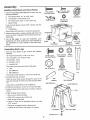
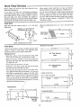
Save This Manual
For Future Reference
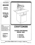
SEARS
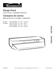
owner's
manual
Model No.
113.299210
Saw with Legs
Two Table Extensions
Motor
Rip Fence and
Miter Gauge
Serial
Number.
Model
and
sedal
numbers
may be found on the left rear
side of the base,
You should record both model
and serial number in a safe
place for future use,
®
10 iNCH
DIRECT DRIVE
TABLE SAW
FOR YOUR
- assembly
. operating
o repair parts
READ ALL
INSTRUCTIONS
CAREFULLY
J
Sears,
Part No, SP5909
Roebuck
and Co., Hoffman
Estates,
IL. 60179 U_S,A.
Printed in US A
FULL ONE YEAR WARRANTY
ON L,RAFTSNIAN
STATIONARY
TOOL
If this stationary tool fails due to a defect in material or workmanship within one year from the date
of purchase, CONTACT THE NEAREST SEARS SERVICE CENTER IN THE UNITED STATES and
Sears wilt repair it free of charge.
This warranty applies only while this product is in the United States.
If this Table Saw is used for commercial
from the date of purchase.
This warranty
state to state.
gives you specific
or rental purposes, this warranty
legal rights,
and you may also have other rights which vary from
Sears, Roebuck and Co°, D/817 WA Hoffman Estates,
Safety Instructions
will apply for ninety days
IL 60179
. .._
For Table Saw
Safety is a combination of common sense, staying alert and knowing how your table saw works,, Read this manual to
understand this table saw
Safety
Signal
Words
DANGER: means if the safety information is not followed
someone will be seriously injured or killed
Before
Using
WARNING:
WARNING: means if the safety information is not foUowed
someone could be seriously injured or killed,
CAUTION: means if the safety information is not followed
someone may be injured,
The Saw
to avoid
mistakes
that
could
cause
blade tilt controls (See "Getting to Know Your Table
Saw" section),
serious, permanent injury, do not plug the table
saw in until the following
steps have been satisfactorily completed.
. Review and understand all safety
operating procedures in this manual.
* Completely assemble and align saw (See "Assembly"
section)
° Learn the use and function of the ON-OFF switch
blade guard, spreader, anti-kickback device, miter
gauge, rip fence, table insert, blade elevation and
instructions
and
, Review the maintenance methods for this saw (See
"Maintaining Your Table Saw" section)),
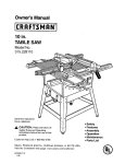
- Find and read all the warning labels found on the saw
(shown below),
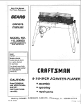
m
®
E23417
12o VoIts
3450 RP M
1 t 5 Amp._
60 Hz_ I Ph
I0" Blade
, WARNING
1,
2.
' 3.
4.
5.
6.
7.
Read manual before usingsaw.
8,, Know how to reduce the risk of kickback,
Wear safety gogglesthat meet ANSI Z87.1Standards,
See Instructions for ripping,
DO not reach around or over saw blade.
9. When rlpNng, use push block and auxiliary fence wher
Keepblade guard down end In place for throughcuts.
fence Is set between 1/2 end 2 Inches from blade.
Do not do freehand cuts.
Do not make dp cuts narrowerthan 1/2 ]nch_
Keep hands out of path of saw blade°
l& Turn power off endwalt for blade to stop
When ripping,use push stickwhen fence Is set
before adjustingor servicing.
2 Inches or more from blade.
When Installing
Avoid Dangerous
Or Moving
The Saw
Environment.
• Use the saw in a dry, indoor place protected from rain,
• Keep work area well lighted
• Use recommended accessories Consult the owneCs
manual Ior recommended accessories, The use of
improper accessories may cause risk of injuryto persons
To avoid injury from unexpected saw movement.
. Bott or clamp the saw to firm level surface where there is
plenty of room to handle and properly support the workpiece (See "Assembly-Mounting Your Saw" section)
° Support the saw so the table is level and the saw does
not rock
o When using a table extension longer than t2" attached
to any side of the saw, bolt the saw to a stationary sur_
face or prop up the outer end of the extension from the
floor or bench top to keep the saw from tipping
o Put the saw where neither operator
must stand in line wilh the sawblade,
nor bystanders
° To avoid injury from electrical shock, make sure your
fingers do not touch the plug's metal prongs when
plugging in or unplugging the saw,
• Never Stand On Tool Serious injury could occur if the
tool tips or you accidentally hit the cutting tool Do not
store anything above or near the tool where anyone
might stand on the tool to reach them,
Before
Each Use
Inspect your saw,
- To avoid injury from accidental starting, turn the switch
off, unplug the saw, and remove the switch key before
raising or removing the guard, changing the cutting
tool. changing the setup, or adjusting anything Make
sure switch is in OFF position before plugging in,
• Check for alignment of moving parts, binding of moving
parts, breakage of parts, saw stability, and any other
conditions that may affect the way the saw works
• If any part is missing, bent or broken in any way. or any
electrical part does not work properly, turn the saw off
and unplug the saw
To Avoid Injury From Jams,
Slips
Or Thrown
Inspect Your Blade.
or missing parts before using the
* Keep guards in place and in working order
. Use the sawblade guard, spreader and anti-kickback
pawls for any thru-sawing (whenever the blade comes
through the top of the workplace) Make sure the antikickback pawls work properly Make sure the spreader
is in line with sawblade (See "Assembly-Aligning Blade
Guard" section)
° Remove adjusting keys and wrenches Form a habit of
checking for and removing keys and adjusting
wrenches from table top before turning saw on
o Make sure all clamps and locks are tight and no parts
have excessive play
Pieces
(Kickbacks
Or Throwbacks)
Inspect your workpieceo
• Choose the right blade or cutting accessory for the
material and the type of cutting you plan to do.
• Make sure there are no nails or foreign objects in the
part of the workpiece to be ctJt,
o Use The Right Tool. Don't lorce tool or attachment to
do a job it was not designed for
. When cutting irregularly shaped workpieces, plan your
work so it will not slip and pinch the blade:
. Never use grinding wheels, abrasive cutoff wheels,
friction wheels (metal cutting blades) wire wheels or
buffing wheels, They can fly apart explosively
° A piece of molding for example, must lie flat or be held
by a fixture or jig that will not let it twist, rock or slip
while being cut Use jigs or fixtures where needed to
• Cut only wood, wood like or plastic materials
cut metal
Do not
prevent workpiece from shifting
• Use a different, better suited type of tool for work that
. Choose and inspect your cutting tool carefully:
-To avoid cutting tool failure and thrown shrapnel
(broken pieces of blade), use only 10" or smaIler
blades or other cutting tools marked for speeds of
5000 rpm or higher
can't be made stable
Plan your cut,
° To avoid kickbacks and throwbacks - when a part or all
of the workpiece binds on the blade and is thrown violently back toward the front of the saw:
- Always use unbroken, balanced blades designed to
fit this saw's 5/8 inch arbor
- Never cut Freehand. Always use either a rip fence,
miter gauge or fixture to position and guide the work,
- When thru-sawing (making cuts where the blade
comes through the workpiece top), always use a 10
inch diameter blade This keeps the spreader closest
to the blade
so it won't twist or bind on the blade and kick back
- Make sure there's no debris between the workpiece
and its supports
- Use extra caution with large, very small or awkward
- Do not over tighten arbor nut Use arbor wrenches to
"snug" it securely,
workpieces,
o Use extra supports (tables, saw horses, blocks, etc)
- Use only sharp blades with properly set teeth. Corn
suit a professional blade sharpener when in doubt
- Keep blades clean of gum and resin
- Never use the saw without the proper blade insert
Inspect your work area.
!
° Replace damaged
saw again,
for any workpieces {arge enough to tip when not held
down to the table top Never use another person as a
substitute for a table extension, or as additional support for a workpiece that is longer or wider than the
basic saw table, or to help feed, support or pull the
workplace
,, Keep work area clean,
. Cluttered areas and benches invite accidents Floor
must not be slippery from wax or sawdust
oTo avoid burns or other fire damage, never use the
saw nearflammabte liquids, vapors or gases
• To avoid injury, don't do layout, assembly, or setup
work on the table while blade is spinning It could cut
• Never confine the piece being cut off, that is, the piece
not against the rip fence, mitel gauge or fixture Never
hold it, clamp it. touch it, or use length stops against it
It must be free to move If confined, it could get
wedged against the blade and cause a kickback or
throwback
* Never cut more than one workpiece at a time
or throw anything hitting the blade
Plan yourwork
• Use the right toot Don't force tool or attachment to do
a job it was not designed for
o Never tum your table saw "ON" before clearing everything except the workpiece and related support
devices off the table
Safety Instructions
Plan Ahead To Protect
For Table Saws (continued)
Your Eyes, Hands, Face and Ears
Plan the way you will push the workpiece through°
Dress for safety
• Do not wear loose clothing, gloves, neckties or jewelry
(rings, wrist watches) They can get caught and draw
you into moving parts
- Never pull the workpiece through, Start and finish
the cut from the front of the table saw,,
• Never put your fingers or hands in the path of the
sawblade or other cutting tool,
• Wear nonslip footwear
° Never reach in back of the cutting tool with either
hand to hold down workpiece, support the workpiece.
remove wood scraps, or for any other reason
. Tie back long hair,
• Roll long sleeves above the elbow
• Noise levels vary widely To avoid possible hearing
damage, wear ear plugs or muffs when using table
saw for hours at a time
• Any power saw can throw foreign objects into the
eyes, This can result in permanent eye damage, Wear
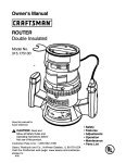
safety goggles (not glasses) that comply with ANSI
Z87 1 (shown on package), Everyday eyeglasses have
only impact resistant lenses They are not safety
glasses, Safety goggles are available at Sears retail
stores Glasses or goggles not in compliance with
ANSI Z87.1 could seriously hurt you when they break,
WEAR
YOUR
° Avoid hand positions where a sudden slip could cause
fingers or hand to move into a sawblade or other cutting too!
• Don't overreach., Always keep good footing and balance
o Push the workpiece against the rotation of the blade,
never feed material into the cutting tool from the rear of
the saw,
° Always push the workpiece all the way past the sawblade
° As much as possible, keep your face and body to one
side of the sawblade, out of line with a possible kick _
back or throwback
o Set the cutting tool as low as possible for the cut you're
planning
Avoid Accidental Starting.
° For dusty operations,
safety goggles
wear a dust mask along with
- Make sure switch is "OFF" before pltJgging saw into a
power outlet
, ,,11........
Whenever
Sawblade
....
,
i, ,,,1
Is Spinning
WARNING: Don't allow familiarity (gained from frequent use of your table saw) to cause a careless
mistake,. Always remember that a careless fraction
of a second is enough to cause a severe injury.
l
• Before actually cutting with the saw, watch it while it
runs for a short while if it makes an unfamiliar noise or
vibrates a lot, stop immediately
Turn the saw off
Unplug the saw Do not restart until finding and correcting the problem,
• Make sure the top of the arbor or cutting tool turns
toward the front of the saw
Keep Children
H,,
Away,
o Keep all visitors a safe distance from the table saw.
o Make sure bystanders are clear of the table saw and
workpiece
Don't Force Toot.
Before freeing jammed material.
o Turn switch "OFF"
Wait for aFImoving parts to stop
. Unplug the saw
° Check blade, spreader and fence for proper alignment
before starting again.
To avoid throwback
of cut off pieces.
° Use the guard assembly
To remove loose pieces beneath
the guard.
o Turn saw "OFF"
or trapped inside
° Remove switch key
- Wait for blade to stop before lifting the guard
Before Leaving The Saw.
- Turn the saw off
• Let the blade reach fu!t speed before cutting
° Wait for blade to stop spinning
° It will do the job better and safer at its designed rate
. Unplug the saw
• Make workshop child-proof Lock the shop Disconnect
master switches Remove the yellow switch key Store
it away from children and others not qualified to use
the took
o Feed the workpiece into the saw only fast enough to let
the blade cut without bogging down or binding
Additional
Crosscut
Safety Instructions
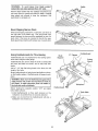
Rip Type Cuts.
o Never use the miter gauge when ripping
oUse a push stick whenever
inches from the blade
the fence is 2 or more
* When thru-sawing, use an auxiliary fence and push
block whenever the fence must be between 1/2 and 2
inches of the blade
o Never thru_saw rip cuts narrower than 1/2 inch (See
"Basic Saw Operations-Ripping
and Bevel Ripping"
sections,)
• Never rip anything shorter than 10" long
. When using a push stick or push block, the trailing end
of the board must be square A push stick or block
against an uneven end could slip off or push the work
away from the fence
• A Featherboard can help guide the workpiece (see
"Basic Saw Operation-Using Featherboards for ThruSawing" section)
o Always use featherboards for any non thru rip type cuts
(See "Basic Saw Operations - Using Featherboards for
NomThru Sawing" section,
Before Starting,
o To avoid kickbacks and slips into the blade, make sure
the rip fence is parallel to the sawblade
o Before thru-sawing, check the anti-kickback pawls
The pawls must stop a kickback once it has started.
Replace or sharpen antFkickback pawls when points
become dul} (See "Maintaining Your Table Saw - AntF
Kickback Pawls" section )
. Plastic and composition (like hardboard) materials may
be cut on your saw However, since these are usually
quite hard and sIippery, the anti-kickback pawls may
not stop a kickback Therefore, be especially careful in
your setup and cutting procedures,
While Thru-sawing.
• To avoid kickbacks and slips into the blade, always
push forward on the section of the workpiece between
the sawblade and the rip fence Never push forward on
the piece being cut off
Make From 3/4" Thick Solid Wood
24"
_'i
Kerfs About
5116" Apart_
Grain ----_
4.1/2,,-_-
Featherboard
it
Type Cuts.
o Never use the rip fence when crosscutting
o An auxiliary wood facing attached to the miter gauge
can help prevent workpiece twisting and throwbacks
Attach it to the slots provided Make the facing long
enough and big enough to support your work Make
sure, however, it wilt not interfere with the sawblade
guard
Before Starting.
* Use jigs or fixtures to help hold any piece too small to
extend across the full length of the miter gauge face
during the cut. This lets you properly hold the miter
gauge and workpiece and helps keep your hands
away from the blade
While Cutting
° To avoid blade contact, always hold the miter gauge
as shown in "Basic Saw Operations - Using The Miter
Gauge"
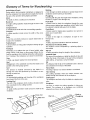
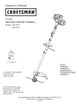
Glossary
of Terms for Woodworking
Anti-Kickback
Pawls
Device which, when properly maintained, is designed to
stop the workpiece from being thrown towards the front of
the saw at the operator during ripping operation
Arbor
The shaft on which a cutting tool is mounted
Bevel Cut
An angle cutting operation made through the face of the
workpiece,
Compound Cut
A simultaneous bevel and miter crosscutting operation
Crosscut
A cutting operation made across the width of the workpiece
Dado
A non thru cut which produces a square sided notch or
trough in the workpiece
Featherboard
A device which can help guide workpieces during rip type
operation
Freehand
Performing a cut without the use of fence (guide), miter
gauge, fixture, hold down or other proper device to prevent the workpiece from twisting during the cutting operation Twisting of the workpiece can cause it to be thrown
Gum
A sticky, sap based residue from wood products,
Heel
Misalignment of the sawblade such that the blade is not
parallel to the miter gauge groove,
Kerr
The amount of material removed by the blade in a
through cut or the slot produced by the blade in a nonthrough or partial cut
Kickback
An uncontrolled grabbing and throwing of the workpiece
back toward the front of the saw
Leading End
The end of the workpiece which, during a rip type operation, is pushed into the cutting tool first
Miter Cut
An angle cutting operation made across the width of the
workpiece
Molding
A non through cut which produces a special shape in the
workpiece used for joining or decoration,,
Ploughing
Grooving with the grain the length of the workpiece, using
the fence (A type of non-through cut)
Push Stick
A device used to feed the workpiece through the saw
during narrow ripping type operations which helps keep
the operator's hands well away from the blade
Push Block
A device used for ripping type operations too narrow to
allow use of a push stick,
Rabbet
A notch in the edge of a workpiece, (A type of nonthrough cut)
Resin
A sticky, sap based substance that has hardened,
Revolutions Per Minute (RPM)
The number of turns completed by a spinning object in
one minute
Rip Cut
A cutting operation along the length of the workpiece.
Sawblade Path
The area of the workpiece or table top directly in line with
either the travel of the blade or the part of the workpiece
which will be, or has been, cut by the blade.
Set
The distance that the tip of the sawblade tooth is bent (or
set) outward from the face of the blade,
Throw-Back
Throwing of pieces in a manner similar to a kickback,
Thru-Sawing
Any cutting operation where the blade extends
pletely through the thickness of the workpiece
Trailing End
The workpiece end last cut by the blade in a ripping operation
Workpiece
The item on which the cutting operation is being performed The surfaces of a workpiece are commonly
referred to as faces, ends, and edges
)ado or
Ploughing
Cut
Cut
Molding
Ri
\
Rabbet
Bevel Cut
Compound
Cut
com-
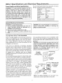
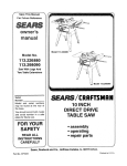
Motor Specifications
_ower Supply
and Electrical Requirements
The A-C motor used in this tool is a relay start, non-reversible type, having the following specifications:
and Motor Specifications
WARNING: To avoid electrical hazards, fire hazards or damage to the tool, use proper circuit protection.
Your tool is wired at the factory for
operation using the voltage shown. Connect toot
to a power line with the appropriate voltage and a
15-amp branch circuit. Use a 15-amp time delay
type fuse or circuit breaker. To avoid shock or fire,
if power cord is worn or cut, or damaged in any
way, have it replaced immediately.
i
,,u
General
1
Rated H P
1
Voltage
110-120
Amperes
1t 5
Hertz (Cycles)
60
Phase
Single
RPM
3450
Rotation of Shaft Counterclockwise
..............
Electrical
Connections
7
WARNING: Do not permit fingers to touch the ter- |
minals of plug when installing
or removing
the
plug to or from the outlet.
DANGER: To avoid electrocution:
1. Use only identical replacement parts when servicing, Servicing
should be performed
by a
qualified service technician.
2, Do not use in rain or where floor is wet.
This tool is intended for indoor residential use
.........
only.
110-120
Volt, 60 Hz. Tool Information
NOTE: The plug supplied on your toof may not fit into the
outtet you are planning to use Your local electrical code
may require slightly different power cord plug connections if these differences exist refer to and make the
If the grounding instructions are not completely understood, or if you are in doubt as to whether the tool is properly grounded check with a qualified electrician or service
)ersonnel.
proper adjustments per your local code before your tool
is plugged in and turned on
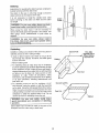
WARNING: If not properly grounded, this tool can
cause an electrical shock, particularly
when used
in damp locations, in proximity to plumbing, or out
of doors_ If an electrical shock occurs there is the
In the event of a malfunction or breakdown, grounding
provides a path of least resistance for electric current to
reduce the risk of electric shock This toot is equipped
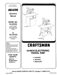
with an electric cord having an equipment-grounding conductor and a grounding plug, as shown,, The plug must
be plugged into a matching outlet that is properly
installed and grounded in accordance with all local codes
and ordinances
potential of a secondary
hazard,
hands contacting the sawblade.
such as your
3-Prong Plug
Properly
Grounded
3-Prong Outlet
\ J
Do not modify the plug provided, If it will not fit the outlet,
have the proper outlet installed by a qualified electrician
In
A temporary adapter may be used to connect this plug to
a 2-prong outlet as shown if a properly grounded three
prong outlet is not available,. This temporary adapter
should be used only until a properly grounded three
prong outlet can be installed by a qualified electrician
The green colored rigid ear', lug or the like, extending
from the adapter must be connected to a permanent
ground such as a properly grounded outfet box
111
G!ounding
Prong
Grounding
Improper connection of the equipment-grounding
conductor can result in a risk of electric shock The conductor with insulation having an outer surface that is green
with or without yellow stripes is the equipment-grounding
conductor If repair or replacement of the electric cord or
plug is necessary, do not connect the equipment-grounding conductor to a live terminal
Lug
_
Make sure this
Is Connected
to a Known
Ground
2-Prong
Outlet
NOTE: The adapter illustrated is for use only if you
already have a properly grounded 2-prong outlet
7
Motor Specifications
and Electrical
Requirements
(continued)
CAUTION: To avoid motor damage, this motor
should be blown out or vacuumed frequently to
prevent sawdust buildup which will interfere with
normal motor ventilation,
1 Frequent "blowing" of fuses or tripping of circuit breakers may result if:
a Motor is overloaded - Overloading can occur if you
feed too rapidly or if saw is misaligned
b, Motor circuit is fused differently from recommendations - Always follow instructions for the proper fuse/
breaker
Do not use a fuse/breaker of greater
capacity without consulting a qualified electrician
c Low voltage - Although the motor is designed for
operation on the voltage and frequency specified on
motor nameplate, normal loads will be handled
safely on voltage not more than 10% above or below
the nameplate voltage
Heavy loads, however,
require that voltage at motor terminals equals the
voltage specified on nameplate,
2. Most motor troubles may be traced to loose or incorrect connections, overloading, reduced input voltage
(such as small size wire in the supply circuit) or to
overly long supply circuit wire, Always check the connections, the load and the supply circuit whenever
motor fails to perform satisfactorily Check wire sizes
and length with the Wire Size Chart below
Wire Sizes
NOTE: Make sure the proper extension cord is used and
is in good condition
The use of any extension cord will
power To keep this to a minimum
heating and motor burn-out, use
determine the minimum wire size
cord
cause some loss o!
and to prevent overthe table shown to
(AWG,) extension
Use only 3-wire extension cords which have 3-prong
grounding type plugs and 3-prong receptacles which
accept the tool's plug
Extension
Cord Length
Wire Sizes Required
for (A.W.G.)
0-25 Ft,
26-50 Ft
16
16
Table of Contents
.......
Section
Page
Warranty ................................................................................ 2
Safety Instructions For Table Saw ....................
2
Safety Signal Words ...............................................
2
Before Using The Saw ...........................
2
When Installing Or Moving The Saw ......................
2
Before Each Use ..........................................
3
To Avoid Injury From Jams, Slips Or Thrown Pieces
(Kickbacks Or Throwbacks)
..................................
3
Plan Ahead To Protect Your Eyes, Hands,
Face and Ears ............................................................... 4
Whenever Sawblade Is Spinning ..........................
4
Additional Safety Instructions
..........................
5
Glossary of Terms for Woodworking ............................ 6
Motor Specifications and Electrical Requirements ......... 7
Power Supply and Motor Specifications ..................... 7
General Electrical Connections ................................... 7
110-f20 Volt, 60 Hz Tool Information ......................... 7
Wire Sizes ....................................................................
8
Table of Contents ............................................................
9
Unpacking and Checking Contents ......................
10
Tools Needed ...................................
10
Unpacking .................................................
List of Loose Parts ..........................................
Loose Paris ...........................................
10
11
11
Assembly ..............................................
12
Installing Handwheels and Bevel Pointer ............... 12
Assembling Steel Legs ..............................
12
Mounting Your Saw .......................................
13
Assembling Table Extensions .................................... 14
Installing Rip Fence Guide Bars and Switch Box , ,15
Aligning Extensions ................................................
17
Checking Table Insert ...........................................
18
Installing Blade Guard ................................
19
Getting to Know Your Table Saw ................................. 21
Safety Instructions for Basic Saw Operations ............ 24
Before Each Use
.......................................
24
To Avoid Injury From Jams, Slips Or Thrown Pieces
(Kickbacks Or Throwbacks) ..................................
24
Whenever Sawblade Is Spinning ............................ 25
Work Feed Devices ...............................
26
Push Stick .................................................................
26
Section
Page
Push Block .................................
26
Auxiliary Fence ..............................................
27
Basic Saw Operations ........................
28
Using the Miter Gauge .....................
28
Additional Safety Instructions for Crosscutting ........ 28
Crosscutting ...................................................
28
Repetitive Crosscutting ...................................
29
Miter Crosscutting ............................
30
Bevel Crosscutting
...................................................
30
Compound Crosscutting ......................................
30
Using the Rip Fence ..........................................
31
Addilionai Safety Instructions for Rip Cuts ............. 31
Ripping ..............................................
31
Bevel Ripping Narrow Work ..........................
33
Using Featherboards for Thru-Sawing
............
33
Using Featherboards for Non Thru-Sawing
.......
34
Resawing ..................................................................
34
Dadoing ....................................
35
Rabbeting ...........................................
35
Ploughing and Molding ............................
36
Molding Cutting .....................................
36
Adjustments ....................................................
36
Miter Gauge .....................................................
36
Rip Fence ......................................
37
Self Aligning Spring Adjustment ..............................
37
Rip Fence Alignment Adjustment ..............
38
Adjusting Rip Scale Indicator ......................
38
Heeling Adjustment or Parallelism of Sawblade to Miter
Gauge Groove ...............................
39
Blade Tilt, or Squareness of Blade to Table ........ 40
Blade Elevation
..................................
42
Tilt and Elevation Mechanism
...........................
42
Maintaining Your Table Saw ...........................
43
Maintenance ...................................
43
Lubrication ......................................................
44
Sears Recommends the Following Accessories
Troubleshooting ........................................
General ........................................
Motor .................................................................
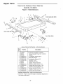
Repair Parts ........................................
......
45
45
45
46
47
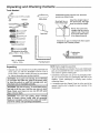
Unpacking and Checking Contents
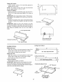
Tools
Needed
Combination
Square must be true. Check it's
accuracy as shown below.
Utility Knife
Draw light line on
board along edge
I
Phillips Screwdriver
Tape
Rule
straight edge are used to
align
They and
must
NOTE:the
Thesaw,
square
be accurate if the saw is
to be aligned properly,
i
LI
Medium Screwdriver
Select the straight edge of
314" thick board. This edge
must be perfectly straight.
\
Should be no gap or overlap here when square
is flipped over in dotted position,
Small Screwdriver
Combination
Wrenches
3!8 ino,7116 In,, 112 Ino,9/16 In.
_.,
Combination
Square
,_',- ',i '.;: : '._ '.I _,t
Hex "L" Wrenches
3/16 In., 1/8 In,
Framing Square
NOTE: Before beginning assembly:
o Check that all parts are included If you are missing any
part, do not assemble the saw Contact your Sears Service Center to get the missing part
Unpacking
1 Separate saw and all parts from packing materials and
check each one with the illustration and the "List of
Loose Parts" to make certain all items are accounted
for, before discarding any packing material
o Sometimes small parts can get lost in packaging mate*
riat Do not throw away any packaging until saw is put
together Check packaging for missing parts before
contacting Sears
WARNING: If any parts are missing, do not attempt
to assemble the table saw, plug in the power cord
or turn the switch on until the missing parts are
obtained and are installed correctly.
o A complete parts list (Repair Parts) is at the end of the
manual Use this list to identify the part number of the
missing part
WARNING: The saw is heavy° To avoid back injury,
get help to lift the saw. Hold the saw close to your
body. Bend your knees so you can lift with your
legs, not your back.
WARNING: For your own safety, never connect
plug to power source outlet until all assembly
steps are complete, and you have read and understand the safety and operating instructions.
10
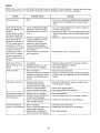
List of Loose Parts
Item
A
B
C
D
E
F
Part Name
Qtyo
Tabte Saw ............................................................
1
Rip Fence ..........................................
t
Miter Gauge .................................................
1
Blade Guard and Spreader ................................. !
Rip Fence Guide Bar, Rear ..................
1
Rip Fence Guide Bar with Rip Scale (Front)
,1
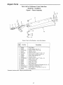
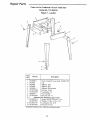
Loose
Item
G
H
J
K
L
M
Part Name
Table Extension 12 x 27 .........................
Side Stiffener ......................................
End Stiffener
.........................
Leg ............................................
Owners Manual ................................................
Bag of Loose Parts Labeled "Large Pads"
Qtyo
2
2
2
4
1
...... 1
Parts
A
E
F
_, _-
. ,,_,,_o
"_:__
B
K
C
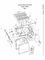
Open loose parts bag labeled "Large Pads", Check to
see that the following items are included
o Bag labeled "Guard"
• Blade Wrenches
• Bag labeled "Legs"
o Bag labeled "Table Extensions"
• Corner Supped Brackets .........................................
° Handwheels .....................................................................
4
2
o Bag labeled "Guide Bars"
• Wire Tie .....................................................
1
• Bag labeled "Miscellaneous"
• Bag labeled "Base"
11
......................................
2
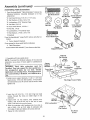
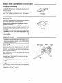
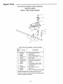
Assembly
Installing
.................
Handwheels
'"
........
i,,i
=
and Bevel Pointer
*2
Pan Head Screws, 10 - 32 x 5/8" Long
*2
"1
1
Lockwashers, #10 External Type
Par} Head Screw Type "T" 8-32 x 3/8 Long
Bevel Pointer
PH.....,.H ..,=......
=
Type "T" 8-32 x 3/8 In.
Pan Head Screw
10-32 x 5/8 In.
Pan Head Screw
1 From the bag labeled "Miscellaneous" remove only the
following hardware:
.....
O
Handwheel
#10 External
Lockwasher
Bevel Pointer
From the bag labeled "Large Parts" remove only the
following:
2 Handwheels
Items marked with asterisk (*) are shown actual size
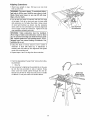
2, Fasten bevel pointer to cradle assembly with 8-32 x 3/8
screw, as shown. Adjustment of the pointer may be necessary later
Lockwasher
3 Line up flat spots on shaft and handwheel, push
handwheel onto shaft.. Install screw and !ockwasher to
lock handwheel
wheel
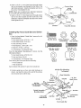
Assembling
Screw
on shaft. Repeat for the other hand-
Bevel Pointer
/
Elevation
Handwheel
Tilt
Handwheel
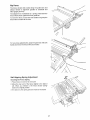
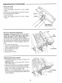
t From the bag labeled "Legs" remove the following
hardware:
"16 Truss Head Screws, 1/4-20 x 1/Z' long
1/4-20 x 112In
russ Head Screw
1/4" External Type
1/4 In. External
1/4-20
Hex Nut
Lockwasher
Q
"I6 Hex Nuts, 1/4-20
*8
Screw
0©
Steel Legs
"16 Lockwashers,
Pan Head
Hex Nuts, 3/8-16
4 Leveling Feet
From among the loose parts find the following:
4 Legs
2 End Stiffeners
3/8 -16 Hex Nut
Leveling Foot
2 Side Stiffeners
Leg
items marked w{th asterisk (*) are shown actual size
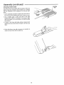
2 Assemble the legs as shown
insert the truss head screws through the holes in the
legs, then through the holes in the side and end stiffeners
Stiffener
Legs must be assembled on top of stiffeners
3 Install the Iockwashers
Side Stiffeners'_
.,,j End Stiffeners
Screw on the nuts hand tight.
4 Instal! leveling feet through hotes in bottom of legs as
shown.
5 Adjust teveling feet as follows:
a Move saw to desired location..
b. With 9/16" wrench loosen bottom nut
c Back off top nut by"hand
d Raise or lower foot by adjusting bottom nut using
9/16" wrench..
e.. Snug top nut against inside of leg by hand..
1/4-20
Hex Nut
f Tighten all four bottom nuts using 9/16" wrench
Lockwasher
Leveling
12
Foot ----_
Truss Head
Screw
Hex Nuts
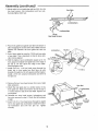
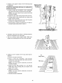
Mounting
Your Saw
1 From the bag labeled "Base"
hardware:
remove the following
*4
Hex Head Screws, 5/16-18 x 1-I/8" Long
*4
Hex Nuts, 5/16-18
*4
Lockwashers, 5/16" External Type
*8
Fiat Washers, tl/32
5t16-18 x 1-1/8 In
Hex Head Screw
5/16-18
Hex Nut
x 11/16 x 1/16
items marked with asterisk (*) are shown actual size
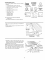
2 Place the saw upside down onto a smooth piece of
cardboard or heavy paper, on the floor, so the saw is
resting on the table top
5/16 In External
Lockwasher
11/32 LD.
Flat Washer
WARNING: The saw is heavy. To avoid back injury,
get help to lift the saw. Hold the saw close to your
body. Bend your knees so you can lift with your
3. Place legs on saw so that holes in saw base and leg
set line up and trim label is facing front. Legs will overhang base in rear
4. Install screw, washers, lockwasher and nut as shown
5 Tighten all leg assembly
this time
Cardb,
and mounting hardware at
Hex
Leg Set
Flat Washer
End Stiffener
Flat Washer
Hex Head Screw
Saw Base
NOTE: For clarity, later manual
show leg set attached
illustrations
may not
Bench Mounting
If you do net use the legset and prefer to mount the saw
on a bench, make sure that there is an opening in the top
of the bench the same size as the opening in the bottom
of the saw so that the sawdust can drop through Recommended working height is 33 to 37 inches from the top of
the saw table to the floor
12
14-3/4
1/2--,--
_l
Front of Saw
NOTE: All dimensions
13
in inches
Assembly
Assembling
(continued)
Table
....
.................
,,,
O
Extensions
1 From the bag labeled "Table Extensions" remove the
following hardware: (Quantity indicated is for two
extensions)
Hex Head Screw
21_41,D.
Flat Washer
0 @Q
*8 Hex Head Screws, 5/16-18 x 1-1/4" Long
*8 Flat Washers, 21/64 x 5/8 x 1/16
*8 Lockwashers. 5/16" External Type
5/16-18
Hex Nut
*8 Hex Nuts, 5/16-18
"10 Truss Head Screw, 1/4-20 x 1
17/64 I,D.
Flat Washer
"10 Hex Nut, 1/4-20
"10 Lockwashers,
i
5/16 In External
Lockwasher
©
114 In External
Lock'washer
Hex Nut
1/4 External Type
*4 Flat Washers, 1/7/64 x 3/4 x 1/16
2 Brackets
Truss Head Screw
From the bag labeled "Large Parts" remove only the following:
4
Bracket
Comer Support Brackets
From among the loose parts find the following:
2 Table Extensions
s°ppc
items marked with asterisk (*) are shown actual size
17/64 I.D.
Flat Washer
2 Assemble with saw upside down
NOTE: To protect the finished surfaces of the saw and
extensions, lay a piece of heavy paper or cardboard on
the floor..
WARNING:
Stock
table
extensions
must
\
\
Corner
1/4-20
Hex Nut
_._\
/
(_
support
be
Bracket ----__
installed. They help support the fence guide bars.
An unsupported
guide bar can twist. Twisted
guide bars can misalign fence. A misaligned fence
can cause binding or kickback. You could be hit or
cut,
k'
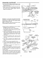
3 Install corner support brackets, 1/4-20 x 1 inch truss
head screws, 17/64 inch flat washers, 1/4 inch external Iockwashers and 1/4-20 hex nuts as shown, Hand
_'-4z.z_
Lockwasher
Table
This Edge Toward Table
tighten onty
4 insert four (4) 5/16-18 x 1-1/4 inch long hex head
screws through the holes on inside edge of one
extension
5/16-18
5 Instal! 21/64 ID fiat washer, 5/16 external lockwasher, and 5/16-t8 hex nut on the end of each
screw Just start nut on end of screw
6 Slide the extension with hardware into four slots in
side of table Line up front edge of extension with
front edge of table and tighten all screws and nuts
7 Repeat for other extension
Hex Nut _
51'16Lock'washer
21/64 I.D.
Flat Washer
Hex Head
Screw
t4
8 Inserta 1/4-20x 1 trussheadscrewthroughbottom
hole in the bracket,andthroughthefirstholein the
righthandextension.Installa lockwasher
andnuton
thescrewHandtightenthenut
NOTE:Whensawis upsidedown,righthandextension
is onthe leftsidewhenfacingfrontofsaw
9 Inserta 1/4-20x 1 trussheadscrewthroughbottom
holein the other bracket and the fourth hole of the
extension
j
Front1/4-20
of Saw
Hex Nut1/4
_ ¢._----
Lockwasher
Install a Iockwasher and nut on the screw
Hand tighten the nut.
1st Hole
Bracket
Installing
Rip Fence
Guide
Truss Hd. Screws
G
Bars and Switch
Box
1. From the bag labeled "Guide Bars" remove the following hardware:
*3 Hex Head Screws, 5/16-18 x 1-t/2
5/16-18 x 3/4
Hex Hd. Screw
5/16 In. External
Lockwashers
*3 Hex Head Screws, 5/16-I8 x 1
5/16 In.
Hex Jam Nut
*6 Hex Jam Nuts, 5/I6-18
*4 Flat Washers, 21/64 x 5/8 x 1/16
*3 Spacers, 3/4 dia, x 1/2 long
From the bag labeled "Miscellaneous"
following hardware:
5/16-18 x 1 In.
Hex Hd. Screw
5116-18 x 1-1/2 In
Hex Hd. Screw
*6 Lockwashers, 5/16 External Type
remove only the
*2 Hex Head Screws, 5/16-18 x 3/4
*2 Hex Jam Nuts, 5/16-18
*4 Lockwashers, 5/t6 External Type
21164 In.
Washer
From among the loose parts find the following:
1 Front Guide Bar
1/2 In. Spacer
1 Rear Guide Bar
Items marked with asterisk (*) are shown actual size
8th Slot (For Mounting
2. Position guide bars on floor and install hardware as
shown,. Just start the nuts on the end of the screws,
do not screw nuts on all the way,
To Bracket)
/
• FI_
wasner.._
(For Mounting __'_
ToBracko,
1-112 ln.Hex
Head Screw
,
Hex Nut
2rid Slot
Rear Guide Bar
¢
_
__
3rd Slot
l
__--_
t_'_
._
/
1st SIo_t I Spacer
Front Guide Bar
15
1 In Hex
Head'Screw
Flat Washer
Assembly
(continued)
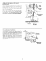
3 Mount switch to front guide bar with two 5/16-!8 x 3/4
hex head screws, tour lockwashers and two nuts_
Securely tighten both nuts
Hex Nuts
,,
_'_
_
1
Lockwashers
Loekwashers
3/4 In.
Hex Head Screws
4 Place front guide bar against saw table and drop it in
place engaging the screws in the slots, Make sure the
spacers are between the front guide bar and the
table
5 End of front guide bar must be 7-5/16 inch from side
of saw table, This is important so that rip fence indicator can be aligned
Lockwasher
Hex Nut
1-1/2 In.
Hex Head
6 With the blade of your combination square set to 1/4
inch, gauge and adjust front guide bar so the edge of
the bar is 1/4 inch above the edge of the table,
Securely tighten nuts,
7 Install 5/16-18 x 1-1/2 hex head screw through the
fourth slot in front guide bar (that lines up with
bracket), through the 1/4 inch spacer and the bracket,
Install a 5/16 inch external lockwasher and 5/16-t8
Screw
@
7-5!16 |no
hex jam nut,
8. Remove the two truss head screws from rear of right
table extension,
Hex Nut
9 Attach the rear guide bar in a similar manner to the
front guide bar Make sure that the end of the bar is
11 inches from the side of the saw table, Spacers are
not required
10 Reinstall two truss head screws, tockwashers and
hex nuts removed in step 8. Check that all hardware
is tight
11 insert 5/16-18 x 1 hex head screw through the eighth
slot in rear guide bar and bracket, Install 5/16 external Iockwasher and 5/16 hex jam nut Tighten
securely
Lockwas her'
Truss Head
Screws
1 In. Hex Head
Screws
16
t In,
Hex Head
Screw
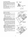
Aligning
Extensions
1. Stand saw upright on legs
then up onto feet,
Roll saw over onto front
WARNING: The saw is heavy. To avoid back injury,
get help to lift the saw. Hold the saw close to your
body. Bend your knees so you can lift with your
legs, not your back.
2 Line up the front edge of extension with the front edge
of the table Pul! up on front and rear of sheet metal
side extension so it is higher than table Using a block
of wood and hammer as shown, tap the extension
down until it is even with table top Recheck alignment
of front edge of table and extension Tighten front and
rear extension mounting nuts only,
WARNING:
Table
extensions
must
Line Up Front
Of Extension
be installed,
Front edge of table and extensions must be lined
up. An uneven front edge can twist the fence guide
bar. Twisted guide bars can misalign fence. A misaligned fence can cause binding or kickback. You
could be hit or cut.
3 Using the block of wood, check to see if center of
extension is flush with table top If adjustment is
needed, push the table top into alignment and tighten
center two mounting nuts
4, Repeat steps 2 and 3 to atign the other extension
1 From the bag labeled "Large Parts" remove the following hardware;
1 Wire Tie
Tie
2 Use a hammer to lightly tap the pointed tab on the wire
tie into the hole provided on side of cabinet Route
motor cord from inside cabinet through the wire tie
Secure cord in wire tie Keep any extra cord on outside
of cabinet Do not push extra cord inside cabinet,,
Extension
Removed for
Picture Clarity
Wire Tie
17
Assembly
Checking
(continued)
.....
Leveling
Tab
Table Insert
The table insert must be flush with the surface of the saw
table to keep the workpiece from hanging up or binding
with the sawbtade as the workpiece is cut by the sawblade,
1 Lower sawblade beneath the table insert and check to
be sure the screw fastening the insert in place is snug
Edge
2 Use a straight edge to check near each of the eight
leveling tab positions to determine if the insert is flush
with the surface of the saw table at all eight leveling
tab positions
3. tf insert is not flush with table surface, loosen insert
fastening screw and pull insert forward to lift from saw
table
4, Bend with pliers or tap with a hammer, as required, to
make the insert flush with the table top,
.
\
\
18
/--
Installing
Blade Guard
1. From the bag Iabeled "Guard" remove the following
hardware:
*2
*2
Truss Head Screws, t/4-20 x 5/8" Long
Socket Head Set Screws, 1/4-20 x 7/8" Long
*4
Fiat washers, 17/64 x 9/16 x 3/64
*2
Hex Nuts 1/4_20
*4
Lockwashers,
*2
Wing Nuts, 1/4-20
*2
Square Nuts, 1/4-20
X
1/4-20 Head
7/8
Socket
8 In
Truss Head Screw
Q
1/4 ExternalType
Set Screw
1/4 In,, External
Lockwasher
1/4-20
114-20Hex Nut
©
17164I°D.
Square Nut Flat Washer
1/4-20 Wing Nut
1 Spreader Support
1 Spreader Bracket
1 Spreader Clamp
Spreader Support
Spreader Bracket
From among the loose parts find the following:
1 Blade Guard
Items marked with asterisk (*) are shown actual size
2, Make sure the blade is all the way up and square with
table,
3, Position spreader support on rod until it is even with
the end of the rod.
\
Blade
Square
With Table
Even With Rod
=
i
...........
4 Assemble the 7/8 inch long set screws, nuts, lockwashers and washers to the spreader support bracket
and slip the nuts into the slot in the spreader support,
5 Finger tighten only the hex nuts
NOTE: Be sure to put the socket head set screw through
the slot shaped holes in the spreader bracket (see itlustration)_ This allows the guard and spreader to be Iined
up with the blade Be sure the socket end of the set
screw is at the hex nut end of the assembly,
Holes Up
Round Hole
On Side
- Leckwasher
ex Nut --='_
19
Assembly
(continued)
6 Lay a piece of flat straight wood and a square on saw
table and rotate the spreader support until the bracket
is aligned with square.
7 Make sure end of support, bracket and rod are even
Using a 1/8 inch hex "L" wrench, tighten the set screws
only Check that the spreader support cannot be
rotated on the spreader rod
_port
_'_And Bracket To
Be Even With
End Of Rod
Tighte_
Setscrew Only t
Important:
be parallel
piece will
binding or
To work properly, the spreader must always
to the sawblade and adjusted so the cut workpass on either side of the spreader without
skewing to the side
Space Equal to Approx.
3 Thicknesses of Paper
Wood
.
Blade
NOTE: The spreader is thinner than the width of the kerr
by approximately six thicknesses of paper
8 Make two folds in a smaII piece (6 x 6 inch) of ordinary
newspaper making three thicknesses.
The folded paper will be used as "spacing gauge"..
9 Raise blade to maximum height and make sure blade
is square to the saw table.
10. Install the spreader clamp using t/4-20 x 5/8 truss
head screws, lockwashers, and wing nuts Place
spreader between spreader clamp and bracket. Move
spreader forward until all three are in line. Tighten
wing screws
11 Lilt up both anti-kickback pawls Insert set screw
wrench or a pencil into notches to hold the pawls out
of the way
12. Lay a piece of straight flat wood against the sawblade Insert folded paper between spreader and strip
of wood.
13 Make sure the hex nuts underneath are loose
Looking Down on Saw
/l
Antikickback
Pawls
Piece of
Straight Wood
Hold Wood
Tightly Against
Blade
Three
Thicknesses
Of Paper \
14 Hold the spreader tightly against the wood and make
sure the wood is against the sawblade Tighten the
hex nuts.
This will align the spreader in the middle of the cut
(kerf) made by sawbtade
NOTE: To remove the guard for non-through cuts, loosen
the wing nuts and slide the guard back and upward off
the spreader bracket Do not disturb the setting of the
spreader bracket
When replacing the guard, slide the spreader down and
forward between the spreader clamp and spreader
bracket until it rests as shown, make sure wing nuts are
tightened securely This lets yell remove and replace the
guard without disturbing the spreader alignment.
Hold Spreader
Tightly Against Wood
Clamp
Wing Nut
Lock'washer
2O
Screw
Spreader
Bracket
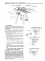
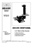
Getting
to Know Your Table Saw
8 Sawblade
......
6 Blade Guard
5 Miter Gauge
4 Rip Fence
7 Table Insert
9 Exacti-Cut
3 Tilt
Handwheel
2 Elevation
Handwheel
Switch
1, On-Off
Switch.
the blade guard is correctly installed and operatI CAUTtON: Before turning switch "ON", make sure
ing properly.
The On-Off Switch has a locking feature_ This feature is
intended to help prevent unauthorized and possible hazardous use by children and others
A Remove key from bag labeled "Miscellaneous"
insert into switch.
and
B To turn saw ON, stand to either side of the bJade,
never in line with it, insert finger under switch lever
and pull end of lever out
After turning switch ON, always allow the blade to
come up to full speed before cutting. Do not cycle
the motor switch on and off rapidly, as this may
cause the sawblade to loosen. In the event this
should ever occur, allow the sawbIade to come to a
complete stop and retighten the arbor nut normally,
not excessively
Never leave the saw while the
power is "ON"
CTo turn saw OFF, PUSH lever in Never leave the
saw until the cutting too} has come to a complete
stop
©
D To lock switch in OFF position, hold switch IN with
one hand, REMOVE key with other hand
WARNING: For your own safety, lower blade or
other cutting tool below table surface. (if blade is
tilted, return it to vertical, 90 °, position.) Always
lock the switch "OFF". When saw is not in use,
remove key and keep it in a safe place. Also, in the
event of a power failure (all of your lights go out)
turn switch off, lock it and remove the key. This
will prevent the saw from starting up again when
the power comes back on.
21
Getting to Know Your Table Saw (continued)
.....................
5. Miter Gauge...head
is locked in position for crosscutting or mitering by tightening the lock knob
Always lock it securely when in use
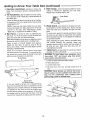
2. Elevation
Handwheel...elevates
or lowers the
blade Turn clockwise to elevate, counterclockwise to
lower
3, Tilt Handwheel...tilts
the blade for bevel cutting
Turn clockwise to tilt toward left, counterclockwise to
Lock Knob
tilt toward right.
When the blade is tilted to the left as far as it will go,
it should be at 45 ° to the table and the bevel pointer
should point to 45 °
NOTE: There are limit stops inside the saw which
prevent the blade from tilting beyond 45 ° to the left
and 90 ° to the right. (See "Adjustments" section
"Blade Tilt, or Squareness of Blade to Table")
6. Blade Guard...must
always be in place and working properly for all thru-sawing cuts That is, all cuts
where the blade cuts completeIy through the workpiece
To remove the guard for special operations, loosen
the wing nuts and slide the guard back and upward
off the spreader bracket Do not disturb the setting of
the spreader bracket
When replacing the guard, slide the spreader down
and forward between the spreader clamp and
spreader bracket until the bottom and rear edges of
all three are even Make sure both wing nuts are
hand tightened securely
7. Table Insert..ois removable for removing or installing blade or other cutting tools
4, Rip
Fence_Js locked in place by tightening the
lock knob To move the fence, loosen the knob and
grasp the fence with one hand at the front
Holes are provided in the rip fence for attaching a wood
facing when using the dado head, or molding head
Select a piece of smooth straight wood approximately 3/4 inch thick, at least as long as the rip
fence, and at least 7-1/2 inches wide (high) to permit
clamping of featherboards
Attach it to the fence with the three round head
#10 wood screws 2 inches long. To remove the facing, loosen the screws, slide the facing forward and
pu_l the screws through the round hotes.
Wood Facing
WARNING: To avoid injury from accidental
start, l
turn switch "OFF" and remove plug from power
source before removing insert.
A Lower the blade below the table surface
B Raise blade guard
C Loosen insert screw
D Lift insert from front end, and pull toward front of
saw,
WARNING: Never operate saw without the proper
insert in place. Use the sawblade insert when sawing. Use the combination
dado molding
insert
when using a dado or molding head.
Round Head
#10 Wood Screws
If you are making a rip type cut in material thinner
than 3/16 inch while the fence is positioned over the
depressed area of table extension, the facing should
be attached to the fence so that the bottom edge
touches the top surface of tf3e extension _nthis case,
the facing must be shorter than the fence This will
prevent thin material from sliding under the rip fence
22
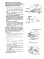
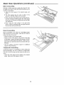
8. Removing
and Installing
Sawblade
WARNING: To avoid injury from accidental start, turn
switch "OFF" and remove plug from power source
outlet before removing or installing sawblade.
Pull To Loosen
Push To Tigh_en
A Remove insert.
B. Remove wrenches from bag labeled "Large Parts"
C Place open end arbor wrench on flat surfaces of saw
arbor and closed end arbor wrench on nut Position
wrenches as shown, holding your hands well above
blade
DWith arbor wrench against table, pull wrench on
arbor nut forward to loosen nut
E To tighten nut, hold arbor wrench against rear of
table, push arbor nut wrench toward rear.
NOTE: When installing the blade, make sure the teeth
are pointing toward the front of the saw and that the
blade and collars are clean, and free from any burrs
The hollow side of the collars must be against the
blade
Flat Surfaces
_'_Z"'_"J'_
Always tighten the arbor nut securely.
F To replace insert Place insert into opening in table
and push toward rear of saw to engage spring clip
and until keyslot in insert will drop over screw
Tighten screw Do not tighten screw to the point
where it will dellect the insert,
Collar
_
/
7\
Hex Nut
Toot.
PointingTo
Front of Saw
WARNING: To avoid injury from a thrown workpiece,
blade parts, or blade contact, never operate saw
without the proper insert in place. Use the sawblade
insert when sawing. Use the proper size dado/molding insert for dado blades and molding heads°
\"-,,,_._-f
Shown With Hold Down Clamp
9. Exact-I-Cut
The "yellow" plastic disk embedded in the table in front
of the sawblade, is provided for marking the location of
the "sawcut" (kert) on the workpiece
Check disk location: if it is above table surface, place a
piece of hardwood on top of it and tap it down with a
hammer.
Marking the Exact-l-Cut:
A With blade 90 ° (square to table) and miter gauge in
left groove, cross cut a piece of wood holding the
wood firmly against miter gauge.
Blade Guard Not Shown
For Picture Clarity
B Pull miter gauge back until freshly cut edge of wood
is over disk. Using a sharp pencil, mark a line on
disk at freshly cut edge of wood
C With miter gauge in right hand groove, follow same
procedure and mark another line on disk
\
D These lines indicate the "path" of the cut (kerr) made
by the sawblade.
E When cutting the workpiece, line up mark on workpiece with line on disk
Use the hold-down clamp (optional accessory) on the
miter gauge for greater accuracy
23
In
Safety Instructions
Before
for Basic Saw Operations
...........
Each Use
. Replace damaged or missing parts before using the
saw again
Inspect your saw.
• To avoid injury from accidental starting, tum the switch
off, unplug the saw, and remove the switch key before
raising or removing the guard, changing the cutting
tool, changing the setup, or adjusting anything,
. Use the sawblade guard, spreader and anti-kickback
pawls for any thru-sawing (whenever the blade comes
through the top of the workpiece). Make sure the antikickback pawls work properly Make sure the spreader
is in line with sawbladeo
. Check for alignment of moving parts, binding of moving parts, breakage of parts, saw stability, and any
other conditions that may affect the way the saw
works.
• Remove adjusting keys and wrenches. Form a habit of
checking for and removing keys and wrenches from
table top before turning saw on,
• If any part is missing, bent or broken in any way, or any
electrical part does not work properly, turn the saw off
and unplug the saw.,
• Make sure all clamps and locks are tight and no parts
have excessive play
.......
To Avoid
Injury
From
Jams,
Slips
Or Thrown
Pieces
(Kickbacks
, , ,,i ,i,,,11111,,,,,,,,,,,,i
Or Throwbacks)
• Use the right tool Don't force too! or attachment to do
a job it was not designed for
Inspect Your Blade.
• Choose the right blade or cutting accessory for the
material and the type of cutting you plan to do,
Dress for safety
• Do not wear loose clothing, gloves, neckties or jewelry
(rings, wrist watches). They can get caught and draw
you into moving parts
=Use The Right Tool, Don't force tool or attachment to
do a job it was not designed for
° Never use grinding wheels, abrasive cutoff wheels,
friction wheels (metal cutting blades) wire wheels or
buffing wheels They can fly apart explosively..
• Wear nonslip footwear,
° Tie back long hair.
• Cut only wood, wood like or plastic materials, Do not
cut metal,,
° Roll long sleeves above the elbow
• Noise levels vary widely, To avoid possible hearing
damage, wear ear plugs or muffs when using table
saw for hours at a time.
• Choose and inspect your cutting tool carefully:
-To avoid cutting tool failure and thrown shrapnel
(broken pieces of bIade), use onty t0" or smaller
blades or other cutting tools marked for speeds of
5000 rpm or higher
° Any power saw can throw foreign objects into the
eyes This can result in permanent eye damage Wear
safety goggles (not glasses) that comply with ANSI
Z87 1 (shown on package) Everyday eyeglasses have
only impact resistant lenses They are not safety
glasses Safety goggles are available at Sears retail
stores Glasses or goggles not in compliance with
ANSI Z871 could seriously hurt you when they break,
- Always use unbroken, balanced blades designed to
fit this saw's 5/8 inch arbor
-When thru-sawing (making cuts where the blade
comes through the workpiece top), always use a I0
inch diameter blade This keeps the spreader in closest to the blade
WEAR
YOUR
- Do not over tighten arbor nut Use arbor wrenches to
"snug" it securely
- Use only sharp blades with properly set teeth Consult a professional blade sharpener when in doubt
• For dusty operations,
safety goggles
- Keep blades clean of gum and resin
- Never use the saw without the proper blade insert,
Inspect your work area.
o Keep work area clean
° Cluttered areas and benches invite accidents,
must not be slippery from wax or sawdust
wear a dust mask along with
Inspect your workpiece.
• Make sure there are no nails or foreign objects in the
part of the workpiece to be cut
Floor
• When cutting irregularly shaped workpieces, plan your
work so it will not slip and pinch the blade:
o To avoid burns or other fire damage, never use the
saw near flammabte liquids, vapors or gases
. A piece of molding for example, must lie flat or be held
by a fixture of jig that will not let it twist, rock or slip
whiIe being cut Use jigs or fixtures where needed to
prevent workpiece shifting
o To avoid injury, don't do layout, assembly, or setup
work on the table while blade is spinning tt could cut
or throw anything hitting the blade
• Use a different, better suited type of tool for work that
can't be made stable
Plan your work
° Plan ahead to protect your eyes, hands, face, ears
24
Planyour
cut.
• To avoid kickbacks and throwbacks which occur when
Plan the way you will push the workpiece through.
o Never pull the workpiece through,, Start and finish
the cut from the front of the table saw
a part or all of the workpiece binds on the blade and is
thrown violently back toward the front of the saw:
- Never cut Freehand. Always use either a rip fence,
miter gauge or fixture to position and guide the work,
so it won't twist or bind on the blade and kickback
° Never put your fingers or hands
sawblade or other cutting tool
o Never reach in back of the cutting tool with either
hand to hold down or support the workpiece, to
remove wood scraps, or for any other reason
- Make sure there's no debris between the workpiece
and its supports
• Use extra caution with large, very small or awkward
workpieces
oAvoid hand positions where a sudden slip could cause
fingers or a hand to move into a sawblade or other cutting toot
• Don't overreach Always keep good footing and balance
• Use extra supports (tables, saw horses, blocks, etc)
for any workpieces large enough to tip when not held
down to the table top, Never use another person as a
substitute for a table extension, or as additional support for a workpiece that is longer or wider than the
basic saw table, or to help feed, support or pull the
workpiece.
• Push the workpiece against the rotation of the blade,
never feed material into the cutting toot from the rear of
the saw
° Always push the workpiece all the way past the sawMade,,
o As much as possible, keep your face and body to one
side of the sawblade, out of line with a possible kickback or throwback
• Never confine the piece being cut off, that is, the piece
not against the fence, miter gauge or fixture Never
hold it, clamp it, touch it, or use length stops against it
It must be free to move If confined, it could get
wedged against the blade and cause a kickback or
throwback.
• Set the cutting tool as tow as possible for the cut you're
planning,
Avoid Accidental Starting.
° Make sure switch is "OFF" before plugging saw into a
power outlet
. Never cut more than one workpiece at a time
° Never turn your table saw "ON" before clearing everything except the workpiece and related support
devices off the table
Whenever
Sawblade
is Spinning
WARNING: Don't allow familiarity (gained from fre- I
quent use of your table saw) cause a careless mistake. Always remember that a careless fraction of
a second is enough
to cause a severe injury.
I
= Before actually cutting with the saw, watch it while it
runs for a short while, if it makes an unfamiliar noise or
vibrates a lot, stop immediately Turn the saw off
Unplug the saw Do not restart until finding and correcting the problem,
Before freeing jammed material.
Turn switch "OFF"
° Wait for all moving parts to stop
- Unplug the saw
. Check blade, spreader and fence for proper alignment
before starting again,
To avoid throwback
of cut off pieces.
o Use the guard assembly
To remove loose pieces beneath or trapped
the guard,
o Turn saw "OFF"
• Make sure the top of the arbor or cutting tool turns
toward the front of the saw
Keep Children
in the path of the
Away,
inside
• Remove switch key
° Keep all visitors a safe distance from the table saw
° Wait for blade to stop before lifting the guard
° Make sure bystanders are clear of the table saw and
workpiece
Don't Force Tool,
Before Leaving The Saw.
° Turn the saw off
• Wait for blade to stop spinning
• Let the blade reach full speed before cutting
. It will do the job better and safer at its designed rate
° Unplug the saw
o Make workshop child-proof Lock the shop Disconnect
master switches Remove the yellow switch key Store
it away from children and others not quatified to use
the tooI
. Feed the workpiece into the saw only fast enough to let
the blade cut without bogging down or binding
25
Work Feed Devices
....
...................
IIIII'1
........
--
Before cutting any wood on your saw, study all of the
"Basic Saw Operations"
Many people custom build their own jigs and fixtures
Jigs and fixtures are often designed for a particular cut
As you learn new table saw woodworking techniques,
you'll see that many types of cuts need different support
and feeding devices, known as jigs or fixtures. They can
help you make cuts more accurately. By helping to
steady the workpiece and keep you away from the blade,
they can help you safely use your saw for certain cuts..
You can use your table saw to easily make many jigs and
fixtures To get you started, we've included instructions
for some simple ones After you have made a few practice cuts, make up these jigs before starting any projects.
The use of these devices is explained in "Basic Saw
Operations" section.
.... u
Push
....
--,--=
Stick
Make the featherboard
wood.
Make the push stick using a piece of 1 x 2 x 3/4 thick
solid wood.
Slightly Less Than Thickness
3/4"
Of Workpiece Up To 3/8"
-_
F.
24"
Kerfs About
5/16" Apart
1-S/8"
Grain-----.
8"
!
in inches
... H..i...=..i...,.11
i
....
..,
Material for Push Block
Push Block
There are any number of ways to properly cut your workpieces to make a push block The following steps
describe one way you can make a push block.
-==
At Least12"_
Making the base:
3/8" Thick Plywood
Base
• Start with a piece of 3/8 inch plywood at least 5-5/8
inches wide or wider and 12 inches long or longer
o Make two ripcuts. Perform the first dpcut along the
side of the 3/8" wide strip Next, ripcut the 3/8" plywood
to a width of 5-1/8".
-._
At Least 12"_
o Crosscut the 3/8" plywood to 12" long,
3/4" Thick Plywood
Handle
. Crosscut a 2-1/2" piece off the 3/8" wide by 3/8" thick
strip and save this short piece for later.
. The next cuts wili create the 3/8" by 9-1/2" notch in the
base Mark the long edge of the board 2-1/2" from one
end Make a crosscut into the edge on the mark, stopping about 3/4" into the board Set the saw and rip the
width to 4-3/4" along the same edge as the stopped
crosscut,, Stop the ripcut where the two cuts intersect,
Turn off the saw and remove the bas_epiece The base
should now measure as shown
/
Finished
-4
4-1/2"-,-- ---,-F"- s"H
1/2"
NOTE: All dimensions
from a 8 x 24 x 3/4 thick solid
/
Base
Creating the Notch
3/8"
2-1,2,, t
These Edges
Must Be
Parallel
I
26
2 nd Cut
-f
_,t Least
5-5t8"
Making the handle:
- Miter crosscut a piece of 3/4 inch thick plywood to
shape and size shown:
NOTE: The mitered comers can be any size that looks
like the drawing (about 1-1/2" by 1-1/2"),
1-1/2"_._ /___
5"
1-1/2"
Putting it Together
• Using good quality woodworking glue, glue the 3/8" x
3/8" × 2-1/2" piece strip saved earlier to the base as
shown,
-_
12"
, ,_,.
IMPORTANT: Do not use nails or screws, This is to prevent dulling of the sawbtade in the event you cut into the
push block
o Position the handle at the center of the plywood base
as shown Fasten them together with glue and wood
screws
Glue Onty_
IMPORTANT: Make sure the screw heads do not stick
out from the bottom of the base, they must be flush or
recessed,, The bottom must be flat and smooth enough to
slide along the auxiliary fence you are now ready to
make
Plywood
Finished
Screw Head Must Be
Flush Or Recessed
Push
3/8" Plywood
Auxiliary
Handle
Base
Cutting Out the Base
Fence
Making the base:
30"
° Start with a piece of 3/8 inch plywood at least 5-1/2
inches wide or wider and 30 inches long or longer,
o Cut the piece to shape and size shown:
3E|-l!2r_L
3/8" Thick Plywood
Base
s /2
Making the side:
° Start with a piece of 3/4 inch plywood at least 2-3/8
inches wide or wider and 27 inches long or longer
Cutting Out the Side
• Cut the piece to shape and size shown:
Putting it together:
o Put the pieces together, as shown:
IMPORTANT: Make sure the screw heads do not stick
out from the bottom of the base, they must be flush or
recessed, The bottom must be flat and smooth enough to
rest on the saw table without rocking
_'=
3/4" Thick
Side
Plywood27"
_"_2_8
Finished Auxiliary Fence
j_.1._.__._..___..."
Plywood
L
This Face and
This Edge Must
Be Parallel
27
"
Basic Saw Operations
Using
.........
,
o An auxiliary wood facing attached to the miter gauge
can help prevent workpiece twisting and throwbacks.
Attach it to the slots provided. Make the facing long
enough and big enough to support your work. Make
sure, however, it will not interfere with the sawblade
guard.
the Miter Gauge
The miter gauge is used when crosscutting, miter cutting,
bevel cutting, compound miter cutting, dadoing and when
rabbeting across the end of a narrow workpiece.
° Use jigs or fixtures to help hold any piece too small to
extend across the full length of the miter gauge face
during the cut. This lets you properly hold the miter
gauge and workpiece and helps keep your hands away
from the blade..
the following safety precautions in addition to the
WARNING:
For yourof own
safety instructions
pagessafety,
2, 3, 4,always
5, 24 & observe
2&
Additional
Safety Instructions
for Crosscutting
Before Starting:
=Never use the rip fence when crosscutting
specifically instructed
While cutting:
• To avoid blade contact, always hold the miter gauge as
shown in the this section
except as
Crosscutting
Definition: A cutting or shaping operation
the width of a workpiece
made across
The graduations on the miter gauge provide ample accuracy for average woodworking
In some cases where
extreme accuracy is required, make a tdal cut and then
recheck it with a precision square, or protractor.
Sandpaper
NOTE: The space between the miter gauge bar and the
groove in the table is held to a minimum during manufacturing
For maximum accuracy when using the miter
always favor one side of the groove in the table
words, don't move the miter gauge from side
while cutting but keep one side of the bar riding
one side of the groove.
Always Support
Long Workpieces
gauge,
In other
to side
against
NOTE: Gluing a piece of sandpaper to the face of the
miter gauge head can help prevent the workpiece from
"creeping" while it is being cut
The miter gauge head is locked in position by twisting the
lock knob clockw{se Always tighten it securely when in
use,
[WARNING:
To avoid
blade contact
hold miter gauge
properly.
or kickback, 1
The miter gauge may be used in either of the grooves in
the table
When using the miter gauge in the left hand groove, hold
the workpiece firmly against miter gauge head with your
left hand, and grip the lock knob with your right hand
When using the miter gauge in the right hand groove,
hold the workpiece with your right hand and the lock knob
with your left hand
28
Crosscutting
(continued)
Lock
Knob
Slots are provided in the miter gauge for attaching an
auxiliary facing to make it easier to cut very tong or short
pieces_ Select a suitable piece of smooth wood, drill two
holes through it and attach with screws Make sure the
facing does not interfere with the proper operation of the
sawblade guard
Miter Gauge
k
Head
When cutting long workpieces, you can make a simple
support by clamping a piece of plywood to a sawhorse
(As seen on previous page.,)
Use the hold-down clamp (optional accessory) on the
miter gauge for greater accuracy°
Auxiliary Facing
I IM....
III'UU
Left Hand Removed
Repetitive Crosscutting
Stop Rod
For Clarity
Definition: Cutting a quantity of pieces the same length
without having to mark each piece.
A Use the stop rods (optional accessory shown) only
for cutting duplicate pieces 6 inches long and
longer,
B Follow all safety precautions and operational
instructions for cross cutting
When making repetitive cuts from a long workpiece,
make sure it is adequately supported
WARNING; Never use the rip fence as a direct
length stop because the cutoff piece could bind
between the fence and the blade causing a kickback.
©,When making repetitive cuts shorter than 6 inches,
clamp a block of wood 3" long to the table at desired
length to act as a length stop. Do not clamp directly
to the bottom edge of the table because the "swivel"
of the clamp will not grip properly Place a small
block of wood between the bottom edge of the table
and the '%" clamp
__
Work Support
Wood Block
f\\
workpiece,
when clamping the block make sure
that
the
end
of the
blockkickback
is well in
front twisting
of the sawWARNING: To
avoid
from
the
blade. Be sure it is clamped securely°
D Slide the workpiece along the miter gauge until it
touches the block hold the workpiece securely
against the miter gauge or clamp it with the holddown clamp (optional accessory shown)
E,Make the cut, turn the saw off, remove the piece
after the blade has stopped and before cutting the
next piece
29
/J
Basic Saw Operations
(continued)
Miter Crosscutting
Definition: Cutting wood at an angle other than 90 ° with
the edge of the wood. Follow the same procedure as you
would for crosscutting
A Adjust the miter gauge to the desired angle, and
lock it
B The miter gauge may be used in either of the
grooves in the table Make sure it is locked
C When using the miter gauge in the left hand groove,
hoId the workpiece firmly against the miter gauge
head with your Ieft hand, and grip the lock knob with
your right hand
D When using the miter gauge in the fight hand
groove, hold the workpiece with your right hand and
the lock knob with your left hand,
Bevel
Crosscutting
Bevel crosscutting is the same as crosscutting except
that the wood is cut at an angle ,other than 90 ° with the
bottom flat side of the wood,,
o Adjust the blade to the desired angle,
, Always use the miter gauge in the groove to the right
of the blade It cannot be used in the groove to the left
because the blade guard will interfere Hold the workpiece with your right hand and the lock knob with your
left hand
• Use the auxiliary fence/work
support of the workpiece
Compound
support
for additional
Crosscutting
Compound cutting is a combination of miter cutting and
bevet crosscutting
The cut is made at an angle other
than 90 ° to both the edge and the bottom flat side of the
wood,
o Adjust the miter gauge and the blade to the desired
angle .Make sure miter gauge is locked
30
o A featherboard can help guide the workpiece_ (See
"Basic Saw OperatiomUsing Featherboards for ThruSawing" section,)
Using the Rip Fence
Ripping, bevel ripping, resawing and rabbeting are performed using the rip fence together with the auxiliary
fence/work support, push stick or push block,
,Always use featherboards for any non thru-sawing rip
type cuts, (See "Basic Saw Operations-Using Featherboards for Non Thru-sawing" section)
Before Starting:
observe all safety precautions listed in manual and
I WARNING:
For your own safety, read and always
on saw.
Additional
Safety instructions
o To avoid kickbacks and slips into the blade, make sure
the rip fence is parallel to the sawblade
for Rip Cuts
• Before thru-sawing, check the anti-kickback pawls, the
pawls must stop a kickback once it has started,,
Replace or sharpen anti-kickback pawts when points
become dull
• Never use the miter gauge when ripping
• Use a push stick whenever
inches from the blade,
lhe fence is 2 or more
• When thru-sawing, use an auxiliary fence and push
block whenever the fence must be between 1/2 and 2
inches from the blade
° Plastic and composition (like hardboard) materials may
be cut on your saw, However, since these are usually
quite hard and slippery, the anti-kickback pawls may
not stop a kickback, Therefore, be especially careful in
your setup and cutting procedures,
• Never thru-saw rip cuts narrower than t/2 inch,
o Never rip anything shorter than 10" long,.
• When using a push stick or push block, the trailing end
of the workpiece must be square A push stick or block
against an uneven end could slip off or push the workpiece away from the fence,
While Thru-sawing:
o To avoid kickbacks and slips into the blade, always
push forward on the section of the workpiece between
the sawblade and the rip fence Never push forward on
the piece being cut off
Always Support Long
Or Wide Workpieces
Ripping
Definition: Cutting operation along the length of the workpiece,
Position the fence to the desired width of rip and lock in
place,
Before starting to rip, be sure:
1 Rip fence is parallel to sawblade
2 Spreader is properly aligned with sawblade
3 Anti-kickback pawls are functioning properly,
When ripping long boards or large panels, always use a
work support A simple support can be made by clamping
a piece of plywood to a sawhorse
WARNING: To avoid kickback, push forward only ]
on the part of the workpiece that will pass between
the blade and the fence.
1
Keep your hands out of the blade path,
Feed the workpiece by pushing forward only on the part
of the workpiece that will pass between the blade and the
fence
Stop your left thumb at the front edge of the table
the cut with the appropriate pusher
Finish
31
Basic Saw Operations
Ripping(continued)
Once the trailing
(continued)-
end is on the table:
Push Stick
When "width of rip" is 2" or wider, use the push stick to
finish pushing the work all the way past the blade
When "width of rip" is narrower than 2" the push stick
cannot be used because the guard will interfere_ use the
auxiliary fence and push block.,
Guard
\
Auxiliary
fence
\
Attach auxiliary fence to rip fence with two "C" clamps
Push Block
Feed the workpiece by hand along the auxiliary fence
until the end is approximately 1" past the front edge of the
table, Continue to feed using the push block.
Hold the workpiece in position and install the push block
by sliding it on top of the auxiliary fence (this may raise
guard)
Workpiece
32
Baffle
WARNING:To avoid
injury from1/2"wide.
blade contact
neverthru-sawcuts
narrowerthan
Narrow strips thicker than the auxiliary fence/work support may enter the guard and strike the baffle Carefully
raise guard only enough to clear the workpiece Use
push block to complete cut.
Bevel Ripping
Narrow
Work
When bevel ripping material 6" or narrower, use fence on
the right side of the blade only This will provide more
space between the fence and the sawblade for use of a
push stick If the fence is mounted to the left, the sawblade guard may interfere with proper use of a push stick
H=,,
Using
Featherboards
Featherboard
for Thru-Sawing
Work
Support
Featherboards are not employed for thru-sawing operations when using the miter gauge
Facing
Board
Featherboards are used to keep the work in contact with
the fence and table as shown, and to help stop kickbacks.
Add a 7-1/2" high flat facing board to the fence, the full
length of the fence
Mount featherboards to facing board and table as shown,
so that leading edges of featherboards will support workpiece
edge presses only on the uncut portion (in front of
the
blade). Make
It might
pinch the
blade the
in
I WARNING:
sureotherwise
the featherboard
against
the kerf and cause a kickback.
Before starting the operation
below table surface):
Workpiece
l
Featherhoar!
(switch "OFF" and blade
Push Stick
1 Install teatherboards so they exert pressure on the
workpiece; be positive they are securely attached
2. Make sure by trial that the featherboards
kickback if one should occur
will stop a
33
Basic Saw Operations
Using
Featherboards
(continued)
for Non Thru-Sawing
Work Support
Featherboards are not employed during non thru-sawing
operations when using the miter gauge
Use featherboards for all other non thru-sawing operations (when sawblade guard must be removed) Featherboards are used to keep the work in contact with the
fence and table as shown and to stop kickbacks
"C" Clamp
\
Add a 7-1/2" high flat facing board to the fence, the full
length of the fence
Mount featherboards to facing board and table as shown,
so that leading edges of featherboards will support workpiece until cut is complete, and the workplace has been
pushed completely past the cutter (sawblade. dadohead, etc.,) with a push stick, as in ripping,
Before starting the operation
below table surface):
Blade Path
/
Featherboard
(switch "OFF" and blade
Stick
t Install featherbeards so they exert pressure on the
workpiece; be positive they are secure
2, Make sure by trial the featherboards wilt stop a kick_
back if one should occur
WARNING: For your own safety, replace the sawblade guard as soon as the non thru-sawing operation is complete.
Auxiliary Fence/
Work Sup
Resawing
Resawing is a rip cut made in a piece of wood through its
thickness, The piece is typically positioned on its edge If
the piece is narrower than 2-t/2" it can be resawn in one
pass with the blade guard in place, Extra supports or fixtures will be required when the edge resting on the table
is too narrow for the piece to be stable and when the
fence interferes with the blade guard, (See method
described below)
Workpiece
warped material. It can't be properly supported.
WARNING:
Do ornotbind,
attempt to resaw bowed
could
kickback
St
or
Wood
NOTE: To resaw a piece of wood wider than 2-1/2", or a
piece needing extra support, it wilt be necessary to
remove the btade guard and use the auxiliary fence (See
"Workload Devices" )
"C" Clamp
WARNING: For your own safety
1_ Do not "Backup" (reverse feeding) while resawing because this could cause a kickback,
2. Make first pass to a depth slightly more than
one half the width of the board.
Clamp the auxiliary fence to the table so that the workpiece will slide easily without binding between the two
fences and it will not tilt or move sideways
3. Keeping the same face of board against the
fence rotate it end over end and make the second pass.
Do not clamp directly to the bottom edge of the table
because the "swivel" of the clamp will not grip properly
Place a small block of wood between the bottom edge of
the table and the "C" clamp
WARNING: For your own safety,
guard immediately upon completion
ing operation.
34
install blade
of the resaw-
Dadoing
instructions for operating the dado head are contained in
booklet furnished with the dado head
The arbor on the saw, is only long enough so that the
widest cut that can be made is 9/16" wide
It is not necessary to install the outside loose collar
before screwing on the arbor nut, Make sure the arbor
nut is tight.
Lc°e_lSae
J_
WARNING: For your own safety, always use dado 1
insert listed under recommended
accessories,
J
Arbor
jitjiL_lii -_
Arbor
When using the dado head, it will be necessary to
remove the blade guard and spreader Use caution. Use
miter gauge, fence, featherboards or push sticks as
required,
WARNING: For your own safety, always replace /
the blade, table insert, guard and spreader when
you are finished dadoing.
]
Rabbeting
Definition: Cutting out a section of the corner of a piece of
material, across an end or along an edge
Second Cut
To make a rabbet requires cuts which do not go all the
way through the material Therefore, the blade guard
must be removed_
This Side
Against Fence
When Making
Second Cut
Rabbet
I Remove blade guard
2, For rabbeting along an edge (long way of workpiece)
as shown add facing to rip fence approximately as high
as the workpiece is wide Adjust rip fence and blade to
required dimensions; then make first cut with board flat
on table as any rip (type) cut; make second cut with
workpiece on edge Follow all precautions, safety
instructions, and operational instructions as for ripping,
or rip type operations, including featherboards and
push stick, etc,
First Cut
Second Cut Etc.
3 For rabbeting across an end, for workpiece 10-1/2"
and narrower, make the rabbet cut with the board flat
on the table Using the miter gauge fitted with a facing,
follow the same procedures and instructions for cross
cutting making successive cuts across the width of the
workpiece to obtain the desired width of cut, Do not
use the rip fence for rabbeting across the end
guard immediately
upon completion
I WARNING: For your own safety,
operation.
,,i
J
i
i
First Cut
abbet
of rabbeting
install blade
Some rabbet cuts can also be made in one pass of the
workpiece over the cutter using a dado head
35
Basic Saw Operations
Ploughing
(continued)
...................
and Molding
Ploughing fs grooving with the grain the tong way of the
workpiece, using the fence Use featherboards and push
sticks as required
Molding is shaping the workpiece with the grain the long
way of the workpiece, using the fence. Use featherboards and push sticks as required
Molding
Ploughing
Cutting
Instructions for operating the molding head are contained
in a booklet furnished with the molding head..
Always use the molding
mended accessories.
insert listed under recom-
When using the molding head it will be necessary to
remove the blade guard and spreader Use caution Use
miter gauge, fence, featherboards, or push sticks, etc.,
as required
Molding
I
blade guard and spreader when you finished ploughI WARNING:
For your own safety, always replace the I
ing or molding.
Adjustments
and remove plug from power source outlet before
WARNING: For your own safety, turn switch "OFF"
making any adjustments,
1
Miter Gauge
Miter Gauc
Head
NOTE: The graduations are manutactured to very close
tolerances which provide ample accuracy for fine woodworking In some cases where extreme accuracy is
required, when making angle cuts, for example, make a
trial cut and then recheck it
The head should be square (90 °) with the bar when the
pointer points to "0"
To check for squareness, place an accurate square on
the miter gauge it the head is not square with the bar:
1 Loosen the lock knob
Bar
2. Position the head square with the bar Tighten the lock
knob
3 Loosen the screw and adjust the pointer, so it points to
zero
The swiveling movement of the head can be adjusted by
tightening or loosening the set screw located inside of the
head using a 1/8" hex "L" wrench
36
Knob
Pointer
Rip Fence
The fence should slide easily along the guide bars and
always remain in alignment (parallel to sawblade and
miter gauge grooves),
The alignment is maintained by a spring underneath the
fence which bears against the front guide bar
To move the fence, loosen the lock handle and grasp the
fence with one hand at the front
For very close adjustments, grasp the guide bar w{th both
hands and move the fence with your thumbs
®
Self Aligning
Spring
Adjustment
Checking the Fence Spring
1 Place fence on saw but do not lock it
2 Move the rear end of the fence slightly to the right or
left, When you release it, the fence shouid "spring"
back to its original position
3 ff it does net, the spring pressure must be increased,
37
Adjustments
(continued)
..........
Adjusting the Spring
1 Loosen the screws
2. Move spring slightly toward
screws
front of fence
Tighten
If the fence does not slide easily along the bars, the pressure of the spring can be reduced.
1 Loosen the screws
2 Move spring
slightly toward rear of fence
Spring
Screws
Tighten
screws
Slide Spring To
Adjust Pressure
i
....
Rip Fence
, i,
Alignment
i,,11,,
r,_tl
,,
i,i1,1
....
Adjustment
WARNING: A misaligned rip fence can cause kickbacks and jams_ To avoid injury, follow these
instructions until the fence is properly aligned,
The rip fence must be parallel with the sawbtade and
miter gauge grooves Move fence until it is along side of
groove Do not lock it. It should be parallel to groove tf it
is not:
1. Loosen the hex head screws
2. Hold fence head tightly against bar Move end of fence
so that it is parallel with groove
3 Alternately tighten the screws
Fence Head
4 Recheck alignment_
5. Repeat steps, as needed.
Adjusting
Rip Scale Indicator
1 Turn elevation handwheel
as high as it wilt go
clockwise
until blade is up
IMPORTANT: Blade must be square (90 °) to table, in
order to align rip fence
\
2o Using a rule, position fence on right side of sawbtade 2
inches from the side of the teeth, tighten lock handle
3 Loosen screw holding the indicator, adjust so that it
points to "2" on the rip scale, tighten screw.
Lock Handle
NOTE: If you cannot adjust indicator so that it points to
"2", loosen the screws holding the front guide bar and
move the guide bar.
38
Heeling Adjustment or Parallelism
blade to Miter Gauge Groove
of Saw-
While cutting, the materia_ must move in a straight line
parallel to the sawblade Therefore, both the miter gauge
groove and the rip fence must be parallel to the sawblade
must
parallel
gauge groove. Misatigned blades could bind on
Workpiece
could
I workpiece.
WARNING: The
blade
be suddenly to kickback.
the miter
You could be cut or hit.
If the sawblade is not parallel to the miter gauge groove,
the blade will bind at one end of the cut This is known as
"Heeling")
WARNING: To avoid injury from accidental start,
make sure switch is "OFF" and plug is not connected to power source outlet.
To check for parallelism:
1,, Raise blade all the way up, raise blade guard
2 Mark an "X" on one of the teeth of the sawblade which
is naturally bent to the left
3 Place the head of a combination square in the left
miter gauge groove Adjust ruler blade of square so
that it just touches the tip of the marked tooth Remember to keep the head of the square flush against the
miter gauge groove
4 Rotate the sawblade so that the "X" on the tooth is now
visible at the rear of the saw
5 Move combination square to the rear of the SaWr The
end of the square blade should just touch the marked
tooth the same as it did at the front of the sawblade
6 If sawblade is not parallel with the miter gauge groove,
you must adjust the position of the sawblade
Cardboard
To Adjust For Blade Heel:
\
1 Use a 3/16" hex "L" wrench to loosen the four adjustment locking screws about 1/2 turn
3t16 In.
Hex "L"
Wrench
2 Loosen two pan head screws on the rear skirt of the
table about 1/2 turn,
Adjustment
Locking
Screws
3 The mechanism under the table can now be moved
sideways from above by covering the sawblade with a
piece of cardboard and shifting the blade to the right or
left as required
4After
shifting the sawblade
mechanism
slightly,
recheck the position of the marked tooth of the sawblade at both front and rear
5 The tooth marked on the sawblade should be parallel
to the miter gauge groove after adjustment is made
6 Tighten all screws carefully so as not to move sawblade out of alignment
v
Two Pan Head Screws
7 Recheck parallelism of marked sawblade tooth to the
miter gauge groove Repeat the steps for heeling
adjustment if necessary
39
Adjustments
Blade
(continued)
Tilt, or Squareness
i
,,11,,,,i
, ,i,,,
i ,i.,,,,i
of Blade to Table
When the bevel pointer is pointing directly te the "0" mark
on the bevel scale, the sawblade should make a square
cut 90 ° to the table
1
turn switch "OFF" and remove plug from power
I WARNING:
source outlet.To avoid injury from accidental start, ]
To check for squareness,
90 ° position.
1 Raise blade all the way up, raise blade guard
2 Tilt blade a few degrees to the {elt Now tilt blade back
te the right as far as it will ge
3 Place the square against the blade Make sure square
is net touching the tip of one of the saw teeth
4 If blade is square to table; check peinter
Pointer Adjusting
Screw
A If pointer does net point to "0" mark en the bevel
scale, bend peinter to read "0"
POINTER
AT
""O" POSITION_J
40
/
5., If blade is not square to table, the 90 ° limit stop must
be adjusted,
I CAUTION"
protect yourCover
hand. blade with piece of cardboard
Blade Covered
With Piece of
!
to I
A Using a small size screwdriver, reach underneath
saw and loosen both set screws in 90 ° stop collar,
NOTE: If you can't reach the set screws turn the tilt
handwheel slightly
B Rotate the stop collar moving it away from pivot nuL
CTilt blade right or left, checking with your square until
blade is square to table.
D Rotate stop collar toward pivot nut until it touches
the pivot nut., Tighten the set screws_
E Check pointer, if it does not point to the "0" mark on
the bevel scale bend pointer to read "0"
6,, Tilt blade to left as far as it will go it will stop when the
pivot nut is against the 45 ° stop collar
7, PIace an accurate square against blade, Make sure
square is not touching the tip of one of the saw teeth
8, It blade is not 45 ° to table, the 45 ° stop collar must be
adjusted
A Remove elevation handwheel
45 °
Stop
BUsing
a small size screwdriver, reach through
curved slot in front trim panel and loosen both setscrews in 45 ° stop collar
NOTE: If you can't reach the setscrews, turn the tilt
handwheel slightly
C Rotate the stop collar moving it in or out and tilt
blade right or left, checking with your square, until
blade is 45 ° to tabte
Setscrews
D Tighten the setscrews
NOTE; If you can't reach the setscrews, turn the tilt
handwheel slightly
E Reinstall elevation handwhee!
41
Adjustments
(continued)
Blade Elevation
Step
When the eIevation handwheel is turned clockwise, until
it stops, the blade must not be more that 2-5/8 inches
above the table If the b}ade extends more than 2-5/8
inches, the motor could interfere with the underside of the
table causing misalignment,
Elevation
With the blade extending 2-5/8 inches above the table,
the stop collar and spacer must be against the elevation
screw pivot nut If the blade extends more that 2-5/8
inches, loosen two screws in stop collar, and readjust it,
Spacer
!
I
"Elevation Screw
Pivot Nut
1
f
Tilt Screw
Tilt and Elevation
Tilt Screw
Pivot Nut
Mechanism
Tilt
Handwheel
The handwheels should turn freely without binding, The
turning action can be adjusted by tighten{ng or loosening
the screws in the bearing retainer Both handwheels
must be removed to reach the adjusting screws
Elevation
NOTE: When adjusting the screws on the tilt bearing
retainer, ho_d the nut inside using a 3/8" wrench, The
screws for the elevation bearing retainer can be reached
with a small screwdriver through the curved slot on the
front of the saw
_'_
_-_
Adjust Thes_
Two Screws
!
_
Handwheel
,_'_-,,_J_
_OJ F[_
Adjust These
Two Screws
42
Maintaining
Your Table Saw ..........
Maintenance
WARNING: For your own safety, turn switch "OFF" 1
and remove plug from power source outlet before
maintaining or lubricating your saw.
• Do not allow sawdust to accumulate inside the saw.
Frequently blow out any dust that may accumulate
inside the saw cabinet and the motor
o Clean your cutting tools with a gum and pitch remover
o The cord and the tool should be wiped with a dry clean
cloth to prevent deterioration from oil and grease
o If the power cord is worn, cut, or damaged in any way,
have it replaced immediately
If disassembly of the motor is necessary, it should be
returned to your nearest Sears retail or main order store
]n order to prevent voiding the guarantee
NOTE: The speed of this motor cannot be regulated or
changed.
Every effort should be made to prevent foreign material
from entering the motor. When operated under conditions
likely to permit accumulations of dust, dirt, or waste within
the motor, a visuat inspection should be made at frequent
intervals Accumulations of dry dust can be blown out
successfully..
NOTE: Motors used on woodworking tools are particularly susceptible to the accumulation of sawdust and
wood chips and should be blown out or "vacuumed" frequently to prevent interference with normal motor ventilation
Anti-Kickback
Pawls
Make sure the teeth of the anti-kickback
always sharp To sharpen:
pawls are
1 Remove blade guard
2 Rotate pawf toward rear of spreader so that teeth are
above top of spreader.
3 Hold spreader with left hand and place pawl over corner of workbench as shown
4 Using a small
teeth
round file (smooth cut) sharpen the
5 Reinstall blade guard
43
Maintaining
Your Table Saw (continued)
Lubrication
The saw motor bearings have been packed at the factory
with proper lubricant and require no addit}onal lubrication,
The following parts should be oiled occasionally with
SAE no 20 or no 30 engine oil
1 Tilt screw threads and pivot nut
Craftsman Gum and Pitch remover)
Stop
Elevation
Screw
(First clean with
(2)
2 Elevation screw threads and pivot nut (First clean with
Craftsman Gum and Pitch remover )
Spacer
t
3. Cradle bearing points,
/
4, Bearing points in guard assembly, miter gauge and rip
fence
P
Tilt Screw
(1)
Tilt Screw
Pivot Nut
(+)
3
+
4
1
4
44
t
Screw
Pivot Nut
(21
\
J
Sears Recommends
the Following
Sears Recommends the Following Accessories
Item
Cat. No.
Caster Sets ..............................................
See Catalog
*7 In, Molding Head Set .........................
See Catalog
*7 In., Molding head ...............................
See Catalog
Molding/Dado Insert for 7 fn Dia,, Molding
or Dado Head ...............................................
9-29933
Accessories
Item
Cat. No.
Miter Gauge Stop Rods ...............................
9-29924
Miter Gauge Hold-Down Clamp ............................ 9-29928
Storage Hooks (Miter Gauge/Rip Fence) ............ 9-32038
Taper ,Jig.............................................
See Catalog
Universal Jig ..............................................
See Catalog
"Power Tool Know How Handbook" .................. 9-29115
Work Light ....................................................
See Catalog
Sawdust CoIlection System ............................. 9-29962
Whole Shop Sawdust Collector Kit ..............
9-29964
7 In., Dia. Adjustable Dado Head .................. See Catalog
7 In. Dia Dado Head ............................
See Catalog
Sanding Wheel ...........................................
See Catalog
Miter Gauge .............................................
9-29930
Sears may recommend
manual
other accessories
not listed in
See your nearest Sears store for other accessories,
Do not use any accessory unless you have received and
read complete instructions |or its use
* Smaller diameter molding heads cannot be used
because they do to provide adequate depth of cut
Troubleshooting
............................................................
WARNING:
For your own protection, turn switch
before
troubleshooting.
"OFF"
and always remove plug from power source
outlet
General
Trouble
Probable Cause
Remedy
Excessive Vibration
11 Blade'"out of balance
1 Discard blade and use a different blade
Cannot make square
cut when crosscutting
1 Miter gauge not adjusted properly
1 See "Adjustments" section "Miter Gauge"
Cut binds, burns or
stalls motor when ripping.
1 Dull blade or improper tooth set.. 1 Sharpen or replace blade
2. See "Adjustments" section, "Heeling Adjustment"
2. Blade is heeling
3 Make sure concave or hollow side is facing "down"
3 Warped board
feed slowly.
4 Rip fence not parallel to blade
4 See "Adjustments" section, "Rip Fence"
5. See "Assembly" section, "Installing Blade Guard"
5 Spreader out of alignment
Cut not true at 90 ° or
45 ° positions..
1 Stop Collars not properly
adjusted
1. See "Adjustment" section, "Blade Tilt, or Squareness
of Blade to Table"
Tilt and elevating handwheel turn hard.
I Sawdust on threads of tilt screw
or elevating screw
2 Bearing retainers too tight.
1 See "Maintaining Your Table Saw" section, Lubrication
2. See "Adjustments" section, "Tilt and Elevation
Mechanism"
45
Motor
NOTE: Motors used on wood working tools are particularly susceptible to the accumulation of sawdust and wood chips
and shouId be blown out or "Vacuumed" frequently to prevent interference with normal motor ventilation
Trouble
Probable Cause
Remedy
FExcessive Noise
1 Motor
1 Have motor checked by qualified service technician
Repair service is available at your nearest Sears
store.
Motor fails to develop
full power NOTE: Low
Voltage:
(Power output of motor
decreases rapidly with
decrease in voltage at
motor terminals For
example, a reduction of
110% in voltage causes
'.a reduction of 19% in
t Circuit overloaded with lights,
appliances and other motors
2 Undersize wires or circuit too
1 Do not use other appliances or motors on same circuit when using the saw
2. Increase wire sizes, or reduce length of wiring. See
"Motor Specifications and electrical Requirements"
section
3 Request a voitage check from the power company
maximum power output
of which the motor is
capable, and a reduction of 20% in voltage
causes a reduction of
long
3. General overloading of power
company facilities r(in some
sections of the country,
demand for electrical power
may exceed the capacity of
existing generating and distribution systems )
4 Incorrect fuses of circuit breakera in power line
4. Install correct fuses or circuit breakers
36% in maximum power
output.)
Motor starts slowly or
fails to come up to full
speed
1. Low voltage
2 Windings burned out or open
3 Starting relay not operating
1. Request voltage check from the power company
2 Have motor repaired or replaced.
3 Have relay reptaced
Motor overheats
1 Motor overloaded
2 Improper cooling (Air circulation
restricted through motor due to
sawdust, accumulating inside
of saw )
1 Feed work slower into blade
2 Clean out sawdust to provide normal air circulation
through motor See "Maintenance" and "Lubrication"
section
Relay will not operate
1. Burned contacts (due to
1, Have relay replaced and request a voltage check
extended hold-in periods
from the power company
caused by low line voltage, etc.,)
2. Saw not in upright position
2. Place saw in upright position.
3. Loose or broken connectors.
3 Have wiring checked and repaired.
Motor stalls (resulting in 1. Starting relay not operating,
1 Have relay replaced
blown fuses or tripped
2 Voltage too low to permit motor 2. Request voltage check from the power company
circuit breakers)
to reach operating speed
3 Fuses or circuit breakers do not i3 Install proper size fuses or circuit breakers.
have sufficient capacity.
Frequent opening of
fuses or circuit breakers
1. Motol overloaded
j l Feed work slower into blade
2 Fuses or circuit breakers do not 2 Install proper size fuses or circuit breakers
have sufficient capacity
3. Starting relay not operating
_3 Have relay replaced.
(motor does not reach speed.)
46
Repair Parts
.............
Parts List for Craftsman
Model
Figure
1
2
3
10 Inch "Fable Saw
No. 113.299210
1 - Fence
Assembly
\
12
13
I &_'-'--_ 16
Always Order by Part Number - not by Key Number
Key
No.
PaN No.
1 62693
2 62692
3
STD551031
4
62775
5
9404336
6
62774
7
423567
8
62582
9
STD600805
10 62528
11 62529
12 62531
13 62944
14 508112
15 STD551210
16 STD611005
17 i62532
* Standard Hardware Item
Description
*
*
*
*
*
Plug, Button
Knob (Includes Key No 1)
Washer, 21/64 x 1/2 x 1/32
Indicator, Fence
Screw, Pan Hd Type "T" 4-40 x I/4
Head, Fence (Includes Key No 4)
Screw, Seres 3/8-t6 x I/2
Channel, Fence
Screw, Pan Hd Type "T" 8-32 x 1/2
Spring, Fence Lock
Lock, Rear Fence
Roller, Rear Fence
Rod, Fence Lock
Spring Head Alignment (Includes Key No 1
Lockwasher, External No 10
Screw, Type"A", Hex Hd No 10 x 1/2
Pad, Alignment
May be purchased tocalty
47
Parts List for Craftsman
10 Inch Table Saw
Model No. 113.299210
Figure
/
4_
03
2
2
36
201
44
40
39,
37
26
35
34
31
Parts List for Craftsman
Model
10 Inch Table Saw
No. t 13.299210
Figure
2
Always Order by Part Number - not by Key Number
Key
No.
4_
1
2
3
4
5
6
7
8
9
10
11
12
13
14
15
16
17
18
19
20
21
22
23
24
25
Descriptior
Key
No.
I- Gauge Assembly,Miter (,_ Figure 8)
26
820617
27
28
29
3O
31
32
33
34
35
36
37
38
39
40
41
42
43
44
45
46
47
818511
62442
9-22255
62975
805920
STD51It05
STD600603
62970
STD601103
STD5512t0
62924
STD523107
62968
STD541411
STD523115
62204
STD611105
820452
STD511107
820435
3540
SP5909
Part No.
i9-29929
1447441
62514
62545
!62643
_STD541625
STD551225
62642
62636
60314
6OO74
62809
STD551025
STD541025
STD523110
820425
STD551031
STD551231
STD541231
71165
STD375006
62539
62710
*
*
l*
i*
*
*
*
*
Fence Assembly,Rip (Se Figure4)
Screw, Flat Hd. Type "T" 10-32 x 7/8
Insert Assembly (Include.'
y No. 5)
Clip, Retaining
Guard Assembly (See Fic ure 3)
Clamp, Spreader
Nut Wing 1/4-20
Leckwasher, External To_ 1/4
Support, Spreader
Nut, Square 1/4-20
Screw, Truss 1/4-20 x 1/;
Screw, Set Hex Cup 1/44 x 7/8
Bracket
Washer, 17/64 x 9/16 x 1/16
Nut, Hex 1/4-20
Screw, Hex Hd. 5/16-18 _ 1
Bar, Fence Rear
Washer, 21/64 x 5/8 x 1/16
Lockwasher, Extemat Toc
5/16
Nut, Hex 5/16-18
Tie, Wire
Connector, Wire
Spacer, Fence Guide Bar
Tape, Fence
Standard Hardware item - May be purchased locally
Part No.
Description
1"
*
*
*
*
*
*
*
*
*
Bar Assembly, Fence Guide
(Includes Key No. 25)
Lead Assembly
Switch, Locking
Key Switch
Relay
Cord with Plug
Screw, Pan Cross 10-32 x 5/8
Screw, Pan Cross Type "T" 10-32 x 3/8
Housing, Switch
Screw, Pan Rec. Type "-F' 10-32 x 3/8
Lockwasher, External Not 10
Plate, Switch
Screw, Hex Hd. 5/t6q8 x 3/4
Bracket, Switch
Nut, Lock 10-32
Screw, Hex 5/16-18 x 1-1/2
Clip, Cord
Screw, Pan Hd. Type "AB" No. 10 x 1/2
Handwheel Assembly
Screw, Pan Hd. 10-32 x 5/8
Panel, Front
Wrench, Arbor
Owners Manual (Not Illustrated)
Stock Item - May be secured through the hardware department
of most Sears stores.
Parts list for Craftsman
Model
10 Inch Table Saw
No. 113.299210
Figure 3
5
\
39
38
21
4
\
LzZ
11
36
\,
13
\
\
/
\
\
\
34
\
31
32
\
\t
!
31
16
201!
23 22
15
17
12
3 _h
\\\'"
12
N
42
/
1i
10
14
Parts List for Craftsman
Model
10 Inch Table Saw
113.299210
Figure
3
Always Order by Part Number - not by Key Number
Key
Pad No.
NO.
03
1
62791
2
805297-1
3
62493
4
62629
5
STD511107
6
62795
7
STD551210
8
STD541110
9
62792
10 62962
11 62498
12 62683
13 9-32668
14 6362
15 60303
16 62681
17 60328
18 8O62OO-2
I9 62648
2O STD551037
21 16O301
Description
Table Saw
Screw. Flat Hd. 5/16-18 x 1-1/4
Insert, Exactq-Cut
Support, Rod
* Screw, Pan Hd. 10-32 x3/4
Rod, Cradle
* Lockwasher, External Tooth No. 10
* Nut, Hex No. I0-32
Spacer, Cradle Rod
o Motor
Collar. Blade
Collar, Stop LH.
1- Blade, Saw 10 Inch
Nut, Arbor
Spacer
Nut, Elevation Pivot
Washer, Nylon
Washer, Rubber
Washer, Rubber
* Washer, 17/64 x 47/64 x 1/16
YrRing Retatning 3/8
* Standard Hardware Item - May be purchased locally.
1 Stock Item - May be secured through the Hardware Department
of most Sears retail stores.
Key
No.
22
23
24
25
26
27
28
29
30
31
32
33
34
35
36
37
38
39
40
41
42
Part No.
Description
STD541411
.... * Nut, Lock
62437
60436
STD551050
62796
62682
STD541425
STD551231
160078
i STD511103
62967
62685
i 62684
STD600803
162686
_62436
_62625
62435
62623
436594
436593
-k
*
*
*
*
*
10-32
Retainer Bearing (Includes 22 & 31)
Ring, Retaining 7/16
Washer, .505 x 1-t/8 x 1/16
Rod. Motor (Includes Key #25)
Screw Assembly, Elevation
Nut, Lock t/4-20
Lockwasher, 5/t6
Screw, Hex Hd. 5/16-18 x 1/2
Screw, Pan Hd. 10-32 x 3/8
Base, Saw
Nut, Bevel Pivot
Screw Assembly, Tilt
Screw, Type "T" Pan 8-32 x 3/8
indicator, Bevel
Nut, Twin
Hanger
Washer, Thrust 3/8 x 5/8 x 1/16
Cradle Assembly
Screw, Pan Hd. 10-32 x 1-1/2
Screw, Pan Hd., 10/32 x 1-3/8
-k If this part is removed, discard and replace with a new retaining
ring.
• Any attempt to repair this motor may create a hazard unless
repair Is done by a qualified service technician. Repair service
Fsavailable at your nearest Sen/ice Center/Department.
Repair Parts
..................................................
Parts List for Craftsman
10 Inch Table Saw
Model No. 299210
Figure
4 - Miter Gauge Assembly
1t
.j2
Always Order by Part Number - not by Key Number
Key !
No. I
Part No.
1
2
3
4
5
6
7
8
,9_29929
t 62693
t 62692
ISTD551031
I37893
lSTD510803
ISTD551208
162042
162252
9
10
11
12
162225
I STD541231
162383
16O288
Description
t Gauge Assembly, Miter
Ptug, Button
Knob (Includes Key No, 1)
* Washer, Plain, 21/64 x 1 x 1/16
Gauge, Miter
* Screw, Pan Hd, 8-32 x 5/16
* Lockwasher, External Nor 8
Indicator
Rod Assembly,
(hcludes Key
Stud, Clamp
* Nut, Hex, Jam,
Stud, Pivot
Screw, Locking
Miter Gauge,
No 9, 10, 11)
5/16-18
Set, 1/4-20 x 3/8
i
* Standard Hardware Item - May be purchased Iocatly
t Stock item - May be secured through the hardware department of most Sears retail stores,
62
Repair Parts
...........................
Parts
List for Craftsman
Model
Figure
10 Inch Table Saw
113.299210
5 - Guard
Assembly
2
13
\
12
Always Order by Part Number - not by Key Number
624-_-62516
62650
STD541425
62517
STD512515
62522
62810
62410
62519
Part No.
62520
Guard, Saw
Pin
Bumper, Snap In
Nut, Lock !/'4-20
Link, Guard
Screw, Pan Hd, 1/4-20 x l-1/2
Spacer, Link
Blade, Spreader
Pin, 1/4 x I-3/64
Spring, Pawl
Description
Spacer, Pawl
62974
STD551025
60208
Pawl
Washer, 17/64 x 1/2 x 1/32
Nut Push
STD581025
* Ring, Retaining 1/4
Standard Hardware Item - May be purchased Iocatly
If this part is removed, discard and replace with a new push nut
53
Repair Parts
Parts List for Craftsman
10 Inch Table Saw
Model No. 113.299210
Figure
6 - Table
Extensions
Front Guide Bar (Ref)
'
/
Rear Guide Bar (Ref)
1
/
/
5
13
11
Always Order by Part Number _ not by Key Number
Key
No.
Part No.
Description
I
-9-29957
1
60323
2
818308
3
STD551231
4
STD541031
5
STD55!225
6
STD541025
7
6259O
8
62539
9
STD551031
10 STD523115
11 62549
12 STD523112
13 STD551025
14 STD523110
1 Extension Assembly, Complete
Screw, Serrated Truss Hd, 1/4-20 x 1
Bracket
*
*
*
*
*
*
*
*
*
Lockwasher, External 5/16
Nut, Hex 5/16-18
Lockwasher, External 1/4
Nut Hex, 1/4-20
Extension, 10 x 27
Spacer, Fence Guide Bar
Washer, 21/64 x 11/16 x 1/16
Screw, Hex Hd. 5/16-18 x 1-1/2
Bracket, Comer Support No 2
Screw, Hex Hd 5/16_18 x 1-1/4
Washer, 17/64 x 3/4 x 1/16
Screw, Hex Hd 5/16-18 x 1
* Standard Hardware Item - May be purchased locally
t Stock Item - May be secured through the hardware department of
most Sears retail stores
54
Repair Parts
..................
Parts List for Craftsman
10 Inch Table Saw
Model No. 113.299210
Figure
7 - Leg Set
6
7
Key j
No, I
2
3
5
6
Part No.
'805589-5
;824361
1824363
_824362
i824364-2
1STD541025
' STD551225
1803835_1
I STD541237
Description
Screw, Serrated Truss Head 1/4-20 x I/2
Leg
Stiffener, Side
Stiffener, End
Stiffener, End w/Label
* Nut Hex, 1/4-20
* Lockwasher 1/4
Foot Leveling
* Nut, Hex 3/8 - 16
10 I
Hardware For Attaching Legs To Saw
11 I STD523112
* Screw, Hex Hd 5/16-18 x 1-1/4
STD55103I
Washer, 11/32 x 11/16 x 1/!6
12 i STD551t31
Lockwasher, Ext 5/16
13 ISTD541231
Nut, Hex 5/16-I8
'
li
Standard Hardware item - May be purchased Iocaily
55
10 INCH STATIONARY
TABLE SAW
owner's
rnanu
For the repair or replacement paris you need
Call 7 am - 7 pro, 7 days a week
1-800-366=PART
Model No.
(1-80D-368-7278)
113.299210
For in-home major brand repair service
Call 24 hours a day, 7 days a week
1-800-4-REPAIIR
(1-800-473-7247)
The model number of your 10
inch Table Saw wilt be found
on a plate attached to your
saw, at the right rear side of
the base
Far the location of a
Sears Repair Service Center in yourarea
Call 24 hours a day, 7 days a week
1 =800=488=1222
When requesting service or
ordering parts, always provide
the following information:
For information on purchasinga Sears
Maintenance Agreement or to inquire
about an existing Agreement
Call 9 am - 5 pro, Monday-Saturday
oProduct Type
• Model Number
1-800-827-6655
• Part Number
° Part Description
America's
_'
Sears,
Part No SP5909
Roebuck
Repair
£peciaIJsts
=,luHn
,i, ,i,
and Co., Hoffman
Hml
Estates,
Form No SP5909
=_
IL. 60179 U.S.A.
Printed in U S A 1/97