Download D3E803D02EB-Generic_..
Transcript
Service Repair Manual TT RS 2012 ➤ Generic Scan Tool Engine ID CEP CEP CRR permitted unless authorised by AUDI AG. AUDI AG does not guarantee or accept any liability B A A with respect to the correctness of information in this document. Copyright by AUDI AG. Protected by copyright. Copying for private or commercial purposes, in part or in whole, is not Edition 07.2011 Service Department. Technical Information Service List of Workshop Manual Repair GroupsList of Workshop Manual Repair GroupsList of Workshop Manual Repair Groups Repair Group Protected by copyright. ST - Generic Scan Tool Copying for private or commercial purposes, in part or in whole, is not permitted unless authorised by AUDI AG. AUDI AG does not guarantee or accept any liability with respect to the correctness of information in this document. Copyright by AUDI AG. Technical information should always be available to the foremen and mechanics, because their careful and constant adherence to the instructions is essential to ensure vehicle road-worthiness and safety. In addition, the normal basic safety precautions for working on motor vehicles must, as a matter of course, be observed. All rights reserved. No reproduction without prior agreement from publisher. Copyright © 2011 Audi AG, Ingolstadt D3E803D02EB TT RS 2012 ➤ Generic Scan Tool - Edition 07.2011 Contents ST - Generic Scan Tool . . . . . . . . . . . . . . . . . . . . . . . . . . . . . . . . . . . . . . . . . . . . . . . . 1 1 General Information . . . . . . . . . . . . . . . . . . . . . . . . . . . . . . . . . . . . . . . . . . . . . . . . . . . . . . 1 1.1 Safety Precautions . . . . . . . . . . . . . . . . . . . . . . . . . . . . . . . . . . . . . . . . . . . . . . . . . . . . . . . . 2 1.2 Clean Working Conditions . . . . . . . . . . . . . . . . . . . . . . . . . . . . . . . . . . . . . . . . . . . . . . . . . . 3 1.3 On Board Diagnostic Systems . . . . . . . . . . . . . . . . . . . . . . . . . . . . . . . . . . . . . . . . . . . . . . 3 1.4 Malfunction Indicator Lamp Illumination . . . . . . . . . . . . . . . . . . . . . . . . . . . . . . . . . . . . . . . . 4 1.5 Controller Area Network Data Link . . . . . . . . . . . . . . . . . . . . . . . . . . . . . . . . . . . . . . . . . . . . 4 1.6 Electronic Power Control Warning Lamp . . . . . . . . . . . . . . . . . . . . . . . . . . . . . . . . . . . . . . 4 2 Description and Operation . . . . . . . . . . . . . . . . . . . . . . . . . . . . . . . . . . . . . . . . . . . . . . . . . . 5 2.1 Fuel Supply System . . . . . . . . . . . . . . . . . . . . . . . . . . . . . . . . . . . . . . . . . . . . . . . . . . . . . . 5 2.2 Evaporative Emission System . . . . . . . . . . . . . . . . . . . . . . . . . . . . . . . . . . . . . . . . . . . . . . 5 2.3 Electronic Engine Power Control . . . . . . . . . . . . . . . . . . . . . . . . . . . . . . . . . . . . . . . . . . . . 6 2.4 Fuel Injection System . . . . . . . . . . . . . . . . . . . . . . . . . . . . . . . . . . . . . . . . . . . . . . . . . . . . . . 6 2.5 Engine Control Module . . . . . . . . . . . . . . . . . . . . . . . . . . . . . . . . . . . . . . . . . . . . . . . . . . . . 6 2.6 Exhaust System Components . . . . . . . . . . . . . . . . . . . . . . . . . . . . . . . . . . . . . . . . . . . . . . 7 2.7 Secondary Air Injection System . . . . . . . . . . . . . . . . . . . . . . . . . . . . . . . . . . . . . . . . . . . . . . 7 Protected by copyright. Copying for private or commercial purposes, in part or in whole, is not permitted unless2.8 authorisedIgnition by AUDI AG. AUDI AG does not guarantee or accept any liability System . . . . . . . . . . . . . . . . . . . . . . . . . . . . . . . . . . . . . . . . . . . . . . . . . . . . . . . . . . 7 with respect to the correctness of information in this document. Copyright by AUDI AG. 2.9 Automatic Transmission . . . . . . . . . . . . . . . . . . . . . . . . . . . . . . . . . . . . . . . . . . . . . . . . . . . . 7 3 Diagnosis and Testing . . . . . . . . . . . . . . . . . . . . . . . . . . . . . . . . . . . . . . . . . . . . . . . . . . . . 8 3.1 Preliminary Check . . . . . . . . . . . . . . . . . . . . . . . . . . . . . . . . . . . . . . . . . . . . . . . . . . . . . . . . 8 3.2 Readiness Code . . . . . . . . . . . . . . . . . . . . . . . . . . . . . . . . . . . . . . . . . . . . . . . . . . . . . . . . . . 8 3.3 Diagnostic Modes 01 - 0A . . . . . . . . . . . . . . . . . . . . . . . . . . . . . . . . . . . . . . . . . . . . . . . . . . 10 3.4 DTC Tables . . . . . . . . . . . . . . . . . . . . . . . . . . . . . . . . . . . . . . . . . . . . . . . . . . . . . . . . . . . . 27 3.5 Diagnostic Procedures . . . . . . . . . . . . . . . . . . . . . . . . . . . . . . . . . . . . . . . . . . . . . . . . . . . . 111 Contents i TT RS 2012 ➤ Generic Scan Tool - Edition 07.2011 Protected by copyright. Copying for private or commercial purposes, in part or in whole, is not permitted unless authorised by AUDI AG. AUDI AG does not guarantee or accept any liability with respect to the correctness of information in this document. Copyright by AUDI AG. ii Contents TT RS 2012 ➤ Generic Scan Tool - Edition 07.2011 ST – Generic Scan Tool 1 General Information Included in the contents of this Generic Scan Tool (GST) manual is a summary table of the vehicle specific OBD II Emission Rela‐ ted DTCs. The DTC table contains DTC Malfunction Criteria, Threshold Values, Secondary Parameters, Enabling Conditions, Monitoring Time Length, Frequency of Checks, and MIL Illumi‐ nation information which can be used to accurately monitor and diagnose emissions related faults and perform functions required to run Modes 01 through 0A with a hand held scan tool. For a further description of specific monitor information, an OBD strat‐ egy document is referenced throughout this manual. This manual also contains the step by step procedures to accu‐ rately diagnose and repair a component or system once a DTC has been set. References to repair procedures and wiring dia‐ grams can be found within the diagnostic test procedures. Protected by copyright. Copying for private or commercial purposes, in part or in whole, is not permitted unless authorised by AUDI AG. AUDI AG does not guarantee or accept any liability with respect to the correctness of information in this document. Copyright by AUDI AG. 1. General Information 1 TT RS 2012 ➤ Generic Scan Tool - Edition 07.2011 ⇒ “1.1 Safety Precautions”, page 2 ⇒ “1.2 Clean Working Conditions”, page 3 ⇒ “1.3 On Board Diagnostic Systems”, page 3 ⇒ “1.4 Malfunction Indicator Lamp Illumination”, page 4 ⇒ “1.5 Controller Area Network Data Link”, page 4 ⇒ “1.6 Electronic Power Control Warning Lamp”, page 4 1.1 Safety Precautions Check for Technical Bulletins that may supersede any information included in this manual. WARNING Failure to follow these instructions may result in personal injury or possible death. Check the Technical Bulletins for information, cautions and warnings that may supersede or supplement any information included in this manual. When performing the drive cycle operation, pay strict attention to driving conditions and observe and obey all posted speed limits. Test equipment must always be secured to the rear seat and operated by a second person. If test and measuring equipment is operated from the passenger seat, the person seated could be injured in the event of an accident involving deployment of the passenger-side airbag. The fuel system is under pressure! Before opening the fuel system, place rags around the connection area. Then release pressure by carefully loosening the connection. The engine section of the fuel system, after the high pressure pump, is under extremely high pressure! When working on en‐ gine or fuel injection system, fuel pressure must be relieved to residual pressure before opening high pressure components. Refer to the Service Manual for the proper procedure. If the battery has not been disconnected, the fuel pump fuse must be removed before opening the fuel supply system as the fuel pump may be activated by the driver's door contact switch. Testing of the EVAP and ORVR systems can result in the es‐ cape of explosive fuel vapor. Do not smoke while testing the EVAP system, and make sure the area you are working in is well ventilated. Observe the following for all procedures, especially in the en‐ Protected by copyright. Copying for private or commercial purposes, in part or in whole, is not gine compartment due to lack of room: permitted unless authorised by AUDI AG. AUDI AG does not guarantee or accept any liability withfor respect to the correctness of information in this document. Copyright by AUDI AG. ♦ Route lines of all types (e.g. fuel, hydraulic, EVAP can‐ ister system, coolant and refrigerant, brake fluid, vacuum) and electrical wiring so that the original path is followed. ♦ Watch for sufficient clearance to all moving or hot com‐ ponents. ♦ Do not touch or disconnect the Ignition Coils, ignition wires, connecting parts or adapter cables when the igni‐ tion is on or the engine is running or turning at starting RPM. ♦ Only disconnect and reconnect wires for injection and ig‐ nition system, including test leads, when the ignition is turned off. When removing and installing components from full or partially full fuel tanks, observe the following: 2♦ Rep. - Generic Scan Tool TheGr.ST fuel tank must only be partially full. How much fuel can remain in the fuel tank may be read in the respective work description. Empty the fuel tank if necessary. TT RS 2012 ➤ Generic Scan Tool - Edition 07.2011 Caution The battery must only be disconnected and connected with the ignition switched off. Otherwise, the engine control module (ECM) can be damaged. The use of nails, paper clips, or another unauthorized materials to back-probe electrical harness connectors is strictly prohibi‐ ted and may cause damage to the electrical harness connec‐ tors, terminal ends or to a component. Use only the manufacturers test lead kit or an equivalent aftermarket test lead kit for back-probing all electrical harness connectors. Do not use sealants containing silicone. Particles of silicone drawn into the engine, will not be burnt in the engine and will damage the oxygen sensors. Secure all hose connections with the correct hose clips (the same as original equipment). If engine is to be cranked without starting, for example as part of a compression test, remove the fuses for the voltage supply of Ignition Coils and the fuel injector. An electrostatic charge can lead to functional problems of elec‐ trical components of the engine, transmission and selector lever mechanism. Touch a grounded object, e.g. a water pipe or a hoist, before working on electrical components. Do not make direct contact with electrical harness connector terminals. Use only gold-plated terminals when servicing any component with gold-plated electrical harness connector terminals. 1.2 Clean Working Conditions Even minor contaminations can lead to malfunctions in the fuel injection system. When working on the fuel supply/injection sys‐ tem, pay careful attention to the following rules of cleanliness: ♦ Thoroughly clean all connections and the surrounding area before disconnecting. ♦ Place removed parts on a clean surface and cover. Use lintfree cloths. ♦ Carefully cover over opened components or seal, if repairs are not performed immediately. ♦ When the system is open, do not work with compressed air. Do not move vehicle unless absolutely necessary. ♦ Install clean components: Remove replacement parts imme‐ diately prior to installation. Do not use parts that have been stored unpacked (e.g. in tool boxes etc.). Protected by copyright. Copying for private or commercial purposes, in part or in whole, is not permitted unless authorised by AUDI Protect AG. AUDI AG does dirt not guarantee or accept any liability ♦ Separated electrical connectors: from and mois‐ respect to the correctness of information in this document. Copyright by AUDI AG. ture. Makewith sure connections are dry when reconnecting. 1.3 On Board Diagnostic Systems California OBD-II applies to all gasoline engine vehicles up to 14,000 lbs. Gross Vehicle Weight Rating (GVWR) starting in the 1996 MY and all diesel engine vehicles up to 14,000 lbs. GVWR starting in the 1997 MY. Several states in the northeastern United States have chosen to adopt the California emission regulations starting in the 1998 MY and are known as "Green States". 1. General Information 3 TT RS 2012 ➤ Generic Scan Tool - Edition 07.2011 Green States receive California-certified vehicles for passenger cars and light trucks up to 6,000 lbs. GVWR. Starting in the 2004 MY, Federal vehicle over 8,500 lbs. will start phasing in OBD-II. Starting in 2004 MY, gasoline-fueled medium duty passenger ve‐ hicles are required to have OBD-II. Federal OBD-II applies to all gasoline engine vehicles up to 8,500 lbs. GVWR starting in the 1996 MY and all diesel engine vehicles up to 8,500 lbs. GVWR starting in the 1997 MY. OBD-II system implementation and operation is described in the remainder of this document. 1.4 Malfunction Indicator Lamp Illumination If the engine control module (ECM) recognizes a malfunction that leads to increased emission values, it indicates them by illumi‐ nating the malfunction indicator lamp (MIL) which is located in the instrument cluster. The ECM switches on the MIL after the ignition is switched on. Shortly after the engine is started, the MIL goes out if the ECM does not detect a malfunction that increases the emission values. If the ECM recognizes a malfunction that leads to increased emis‐ sions during the operation of the engine, the ECM switches on the MIL and an entry is stored in the DTC memory of the ECM. 1.5 Controller Area Network Data Link The engine control module (ECM) communicates with data bus capable control modules via a CAN Data Link. The data bus capable control modules are connected via data bus wires, which are twisted together (CAN high and CAN low), and exchange information with the ECM. Missing or implausible in‐ formation on the data bus is recognized and stored as a malfunc‐ tion based on specific DTC criteria. The malfunction indicator lamp (MIL) is illuminated as a result of a CAN message sent by the ECM. The MIL can be turned on, turned off, or blink, depending on the message received. 1.6 Electronic Power Control Warning Lamp The engine control module (ECM) monitors electronic power con‐ trol (EPC) components when the ignition is switched on. If a malfunction is recognized in the EPC system, the ECM switches on the EPC warning lamp, which is located in the in‐ strument cluster, and an entry is stored in the DTC memory of the ECM. Protected by copyright. Copying for private or commercial purposes, in part or in whole, is not permitted unless authorised by AUDI AG. AUDI AG does not guarantee or accept any liability with respect to the correctness of information in this document. Copyright by AUDI AG. 4 Rep. Gr.ST - Generic Scan Tool TT RS 2012 ➤ Generic Scan Tool - Edition 07.2011 2 Description and Operation Check for technical bulletins that may supersede any information included in this manual. Observe all safety precautions: ⇒ “1.1 Safety Precautions”, page 2 View clean working conditions: ⇒ “1.2 Clean Working Conditions”, page 3 Note ♦ All manufacturers special tools as well as common tools may contain a manufacturer specific part number. These tools may be substituted with an equivalent aftermarket tool or are avail‐ able for purchase through the manufacturer. ♦ Manufacturers special tools as well as common tools that con‐ tain a manufacturer specific part number may be referenced in the test procedure illustrations showing the tool use or in‐ stallation. If the manufacturer specific tool is not being used, an equivalent aftermarket tool may be installed in the same manner as the manufacturers special tool. ⇒ “2.1 Fuel Supply System”, page 5 ⇒ “2.2 Evaporative Emission System”, page 5 ⇒ “2.3 Electronic Engine Power Control”, page 6 ⇒ “2.4 Fuel Injection System”, page 6 ⇒ “2.5 Engine Control Module”, page 6 ⇒ “2.6 Exhaust System Components”, page 7 ⇒ “2.7 Secondary Air Injection System”, page 7 ⇒ “2.8 Ignition System”, page 7 ⇒ “2.9 Automatic Transmission”, page 7 2.1 Fuel Supply System Protected by copyright. Copying for private or locations, commercial purposes, in part or in whole, is not For all fuel supply system component removal/installa‐ permitted unless authorised by AUDI AG. AUDI AG does not guarantee or accept any liability tion procedures and torque specifications, refer to the service with respect to the correctness of information in this document. Copyright by AUDI AG. manual. 2.2 Evaporative Emission System The evaporative emission system has been designed to minimize the release of hydrocarbons from the fuel system into the atmos‐ phere. The evaporative system components all work together with the ECM to prevent fuel vapor from escaping and route it to the intake manifold to be burned during normal combustion. The leak detection system checks the integrity of the evaporative emission system by pressurizing system. ♦ When leak detection is activated, a pump pressurizes the evaporative system. ♦ During the leak diagnosis, the system is monitored for a spe‐ cific time period. If the pressure does not drop a specific amount during the time period, the system is considered to be sealed. ♦ If the pressure drops greater than a specified amount during a specific time period, the system is pressurized once more. The engine control module measures the time until the pres‐ 2. Description and Operation 5 TT RS 2012 ➤ Generic Scan Tool - Edition 07.2011 sure drops again. The control module uses the measured value to determine the size of the leak. Leak diagnosis is activated automatically shortly following every engine start. If a malfunction is determined, an entry is made to the DTC memory. The Malfunction Indicator Lamp in the instru‐ ment cluster is illuminated if the malfunction is recognized for two subsequent starts. For all evaporative system component locations, hose routing, removal/installation procedures and torque specifications, refer to the service manual. 2.3 Electronic Engine Power Control For EPC, the throttle valve is not operated by a cable from the accelerator pedal. There is no mechanical connection between the accelerator pedal and the throttle valve. The position of the accelerator pedal is communicated to engine control module (ECM) by the throttle position sensor / accelerator pedal position sensor 2 (variable resistances; stored in one hous‐ ing) that are connected with the accelerator pedal. The accelerator pedal position (driver's intention) is a main input unit for the ECM. Operation of the throttle valve occurs via an electric motor, the throttle drive for in the throttle valve control module. This is true across the entire engine speed and engine load spectrum. Protected by copyright. Copying for private or commercial purposes, in part or in whole, is not The throttle valve is operated by the EPC according to specifica‐ permitted unless authorised by AUDI AG. AUDI AG does not guarantee or accept any liability tions of engine control module (ECM). with respect to the correctness of information in this document. Copyright by AUDI AG. With engine off and ignition switched on, the ECM controls the throttle drive according to specifications of throttle position sen‐ sor / accelerator pedal position sensor 2. This means, if the accelerator pedal is pressed half way, the throttle drive opens the throttle valve to the same degree; i.e. throttle valve is then opened approximately half way. With engine running under load, ECM can open or close the throt‐ tle valve independently of the throttle position sensor / accelerator pedal position sensor 2. This means, for example, that the throttle valve could be fully opened even though the accelerator pedal has only been pressed half way. This has the advantage of preventing torque losses at the throttle valve. In addition, it results in a significant reduction in emissions and fuel consumption under certain load conditions. It would be incorrect to think that EPC consists of only one or two components. EPC is much more of a system containing all com‐ ponents that contribute to recognizing, controlling and monitoring the position of the throttle valve. 2.4 Fuel Injection System For all fuel injection system component locations, removal/instal‐ lation procedures and torque specifications, refer to the service manual. 2.5 Engine Control Module The ECM regulates fuel injection, throttle valve control module, oxygen sensor regulation, ignition, knock control, evaporative emission purge valve, engine speed limitation through the fuel injectors or the power supply relay, as well as OBD functions. 6 Rep. Gr.ST - Generic Scan Tool TT RS 2012 ➤ Generic Scan Tool - Edition 07.2011 2.6 Exhaust System Components For all exhaust system, emission control component locations, removal/installation procedures and torque specifications, refer to the service manual. 2.7 Secondary Air Injection System The secondary air injection system improves the secondary oxi‐ dation within the catalytic converter which are due to the rich mixture during the cold start phase where the exhaust emissions contain an increased level of unburned hydrocarbons, thereby reducing harmful emissions. The heat released by secondary ox‐ idation shortens the startup time of the catalytic converter con‐ siderably, as well as significantly improves emissions quality during the cold-running phase. ♦ During a cold start, the secondary air injection system injects air behind the exhaust valves. This produces an oxygen rich exhaust gas, causes the after burning and reduces the heat‐ ing-up phase of the catalytic converter. ♦ In addition, the secondary air injection system is switched on (after a delay) during idle after every subsequent engine start (up to a maximum coolant temperature) and is checked through on board diagnostic functions. For all secondary air injection system component locations, re‐ moval/installation procedures and torque specifications, refer to the service manual. 2.8 Ignition System For all ignition and glow plug system component locations, re‐ moval/installation procedures and torque specifications, refer to the service manual. 2.9 Automatic Transmission The transmission control module receives information from trans‐ mission related components and uses this information to control shifting and operation of the transmission. For all automatic transmission component locations, removal/in‐ stallation procedures and torque specifications, refer to the serv‐ ice manual. Protected by copyright. Copying for private or commercial purposes, in part or in whole, is not permitted unless authorised by AUDI AG. AUDI AG does not guarantee or accept any liability with respect to the correctness of information in this document. Copyright by AUDI AG. 2. Description and Operation 7 TT RS 2012 ➤ Generic Scan Tool - Edition 07.2011 3 Diagnosis and Testing ⇒ “3.1 Preliminary Check”, page 8 ⇒ “3.2 Readiness Code”, page 8 ⇒ “3.3 Diagnostic Modes 01 - 0A”, page 10 ⇒ “3.4 DTC Tables”, page 27 ⇒ “3.5 Diagnostic Procedures”, page 111 3.1 Preliminary Check Prior to component diagnosis, a preliminary check must be per‐ formed. Check the technical bulletins for information that may supersede any information included in this manual. – Connect the scan tool. – Switch the ignition permitted unlesson. authorised by AUDI AG. AUDI AG does not guarantee or accept any liability Protected by copyright. Copying for private or commercial purposes, in part or in whole, is not – Using the scan tool, check for any stored or related DTCs. with respect to the correctness of information in this document. Copyright by AUDI AG. If other DTCs are stored: – Repair these DTCs first before performing the following pro‐ cedure. If no other DTCs are stored: – Using the scan tool, erase the DTC memory. Refer to ⇒ “3.3.4 Diagnostic Mode 04 - Erase DTC Memory”, page 15 . – Perform a road test to attempt to duplicate the customers complaint. If the DTC returns: – Perform the diagnostic procedure. If the DTC does not return: – The fault is intermittent or a sporadic condition may exist. – Check the suspected component, electrical harness and elec‐ trical harness connectors for damage, corrosion, loose or broken terminals. – If necessary, repair the faulty wiring connection. – Perform a road test to verify the repair. If the DTC returns: – Perform the diagnostic procedure. If the DTC does not return: The fault may have been the result of a loose electrical connec‐ tion. – Generate readiness code. Refer to ⇒ “3.2 Readiness Code”, page 8 . 3.2 Readiness Code Readiness code description Diagnostics are performed at regular intervals during normal ve‐ hicle operation. After repairing an emissions related system, a readiness code is generated by road testing the vehicle. 8 Rep. Gr.ST - Generic Scan Tool TT RS 2012 ➤ Generic Scan Tool - Edition 07.2011 If a malfunction is recognized during the drive cycle, it will be stored in the DTC memory. The OBD drive cycle operation will be monitored with a hand held diagnostic tool. Consult the manufacturer's instruction manual for correct tool operation. The readiness code is erased every time the DTC memory is erased or any time the battery is disconnected. If the DTC mem‐ ory has been erased or the battery is disconnected, a new read‐ iness code must be generated. Protected by copyright. Copying for private or commercial purposes, in part or in whole, is not Only erase the DTC memory a DTC has permitted unless authorised by if AUDI AG. AUDI AG been does notstored. guarantee or accept any liability with respect to the correctness of information in this document. Copyright by AUDI AG. General recommendations Most monitors will complete easier and quicker using a “steadyfoot” and “smooth” acceleration during the drive cycle operation, cruise, and acceleration modes. Operating conditions For the EVAP monitor test, the coolant temperature and the am‐ bient air temperature must be between 10° C and 35° C with a difference between them no greater than 4° C. The ambient air temperature must not change more than 4° C during the drive cycle procedure (e.g. when driving out of a heated workshop in the winter). Test requirements • Erase the DTC memory. • Coolant temperature must be between 80° C and 110° C. • The intake air temperature must be between 10° C and 35° C. • Battery voltage must be a minimum of 12.5 volts. • Fuel tank level 1/4 to 3/4 full. Drive Cycle Procedure – Connect the scan tool. – Switch the ignition on and start the vehicle. – Idle the vehicle for 2-3 minutes. This executes the O2 heater, misfire, secondary air injection, fuel trim, and purge system monitors. – Drive the vehicle at 45-55 mph for a continuous 7 minute pe‐ riod - avoid stopping. This executes the evaporative, O2 sen‐ sor, fuel trim, and misfire monitors. – Accelerate the vehicle to an engine speed of 5000 RPM; lift off the throttle until the engine speed is around 1200 RPM. This executes the fuel cut off. – Accelerate the vehicle smoothly to 60-65 mph, cruise con‐ stantly for 5 min, this executes the catalyst; O2 sensor, misfire, fuel trim, and purge system monitors. – Decelerate and idle the vehicle again for 3 minutes. This ex‐ ecutes the misfire, secondary sir injection, fuel trim, and purge system monitors. – Check the status of the readiness code. Note Depending on the scan tool used. The readiness code status may be displayed as complete, passed or OK. 3. Diagnosis and Testing 9 TT RS 2012 ➤ Generic Scan Tool - Edition 07.2011 – If any engine monitor fails the drive cycle test. Repeat the drive cycle test until all engine monitors have successfully run through and passed. Note When repeating the drive cycle operation for a failed evaporative or thermostat monitor, allow the engine to cool until the coolant temperature and the ambient air temperature are be between 10° C and 35° C with a difference no greater than 4° C and repeat the drive cycle operation. If the drive cycle operation fails again. – Check the DTC memory for stored DTCs. Repair the vehicle if necessary. – Repeat the drive cycle operation until all engine monitors have successfully run through and passed. – Remove the scan tool and switch the ignition off. 3.3 Diagnostic Modes 01 - 0A The information provided in Modes 01 through 0A displays the various levels of emission related data that may be monitored, as well as the ability to retrieve and read stored DTC trouble codes, erase stored DTC trouble codes, generate readiness codes, and select the various PIDs and Test-IDs used within the modes to monitor the engine, and emission related component parameters. Note Depending on scan tool and protocol used, the information in di‐ agnostic mode 01 may be referred to by different names such as Test-ID (TID), Hex-ID, Component-ID (CID), or On-Board Diag‐ nostic Monitor Identifier (OBDMID). Protected by copyright. Copying for private or commercial purposes, in part or in whole, is not permitted unless authorised by AUDI AG. AUDI AG does not guarantee or accept any liability with respect to the correctness of information in this document. Copyright by AUDI AG. 10 Rep. Gr.ST - Generic Scan Tool TT RS 2012 ➤ Generic Scan Tool - Edition 07.2011 ⇒ “3.3.1 Diagnostic Mode 01 - Read Current System Data”, page 11 ⇒ “3.3.2 Diagnostic Mode 02 - Read Operating Conditions”, page 12 ⇒ “3.3.3 Diagnostic Mode 03 - Read DTC Memory”, page 14 ⇒ “3.3.4 Diagnostic Mode 04 - Erase DTC Memory”, page 15 ⇒ “3.3.5 Diagnostic Mode 05 - Read Oxygen Sensor Monitoring Test Results”, page 16 ⇒ “3.3.6 Diagnostic Mode 06 - Read Test Results for Specific Di‐ agnostic Functions ”, page 16 ⇒ “3.3.7 Diagnostic Mode 07 - Read Faults Detected During the Current or Last Driving Cycle”, page 24 ⇒ “3.3.8 Diagnostic Mode 08 - Request Control of On-Board Sys‐ tem, Test or Component ”, page 25 ⇒ “3.3.9 Diagnostic Mode 09 - Read Vehicle Information”, page 25 ⇒ “3.3.10 Diagnostic Mode 0A - Check Permanent DTC Memory”, page 26 3.3.1 Diagnostic Mode 01 - Read Current Sys‐ tem Data Diagnostic Mode 01 makes it possible to access current emis‐ sions-related measured values and diagnostic data. The original measured values (no replacement values), input and output data and system status information are displayed using Diagnostic Mode 1. Test requirement • Coolant temperature at least 80 °C. Procedure – Connect the scan tool. – Start the engine and run at idle. – Select “Diagnostic Mode 1: Obtain data.”. – From the following table, select the desired the “PID” that is to be monitored, e.g. “PID 05 Coolant temperature”. copyright. Copying for private or commercial purposes, in part or in whole, is not The current valuesProtected of the by component or system that is being permitted unless authorised by AUDI AG. AUDI AG does not guarantee or accept any liability monitored will be displayed on thecorrectness scan tool screen. with respect to the of information in this document. Copyright by AUDI AG. PID $00: $01: $03: $04: $05: $06: $07: $0B: $0C: $0D: $0E: $0F: Component or System supported PIDS $01 thru $20 Monitoring status since erasing DTC memory Condition of fuel system Calculated load value Coolant temperature Short term air fuel ratio Long term air fuel ratio Intake Manifold Absolute Pressure Engine RPM Vehicle speed Ignition timing advance for #1 cylinder Intake air temperature 3. Diagnosis and Testing 11 TT RS 2012 ➤ Generic Scan Tool - Edition 07.2011 PID Component or System $11: $12: $13: $15: $1C: $1F: $20: $21: $2E: $30: $31: $33: $34: $3C: $40: $41: $42: $43: $44: $45: $46: $47: $49: $4A: $4C: $56: Absolute throttle position Secondary Air Injection Oxygen Sensor Bank 1 Sensor 1 Oxygen Sensor Bank 1 Sensor 2 OBD Requirements Time since engine start supported PIDS $21 thru $40 Distance driven with MIL ON Commanded evap purge Warm up counts after MIL erased Distance driven after erasing DTC memory Barometric pressure Heater current Bank 1 Sensor 1 Calculated catalyst temperature supported PIDS $41 thru $60 Monitor status current drive cycle Control module voltage Absolute load value Air/Fuel Commanded equivalence ratio Relative throttle valve position Ambient temperature Absolute Throttle valve position B Accelerator pedal position D Accelerator pedal position E Specified throttle valve position Long term secondary O2 sensor Fuel Trim Bank 1 – Switch the ignition OFF. 3.3.2 Diagnostic Mode 02 - Read Operating Conditions When an emissions-related fault (pending DTC, visible in mode 07) is first detected, operating conditions are stored. Mode 02 makes it possible to access this freeze frame data as soon as this fault is shown in mode 03. Each control module only shows freeze frame data for one fault via mode 02. Therefore, there are two Protected by copyright. Copying for private or commercial purposes, in part or in whole, is not priority levels. If there is a malfunction with higher priority, the permitted unless authorised by AUDI AG. AUDI AG does not guarantee or accept any liability freeze frame data is overwritten. with respect to the correctness of information in this document. Copyright by AUDI AG. – Fault with higher priority: Misfire malfunction or fuel trim mal‐ function. – Fault with normal priority: All other emissions-related faults. Note Depending on scan tool and protocol used, the information in di‐ agnostic mode 02 may be referred to by different names such as Test-ID (TID), Hex-ID, Component-ID (CID), or On-Board Diag‐ nostic Monitor Identifier (OBDMID). 12 Rep. Gr.ST - Generic Scan Tool TT RS 2012 ➤ Generic Scan Tool - Edition 07.2011 Procedure – Connect the scan tool. – Start the engine and run at idle. Note If the engine does not start, crank the engine using starter for at least 5 seconds, do not switch the ignition off afterward. – Select “Diagnostic Mode 2: Obtain operating conditions.”. – From the following table, select the desired the “PID”, e.g. “PID 05 Coolant temperature” that is to be monitored. The current values of the component or system that is being monitored will be displayed on the scan tool screen. PID Component or System $00: supported definition PIDs $01 thru $20 $02: DTC which triggered Freeze Frame data $03: Fuel system status $04: Calculated load value $05: Engine Coolant temperature $06: Short term air fuel ratio $07: Long term air fuel ratio $0B: Intake Manifold Absolute Pressure $0C: Engine RPM $0D: Vehicle speed $0E: Ignition timing advance for #1 cylinder $0F: Intake air temperature $11: Absolute throttle valve position $1F: Time since engine start Protected by copyright. Copying for private or commercial purposes, in part or in whole, is not $20: definition PIDs $21 thru $40 permitted unless authorised by AUDI AG. AUDI AG supported does not guarantee or accept any liability with respect to the correctness of information in this document. Copyright by AUDI AG. $23: Fuel rail pressure $2E: Commanded evap purge $33: Barometric pressure $40: supported definition PIDs $41 thru $60 $42: Control module voltage $43: Absolute load value $44: Air/Fuel Commanded equivalence ratio $45: Relative throttle valve position $46: Ambient temperature $47: Absolute throttle valve position B $49: Accelerator pedal position D $4A: Accelerator pedal position E $4C: Specified throttle valve position $56: Long term secondary O2 sensor Fuel Trim Bank 1 – Switch the ignition OFF. 3. Diagnosis and Testing 13 TT RS 2012 ➤ Generic Scan Tool - Edition 07.2011 3.3.3 Diagnostic Mode 03 - Read DTC Mem‐ ory Diagnostic Mode 03 makes it possible to read emissions-related faults (confirmed DTCs: faults which have activated the MIL) in the ECM and in the TCM. When the ECM recognizes an emission related fault it turns on the malfunction indicator lamp. If an electronic throttle malfunction is recognized, the ECM turns on the electronic power control warning lamp. Both are located in the instrument cluster. The DTCs are sorted by SAE code with the DTC tables consisting of a 5 digit alpha numeric value. Note Depending on scan tool and protocol used, diagnostic mode 03 and the information provided may be referred to by a different name. The following tables provide a breakdown and explanation of the DTC code. P-Codes Component group P x x Norm-Code P 0 x P 1 x P P 2 3 x x x x DTC for the drivetrain x x x x x x x x Trouble codes defined by SAE with specified malfunction texts Additional emission relevant DTCs provided by the manufac‐ turer DTCs defined by SAE with specified texts, from MY 2000 Additional emission relevant DTCs provided by the manufac‐ turer from MY 2000 Component group Repair group Protected by copyright. Copying for private or commercial purposes, in part or in whole, is not P x permitted unless 0 x by AUDIxAG. AUDI AGFuel and air mixture additional emission regulations authorised does not guarantee or accept and any liability with respect to the correctness of information in this document. Copyright by AUDI AG. P x 1 x x Fuel and air ratios P x 2 x x Fuel and air ratios P x 3 x x Ignition system P x 4 x x Additional exhaust system P x 5 x x Speed and idle control P x 6 x x Control module and output signals P x 7 x x Transmission P x 8 x x Transmission P x 9 x x Control modules, input and output signals U-Codes Component group U x x Norm-Code 14 x Rep. Gr.ST - Generic Scan Tool x DTC for network (CAN bus) TT RS 2012 ➤ Generic Scan Tool - Edition 07.2011 U 0 x x x Trouble codes defined by SAE with specified malfunction texts Procedure – Connect the scan tool. – Switch the ignition to the ON position. – Select Diagnostic Mode 03: Interrogating fault memory. – The stored DTC or DTCs will be displayed on the scan tool screen. by copyright. Copyingof forthe private or commercial purposes, in part or in whole, is not The followingProtected table is an example DTC information that may unless authorised by AUDI AG. AUDI AG does not guarantee or accept any liability be displayedpermitted on the scan tool screen: with respect to the correctness of information in this document. Copyright by AUDI AG. Indication example Explanation P0444 Evaporative emission canister purge regulator valve Circuit open SAE Diagnostic Trouble Code Malfunctioning wiring path or malfunctioning component Malfunction type as next – Refer to the DTC tables for the diagnostic repair procedures. – Switch the ignition OFF. 3.3.4 Diagnostic Mode 04 - Erase DTC Mem‐ ory Diagnostic Mode 04 makes it possible to erase the DTC memory and to reset all emissions-related diagnostic data. In that way, all faults in the DTC memory in the ECM and TCM are erased. The adaptation values may also be reset. Emissions-related diagnostic data includes (as applicable): ♦ - MIL Status ♦ - Number of DTCs ♦ - Readiness bits ♦ - Confirmed DTCs ♦ - Pending DTCs ♦ - DTC that belongs to freeze frame ♦ - Freeze frame data ♦ - Test results of specific diagnostic functions ♦ - Distance driven with “MIL ON” ♦ - Number of warm-up cycles after erasing the DTC memory ♦ - Distance driven after erasing the DTC memory ♦ - Misfire counter Note Depending on scan tool and protocol used, diagnostic mode 04 and the information provided may be referred to by a different name. 3. Diagnosis and Testing 15 TT RS 2012 ➤ Generic Scan Tool - Edition 07.2011 Procedure – Connect the scan tool. – Switch the ignition on. – Select Diagnostic Mode 03: Interrogating fault memory. – Then select Mode 4: Reset/delete diagnostic data. The scan tool will display: Diagnostic data are being erased. – Switch the ignition OFF. 3.3.5 Diagnostic Mode 05 - Read Oxygen Sensor Monitoring Test Results Note Mode 05 may not be supported on all systems. On systems where Diagnostic Mode 05 is not supported, refer to Diagnostic Mode 6 for oxygen sensor Monitoring Test Results. Test requirement Procedure 3.3.6 Diagnostic Mode 06 - Read Test Results for Specific Diagnostic Functions Diagnostic Mode 06 makes it possible to retrieve test results for special components and systems which are continuously or not continuously monitored. If the diagnosis of a system is complete, the diagnostic result and the corresponding thresholds are saved and displayed in mode 06. This data remains saved (even withby copyright. Copying for private or commercial purposes, in part or in whole, is not Protected permitted the ignition off) until either new diagnostic results become avail‐unless authorised by AUDI AG. AUDI AG does not guarantee or accept any liability with respect to the correctness of information in this document. Copyright by AUDI AG. able or the DTC memory is erased. The min & max values for each individual test in Mode 06 repre‐ sent the min & max operating values for a properly operating system. This data is provided to the individual aftermarket scan tool companies for development of their scan tool. Depending on the scan tool being used, the min & max values shown may vary, or be rounded up or down to the nearest decimal point depending on the aftermarket scan tool company's development process. e.g.: Minimum Value GST manual documentation Aftermarket scan tool display 0.3499 0.35 Note Depending on the scan tool and protocol used, the information displayed in diagnostic mode 06 may be referred to by different names such as Test-ID (TID), Hex-ID, Component-ID (CID), or On-Board Diagnostic Monitor Identifier (OBDMID). Test requirements • Exhaust system must be properly sealed between the catalytic converter and the cylinder heads. • No DTCs stored in the DTC memory. • Coolant temperature at least 80° C. 16 Rep. Gr.ST - Generic Scan Tool TT RS 2012 ➤ Generic Scan Tool - Edition 07.2011 Work procedure – Connect the scan tool. – Start the engine and run at idle. Note If the engine does not start, crank the engine using starter for at least 5 seconds, do not switch the ignition off afterward. – Select “Mode 6: Check test the results of components that are not continuously monitored”. – Select the desired “Monitor-ID” of the component or system that is to be monitored, e.g. “Monitor-ID 01: Oxygen Sensor Monitor Bank 1 - Sensor 1”. – Select the desired “Test-ID”. The current minimum and maximum values will be displayed on the scan tool screen. The following table is a numerical list of all“Monitor ID's” or “Hex ID's” that may be selected. Monitor-ID $01: ⇒ page 17 $02: ⇒ page 18 $21 ⇒ page 18 $35 ⇒ page 19 $3A ⇒ page 19 $3B: ⇒ page 20 $3C: ⇒ page 20 $3D: ⇒ page 21 $41: ⇒ page 21 $42: ⇒ page 22 $A2: ⇒ page 22 $A3: ⇒ page 23 $A4: ⇒ page 23 $A5: ⇒ page 23 $A6 ⇒ page 24 Component or System ProtectedOxygen by copyright. Copying for private or Bank commercial in part Sensor Monitor 1 -purposes, Sensor 1 or in whole, is not permitted unless authorised by AUDI AG. AUDI AG does not guarantee or accept any liability Oxygen Bank - Sensor 2 by AUDI AG. with respect to the Sensor correctnessMonitor of information in this 1 document. Copyright Catalytic Converter Monitoring VVT Monitor Response Time/Target Error Fuel Tank EVAP System Integrity/Leak Test (0.90) Fuel Tank EVAP System Integrity/Leak Test (0.40/1.0 mm) Fuel Tank EVAP System Integrity/Leak Test (0.20/0.5 mm) EVAP Valve Function Check Oxygen Sensor Heater Monitor Bank 1 - Sensor 1 Oxygen Sensor Heater Monitor Bank 1 - Sensor 2 Misfire Cylinder 1 Data Misfire Cylinder 2 Data Misfire Cylinder 3 Data Misfire Cylinder 4 Data Misfire Cylinder 5 Data Monitor-ID $01 (01): Oxygen Sensor Monitor Bank 1 - Sensor 1 – Connect the scan tool. – Start the engine and run at idle. – Select “Mode 6: Check test the results of components that are not continuously monitored”. Select “Monitor-ID $01 (01)”. – Select the desired “Test-ID” or “Hex-ID”. – Check specified values at idle. Test-ID $83 DTC Component or System P0133 Oxygen sensor signal dynamic Bank 1 Sensor 1 Min. Max. Additional Information 0.3 1.999 Refer to DTC P0133 in the DTC summary table. ⇒ page 40 . 3. Diagnosis and Testing 17 TT RS 2012 ➤ Generic Scan Tool - Edition 07.2011 Test-ID $84 DTC Component or System P2195 O2 sensor front/rear rationality Bank 1 Sensor 1. Min. Max. Additional Information - 0.065 0.065 Refer to DTC P2195 in the DTC summary table. ⇒ page 92 – If any of components or systems fail to meet the specified val‐ ues. Refer to Diagnostic “Mode 03: Interrogating Fault Mem‐ ory” to check for stored DTC's or the corresponding diagnostic repair procedure ⇒ “3.3.3 Diagnostic Mode 03 - Read DTC Memory”, page 14 . – Switch the ignition OFF. Monitor-ID $02 (02): Oxygen Sensor Monitor Bank 1- Sensor 2 – Connect the scan tool. – Start the engine and run at idle. – Select “Mode 6: Check test the results of components that are not continuously monitored”. Select “Monitor-ID $02 (02)”. – Select the desired “Test-ID” or “Hex-ID”. – Check specified values at idle. Test-ID $01 (01) $02 (02) $05 (05) $07 (07) $81 (129) DTC Component or System no DTC oxygen sensor behind conver‐ tor, bank 1) no DTC oxygen sensor behind conver‐ tor, bank 1) no DTC Dynamic examination LSF be‐ hind Kat bank 1 (bank 3) no DTC Dynamic examination LSF be‐ hind Kat bank 1 (bank 3) P2271 Minimum voltage threshold from rich to lean. Min. Max. 0 7995 mV 0 7995 mV 0 65535 ms 0 65535 ms .000 V 0.8018 V 0.64 V 1.08 V $82 (130) P2270 Maximum voltage threshold from lean to rich. $86 (134) P2271 O2 sensor transient time, Bank 0.0 mSec. 1 Sensor 2. 2.5 Sec. – If any of components or systems fail to meet the specified val‐ ues. Refer to Diagnostic “Mode Interrogating Mem‐ Protected by copyright. Copying03: for private or commercialFault purposes, in part or in whole, is not unless authorised by AUDI AG. AUDI AG does notdiagnostic guarantee or accept any liability ory” to checkpermitted for stored DTC's or the corresponding with respect to the correctness of information in this document. Copyright by AUDI AG. repair procedure ⇒ “3.3.3 Diagnostic Mode 03 - Read DTC Memory”, page 14 . – Switch the ignition OFF. Monitor-ID $21 (33): Oxygen Storage Content of Catalyst – Connect the scan tool. – Start the engine and run at idle. – Select “Mode 6: Check test the results of components that are not continuously monitored”. 18 Rep. Gr.ST - Generic Scan Tool Additional Information Refer to DTC P2271 in the DTC summary table. ⇒ page 94 Refer to DTC P2270 in the DTC summary table. ⇒ page 94 Refer to DTC P2271 in the DTC summary table. ⇒ page 94 TT RS 2012 ➤ Generic Scan Tool - Edition 07.2011 Select “Monitor-ID $21 (33)”. – Select the desired “Test-ID” or “Hex-ID”. – Check specified values at idle. Test-ID $84 (132) DTC Component or System P3298 Oxygen Storage Content value of catalyst. Min. Max. Additional Information 1.000 65535 Refer to DTC P3298 in the DTC summary table. ⇒ page 66 – If any of components or systems fail to meet the specified val‐ ues. Refer to Diagnostic “Mode 03: Interrogating Fault Mem‐ ory” to check for stored DTC's or the corresponding diagnostic repair procedure ⇒ “3.3.3 Diagnostic Mode 03 - Read DTC Memory”, page 14 . – Switch the ignition OFF. Monitor-ID $35 (53): Variable Valve Timing Monitor – Connect the scan tool. – Start the engine and run at idle. – Select “Mode 6: Check test the results of components that are not continuously monitored”. Select “Monitor-ID $35 (53)”. – Select the desired “Test-ID” permitted or “Hex-ID”. unless authorised by AUDI AG. AUDI AG does not guarantee or accept any liability Protected by copyright. Copying for private or commercial purposes, in part or in whole, is not – Check specified values at idle. with respect to the correctness of information in this document. Copyright by AUDI AG. Test-ID DTC Component or System Min. Max. Additional Information Refer to DTC P0011 in the DTC summary table. ⇒ page 28 Refer to DTC P000A in the DTC summary table. ⇒ page 27 Refer to DTC P0014 in the DTC summary table. Refer to DTC P000B in the DTC summary table. $80 (128) P0011 Target Error Intake Bank 1. - 14.25 28.00 $81 (129) P000A Slow Response Intake Bank 1. - 14.25 28.00 $82 (130) P0014 Target Error Intake Bank 1. 3 Kw 19 KW $83 (131) P000B Slow Response Intake Bank 1. 7 KW 19 KW – If any of components or systems fail to meet the specified val‐ ues. Refer to Diagnostic “Mode 03: Interrogating Fault Mem‐ ory” to check for stored DTC's or the corresponding diagnostic repair procedure ⇒ “3.3.3 Diagnostic Mode 03 - Read DTC Memory”, page 14 . – Switch the ignition OFF. Monitor-ID $3A (58): Fuel Tank EVAP System Integrity/Leak Test (0.90) – Connect the scan tool. – Start the engine and run at idle. – Select “Mode 6: Check test the results of components that are not continuously monitored”. Select “Monitor-ID $3A (58)”. 3. Diagnosis and Testing 19 TT RS 2012 ➤ Generic Scan Tool - Edition 07.2011 – Select the desired “Test-ID” or “Hex-ID”. – Check specified values at idle. Test-ID $81 (129) DTC Component or System P0455 Fuel Tank Leak Test: large leak. Min. Max. Additional Information 1.95 65535 Refer to DTC P0455 in the DTC summary table. ⇒ page 72 Min. Max. Additional Information 1.95 65535 Refer to DTC P0442 in the DTC summary table. ⇒ page 70 . Max. Additional Information 65535 mSec Refer to DTC P0456 in the DTC summary table. ⇒ page 73 – If any of components or systems fail to meet the specified val‐ ues. Refer to Diagnostic “Mode 03: Interrogating Fault Mem‐ ory” to check for stored DTC's or the corresponding diagnostic repair procedure ⇒ “3.3.3 Diagnostic Mode 03 - Read DTC Memory”, page 14 . – Switch the ignition OFF. Monitor-ID $3B (59): Fuel Tank EVAP System Integrity/Leak Test (0.40) – Connect the scan tool. – Start the engine and run at idle. – Select “Mode 6: Check test the results of components that are not continuously monitored”. Select “Monitor-ID $3B (59)”. – Select the desired “Test-ID” or “Hex-ID”. – Check specified values at idle. Test-ID $81 (129) DTC Component or System P0442 Fuel Tank Leak Test: Small leak. Protected by copyright. Copying for private or commercial purposes, in part or in whole, is not permitted unless authorised by AUDI AG. AUDI AG does not guarantee or accept any liability with respect to the correctness of information in this document. Copyright by AUDI AG. – If any of components or systems fail to meet the specified val‐ ues. Refer to Diagnostic “Mode 03: Interrogating Fault Mem‐ ory” to check for stored DTC's or the corresponding diagnostic repair procedure ⇒ “3.3.3 Diagnostic Mode 03 - Read DTC Memory”, page 14 . – Switch the ignition OFF. Monitor-ID $3C (60): Fuel Tank EVAP System Integrity/Small Leak Test (0.20) – Connect the scan tool. – Start the engine and run at idle. – Select “Mode 6: Check test the results of components that are not continuously monitored”. Select “Monitor-ID $3C (60)”. – Select the desired “Test-ID” or “Hex-ID”. – Check specified values at idle. Test-ID $81 (129) 20 DTC Component or System Min. P0456 Fuel Tank Leak Test: Very Small 4.5mSec. leak. Rep. Gr.ST - Generic Scan Tool TT RS 2012 ➤ Generic Scan Tool - Edition 07.2011 Test-ID DTC Component or System Min. Max. Additional Information $82 (130) --- EVAP Monitor System OK by in‐ itial Purge check. 6.4 g 6553.5 g --- – If any of components or systems fail to meet the specified val‐ ues. Refer to Diagnostic “Mode 03: Interrogating Fault Mem‐ ory” to check for stored DTC's or the corresponding diagnostic repair procedure ⇒ “3.3.3 Diagnostic Mode 03 - Read DTCProtected Memory”, by copyright. Copying for private or commercial purposes, in part or in whole, is not page 14 . permitted unless authorised by AUDI AG. AUDI AG does not guarantee or accept any liability with respect to the correctness of information in this document. Copyright by AUDI AG. – Switch the ignition OFF. Monitor-ID $3D (61): EVAP Purge Flow Monitor – Connect the scan tool. – Start the engine and run at idle. – Select “Mode 6: Check test the results of components that are not continuously monitored”. Select “Monitor-ID $3D (61)”. – Select the desired “Test-ID”. – Check specified values at idle. Test-ID $80 (128) $82 (130) DTC Component or System P0441 Purge Flow Monitor valve open. --- Purge Flow Monitor valve closed. Min. Max. Additional Information 0.01 0.2 0.04 9945 Refer to DTC P0441 in the DTC summary ta‐ ble. ⇒ page 69 --- – If any of components or systems fail to meet the specified val‐ ues. Refer to Diagnostic “Mode 03: Interrogating Fault Mem‐ ory” to check for stored DTC's or the corresponding diagnostic repair procedure ⇒ “3.3.3 Diagnostic Mode 03 - Read DTC Memory”, page 14 . – Switch the ignition OFF. Monitor-ID $41 (65): Oxygen Sensor Heater Monitor Bank 1 Sensor 1 – Connect the scan tool. – Start the engine and run at idle. – Select “Mode 6: Check test the results of components that are not continuously monitored”. Select “Monitor-ID $41 (65)”. – Select the desired “Test-ID” or “Hex-ID”. – Check specified values at idle. Test-ID $85 (133) DTC Component or System P0135 Oxygen sensor ceramic temper‐ ature Bank 1 Sensor 1 monitor‐ ing. Min. Max. Additional Information 720° C 1200° C Refer to DTC P0135 in the DTC summary table. ⇒ page 41 . – If any of components or systems fail to meet the specified val‐ ues. Refer to Diagnostic “Mode 03: Interrogating Fault Mem‐ ory” to check for stored DTC's or the corresponding diagnostic 3. Diagnosis and Testing 21 TT RS 2012 ➤ Generic Scan Tool - Edition 07.2011 repair procedure ⇒ “3.3.3 Diagnostic Mode 03 - Read DTC Memory”, page 14 . – Switch the ignition OFF. Monitor-ID $42 (46): Oxygen Sensor Heater Monitor Bank 1 Sensor 2 – Connect the scan tool. – Start the engine and run at idle. – Select “Mode 6: Check test the results of components that are not continuously monitored”. Select “Monitor-ID $42 (46)”. – Select the desired “Test-ID” or “Hex-ID”. – Check specified values at idle. Test-ID $81 DTC Component or System P0141 Oxygen sensor heating internal resistance test Bank 1 Sensor 2. Min. Max. Additional Information Protected by copyright. Copying for private or commercial purposes, in part or in whole, is not permitted authorised AG. AUDI AG does not guarantee 0 Ω unless19.04 k by ΩAUDI Refer to DTC P0141 in or accept any liability with respect to the correctness of information in this document. Copyright by AUDI AG. the DTC summary table. ⇒ page 42 . – If any of components or systems fail to meet the specified val‐ ues. Refer to Diagnostic “Mode 03: Interrogating Fault Mem‐ ory” to check for stored DTC's or the corresponding diagnostic repair procedure ⇒ “3.3.3 Diagnostic Mode 03 - Read DTC Memory”, page 14 . – Switch the ignition OFF. Monitor-ID $A2 (162): Mis-Fire Cylinder 1 Data – Connect the scan tool. – Start the engine and run at idle. – Select “Mode 6: Check test the results of components that are not continuously monitored”. Select “Monitor-ID $A2 (162)”. – Select the desired “Test-ID” or “Hex-ID”. – Check specified values at idle. Test-ID DTC Component or System Min./Max. Values Additional Information Refer to DTC P0301 in the DTC summary table. ⇒ page 56 Refer to DTC P0301 in the DTC summary table. ⇒ page 56 $0B (11) P0301 Cylinder 1 Data averaged dur‐ ing last 10 drive cycles. 0 - 65535 (counts) $0C (12) P0301 Cylinder 1 Data averaged dur‐ ing current drive cycle. 0 - 65535 (counts) – If any of components or systems fail to meet the specified val‐ ues. Refer to Diagnostic “Mode 03: Interrogating Fault Mem‐ ory” to check for stored DTC's or the corresponding diagnostic repair procedure ⇒ “3.3.3 Diagnostic Mode 03 - Read DTC Memory”, page 14 . – Switch the ignition OFF. 22 Rep. Gr.ST - Generic Scan Tool TT RS 2012 ➤ Generic Scan Tool - Edition 07.2011 Monitor-ID $A3 (163): Mis-Fire Cylinder 2 Data – Connect the scan tool. – Start the engine and run at idle. – Select “Mode 6 Check test the results of components that are not continuously monitored”. Select “Monitor-ID $A3 (163):”. – Select the desired “Test-ID” or “Hex-ID”. – Check specified values at idle. Test-ID $0B (11) $0C (12) DTC Component or System P0302 Misfire cylinder 2, Average val‐ ue over 10 Driving Cycles. Min./Max. Values Additional Information 0 - 65535 (counts) Refer to DTC P0302 in the DTC summary table. ⇒ page 57 . Refer to DTC P0302 in the DTC summary table. ⇒ page 57 . Protected by copyright. Copying for private or commercial purposes, in part or in whole, is not permitted unless authorised by AUDI AG. AUDI AG does not guarantee or accept any liability respect to cylinder the correctness in this document. Copyright (counts) by AUDI AG. P0302withMisfire 2, ofininformation this Driving 0 - 65535 Cycle. – If any of components or systems fail to meet the specified val‐ ues. Refer to Diagnostic “Mode 03: Interrogating Fault Mem‐ ory” to check for stored DTC's or the corresponding diagnostic repair procedure ⇒ “3.3.3 Diagnostic Mode 03 - Read DTC Memory”, page 14 . – Switch the ignition OFF. Monitor-ID $A4 (164): Mis-Fire Cylinder 3 Data – Connect the scan tool. – Start the engine and run at idle. – Select “Mode 6: Check test the results of components that are not continuously monitored”. Select “Monitor-ID $A4 (164)”. – Select the desired “Test-ID” or “Hex-ID”. – Check specified values at idle. Test-ID DTC Component or System Min./Max. Values Additional Information Refer to DTC P0303 in the DTC summary table. ⇒ page 58 . Refer to DTC P0303 in the DTC summary table. ⇒ page 58 . $0B (11) P0303 Misfire cylinder 3, Average val‐ ue over 10 Driving Cycles. 0 - 65535 (counts) $0C (12) P0303 Misfire cylinder 3, in this Driving Cycle. 0 - 65535 (counts) – If any of components or systems fail to meet the specified val‐ ues. Refer to Diagnostic “Mode 03: Interrogating Fault Mem‐ ory” to check for stored DTC's or the corresponding diagnostic repair procedure ⇒ “3.3.3 Diagnostic Mode 03 - Read DTC Memory”, page 14 . – Switch the ignition OFF. Monitor-ID $A5 (165): Mis-Fire Cylinder 4 Data – Connect the scan tool. – Start the engine and run at idle. 3. Diagnosis and Testing 23 TT RS 2012 ➤ Generic Scan Tool - Edition 07.2011 – Select “Mode 6: Check test the results of components that are not continuously monitored”. Select “Monitor-ID $A5 (165)”. – Select the desired “Test-ID” or “Hex-ID”. – Check specified values at idle. Test-ID $0B (11) $0C (12) DTC Component or System P0304 Misfire cylinder 4, Average val‐ ue over 10 Driving Cycles. Min./Max. Values Additional Information 0 - 65535 (counts) Refer to DTC P0304 in the DTC summary table. Protected by copyright. Copying for private or commercial purposes, in⇒ partpage or in whole, 59 .is not permitted unless authorised by AUDI AG. AUDI AG does not guarantee or accept any liability P0304 Misfire cylinder 4, in this 0 - 65535 (counts) Refer to DTC with respect to the Driving correctness of information in this document. Copyright by AUDI AG. P0304 in Cycle. the DTC summary table. ⇒ page 59 . – If any of components or systems fail to meet the specified val‐ ues. Refer to Diagnostic “Mode 03: Interrogating Fault Mem‐ ory” to check for stored DTC's or the corresponding diagnostic repair procedure ⇒ “3.3.3 Diagnostic Mode 03 - Read DTC Memory”, page 14 . – Switch the ignition OFF. Monitor-ID $A6 (166): Mis-Fire Cylinder 5 Data – Connect the scan tool. – Start the engine and run at idle. – Select “Mode 6: Check test the results of components that are not continuously monitored”. Select “Monitor-ID $A6 (166)”. – Select the desired “Test-ID” or “Hex-ID”. – Check specified values at idle. Test-ID DTC Component or System Min./Max. Values Additional Information Refer to DTC P0305 in the DTC summary table. ⇒ page 60 Refer to DTC P0305 in the DTC summary table. ⇒ page 60 $0B (11) P0305 Misfire cylinder 5, Average val‐ ue over 10 Driving Cycles. 0 - 65535 (counts) $0C (12) P0305 Misfire cylinder 5, in this Driving Cycle. 0 - 65535 (counts) – If any of components or systems fail to meet the specified val‐ ues. Refer to Diagnostic “Mode 03: Interrogating Fault Mem‐ ory” to check for stored DTC's or the corresponding diagnostic repair procedure ⇒ “3.3.3 Diagnostic Mode 03 - Read DTC Memory”, page 14 . – Switch the ignition OFF. 3.3.7 Diagnostic Mode 07 - Read Faults De‐ tected During the Current or Last Driving Cycle Mode 07 makes it possible to check emissions-related faults which appeared during the current or last driving cycle (pending DTCs). 24 Rep. Gr.ST - Generic Scan Tool TT RS 2012 ➤ Generic Scan Tool - Edition 07.2011 A pending DTC is saved the first time a fault is detected (output via Mode 07). – If the fault is detected again by the end of the following driving cycle, a confirmed DTC is entered (output via Mode 03) and the MIL is activated. – If this malfunction is not detected again by the end of the fol‐ lowing driving cycle, the corresponding pending code will be deleted at the end of the driving cycle. Note Depending on scan tool and protocol used, some of the informa‐ tion provided may be referred to by a different name. Procedure – Connect the scan tool. – Start the engine and run at idle. Protected by copyright. Copying for private or commercial purposes, in part or in whole, is not permitted unless authorised by AUDI AG. AUDI AG does not guarantee or accept any liability with respect to the correctness of information in this document. Copyright by AUDI AG. Note If the engine does not start, crank the engine using starter for at least 5 seconds. Do not switch the ignition off afterward. – Select Mode 7: Check test results of components that are continuously monitored. The number of pending DTCs or 0 malfunctions detected will be displayed on the scan tool screen. – Refer to the DTC tables for the diagnostic repair procedures. – Switch the ignition OFF. 3.3.8 Diagnostic Mode 08 - Request Control of On-Board System, Test or Compo‐ nent Not supported on this vehicle 3.3.9 Diagnostic Mode 09 - Read Vehicle In‐ formation Diagnostic Mode 09 makes it possible to access vehicle-specific information from the ECM and the TCM (where applicable). Note Depending on scan tool and protocol used, Diagnostic Mode 09 and the information provided may be referred to by a different name. Test requirement • No internal ECM related DTC's stored in memory. Procedure – Connect the scan tool. – Switch the ignition on. – Select “Mode 09: Vehicle information”. 3. Diagnosis and Testing 25 TT RS 2012 ➤ Generic Scan Tool - Edition 07.2011 – Select the desired “Test-ID”. – The information requested will be displayed on the scan tool screen. The following table is a numerical list of all“Test-IDs” that may be selected. Test-ID Diagnostic text $02: Vehicle identification number e.g. ♦ A different 17 digit number will be displayed for each vehicle $04: Calibration identification e.g. ♦ Engine Control Module (ECM) ♦ Transmission Control Module (TCM) $06: Calibration verification number (check sum) e.g. ♦ EC5AE460 the check sum is different for every control module version $08: $0A: Protected by copyright. Copying (CBUA/SULEV for private or commercialonly) purposes, in part or in whole, is not In Use Performance Tracking permitted unless authorised by AUDI AG. AUDI AG does not guarantee or accept any liability withacronym respect to theand correctness information in this document. Copyright by AUDI AG. ECU module text of name Service SUPPORTED on CBUA/SULEV (California emis‐ Mode sions) only. Not Supported on CBTA/Bin 5 (Federal $0A emissions). – Switch the ignition OFF. 3.3.10 Diagnostic Mode 0A - Check Permanent DTC Memory Mode 0A - Check Permanent DTC Memory (Request emissionsrelated diagnostic trouble codes with permanent status after code clear) Permanent Fault Codes From MY 2010 with Phase-In conforming to CCR 1968.2 (d)(2.2.5): 50% from MY 2010 / 75% from MY 2011 / 100% from MY 2012 The vehicle only participates in Phase-In if all of the OBD-relevant control modules in the vehicle meet these requirements. Mode 0A may only be supported exclusively by OBD control mod‐ ules in US vehicles. Mode 0A may not be supported in EOBD vehicles, meaning the control module may not send a response here. Mode 0A enables the request of all OBD-relevant faults with the status “Permanent Fault Code”: - Permanent Fault Codes are Confirmed Fault Codes that are currently activating the MIL. That means faults that are still displayed in Mode 03 but no longer ac‐ tivate the MIL (History Fault Codes) are not Permanent Fault Codes. - Permanent Fault Codes are updated in Mode 0A at the same time as NVRAM storage immediately after switching the ignition off. A newly detected Permanent Fault Code is only visible after switching the ignition off/on in Mode 0A. - Permanent Fault Codes may only be erased in the control module after they are corrected as long as the last diagnostic result was a PASS and the MIL is no longer activated by this fault. The Permanent Fault Codes should be erased from Mode 0A at the same time the MIL switches off when the ignition is switched off/on. - Permanent Fault Codes may not be erased by clearing the DTC memory or disconnecting the power supply. Storage in NVRAM is required. - Permanent Fault Codes may only be erased after clearing the DTC memory under the following conditions: - As long as no FAIL diagnostic result was detected for a Permanent Fault Code - and 26 Rep. Gr.ST - Generic Scan Tool TT RS 2012 ➤ Generic Scan Tool - Edition 07.2011 at least one PASS diagnostic result was detected - and the Min‐ imum Trip Conditions for a General Denominator (without con‐ sidering high/ambient temperature) were met in this phase in any DCY after erasing the DTC memory. - The engine control module relays the message “Minimum Trip conditions met” to all other OBD control modules via CAN: CAN message OBD_01, Byte 8, Bit 4: OBD_Minimum_Trip - Permanent Fault Codes may NOT be erased if the diagnostic result is FAIL after clearing the DTC memory. A Pending Fault Code should be stored and the DTC memory line should be overwritten with new Freeze Frame data. (Exception: If the Pending Fault Code is corrected without a Con‐ firmed Fault Code being detected, the Permanent Fault Code may also be erased under the conditions described below.) - Perma‐ nent Fault Codes should be erased in engine control modules after Update Programming. At this time, all readiness bits (Mode 01 PID $01) must be reset to “not complete” [ (g)(4.4.6)(D) ]. Per‐ manent Fault Codes should not be erased in OBD control mod‐ ules with Comprehensive Components (CCM) as a single readiness bit if the identical program/data status is being pro‐ grammed. If a different program/data status is being program‐ med, Permanent Fault Codes should be erased after Update Programming. - The procedure in Mode 01 through Mode 09 and Protected by copyright. Copying for private or commercial purposes, in part or in whole, is not in the service tester is NOT affected by implementation of the permitted unless authorised by AUDI AG. AUDI AG does not guarantee or accept any liability Permanent Fault Codes. with respect to the correctness of information in this document. Copyright by AUDI AG. 3.4 DTC DTC Tables Error Mes‐ sage P000 Intake A Camshaft Position Slow Re‐ sponse Bank 1 P000 Exhaust B Camshaft Position Slow Re‐ sponse Bank 1 Diagnostic Pro‐ cedure Malfunction Crite‐ Secondary Parame‐ Monitor‐ Frequency ria and Threshold ters with Enable Con‐ ing Time of checks, Value ditions Length MIL Illum – Check the • Camshaft Ad‐ justment Valve 1 N205- . Refer to ⇒ “3.5.38 Cam‐ shaft Adjust‐ ment Valve, Checking”, page 186 – Check the • Camshaft Ad‐ justment Valve 1 (ex‐ haust) N318- . Refer to ⇒ “3.5.39 Cam‐ shaft Adjust‐ ment Valve 1, Exhaust”, page 188 adjustment an‐ • gle difference < 9° CA/s • Engine speed, >550 RPM ECT > - 7.5 °C • Time after engine start > 3.5 Sec. • number of checks@normal operation 3 • time length for more than 1.5 Sec • camshaft position change > 4° CA adjustment an‐ • gle difference < 7° CA/s • 5 Sec. engine speed > 550 rpm ECT > 7.5° C • time after engine start > 3.5 Sec • number of checks@normal operation 3 • time length for more than 1.5 Sec • camshaft position change > 4° CA 5 Sec • Continu‐ ous • 2 DCY • Continu‐ ous • 2 DCY 3. Diagnosis and Testing 27 TT RS 2012 ➤ Generic Scan Tool - Edition 07.2011 DTC Error Mes‐ sage Diagnostic Pro‐ cedure Malfunction Crite‐ Secondary Parame‐ Monitor‐ Frequency ria and Threshold ters with Enable Con‐ ing Time of checks, Value ditions Length MIL Illum P008 Fuel pres‐ A sure out of range – Check the actual pressure < --5 Sec Fuel Pressure 0.8 MPa Sensor G247- . Refer to ⇒ “3.5.5 Fuel Pressure Sen‐ sor, Check‐ ing”, page 119 . P008 Fuel pres‐ – Check the actual pressure > --5 Sec B sure out of Fuel Pressure 0.8 MPa range Sensor G247- . Refer to ⇒ “3.5.5 Fuel Protected by copyright. Copying for private or commercial purposes, in part or in whole, is not Pressure Sen‐ by AUDI AG. AUDI AG does not guarantee or accept any liability permitted unless authorised with respect to the correctness of information in this document. Copyright by AUDI AG. sor, Check‐ ing”, page 119 . P0010 Intake – Check the Signal voltage > • Cam position ac‐ 0.5 Sec. Camshaft Camshaft Ad‐ 4.740 - 5.60 V tuator comman‐ Position Ac‐ justment ded off tuator Cir‐ Valve 1 • Engine speed > 40 cuit Open N205- . Refer RPM Bank 1 to ⇒ “3.5.38 Cam‐ shaft Adjust‐ ment Valve, Checking”, page 186 P0011 Intake – Check the • adjustment an‐ • Engine speed, 5 Sec. Camshaft Camshaft Ad‐ gle difference > >550 RPM Position justment 3.2° CA • ECT > - 7.5 °C Timing Valve 1 Over-Ad‐ N205- . Refer • Time after engine vanced to start > 3.5 Sec. Bank 1 ⇒ “3.5.38 Cam‐ • number of shaft Adjust‐ checks@normal ment Valve, operation 3 Checking”, • time length for page 186 more than 1.5 Sec • Continu‐ ous • 2 DCY • Continu‐ ous • 2 DCY • Continu‐ ous • 2 DCY • Continu‐ ous • 2 DCY P0013 Exhaust – Check the • Camshaft Camshaft Ad‐ Position Ac‐ justment tuator Cir‐ Valve 1 (ex‐ cuit Open haust) Bank 1 N318- . Refer to ⇒ “3.5.39 Cam‐ shaft Adjust‐ ment Valve 1, Exhaust”, page 188 • Continu‐ ous • 2 DCY 28 Rep. Gr.ST - Generic Scan Tool signal voltage > • 4.4 .. 5.6 V • Cam position ac‐ tuator comman‐ ded off Engine speed > 40 RPM 5 Sec. TT RS 2012 ➤ Generic Scan Tool - Edition 07.2011 DTC Error Mes‐ sage Diagnostic Pro‐ cedure Malfunction Crite‐ Secondary Parame‐ Monitor‐ Frequency ria and Threshold ters with Enable Con‐ ing Time of checks, Value ditions Length MIL Illum P0014 Exhaust – Check the • Camshaft Camshaft Ad‐ Position Ac‐ justment tuator Cir‐ Valve 1 (ex‐ cuit stuck haust) check Bank N318- . Refer 1 to ⇒ “3.5.39 Cam‐ shaft Adjust‐ ment Valve 1, Exhaust”, page 188 adjustment an‐ • gle difference > 3° CA • Engine speed, >550 RPM 5 Sec. • Continu‐ ous • 2 DCY 2 Sec. • 2 DCY 2 Sec • multiple • 2 DCY ECT > - 7.5 °C • Time after engine start > 3.5 Sec. • number of checks@normal operation 3 • time length for more than 1.5 Sec P0016 Camshaft – Check the adaptive vs. target --Position Camshaft Po‐ values > 20° CA Sensor An‐ sition (CMP) gular Offset Sensor Check G40- . Refer to ⇒ “3.5.36 Cam‐ shaft Position Sensor, Checking”, page 182 P0017 Camshaft – Check the adaptive vs. target --Position Camshaft Po‐ values > 20° CA Sensor An‐ sition (CMP) gular Offset Sensor 3 Check G300- . Refer to ⇒ “3.5.37 Cam‐ Protected by copyright. Copying for private or commercial purposes, in part or in whole, is not permitted unless authorised by AUDI AG. AUDI AG does not guarantee or accept any liability shaft Position with respect Sensor to the correctness 3, of information in this document. Copyright by AUDI AG. Checking”, page 184 P025 Fuel Pump – Check the fuel Signal voltage > --A Open circuit pump. Refer 4.40...5.60 V to ⇒ “3.5.4 Fuel Pump Electri‐ cal, Testing”, page 116 . P025 Fuel Pump – Check the fuel Signal voltage< • Engine speed, > C Short to pump. Refer 2.15...3.25 V 80 RPM ground to ⇒ “3.5.4 Fuel Pump Electri‐ cal, Testing”, page 116 . P025 Fuel Pump – Check the fuel Signal current > • Engine speed, > D Short to B+ pump. Refer 1.10 A 80 RPM to ⇒ “3.5.4 Fuel Pump Electri‐ cal, Testing”, page 116 . 0.7 Sec • • 0.7 Sec • • 0.7 Sec • • Continu‐ ous 2 DCY Continu‐ ous 2 DCY Continu‐ ous 2 DCY 3. Diagnosis and Testing 29 TT RS 2012 ➤ Generic Scan Tool - Edition 07.2011 DTC Error Mes‐ sage Diagnostic Pro‐ cedure Malfunction Crite‐ Secondary Parame‐ Monitor‐ Frequency ria and Threshold ters with Enable Con‐ ing Time of checks, Value ditions Length MIL Illum P0030 HO2S – Check the • Heater Oxygen Sen‐ Control Cir‐ sor (O2S) cuit Bank 1 Heater -G39- . Sensor 1 Refer to ⇒ “3.5.21 Oxy‐ gen Sensor Heater, Checking”, page 154 . heater voltage • 4.4..5.6 V P0031 HO2S – Check the • Heater Oxygen Sen‐ Control Cir‐ sor (O2S) cuit Low Heater -G39- . Bank 1 Sen‐ Refer to sor 1 ⇒ “3.5.21 Oxy‐ gen Sensor Heater, Checking”, page 154 . heater voltage • < 2,15 ... 3,25 V P0032 HO2S – Check the Heater current > Heater Oxygen Sen‐ 2.2 A Control Cir‐ sor (O2S) cuit High Heater -G39- . Bank 1 Sen‐ Refer to sor 1 ⇒ “3.5.21 Oxy‐ gen Sensor Heater, Checking”, page 154 . engine start com‐ 10.7 pleted Sec. • Continu‐ ous • engine speed > 40 rpm • 2 DCY • heater control ac‐ tive for 10 Sec • heater comman‐ ded off engine start com‐ 10.7 pleted Sec. • Continu‐ ous • engine speed > 40 rpm • 2 DCY • heater control ac‐ tive for 10 Sec • heater comman‐ ded off • engine start com‐ 10.7 pleted Sec. • Continu‐ ous • engine speed > 40 rpm • 2 DCY • heater control ac‐ tive for 10 Sec • heater comman‐ ded on P0036 HO2S – Check the Heater voltage • Heater, ready for 10.7Sec • Continu‐ Heater Oxygen Sen‐ 4.40 to 5.60 V 10 [s] since O2S . ous Control Cir‐ sor (O2S) rear dewpoint ex‐ • 2 DCY cuit Bank 1 Heater ceeded Sensor 2 G130- . Refer • Time after engine to start > 5 Sec. ⇒ “3.5.23 Oxy‐ gen Sensor 1 • heater comman‐ after Catalytic ded off Converter Heater, • Engine speed > 40 Checking ”, RPM page 158 . P0037 HO2S – Check the heater voltage < • Heater, ready for 10.7 • Continu‐ Heater Oxygen Sen‐ 2.15 ..3.25 V 10 [s] since O2S Sec. ous Control Cir‐ sor (O2S) rear dewpoint ex‐ • 2 DCY cuit Low Heater ceeded (Bank 1, G130- . Refer • Time after engine Sensor 2) to start > 5 Sec. ⇒ “3.5.23 Oxy‐ gen Sensor 1 • heater comman‐ after Catalytic ded off Converter Heater, • Engine speed > 40 Checking ”, RPM page 158 . Protected by copyright. Copying for private or commercial purposes, in part or in whole, is not permitted unless authorised by AUDI AG. AUDI AG does not guarantee or accept any liability with respect to the correctness of information in this document. Copyright by AUDI AG. 30 Rep. Gr.ST - Generic Scan Tool TT RS 2012 ➤ Generic Scan Tool - Edition 07.2011 DTC Error Mes‐ sage Diagnostic Pro‐ cedure Malfunction Crite‐ Secondary Parame‐ Monitor‐ Frequency ria and Threshold ters with Enable Con‐ ing Time of checks, Value ditions Length MIL Illum P0038 HO2S – Check the Heater current, > 3 • Heater, Comman‐ Heater Oxygen Sen‐ A ded ON Control Cir‐ sor (O2S) • Time after engine cuit High Heater start > 5 Sec. (Bank 1, G130- . Refer Sensor 2) to • Engine speed > 80 ⇒ “3.5.23 Oxy‐ RPM gen Sensor 1 after Catalytic Converter Heater, Checking ”, page 158 . P0042 O2 Sensor – Check the Heater voltage • Heater, comman‐ Heater Oxygen Sen‐ 2.34 to 3.59 V ded OFF. Control Cir‐ sor (O2S) • Engine speed > 80 cuit Bank 1 Heater RPM Sensor 3 G130- . Refer (CBUA ON‐ to LY) ⇒ “3.5.23 Oxy‐ gen Sensor 1 after Catalytic Converter Heater, Checking ”, page 158 . P0043 O2 Sensor – Check the Heater voltage < • Heater, Comman‐ Heater Oxygen Sen‐ 2.34 V ded OFF Control Cir‐ sor (O2S) • Engine speed > 80 cuit Bank 1 Heater RPM Sensor 3 G130- . Refer Low (CBUA to ONLY) ⇒ “3.5.23 Oxy‐ gen Sensor 1 after Catalytic Converter Heater, Checking ”, page 158 . P0044 O2 Sensor – Check the Heater voltage > • Heater, Comman‐ Heater Oxygen Sen‐ 3.59 V ded ON Control Cir‐ sor (O2S) • Engine speed > 80 cuit Bank 1 Heater RPM Sensor 3 G130- . Refer High to (CBUA ON‐ ⇒ “3.5.23 Oxy‐ LY) gen Sensor 1 after Catalytic Converter Heater, Checking ”, page 158 . P0070 Ambient Air – Check the open circuit • CAN active Tempera‐ Ambient Air • Ambient air ture Temperature temp < -40.5°C Sensor G17- . Refer to Protected by copyright. Copying for private or commercial purposes, in part or in whole, is not ⇒unless “3.5.25 Am‐by AUDI AG. AUDI AG does not guarantee or accept any liability permitted authorised bienttoAir Tem‐ of information in this document. Copyright by AUDI AG. with respect the correctness perature Sen‐ sor, Check‐ ing”, page 164 . 0.5 Sec. • 2 DCY 0.5 Sec. • 2 DCY 0.5 Sec. • 2 DCY 0.5 Sec. • 2 DCY 6 Sec. • continu‐ ous 2 DCY 3. Diagnosis and Testing 31 TT RS 2012 ➤ Generic Scan Tool - Edition 07.2011 DTC Error Mes‐ sage Diagnostic Pro‐ cedure Malfunction Crite‐ Secondary Parame‐ Monitor‐ Frequency ria and Threshold ters with Enable Con‐ ing Time of checks, Value ditions Length MIL Illum P0071 Ambient Air – Check the • Tempera‐ Ambient Air ture Sensor Temperature Range/Per‐ Sensor formance G17- . Refer to ⇒ “3.5.25 Am‐ • bient Air Tem‐ • perature Sen‐ sor, Check‐ ing”, page 164 . • ambient tem‐ perature minus engine temper‐ ature @ engine start AND ambient tem‐ perature minus intake air tem‐ perature @ en‐ gine start = 40...25K • Engine off time > 6...18 h • 0 Sec --- engine tempera‐ ture @ engine start minus intake air temperature @ en‐ gine start <40…25 K • intake air tempera‐ ture @ engine start engine tempera‐ ture @ engine start minus engine tem‐ perature @ condi‐ tion < 1.5° C • time since engine start >60 Sec • ambient tempera‐ ture @ engine start minus ambient temperature @ condition: <= 5.25° C • vehicle speed > 25 mph • for time > 30 Sec • intake air tempera‐ ture @ engine start minus intake air temperature @ condition: <= 5.25° C • vehicle speed > 25 mph • for time > 30 Sec P0072 Ambient Air – Check the short to ground • CAN active Tempera‐ Ambient Air • Ambient air Protected by copyright. for private or commercial purposes, or inC whole, is not ture SensorCopying Temperature tempin >part78° permitted unless authorised AG. AUDI Circuit Low by AUDI Sensor - AG does not guarantee or accept any liability with respect to the correctness of information in this document. Copyright by AUDI AG. G17- . Refer to ⇒ “3.5.25 Am‐ bient Air Tem‐ perature Sen‐ sor, Check‐ ing”, page 164 . P0087 Fuel Rail/ – Check the • pressure con‐ • fuel cut off, not ac‐ System Fuel Pressure trol activity, > tive Pressure Sensor 1.2 mPa • lambda control, Too Low G247- . Refer • AND closed loop to ⇒ “3.5.5 Fuel • fuel trim activi‐ Pressure Sen‐ ty, 0 ... 1.3 sor, Check‐ ing”, page 119 32 Rep. Gr.ST - Generic Scan Tool 6 Sec. • continu‐ ous 2 DCY 5 Sec • Continu‐ ous • 2 DCY TT RS 2012 ➤ Generic Scan Tool - Edition 07.2011 DTC Error Mes‐ sage Diagnostic Pro‐ cedure P0089 Fuel Pres‐ – Check the sure Regu‐ Fuel Pressure lator 1 Per‐ Sensor formance G247- . Refer to ⇒ “3.5.5 Fuel Pressure Sen‐ sor, Check‐ ing”, page 119 . P0097 Intake Air – Check the In‐ Tempera‐ take Air Tem‐ ture Sensor perature (IAT) 2 Circuit Sensor 2 high Input G299- Malfunction Crite‐ Secondary Parame‐ Monitor‐ Frequency ria and Threshold ters with Enable Con‐ ing Time of checks, Value ditions Length MIL Illum Actual pressure Deviation • <100 kPa • >100 kPa short to batt • IAT > 4.47 V • Time after engine • start > 60 Sec 2 Sec • Continu‐ ous • fuel cut-off not ac‐ • tive 180 Sec • 2 DCY • time after fuel cutoff if applicable 20 Sec • Continu‐ ous • 2 DCY • Continu‐ ous • 2 DCY --- 2 Sec. Refer to Protected by copyright. Copying for private or commercial purposes, in part or in whole, is not ⇒ “3.5.16 Charge permitted unless authorised by AUDI AG. AUDI AG does not guarantee or accept any liability Air Pressure Sen‐in this document. Copyright by AUDI AG. with respect to the correctness of information sor / Intake Air Temperature Sensor 2, Check‐ ing ”, page 142 P0098 Intake Air – Check the In‐ short to ground Tempera‐ take Air Tem‐ • IAT < 0.15 V ture Sensor perature (IAT) 2 Circuit low Sensor 2 Input G299- --- 2 Sec. Refer to ⇒ “3.5.16 Charge Air Pressure Sen‐ sor / Intake Air Temperature Sensor 2, Check‐ ing ”, page 142 3. Diagnosis and Testing 33 TT RS 2012 ➤ Generic Scan Tool - Edition 07.2011 DTC Error Mes‐ sage P0106 Manifold Absolute Pressure to Barometric Pressure Circuit Range/Per‐ formance Diagnostic Pro‐ cedure Malfunction Crite‐ Secondary Parame‐ Monitor‐ Frequency ria and Threshold ters with Enable Con‐ ing Time of checks, Value ditions Length MIL Illum NOTE: The • BARO sensor is an internal part of the ECM and is not repairable. If the BARO read‐ ing is off by more than 10%, re‐ place the ECM. • Refer to the Re‐ pair Manual. – Check the ⇒ “3.5.11 In‐ take Air Tem‐ perature Sen‐ sor and Mani‐ • fold Absolute Pressure Sen‐ sor, Check‐ ing”, page 130 . Difference • manifold pres‐ sure - lower threshold mod‐ • el < 0. Model range 45 to 845 hPa • Difference manifold pres‐ sure - upper threshold mod‐ el > 0. Model range 640 1055 No BARO, CMP, • Throttle, EVAP, or IAT codes set • Time after engine start < 25 Sec. 2.5 Sec • multiple 3.5 Sec • 2 DCY • Continu‐ ous • 2 DCY Engine speed < 330 RPM Difference. alti‐ tude sensor signal vs. mani‐ fold pressure signal at en‐ gine start > 60 hPa • boost pressure sensor signal vs. altitude sensor signal > Copying for private or commercial purposes, in part or in whole, is not Protected by copyright. 22 kPa unless - <22authorised by AUDI AG. AUDI AG does not guarantee or accept any liability permitted with respect to the correctness of information in this document. Copyright by AUDI AG. kPa P0107 Manifold – Check the Absolute Manifold Ab‐ Pressure solute Pres‐ Circuit Low sure (MAP) Input Sensor G71- . Refer to ⇒ “3.5.11 In‐ take Air Tem‐ perature Sen‐ sor and Mani‐ fold Absolute Pressure Sen‐ sor, Check‐ ing”, page 130 . • Signal voltage < 0.2V P0108 Manifold – Check the Absolute Manifold Ab‐ Pressure solute Pres‐ Circuit High sure (MAP) Input Sensor G71- . Refer to ⇒ “3.5.11 In‐ take Air Tem‐ perature Sen‐ sor and Mani‐ fold Absolute Pressure Sen‐ sor, Check‐ ing”, page 130 . • 34 Rep. Gr.ST - Generic Scan Tool --- 1 Sec. Range check: • manifold pres‐ sure signal < 100.00 hPa • Continu‐ ous • 2 DCY • Continu‐ ous • 2 DCY Cross check: • diff. manifold pressure to average value of all pressure sensors @ start < -60.00 hPa Signal voltage > 4.86 V Range check: • manifold pres‐ sure signal > 2950 hPa Cross check: • diff. manifold pressure to average value of all pressure sensors @ start > 60.00 hPa --- 1 Sec. TT RS 2012 ➤ Generic Scan Tool - Edition 07.2011 DTC Error Mes‐ sage Diagnostic Pro‐ cedure P0111 Intake Air – Check the In‐ Tempera‐ take Air Tem‐ ture Circuit perature (IAT) Range/Per‐ Sensor -G42formance . Refer to ⇒ “3.5.11 Intake Air Temperature Sensor and Mani‐ fold Absolute Pressure Sensor, Checking”, page 130 . Malfunction Crite‐ Secondary Parame‐ Monitor‐ Frequency ria and Threshold ters with Enable Con‐ ing Time of checks, Value ditions Length MIL Illum • IAT minus en‐ gine tempera‐ ture @ engine start • AND • IAT minus am‐ bient air tem‐ perature @ en‐ gine start • = >40…25 K P0112 Intake Air – Check the In‐ • Tempera‐ take Air Tem‐ ture Sensor perature (IAT) 1 Circuit Sensor -G42Low Input . Refer to ⇒ “3.5.11 Intake Air Temperature Sensor and Mani‐ fold Absolute Pressure Sensor, Checking”, page 130 . P0113 Intake Air – Check the In‐ • Tempera‐ take Air Tem‐ ture Sensor perature (IAT) 1 Circuit Sensor -G42High Input . Refer to ⇒ “3.5.11 Intake Air Temperature Sensor and Mani‐ fold Absolute Pressure Sensor, Checking”, page 130 IAT < 0,15 V IAT > 4,47 V • Engine off time > 0 Sec. 6...18 h • engine tempera‐ ture @ engine start < 1.5° C • AAT at start <= 40…25 K • IAT at start <= 5.25° C • Once • 2 DCY • Continu‐ ous • 2 DCY • Continu‐ ous • 2 DCY • intake air tempera‐ ture @ condition: vehicle speed > 25 mph --- --- 2 Sec. 2 Sec. Protected by copyright. Copying for private or commercial purposes, in part or in whole, is not permitted unless authorised by AUDI AG. AUDI AG does not guarantee or accept any liability with respect to the correctness of information in this document. Copyright by AUDI AG. 3. Diagnosis and Testing 35 TT RS 2012 ➤ Generic Scan Tool - Edition 07.2011 DTC Error Mes‐ sage Diagnostic Pro‐ cedure Malfunction Crite‐ Secondary Parame‐ Monitor‐ Frequency ria and Threshold ters with Enable Con‐ ing Time of checks, Value ditions Length MIL Illum P0116 Engine – Check the En‐ • Coolant gine Coolant Tempera‐ Temperature ture Sensor (ECT) Sensor 1 Circuit -G62 - . Refer Range/Per‐ to formance ⇒ “3.5.24 En‐ gine Coolant Temperature Sensor 1 or 2, Checking”, page 160 . delta ECT < 2.25 .. 3.75 K – Check the coolant ther‐ mostat stuck open or closed. Refer to the Repair Manual. Driving condition 1 65 Sec. • • ECT at start 50 to 140 °C • • driving condition 1 2 x > 10 Sec • Cold start detected • Substitute ECT > -45 °C • Vehicle speed, 0 2 mph • Mass air flow, > 4 200 kg/h Once/ DCY 2 DCY and Driving condition 2 • > 32 - 52 sec. P0117 Engine – Check the En‐ • ECT < -45° C Coolant gine Coolant Tempera‐ Temperature ture Sensor (ECT) Sensor 1 Circuit -G62 - . Refer Low Input to ⇒ “3.5.24 En‐ gine Coolant Temperature Sensor 1 or 2, Checking”, page 160 . P0118 Engine – Check the En‐ ECT > 141° C Coolant gine Coolant Tempera‐ Temperature ture Sensor (ECT) Sensor 1 Circuit -G62 - . Refer High Input to ⇒ “3.5.24 En‐ gine Coolant Temperature Sensor 1 or 2, Checking”, page 160 . • Vehicle speed, 20 - 75 mph • Mass air flow, <20 to 304 kg/h • check after ignition off 480 Sec --- --- 2 Sec. 2 Sec. • Continu‐ ous • 2 DCY • Continu‐ ous • 2 DCY Protected by copyright. Copying for private or commercial purposes, in part or in whole, is not permitted unless authorised by AUDI AG. AUDI AG does not guarantee or accept any liability with respect to the correctness of information in this document. Copyright by AUDI AG. 36 Rep. Gr.ST - Generic Scan Tool TT RS 2012 ➤ Generic Scan Tool - Edition 07.2011 DTC Error Mes‐ sage Diagnostic Pro‐ cedure Malfunction Crite‐ Secondary Parame‐ Monitor‐ Frequency ria and Threshold ters with Enable Con‐ ing Time of checks, Value ditions Length MIL Illum P0121 Accelerator – Check the Ac‐ • TPS 1 - TPS 2 • Engine speed > Pedal Posi‐ celerator Ped‐ > 5.10 to 6.30% 480 RPM tion Sensor al Position • TPS 1 calc. val‐ • TPS electrical A Circuit Sensor 1 ue > 9.00% range no failure Range/Per‐ G79- / Accel‐ formance erator Pedal • unthrottled regime Position Sen‐ condition not fulfil‐ sor 2 -G185- . led Refer to ⇒ “3.5.18 Ac‐ • engine speed > celerator Ped‐ 480 RPM al Position • engine speed > Sensor / Ac‐ 1200 RPM celerator Ped‐ al Position • (only if Sensor 2, TPS2>TPS1) Checking”, page 147 . P0122 Accelerator – Check the Ac‐ Signal voltage < --Pedal Posi‐ celerator Ped‐ 0.176 V tion Sensor al Position A Circuit Sensor 1 Low Input G79- / Accel‐ erator Pedal Position Sen‐ sor 2 -G185- . Refer to ⇒ “3.5.18 Ac‐ celerator Ped‐ Protected by copyright. Copying for private or commercial purposes, in part or in whole, is not permitted unless authorised by AUDI AG. AUDI AG does not guarantee or accept any liability al Position with respect to the correctness of information in this document. Copyright by AUDI AG. Sensor / Ac‐ celerator Ped‐ al Position Sensor 2, Checking”, page 147 . P0123 Accelerator – Check the Ac‐ Signal voltage > --Pedal Posi‐ celerator Ped‐ 4.83 V tion Sensor al Position A Circuit Sensor 1 High Input G79- / Accel‐ erator Pedal Position Sen‐ sor 2 -G185- . Refer to ⇒ “3.5.18 Ac‐ celerator Ped‐ al Position Sensor / Ac‐ celerator Ped‐ al Position Sensor 2, Checking”, page 147 . 0.3 Sec. • 0.14 Sec. 0.14 Sec. multiple • 2 DCY • Continu‐ ous • 2 DCY • Continu‐ ous • 2 DCY 3. Diagnosis and Testing 37 TT RS 2012 ➤ Generic Scan Tool - Edition 07.2011 DTC Error Mes‐ sage Diagnostic Pro‐ cedure P013 O2 Sensor For CBTA (Fed) A Slow Re‐ ONLY: sponse – Check the Rich to Oxygen Sen‐ Lean Bank sor (O2S) 1 Sensor 2 G130- . Refer to ⇒ “3.5.22 Oxy‐ gen Sensor after Catalytic Converter, Checking”, page 156 . Malfunction Crite‐ Secondary Parame‐ Monitor‐ Frequency ria and Threshold ters with Enable Con‐ ing Time of checks, Value ditions Length MIL Illum EWMA filtered max differential transient time at fuel cutoff >= 0.5 Sec. and number of checks >= 3 • Time of fuel cutoff 10 Sec. • <= 90 Sec. 1 DCY • Time after last fuel cutoff >= 5 Sec. • Rear O2S ready • Exhaust temp at sensor deviation between actual and expected lambda signal < 8 after time since fuel cutoff at first cylinder >= 2 Sec. • Exhaust mass flow >= 12 kg/h • Exhaust mass flow dynamic within range -500 to 500 kg/h • Sensor voltage at start of measure‐ ment > 0.45 V • Target voltage end of measurement <= 0.15 V P0130 O2 Sensor – Check the • O2S ceramic • heater control ac‐ 20 Sec. • Circuit Bank Heated Oxy‐ temp. < 640° C tive 1 Sensor 1 gen Sensor • OR • Modeled exhaust (HO2S) temp > 330° C G39- . Refer • internal resist‐ to ance > 950° • Fuel cut off not ac‐ ⇒ Protected by copyright. Copying for private or commercial purposes, in part or in whole, tive is not “3.5.20 Heat‐ permitted unless authorised by AUDI AG. AUDI AG does not guarantee or accept any liability ed Oxygen with respect to the correctness of information in this document. Copyright by AUDI AG. Sensor, Checking”, page 152 P0131 O2 Sensor – Check the • Virtual mass < --2 Sec. • Circuit, Heated Oxy‐ 2.0 V Bank 1 Sen‐ gen Sensor • UN, < 1.75 V sor 1 Low (HO2S) Voltage G39- . Refer • IP < 0.3 V to ⇒ • IA, 0.3 V “3.5.20 Heat‐ ed Oxygen Sensor, Checking”, page 152 38 Rep. Gr.ST - Generic Scan Tool 2 DCY 2 DCY TT RS 2012 ➤ Generic Scan Tool - Edition 07.2011 DTC Error Mes‐ sage Diagnostic Pro‐ cedure Malfunction Crite‐ Secondary Parame‐ Monitor‐ Frequency ria and Threshold ters with Enable Con‐ ing Time of checks, Value ditions Length MIL Illum P0132 O2 Sensor – Check the • Virtual mass, > --2Sec. Circuit, Heated Oxy‐ 3.25 V Bank 1 Sen‐ gen Sensor • UN, > 4.0 V sor 1 High (HO2S) Voltage G39- . Refer • adjustment to voltage (IP) > ⇒ 1,5 V “3.5.20 Heat‐ ed Oxygen • IA, > 1.5 V Sensor, Checking”, page 152 Copying for private or commercial purposes, in part or in whole, is not Protected by copyright. • 2 DCY permitted unless authorised by AUDI AG. AUDI AG does not guarantee or accept any liability with respect to the correctness of information in this document. Copyright by AUDI AG. 3. Diagnosis and Testing 39 TT RS 2012 ➤ Generic Scan Tool - Edition 07.2011 DTC Error Mes‐ sage P0133 O2 Circuit Slow Re‐ sponse Bank 1, Sensor 1 Diagnostic Pro‐ cedure Malfunction Crite‐ Secondary Parame‐ Monitor‐ Frequency ria and Threshold ters with Enable Con‐ ing Time of checks, Value ditions Length MIL Illum – Check the • Heated Oxy‐ gen Sensor (HO2S) G39- . Refer to ⇒ “3.5.20 Heat‐ • ed Oxygen • Sensor, Checking”, page 152 lower value of • both area ratios R2L and L2L in case of sym‐ metric fault < 0.3 • AND O2S ceramic 60 Sec. • temp. front > 720 ° • C and > 45 Sec. since operation readiness lower value of both counters for area ratio R2L and L2R >= 6 • Engine load, 13.99 - 45% • Engine speed, 1200 - 3000 RPM • engine load 20 ... 70% • ECT >= 60 °C • exhaust system lag time calcula‐ tion (Streckenzeit‐ konstante) 0.2 Sec • load gradient threshold <= 3% • gradient of ex‐ haust system lag time calculation (Streckenzeitkon‐ stante) <=0.05 Sec • Catalyst tempera‐ ture >=400° C • lambda control A/ F-Ratio set-point stoichiometric pri‐ or to diagnostic fuel steps • lambda control 2. control loop deac‐ tivated • forced lambda os‐ cillation deactiva‐ ted • relative fuel amount from tran‐ sient compensa‐ tion (wall-applied fuel dynamics and canister purge dy‐ namics) <= 1 Lambda control, Closed loop Protected by copyright. Copying for private or commercial purposes, in part or in whole, is not • liability tank leakage mon‐ permitted unless authorised by AUDI AG. AUDI AG does not guarantee or accept any with respect to the correctness of information in this document. Copyright by AUDI AG.itor not active 40 • Canister purge monitoring not ac‐ tive • injection valves no fuel cut off for any of the cylinders • Time since last measurement > 2 Sec • open circuit pump current (IP) ready, Rep. Gr.ST - Generic Scan Tool Once 2 DCY TT RS 2012 ➤ Generic Scan Tool - Edition 07.2011 DTC Error Mes‐ sage Diagnostic Pro‐ cedure P0135 O2 Heater – Check the Circuit Bank Oxygen Sen‐ 1, Sensor 1 sor (O2S) Heater -G39- . Refer to ⇒ “3.5.21 Oxy‐ gen Sensor Heater, Checking”, page 154 . P0136 O2 Circuit Bank 1, Sensor 2 For CBTA (Fed) ONLY: – Check the Oxygen Sen‐ sor (O2S) G130- . Refer to ⇒ “3.5.22 Oxy‐ gen Sensor after Catalytic Converter, Checking”, page 156 . P0137 O2 Circuit For CBTA (Fed) Low Volt‐ ONLY: age Bank 1, – Check the Sensor 2 Oxygen Sen‐ sor (O2S) G130- . Refer to ⇒ “3.5.22 Oxy‐ gen Sensor after Catalytic Converter, Checking”, page 156 . Malfunction Crite‐ Secondary Parame‐ Monitor‐ Frequency ria and Threshold ters with Enable Con‐ ing Time of checks, Value ditions Length MIL Illum • Heater duty cy‐ • cle 100% Heater control, Ac‐ • tive 55 Sec • continu‐ ous • O2S ceramic • temperature, < 720 °C Modeled exhaust • gas temp, > 330 ° C 40 Sec • 2 DCY OR • engine speed > 25 • O2S ceramic rpm temp < 715 °C • fuel cut off inactive • Time after O2 heater on, 35 OR • time after engine Sec. start > 40 Sec • Engine shutoff time > 300 Sec. • ECT @ start > -9,8° C • fuel cut off inactive • Delta O2S rear • signal > 2.00 V engine speed > 25 2 Sec. rpm • continu‐ ous • number of • heater coupling faults > 4 • O2S rear dewpoint exceeded • 2 DCY • modeled exhaust temperature >700° C for 10 Sec • 2 DCY • • Cold condition: • Signal voltage < 0.06 V for > 3 • Sec. Cold condition: Signal voltage • > 0.06 V for > 3 Sec. • O2S rear fully heated up engine speed > 25 3 Sec. [rpm] O2S rear dewpoint exceeded O2S rear fully heated up modeled exhaust temperature >700 [°C] • for > 10 Sec • engine speed > 25 [rpm] • O2S rear dewpoint exceeded • O2S rear fully heated up Protected by copyright. Copying for private or commercial purposes, in part or in whole, is not permitted unless authorised by AUDI AG. AUDI AG does not guarantee or accept any liability • AUDI modeled with respect to the correctness of information in this document. Copyright by AG. exhaust temperature >700 [°C] 3. Diagnosis and Testing 41 TT RS 2012 ➤ Generic Scan Tool - Edition 07.2011 DTC Error Mes‐ sage Diagnostic Pro‐ cedure Malfunction Crite‐ Secondary Parame‐ Monitor‐ Frequency ria and Threshold ters with Enable Con‐ ing Time of checks, Value ditions Length MIL Illum P0138 O2 Circuit For CBTA (Fed) Signal voltage > • engine speed > 25 5 Sec. High Volt‐ ONLY: 1.08 V rpm age Bank 1, – Check the • O2S rear dewpoint Sensor 2 Oxygen Sen‐ exceeded sor (O2S) G130- . Refer • O2S rear fully to heated up ⇒ “3.5.22 Oxy‐ gen Sensor • modeled exhaust after Catalytic temperature >700° Converter, C for 10 Sec Checking”, page 156 . P0139 O2 Circuit – Check the • transient time • O2S rear dewpoint • 100 Slow Re‐ Oxygen Sen‐ at fuel cut off > exceeded Sec. sponse sor (O2S) 0.6 Sec. • modeled exhaust Bank 1, G130- . Refer temperature > Sensor 2 to 400° C ⇒ “3.5.22 Oxy‐ gen Sensor after Catalytic Converter, Checking”, Protected by copyright. Copying for private or commercial purposes, in part or in whole, is not page 156 . permitted unless authorised by AUDI AG. AUDI AG does not guarantee or accept any liability with respect to correctness of information this document. Copyright AUDI AG. speed > 25 100 Sec. P0140 O2 Circuit – theCheck the • inSignal voltage . • byengine No Activity Oxygen Sen‐ 461 to .499 V rpm Detected sor (O2S) for > 3 Sec. • O2S rear dewpoint Bank 1, G130- . Refer • exhaust gas exceeded Sensor 2 to temperature ⇒ “3.5.22 Oxy‐ • O2S rear fully >600° C gen Sensor heated up after Catalytic • and internal re‐ Converter, • modeled exhaust sistance Checking”, temperature >700° >40000 Ω page 156 . C for 10 Sec • continu‐ ous • 2 DCY • 2 DCY • continu‐ ous • 2 DCY P0141 O2 Heater – Check the • Circuit Bank Oxygen Sen‐ 1, Sensor 2 sor (O2S) Heater G130- . Refer to ⇒ “3.5.23 Oxy‐ gen Sensor 1 after Catalytic Converter Heater, Checking ”, page 158 . • continu‐ ous • 2 DCY 42 Rep. Gr.ST - Generic Scan Tool internal resist‐ • ance > 0.59… 1.9 kΩ • Heater comman‐ ded ON Modeled exhaust gas temp, 400 650 °C • Engine shutoff time > 120 Sec. (during ECM keep alive time after shutoff < 500 Sec.) • Fuel cutoff not ac‐ tive • Number of checks = 10 6 Sec. TT RS 2012 ➤ Generic Scan Tool - Edition 07.2011 DTC Error Mes‐ sage Diagnostic Pro‐ cedure P0142 O2 Sensor – Check the Circuit Bank Oxygen Sen‐ 1 Sensor 3 sor (O2S) 2 Behind Three Way Catalytic Converter (TWC) G130- . Refer to ⇒ “3.5.22 Oxy‐ gen Sensor after Catalytic Converter, Checking”, page 156 . P0143 O2 Sensor – Check the Circuit Low Oxygen Sen‐ Voltage sor (O2S) 2 Bank 1 Sen‐ Behind Three sor 3 Way Catalytic Converter (TWC) G130- . Refer to ⇒ “3.5.22 Oxy‐ gen Sensor after Catalytic Converter, Checking”, page 156 . P0144 O2 Sensor – Check the Circuit High Oxygen Sen‐ Voltage sor (O2S) 2 Bank 1 Sen‐ Behind Three sor 3 Way Catalytic Converter (TWC) G130- . Refer to ⇒ “3.5.22 Oxy‐ gen Sensor after Catalytic Converter, Checking”, page 156 . P0145 O2 Sensor – Check the Circuit Slow Oxygen Sen‐ Response sor (O2S) 2 Bank 1 Sen‐ Behind Three sor 3 Way Catalytic Converter (TWC) G130- . Refer to ⇒ “3.5.22 Oxy‐ gen Sensor after Catalytic Converter, Checking”, page 156 . Malfunction Crite‐ Secondary Parame‐ Monitor‐ Frequency ria and Threshold ters with Enable Con‐ ing Time of checks, Value ditions Length MIL Illum • • Delta voltage 1 • step at heater switching > 2.00 V • Heater cou‐ pling >= 6 times • • Sensor voltage <= 60 Sec. • 0.40 V or 0.50 to 1.08 V Lambda control, Not at max Exhaust temp >= 1263 °C for > 8.8 Sec. Heater power >= 24% for > 18 Sec. • Signal voltage . • 40 to .60 V for > 3 Sec. Sensor voltage <= 3 Sec. 0.40 V or 0.50 to 1.08 V • Voltage differ‐ • ence between load pulse and no load pulse • >= 2.80 V Lambda control, Not at max • Internal resist‐ ance > 40 k and • exhaust temp > 670 °C • Signal voltage • > 1.08 V for > 5 Sec. • • • 2 DCY • 2 DCY 4.5 Sec. • 2 DCY Exhaust temp >= 1263 °C for > 18 Sec. Heater power >= 24% for > 18 Sec. Sensor voltage <= 5 Sec. 0.40 V or 0.50 to 1.08 V • Lambda control, Not at max • Exhaust temp >= 1263 °C for > 18 Sec. • Heater power >= 24% for > 18 Sec. EWMA filtered • transient time at fuel cut off > • 1.5 Sec. 2 DCY O2S rear, Fully heated up Rich voltage ena‐ ble > = 548 mV O2 voltage be‐ • Modeled exhaust tween 201 Protected by copyright. Copying commercial purposes, in part or in whole, is not temp.for>private 480or°C 401permitted mV unless authorised by AUDI AG. AUDI AG does not guarantee or accept any liability with respect to the correctness of information in this document. Copyright by AUDI AG. • No other O2 sen‐ sor faults set. 3. Diagnosis and Testing 43 TT RS 2012 ➤ Generic Scan Tool - Edition 07.2011 DTC Error Mes‐ sage Diagnostic Pro‐ cedure P0146 O2 Sensor – Check the Circuit No Oxygen Sen‐ Activity De‐ sor (O2S) 2 tected Bank Behind Three 1 Sensor 3 Way Catalytic Converter (TWC) G130- . Refer to ⇒ “3.5.22 Oxy‐ gen Sensor after Catalytic Converter, Checking”, page 156 . P0147 O2 Sensor – Check the Heater Cir‐ Oxygen Sen‐ cuit Bank 1 sor (O2S) Sensor 3 Heater G130- . Refer to ⇒ “3.5.23 Oxy‐ gen Sensor 1 after Catalytic Converter Heater, Checking ”, page 158 . P0169 Incorrect Fuel Com‐ position 44 Malfunction Crite‐ Secondary Parame‐ Monitor‐ Frequency ria and Threshold ters with Enable Con‐ ing Time of checks, Value ditions Length MIL Illum • Signal voltage . • 40 to .60 V for > 3 Sec. • Voltage differ‐ • Lambda control, ence between Not at max load pulse and • Exhaust temp >= no load Protected pulse by copyright. Copying for private or commercial purposes, in part or in whole, is not 1263 °C for > 18 >= 2.80 permitted V unless authorised by AUDI AG. AUDI AG does not guarantee or accept any liability Sec. with respect to the correctness of information in this document. Copyright by AUDI AG. Internal resist‐ ance > 40 k and • Heater power >= 24% for > 18 Sec. exhaust temp > 670 °C • • Fuel may be con‐ • taminated or con‐ tain alcohol above 15% (on non E 85 compli‐ ant vehicles) If no other codes are set, take a fuel sample and have it analyzed. Rep. Gr.ST - Generic Scan Tool Sensor voltage <= 30 Sec. • 0.40 V or 0.50 to 1.08 V Internal heater • resistance 1200 - 32400 Ω • Fuel quantity out of limit or in‐ correct Heater comman‐ ded ON 6 Sec. 2 DCY • 2 DCY 0.5 Sec. • 2 DCY Modeled exhaust gas temp, 300 680 °C • Engine shutoff time > 120 Sec. (during ECM keep alive time after shutoff < 500 Sec.) • Fuel cutoff not ac‐ tive • Number of checks = 10 • Engine speed > 1200 RPM TT RS 2012 ➤ Generic Scan Tool - Edition 07.2011 DTC Error Mes‐ sage Diagnostic Pro‐ cedure Malfunction Crite‐ Secondary Parame‐ Monitor‐ Frequency ria and Threshold ters with Enable Con‐ ing Time of checks, Value ditions Length MIL Illum P0171 System Too – Check the fuel • Lean (Bank pressure . Re‐ 1) additive fer to ⇒ “3.5.2 Fuel Pump Pres‐ sure, Check‐ ing”, page 113 . – Check the Fuel Pressure Sensor G247- . Refer to ⇒ “3.5.5 Fuel Pressure Sen‐ sor, Check‐ ing”, page 119 . Adaptive value • > 5.0 only Engine speed, 560...880 RPM • Engine load, 12...34% • mass air flow, 6...25kg/h • ECT, >60.0° C • lambda control, closed loop • evap purge valve, closed • 50 Sec • continu‐ ous • 2 DCY Protected by copyright. Copying for private or commercial purposes, in part or in whole, is not permitted unless authorised by AUDI AG. AUDI AG does not guarantee or accept any liability with respect to the correctness of information in this document. Copyright by AUDI AG. – Check the Fuel injectors -N30, N31, N32, N33, N83- . Refer to ⇒ “3.5.27 Fuel Injectors, Checking”, page 167 . – Check the Heated Oxy‐ gen Sensor (HO2S) G39- . Refer to ⇒ “3.5.20 Heat‐ ed Oxygen Sensor, Checking”, page 152 . – Check the Oxygen Sen‐ sor (O2S) Be‐ hind Three Way Catalytic Converter (TWC) G130- . Refer to ⇒ “3.5.22 Oxy‐ gen Sensor after Catalytic Converter, Checking”, page 156 . – Check the Evaporative Emission (EVAP) Can‐ ister Purge Regulator Valve -N80- . Refer to ⇒ “3.5.8 EVAP Canister Purge Regu‐ lator Valve 1, Checking”, 3. Diagnosis and Testing 45 TT RS 2012 ➤ Generic Scan Tool - Edition 07.2011 DTC Error Mes‐ sage Diagnostic Pro‐ cedure Malfunction Crite‐ Secondary Parame‐ Monitor‐ Frequency ria and Threshold ters with Enable Con‐ ing Time of checks, Value ditions Length MIL Illum P0172 System Too – Check the fuel • Rich (Bank pressure . Re‐ 1) additive fer to ⇒ “3.5.2 Fuel Pump Pres‐ sure, Check‐ ing”, page 113 . Adaptive value • < 5.0 only Engine speed, 560...880 RPM • Engine load, 12...34% • mass air flow, 6...25kg/h • 50 Sec • continu‐ ous • 2 DCY • ECT, >60.0° C – Check the • lambda control, Fuel Pressure closed loop Sensor G247- Protected . Referby copyright. Copying for private•or commercial purposes, in part or in whole, is not evap purge valve, to permitted unless authorised by AUDI AG. AUDI AG does not guarantee or accept any liability closed with respect to the correctness of information in this document. Copyright by AUDI AG. ⇒ “3.5.5 Fuel Pressure Sen‐ sor, Check‐ ing”, page 119 . – Check the Fuel injectors -N30, N31, N32, N33, N83- . Refer to ⇒ “3.5.27 Fuel Injectors, Checking”, page 167 . – Check the Heated Oxy‐ gen Sensor (HO2S) G39- . Refer to ⇒ “3.5.20 Heat‐ ed Oxygen Sensor, Checking”, page 152 . – Check the Oxygen Sen‐ sor (O2S) Be‐ hind Three Way Catalytic Converter (TWC) G130- . Refer to ⇒ “3.5.22 Oxy‐ gen Sensor after Catalytic Converter, Checking”, page 156 . 46 – Check the Evaporative Emission (EVAP) Can‐ ister Purge Regulator Valve -N80- . Refer to ⇒ “3.5.8 EVAP Rep. Gr.ST - Generic Scan Tool Canister Purge Regu‐ lator Valve 1, Checking”, TT RS 2012 ➤ Generic Scan Tool - Edition 07.2011 DTC Error Mes‐ sage Diagnostic Pro‐ cedure Malfunction Crite‐ Secondary Parame‐ Monitor‐ Frequency ria and Threshold ters with Enable Con‐ ing Time of checks, Value ditions Length MIL Illum P0171 System Too – Check the fuel • Lean (Bank pressure . Re‐ 1) multipli‐ fer to cative ⇒ “3.5.2 Fuel Pump Pres‐ sure, Check‐ ing”, page 113 . Adaptive value • > 20.0 only Engine speed, • 1200...4000 RPM • Engine load, 20...95% • mass air flow, 6...25kg/h • – Check the • Fuel Pressure Sensor G247- . Refer • to ⇒ “3.5.5 Fuel Pressure Sen‐ • sor, Check‐ ing”, Protected by copyright. Copying for privatepage or commercial 119 .purposes, in part or in whole, is not 50 Sec • continu‐ ous • 2 DCY ECT, >60.0° C lambda control, closed loop evap purge valve, closed delta fuel adapta‐ tion < 10.02 permitted unless authorised by AUDI AG. AUDI AG does not guarantee or accept any liability with respect to the correctness of information in this document. Copyright by AUDI AG. – Check the Fuel injectors -N30, N31, N32, N33, N83- . Refer to ⇒ “3.5.27 Fuel Injectors, Checking”, page 167 . – Check the Heated Oxy‐ gen Sensor (HO2S) G39- . Refer to ⇒ “3.5.20 Heat‐ ed Oxygen Sensor, Checking”, page 152 . – Check the Oxygen Sen‐ sor (O2S) Be‐ hind Three Way Catalytic Converter (TWC) G130- . Refer to ⇒ “3.5.22 Oxy‐ gen Sensor after Catalytic Converter, Checking”, page 156 . – Check the Evaporative Emission (EVAP) Can‐ ister Purge Regulator Valve -N80- . Refer to ⇒ “3.5.8 EVAP Canister Purge Regu‐ lator Valve 1, Checking”, 3. Diagnosis and Testing 47 TT RS 2012 ➤ Generic Scan Tool - Edition 07.2011 DTC Error Mes‐ sage Diagnostic Pro‐ cedure Malfunction Crite‐ Secondary Parame‐ Monitor‐ Frequency ria and Threshold ters with Enable Con‐ ing Time of checks, Value ditions Length MIL Illum P0172 System Too – Check the fuel • Rich (Bank pressure . Re‐ 1) multipli‐ fer to cative ⇒ “3.5.2 Fuel Pump Pres‐ sure, Check‐ ing”, page 113 . – Check the Fuel Pressure Sensor G247- . Refer to ⇒ “3.5.5 Fuel Pressure Sen‐ sor, Check‐ ing”, page 119 . Adaptive value • < 20.0 only Engine speed, • 1200...4000 RPM • Engine load, 20...95% • mass air flow, 6...25 kg/h • ECT, > 60.0° C • lambda control, closed loop • evap purge valve, closed • delta fuel adapta‐ tion < 10.02 50 Sec • continu‐ ous • 2 DCY – Check the Fuel injectors -N30, N31, N32, N33, N83- . Refer to ⇒ “3.5.27 Fuel Injectors, Checking”, page 167 . – Check the Heated Oxy‐ gen Sensor (HO2S) G39- . Refer to ⇒ “3.5.20 Heat‐ ed Oxygen Sensor, Checking”, page 152 . – Check the Oxygen Sen‐ sor (O2S) Be‐ hind Three Way Catalytic Converter (TWC) G130- . Refer to ⇒ “3.5.22 Oxy‐ gen Sensor after Catalytic Converter, Checking”, page 156 . 48 – Check the Evaporative Emission (EVAP) Can‐ ister Purge Regulator Valve -N80- . Refer to ⇒ “3.5.8 EVAP Rep. Gr.ST - Generic Scan Tool Canister Purge Regu‐ lator Valve 1, Checking”, Protected by copyright. Copying for private or commercial purposes, in part or in whole, is not permitted unless authorised by AUDI AG. AUDI AG does not guarantee or accept any liability with respect to the correctness of information in this document. Copyright by AUDI AG. TT RS 2012 ➤ Generic Scan Tool - Edition 07.2011 DTC Error Mes‐ sage Diagnostic Pro‐ cedure Malfunction Crite‐ Secondary Parame‐ Monitor‐ Frequency ria and Threshold ters with Enable Con‐ ing Time of checks, Value ditions Length MIL Illum P0190 Fuel Rail Pressure Sensor A Circuit – Check the Signal voltage > --.5 Sec • Continu‐ Fuel Pressure 4.8 V ous Sensor • 2 DCY G247- . Refer to ⇒ “3.5.5 Fuel Pressure Sen‐ sor, Check‐ ing”, page 119 . P0191 Fuel Rail – Check the actual pressure --.5 Sec • Continu‐ Control Fuel Pressure >17.5 mPa ous Protected by copyright. Copying for private or commercial purposes, in part or in whole, is not Valve, high Sensor permitted unless authorised by AUDI AG. AUDI AG does not guarantee or accept any liability pressure G247- . Refer with respect to the correctness of information in this document. Copyright by AUDI•AG.2 DCY side to ⇒ “3.5.5 Fuel Pressure Sen‐ sor, Check‐ ing”, page 119 . P0192 Fuel Rail – Check the Signal voltage < --.5 Sec • Continu‐ Pressure Fuel Pressure 0.2 V ous Sensor A Sensor • 2 DCY Circuit Low G247- . Refer Input to ⇒ “3.5.5 Fuel Pressure Sen‐ sor, Check‐ ing”, page 119 . P0201 Injector Cir‐ – Check the • signal current < • Injection valve, 0.5 Sec. • Continu‐ cuit Open Fuel Injector 2.1 A commanded OFF ous Cylinder 1 N30- . Refer to • high pressure sys‐ • 2 DCY ⇒ “3.5.27 tem current < 2,6 A Fuel Injectors, Checking”, • Engine speed, > page 167 . 80 RPM P0202 Injector Cir‐ – Check the • cuit Open Fuel Injector Cylinder 2 N31- . Refer to ⇒ “3.5.27 Fuel Injectors, Checking”, page 167 . signal current < • 2.1 A Injection valve, 0.5 Sec. • commanded OFF Continu‐ ous • high pressure sys‐ tem current < 2,6 A 2 DCY • Engine speed, > 80 RPM P0203 Injector Cir‐ – Check the • cuit Open Fuel Injector Cylinder 3 N32- . Refer to ⇒ “3.5.27 Fuel Injectors, Checking”, page 167 . signal current < • 2.1 A P0204 Injector Cir‐ – Check the • cuit Open Fuel Injector Cylinder 4 N33- . Refer to ⇒ “3.5.27 Fuel Injectors, Checking”, page 167 . signal current < • 2.1 A • Injection valve, 0.5 Sec. • commanded OFF Continu‐ ous • high pressure sys‐ tem current < 2,6 A 2 DCY • Engine speed, > 80 RPM • Injection valve, 0.5 Sec. • commanded OFF Continu‐ ous • high pressure sys‐ tem current < 2,6 A 2 DCY • Engine speed, > 80 RPM • 3. Diagnosis and Testing 49 TT RS 2012 ➤ Generic Scan Tool - Edition 07.2011 DTC Error Mes‐ sage Diagnostic Pro‐ cedure Malfunction Crite‐ Secondary Parame‐ Monitor‐ Frequency ria and Threshold ters with Enable Con‐ ing Time of checks, Value ditions Length MIL Illum P0205 Injector Cir‐ – Check the • cuit Open Fuel Injector Cylinder 5 N83- . Refer to ⇒ “3.5.27 Fuel Injectors, Checking”, page 167 . signal current < • 2.1 A Injection valve, 0.5 Sec. • commanded OFF Continu‐ ous • high pressure sys‐ tem current < 2,6 A 2 DCY • Engine speed, > 80 RPM • P0221 Accelerator – Check the Ac‐ • TPS 1 to TPS • Engine speed > 0.5 Sec. • Pedal Posi‐ celerator Ped‐ 2, > 5.10 to 480 RPM • tion Sensor al Position 6.3% • TPS electrical B Circuit Sensor 1 range no failure Range/Per‐ G79- / Accel‐ • TPS 2 – calc position > 9 % formance erator Pedal • unthrottled regime Position Sen‐ condition not fulfil‐ sor 2 -G185- . led Refer to ⇒ “3.5.18 Ac‐ • engine speed > celerator Ped‐ 480 RPM al Position • engine speed > Sensor / Ac‐ 1200 RPM celerator Ped‐ al Position • (only if TPS2 Sensor 2, >TPS1) Checking”, page 147 . P0222 Accelerator – Check the Ac‐ • Signal voltage --0.14 • Pedal Posi‐ celerator Ped‐ < 0.156 V Sec. • tion Sensor al Position B Circuit Sensor 1 Low Input G79- / Accel‐ erator Pedal Position Sen‐ sor 2 -G185- . Refer to ⇒ “3.5.18 Ac‐ celerator Ped‐ al Position Sensor / Ac‐ celerator Ped‐ al Position Sensor 2, Checking”, page 147 . P0223 Accelerator – Check the Ac‐ • Signal voltage, • engine speed >= 0 0.14 • Pedal Posi‐ celerator Ped‐ > 4.84 V RPM Sec. • tion Sensor al Position • or TPS 1 electrical B Circuit Sensor 1 range failure High Input G79- / Accel‐ erator Pedal Position Sen‐ sor 2 -G185- . Refer to ⇒ “3.5.18 Ac‐ celeratorProtected Ped‐ by copyright. Copying for private or commercial purposes, in part or in whole, is not permitted unless authorised by AUDI AG. AUDI AG does not guarantee or accept any liability al Position with respect to the correctness of information in this document. Copyright by AUDI AG. Sensor / Ac‐ celerator Ped‐ al Position Sensor 2, Checking”, page 147 . 50 Rep. Gr.ST - Generic Scan Tool multiple 2 DCY multiple 2 DCY multiple 2 DCY TT RS 2012 ➤ Generic Scan Tool - Edition 07.2011 DTC Error Mes‐ sage Diagnostic Pro‐ cedure Malfunction Crite‐ Secondary Parame‐ Monitor‐ Frequency ria and Threshold ters with Enable Con‐ ing Time of checks, Value ditions Length MIL Illum P0234 Turbo‐ – Check the • difference ac‐ --charger/Su‐ Charge Air tual pressure percharger Pressure Sen‐ set point pres‐ Overboost sor -G31- . sure >30….125 Condition Refer to kPa Rationality ⇒ check high “3.5.16 Charg Protected by copyright.e Copying for private or commercial purposes, in part or in whole, is not Air Pressure permitted unless authorised by AUDI AG. AUDI AG does not guarantee or accept any liability Sensor / In‐ with respect to the correctness of information in this document. Copyright by AUDI AG. take Air Tem‐ perature Sen‐ sor 2, Check‐ ing ”, page 142 . P0237 Turbo‐ charger/Su‐ percharger Boost Sen‐ sor A Circuit Low – Check the charge air system for proper seal. Refer to En‐ gine Mechani‐ cal, Fuel In‐ jection and Ig‐ nition; 21; Charge Air System – Check the • signal voltage < Charge Air 0.2 V Pressure Sen‐ Cross check: sor -G31- . • diff. pressure in Refer to front of throttle ⇒ to average val‐ “3.5.16 Charg ue of all pres‐ e Air Pressure sure sensors Sensor / In‐ @ start < take Air Tem‐ -30.00 hPa perature Sen‐ sor 2, Check‐ ing ”, page 142 . 3 Sec • Continu‐ ous • 2 DCY • engine speed > 80 .2 Sec RPM • Continu‐ ous • engine shut-offtime > 5.0 Sec • 2 DCY • engine speed < 350 rpm – Check the charge air system for proper seal. Refer to En‐ gine Mechani‐ cal, Fuel In‐ jection and Ig‐ nition; 21; Charge Air System 3. Diagnosis and Testing 51 TT RS 2012 ➤ Generic Scan Tool - Edition 07.2011 DTC Error Mes‐ sage Diagnostic Pro‐ cedure Malfunction Crite‐ Secondary Parame‐ Monitor‐ Frequency ria and Threshold ters with Enable Con‐ ing Time of checks, Value ditions Length MIL Illum P0238 Turbo‐ – Check the • signal voltage > charger/Su‐ Charge Air 4.80 V percharger Pressure Sen‐ Cross check: Boost Sen‐ sor -G31- . • diff. pressure in sor A Circuit Refer to front of throttle High ⇒ to average val‐ “3.5.16 Charg ue of all pres‐ e Air Pressure sure sensors Sensor / In‐ @ start > take Air Tem‐ -30.00 hPa perature Sen‐ sor 2, Check‐ ing ”, page 142 . • engine speed > 80 0.2 Sec • RPM Continu‐ ous • engine shut-offtime > 5.0 Sec • 2 DCY • engine speed < 350 rpm • Continu‐ ous • 2 DCY • Continu‐ ous • 2 DCY • Continu‐ ous • 2 DCY – Check the charge air system for proper seal. Refer to En‐ gine Mechani‐ cal, Fuel In‐ jection and Ig‐ nition; 21; Charge Air System P0243 Turbo‐ – Check the • signal voltage > --charger/Su‐ Wastegate 5.6 .. 4.4 V percharger Bypass Regu‐ Wastegate lator Valve Solenoid A N75- . Refer to ⇒ “3.5.17 Waste gate Bypass Regulator Valve, Check‐ ing”, page 144 . P0245 Turbo‐ – Check the • signal voltage < --charger/Su‐ Wastegate 3.25 .. 2.15 V percharger Bypass Regu‐ Wastegate lator Valve Solenoid A N75- . Refer to Copying for private or commercial purposes, in part or in whole, is not Low Protected by copyright. ⇒ permitted unless authorised by AUDI AG. AUDI AG does not guarantee or accept any liability “3.5.17 Waste with respect to the correctness of information in this document. Copyright by AUDI AG. gate Bypass Regulator Valve, Check‐ ing”, page 144 . P0246 Turbo‐ – Check the • signal current > --charger/Su‐ Wastegate 2.2 A percharger Bypass Regu‐ Wastegate lator Valve Solenoid A N75- . Refer to High ⇒ “3.5.17 Waste gate Bypass Regulator Valve, Check‐ ing”, page 144 . 52 Rep. Gr.ST - Generic Scan Tool 7 Sec 7 Sec 7 Sec TT RS 2012 ➤ Generic Scan Tool - Edition 07.2011 DTC Error Mes‐ sage Diagnostic Pro‐ cedure Malfunction Crite‐ Secondary Parame‐ Monitor‐ Frequency ria and Threshold ters with Enable Con‐ ing Time of checks, Value ditions Length MIL Illum P0261 Cylinder 1 – Check the • Injector Cir‐ Fuel Injector cuit Low N30- . Refer to ⇒ “3.5.27 Fuel Injectors, Checking”, page 167 . signal current < • 2.1 A Injection valve, 0.5 Sec. • commanded OFF Continu‐ ous • high pressure sys‐ tem current > 4.2 A 2 DCY • Engine speed, > 40 RPM P0262 Cylinder 1 – Check the • Injector Cir‐ Fuel Injector cuit High N30- . Refer to ⇒ “3.5.27 Fuel Injectors, Checking”, page 167 . P0264 Cylinder 2 – Check the • Injector Cir‐ Fuel Injector cuit Low N31- . Refer to ⇒ “3.5.27 Fuel Injectors, Checking”, page 167 . signal current > • 14.7 A Injection valve, commanded ON 0.5 Sec. • • Engine speed, > 40 RPM • P0265 Cylinder 2 – Check the • Injector Cir‐ Fuel Injector cuit High N31- . Refer to ⇒ “3.5.27 Fuel Injectors, Checking”, page 167 . P0267 Cylinder 3 – Check the • Injector Cir‐ Fuel Injector cuit Low N32- . Refer to ⇒ “3.5.27 Fuel Injectors, Checking”, page 167 . signal current < • 2.1 A • Continu‐ ous 2 DCY Injection valve, 0.5 Sec. • commanded OFF Continu‐ ous • high pressure sys‐ tem current > 4.2 A • 2 DCY • Engine speed, > 40 RPM signal current > • 14.7 A Injection valve, commanded ON 0.5 Sec. • 2 DCY • Engine speed, > 40 RPM signal current < • 2.1 A Injection valve, 0.5 Sec. • commanded OFF Continu‐ ous • high pressure sys‐ tem current > 4.2 A 2 DCY • Engine speed, > 40 RPM • P0268 Cylinder 3 – Check the • signal current > • Injection valve, 0.5 Sec. • Injector Cir‐ Fuel Injector 14.7 A commanded ON cuit High N32- . Refer to • Engine speed, > ⇒ “3.5.27 40 RPM Fuel Injectors, Checking”, page 167 . P0270 Cylinder 4 – Check the • signal current < • Injection valve, 0.5 Sec. • Protected purposes, in part or in whole, is not Injector Cir‐ Fuel Injector - by copyright. 2.1 ACopying for private or commercial commanded OFF permitted cuit Low N33- . Refer to unless authorised by AUDI AG. AUDI AG does not guarantee or accept any liability in thispressure document. Copyright • high sys‐ by AUDI AG. • ⇒ “3.5.27 with respect to the correctness of information tem current > 4.2 A Fuel Injectors, Checking”, • Engine speed, > page 167 . 40 RPM 2 DCY P0271 Cylinder 4 – Check the • Injector Cir‐ Fuel Injector cuit High N33- . Refer to ⇒ “3.5.27 Fuel Injectors, Checking”, page 167 . 2 DCY signal current > • 14.7 A Injection valve, commanded ON • Engine speed, > 40 RPM 0.5 Sec. • Continu‐ ous 2 DCY 3. Diagnosis and Testing 53 TT RS 2012 ➤ Generic Scan Tool - Edition 07.2011 DTC Error Mes‐ sage Diagnostic Pro‐ cedure Malfunction Crite‐ Secondary Parame‐ Monitor‐ Frequency ria and Threshold ters with Enable Con‐ ing Time of checks, Value ditions Length MIL Illum P0273 Cylinder 5 – Check the • Injector Cir‐ Fuel Injector cuit Low N83- . Refer to ⇒ “3.5.27 Fuel Injectors, Checking”, page 167 . signal current < • 2.1 A P0274 Cylinder 5 – Check the • Injector Cir‐ Fuel Injector cuit High N83- . Refer to ⇒ “3.5.27 Fuel Injectors, Checking”, page 167 . P0299 Turbo‐ – Check the • charger/Su‐ Charge Air percharger Pressure Sen‐ Underboost sor -G31- . Rationality Refer to check low ⇒ “3.5.16 Charg e Air Pressure Sensor / In‐ take Air Tem‐ perature Sen‐ sor 2, Check‐ ing ”, page 142 . – Check the charge air system for proper seal. Refer to En‐ gine Mechani‐ cal, Fuel In‐ jection and Ig‐ nition; 21; Charge Air System 54 Rep. Gr.ST - Generic Scan Tool Injection valve, 0.5 Sec. • commanded OFF Continu‐ ous • high pressure sys‐ tem current > 4.2 A • 2 DCY • Engine speed, > 40 RPM signal current > • 14.7 A Injection valve, commanded ON 0.5 Sec. • 2 DCY • Engine speed, > 40 RPM 3 Sec • multiple • 2 DCY difference ac‐ --tual pressure set point pres‐ sure >30 kPa Protected by copyright. Copying for private or commercial purposes, in part or in whole, is not permitted unless authorised by AUDI AG. AUDI AG does not guarantee or accept any liability with respect to the correctness of information in this document. Copyright by AUDI AG. TT RS 2012 ➤ Generic Scan Tool - Edition 07.2011 DTC Error Mes‐ sage Diagnostic Pro‐ Malfunction Crite‐ Secondary Param‐ Monitoring Frequency of cedure ria and Threshold eters with Enable Time checks, MIL Value Conditions Length Illum P0300 Random – Check the • Misfire De‐ Spark plugs. tected – Check the in‐ take system • for leaks. – Check the fuel pres‐ sure. Refer • to ⇒ “3.5.2 Fuel Pump Pres‐ sure, Check‐ ing”, page 113 – Check Fuel Injectors N30, N31, N32, N33, N83- . Refer to ⇒ “3.5.27 Fuel Injec‐ tors, Check‐ ing”, page 167 emission • threshold mis‐ ifre rate (MR) > 2% Active after en‐ • gine start, > 200 RPM and 1 cam revolution calibrated • threshold mis‐ ifre rate (MR) > • 1.4 % Engine torque, > = 0 Nm • catalyst dam‐ age misifre rate (MR) > 4... 17 • % • Engine speed range, idle 6000 RPM Fuel cutoff, Not active 1000 • Rev. > (2.5% Misfire • Rate) • 200 Rev. (2.5 to 24% Misfire Rate) Continu‐ ous 2 DCY immedi‐ ate ECT at start > 20° C • IAT > - 48° C • if ECT @ start < -20° C. • than wait until actual ECT > 18° C – Check the Ig‐ nition Coils with Power Output Stage -N70, N127, N291, N292, N323- . Refer to ⇒ “3.5.41 Ig‐ nition Coil with Power Output Stage, Checking”, page 192 . Protected by copyright. Copying for private or commercial purposes, in part or in whole, is not permitted unless authorised by AUDI AG. AUDI AG does not guarantee or accept any liability with respect to the correctness of information in this document. Copyright by AUDI AG. 3. Diagnosis and Testing 55 TT RS 2012 ➤ Generic Scan Tool - Edition 07.2011 DTC Error Mes‐ sage Diagnostic Pro‐ Malfunction Crite‐ Secondary Param‐ Monitoring Frequency of cedure ria and Threshold eters with Enable Time checks, MIL Value Conditions Length Illum P0301 Cylinder 1 – Check the • Misfire De‐ Spark plugs. tected – Check the in‐ take system • for leaks. – Check the fuel pres‐ sure. Refer • to ⇒ “3.5.2 Fuel Pump Pres‐ sure, Check‐ ing”, page 113 emission • threshold mis‐ ifre rate (MR) > 2% Active after en‐ • gine start, > 200 RPM and 1 cam revolution calibrated • threshold mis‐ ifre rate (MR) > • 1.4 % Engine torque, > = 0 Nm • catalyst dam‐ age misifre rate (MR) > 4... 17 • % • Engine speed range, idle 6000 RPM Fuel cutoff, Not active 1000 • Rev. > (2.5% Misfire • Rate) • 200 Rev. (2.5 to 24% Misfire Rate) Continu‐ ous 2 DCY immedi‐ ate ECT at start > 20° C • IAT > - 48° C – Check Fuel Injectors • if ECT @ start < by copyright. Copying for private or commercial purposes, in part or in whole, is not N30, N31, Protected -20° C.AG does not guarantee or accept any liability permitted unless authorised by AUDI AG. AUDI N32, N33, with respect to the correctness of information in this document. Copyright by AUDI AG. • than wait until N83- . Refer actual ECT > to 18° C ⇒ “3.5.27 Fuel Injec‐ tors, Check‐ ing”, page 167 – Check the Ig‐ nition Coils with Power Output Stage -N70, N127, N291, N292, N323- . Refer to ⇒ “3.5.41 Ig‐ nition Coil with Power Output Stage, Checking”, page 192 . 56 Rep. Gr.ST - Generic Scan Tool TT RS 2012 ➤ Generic Scan Tool - Edition 07.2011 DTC Error Mes‐ sage Diagnostic Pro‐ Malfunction Crite‐ Secondary Param‐ Monitoring Frequency of cedure ria and Threshold eters with Enable Time checks, MIL Value Conditions Length Illum P0302 Cylinder 2 – Check the • Misfire De‐ Spark plugs. tected – Check the in‐ take system • for leaks. – Check the fuel pres‐ sure. Refer • to ⇒ “3.5.2 Fuel Pump Pres‐ sure, Check‐ ing”, page 113 – Check Fuel Injectors N30, N31, N32, N33, N83- . Refer to ⇒ “3.5.27 Fuel Injec‐ tors, Check‐ ing”, page 167 emission • threshold mis‐ ifre rate (MR) > 2% Active after en‐ • gine start, > 200 RPM and 1 cam revolution calibrated • threshold mis‐ ifre rate (MR) > • 1.4 % Engine torque, > = 0 Nm • catalyst dam‐ age misifre rate (MR) > 4... 17 • % • Engine speed range, idle 6000 RPM Fuel cutoff, Not active 1000 • Rev. > (2.5% Misfire • Rate) • 200 Rev. (2.5 to 24% Misfire Rate) Continu‐ ous 2 DCY immedi‐ ate ECT at start > 20° C • IAT > - 48° C • if ECT @ start < -20° C. • than wait until actual ECT > 18° C – Check the Ig‐ nition Coils with Power Output Stage -N70, N127, N291, N292, N323- . Refer to ⇒ “3.5.41 Ig‐ nition Coil with Power Output Stage, Protected by copyright. Copying for private or commercial purposes, in part or in whole, is not Checking”, permitted unless authorised by AUDI AG. AUDI AG does not guarantee or accept any liability page 192 . with respect to the correctness of information in this document. Copyright by AUDI AG. 3. Diagnosis and Testing 57 TT RS 2012 ➤ Generic Scan Tool - Edition 07.2011 DTC Error Mes‐ sage Diagnostic Pro‐ Malfunction Crite‐ Secondary Param‐ Monitoring Frequency of cedure ria and Threshold eters with Enable Time checks, MIL Value Conditions Length Illum P0303 Cylinder 3 – Check the • Misfire De‐ Spark plugs. tected – Check the in‐ take system • for leaks. – Check the fuel pres‐ sure. Refer • to ⇒ “3.5.2 Fuel Pump Pres‐ sure, Check‐ ing”, page 113 – Check Fuel Injectors N30, N31, N32, N33, N83- . Refer to ⇒ “3.5.27 Fuel Injec‐ tors, Check‐ ing”, page 167 emission • threshold mis‐ ifre rate (MR) > 2% Active after en‐ • gine start, > 200 RPM and 1 cam revolution calibrated • threshold mis‐ ifre rate (MR) > • 1.4 % Engine torque, > = 0 Nm • catalyst dam‐ age misifre rate (MR) > 4... 17 • % • Engine speed range, idle 6000 RPM Fuel cutoff, Not active 1000 • Rev. > (2.5% Misfire • Rate) • 200 Rev. (2.5 to 24% Misfire Rate) ECT at start > 20° C • IAT > - 48° C • if ECT @ start < -20° C. • than wait until actual ECT > 18° C – Check the Ig‐ nition Coils with Power Output Stage -N70, N127, N291, N292, N323- . Refer to ⇒ “3.5.41 Ig‐ nition Coil with Power Output Stage, Checking”, page 192 . Protected by copyright. Copying for private or commercial purposes, in part or in whole, is not permitted unless authorised by AUDI AG. AUDI AG does not guarantee or accept any liability with respect to the correctness of information in this document. Copyright by AUDI AG. 58 Rep. Gr.ST - Generic Scan Tool Continu‐ ous 2 DCY immedi‐ ate TT RS 2012 ➤ Generic Scan Tool - Edition 07.2011 DTC Error Mes‐ sage Diagnostic Pro‐ Malfunction Crite‐ Secondary Param‐ Monitoring Frequency of cedure ria and Threshold eters with Enable Time checks, MIL Value Conditions Length Illum P0304 Cylinder 4 – Check the • Misfire De‐ Spark plugs. tected – Check the in‐ take system • for leaks. – Check the fuel pres‐ sure. Refer • to ⇒ “3.5.2 Fuel Pump Pres‐ sure, Check‐ ing”, page 113 – Check Fuel Injectors N30, N31, N32, N33, N83- . Refer to ⇒ “3.5.27 Fuel Injec‐ tors, Check‐ ing”, page 167 emission • threshold mis‐ ifre rate (MR) > 2% Active after en‐ • gine start, > 200 RPM and 1 cam revolution calibrated • threshold mis‐ ifre rate (MR) > • 1.4 % Engine torque, > = 0 Nm • catalyst dam‐ age misifre rate (MR) > 4... 17 • % • Engine speed range, idle 6000 RPM Fuel cutoff, Not active 1000 • Rev. > (2.5% Misfire • Rate) • 200 Rev. (2.5 to 24% Misfire Rate) Continu‐ ous 2 DCY immedi‐ ate ECT at start > 20° C • IAT > - 48° C • if ECT @ start < -20° C. • than wait until actual ECT > 18° C – Check the Ig‐ nition Coils with Power Output Stage -N70, N127, N291, N292, N323- . Refer to ⇒ “3.5.41 Ig‐ nition Coil with Power Output Stage, Checking”, Protected by copyright. Copying for private or commercial purposes, in part or in whole, is not page 192 permitted unless authorised by AUDI AG. AUDI AG.does not guarantee or accept any liability with respect to the correctness of information in this document. Copyright by AUDI AG. 3. Diagnosis and Testing 59 TT RS 2012 ➤ Generic Scan Tool - Edition 07.2011 DTC Error Mes‐ sage Diagnostic Pro‐ Malfunction Crite‐ Secondary Param‐ Monitoring Frequency of cedure ria and Threshold eters with Enable Time checks, MIL Value Conditions Length Illum P0305 Cylinder 5 – Check the • Misfire De‐ Spark plugs. tected – Check the in‐ take system • for leaks. – Check the fuel pres‐ sure. Refer • to ⇒ “3.5.2 Fuel Pump Pres‐ sure, Check‐ ing”, page 113 emission • threshold mis‐ ifre rate (MR) > 2% Active after en‐ • gine start, > 200 RPM and 1 cam revolution calibrated • threshold mis‐ ifre rate (MR) > • 1.4 % Engine torque, > = 0 Nm • catalyst dam‐ age misifre rate (MR) > 4... 17 • % • – Check Fuel Injectors N30, N31, N32, N33, N83- . Refer to ⇒ “3.5.27 Fuel Injec‐ tors, Check‐ ing”, page 167 – Check the Ig‐ nition Coils with Power Output Stage -N70, N127, N291, N292, N323- . Refer to ⇒ “3.5.41 Ig‐ nition Coil with Power Output Stage, Checking”, page 192 . P0321 Engine – Check the • Speed Input Engine Circuit Speed Range/Per‐ (RPM) Sen‐ formance sor -G28- . • Refer to ⇒ “3.5.26 En‐ gine Speed Sensor, Checking ”, • page 166 . 60 Rep. Gr.ST - Generic Scan Tool Comparison of counted teeth and number of teeth +/- 1 tooth Engine speed range, idle 6000 RPM Fuel cutoff, Not active 1000 • Rev. > (2.5% Misfire • Rate) • 200 Rev. (2.5 to 24% Misfire Rate) Continu‐ ous 2 DCY immedi‐ ate ECT at start > 20° C • IAT > - 48° C • if ECT @ start < -20° C. • than wait until actual ECT > 18° C --- 1.5 Sec. • 2 DCY Loss of refer‐ Protected by copyright. Copying for private or commercial purposes, in part or in whole, is not ence gapunless dur‐authorised by AUDI AG. AUDI AG does not guarantee or accept any liability permitted with respectop‐ to the correctness of information in this document. Copyright by AUDI AG. ing normal eration No reference gap during en‐ gine start TT RS 2012 ➤ Generic Scan Tool - Edition 07.2011 DTC Error Mes‐ sage Diagnostic Pro‐ Malfunction Crite‐ Secondary Param‐ Monitoring Frequency of cedure ria and Threshold eters with Enable Time checks, MIL Value Conditions Length Illum P0322 Engine – Check the Speed Input Engine Circuit No Speed Signal (RPM) Sen‐ sor -G28- . Refer to ⇒ “3.5.26 En‐ gine Speed Sensor, Checking ”, page 166 . P0324 Knock Con‐ – Check the trol System Knock Sen‐ Error sors -G61, G66- . Refer to ⇒ “3.5.40 Knoc k Sensor, Checking”, page 190 . P0327 Knock Sen‐ – Check the sor 1 Circuit Knock Sen‐ Low Input sors -G61, G66- . Refer to ⇒ “3.5.40 Knoc k Sensor, Checking”, page 190 . P0328 Knock Sen‐ – Check the sor 1 Circuit Knock Sen‐ High Input sors -G61, G66- . Refer to ⇒ “3.5.40 Knoc k Sensor, Checking”, page 190 . • comparison with phase sensor- no sig‐ nal --- • Signal fault • counter (com‐ bustion) > 30 OR Signal fault counter meas‐ uring window > 2 • Lower thresh‐ old < - 0.70 V • Signal range check < 0.55 to 5.60 V • • 2.5 Sec. • 2 DCY Engine speed > 0.5 Sec. 2000 RPM • 2 DCY • Engine speed > 0.5 to 2 1000 RPM or > Sec. 2000 RPM for signal range check • 2 DCY Upper thresh‐ old > 1 V • Signal circuit > 1000 RPM • 2 DCY Signal range check > 16.50 to 92 V • Signal range check > 2000 RPM • ECT > 41 °C • Engine load 30 to 37.50% P0332 Knock Sen‐ – Check the • Lower thresh‐ • Engine speed > 0.5 to 2 • sor 2 Circuit Knock Sen‐ old < - 0.70 V 1000 RPM or > Sec. Low Input sors -G61, 2000 RPM for Signal range G66- .Protected Referby •copyright. signal range Copying for private or commercial purposes, in part or in whole, is not check <by0.55 to AUDIcheck permitted unless authorised AUDI AG. AG does not guarantee or accept any liability to V with respect to 5.60 the correctness of information in this document. Copyright by AUDI AG. ⇒ “3.5.40 Knoc k Sensor, Checking”, page 190 . P0333 Knock Sen‐ – Check the • Upper thresh‐ • Signal circuit > 0.5 to 2 • sor 2 Circuit Knock Sen‐ old > 1 V 1000 RPM Sec. • High Input sors -G61, • Signal range G66- . Refer • Signal range check > 16.50 check > 2000 to to 92 V RPM ⇒ “3.5.40 Knoc • ECT > 41 °C k Sensor, Checking”, • Engine load 30 page 190 . to 37.50% 2 DCY 0.5 to 2 Sec. Multiple 2 DCY 3. Diagnosis and Testing 61 TT RS 2012 ➤ Generic Scan Tool - Edition 07.2011 DTC Error Mes‐ sage Diagnostic Pro‐ Malfunction Crite‐ Secondary Param‐ Monitoring Frequency of cedure ria and Threshold eters with Enable Time checks, MIL Value Conditions Length Illum P0341 Camshaft – Check the Position Camshaft Sensor A Position Circuit (CMP) Sen‐ Range/Per‐ sor -G40- . formance Refer to ⇒ “3.5.36 Cam‐ shaft Posi‐ tion Sensor, Checking”, page 182 P0342 Camshaft – Check the Position Camshaft Sensor A Position Circuit Low (CMP) Sen‐ Input sor -G40- . Refer to ⇒ “3.5.36 Cam‐ shaft Posi‐ tion Sensor, Checking”, page 182 P0343 Camshaft – Check the Position Camshaft Sensor A Position Circuit High (CMP) Sen‐ Input sor -G40- . Refer to ⇒ “3.5.36 Cam‐ shaft Posi‐ tion Sensor, Checking”, page 182 P0351 Ignition Coil – Check the Ig‐ A Primary/ nition Coils Secondary with Power Circuit Output Stage -N70, N127, N291, N292, N323- . Refer to ⇒ “3.5.41 Ig‐ nition Coil with Power Output Stage, Checking”, page 192 . • signal voltage low 4 --- 0.3 Sec. • 2 DCY • Signal voltage permanently low 4 Revs --- 0.3 Sec. • 2 DCY • Signal voltage permanently high --- 0.3 Sec. • 2 DCY • signal current < • 4.95 .. 8.82 mA 0.5 Sec. • continu‐ ous • 2 DCY Engine speed > 1500 RPM Protected by copyright. Copying for private or commercial purposes, in part or in whole, is not permitted unless authorised by AUDI AG. AUDI AG does not guarantee or accept any liability with respect to the correctness of information in this document. Copyright by AUDI AG. 62 Rep. Gr.ST - Generic Scan Tool TT RS 2012 ➤ Generic Scan Tool - Edition 07.2011 DTC Error Mes‐ sage Diagnostic Pro‐ Malfunction Crite‐ Secondary Param‐ Monitoring Frequency of cedure ria and Threshold eters with Enable Time checks, MIL Value Conditions Length Illum P0352 Ignition Coil – Check the Ig‐ B Primary/ nition Coils Secondary with Power Circuit Output Stage -N70, N127, N291, N292, N323- . Refer to ⇒ “3.5.41 Ig‐ nition Coil with Power Output Stage, Checking”, page 192 . P0353 Ignition Coil – Check the Ig‐ C Primary/ nition Coils Secondary with Power Circuit Output Stage -N70, N127, N291, N292, N323- . Refer to ⇒ “3.5.41 Ig‐ nition Coil with Power Output Stage, Checking”, page 192 . P0354 Ignition Coil – Check the Ig‐ D Primary/ nition Coils Secondary with Power Circuit Output Stage -N70, N127, N291, N292, N323- . Refer to ⇒ “3.5.41 Ig‐ nition Coil with Power Output Stage, Checking”, page 192 . P0355 Ignition Coil – Check the Ig‐ E Primary/ nition Coils Secondary with Power Circuit Output Stage -N70, N127, N291, N292, N323- . Refer to ⇒ “3.5.41 Ig‐ nition Coil with Power Output Stage, Checking”, page 192 . • • signal current < • 4.95 .. 8.82 mA signal current < • 4.95 .. 8.82 mA Engine speed > 1500 RPM Engine speed > 1500 RPM 0.5 Sec. 0.5 Sec. • continu‐ ous • 2 DCY • continu‐ ous • 2 DCY Protected by copyright. Copying for private or commercial purposes, in part or in whole, is not permitted unless authorised by AUDI AG. AUDI AG does not guarantee or accept any liability with respect to the correctness of information in this document. Copyright by AUDI AG. • • signal current < • 4.95 .. 8.82 mA signal current < • 4.95 .. 8.82 mA Engine speed > 1500 RPM Engine speed > 1500 RPM 0.5 Sec. 0.5 Sec. • continu‐ ous • 2 DCY • continu‐ ous • 2 DCY 3. Diagnosis and Testing 63 TT RS 2012 ➤ Generic Scan Tool - Edition 07.2011 DTC Error Mes‐ sage Diagnostic Pro‐ Malfunction Crite‐ Secondary Param‐ Monitoring Frequency of cedure ria and Threshold eters with Enable Time checks, MIL Value Conditions Length Illum P0366 Camshaft – Check the Position Camshaft Sensor A Position Circuit (CMP) Sen‐ Range/Per‐ sor 3 formance G300- . Re‐ fer to ⇒ “3.5.37 Cam‐ shaft Posi‐ tion Sensor 3, Checking”, page 184 P0367 Camshaft – Check the Position Camshaft Sensor A Position Circuit Low (CMP) Sen‐ Input sor 3 G300- . Re‐ fer to ⇒ “3.5.37 Cam‐ shaft Posi‐ tion Sensor 3, Checking”, page 184 P0368 Camshaft – Check the Position Camshaft Sensor A Position Circuit High (CMP) Sen‐ Input sor 3 G300- . Re‐ fer to ⇒ “3.5.37 Cam‐ shaft Posi‐ tion Sensor 3, Checking”, page 184 signal voltage no altering @ refer‐ ence gap --- signal voltage low --4 rev signal voltage high --4 rev Protected by copyright. Copying for private or commercial purposes, in part or in whole, is not permitted unless authorised by AUDI AG. AUDI AG does not guarantee or accept any liability with respect to the correctness of information in this document. Copyright by AUDI AG. 64 Rep. Gr.ST - Generic Scan Tool 3 Sec 3 Sec 3 Sec • Continu‐ ous • 2 DCY • Continu‐ ous • 2 DCY • Continu‐ ous • 2 DCY TT RS 2012 ➤ Generic Scan Tool - Edition 07.2011 DTC Error Mes‐ sage Diagnostic Pro‐ Malfunction Crite‐ Secondary Parame‐ Monitor‐ Frequency cedure ria and Threshold ters with Enable Con‐ ing Time of checks, Value ditions Length MIL Illum P0410 Secondary – Check the • Air Injection Secondary System Air Injection relay. Refer to ⇒ “3.5.33 Sec‐ ondary Air In‐ jection Pump Relay, Checking”, page 177 . P0413 Secondary Air Injection System Switching Valve Cir‐ cuit Open P0414 Secondary Air Injection System Switching Valve Cir‐ cuit Shorted P0418 Secondary Air Injection System Control Cir‐ cuit Deviation SAI pressure > 50 hPa • Mass airflow 7 to 120 kg/h • Delta engine load -10 to 10 % • Modeled catalyst temp < 700° C • ECT 3 to 105° C • Altitude < 2700 m 0.5 Sec. • • IAT 4.5 to 143.3° C Check the Sec‐ • SAI commanded ondary Air Injec‐ off tion pump. Refer to ⇒ “3.5.32 Sec‐ ondary Air Injec‐ tion Pump Mo‐ tor, Checking”, page 175 – Check the • Signal voltage • Air valve comman‐ 0.5 Sec. • Secondary 4.70 to 5.40 V ded OFF Air Injection • Engine speed > 80 Solenoid RPM Valve N112- . Refer to ⇒ “3.5.34 Secondary Air Injection Solenoid Protected by copyright. Copying for private or commercial purposes, in part or in whole, is not Valve, permitted unless authorised by AUDI AG. AUDI AG does not guarantee or accept any liability with respect to the correctness of information in this document. Copyright by AUDI AG. Checking”, page 179 . – Check the • Signal voltage • Air valve comman‐ 0.5 Se • Secondary 0 to 3.25 V ded OFF • He Air Injection OR • Engine speed > 80 Solenoid • Signal current RPM Valve > 2.20 A N112- . Refer OR to • • Air valve comman‐ ⇒ “3.5.34 ded ON Secondary Air Injection • Engine speed > 80 Solenoid RPM Valve, Checking”, page 179 . – Check the • Signal voltage • Pump relay com‐ 0.5 Sec. • Secondary 4.70 to 5.40 V manded OFF Air Injection • Engine speed > 80 Solenoid RPM Valve N112- . Refer to ⇒ “3.5.34 Secondary Air Injection Solenoid Valve, Checking”, page 179 . 2 DCY 2 DCY 2 DCY 2 DCY 3. Diagnosis and Testing 65 TT RS 2012 ➤ Generic Scan Tool - Edition 07.2011 DTC Error Mes‐ sage Diagnostic Pro‐ Malfunction Crite‐ Secondary Parame‐ Monitor‐ Frequency cedure ria and Threshold ters with Enable Con‐ ing Time of checks, Value ditions Length MIL Illum P0420 Catalyst System Effi‐ ciency Be‐ low Thresh‐ old Check Long • Oxygen stor‐ • ambient tempera‐ 70 Sec. Term Fuel Trim age capacity ture > -10° C for out of range (OSC) vs OSC • Engine speed, condition. If LT value of bor‐ 1200 - 3000 RPM Fuel Trim is out derline catalyst of range, correct < 0.2 • catalyst tempera‐ the condition be‐ ture 525 ...is700° C Protected by copyright. Copying for private or commercial purposes, in part or in whole, not fore replacing permitted unless authorised by AUDI AG. AUDI AG does not guarantee or accept any liability the to catalytic • mass air flow with respect the correctness of information in this document. Copyright by AUDI AG. 30 ... converter. 100 kg/h – Check the • delta mass air flow Oxygen Sen‐ < 20 kg/h / s sor (O2S) Behind • delta catalyst tem‐ Three Way perature < 20 K / s Catalytic Converter (TWC) G130- . Re‐ fer to ⇒ “3.5.22 Oxy‐ gen Sensor after Catalyt‐ ic Converter, Checking”, page 156 – Check the Three Way Catalytic Converter (TWC). Re‐ fer to ⇒ “3.5.30 Cata‐ lytic Convert‐ er, Check‐ ing”, page 173 . 66 Rep. Gr.ST - Generic Scan Tool • Once/ DCY • 2 DCY TT RS 2012 ➤ Generic Scan Tool - Edition 07.2011 DTC Error Mes‐ sage Diagnostic Pro‐ Malfunction Crite‐ Secondary Parame‐ Monitor‐ Frequency cedure ria and Threshold ters with Enable Con‐ ing Time of checks, Value ditions Length MIL Illum P043 Evaporative For Model Year • E Emission 2011 > System – Check the Leak Detec‐ Leak Detec‐ tion Refer‐ tion Pump ence Orifice (LDP) Low Flow V144- . Refer to ⇒ “3.5.13 Leak Detection Pump, Checking ”, page 136 EVAP pump current during reference measurement > 40 mA • ECT > 60° C • ECT at start < 60° C • AAT > 4 and < 35° C • Altitude <= 2700 m • Time since engine start >= 600 Sec. • Integrated EVAP purge flow since last purge stop > 2 g • Integrated EVAP purge flow since last monitoring run >0g • Intake manifold vacuum > 100 hPa • Vehicle speed < 120 km/h • Fuel volume flow <= 5 ml/s • Change in battery voltage during monitoring < 1.50 V • Engine speed not at idle and above 20 RPM 3 Sec. • 2 DCY Protected by copyright. Copying for private •or commercial purposes, in part or in whole, is not O2S front ready permitted unless authorised by AUDI AG. AUDI AG does not guarantee or accept any liability with respect to the correctness of information in this document. Copyright by AUDI AG. 3. Diagnosis and Testing 67 TT RS 2012 ➤ Generic Scan Tool - Edition 07.2011 DTC Error Mes‐ sage Diagnostic Pro‐ Malfunction Crite‐ Secondary Parame‐ Monitor‐ Frequency cedure ria and Threshold ters with Enable Con‐ ing Time of checks, Value ditions Length MIL Illum P043 Evaporative For Model Year • F Emission 2011 > System – Check the Leak Detec‐ Leak Detec‐ tion Refer‐ tion Pump ence Orifice (LDP) High Flow V144- . Refer to ⇒ “3.5.13 Leak Detection Pump, Checking ”, page 136 EVAP pump current during reference measurement < 15 mA • ECT > 60° C • ECT at start < 60° C • AAT > 4 and < 35° C • Altitude <= 2700 m • Time since engine start >= 600 Sec. • Integrated EVAP Rep. Gr.ST - Generic Scan Tool • 2 DCY Protected by copyright. Copying for private or commercial purposes, in part or in whole, is not purge flow since permitted unless authorised by AUDI AG. AUDI AG does not guarantee or accept any liability last purge stop > of2information in this document. Copyright by AUDI AG. with respect to the correctness g 68 3 Sec. • Integrated EVAP purge flow since last monitoring run >0g • Intake manifold vacuum > 100 hPa • Vehicle speed < 120 km/h • Fuel volume flow <= 5 ml/s • Change in battery voltage during monitoring < 1.50 V • Engine speed not at idle and above 20 RPM • O2S front ready TT RS 2012 ➤ Generic Scan Tool - Edition 07.2011 DTC Error Mes‐ sage P0441 Evaporative Emission System In‐ correct Purge Flow Diagnostic Pro‐ Malfunction Crite‐ Secondary Parame‐ Monitor‐ Frequency cedure ria and Threshold ters with Enable Con‐ ing Time of checks, Value ditions Length MIL Illum Check the • Purge Valve for restrictions and EVAP system for damaged ho‐ • ses. If OK: • – Check the Evaporative Emission (EVAP) Can‐ ister Purge Regulator Valve -N80- . Refer to ⇒ “3.5.8 EVAP Canister Purge Regu‐ lator Valve 1, Checking”, page 124 . For Model Year 2011 > – Check the Leak Detec‐ tion Pump (LDP) V144- . Refer to ⇒ “3.5.13 Leak Detection Pump, Checking ”, page 136 deviation lamb‐ • da control -4 ... • 4% • AND deviation idle control < 20% ignition on Engine speed idle 25 Sec. • Once • 2 DCY Engine speed De‐ viation < 100 RPM • integrated mass air flow @ Purge Valve > 80 … 250 g • ECT > 59.3° C and ECT at start < 59.3° C • ambient air tem‐ perature > 3.8° C • Altitude < 2600 m • ambient air tem‐ perature @ engine start > 3.8° C Protected by copyright. Copying for private or commercial purposes, in part or in whole, is not permitted unless authorised by AUDI AG. AUDI AG does not guarantee or accept any liability with respect to the correctness of information in this document. Copyright by AUDI AG. 3. Diagnosis and Testing 69 TT RS 2012 ➤ Generic Scan Tool - Edition 07.2011 DTC Error Mes‐ sage Diagnostic Pro‐ Malfunction Crite‐ Secondary Parame‐ Monitor‐ Frequency cedure ria and Threshold ters with Enable Con‐ ing Time of checks, Value ditions Length MIL Illum P0442 Evaporative – Check the • Emission EVAP Sys‐ System tem, for Leak Detec‐ Leaks. Refer ted (Small to Leak) ⇒ “3.5.7 EVAP System, Checking for Leaks”, page 123 . – Check the Evaporative Emission (EVAP) Can‐ ister Purge Regulator Valve -N80- . Refer to ⇒ “3.5.8 EVAP Canister Purge Regu‐ lator Valve 1, Checking”, page 124 . time for pres‐ sure drop < 1.95 ... 2.15 Sec (depend‐ ing on altitude and IAT) • evap purge valve closed • ECT at start >= 4...35° C • LDP activated, Se‐ lected gear = any drive • ambient pressure > 743.5 hPa • number of diagno‐ sis attempts <=15 • IAT > 4° C • delta ambient pressure < 300 Pa • IAT drop after en‐ gine start, < 7°K • Time after engine start > 175 - 1200 Sec. • ECT 4 .. 115° C 150 Sec. • • Vehicle speed >= For Model Year 19 mph 2011 > Protected by copyright. Copying for private or commercial purposes, in part or in whole, not • selected gearisany – unless Check the by AUDI AG. AUDI AG does not guarantee permitted authorised or accept any liability drive Leak Detec‐ with respect to the correctness of information in this document. Copyright by AUDI AG. tion Pump (LDP) V144- . Refer to ⇒ “3.5.13 Leak Detection Pump, Checking ”, page 136 P0444 Evaporative – Check the • Signal voltage • EVAP purge valve, 0.5 Sec. Emission Evaporative 4.4 - 5.6 V commanded OFF System Emission • Engine speed, > Purge Con‐ (EVAP) Can‐ 40 RPM trol Valve ister Purge Circuit Regulator Open Valve -N80- . Refer to ⇒ “3.5.8 EVAP Canister Purge Regu‐ lator Valve 1, Checking”, page 124 . 70 Rep. Gr.ST - Generic Scan Tool Once • 2 DCY • Continu‐ ous • 2 DCY TT RS 2012 ➤ Generic Scan Tool - Edition 07.2011 DTC Error Mes‐ sage Diagnostic Pro‐ Malfunction Crite‐ Secondary Parame‐ Monitor‐ Frequency cedure ria and Threshold ters with Enable Con‐ ing Time of checks, Value ditions Length MIL Illum P0447 Evaporative For Model Year Emission 2011 > System – Check the Vent Con‐ Leak Detec‐ trol Circuit tion Pump Open (LDP) V144- . Refer to ⇒ “3.5.13 Leak Detection Pump, Checking ”, page 136 P0448 Evaporative For Model Year Emission 2011 > System – Check the Vent Con‐ Leak Detec‐ trol Circuit tion Pump Shorted (LDP) V144- . Refer to ⇒ “3.5.13 Leak Detection Pump, Checking ”, page 136 • Signal voltage • > 4.70 - 5.40 V EVAP pump sole‐ 0.5 Sec. noid valve com‐ manded off • 2 DCY • Signal current > 2.2 to 4 A EVAP pump sole‐ 0.5 Sec. noid valve com‐ manded on • 2 DCY • OR • Signal voltage OR < 2.74 to 3.26 V • EVAP pump sole‐ noid valve com‐ manded off Protected by copyright. Copying for private or commercial purposes, in part or in whole, is not permitted unless authorised by AUDI AG. AUDI AG does not guarantee or accept any liability with respect to the correctness of information in this document. Copyright by AUDI AG. 3. Diagnosis and Testing 71 TT RS 2012 ➤ Generic Scan Tool - Edition 07.2011 DTC Error Mes‐ sage Diagnostic Pro‐ Malfunction Crite‐ Secondary Parame‐ Monitor‐ Frequency cedure ria and Threshold ters with Enable Con‐ ing Time of checks, Value ditions Length MIL Illum P0455 Evaporative – Check the • Emission EVAP Sys‐ System tem, for Leak Detec‐ Leaks. Refer . ted (gross to leak) ⇒ “3.5.7 EVAP System, Checking for Leaks”, page 123 . – Check the Evaporative Emission (EVAP) Can‐ ister Purge Regulator Valve -N80- . Refer to ⇒ “3.5.8 EVAP Canister Purge Regu‐ lator Valve 1, Checking”, page 124 . Time for pres‐ sure drop < 0.95 Sec. • evap purge valve closed • ECT at start >= 4...35° C • LDP activated, Se‐ lected gear = any drive • ambient pressure > 743,5 hPa • number of diagno‐ sis attempts <=15 • IAT > 4° C • delta ambient pressure < 300 [Pa] • IAT drop after en‐ gine start, < 7°K • Time after engine start > 175 - 1200 Sec. • ECT 4 .. 115° C 150 Sec. • For Model Year • Vehicle speed >= 2011 > 19 mph – Check the • selected gear any Leak Detec‐ drive tion Pump (LDP) V144- . Refer to ⇒ “3.5.13 Leak Protected by copyright. Copying for private or commercial purposes, in part or in whole, is not Detection permitted unless authorised by AUDI AG. AUDI AG does not guarantee or accept any liability Pump, with respect to the correctness of information in this document. Copyright by AUDI AG. Checking ”, page 136 72 Rep. Gr.ST - Generic Scan Tool • Once 2 DCY TT RS 2012 ➤ Generic Scan Tool - Edition 07.2011 DTC Error Mes‐ sage Diagnostic Pro‐ Malfunction Crite‐ Secondary Parame‐ Monitor‐ Frequency cedure ria and Threshold ters with Enable Con‐ ing Time of checks, Value ditions Length MIL Illum P0456 Evaporative – Check the • Emission EVAP Sys‐ System tem, for Leak Detec‐ Leaks. Refer ted (very to small leak) ⇒ “3.5.7 EVAP System, Checking for Leaks”, page 123 . – Check the Evaporative Emission (EVAP) Can‐ ister Purge Regulator Valve -N80- . Refer to ⇒ “3.5.8 EVAP Canister Purge Regu‐ lator Valve 1, Checking”, page 124 . time for pres‐ • sure drop 1.85...2.15 < x < 4.5...6.5 [s] • (depending on altidude and • IAT) evap purge valve closed • ambient pressure > 743,5 hPa • number of diagno‐ sis attempts <=15 • IAT > 4° C • delta ambient pressure < 300 [Pa] • IAT drop after en‐ gine start, < 7°K • Time after engine start > 175 - 1200 Sec. • ECT 4 .. 115° C 200 Sec. • ECT at start >= 4...35° C Once • 2 DCY • Continu‐ ous • 2 DCY LDP activated, Se‐ lected gear = any drive For Model Year • Vehicle speed >= 2011 > 19 mph – Check the • selected gear any Leak Detec‐ drive tion Pump (LDP) V144- . Refer to ⇒ “3.5.13 Leak Detection Pump, Checking ”, page 136 P0458 Evaporative – Check the • Signal voltage • EVAP purge valve, 0.5 Sec. Emission Evaporative <3.25... 2.15 V commanded OFF System Emission • Engine speed, > Purge Con‐ (EVAP) Can‐ 40 RPM trol Valve ister Purge Circuit Low Regulator Valve -N80- . Refer to ⇒ “3.5.8 EVAP Protected by copyright. Copying for private or commercial purposes, in part or in whole, is not Canister permitted unless authorised by AUDI AG. AUDI AG does not guarantee or accept any liability with respect to the correctness of information in this document. Copyright by AUDI AG. Purge Regu‐ lator Valve 1, Checking”, page 124 . 3. Diagnosis and Testing 73 TT RS 2012 ➤ Generic Scan Tool - Edition 07.2011 DTC Error Mes‐ sage Diagnostic Pro‐ Malfunction Crite‐ Secondary Parame‐ Monitor‐ Frequency cedure ria and Threshold ters with Enable Con‐ ing Time of checks, Value ditions Length MIL Illum P0459 Evaporative – Check the Emission Evaporative System Emission Purge Con‐ (EVAP) Can‐ trol Valve ister Purge Circuit High Regulator Valve -N80- . Refer to ⇒ “3.5.8 EVAP Canister Purge Regu‐ lator Valve 1, Checking”, page 124 . P0491 Secondary – Check the Air Injection Secondary System In‐ Air Injection sufficient Combination Flow Valve. Refer to ⇒ “3.5.31 Sec‐ ondary Air In‐ jection Com‐ bination Valve, Checking”, page 174 . P04D Positive Refer to appro‐ B Crankcase priate repair Ventilation manual, PCV system diagno‐ sis & repair. DTC Error Mes‐ sage • EVAP purge valve, 0.5 Sec. commanded ON • Continu‐ ous Engine speed, > 40 RPM • 2 DCY SAI pressure • vs. modeled SAI < 50 - 72% • OR • Absolute devi‐ • ation of raw pressure signal • from filtered signal mean • value < 8.98 • hPa Mass air flow 7 to 55 Sec. 120 kg/h • 2 DCY • engine speed >40 1 Sec RPM • Continu‐ ous • 2 DCY • • signal voltage > • 3.4 V Delta engine load -10 to 10% ECT 3 to 105° C IAT 4.5 to 143.3° C Altitude < 2700 SAI pressure sen‐ sor ready Diagnostic Pro‐ Malfunction Crite‐ Secondary Pa‐ Monitor‐ Frequency of cedure ria and Threshold Protected rameters with En‐ ing Time checks, MIL Il‐ by copyright. Copying for private or commercial purposes, in part or in whole, is not Value able Conditions Length lumdoes not guarantee or accept any liability permitted unless authorised by AUDI AG. AUDI AG P0501 Vehicle – Check the • Speed Sen‐ Vehicle sor Range/ Speed sen‐ Perform‐ sor. Refer to ⇒ ance “3.5.42 Spee d Signal, Checking”, page 194 . P0503 Vehicle – Check the • Speed Sen‐ Vehicle sor Intermit‐ Speed sen‐ tent/Erratic/ sor. Refer to ⇒ High “3.5.42 Spee d Signal, Checking”, page 194 . 74 Signal current, • > 2.2 A Rep. Gr.ST - Generic Scan Tool respect to the correctness of information in this document. Copyright by AUDI AG. Vehicle speed •withFuel cutoff ac‐ 4 Sec. • multiple < 4 km/h tive • 2 DCY • Engine speed 1520 to 4520 RPM • Vehicle speed > 325 km/h ECT > 39.8° C --- .5 Sec. • 2 DCY TT RS 2012 ➤ Generic Scan Tool - Edition 07.2011 DTC Error Mes‐ sage Diagnostic Pro‐ Malfunction Crite‐ Secondary Pa‐ Monitor‐ Frequency of cedure ria and Threshold rameters with En‐ ing Time checks, MIL Il‐ Value able Conditions Length lum P0506 Idle Air – Check the • Control Throttle System Valve Con‐ RPM Lower trol Module Than Ex‐ J338- . Refer • pected to ⇒ “3.5.19 Throt tle Valve Control Mod‐ ule, Check‐ ing”, page 149 . P0507 Idle Air – Check the • Control Throttle System Valve Con‐ RPM High‐ trol Module er Than Ex‐ J338- . Refer • pected to ⇒ “3.5.19 Throt tle Valve Control Mod‐ ule, Check‐ ing”, page 149 . Engine speed • deviation > 100 • RPM RPM controller torque value >= • calculated max value. • engine speed deviation > 80…200 rpm idle controller at min. value 7% ECT > 40.5° C 5 Sec. • Continuous Engine speed at idle • 2 DCY Vehicle speed 0 MPH external torque request not de‐ manded • Altitude < 2700 m • IAT > 9.8° C • Engine load < 34.50% • ECT > 40.5° C 5 Sec. • Continuous • Engine speed at idle • 2 DCY • Vehicle speed 0 MPH • external torque request not de‐ manded • Altitude < 2700 m • IAT > 9.8° C • Engine load < 34.50% • Once • 2 DCY P050 Idle Air – Check the • Engine speed • external torque 30 Sec. A Control Throttle deviation < 150 request not de‐ System Out Valve Con‐ RPM manded. Protected by copyright. Copying for private or commercial purposes, in part or in whole, is not of Range trolbyModule - AG does not guarantee or accept any liability permitted unless authorised AUDI AG. AUDI • in this RPM controller Engine speed with respect to the correctness information document. Copyright • by AUDI AG. J338- of. Refer value 0...8% idle to ⇒ • Vehicle speed OR “3.5.19 Throt • Engine speed 0 km/h tle Valve deviation > 150 Control Mod‐ • Altitude < 2700 RPM ule, Check‐ m ing”, • RPM controller page 149 . min. value 7% • ECT at start < 4 to 40° C • IAT > 9.8° C • engine load <66…78% • Catalyst heat‐ ing active 3. Diagnosis and Testing 75 TT RS 2012 ➤ Generic Scan Tool - Edition 07.2011 DTC Error Mes‐ sage Diagnostic Pro‐ Malfunction Crite‐ Secondary Pa‐ Monitor‐ Frequency of cedure ria and Threshold rameters with En‐ ing Time checks, MIL Il‐ Value able Conditions Length lum P050 Cold Start – Check the B * Ignition Engine Timing Per‐ Speed formance (RPM) Sen‐ sor -G28- . Refer to ⇒ “3.5.26 En‐ gine Speed Sensor, Checking ”, page 166 . P052 Cold Start A Camshaft Position Timing Over-Ad‐ vanced P054 Cold Start A Monitoring VVT ex‐ haust DTC Error Mes‐ sage P062 Injection B Valves Communi‐ cation 76 – Check the Engine Speed (RPM) Sen‐ sor -G28- . Refer to ⇒ “3.5.26 En‐ gine Speed Sensor, Checking ”, page 166 . – Check the Camshaft Adjustment Valve 1 N205- . Refer to ⇒ “3.5.38 Cam‐ shaft Adjust‐ ment Valve, Checking”, page 186 Difference be‐ • tween comman‐ ded spark timing vs. actual value > • 20% • 2 DCY permitted unless authorised by AUDI AG. AUDI AG does not guarantee or accept any liability with to the of information in this document. Copyright by AUDI AG. • respect Engine atcorrectness idle <= 750 RPM, vehicle speed 0 km/h • Engine load <= 100.01% and delta load < 3% Difference be‐ • tween actual and target position > 5° CRK rev. • Time after en‐ gine start >= . 8...60 Sec. • for longer than (cumulative) >= 12.75 Sec • Catalyst heat‐ ing active difference be‐ • tween target position vs. ac‐ tual position > • 6° CA Time after en‐ gine start >= . 8...60 Sec. • for longer than (cumulative) >= 12.75 Sec • Catalyst heat‐ ing active 5 Sec. • once • 2 DCY • once • 2 DCY minimal adjust‐ ment > 8° CA 5 Sec minimal adjust‐ ment > 6° CA Malfunction Crite‐ Secondary Parame‐ Monitor‐ Frequency ria and Threshold ters with Enable Con‐ ing Time of checks, Value ditions Length MIL Illum – Check the • Fuel injectors -N30, N31, N32, N33, N83- . Refer to ⇒ “3.5.27 Fuel Injectors, Checking”, page 167 . Rep. Gr.ST - Generic Scan Tool 8 Sec. Commanded spark retard during catalyst Protected by copyright. Copying for private or commercial purposes, in part or in whole, is not heating < 80% – Check the • Camshaft Adjustment Valve 1 (ex‐ haust) N318- . Refer to ⇒ “3.5.39 Cam‐ shaft Adjust‐ ment Valve 1, Exhaust”, page 188 Diagnostic Pro‐ cedure Time during catalyst heat‐ ing > 10 Sec. SPI communi‐ cations check Identifier not active / correct • engine speed > 80 RPM 2 Sec • Continu‐ ous • 2 DCY TT RS 2012 ➤ Generic Scan Tool - Edition 07.2011 DTC Error Mes‐ sage Diagnostic Pro‐ cedure Malfunction Crite‐ Secondary Parame‐ Monitor‐ Frequency ria and Threshold ters with Enable Con‐ ing Time of checks, Value ditions Length MIL Illum P0601 Internal – Replace the Internal check --Control Engine Con‐ sum, incorrect Module trol Module Memory (ECM) Check Sum J623- . Refer Error to the appro‐ priate service manual. P0604 Internal – Replace the Write ability check, --Control Engine Con‐ failed Module trol Module Random (ECM) Access J623- . Refer Memory to the appro‐ (RAM) Error priate service manual. P0605 Internal – Replace the Checksum Incor‐ --Control Engine Con‐ rect Module trol Module Read Only (ECM) Memory J623- . Refer (ROM) Er‐ to the appro‐ ror priate service manual. P0606 ECM/PCM NOTE: The • Internal hard‐ --Processor BARO sensor is ware/voltage an internal part of check - failed the ECM and is not repairable. If • Communica‐ tion CPU - Sen‐ the BARO read‐ sor IC - failed ing is off by 10% or more, replace • EEPROM the ECM. Check failed – Replace the Engine Con‐ trol Module (ECM) J623- . Refer to the Repair Manual. P0627 Fuel Pump – Check the fuel • Signal voltage • Fuel pump relay Control Cir‐ pump electri‐ 4.50 to 5.50 V commanded OFF cuit Open/ cal. Refer to (open circuit) • Engine speed > 80 Shorted to ⇒ “3.5.1 Fuel • Signal voltage RPM ground Pump Voltage < 3.00 V Supply, (grounded cir‐ Protected by copyright. Copying for private or commercial purposes, in part or in whole, is not Checking”, permitted unless authorised by AUDI AG. AUDI AG does not guarantee or accept any liability cuit) page 112 with respect to the correctness of information in this document. Copyright by AUDI AG. P0629 Fuel Pump – Check the fuel • Control Cir‐ pump electri‐ cuit High cal. Refer to ⇒ “3.5.1 Fuel Pump Voltage Supply, Checking”, page 112 Signal current 0.60 to 1.20 A • Fuel pump relay commanded ON • Engine speed > 80 RPM 0.5 Sec • • 0.5 Sec • • 0.5 Sec • • • .5 • Sec. Continu‐ ous 2 DCY Continu‐ ous 2 DCY Continu‐ ous 2 DCY Continu‐ ous • 2 DCY 0.5 Sec. • 2 DCY 0.5 Sec. • 2 DCY 3. Diagnosis and Testing 77 TT RS 2012 ➤ Generic Scan Tool - Edition 07.2011 DTC Error Mes‐ sage Diagnostic Pro‐ cedure Malfunction Crite‐ Secondary Parame‐ Monitor‐ Frequency ria and Threshold ters with Enable Con‐ ing Time of checks, Value ditions Length MIL Illum P0638 Throttle Ac‐ – Check the • tuator Con‐ Throttle Valve trol Range/ Control Mod‐ Perform‐ ule -J338- . ance - Bank Refer to • 1 ⇒ “3.5.19 Throt‐ tle Valve Con‐ trol Module, Checking”, or page 149 . • • time to open • over reference point + 12% > • 0.14 Sec • time to close below refer‐ • ence point + 3% > 0.56 Sec engine speed <= 300 rpm Rep. Gr.ST - Generic Scan Tool • 2 DCY IAT, > 5.3° C ECT > 5.3° C Vehicle speed, 0 km/h TPS 1 signal voltage not (0.42 .. 0.77) V or TPS 2 signal voltage not (4.26 .. 4.58) V P0641 Sensor Ref‐ – If any sensor • internal com‐ erence Volt‐ specific codes munication fail‐ age “A” Cir‐ are present, ure cuit/Open perform the diagnostic for those codes first. If no sen‐ sor codes are set, replace the Engine Control Mod‐ ule (ECM) Protected by copyright. Copying for private or commercial purposes, in part or in whole, is not J623. Refer permitted unless authorised by AUDI AG. AUDI AG does not guarantee or accept any liability with respect to the correctness of information to the Repairin this document. Copyright by AUDI AG. Manual. P0642 Sensor Ref‐ – Replace the • signal voltage < erence Volt‐ Engine Con‐ 4.6 .. 5 V age A Cir‐ trol Module cuit Low (ECM) J623- . Refer to the appro‐ priate service manual. P0643 Sensor Ref‐ – Replace the • signal voltage > erence Volt‐ Engine Con‐ 5 .. 5.4 V age A Cir‐ trol Module cuit High (ECM) J623- . Refer to the appro‐ priate service manual. P0651 Sensor Ref‐ – If any sensor • internal com‐ erence Volt‐ specific codes munication fail‐ age “B” Cir‐ are present, ure cuit/Open perform the diagnostic for those codes first. If no sen‐ sor codes are set, replace the Engine Control Mod‐ ule (ECM) J623- . Refer to the Repair Manual. 78 5 Sec. --- 0.5 Sec. • • --- 0.5 Sec. • • --- 0.5 Sec. • • --- 0.5 Sec. • • continu‐ ous 2 DCY continu‐ ous 2 DCY continu‐ ous 2 DCY continu‐ ous 2 DCY TT RS 2012 ➤ Generic Scan Tool - Edition 07.2011 DTC Error Mes‐ sage Diagnostic Pro‐ cedure Malfunction Crite‐ Secondary Parame‐ Monitor‐ Frequency ria and Threshold ters with Enable Con‐ ing Time of checks, Value ditions Length MIL Illum P0652 Sensor Ref‐ – Replace the • signal voltage < --0.5 Sec. erence Volt‐ Engine Con‐ 4.6 .. 5 V age A Cir‐ trol Module cuit Low (ECM) J623- . Refer to the appro‐ priate service manual. P0653 Sensor Ref‐ – Replace the • signal voltage > --0.5 Sec. erence Volt‐ Engine Con‐ 5 .. 5.4 V age A Cir‐ trol Module cuit High (ECM) J623- . Refer to the appro‐ priate service manual. P0657 Actuator – Check the En‐ • signal voltage > • Engine Relay 0.5 Sec. Supply Volt‐ gine Control 4.4 .. 5.6 V commanded off age A Cir‐ Module • engine speed > 40 cuit / Open (ECM) Power rpm Supply Relay -J271- . Refer to Protected by copyright. Copying for private or commercial purposes, in part or in whole, is not ⇒ permitted unless authorised by AUDI AG. AUDI AG does not guarantee or accept any liability respect to the correctness of information in this document. Copyright by AUDI AG. “3.5.28with ECM Voltage Sup‐ ply, Check‐ ing”, page 170 . P0658 Actuator – Check the En‐ • signal voltage < • Engine Relay 0.5 Sec. Supply Volt‐ gine Control 2.15 .. 3.25 V commanded off age A Cir‐ Module • engine speed > 40 cuit Low (ECM) Power rpm Supply Relay -J271- . Refer to ⇒ “3.5.28 ECM Voltage Sup‐ ply, Check‐ ing”, page 170 . P0659 Actuator – Check the En‐ • signal current > • Engine Relay 0.5 Sec. Supply Volt‐ gine Control 1.1 A commanded on age "A" Cir‐ Module • engine speed > 40 cuit High (ECM) Power rpm Supply Relay -J271- . Refer to ⇒ “3.5.28 ECM Voltage Sup‐ ply, Check‐ ing”, page 170 . • Continu‐ ous • 2 DCY • Continu‐ ous • 2 DCY • Continu‐ ous • 2 DCY • Continu‐ ous • 2 DCY • Continu‐ ous • 2 DCY 3. Diagnosis and Testing 79 TT RS 2012 ➤ Generic Scan Tool - Edition 07.2011 DTC Error Mes‐ sage P0685 ECM/PCM Power Re‐ lay Control Circuit/ Open P0686 ECM/PCM Power Re‐ lay Control Circuit Low P0687 ECM/PCM Power Re‐ lay Control Circuit High P0697 Sensor Ref‐ erence Volt‐ age “C” Cir‐ cuit/Open P0698 Sensor Ref‐ erence Volt‐ age A Cir‐ cuit Low 80 Diagnostic Pro‐ cedure Malfunction Crite‐ Secondary Parame‐ Monitor‐ Frequency ria and Threshold ters with Enable Con‐ ing Time of checks, Value ditions Length MIL Illum – Check the En‐ gine Control Module (ECM) Power Supply Relay -J271- . Refer to ⇒ “3.5.28 ECM Voltage Sup‐ ply, Check‐ ing”, page 170 . – Check the En‐ gine Control Module (ECM) Power Supply Relay -J271- . Refer to ⇒ “3.5.28 ECM Voltage Sup‐ ply, Check‐ ing”, page 170 . – Check the En‐ gine Control Module (ECM) Power Supply Relay -J271- . Refer to ⇒ “3.5.28 ECM Voltage Sup‐ ply, Check‐ ing”, page 170 . – If any sensor specific codes are present, perform the diagnostic for those codes first. If no sen‐ sor codes are set, replace the Engine Control Mod‐ ule (ECM) J623- . Refer to the Repair Manual. – Replace the Engine Con‐ trol Module (ECM) J623- . Refer to the appro‐ priate service manual. • control voltage 2.6 .. 3.7 V • ECM keep alive time 0.5 Sec 0.5 Sec. • • sense circuit voltage < 6.0 V • main relay com‐ manded on • • control voltage 2.6 .. 3.7 V • ECM keep alive time 0.5 Sec 0.5 Sec. • • sense circuit voltage > 6.0 V • main relay com‐ manded on • Rep. Gr.ST - Generic Scan Tool Continu‐ ous 2 DCY Continu‐ ous 2 DCY Protected by copyright. Copying for private or commercial purposes, in part or in whole, is not permitted unless authorised by AUDI AG. AUDI AG does not guarantee or accept any liability with respect to the correctness of information in this document. Copyright by AUDI AG. • signal current > 0.7 ...1.4 A • ECM keep alive time 0.5 Sec 0.5 Sec. • • sense circuit voltage < 6.0 V • main relay com‐ manded on • • internal com‐ munication fail‐ ure --- signal voltage < 4.6 .. 5 V --- • 0.5 Sec. • • 0.5 Sec. • • Continu‐ ous 2 DCY Continu‐ ous 2 DCY Continu‐ ous 2 DCY TT RS 2012 ➤ Generic Scan Tool - Edition 07.2011 DTC Error Mes‐ sage Diagnostic Pro‐ cedure Malfunction Crite‐ Secondary Parame‐ Monitor‐ Frequency ria and Threshold ters with Enable Con‐ ing Time of checks, Value ditions Length MIL Illum P0699 Sensor Ref‐ – Replace the • erence Volt‐ Engine Con‐ age A Cir‐ trol Module cuit High (ECM) J623- . Refer to the appro‐ priate service manual. DTC Error Mes‐ sage P117 Fuel Sys‐ A tem out of range P12A Fuel Rail 1 Pressure Sensor In‐ appropri‐ ately Low signal voltage > 5 .. 5.4 V --- 0.5 Sec. • • Continu‐ ous 2 DCY Diagnostic Pro‐ Malfunction Crite‐ Secondary Parame‐ Monitor‐ Frequency of cedure ria and Threshold ters with Enable ing Time checks, MIL Value Conditions Length Illum – Check the • fuel pres‐ sure. Refer to ⇒ “3.5.2 Fuel Pump Pres‐ sure, Check‐ ing”, page 113 I - portion of 3rd • lambda control loop > 0.03 – Check the Oxygen Sen‐ sor (O2S) Behind Three Way Catalytic Converter (TWC) G130- . Re‐ fer to ⇒ “3.5.22 Oxy‐ gen Sensor after Catalyt‐ ic Converter, Checking”, page 156 – Check the • Fuel Pres‐ sure Sensor G247- . Re‐ • fer to ⇒ “3.5.5 Fuel • Pressure Sensor, Checking”, page 119 .. pressure con‐ trol activity, >2.50 mPa Engine speed 1400 to 3600 RPM • Modeled exhaust gas temp 350 1000° C • Engine load 20.3 to 54.8% • All O2 sensors in closed loop - no faults. • engine speed 600...900 RPM AND • evap purge adap‐ tation < 20 kg/m fuel trim activi‐ ty, <0.80 • engine load > 10...30% • lambda control closed loop 1800 Sec. • • 5 Sec • • 2 DCY Continu‐ ous 2 DCY Protected by copyright. Copying for private or commercial purposes, in part or in whole, is not permitted unless authorised AUDIac‐ AG. AUDI AG does not guarantee or accept any liability • fuel cut offbynot with respect to the correctness of information in this document. Copyright by AUDI AG. tive 3. Diagnosis and Testing 81 
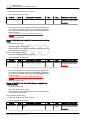
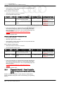
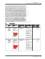
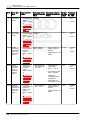
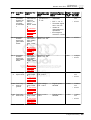
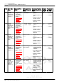
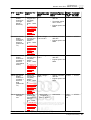
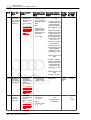
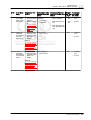
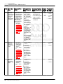
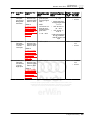
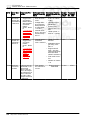
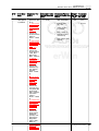
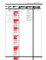
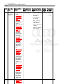
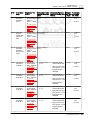
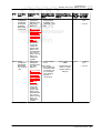
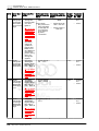
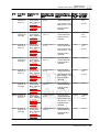
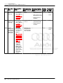
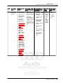
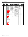
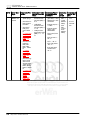
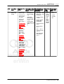
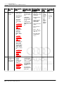
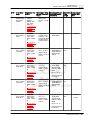
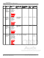
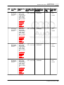
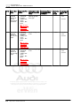
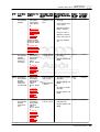
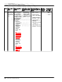
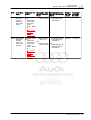
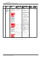
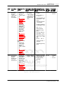
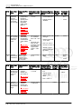
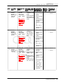
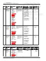
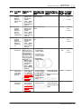
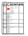
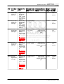
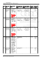
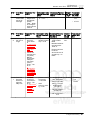
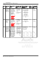
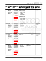
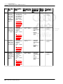
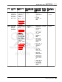
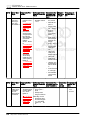
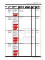
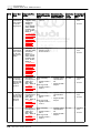
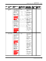
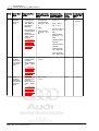
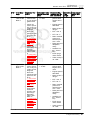
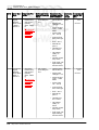
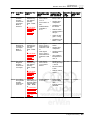
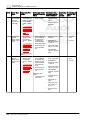
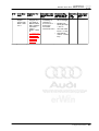
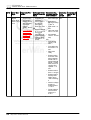
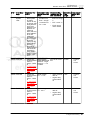
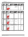
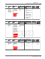
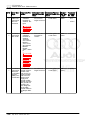
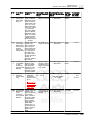
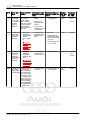
TT RS 2012 ➤ Generic Scan Tool - Edition 07.2011 DTC Error Mes‐ sage P12A Fuel Rail 2 Pressure Sensor In‐ appropri‐ ately High P12A Fuel Rail 4 Pump Con‐ trol Valve Stuck Closed P150 Comparing A engine off time from instrument cluster con‐ trol unit with engine after run time Diagnostic Pro‐ Malfunction Crite‐ Secondary Parame‐ Monitor‐ Frequency of cedure ria and Threshold ters with Enable ing Time checks, MIL Value Conditions Length Illum – Check the Fuel Pres‐ sure Sensor G247- . Re‐ fer to Check the Fuel Pressure Sensor G247- . Re‐ fer to ⇒ “3.5.5 Fuel Pressure Sensor, Checking”, page 119 .. – Check the Fuel Pres‐ sure Sensor G247- . Re‐ fer to ⇒ “3.5.5 Fuel Pressure Sensor, Checking”, page 119 . Check the ECM battery voltage inputs. The ECM must have voltage input with key off. Re‐ fer to wiring dia‐ grams for pin lo‐ cations. If key off voltage supply is present at the ECM, replace the ECM. Refer to the Repair Manual • pressure con‐ trol activity, <0.14 mPa • engine speed 600...900 RPM • AND • evap purge adap‐ tation < 20 • fuel trim activi‐ ty, >1.5 • lambda control closed loop • engine load > 10...30% • 5 Sec • Continu‐ ous • 2 DCY • Continu‐ ous • 2 DCY • once • 2 DCY • fuel cut off not ac‐ tive • pressure con‐ trol activity, <6.00 mPa • AND • fuel trim activi‐ ty, >0.9 \0...1.15 • difference be‐ • tween engineoff-time and ECM after run• time < 12 • • lambda control closed loop 5 Sec • fuel cut off not ac‐ tive Key ON during ECM after run timer - active 0 Sec. CAN active difference be‐ tween engineoff-time and ECM after runtime > 12 Sec Protected by copyright. Copying for private or commercial purposes, in part or in whole, is not permitted unless authorised by AUDI AG. AUDI AG does not guarantee or accept any liability with respect to the correctness of information in this document. Copyright by AUDI AG. 82 Rep. Gr.ST - Generic Scan Tool TT RS 2012 ➤ Generic Scan Tool - Edition 07.2011 DTC Error Mes‐ sage Diagnostic Pro‐ cedure P2004 Intake – Check the In‐ Manifold take Flap Mo‐ Runner tor -V157- / In‐ Control take Manifold Stuck Open Runner Posi‐ Bank 1 tion Sensor G336- . Refer to ⇒ “3.5.12 In‐ take Manifold Runner Posi‐ tion Sensor, Checking”, page 134 . P2008 Intake – Check the In‐ Manifold take Flap Mo‐ Runner tor -V157- / In‐ Control Cir‐ take Manifold cuit/Open Runner Posi‐ Bank 1 tion Sensor G336- . Refer to ⇒ “3.5.12 In‐ take Manifold Runner Posi‐ tion Sensor, Checking”, page 134 . P2014 Intake – Check the In‐ Manifold take Flap Mo‐ Runner Po‐ tor -V157- / In‐ sition Sen‐ take Manifold sor/Switch Runner Posi‐ Circuit Bank tion Sensor 1 G336- . Refer to ⇒ “3.5.12 In‐ take Manifold Runner Posi‐ tion Sensor, Checking”, page 134 . P2015 Intake – Check the In‐ Manifold take Flap Mo‐ Runner Po‐ tor -V157- / In‐ sition Sen‐ take Manifold sor/Switch Runner Posi‐ Circuit tion Sensor Range/Per‐ G336- . Refer formance to Bank 1 ⇒ “3.5.12 In‐ take Manifold Runner Posi‐ tion Sensor, Checking”, page 134 . Malfunction Crite‐ Secondary Pa‐ ria and Threshold rameters with Value Enable Condi‐ tions Monitor‐ Frequency of ing Time checks, MIL Il‐ Length lum signal range check --@ upper mechani‐ cal stop • normal closed position unable to reach 25 Sec • • Once • 2 DCY • Continuous • 2 DCY signal voltage < 2.62 or > 4.65 V signal range check @ lower mechani‐ cal stop • normal closed position unable to reach • signal voltage< 0.35 or > 2.38 V • signal duty cy‐ --cle > 80% • ECM power stage failure Protected by copyright. Copying for private or commercial purposes, in part or in whole, is not permitted unless authorised by AUDI AG. AUDI AG does not guarantee or accept any liability with respect to the correctness of information in this document. Copyright by AUDI AG. signal voltage < 0.2 V --- • signal duty cy‐ • cle > 80% • deviation vs. calculated val‐ • ue > 5% .2 Sec Engine speed >400 rpm • • Continuous • 2 DCY 5 Sec • • Continuous 2 DCY ECT > 10° C 3. Diagnosis and Testing 83 TT RS 2012 ➤ Generic Scan Tool - Edition 07.2011 DTC Error Mes‐ sage Diagnostic Pro‐ cedure P2017 Intake – Check the In‐ Manifold take Flap Mo‐ Runner Po‐ tor -V157- / In‐ sition Sen‐ take Manifold sor/Switch Runner Posi‐ Circuit tion Sensor Range/Per‐ G336- . Refer formance to Bank 1 ⇒ “3.5.12 In‐ take Manifold Runner Posi‐ tion Sensor, Checking”, page 134 . P2088 Camshaft – Check the Position Ac‐ Camshaft Ad‐ tuator Con‐ justment trol Circuit Valve 1 Low Bank 1 N205- . Refer to ⇒ “3.5.38 Cam‐ shaft Adjust‐ ment Valve, Checking”, page 186 . P2089 Camshaft – Check the Position Ac‐ Camshaft Ad‐ tuator Con‐ justment trol Circuit Valve 1 High Bank 1 N205- . Refer to ⇒ “3.5.38 Cam‐ shaft Adjust‐ ment Valve, Checking”, page 186 . P2090 Exhaust – Check the Camshaft Camshaft Ad‐ Position Ac‐ justment tuator Cir‐ Valve 1 (ex‐ cuit short to haust) ground N318- . Refer Bank 1 to ⇒ “3.5.39 Cam‐ shaft Adjust‐ ment Valve 1, Exhaust”, page 188 84 Rep. Gr.ST - Generic Scan Tool Malfunction Crite‐ Secondary Pa‐ ria and Threshold rameters with Value Enable Condi‐ tions Monitor‐ Frequency of ing Time checks, MIL Il‐ Length lum • .2 Sec • signal voltage > --4.8 V Signal current, • > 2.2 A • • Continuous • 2 DCY signal voltage < • Camshaft 0.5 Sec. • Continuous by copyright. Copying for private or commercial purposes, in part or in whole, is not 2.15 .. 3.25 V Protectedsolenoid permitted unless authorised by AUDI AG. AUDI not guarantee or accept any liability • AG2does DCY commanded with respect to the correctness of information in this document. Copyright by AUDI AG. OFF • • • signal voltage < • 2.15 .. 3.25 V • Engine speed, > 40 RPM Camshaft 0.5 Sec. solenoid commanded ON • Continuous • 2 DCY • Continuous • 2 DCY Engine speed > 40 RPM Camshaft 0.5 Sec solenoid commanded OFF Engine speed, > 40 RPM TT RS 2012 ➤ Generic Scan Tool - Edition 07.2011 DTC Error Mes‐ sage Diagnostic Pro‐ cedure Malfunction Crite‐ Secondary Pa‐ ria and Threshold rameters with Value Enable Condi‐ tions P2091 Exhaust – Check the • Camshaft Camshaft Ad‐ Position Ac‐ justment tuator Cir‐ Valve 1 (ex‐ cuit short to haust) Batt+ Bank N318- . Refer 1 to ⇒ “3.5.39 Cam‐ shaft Adjust‐ ment Valve 1, Exhaust”, page 188 P2096 Post Cata‐ – Check the fuel • lyst Fuel pressure. Re‐ Trim Sys‐ fer to tem Too ⇒ “3.5.2 Fuel Lean Bank Pump Pres‐ 1 sure, Check‐ ing”, page 113 signal current > • 2.2 A • Deviation • lambda control < -3% • • Monitor‐ Frequency of ing Time checks, MIL Il‐ Length lum Camshaft 0.5 Sec solenoid commanded ON • Continuous • 2 DCY Lambda con‐ 100 Sec. • trol, active 2 DCY Engine speed, > 40 RPM lambda set point 1 engine load 16….100% • Engine – Check the speed, Oxygen Sen‐ 1120-4000 sor (O2S) Be‐ RPM hind Three • Fuel cutoff Way Catalytic and catalyst Converter heating not (TWC) active G130- . Refer to • ECT > 50° C ⇒ “3.5.22 Oxy‐ gen Sensor • engine load after Catalytic changes < Converter, 7% Protected by copyright. Copying for private or commercial purposes, in part or in whole, is not Checking”, permitted unless authorised by AUDI AG. AUDI AG does not guarantee or accept any liability page 156 in this document. Copyright by AUDI• AG.O2S front, with respect to the correctness of information ready and heater active • O2S rear, ready and heater active • catalyst gas temperature 350 to 8500° C • mass flow 25 to 150 kg/h • 2nd lambda control loop active 3. Diagnosis and Testing 85 TT RS 2012 ➤ Generic Scan Tool - Edition 07.2011 DTC Error Mes‐ sage Diagnostic Pro‐ cedure Malfunction Crite‐ Secondary Pa‐ ria and Threshold rameters with Value Enable Condi‐ tions P2097 Post Cata‐ – Check the fuel • lyst Fuel pressure. Re‐ Trim Sys‐ fer to tem Too ⇒ “3.5.2 Fuel Rich Bank 1 Pump Pres‐ sure, Check‐ ing”, page 113 – Check the Oxygen Sen‐ sor (O2S) Be‐ hind Three Way Catalytic Converter (TWC) G130- . Refer to ⇒ “3.5.22 Oxy‐ gen Sensor after Catalytic Converter, Checking”, page 156 Deviation • lambda control > 3% • Error Mes‐ sage Diagnostic Pro‐ cedure Rep. Gr.ST - Generic Scan Tool 2 DCY lambda set point 1 • engine load 16….100% • Engine speed, 1120-4000 RPM • Fuel cutoff and catalyst heating not active • ECT > 50° C engine load changes < Protected by copyright. Copying for private or commercial purposes, in part or in whole, is not permitted unless authorised by7% AUDI AG. AUDI AG does not guarantee or accept any liability • O2S front, ready and heater active • O2S rear, ready and heater active • catalyst gas temperature 350 to 8500° C • mass flow 25 to 150 kg/h • 2nd lambda control loop active with respect to the correctness of information in this document. Copyright by AUDI AG. Malfunction Crite‐ Secondary Pa‐ Monitoring Frequency of ria and Threshold rameters with En‐ Time checks, MIL Value able Conditions Length Illum P2101 Throttle Ac‐ – Check the signal range check tuator Con‐ Throttle Valve • Duty cycle > trol Motor Control Mod‐ 80% Circuit ule -J338- . • ECM power Range/Per‐ Refer to stage no failure ⇒ formance “3.5.19 Throt‐ rationality check tle Valve Con‐ • deviation throt‐ trol Module, tle valve angles Checking”, vs. calculated page 149 . value > 4 .. 50 % 86 Lambda con‐ 140 Sec. • trol, active • – Check the Three Way Catalytic Con‐ verter (TWC). Refer to ⇒ “3.5.30 Cat‐ alytic Convert‐ er, Checking”, page 173 . DTC Monitor‐ Frequency of ing Time checks, MIL Il‐ Length lum --- 0.6 Sec. • Continu‐ ous • 2 DCY TT RS 2012 ➤ Generic Scan Tool - Edition 07.2011 DTC Error Mes‐ sage Diagnostic Pro‐ cedure Malfunction Crite‐ Secondary Pa‐ Monitoring Frequency of ria and Threshold rameters with En‐ Time checks, MIL Value able Conditions Length Illum P2106 Throttle Ac‐ – Check the • tuator Con‐ Throttle Valve trol System Control Mod‐ • - Forced ule -J338- . Limited Refer to Power ⇒ “3.5.19 Throt‐ tle Valve Con‐ trol Module, Checking”, page 149 . P2122 Accelerator – Check the Ac‐ • Pedal Posi‐ celerator Ped‐ tion Sensor al Position D Circuit Sensor 1 Low Input G79- / Accel‐ erator Pedal Position Sen‐ sor 2 -G185- . Refer to ⇒ “3.5.18 Ac‐ celerator Ped‐ al Position Sensor / Ac‐ celerator Ped‐ al Position Sensor 2, Checking”, page 147 . P2123 Accelerator – Check the Ac‐ • Pedal Posi‐ celerator Ped‐ tion Sensor al Position D Circuit Sensor 1 High Input G79- / Accel‐ erator Pedal Position Sen‐ sor 2 -G185- . Refer to ⇒ “3.5.18 Ac‐ celerator Ped‐ al Position Sensor / Ac‐ celerator Ped‐ al Position Sensor 2, Checking”, page 147 . P2127 Accelerator – Check the Ac‐ • Pedal Posi‐ celerator Ped‐ tion Sensor al Position E Circuit Sensor 1 Low Input G79- / Accel‐ erator Pedal Position Sen‐ sor 2 -G185- . Refer to ⇒ “3.5.18 Ac‐ celerator Ped‐ al Position Sensor / Ac‐ celerator Ped‐ al Position Sensor 2, Checking”, page 147 . duty cycle > 80 % --- 5 Sec. ECM power stage failure Signal voltage < 0.63 V Signal voltage > 4.8 V --- --- 0.2 Sec. 0.2 Sec. • Continu‐ ous • 2 DCY • Continu‐ ous • 2 DCY • Continu‐ ous • 2 DCY Protected by copyright. Copying for private or commercial purposes, in part or in whole, is not permitted unless authorised by AUDI AG. AUDI AG does not guarantee or accept any liability with respect to the correctness of information in this document. Copyright by AUDI AG. Signal voltage < 0.29 V --- 0.2 Sec. • Continu‐ ous • 2 DCY 3. Diagnosis and Testing 87 TT RS 2012 ➤ Generic Scan Tool - Edition 07.2011 DTC Error Mes‐ sage Diagnostic Pro‐ cedure Malfunction Crite‐ Secondary Pa‐ Monitoring Frequency of ria and Threshold rameters with En‐ Time checks, MIL Value able Conditions Length Illum P2128 Accelerator – Check the Ac‐ • Signal voltage --0.2 Sec. Pedal Posi‐ celerator Ped‐ > 2.5 V tion Sensor al Position E Circuit Sensor 1 High Input G79- / Accel‐ erator Pedal Position Sen‐ sor 2 -G185- . Refer to ⇒ “3.5.18 Ac‐ celerator Ped‐ al Position Sensor / Ac‐ Copying for private or commercial purposes, in part or in whole, is not Protected by copyright. permitted unlessPed‐ authorised by AUDI AG. AUDI AG does not guarantee or accept any liability celerator respect to the correctness of information in this document. Copyright by AUDI AG. alwithPosition Sensor 2, Checking”, page 147 . P2138 Accelerator – Check the Ac‐ • Signal voltage --0.24 Sec. Pedal Posi‐ celerator Ped‐ sensor 1 vs. 2 > tion Sensor al Position 0.12 to 0.70 V D / E Volt‐ Sensor 1 age Corre‐ G79- / Accel‐ lation erator Pedal Position Sen‐ sor 2 -G185- . Refer to ⇒ “3.5.18 Ac‐ celerator Ped‐ al Position Sensor / Ac‐ celerator Ped‐ al Position Sensor 2, Checking”, page 147 . P2146 Fuel Injec‐ – Check the short to battery • injection valve 0.5 Sec tor Group A Fuel injectors plus commanded Supply Volt‐ -N30, N31, • signal current < off age Circuit / N32, N33, 2.6 A • engine speed > short to N83- . Refer to short to ground 40 rpm ground ⇒ “3.5.27 Fuel Injectors, • signal current > 14.9 A Checking”, page 167 . P2149 Fuel Injec‐ – Check the short to battery • injection valve 0.5 Sec tor Group B Fuel injectors plus commanded Supply Volt‐ -N30, N31, • signal current < off age Circuit / N32, N33, 2.6 A • engine speed > Short to N83- . Refer to short to ground 40 rpm ground ⇒ “3.5.27 Fuel Injectors, • signal current > 14.9 A Checking”, page 167 . P2152 – Check the short to battery • injection valve 0.5 Sec Fuel injectors plus commanded -N30, N31, • signal current < off N32, N33, 2.6 A • engine speed > N83- . Refer to short to ground 40 rpm ⇒ “3.5.27 • signal current > Fuel Injectors, 14.9 A Checking”, page 167 . 88 Rep. Gr.ST - Generic Scan Tool • Continu‐ ous • 2 DCY • Continu‐ ous • 2 DCY • Continu‐ ous • 2 DCY • Continu‐ ous • 2 DCY • Continu‐ ous • 2 DCY TT RS 2012 ➤ Generic Scan Tool - Edition 07.2011 DTC Error Mes‐ sage Diagnostic Pro‐ cedure P2177 System Too • Lean Off Idle • Malfunction Crite‐ Secondary Pa‐ Monitoring Frequency of ria and Threshold rameters with En‐ Time checks, MIL Value able Conditions Length Illum Check O2 • sensor opera‐ tion. If any O2 codes are set, diagnose them first. Check the fuel pressure. Re‐ fer to ⇒ “3.5.2 Fuel Pump Pres‐ sure, Check‐ ing”, page 113 Adaptive value • > 28% Number of in‐ jections after engine start > 1500 • Engine speed < 860 RPM • Mass air flow < 35 kg/h • ECT > 59 °C • IAT < 85 °C • Ratio manifold pressure to ambient pres‐ sure > 0.20 • 25 Sec. • 2 DCY • 2 DCY Check for a vacuum leak Protected copyright. Copying for private or commercial purposes, in part or in whole, is not orbypoor engine permitted unless authorised acceptload any liability Deltaorpart gasket seal. by AUDI AG. AUDI AG does not• guarantee with respect to the correctness of information in this document.adaptation Copyright by AUDI AG. • Check the ready Secondary Air • Lambda con‐ Injection trol - closed Combination loop Valve. Refer to • EVAP purge ⇒ “3.5.31 Sec‐ valve closed ondary Air In‐ jection Combi‐ • Valve overlap < nation Valve, 40 °CRK Checking”, page 174 . P2178 System Too • Rich Off Idle • • Check O2 • sensor opera‐ tion. If any O2 codes are set, diagnose them first. Check the fuel pressure. Re‐ fer to ⇒ “3.5.2 Fuel Pump Pres‐ sure, Check‐ ing”, page 113 Check the Evaporative Emission (EVAP) Can‐ ister Purge Regulator Valve -N80- . Refer to ⇒ “3.5.8 EVAP Canister Purge Regu‐ lator Valve 1, Checking”, page 124 . Adaptive value • < -20% Number of in‐ jections after engine start > 1500 • Engine speed < 860 RPM • Mass air flow < 35 kg/h • ECT > 59 °C • IAT < 85 °C • Ratio manifold pressure to ambient pres‐ sure > 0.20 • Delta part load adaptation ready • Lambda con‐ trol - closed loop • EVAP purge valve closed • Valve overlap < 40 °CRK 25 Sec. 3. Diagnosis and Testing 89 TT RS 2012 ➤ Generic Scan Tool - Edition 07.2011 DTC Error Mes‐ sage P2181 Cooling System Perform‐ ance Diagnostic Pro‐ cedure Malfunction Crite‐ Secondary Pa‐ Monitoring Frequency of ria and Threshold rameters with En‐ Time checks, MIL Value able Conditions Length Illum – Check the Cooling sys‐ tem thermo‐ stat. Refer to the Repair Manual . • • – Check Engine • Coolant Tem‐ perature (ECT) Sensor -G62 or G83- . Refer to ⇒ “3.5.24 En‐ gine Coolant Temperature Sensor 1 or 2, Checking”, page 160 . P2184 Engine – Check Engine • Coolant Coolant Tem‐ Tempera‐ perature ture Sensor (ECT) Sensor 2 Circuit - G83- . Refer Low to ⇒ “3.5.24 En‐ gine Coolant Temperature Sensor 1 or 2, Checking”, page 160 . P2185 Engine – Check Engine • Coolant Coolant Tem‐ Tempera‐ perature ture Sensor (ECT) Sensor 2 Circuit -G83- . Refer High to ⇒ “3.5.24 En‐ gine Coolant Temperature Sensor 1 or 2, Checking”, page 160 . ECT too low af‐ • ter sufficient mass air flow interval = 76.5° • C • AND • mass air inte‐ gral 4.0 .. 17.0 kg • ECT at start -7 < 1000 to 60° C Sec ECT > 35° C Rep. Gr.ST - Generic Scan Tool Once • 2 DCY IAT > -7° C accum. fuel cut off < 40...220 Sec delta ambient pressure < 1.2 kPa • vehicle speed > 22 mph • vehicle speed < 75 mph • mass air flow > (33 .. 89) kg/h • mass air flow < (96 .. 220) kg/h ECT outlet > 140° C --- 2 Sec. • 2 DCY ECT outlet < -40° C --- 2 Sec. • 2 DCY Protected by copyright. Copying for private or commercial purposes, in part or in whole, is not permitted unless authorised by AUDI AG. AUDI AG does not guarantee or accept any liability with respect to the correctness of information in this document. Copyright by AUDI AG. 90 • TT RS 2012 ➤ Generic Scan Tool - Edition 07.2011 DTC Error Mes‐ sage Diagnostic Pro‐ cedure P2187 System Too • Lean at Idle Bank 1 • • Malfunction Crite‐ Secondary Pa‐ Monitoring Frequency of ria and Threshold rameters with En‐ Time checks, MIL Value able Conditions Length Illum Check for a • vacuum leak or poor engine gasket seal. Adaptive value • > 5.02% Number of in‐ jections after engine start > 1500 Check O2 sensor opera‐ tion. If any O2 codes are set, diagnose them first. • Engine speed < 860 RPM • Mass air flow < 35 kg/h Check the fuel pressure. Re‐ fer to ⇒ “3.5.2 Fuel Pump Pres‐ sure, Check‐ ing”, page 113 • ECT > 59° C • IAT < 85° C • Ratio manifold pressure to ambient pres‐ sure > 0.20 • Delta part load adaptation ready • 40 Sec. • 2 DCY 40 Sec. • 2 DCY Check the Secondary Air • Lambda con‐ Injection Protected by copyright. CopyingCombination for private or commercial purposes, in part or in whole, is trol not - closed permitted unless authorised by AUDI AG. AUDI AG does not guarantee or accept any liability loop Valve. Refer with respect to the correctness of information in this document. Copyright by AUDI AG. to • EVAP purge ⇒ “3.5.31 Sec‐ valve closed ondary Air In‐ jection Combi‐ • Valve overlap < nation Valve, 40° CRK Checking”, page 174 . P2188 System Too • Rich at Idle Bank 1 • • Check O2 • sensor opera‐ tion. If any O2 codes are set, diagnose them first. Check the fuel pressure. Re‐ fer to ⇒ “3.5.2 Fuel Pump Pres‐ sure, Check‐ ing”, page 113 Check the Evaporative Emission (EVAP) Can‐ ister Purge Regulator Valve -N80- . Refer to ⇒ “3.5.8 EVAP Canister Purge Regu‐ lator Valve 1, Checking”, page 124 . Adaptive value • < -5.02% Number of in‐ jections after engine start > 1500 • Engine speed < 860 RPM • Mass air flow < 35 kg/h • ECT > 59° C • IAT < 85° C • Ratio manifold pressure to ambient pres‐ sure > 0.20 • Delta part load adaptation ready • Lambda con‐ trol - closed loop • EVAP purge valve closed • Valve overlap < 40° CRK 3. Diagnosis and Testing 91 TT RS 2012 ➤ Generic Scan Tool - Edition 07.2011 DTC Error Mes‐ sage Diagnostic Pro‐ cedure Malfunction Crite‐ Secondary Pa‐ Monitoring Frequency of ria and Threshold rameters with En‐ Time checks, MIL Value able Conditions Length Illum P2195 O2 Sensor – Check the • trim control • Catalyst temp 200 Sec‐ Signal Heated Oxy‐ post catalyst < 350 to 850° C onds Biased/ gen Sensor 6% • engine load Stuck Lean (HO2S) changes < 7% - Bank 1, G39- . Refer Sensor 1 to • engine speed ⇒ Protected by copyright. Copying for private or commercial purposes, in part or in whole, is not 1120 ... 4000 “3.5.20unless Heat‐ permitted authorised by AUDI AG. AUDI AG does not guarantee or accept any liability RPM withOxygen respect to the correctness of information in this document. Copyright by AUDI AG. ed Sensor, • engine load Checking”, 16….100 % page 152 . • mass air flow 25 to 150 kg/h P2196 O2 Sensor – Check the • Signal Heated Oxy‐ Biased/ gen Sensor Stuck Rich (HO2S) Bank 1, G39- . Refer Sensor 1 to ⇒ “3.5.20 Heat‐ ed Oxygen Sensor, Checking”, page 152 . 92 Rep. Gr.ST - Generic Scan Tool • ECT > 50° C • lambda set point 1 • Lambda con‐ trol - active • O2 heaters ready, no DTCs • second control loop active • Fuel cutoff, cat‐ alyst heating, SAI not active trim control • post catalyst < 6% • Catalyst temp 350 to 850° C • engine speed 1120 ... 4000 RPM • engine load 16….100 % • mass air flow 25 to 150 kg/h • ECT > 50° C • lambda set point 1 • Lambda con‐ trol - active • O2 heaters ready, no DTCs • second control loop active • Fuel cutoff, cat‐ alyst heating, SAI not active engine load changes < 7% 200 Sec. • Continu‐ ous • 2 DCY • Continu‐ ous • 2 DCY TT RS 2012 ➤ Generic Scan Tool - Edition 07.2011 DTC Error Mes‐ sage Diagnostic Pro‐ cedure Malfunction Crite‐ Secondary Pa‐ Monitoring Frequency of ria and Threshold rameters with En‐ Time checks, MIL Value able Conditions Length Illum P2237 O2 Sensor – Check the • Positive Heated Oxy‐ Current gen Sensor Control Cir‐ (HO2S) cuit Open G39- . Refer • Bank 1, to Sensor 1 ⇒ • “3.5.20 Heat‐ ed Oxygen Sensor, Checking”, page 152 . P2243 O2 Sensor – Check the Reference Heated Oxy‐ Voltage Cir‐ gen Sensor cuit Open (HO2S) Bank 1, G39- . Refer Sensor 1 to ⇒ “3.5.20 Heat‐ ed Oxygen Sensor, Checking”, page 152 . P2251 O2 Sensor – Check the Negative Heated Oxy‐ Current gen Sensor Control Cir‐ (HO2S) cuit Open G39- . Refer to ⇒ “3.5.20 Heat‐ ed Oxygen Sensor, Checking”, page 152 . P2257 Secondary • Check the Air Injection Secondary Air System Injection (AIR) Control Cir‐ Pump Relay cuit Low J299- . Refer to ⇒ “3.5.33 Sec‐ ondary Air In‐ jection Pump Relay, Check‐ ing”, page 177 • • • • O2S signal front 1.49 to 1.51 V Fuel cutoff > 3 Sec. Delta lambda controller > 0.10 • O2S ceramic 30 Sec. temp > 720° C • engine start completed • Lambda con‐ trol active • Heater active • engine speed > 25 rpm • mass air inte‐ gral > 0.2 kg • Lambda modu‐ lation > 0.02 O2S signal • front > 4.70 V and Internal re‐ sistance > 950 • Ω • O2S signal front < 0.20 V And Internal re‐ • sistance > 950 Ω Heater control 10 Sec. active O2S signal front 1.47 to 1.53 V and > 950 Ω • Modeled ex‐ 30.5 Sec. haust gas temp < 750 Ω • No fuel cutoff > 2 Sec. • Heater control active Signal voltage • 0 to 3.26 V • • 2 DCY • 2 DCY • 2 DCY • 2 DCY engine start completed engine speed > 25 RPM O2S ceramic temperature > 720° C Pump relay commanded OFF 0.5 Sec. Engine speed > 80 RPM Protected by copyright. Copying for private or commercial purposes, in part or in whole, is not permitted unless authorised by AUDI AG. AUDI AG does not guarantee or accept any liability with respect to the correctness of information in this document. Copyright by AUDI AG. 3. Diagnosis and Testing 93 TT RS 2012 ➤ Generic Scan Tool - Edition 07.2011 DTC Error Mes‐ sage Diagnostic Pro‐ cedure P2258 Secondary • Air Injection System Control Cir‐ cuit High Malfunction Crite‐ Secondary Pa‐ Monitoring Frequency of ria and Threshold rameters with En‐ Time checks, MIL Value able Conditions Length Illum Check the • Secondary Air Injection (AIR) Pump Relay J299- . Refer to ⇒ “3.5.33 Sec‐ ondary Air In‐ jection Pump Relay, Check‐ ing”, page 177 Signal current . • 60 to 2.40 A P2270 O2 Sensor – Check the • Signal Oxygen Sen‐ Stuck Lean sor (O2S) Bank 1 Sen‐ G130- . Refer sor 2 to ⇒ “3.5.22 Oxy‐ gen Sensor after Catalytic • Converter, Checking”, page 156 . O2S signal rear • not oscillating at reference < • <0.649d en‐ richment after stuck lean 20% enrichment af‐ • ter stuck lean 1% • • Rep. Gr.ST - Generic Scan Tool 0.5 Sec. • 2 DCY Engine speed > 80 RPM Protected by copyright. Copying for private or commercial purposes, in part or in whole, is not permitted unless authorised by AUDI AG. AUDI AG does not guarantee or accept any liability with respect to the correctness of information in this document. Copyright by AUDI AG. For CBUA (Cali) ONLY: P2271 O2 Sensor – Check the • O2S signal rear Signal Oxygen Sen‐ not oscillating Stuck Rich sor (O2S) at reference > . Bank 1 Sen‐ G130- . Refer 0649 mV and sor 2 to enrichment af‐ ⇒ “3.5.22 Oxy‐ ter stuck rich gen Sensor 15% after Catalytic • enrichment af‐ Converter, ter stuck rich Checking”, 1% page 156 . response time check • response time > 2.5 Sec 94 Pump relay commanded ON Mass air flow > 100c. 30 kg/h • Continu‐ ous Modeled ex‐ haust gas temp > 700° C • 2 DCY O2S rear read‐ iness > 10 Sec. 2nd lambda control - closed loop • Mass air flow 100 Sec. 22 to 120 kg/h • Continu‐ ous • Modeled ex‐ haust gas temp > 300 °C • 2 DCY • O2S rear read‐ iness > 10 Sec. • 2nd lambda control - closed loop • mass air flow > 10 kg/h • O2S rear no DTC • O2S rear sen‐ sor voltage > 0,57 V • fuel cut off ac‐ tive TT RS 2012 ➤ Generic Scan Tool - Edition 07.2011 DTC Error Mes‐ sage Diagnostic Pro‐ cedure P2274 O2 Sensor • Signal Stuck Lean Bank 1 Sen‐ sor 3 Malfunction Crite‐ Secondary Pa‐ Monitoring Frequency of ria and Threshold rameters with En‐ Time checks, MIL Value able Conditions Length Illum Check the • Oxygen Sen‐ sor (O2S) 2 Behind Three Way Catalytic Converter (TWC) G465- . Refer to ⇒ “3.5.22 Oxy‐ gen Sensor after Catalytic Converter, Checking”, page 156 O2S rear not • oscillating at reference < 0.64 to 0.65 V • and enrich‐ ment after stuck lean 20% • • Mass air flow 100 Sec. 22 to 120 kg/h • 2 DCY Modeled ex‐ haust gas temp > 300 °C O2S rear read‐ iness > 10 Sec. 2nd lambda control - closed loop Protected by copyright. Copying for private or commercial purposes, in part or in whole, is not permitted unless authorised by AUDI AG. AUDI AG does not guarantee or accept any liability with respect to the correctness of information in this document. Copyright by AUDI AG. 3. Diagnosis and Testing 95 TT RS 2012 ➤ Generic Scan Tool - Edition 07.2011 DTC Error Mes‐ sage Diagnostic Pro‐ cedure P2275 O2 Sensor • Signal Stuck Rich Bank 1 Sen‐ sor 3 Malfunction Crite‐ Secondary Pa‐ Monitoring Frequency of ria and Threshold rameters with En‐ Time checks, MIL Value able Conditions Length Illum Check the • O2S rear not Oxygen Sen‐ oscillating at sor (O2S) 2 reference > Behind Three 0.64 to 0.65 V Way Catalytic and enrich‐ Converter ment after (TWC) stuck rich 15% G465- . Refer OR to ⇒ “3.5.22 Oxy‐ • Sensor voltage of >= 0.15 V af‐ gen Sensor ter oxygen after Catalytic mass flow (af‐ Converter, ter fuel cutoff) > Checking”, 1500 to 3000 page 156 mg with >= 1 check • Mass air flow 10 to 215 22 to 120 kg/h Sec. • Modeled ex‐ haust gas temp > 300 °C • Fuel cutoff > 3 Sec. • O2S rear read‐ iness > 10 Sec. • 2nd lambda control - closed loop OR Protected by copyright. Copying for private or commercial purposes, in part whole,of is not • or inTime fuel permitted unless authorised by AUDI AG. AUDI AG does not guarantee or accept any liability cutoff <= 90 with respect to the correctness of information in this document. Copyright by AUDI AG. Sec. 96 Rep. Gr.ST - Generic Scan Tool • Time after last fuel cutoff >= 5 Sec. • Rear O2S ready • Exhaust temp at sensor devi‐ ation between actual and ex‐ pected lambda signal < 8 after time since fuel cutoff at first cylinder >= 2 Sec. • Exhaust mass flow >= 12 kg/h • Exhaust mass flow dynamic within range -500 to 500 kg/ h • Sensor voltage at start of measurement > 0.45 V • Target voltage end of meas‐ urement <= 0.15 V • 2 DCY TT RS 2012 ➤ Generic Scan Tool - Edition 07.2011 DTC Error Mes‐ sage P2279 Intake Air System Leak Diagnostic Pro‐ cedure • Malfunction Crite‐ Secondary Pa‐ Monitoring Frequency of ria and Threshold rameters with En‐ Time checks, MIL Value able Conditions Length Illum Check the in‐ • take system for leaks. Check oil cap for proper seal • along with en‐ gine cover gaskets or oil dipstick not seated in tube, that may allow addition‐ al air into crankcase. The PCV sys‐ tem is not me‐ tered (no valve) so any additional air entering through an engine gasket will cause an increase in PCV volume drawn into the intake mani‐ fold. Offset value throttle mass flow > 19 kg/h correction fac‐ • tor > 0.95 • Protected by copyright. Copying for private or commercial purposes, in part or in whole, is not permittedP2293 unless authorised AUDI AG.–AUDI AG doesthe not guarantee or accept anybe‐ liability Fuel by Rail Check difference with respect to the correctness of information in thisPressure document. Copyright by AUDI Fuel tween MPaAG.actual P2294 Fuel Rail P2295 Fuel Rail Sensor G247- . Refer to ⇒ “3.5.5 Fuel Pressure Sen‐ sor, Check‐ ing”, page 119 .. – Check the Fuel Pressure Sensor G247- . Refer to ⇒ “3.5.5 Fuel Pressure Sen‐ sor, Check‐ ing”, page 119 .. – Check the Fuel Pressure Sensor G247- . Refer to ⇒ “3.5.5 Fuel Pressure Sen‐ sor, Check‐ ing”, page 119 .. • pressure - target pressure = > 1.3 <-3 MPa signal voltage 2.3 ... 2.7 V signal voltage 1.8 .. 2.2 V Desired mass 2 Sec. flow 5 to 21 kg/ h • 2 DCY • Continu‐ ous • 2 DCY ECT >-42.8° C EVAP purge valve closed fuel cut off not ac‐ 3.5 Sec tive • valve comman‐ 1 Sec ded off • Continu‐ ous • engine relay commanded on • 2 DCY • valve comman‐ 1 Sec ded off • Continu‐ ous • engine relay commanded on • 2 DCY 3. Diagnosis and Testing 97 TT RS 2012 ➤ Generic Scan Tool - Edition 07.2011 DTC Error Mes‐ sage P2296 Fuel Rail DTC Error Mes‐ sage Diagnostic Pro‐ cedure Malfunction Crite‐ Secondary Pa‐ Monitoring Frequency of ria and Threshold rameters with En‐ Time checks, MIL Value able Conditions Length Illum – Check the signal voltage > Fuel Pressure 3.9 V Sensor G247- . Refer to ⇒ “3.5.5 Fuel Pressure Sen‐ sor, Check‐ ing”, page 119 .. • valve comman‐ 1 Sec ded on • Continu‐ ous • engine relay commanded on • 2 DCY Diagnostic Pro‐ Malfunction Crite‐ Secondary Param‐ Monitoring Frequency of cedure ria and Threshold eters with Enable Time checks, MIL Value Conditions Length Illum P2300 Ignition Coil – Check the Ig‐ • short to ground • Engine speed, > 0.5 V A Primary nition Coils signal voltage < 1500 RPM Control Cir‐ with Power 0.5 .. 1.0 V cuit Low Output Stage . Refer to ⇒ “3.5.41 Ig‐ nition Coil with Power Output Stage, Checking”, page 192 . P2301 Ignition Coil – Check the Ig‐ • Signal voltage • Engine speed > 0.5 Sec. A Primary nition Coils > 5.2 .. 6.0 V 1500 RPM Control Cir‐ with Power cuit High Output Stage . Refer to ⇒ “3.5.41 Ig‐ nition Coil with Power Output Stage, Checking”, page 192 . P2303 Ignition Coil – Check the Ig‐ • short to ground • Engine speed, > 0.5 Sec. Protected by Coils copyright. Copying for private or commercial part or in whole, is not B Primary nition signal voltage < purposes, 1500 inRPM permitted unless authorised by AUDI AG. AUDI AG does not guarantee or accept any liability Control Cir‐ with Power 0.5 .. 1.0 V with respect to the correctness of information in this document. Copyright by AUDI AG. cuit Low Output Stage . Refer to ⇒ “3.5.41 Ig‐ nition Coil with Power Output Stage, Checking”, page 192 . 98 Rep. Gr.ST - Generic Scan Tool • Continu‐ ous • 2 DCY • Continu‐ ous • 2 DCY • Continu‐ ous • 2 DCY TT RS 2012 ➤ Generic Scan Tool - Edition 07.2011 DTC Error Mes‐ sage Diagnostic Pro‐ Malfunction Crite‐ Secondary Param‐ Monitoring Frequency of cedure ria and Threshold eters with Enable Time checks, MIL Value Conditions Length Illum P2304 Ignition Coil – Check the Ig‐ • Signal voltage B Primary nition Coils > 5.2 .. 6.0 V Control Cir‐ with Power cuit High Output Stage . Refer to ⇒ “3.5.41 Ig‐ nition Coil with Power Output Stage, Checking”, page 192 . P2306 Ignition Coil – Check the Ig‐ • Signal current C Primary nition Coils > 24 mA Control Cir‐ with Power cuit Low Output Stage . Refer to ⇒ “3.5.41 Ig‐ nition Coil with Power Output Stage, Checking”, page 192 . P2307 Ignition Coil – Check the Ig‐ • Signal voltage C Primary nition Coils > 5.2 .. 6.0 V Protected by copyright. Copying for private or commercial purposes, in part or in whole, is not Control Cir‐ with Power permitted unless authorised by AUDI AG. AUDI AG does not guarantee or accept any liability Highof informationOutput with respect to the cuit correctness in this document. Copyright by AUDI AG. Stage . Refer to ⇒ “3.5.41 Ig‐ nition Coil with Power Output Stage, Checking”, page 192 . P2309 Ignition Coil – Check the Ig‐ • Signal current D Primary nition Coils > 24 mA Control Cir‐ with Power cuit Low Output Stage . Refer to ⇒ “3.5.41 Ig‐ nition Coil with Power Output Stage, Checking”, page 192 . • • • • Engine speed > 1500 RPM 0.5 Sec. short to ground signal voltage < 0.5 .. 1.0 V 0.5 Sec. Engine speed > 1500 RPM 0.5 Sec. Engine speed, > 1500 RPM 0.5 Sec. • Continu‐ ous • 2 DCY • Continu‐ ous • 2 DCY • Continu‐ ous • 2 DCY • Continu‐ ous • 2 DCY 3. Diagnosis and Testing 99 TT RS 2012 ➤ Generic Scan Tool - Edition 07.2011 DTC Error Mes‐ sage Diagnostic Pro‐ Malfunction Crite‐ Secondary Param‐ Monitoring Frequency of cedure ria and Threshold eters with Enable Time checks, MIL Value Conditions Length Illum P2310 Ignition Coil – Check the Ig‐ • D Primary nition Coils Control Cir‐ with Power cuit High Output Stage . Refer to ⇒ “3.5.41 Ig‐ nition Coil with Power Output Stage, Checking”, page 192 . P2312 Ignition Coil – Check the Ig‐ • “E” Primary nition Coils Control Cir‐ with Power cuit Low Output Stage . Refer to ⇒ “3.5.41 Ig‐ nition Coil with Power Output Stage, Checking”, page 192 . P2313 Ignition Coil – Check the Ig‐ • “E” Primary nition Coils Control Cir‐ with Power cuit High Output Stage . Refer to ⇒ “3.5.41 Ig‐ nition Coil with Power Output Stage, Checking”, page 192 . DTC Error Mes‐ sage Signal current > 24 mA • Signal voltage • > 5.2 .. 6.0 V Engine speed > 1500 RPM Engine speed, > 1500 RPM Engine speed > 1500 RPM 0.5 Sec. 0.5 Sec. 0.5 Sec. • Continu‐ ous • 2 DCY • Continu‐ ous • 2 DCY • Continu‐ ous • 2 DCY Diagnostic Pro‐ Malfunction Crite‐ Secondary Parame‐ Monitor‐ Frequency cedure ria and Threshold ters with Enable Con‐ ing Time of checks, Value ditions Length MIL Illum P240 Evaporative – Check the • A Emission Leak Detec‐ System tion Pump Leak Detec‐ (LDP) tion Pump V144- . Refer Heater to Control Cir‐ ⇒ cuit Open “3.5.13 Leak Detection Pump, Checking ”, page 136 100 Signal voltage • > 5.2 .. 6.0 V Rep. Gr.ST - Generic Scan Tool Signal voltage • > 4.7 to 5.4 V EVAP pump elec‐ 0.5 Sec. tric drive comman‐ ded off • 2 DCY Protected by copyright. Copying for private or commercial purposes, in part or in whole, is not permitted unless authorised by AUDI AG. AUDI AG does not guarantee or accept any liability with respect to the correctness of information in this document. Copyright by AUDI AG. TT RS 2012 ➤ Generic Scan Tool - Edition 07.2011 DTC Error Mes‐ sage Diagnostic Pro‐ Malfunction Crite‐ Secondary Parame‐ Monitor‐ Frequency cedure ria and Threshold ters with Enable Con‐ ing Time of checks, Value ditions Length MIL Illum P240 Evaporative – Check the • Signal voltage • EVAP pump elec‐ 0.5 Sec. • 2 DCY B Emission Leak Detec‐ < 2.74 to 3.26 V tric drive comman‐ System tion Pump ded off Leak Detec‐ (LDP) tion Pump V144- . Refer Heater to Control Cir‐ ⇒ cuit Low “3.5.13 Leak Detection Pump, Checking ”, page 136 P240 Evaporative – Check the • Signal current • EVAP pump elec‐ 0.5 Sec. • 2 DCY C Emission Leak Detec‐ > 2.2 to 4 A tric drive comman‐ System tion Pump ded on Leak Detec‐ (LDP) tion Pump V144- . Refer Heater to Control Cir‐ ⇒ cuit High “3.5.13 Leak Detection Pump, Checking ”, page 136 P2400 Evaporative – Check the • Signal voltage • LDP commanded 0.5 Sec. • Continu‐ Emission Leak Detec‐ > 4.40 to 5.60 V OFF ous System tion Pump • engine speed >40 • 2 DCY Leak Detec‐ (LDP) RPM tion Pump V144- . Refer Control Cir‐ to cuit/Open ⇒ “3.5.13 Leak Detection Pump, Checking ”, page 136 P2401 Evaporative For Model Year • Signal voltage • LDP commanded 0.5 Sec. • Continu‐ Emission 2011 > < 2.74 to 3.26 V OFF ous System – Check the • engine speed >40 • 2 DCY Leak Detec‐ Leak Detec‐ RPM tion Pump tion Pump Control Cir‐ (LDP) cuit Low V144- . Refer to ⇒ “3.5.13 Leak Detection Pump, Checking ”, page 136 P2402 Evaporative For Model Year • signal current > • LDP commanded 0.5 Sec. • Continu‐ Emission 2011 > 3A ON ous System – Check the • engine speed >40 • 2 DCY Leak Detec‐ Leak Detec‐ RPM tion Pump tion Pump Control Cir‐ (LDP) cuit High V144- . Refer Protected by copyright. Copying for private or commercial purposes, in part or in whole, is not to permitted unless authorised by AUDI AG. AUDI AG does not guarantee or accept any liability with respect to the correctness of information in this document. Copyright by AUDI AG. ⇒ “3.5.13 Leak Detection Pump, Checking ”, page 136 3. Diagnosis and Testing 101 TT RS 2012 ➤ Generic Scan Tool - Edition 07.2011 DTC Error Mes‐ sage Diagnostic Pro‐ Malfunction Crite‐ Secondary Parame‐ Monitor‐ Frequency cedure ria and Threshold ters with Enable Con‐ ing Time of checks, Value ditions Length MIL Illum P2403 Evaporative – Check the • Emission Leak Detec‐ System tion Pump Leak Detec‐ (LDP) tion Pump V144- . Refer Sense Cir‐ to cuit/Open ⇒ “3.5.13 Leak Detection Pump, Checking ”, page 136 . Low signal volt‐ • age >1 Sec. LDP commanded 10 Sec. OFF • Once/ DCY • evap purge valve closed • 2 DCY • ECT at start >= 4...35° C • LDP activated, Se‐ lected gear = any drive • ambient pressure > 743,5 hPa • number of diagno‐ sis attempts <=15 • IAT > 4° C Protected by copyright. Copying for •private or commercial purposes, in part or in whole, is not delta ambient permitted unless authorised by AUDI AG. AUDI AG does not guarantee or accept any liability pressure < 300 with respect to the correctness of information in this document. Copyright by AUDI AG. [Pa] 102 Rep. Gr.ST - Generic Scan Tool • IAT drop after en‐ gine start, < 7°K • Time after engine start > 175 - 1200 Sec. • ECT 4 .. 115° C • Vehicle speed >= 19 mph • selected gear any drive TT RS 2012 ➤ Generic Scan Tool - Edition 07.2011 DTC Error Mes‐ sage Diagnostic Pro‐ Malfunction Crite‐ Secondary Parame‐ Monitor‐ Frequency cedure ria and Threshold ters with Enable Con‐ ing Time of checks, Value ditions Length MIL Illum P2404 Evaporative – Check the • Emission Leak Detec‐ System tion Pump Leak Detec‐ (LDP) tion Pump V144- . Refer Sense to Range/Per‐ ⇒ formance “3.5.13 Leak Detection Pump, Checking ”, page 136 . High signal • voltage > 0.36 Sec. • LDP commanded 10 Sec. ON • Once/ DCY evap purge valve closed • 2 DCY • ECT at start >= 4...35° C • LDP activated, Se‐ lected gear = any drive • ambient pressure > 743,5 hPa • number of diagno‐ sis attempts <=15 • IAT > 4° C • delta ambient pressure < 300 [Pa] • IAT drop after en‐ gine start, < 7°K • Time after engine start > 175 - 1200 Protected by copyright. Copying for private or commercial purposes, in part or in whole, is not Sec. permitted unless authorised by AUDI AG. AUDI AG does not guarantee or accept any liability • ECT 4 .. 115° C • Vehicle speed >= 19 mph • selected gear any drive with respect to the correctness of information in this document. Copyright by AUDI AG. 3. Diagnosis and Testing 103 TT RS 2012 ➤ Generic Scan Tool - Edition 07.2011 DTC Error Mes‐ sage Diagnostic Pro‐ Malfunction Crite‐ Secondary Parame‐ Monitor‐ Frequency cedure ria and Threshold ters with Enable Con‐ ing Time of checks, Value ditions Length MIL Illum P2407 Evaporative – Check the • Fluctuation of • ECT > 60 °C 21.5 Sec. • 2 DCY Emission Leak Detec‐ EVAP pump System tion Pump current during • ECT at start < 60 ° C Leak Detec‐ (LDP) reference tion Pump V144- . Refer measurement • AAT > 4 and < 35 ° Sense Cir‐ to > 1 mA C cuit Inter‐ ⇒ mittent/Er‐ “3.5.13 Leak • Drop of EVAP • Altitude <= 2700 m pump current ratic Detection during pump Timeorsince engine Protected by copyright. Copying•for private commercial purposes, in part or in whole, is not Pump, phase 6 mA by AUDIstart unless>authorised AG. AUDI does not guarantee or accept any liability >= AG 600 Sec. Checking ”, permitted withfor respect correctness of information in this document. Copyright by AUDI AG. >= to3the Sec. page 136 . • Integrated EVAP purge flow since last purge stop > 2 g P2414 O2 Sensor – Check the • Exhaust Heated Oxy‐ Sample Er‐ gen Sensor ror Bank 1, (HO2S) Sensor 1 G39- . Refer to ⇒ “3.5.20 Heat‐ ed Oxygen Sensor, Checking”, page 152 . 104 Rep. Gr.ST - Generic Scan Tool • Integrated EVAP purge flow since last monitoring run >0g • Intake manifold vacuum > 100 hPa • Vehicle speed < 120 km/h • Fuel volume flow <= 5 ml/s • Change in battery voltage during monitoring < 1.50 V • Engine speed not at idle and above 20 RPM • O2S front ready Signal Voltage • 2.5 to 3.06 V desired Lambda value < 1.6 • Fuel cut off, Not active • Heater control closed loop • engine speed > 25 rpm • O2S no DTC • O2S ceramic temp, >715° C • low fuel signal on than wait > 600 [s] 10 Sec. • 2 DCY TT RS 2012 ➤ Generic Scan Tool - Edition 07.2011 DTC Error Mes‐ sage Diagnostic Pro‐ Malfunction Crite‐ Secondary Parame‐ Monitor‐ Frequency cedure ria and Threshold ters with Enable Con‐ ing Time of checks, Value ditions Length MIL Illum P2431 Secondary – Check the • Difference be‐ • Secondary Air In‐ 0.5 Sec. Air Injection Secondary tween SAI jection - done System Air Air Injection pressure and Flow Pres‐ Sensor 1 ambient pres‐ sure Sensor G609- . Re‐ sure NOT -60 Circuit fer to to 60 hPa Range/Per‐ ⇒ formance “3.5.35 Sec‐ ondary Air In‐ jection Sen‐ sor 1, Check‐ ing”, page 180 . P2432 Secondary – Check the • Signal voltage --0.5 Sec. Air Injection Secondary < 0.5 V System Air Air Injection Flow/Pres‐ Sensor 1 sure Sensor G609- . Re‐ Circuit Low fer to ⇒ “3.5.35 Sec‐ ondary Air In‐ jection Sen‐ sor 1, Check‐ ing”, page 180 . P2433 Secondary – Check the • Signal voltage --0.5 Sec. Air Injection Secondary > 4.5 V System Air Air Injection Flow/Pres‐ Sensor 1 sure Sensor G609- . Re‐ Circuit High fer to ⇒ “3.5.35 Sec‐ ondary Air In‐ jection Sen‐ sor 1, Check‐ ing”, page 180 . P2440 Secondary – Check the • SAI pressure • ECT 3 to 105 °C 55.5 Sec. Air Injection Combination sensor meas‐ System Valve . Refer ured with SAI • IAT 4.5 to 143.3 °C Switching to pressure vs. • Altitude < 2700 m Valve Stuck ⇒ modeled while Open “3.5.31 Sec‐ SAI valve • SAI pressure sen‐ closed < 64.8% ondary Air In‐ sor - ready jection Com‐ bination Valve, Checking”, page 174 . Protected by copyright. Copying for private or commercial purposes, in part or in whole, is not • Once/ DCY • 2 DCY • 2 DCY • 2 DCY • Once/ DCY • 2 DCY permitted unless authorised by AUDI AG. AUDI AG does not guarantee or accept any liability – Check the to the correctness of information in this document. Copyright by AUDI AG. with respect Secondary Air Injection Sensor 1 G609- . Re‐ fer to ⇒ “3.5.35 Sec‐ ondary Air In‐ jection Sen‐ sor 1, Check‐ ing”, page 180 . 3. Diagnosis and Testing 105 TT RS 2012 ➤ Generic Scan Tool - Edition 07.2011 DTC Error Mes‐ sage Diagnostic Pro‐ Malfunction Crite‐ Secondary Parame‐ Monitor‐ Frequency cedure ria and Threshold ters with Enable Con‐ ing Time of checks, Value ditions Length MIL Illum P2450 Evaporative – Check the • Emission Leak Detec‐ System tion Pump Switching (LDP) Valve Per‐ V144- . Refer formance/ to Stuck Open ⇒ “3.5.13 Leak Detection Pump, Checking ”, page 136 EVAP pump current differ‐ ence between reference measurement to idle < 3 mA • ECT > 60 °C • ECT at start < 60 ° C • AAT > 4 and < 35 ° C • Altitude <= 2700 m • Time since engine start >= 600 Sec. • Integrated EVAP purge flow since 21.5 Sec. • 2 DCY Protected by copyright. Copying for private or commercial purposes, in part or in whole, is not last purge stop 2 AG does not guarantee or accept any liability permitted unless authorised by AUDI AG.> AUDI g correctness of information in this document. Copyright by AUDI AG. with respect to the P2539 Fuel Sys‐ tem P2541 Fuel Sys‐ tem 106 – Check the • Fuel Pres‐ sure Sensor G247- . Re‐ fer to ⇒ “3.5.5 Fuel Pressure Sensor, Checking”, page 119 . – Check the • Fuel Pres‐ sure Sensor G247- . Re‐ fer to ⇒ “3.5.5 Fuel Pressure Sensor, Checking”, page 119 . Rep. Gr.ST - Generic Scan Tool • Integrated EVAP purge flow since last monitoring run >0g • Intake manifold vacuum > 100 hPa • Vehicle speed < 120 km/h • Fuel volume flow <= 5 ml/s • Change in battery voltage during monitoring < 1.50 V • Engine speed not at idle and above 20 RPM • O2S front ready "signal range --check out of range high" sig‐ nal voltage "> 4.9 >4,8" V 1 Sec "signal range --check out of range low" sig‐ nal voltage "< 0.2 <0,2" V 1 Sec • Continu‐ ous • 2 DCY • Continu‐ ous • 2 DCY TT RS 2012 ➤ Generic Scan Tool - Edition 07.2011 DTC Error Mes‐ sage Diagnostic Pro‐ Malfunction Crite‐ Secondary Parame‐ Monitor‐ Frequency cedure ria and Threshold ters with Enable Con‐ ing Time of checks, Value ditions Length MIL Illum P2626 O2 Sensor – Check the • Pumping Oxygen Sen‐ Current sor (O2S) Trim Circuit G39- . Refer Open Bank to 1 Sensor 1 ⇒ “3.5.20 Heat‐ ed Oxygen Sensor, Checking”, page 152 . DTC Error Mes‐ sage P3081 Engine Tempera‐ ture Too Low O2S signal front > 3.1 V (lean) • engine start com‐ 4 Sec. pleted • engine speed > 25 rpm • O2S ceramic temp > 720° C • Modeled exhaust temp, < 750° C • Fuel cut off, Active • Heater control closed loop • 2 DCY Diagnostic Pro‐ Malfunction Crite‐ Secondary Parame‐ Monitoring Frequency cedure ria and Threshold ters with Enable Con‐ Time Length of checks, Value ditions MIL Illum – Check the • coolant ther‐ mostat. Re‐ fer to the Re‐ pair Manual Difference be‐ tween ECT and modeled ECT > 10 K ECT < 48° C 2 Sec. • Once • 2 DCY – Check the Engine Cool‐ ant Temper‐ ature (ECT) Sensor -G62 or G83- . Re‐ fer to ⇒ “3.5.24 En‐ gine Coolant Temperature Sensor 1 or 2, Checking”, page 160 . DTC Error Mes‐ sage Diagnostic Pro‐ Malfunction Crite‐ Secondary Parame‐ Monitor‐ Frequency cedure ria and Threshold ters with Enable Con‐ ing Time of checks, ProtectedValue by copyright. Copying for private or commercial purposes, in partLength or in whole, is not ditions MIL Illum permitted unless authorised by AUDI AG. AUDI AG does not guarantee or accept any liability to the correctness of information in this document. by AUDI AG. • U000 High Speed – Check thewith respect • CAN message Time after ignitionCopyright on 250 1 CAN Com‐ CAN-Bus = no feedback = 500 mSec. mSec. munication terminal re‐ • Bus sistance. Re‐ fer to ⇒ “3.5.43 CAN Bus Terminal Resistance, Checking”, page 195 . Continu‐ ous 2 DCY 3. Diagnosis and Testing 107 TT RS 2012 ➤ Generic Scan Tool - Edition 07.2011 DTC Error Mes‐ sage Diagnostic Pro‐ Malfunction Crite‐ Secondary Parame‐ Monitor‐ Frequency cedure ria and Threshold ters with Enable Con‐ ing Time of checks, Value ditions Length MIL Illum U000 High Speed – Check the • 2 CAN Com‐ CAN-Bus munication terminal re‐ Bus Per‐ sistance. Re‐ formance fer to ⇒ “3.5.43 CAN Bus Terminal Resistance, Checking”, page 195 . U010 Lost Com‐ – Check the • 1 munication CAN-Bus with TCM terminal re‐ sistance, Transmis‐ sion Control Module J217- to En‐ gine Control Module (ECM) J623- . Refer to ⇒ “3.5.44 CANBus Terminal Resistance, Transmis‐ sion Control Module to Engine Con‐ trol Module, Checking”, page 197 . U012 Lost Com‐ Check for ABS • 1 munication module commu‐ With Anti- nication with Lock Brake scan tool. If no System communication (ABS) Con‐ with scan tool, trol Module check power supply and ground to ABS module. If power and ground are present, per‐ form diagnosis on the ABS module. Refer to the Repair Man‐ ual. 108 Rep. Gr.ST - Generic Scan Tool Global time Time after ignition on 500 out, no mes‐ = 500 mSec. mSec. sages received • Continu‐ ous • 2 DCY Time out, no message re‐ ceived • 2 DCY Time after ignition on 5000 = 500 mSec. mSec. Protected by copyright. Copying for private or commercial purposes, in part or in whole, is not permitted unless authorised by AUDI AG. AUDI AG does not guarantee or accept any liability with respect to the correctness of information in this document. Copyright by AUDI AG. No CAN mes‐ Time after ignition on 500 sages received = 500 mSec. mSec. • 2 DCY TT RS 2012 ➤ Generic Scan Tool - Edition 07.2011 DTC Error Mes‐ sage Diagnostic Pro‐ Malfunction Crite‐ Secondary Parame‐ Monitor‐ Frequency cedure ria and Threshold ters with Enable Con‐ ing Time of checks, Value ditions Length MIL Illum U014 Lost Com‐ Check for Data • No CAN mes‐ Time after ignition on 500 • 2 DCY 6 munication Bus On Board sages received = 500 mSec. mSec. With Gate‐ Diagnostic Inter‐ way "A" face communi‐ cation with scan tool. If no com‐ munication with scan tool, check power and ground to Data Bus On Board Diagnostic Inter‐ face. If no other communication faults are set, the ECM may be at fault. U015 Lost Com‐ Check TSB's for • No CAN mes‐ Time after ignition on 2000 • 2 DCY 5 munication software up‐ sages received = 500 mSec. mSec. With Instru‐ date. Check for ment Panel IPC communi‐ Cluster cation with scan (IPC) Con‐ tool. If IPC has trol Module no communica‐ tion with scan tool check pow‐ er and ground to cluster. If present, replace the cluster U030 Software In‐ Check ECM cal‐ • Manual trans‐ Time after ignition on 100 • 2 DCY 2 compatibili‐ ibration. Fault mission coded = 500 mSec. mSec. ty with will set if ECM ECM and mes‐ Transmis‐ was program‐ sages received sion Control med for a man‐ from TCM Module ual trans in an automatic trans‐ mission vehicle. U032 CAN: In‐ – Check the receiving fault val‐ • CAN active 6 Sec • Continu‐ 3 strument CAN-Bus ue = -50° C ous • time after ignition cluster Audi terminal re‐ on >2 Sec • 2 DCY only sistance. Re‐ fer to ⇒ “3.5.43 CAN Bus Terminal Resistance, Checking”, page 195 . U040 Invalid Data Check TSB's for • Implausible da‐ Time after ignition on 60 mSec. • 2 DCY copyright. Copyingre‐ for private or=commercial purposes, in part or in whole, is not 2 Received software up‐Protected by ta message 500 mSec. unless authorised by AUDI AG. AUDI AG does not guarantee or accept any liability From date. Check permitted for ceived Transmis‐ correct soft‐ with respect to the correctness of information in this document. Copyright by AUDI AG. sion Control ware. Check to Module see if any other modules have set an invalid data code from TCM (ABS, Cluster etc.). If so and the soft‐ ware is correct, replace the TCM. 3. Diagnosis and Testing 109 TT RS 2012 ➤ Generic Scan Tool - Edition 07.2011 DTC Error Mes‐ sage U041 Invalid Data 5 Received From AntiLock Brake System Control Module Diagnostic Pro‐ Malfunction Crite‐ Secondary Parame‐ Monitor‐ Frequency cedure ria and Threshold ters with Enable Con‐ ing Time of checks, Value ditions Length MIL Illum Check ABS for • any sensor faults. Check • ABS module with scan tool for correct calibra‐ tion software, • veh info and cor‐ rect VIN. U042 Invalid Data – Check the • 2 Received Ambient Air From Body Temperature Control Sensor Module G17- . Refer to ⇒ “3.5.25 Am‐ bient Air Temperature Sensor, Checking”, page 164 . U042 Invalid Data – Check the • 3 Received CAN-Bus From In‐ terminal re‐ strument sistance. Re‐ Panel Con‐ fer to trol (IPC) ⇒ Module “3.5.43 CAN Bus Terminal Resistance, Checking”, page 195 . U044 Invalid Data Check TSB's for • 7 Received software up‐ From Gate‐ date. Check oth‐ way Module er modules on bus for similar message. If only 1 module has this DTC set, that module may not be reading the information and require re‐ placement. Sensor signal failure Time after ignition on 500 = 500 mSec. mSec. • Continu‐ ous • 2 DCY 3 Sec. • 2 DCY 2 Sec. • Continu‐ ous • 2 DCY • 2 DCY None, or im‐ plausible infor‐ mation CAN 1 VSS signal incorrect > 206 MPH Ambient tem‐ • perature value initialization = • 00h • Temperature received from CAN = 49.5° C Key ON Status ambient temperature from instrument cluster - no fault Ambient temp sen‐ sor - no fault CAN active CAN message Time after ignition on 300 incorrect = 500 mSec. mSec. Protected by copyright. Copying for private or commercial purposes, in part or in whole, is not permitted unless authorised by AUDI AG. AUDI AG does not guarantee or accept any liability with respect to the correctness of information in this document. Copyright by AUDI AG. 110 Rep. Gr.ST - Generic Scan Tool TT RS 2012 ➤ Generic Scan Tool - Edition 07.2011 3.5 Diagnostic Procedures ⇒ “3.5.1 Fuel Pump Voltage Supply, Checking”, page 112 ⇒ “3.5.2 Fuel Pump Pressure, Checking”, page 113 ⇒ “3.5.3 Fuel Pump Delivery Rate, Checking”, page 115 ⇒ “3.5.4 Fuel Pump Electrical, Testing”, page 116 ⇒ “3.5.5 Fuel Pressure Sensor, Checking”, page 119 ⇒ “3.5.6 Fuel Metering Valve, Checking”, page 120 ⇒ “3.5.7 EVAP System, Checking for Leaks”, page 123 ⇒ “3.5.8 EVAP Canister Purge Regulator Valve 1, Checking”, page 124 ⇒ “3.5.9 Exhaust Flap Valve 1, Checking”, page 126 ⇒ “3.5.10 Exhaust Gas Temperature Sensor 1, Checking”, page 128 ⇒ “3.5.11 Intake Air Temperature Sensor and Manifold Absolute Pressure Sensor, Checking”, page 130 ⇒ “3.5.12 Intake Manifold Runner Position Sensor, Checking”, page 134 ⇒ “3.5.13 Leak Detection Pump, Checking ”, page 136 ⇒ “3.5.14 Low Fuel Pressure Sensor, Checking”, page 138 ⇒ “3.5.15 Turbocharger Recirculating Valve, Checking”, page 140 Protected by copyright. Copying for private or commercial purposes, in part or in whole, is not permitted/ unless authorised by AUDI AG. AUDI AG does not guarantee or accept any liability ⇒ “3.5.16 Charge Air Pressure Sensor Intake Air Temperature Sensor 2, Checking ”, page 142 with respect to the correctness of information in this document. Copyright by AUDI AG. ⇒ “3.5.17 Wastegate Bypass Regulator Valve, Checking”, page 144 ⇒ “3.5.18 Accelerator Pedal Position Sensor / Accelerator Pedal Position Sensor 2, Checking”, page 147 ⇒ “3.5.19 Throttle Valve Control Module, Checking”, page 149 ⇒ “3.5.20 Heated Oxygen Sensor, Checking”, page 152 ⇒ “3.5.21 Oxygen Sensor Heater, Checking”, page 154 ⇒ “3.5.22 Oxygen Sensor after Catalytic Converter, Checking”, page 156 ⇒ “3.5.23 Oxygen Sensor 1 after Catalytic Converter Heater, Checking ”, page 158 ⇒ “3.5.24 Engine Coolant Temperature Sensor 1 or 2, Checking”, page 160 ⇒ “3.5.25 Ambient Air Temperature Sensor, Checking”, page 164 ⇒ “3.5.26 Engine Speed Sensor, Checking ”, page 166 ⇒ “3.5.27 Fuel Injectors, Checking”, page 167 ⇒ “3.5.28 ECM Voltage Supply, Checking”, page 170 ⇒ “3.5.29 Engine Component Power Supply Relay, Checking”, page 171 ⇒ “3.5.30 Catalytic Converter, Checking”, page 173 ⇒ “3.5.31 Secondary Air Injection Combination Valve, Checking”, page 174 ⇒ “3.5.32 Secondary Air Injection Pump Motor, Checking”, page 175 ⇒ “3.5.33 Secondary Air Injection Pump Relay, Checking”, 3. Diagnosis and Testing 111 TT RS 2012 ➤ Generic Scan Tool - Edition 07.2011 page 177 ⇒ “3.5.34 Secondary Air Injection Solenoid Valve, Checking”, page 179 ⇒ “3.5.35 Secondary Air Injection Sensor 1, Checking”, page 180 ⇒ “3.5.36 Camshaft Position Sensor, Checking”, page 182 ⇒ “3.5.37 Camshaft Position Sensor 3, Checking”, page 184 ⇒ “3.5.38 Camshaft Adjustment Valve, Checking”, page 186 ⇒ “3.5.39 Camshaft Adjustment Valve 1, Exhaust”, page 188 ⇒ “3.5.40 Knock Sensor, Checking”, page 190 ⇒ “3.5.41 Ignition Coil with Power Output Stage, Checking”, page 192 ⇒ “3.5.42 Speed Signal, Checking”, page 194 ⇒ “3.5.43 CAN Bus Terminal Resistance, Checking”, page 195 ⇒ “3.5.44 CAN-Bus Terminal Resistance, Transmission Control Module to Engine Control Module, Checking”, page 197 3.5.1 Fuel Pump Voltage Supply, Checking Special tools and workshop equipment required Protected by copyright. Copying for private or commercial purposes, in part or in whole, is not ♦ Multimeter. permitted unless authorised by AUDI AG. AUDI AG does not guarantee or accept any liability with respect to the correctness of information in this document. Copyright by AUDI AG. ♦ Electrical connector test lead set. Test conditions • Battery voltage 12.5 V. • Fuse 47 in Fuse Panel C is OK. • Fuel filter OK. • Ignition switched OFF. Test procedure – Perform a preliminary check to verify the customers complaint. Refer to ⇒ “3.1 Preliminary Check”, page 8 Start diagnosis – Remove rear seat bench. Refer to the Repair Manual . Test procedure for Fuel Delivery Unit – Remove the floor sealing cover to access the Fuel Delivery Unit (fuel pump). – Disconnect the harness connector from the Fuel Delivery Unit. – Connect the multimeter positive lead to terminal 1 of the Fuel Delivery Unit harness connector. – Connect the multimeter ground to the Battery Negative termi‐ nal. – – Crank the engine and note voltage displayed on multimeter during crank. Voltage should be within 2.5 volts of battery volt‐ age. Turn the ignition switch OFF. If voltage is below specification: – Check voltage supply from the Fuel Pump relay (J17). 112 Rep. Gr.ST - Generic Scan Tool TT RS 2012 ➤ Generic Scan Tool - Edition 07.2011 If voltage is within specification : – Connect the multimeter ground lead to terminal 5 of the Fuel Delivery Unit harness connector. – Connect the multimeter positive lead to terminal 1 – Crank the engine and note voltage displayed on multimeter during crank. Voltage should be within 2.0 volts of battery volt‐ age. Turn the ignition switch OFF. If voltage is below specification: – Check for open ground circuit or poor ground connection. Re‐ pair as necessary. Refer to Wiring Diagrams for pin locations. If voltage is within specification : – Replace the Fuel Delivery Unit (Fuel Pump). Refer to the Re‐ pair Manual Final procedures After the repair work, the following work steps must be performed in the following sequence: 1- Check the DTC memory. Refer to ⇒ “3.3.3 Diagnostic Mode 03 - Read DTC Memory”, page 14 . 2- If necessary, erase the DTC memory. Refer to ⇒ “3.3.4 Diagnostic Mode 04 - Erase DTC Memory”, page 15 . 3- If the DTC memory was erased, generate readiness code. Refer to ⇒ “3.2 Readiness Code”, page 8 . 3.5.2 Fuel Pump Pressure, Checking Special tools and workshop equipment required ♦ Multimeter. Protected by copyright. Copying for private or commercial purposes, in part or in whole, is not permitted unless authorised by AUDI AG. AUDI AG does not guarantee or accept any liability -V.A.G. 1318/17A. These tools may with respect to the correctness of information in thisbe document. Copyright by AUDI AG. ♦ fuel line adapter set substituted with an equivalent aftermarket tool and are also available for rental or purchase through the local dealer. ♦ In line Fuel pressure gauge with shutoff. (high pressure). Test conditions • Battery voltage 12.5 V • Function and voltage supply for the Fuel Pump is OK. • Fuel tank at least 1/4 filled. • Ignition switched OFF. Test procedure – Perform a preliminary check to verify the customers complaint. Refer to ⇒ “3.1 Preliminary Check”, page 8 WARNING Fuel system is under pressure! Before opening the system, place rags around the connection area. Then release the pres‐ sure by carefully loosening the connection. 3. Diagnosis and Testing 113 TT RS 2012 ➤ Generic Scan Tool - Edition 07.2011 Start diagnosis – Disconnect fuel supply line and catch any fuel coming out with a shop towel. Refer to the Repair Manual for location. Note Pull circlip upward to unlock fuel line – Install a fuel pressure gauge with appropriate adapters. – Open shut off valve on fuel gauge. – Switch ignition on and off repeatedly until fuel pressure stops increasing pressure. – Read fuel pressure on the gauge. ♦ Specified value: 3.5 to 4.3 bar ♦ Turn the ignition switch OFF. If specification is exceeded: – Check return line between fuel filter and fuel pump for kinks or blockage. If no malfunction in fuel return line is found: – Pressure relief valve in fuel filter is malfunctioning. – Replace the fuel filter. Refer to the Repair Manual . If specified value was Not obtained: – Check fuel pressure at the fuel filter between fuel pump and fuel filter using appropriate adapters – Open shut off valve on gauge and start the engine. Allow to idle. – Slowly close the pressure gauge shut off and note the fuel pressure. ♦ Pressure must increase to 4 bar. When 4 bar is reached: Open shut off tap immediately! Turn the ignition switch OFF. If pressure has increased during test: – Fuel pump is OK. Pressure relief valve in fuel filter is malfunc‐ tioning. Protected by copyright. Copying for private or commercial purposes, in part or in whole, is not permitted unless authorised by AUDI AG. AUDI AG does not guarantee or accept any liability – Replace the fuel filter. Refer to the Repair Manual . with respect to the correctness of information in this document. Copyright by AUDI AG. If pressure did not increase: – Fuel pump is faulty – Replace the fuel pump. Refer to the Repair Manual . Final procedures After the repair work, the following work steps must be performed in the following sequence: 1- Check the DTC memory. Refer to ⇒ “3.3.3 Diagnostic Mode 03 - Read DTC Memory”, page 14 . 2- If necessary, erase the DTC memory. Refer to ⇒ “3.3.4 Diagnostic Mode 04 - Erase DTC Memory”, page 15 . 114 Rep. Gr.ST - Generic Scan Tool TT RS 2012 ➤ Generic Scan Tool - Edition 07.2011 3- If the DTC memory was erased, generate readiness code. Refer to ⇒ “3.2 Readiness Code”, page 8 . 3.5.3 Fuel Pump Delivery Rate, Checking Special tools and workshop equipment required ♦ Hand held remote control (jumper). ♦ Multimeter. ♦ Electrical connector test lead set. ♦ Fuel pressure test set. ♦ Measuring container, fuel-resistant. Test conditions • Battery voltage 12.5 V • Fuel filter OK • Fuel tank at least 1/4 filled. • Fuel pressure regulator OK. • Ignition switched OFF. Test procedure – Perform a preliminary check to verify the customers complaint. Refer to ⇒ “3.1 Preliminary Check”, page 8 Start diagnosis – Remove the fuel filler cap from fuel filler tube. – Remove rear seat bench. Refer to the Repair Manual . Protected by copyright. Copying for private or commercial purposes, in part or in whole, is not unlessthe authorised AUDI AG.cover. AUDI AG does not guarantee or accept any liability – permitted Remove floorbysealing with respect to the correctness of information in this document. Copyright by AUDI AG. – Disconnect the electrical harness connector from the fuel de‐ livery unit. – Connect a hand held remote control (jumper) to terminal 1 of the fuel delivery unit and to vehicle battery (+). – Connect a jumper wire from terminal 5 of the fuel delivery unit to vehicle Ground. WARNING Fuel system is under pressure! Before opening the system, place rags around the connection area. Then release the pres‐ sure by carefully loosening the connection. – Disconnect the fuel return line by pressing release buttons. – Connect a fuel line from the fuel pressure test set to the dis‐ connected fuel return line and hold it in the measuring con‐ tainer. – Press the switch on the hand held remote control (jumper) and operate the fuel pump for 15 seconds. – Compare quantity of fuel delivered with minimum delivery rate in the diagram (cm3/30s). 3. Diagnosis and Testing 115 TT RS 2012 ➤ Generic Scan Tool - Edition 07.2011 Note Voltage at the fuel pump with engine stopped and fuel pump run‐ ning is approx. 2 volts less than battery voltage. If minimum delivery quantity is not obtained, the following mal‐ functions may be present: If specified value was Not obtained: Check the following components; ♦ Fuel lines pinched. ♦ Fuel filter restriction. ♦ Fuel pump faulty. – Repair or replace the above components as necessary. Protected by copyright. Copying for private or commercial purposes, in part or in whole, is not – To replace the fuel filter refer to the Repair Manual . by AUDI AG. AUDI AG does not guarantee or accept any liability permitted unless authorised with respect to the correctness of information in this document. Copyright by AUDI AG. – To replace the fuel pump refer to the Repair Manual . Assembly is performed in reverse order of removal. Note the fol‐ lowing: – Install the rear seat bench. Refer to the Repair Manual . Final procedures After the repair work, the following work steps must be performed in the following sequence: 1- Check the DTC memory. Refer to ⇒ “3.3.3 Diagnostic Mode 03 - Read DTC Memory”, page 14 . 2- If necessary, erase the DTC memory. Refer to ⇒ “3.3.4 Diagnostic Mode 04 - Erase DTC Memory”, page 15 . 3- If the DTC memory was erased, generate readiness code. Refer to ⇒ “3.2 Readiness Code”, page 8 . 3.5.4 Fuel Pump Electrical, Testing Special tools and workshop equipment required ♦ multimeter. ♦ Electrical connector test lead set. 116 Rep. Gr.ST - Generic Scan Tool TT RS 2012 ➤ Generic Scan Tool - Edition 07.2011 Test conditions • Battery voltage 12.5 V. • Fuse -27- in Fuse Panel C is OK. • Fuel filter OK. • Ignition switched off. Test procedure – Perform a preliminary check to verify the customers complaint. Refer to ⇒ “3.1 Preliminary Check”, page 8 Start diagnosis – Remove rear seat bench. Refer to appropriate service manual. – Remove the Fuel Pump Control Module from the retaining clips on the floor sealing cover. – Disconnect the electrical harness connector -arrow- from the Fuel Pump Control Module. – Connect the multimeter ground lead to terminal -6- of the Fuel Pump Control Module harness connector. Protected by copyright. Copying for private or commercial purposes, in part or in whole, is not permitted unless authorised by AUDI AG. AUDI AG does not guarantee or accept any liability with respect to the correctness of information in this document. Copyright by AUDI AG. 3. Diagnosis and Testing 117 TT RS 2012 ➤ Generic Scan Tool - Edition 07.2011 – Connect the multimeter positive lead to terminal -1- of the Fuel Pump Control Module harness connector. – Turn the Ignition key to the ON position. – The meter should read within 1 V of battery voltage. – If voltage is below specification, locate wiring fault in ground or power circuit. Refer to wiring diagram for location. – If voltage is OK, connect multimeter positive lead to terminal -3- of the Fuel Pump Control Module harness connector. The ground lead remains on terminal -6– Crank the engine and note voltage displayed on multimeter during crank. Voltage should be within 2.5 volts of battery volt‐ age. – If voltage is below specification, locate wiring fault in the power circuit. Refer to wiring diagram for location. – If voltage is OK, connect multimeter positive lead to terminal -2- of the Fuel Pump Control Module harness connector. The ground lead remains on terminal -6– Crank the engine and note voltage displayed on multimeter during crank. Voltage should be 3.2 volts (+/- .4) – If voltage is below specification, check circuit from Fuel Pump Control Module to ECM for open, short or high resistance and repair as necessary. If no circuit fault is found, replace ECM. – If voltage is OK, reconnect the wiring harness to the Fuel Pump Protected by copyright. Copying for private or commercial purposes, in part or in whole, is not control Module. permitted unless authorised by AUDI AG. AUDI AG does not guarantee or accept any liability with respect to the correctness Test procedure for Fuel Pump Control Module of information in this document. Copyright by AUDI AG. – Remove the floor sealing cover to access the Fuel Delivery Unit (fuel pump). – Disconnect the harness connector from the Fuel Delivery Unit. – Connect the multimeter positive lead to terminal -1- of the Fuel Delivery Unit harness connector. – Connect the multimeter ground lead to terminal -5- of the Fuel Delivery Unit harness connector. – Crank the engine and note voltage displayed on multimeter during crank. Voltage should be within 2.5 volts of battery volt‐ age. – If voltage is below specification, replace the Fuel Pump Con‐ trol Module (J538). – If voltage is within specification, replace the Fuel Pump (G6). Refer to appropriate service manual. Final procedures After the repair work, the following work steps must be performed in the following sequence: 1- Check the DTC memory. Refer to ⇒ “3.3.3 Diagnostic Mode 03 - Read DTC Memory”, page 14 . 2- If necessary, erase the DTC memory. Refer to ⇒ “3.3.4 Diagnostic Mode 04 - Erase DTC Memory”, page 15 . 3- If the DTC memory was erased, generate readiness code. Refer to ⇒ “3.2 Readiness Code”, page 8 . 118 Rep. Gr.ST - Generic Scan Tool TT RS 2012 ➤ Generic Scan Tool - Edition 07.2011 3.5.5 Fuel Pressure Sensor, Checking Observe all safety precautions: ⇒ “1.1 Safety Precautions”, page 2 View clean working conditions: ⇒ “1.2 Clean Working Conditions”, page 3 Use only gold-plated terminals when servicing any component with gold-plated electrical harness connector terminals. For wiring diagrams, component locations, and connector views, Refer to the applicable wiring diagram. Special tools and workshop equipment required ♦ multimeter ♦ Wiring diagram. Protected by copyright. Copying for private or commercial purposes, in part or in whole, is not permitted unless authorised by AUDI AG. AUDI AG does not guarantee or accept any liability with respect to the correctness of information in this document. Copyright by AUDI AG. Test requirements • The Fuel Pump (FP) Control Module -J538- OK. • The Engine Control Module (ECM) - J623- fuses OK. • The fuel filter OK. • The battery voltage at least 12.5 V. • All electrical consumers switched off (radiator fan must NOT run during test). • A/C switched off. • The fuel tank at least 1/4 filled. • The ignition switched off. Test procedure – Perform a preliminary check to verify the customers complaint. Refer to ⇒ “3.1 Preliminary Check”, page 8 Start diagnosis – Remove the engine cover with air filter. Refer to appropriate service manual. Checking voltage – Disconnect the Fuel Pressure Sensor -G247- electrical har‐ ness connector. – Switch the ignition on. – Using a multimeter, check the Fuel Pressure Sensor -G247electrical harness connector terminals for voltage. Fuel Pressure Sensor -G247- elec‐ trical harness connector terminals Specified value 1 to Battery positive (+) 3 to Ground (GND) Battery voltage about 5 V – Switch the ignition off. If the specified value was obtained: – Replace the Fuel Pressure Sensor -G247- . Refer to appro‐ priate service manual. If the specified value was not obtained: 3. Diagnosis and Testing 119 TT RS 2012 ➤ Generic Scan Tool - Edition 07.2011 Checking wiring connections If the manufacturers test box is being used, perform the following step. – Install the test box. If the manufacturers test box is not being used, perform the fol‐ lowing step. – Remove the Engine Control Module (ECM) -J623- . Refer to appropriate service manual. – Using a multimeter, check the Fuel Pressure Sensor -G247electrical harness connector terminals to the Engine Control Module (ECM) -J623- electrical harness connector T60 termi‐ nals for an open circuit according to the wiring diagram. Fuel Pressure Sensor G247- electrical harness connector terminals Engine Control Module (ECM) J623- electrical connector T60 ter‐ minals or test box socket 1 2 3 14 25 26 Specified value: 1.5 Ω Max. If the specification is not obtained: – Check the wiring for a short circuit to each other, Battery (+), and Ground (GND). – Check the electrical harness connector for damage, corrosion, loose or broken terminals. – If necessary, repair the faulty wiring connection. If no malfunction is detected in the wiring: – Replace the Engine Control Module (ECM) -J623- . Refer to appropriate service manual. – Install the engine cover with air filter. Refer to appropriate service manual. Final procedures After the repair work, the following work steps must be performed in the following sequence: 1- Check the DTC memory. Refer to by copyright. Copying for private or commercial purposes, in part or in whole, is not ⇒ “3.3.3 Diagnostic Mode 03 - Read Protected DTC Memory”, permitted unless authorised by AUDI AG. AUDI AG does not guarantee or accept any liability page 14 . with respect to the correctness of information in this document. Copyright by AUDI AG. 2- If necessary, erase the DTC memory. Refer to ⇒ “3.3.4 Diagnostic Mode 04 - Erase DTC Memory”, page 15 . 3- If the DTC memory was erased, generate readiness code. Refer to ⇒ “3.2 Readiness Code”, page 8 . 3.5.6 Fuel Metering Valve, Checking The following procedure is used to diagnose the Fuel Metering Valve -N290- which is controlled by Engine Control Module J623- . Special tools and workshop equipment required ♦ multimeter. ♦ Wiring diagram. 120 Rep. Gr.ST - Generic Scan Tool TT RS 2012 ➤ Generic Scan Tool - Edition 07.2011 Test requirements • The Engine Component Power Supply Relay -J757- OK. • The Fuse -SA5- OK. • The fuel filter OK. • The parking brake engaged. • The battery voltage at least 12.5 V. • The selector lever of automatic transmission in position “P” or “N”. • All electrical consumers switched off. • A/C switched off. • The fuel tank at least 1/4 filled. • The ignition switched off. Test procedure – Perform a preliminary check to verify the customers complaint. Refer to ⇒ “3.1 Preliminary Check”, page 8 . Start diagnosis – Located on the high pressure pump, right side of cylinder head. – Disconnect the Fuel Metering Valve -N290- electrical harness connector -2-. Checking internal resistance – Using a multimeter , check the Fuel Metering Valve -N290terminals 1 to 2 for resistance Specified value: 450 to 1000 Ω. If the specified value was not obtained: – Replace the Fuel Metering Valve -N290- . Refer to the appro‐ priate service manual If the specified value was obtained: Checking voltage Crank the engine. Protected by copyright. Copying for private or commercial purposes, in part or in whole, is not permitted unless authorised by AUDI AG. AUDI AG does not guarantee or accept any liability with respect to the correctness of information in this document. Copyright by AUDI AG. 3. Diagnosis and Testing 121 TT RS 2012 ➤ Generic Scan Tool - Edition 07.2011 – Using a multimeter, check the Fuel Metering Valve -N290electrical harness connector terminal 1 to Ground (GND) for voltage. Specified value: battery voltage. – Switch the ignition off. If the specified value was not obtained: – Check the wiring from the Fuel Metering Valve -N290- electri‐ cal harness connector terminal 1 to the Engine Component Power Supply Relay -J757- socket 8/87 for an open circuit or a short circuit to Ground (GND). – Check the electrical harness connector for damage, corrosion, loose or broken terminals. – If necessary, repair the wiring connection. If no malfunctions are found in the wiring: Checking wiring connections If the manufacturers test box is being used, perform the following step. – Install the test box. If the manufacturers test box is not being used, perform the fol‐ lowing step. – Remove the Engine Control Module (ECM) -J623- . Refer to appropriate service manual. Protected by copyright. Copying for private or commercial purposes, in part or in whole, is not permitted unless authorised by AUDI AG. AUDI AG does not guarantee or accept any liability with respect to the correctness of information in this document. Copyright by AUDI AG. 122 Rep. Gr.ST - Generic Scan Tool TT RS 2012 ➤ Generic Scan Tool - Edition 07.2011 – Using a multimeter, check the Fuel Metering Valve -N290electrical harness connector terminal 2 to the Engine Control Module (ECM) -J623- electrical harness connector T60 termi‐ nal 60 for resistance. Fuel Metering Valve -N290- Engine Control Module (ECM) electrical harness connector J623- electrical connector T60 terminal terminal or test box socket 2 60 Specified value: 1.5 Ω Max. If the specification was not obtained: – Check the wiring for an open circuit, a short circuit to each other, Battery (+) or Ground (GND). – If necessary, repair the faulty wiring connection. If no malfunction is detected in the wiring: – Erase the DTC memory. Refer to ⇒ “3.3.4 Diagnostic Mode 04 - Erase DTC Memory”, page 15 . – Perform a road test to verify repair. If the DTC does not return: Repair complete, Generate readiness code. Refer to ⇒ “3.2 Readiness Code”, page 8 . – End diagnosis. If the DTC returns and no malfunction is found in the wiring and voltage supply was OK: – Remove the Engine Control Module (ECM) -J623- . Refer to appropriate service manual. Protected by copyright. Copying for private or commercial purposes, in part or in whole, is not permittedorder unless authorised by AUDI AG. note AUDI AG does not guarantee or accept any liability Assembly is performed in the reverse of the removal, with respect to the correctness of information in this document. Copyright by AUDI AG. the following: Final procedures After repair work, the following work steps must be performed in the following sequence: 1- Check the DTC memory. Refer to ⇒ “3.3.3 Diagnostic Mode 03 - Read DTC Memory”, page 14 . 2- If necessary, erase the DTC memory. Refer to ⇒ “3.3.4 Diagnostic Mode 04 - Erase DTC Memory”, page 15 . 3- If the DTC memory was erased, generate readiness code. Refer to ⇒ “3.2 Readiness Code”, page 8 . 3.5.7 EVAP System, Checking for Leaks Observe all safety precautions: ⇒ “1.1 Safety Precautions”, page 2 View clean working conditions: ⇒ “1.2 Clean Working Conditions”, page 3 Perform a preliminary check to verify the condition: ⇒ “3.1 Preliminary Check”, page 8 . Special tools and workshop equipment required ♦ Smoke tester. 3. Diagnosis and Testing 123 TT RS 2012 ➤ Generic Scan Tool - Edition 07.2011 ♦ EVAP and Fuel Supply System Vacuum hose and line routing diagram. Note ♦ A connection to access the EVAP system can be found in the EVAP hose just below the EVAP purge solenoid. ♦ Replace seals and gaskets when performing repair work. ♦ Secure all hose connections using hose clamps appropriate for the model type. Leak checking – Using a Smoke tester, check the Evaporative Emission (EVAP) system for leaks. Note Always follow the manufacturers directions for the proper instal‐ lation and operation of the smoke tester being used. If a leak is detected: – Check the fuel filler cap seal for damage and for proper instal‐ lation. Replace if necessary. – Check all hose connections of the EVAP system and replace or repair any leaking lines. – Check all hose connections of the Fuel Supply system and replace or repair any leaking lines. – Remove the rear seat bench. Refer to the Repair Manual . – Remove the floor cover seal. – Inspect the seal under the Fuel Delivery Unit (fuel pump) lock‐ Protected by copyright. Copying for private or commercial purposes, in part or in whole, is not ing flange for proper sealing. Also check the fuel line connec‐ permitted unless authorised by AUDI AG. AUDI AG does not guarantee or accept any liability tions. with respect to the correctness of information in this document. Copyright by AUDI AG. – Repair or replace any damaged component. If no leaks are found in the EVAP or Fuel Supply System: – Erase the DTC memory if a code was set. Refer to ⇒ “3.3.4 Diagnostic Mode 04 - Erase DTC Memory”, page 15 . – Perform a road test to verify repair. Generate readiness code. Refer to ⇒ “3.2 Readiness Code”, page 8 . 3.5.8 EVAP Canister Purge Regulator Valve 1, Checking Special tools and workshop equipment required ♦ Multimeter. ♦ Wiring diagram. Test requirements • The Evaporative Emission (EVAP) Canister Purge Regulator Valve 1 -N80- fuse OK. • The ignition switched OFF. 124 Rep. Gr.ST - Generic Scan Tool TT RS 2012 ➤ Generic Scan Tool - Edition 07.2011 Note Voltage for the Evaporative Emission (EVAP) Canister Purge Regulator Valve 1 -N80- is supplied via the Engine Component Power Supply Relay -J757- . Test procedure – Perform a preliminary check to verify the customers complaint. Refer to ⇒ “3.1 Preliminary Check”, page 8 Start diagnosis etc.) – Remove the engine cover with air filter. Refer to the Repair Manual . – Disconnect the Evaporative Emission (EVAP) Canister Purge Regulator Valve 1 -N80- electrical harness connector. Checking internal resistance – Using a multimeter, check the Evaporative Emission (EVAP) Canister Purge Regulator Valve 1 -N80- terminals 1 and 2 for resistance. Specified value: 15.0 to 22.0 Ω. If the specified value was Not obtained: – Replace the Evaporative Emission (EVAP) Canister Purge Regulator Valve 1 -N80- . If the specification is obtained: Checking voltage supply – Using a multimeter, check the purge valve electrical harness connector terminal 1 to 2 for voltage. – Turn ignition switch ON. Specified value: 8.60 volts +/- 2 volts. Turn the ignition switch OFF. Protected by copyright. Copying for private or commercial purposes, in part or in whole, is not If the specified value was Not obtained: permitted unless authorised by AUDI AG. AUDI AG does not guarantee or accept any liability with respect to the correctness of information in this document. Copyright by AUDI AG. – Leave the multimeter positive lead on terminal 1 and connect the multimeter negative lead to engine ground. – Ignition switch ON. Specified value: Near battery voltage. Turn the ignition switch OFF. If the specified value was Not obtained: – Check the circuit from the Fuel Pump relay (J17) to EVAP sol‐ enoid terminal 1for open or high resistance. Refer to Wiring Diagrams for circuit. – Check the electrical harness connector for damage, corrosion, loose or broken terminals. – If necessary, repair the wiring connection. If the specified value was obtained: Check Ground activation – Remove the Engine Control Module (ECM) -J623- . Refer to the Repair Manual . 3. Diagnosis and Testing 125 TT RS 2012 ➤ Generic Scan Tool - Edition 07.2011 – Using a multimeter, check the Evaporative Emission (EVAP) Canister Purge Regulator Valve 1 -N80- electrical connector terminal 2 to Engine Control Module (ECM) -J623- electrical connector T94 terminal 9 for an open circuit. Refer to Wiring Diagrams for pin locations. Specified value: 1.5 Ω max. If the specified value was Not obtained: – Check the wiring for a short to voltage, high resistance or an open circuit. Protected by copyright. Copying for private or commercial purposes, in part or in whole, is not permitted unless authorised by AUDI AG. AUDI AG does not guarantee or accept any liability – Checkwith the electrical harness connector for damage, corrosion, respect to the correctness of information in this document. Copyright by AUDI AG. loose or broken terminals. – If necessary, repair the wiring connection. If the specified value was obtained: – Replace the Engine Control Module (ECM) -J623- . Refer to the Repair Manual . Final procedures After the repair work, the following work steps must be performed in the following sequence: 1- Check the DTC memory. Refer to ⇒ “3.3.3 Diagnostic Mode 03 - Read DTC Memory”, page 14 . 2- If necessary, erase the DTC memory. Refer to ⇒ “3.3.4 Diagnostic Mode 04 - Erase DTC Memory”, page 15 . 3- If the DTC memory was erased, generate readiness code. Refer to ⇒ “3.2 Readiness Code”, page 8 . 3.5.9 Exhaust Flap Valve 1, Checking Special tools and workshop equipment required ♦ multimeter. ♦ Wiring diagram. Test requirements • The Engine Control Module (ECM) - J623- fuses OK. • Battery voltage at least 12.5 volts. • All electrical consumers such as, lights and rear window de‐ froster, switched off. • On vehicles with automatic transmission, selector lever in po‐ sition “P” or “N”. • A/C switched off. • Ground (GND) connections between engine/transmission/ chassis OK. • Ignition switched off. Test procedure – Perform a preliminary check to verify the customers complaint. Refer to ⇒ “3.1 Preliminary Check”, page 8 Start diagnosis – Remove the engine cover with air filter. Refer to the appropri‐ ate service manual. Checking internal resistance 126 Rep. Gr.ST - Generic Scan Tool TT RS 2012 ➤ Generic Scan Tool - Edition 07.2011 – Disconnect the Exhaust Flap Valve 1 -N321- electrical har‐ ness connector-2-. by copyright. Copying for Exhaust private or commercial purposes, part or in whole, is not – Using aProtected multimeter, check the Flap Valve 1 in-N321permitted by AUDI AG. AUDI AG does not guarantee or accept any liability terminals 1 to unless 2 forauthorised resistance. with respect to the correctness of information in this document. Copyright by AUDI AG. Specified value: 13.6 +/- 5 Ω (at room temp.) If the specification was not obtained: – Replace the Exhaust Flap Valve 1 -N321- . Refer to the ap‐ propriate service manual. If the specification was obtained: Checking Voltage supply – Using a multimeter, check the Exhaust Flap Valve 1 -N321electrical harness connector terminal 1 to Ground (GND). Exhaust Flap Valve 1 -N321- electrical har‐ ness connector terminal Measure to 1 Engine Ground (GND) – Operate the engine briefly. Specified value: battery voltage. – Switch the ignition off. If the specified value was not obtained: – Check the wiring for a short circuit to each other, Battery (+), and Ground (GND). – Check the electrical harness connector for damage, corrosion, loose or broken terminals. – If necessary, repair the wiring connection. If no malfunctions are found in the wiring: Checking wiring If the manufacturers test box is being used, perform the following step. – Install the test box. If the manufacturers test box is not being used, perform the fol‐ lowing step. – Remove the Engine Control Module (ECM) -J623- . Refer to the appropriate service manual. 3. Diagnosis and Testing 127 TT RS 2012 ➤ Generic Scan Tool - Edition 07.2011 – Using a multimeter, check the Exhaust Flap Valve 1 -N321electrical harness connector terminal 2 to Engine Control Mod‐ ule (ECM) -J623- electrical harness connector T94 terminal 28 for an open circuit. Exhaust Flap Valve 1 -N321- Engine Control Module (ECM) electrical harness connector J623- electrical connector T94 terminal terminal or test box socket 2 28 Specified value: 1.5 Ω max. If the specification is not obtained: – Check the wiring for a short circuit to each other, Battery (+), and Ground (GND). – Check the electrical harness connector for damage, corrosion, loose or broken terminals. – If necessary, repair the faulty wiring connection. If no malfunction is detected in the wiring and if the voltage supply was OK: – Replace the Engine Control Module (ECM) -J623- . Refer to the appropriate service manual. – Install the engine cover with air filter. Refer to the appropriate service manual. Final procedures After the repair work, the following work steps must be performed in the following sequence: 1- Check the DTC memory. Refer to ⇒ “3.3.3 Diagnostic Mode 03 - Read DTC Memory”, page 14 . 2- If necessary, erase the DTC memory. Refer to ⇒ “3.3.4 Diagnostic Mode 04 - Erase DTC Memory”, page 15 . 3- If the DTC memory was erased, generate readiness code. Protected by copyright. Copying for private or commercial purposes, in part or in whole, is not permitted Refer to ⇒ “3.2 Readiness Code”, page 8 .unless authorised by AUDI AG. AUDI AG does not guarantee or accept any liability with respect to the correctness of information in this document. Copyright by AUDI AG. 3.5.10 Exhaust Gas Temperature Sensor 1, Checking Note Use only gold-plated terminals when servicing terminals in the electrical harness connector of Exhaust Gas Temperature (EGT) Sensor 1 -G235- . Special tools and workshop equipment required ♦ Multimeter. ♦ Wiring diagram. Test requirements • The Engine Control Module (ECM) - J623- fuses OK. • The Fuel Pump (FP) Relay -J17- must be OK. • Battery voltage at least 12.5 volts. 128 Rep. Gr.ST - Generic Scan Tool TT RS 2012 ➤ Generic Scan Tool - Edition 07.2011 • All electrical consumers such as, lights and rear window de‐ froster, switched off. • Vehicles with automatic transmission, shift selector lever into position “P” or “N”. • A/C switched off. • Ground (GND) connections between engine/transmission/ chassis OK. Test procedure – Perform a preliminary check to verify the customers complaint. Refer to ⇒ “3.1 Preliminary Check”, page 8 Start diagnosis Checking internal resistance – Disconnect the Exhaust Gas Temperature (EGT) Sensor 1 G235- electrical harness connector. – Using a multimeter, check the Exhaust Gas Temperature (EGT) Sensor 1 -G235- terminals 1 to 2 for resistance. Specified value: ∞ Ω (INFINITE) If the specification was not obtained: – Replace the Exhaust Gas Temperature (EGT) Sensor 1 G235- . If the specification was obtained: Checking Voltage supply – Disconnect the Exhaust Gas Temperature (EGT) Sensor 1 G235- electrical harness connector -1-. – Switch the ignition on. – Using a multimeter, check the Exhaust Gas Temperature (EGT) Sensor 1 -G235- electrical harness connector terminals 1 to 2 for voltage. Specified value: 0.400 to 0.500 V. – Switch the ignition off. If any of the specified values was not obtained: Protected by copyright. Copying for private or commercial purposes, in part or in whole, is not permitted unless authorised by AUDI AG. AUDI AG does not guarantee or accept any liability with respect to the correctness of information in this document. Copyright by AUDI AG. Checking wiring If the manufacturers test box is being used, perform the following step. – Install the Test Box. If the manufacturers test box is not being used, perform the fol‐ lowing step. – Remove the Engine Control Module (ECM) -J623- . Refer to appropriate Repair manual. 3. Diagnosis and Testing 129 TT RS 2012 ➤ Generic Scan Tool - Edition 07.2011 – Using a multimeter, check the Exhaust Gas Temperature (EGT) Sensor 1 -G235- electrical harness connector terminals to the Engine Control Module (ECM) -J623- electrical harness connector terminals for an open circuit. Exhaust Gas Temperature Engine Control Module (ECM) (EGT) Sensor 1 -G235J623- electrical connector termi‐ electrical harness connec‐ nals or test box socket tor terminals 1 2 3 T94/20 T94/1 pin 30 of J496 Specified value: 1.5 Ω Max. If the specification was not obtained: – Check the wiring for a short circuit to each other, Battery (+), or Ground (GND). – Check the electrical harness connector for damage, corrosion, loose or broken terminals. – If necessary, Repair the faulty wiring connection. If no malfunction is detected in the wiring: – Erase the DTC memory. Refer to ⇒ “3.3.4 Diagnostic Mode 04 - Erase DTC Memory”, page 15 – Perform a road test to verify Repair. If the DTC does not return: Repair complete, Generate readiness code. Refer to ⇒ “3.2 Readiness Code”, page 8 . – End diagnosis. If the DTC does return and no malfunction is detected in the wiring and the voltage supply was OK: – Replace the Engine Control Module (ECM) -J623- . Refer to appropriate Repair manual. Protected by copyright. Copying for private or commercial purposes, in part or in whole, is not permitted unless authorised by AUDI AG. AUDI AG does not guarantee or accept any liability with respect to the correctness of information in this document. Copyright by AUDI AG. – Assembly is performed in the reverse of the removal. Final procedures After the Repair work, the following work steps must be performed in the following sequence: 1- Check the DTC memory. Refer to ⇒ “3.3.3 Diagnostic Mode 03 - Read DTC Memory”, page 14 . 2- If necessary, erase the DTC memory. Refer to ⇒ “3.3.4 Diagnostic Mode 04 - Erase DTC Memory”, page 15 . 3- If the DTC memory was erased, generate readiness code. Refer to ⇒ “3.2 Readiness Code”, page 8 . 3.5.11 Intake Air Temperature Sensor and Manifold Absolute Pressure Sensor, Checking The following procedure is used to diagnose the Manifold Abso‐ lute Pressure (MAP) Sensor -G71- and Intake Air Temperature (IAT) Sensor -G42- which is controlled by Engine Control Module -J623- . 130 Rep. Gr.ST - Generic Scan Tool TT RS 2012 ➤ Generic Scan Tool - Edition 07.2011 Note ♦ The Intake Air Temperature (IAT) Sensor -G42- is part of the Manifold Absolute Pressure (MAP) Sensor -G71- and cannot be replaced separately ♦ Use only gold-plated terminals when servicing terminals in harness connector of Manifold Absolute Pressure (MAP) Sen‐ sor -G71- / Intake Air Temperature (IAT) Sensor -G42- . Special tools and workshop equipment required ♦ multimeter. ♦ Wiring diagram. Test requirements • The Engine Control Module (ECM) -J623- fuse OK. • Battery voltage at least 12.5 volts. • All electrical consumers such as, lights and rear window de‐ froster, switched off. • Vehicles with automatic transmission, shift selector lever into position “P” or “N”. • A/C switched off. • Ground (GND) connections between engine/transmission/ chassis OK. • Coolant Temperature at least 80° C. • Ignition switched off. Test procedure – Perform a preliminary check to verify the customers complaint. Refer to ⇒ “3.1 Preliminary Check”, page 8 . Start diagnosis – Connect the scan tool. – Start engine and let it run at idle. – Using the scan tool, Check the temperature of the Manifold Absolute Pressure (MAP) Sensor -G71- and Intake Air Tem‐ perature (IAT) Sensor -G42- at idle: Diagnostic text Intake air temperature sensor • Engine running at idle Specified value approx. ambient temper‐ ature – End diagnosis and switch ignition off. If the specified value was obtained, but the DTC memory has a DTC indicating a Manifold Absolute Pressure (MAP) Sensor G71- / Intake Air Temperature (IAT) Sensor -G42- fault: – Check the voltage supply of the Manifold Absolute Pressure Protected by copyright. Copying for private or commercial purposes, in part or in whole, is not (MAP) Sensor -G71- / Intake Air Temperature (IAT) Sensor permitted unless authorised by AUDI AG. AUDI AG does not guarantee or accept any liability G42- ⇒ page 132 . with respect to the correctness of information in this document. Copyright by AUDI AG. If specified value was not obtained: – Check the wiring of the Manifold Absolute Pressure (MAP) Sensor -G71- / Intake Air Temperature (IAT) Sensor -G42⇒ page 132 . 3. Diagnosis and Testing 131 TT RS 2012 ➤ Generic Scan Tool - Edition 07.2011 Checking voltage supply – Remove the engine cover . Refer to appropriate service man‐ ual. – Disconnect the Manifold Absolute Pressure (MAP) Sensor G71- and Intake Air Temperature (IAT) Sensor -G42- electrical harness connector -1-. – Crank the engine. – Using a multimeter, check the Manifold Absolute Pressure (MAP) Sensor -G71- / Intake Air Temperature (IAT) Sensor G42- electrical harness connector terminal 3 to engine Ground (GND) for voltage. Specified value: approx 5 V. – Switch the ignition off. If specified value was not obtained: – Check the electrical harness connector for damage, corrosion, Protected by copyright. Copying for private or commercial purposes, in part or in whole, is not loose or broken terminals. permitted unless authorised by AUDI AG. AUDI AG does not guarantee or accept any liability with respect to the correctness of information in this document. Copyright by AUDI AG. If no malfunction is detected in the wiring and the voltage supply was OK: Checking electrical circuit If the manufacturers test box is being used, perform the following step. – Install the test box. If the manufacturers test box is not being used, perform the fol‐ lowing step. – Remove the Engine Control Module -J623- . Refer to appro‐ priate service manual. 132 Rep. Gr.ST - Generic Scan Tool TT RS 2012 ➤ Generic Scan Tool - Edition 07.2011 – Using a multimeter, check the Manifold Absolute Pressure (MAP) Sensor -G71- / Intake Air Temperature (IAT) Sensor G42- electrical harness connector terminals to the Engine Control Module -J623- electrical harness connector T60 ter‐ minals for resistance. Manifold Absolute Pressure Engine Control Module -J623(MAP) Sensor -G71- / Intake Air electrical connector T60 termi‐ Temperature (IAT) Sensor nals or test box socket G42- electrical harness con‐ nector terminals 1 2 3 4 14 7 26 11 Specified value: 1.5 Ω max. If any of the specified values were not obtained: – Check the wiring for an open circuit, a short circuit to each other, Battery (+), or Ground (GND). Protected by copyright. Copying for private or commercial purposes, in part or in whole, is not – Check the electrical harness connector for damage, corrosion, permitted unless authorised by AUDI AG. AUDI AG does not guarantee or accept any liability loose or broken terminals. with respect to the correctness of information in this document. Copyright by AUDI AG. – If necessary, repair the faulty wiring connection. If no malfunction is detected in the wiring and if the voltage supply was OK: – Replace the Manifold Absolute Pressure (MAP) Sensor G71- / Intake Air Temperature (IAT) Sensor -G42- . – Erase the DTC memory. Refer to ⇒ “3.3.4 Diagnostic Mode 04 - Erase DTC Memory”, page 15 . – Perform a road test to verify repair. If the DTC does not return: Repair complete, Generate readiness code. Refer to ⇒ “3.2 Readiness Code”, page 8 . – End diagnosis. If the DTC returns and no malfunction is found in the wiring and voltage supply was OK: – Replace the Engine Control Module -J623- . Refer to the serv‐ ice manual for removal and installation procedures. Assembly is performed in the reverse order of the removal, note the following: Final procedures After repair work, the following work steps must be performed in the following sequence: 1- Check the DTC memory. Refer to ⇒ “3.3.3 Diagnostic Mode 03 - Read DTC Memory”, page 14 . 2- If necessary, erase the DTC memory. Refer to ⇒ “3.3.4 Diagnostic Mode 04 - Erase DTC Memory”, page 15 . 3- If the DTC memory was erased, generate readiness code. Refer to ⇒ “3.2 Readiness Code”, page 8 . 3. Diagnosis and Testing 133 TT RS 2012 ➤ Generic Scan Tool - Edition 07.2011 3.5.12 Intake Manifold Runner Position Sen‐ sor, Checking Observe all safety precautions: ⇒ “1.1 Safety Precautions”, page 2 View clean working conditions: ⇒ “1.2 Clean Working Conditions”, page 3 Use only gold-plated terminals when servicing any component with gold-plated electrical harness connector terminals. For wiring diagrams, component locations, and connector views, Refer to the applicable wiring diagram. Special tools and workshop equipment required ♦ multimeter ♦ ♦ Wiring diagram. Test requirements • The Engine Control Module (ECM) - J623- fuses OK . • Battery voltage at least 12.5 volts. • All electrical consumers such as, lights and rear window de‐ froster, switched off. • Vehicles with automatic transmission, shift selector lever into position “P” or “N”. • A/C switched off. • Ground (GND) connections between engine/transmission/ chassis OK. • Ignition switched off. Test procedure – Perform a preliminary check to verify the customers complaint. by copyright. Copying for private or commercial purposes, in part or in whole, is not Refer to Perform aProtected preliminary check to verify the customers permitted unless authorised by AUDI AG. AUDI AG does not guarantee or accept any liability complaint. Refer to ⇒ “3.1 Preliminary Check”, page 8 document. Copyright by AUDI AG. with respect to the correctness of information in this Start diagnosis – Remove the engine cover with air filter. Refer to appropriate service manual. – Disconnect the Intake Manifold Runner Position Sensor G336- electrical harness connector -arrow-. – Switch the ignition on. 134 Rep. Gr.ST - Generic Scan Tool TT RS 2012 ➤ Generic Scan Tool - Edition 07.2011 – Using a multimeter, check the Intake Manifold Runner Position Sensor -G336- electrical harness connector terminals 1 to 3 for voltage. Specified value: about 5 V – Switch ignition off. If the specified value was not obtained: – Check and/or repair wiring as required. If the specified value was obtained: Checking internal resistance – Using a multimeter, check the Intake Manifold Runner Position Sensor -G336- electrical terminals 2 to 3 for resistance. Specified value: 7-25 Ω (at approx. 20° C) – Using a multimeter, check the Intake Manifold Runner Position Sensor -G336- electrical terminals 1 to 3 for resistance. Specified value: 244 [+/- 40] Ω (at approx. 20° C) If the specified values were not obtained: – Replace the Intake Manifold Runner Position Sensor -G336- . Refer to appropriate service manual. If the specified value was obtained: Checking wiring If the manufacturers test box is being used, perform the following step. – Install the test box. If the manufacturers test box is not being used, perform the fol‐ lowing step. – Remove the Engine Control Module (ECM) -J623- . Refer to appropriate service manual. – Using a multimeter, check the Intake Manifold Runner Position Sensor -G336- electrical harness connector terminals to the Engine Control Module (ECM) -J623- electrical harness con‐ nector T60 terminals for an open circuit. Intake Manifold Runner Posi‐ Engine Control Module (ECM) tion Sensor -G336- electrical J623- electrical connector T60 harness connector terminals terminals or test box socket 1 2 3 26 22 14 Specified value: 1.5 Ω Max. If the specification was not obtained: – Check the wiring for a short circuit to Battery (+), or an open circuit. – Check the electrical harness connector for damage, corrosion, loose or broken terminals. – If necessary, repair the faulty wiring connection. Protected by copyright. Copying for private or commercial purposes, in part or in whole, is not If no malfunction is detected in the wiring:permitted unless authorised by AUDI AG. AUDI AG does not guarantee or accept any liability with respect to the correctness of information in this document. Copyright by AUDI AG. – Replace the Engine Control Module (ECM) -J623- . Refer to appropriate service manual. 3. Diagnosis and Testing 135 TT RS 2012 ➤ Generic Scan Tool - Edition 07.2011 – Install the engine cover with air filter. Refer to appropriate service manual. Final procedures After the repair work, the following work steps must be performed in the following sequence: 1- Check the DTC memory. Refer to ⇒ “3.3.3 Diagnostic Mode 03 - Read DTC Memory”, page 14 . 2- If necessary, erase the DTC memory. Refer to ⇒ “3.3.4 Diagnostic Mode 04 - Erase DTC Memory”, page 15 . 3- If the DTC memory was erased, generate readiness code. Refer to ⇒ “3.2 Readiness Code”, page 8 . 3.5.13 Leak Detection Pump, Checking Special tools and workshop equipment required ♦ Multimeter. ♦ EVAP Smoke Machine ♦ Wiring diagram. Protected by copyright. Copying for private or commercial purposes, in part or in whole, is not permitted unless authorised by AUDI AG. AUDI AG does not guarantee or accept any liability with respect to the correctness of information in this document. Copyright by AUDI AG. Test requirements • The ignition switched Off. Test procedure – Perform a preliminary check to verify the customers complaint. Refer to ⇒ “3.1 Preliminary Check”, page 8 Start diagnosis – Remove the right rear wheel housing liner. Refer to the Repair Manual. – Disconnect the Leak Detection Pump (LDP) -V144- electrical harness connector . Checking internal resistance – Using a multimeter, check the Leak Detection Pump (LDP) V144- for resistance as follows: Leak Detection Pump (LDP) -V144electrical connector terminals Specified values 1 to 2 1 to 3 134 to 153 Ω 134 to 153 Ω If any of the specified values were Not obtained: – Replace the Leak Detection Pump (LDP) --V144-- . Refer to the Repair Manual. If the specified values were obtained: Checking voltage supply Note The voltage for the Leak Detection Pump (LDP) --V144-- is sup‐ plied via the Fuse SB7. 136 Rep. Gr.ST - Generic Scan Tool TT RS 2012 ➤ Generic Scan Tool - Edition 07.2011 – Using a multimeter, check the Leak Detection Pump (LDP) -V144-- electrical harness connector terminal 3 for voltage. Connect the negative lead to engine ground. – Start the engine. Specified value: Battery voltage. – Switch the ignition Off. If the specified value was Not obtained: by copyright. CopyingPump for private(LDP) or commercial – Using a multimeter, checkProtected the Leak Detection -- purposes, in part or in whole, is not permitted unless authorised by AUDIto AG. AUDI AG does not guarantee or accept any liability V144-- wiring from terminal 3 to Fuse SB7. Refer Wiring Diagrams for pin locations. with respect to the correctness of information in this document. Copyright by AUDI AG. Specified value: 1.0 Ω max. If the specified value was Not obtained: – Check the wiring for high resistance, short to ground or an open circuit. – Check the electrical harness connector for damage, corrosion, loose or broken terminals. – If necessary, repair the faulty wiring connection. If the specified voltage was obtained: Checking wiring – Remove the Engine Control Module (ECM) -J623- . Refer to the Repair Manual. – Using a multimeter, check the Leak Detection Pump (LDP) -V144-- electrical connector terminals to Engine Control Mod‐ ule (ECM) -J623- electrical connector terminals for an open circuit or high resistance. Refer to Wiring Diagrams for pin lo‐ cations. Leak Detection Pump (LDP) Engine Control Module (ECM) --V144-- electrical harness J623- electrical connector T94 connector terminal terminal or test box socket 1 2 40 10 Specified value: 1.0 Ω max. If the specified value was Not obtained: – Check the wiring for high resistance or an open circuit. – Check the electrical harness connector for damage, corrosion, loose or broken terminals. – If necessary, repair the faulty wiring connection. If no malfunction is found in wiring and the voltage supply was OK: – Replace the Engine Control Module (ECM) -J623- . Refer to the Repair Manual. Assembly is performed in the reverse order of the removal, note the following: – Install the right rear wheel housing liner. Refer to the Repair Manual. Final procedures After the repair work, the following work steps must be performed in the following sequence: 3. Diagnosis and Testing 137 TT RS 2012 ➤ Generic Scan Tool - Edition 07.2011 1- Check the DTC memory. Refer to ⇒ “3.3.3 Diagnostic Mode 03 - Read DTC Memory”, page 14 . 2- If necessary, erase the DTC memory. Refer to ⇒ “3.3.4 Diagnostic Mode 04 - Erase DTC Memory”, page 15 . 3- If the DTC memory was erased, generate readiness code. Refer to ⇒ “3.2 Readiness Code”, page 8 . 3.5.14 Low Fuel Pressure Sensor, Checking Observe all safety precautions: ⇒ “1.1 Safety Precautions”, page 2 View clean working conditions: ⇒ “1.2 Clean Working Conditions”, page 3 Use only gold-plated terminals when servicing any component with gold-plated electrical harness connector terminals. For wiring diagrams, component locations, and connector views, Refer to the applicable wiring diagram. Special tools and workshop equipment required ♦ multimeter. ♦ Wiring diagram. Test requirements • The Fuel Pump (FP) Control Module -J538- OK. • The Engine Control Module (ECM) - J623- fuses OK. • The fuel filter OK. • The battery voltage at least 12.5 V. • All electrical consumers switched off (radiator fan must NOT run during test). • A/C switched off. • Protected by copyright. Copying for private or commercial purposes, in part or in whole, is not The fuel tank at least 1/4 filled. permitted unless authorised by AUDI AG. AUDI AG does not guarantee or accept any liability • The ignition switched off. with respect to the correctness of information in this document. Copyright by AUDI AG. Test procedure – Perform a preliminary check to verify the customers complaint. Refer to ⇒ “3.1 Preliminary Check”, page 8 Start diagnosis – Remove the engine cover with air filter. Refer to appropriate service manual. 138 Rep. Gr.ST - Generic Scan Tool TT RS 2012 ➤ Generic Scan Tool - Edition 07.2011 Checking voltage – Disconnect the Low Fuel Pressure Sensor -G410- electrical harness connector -2-. – Switch the ignition on. – Using a multimeter, check the Low Fuel Pressure Sensor G410- electrical harness connector for voltage. Low Fuel Pressure Sensor -G410electrical harness connector ter‐ minals Specified value 1 to Battery positive (+) 2 to Ground (GND) 3 to Ground (GND) Battery voltage Near 0 volts 5V – Switch the ignition off. If the specified value was obtained: – Replace the Low Fuel Pressure Sensor -G410- . Refer to ap‐ propriate service manual. If the specified value was Not obtained: Checking wiring If the manufacturers test box is being used, perform the following step. – Install the test box. If the manufacturers test box is not being used, perform the fol‐ lowing step. – Remove the Engine Control Module (ECM) -J623- . Refer to appropriate service manual. – Using a multimeter, check the Low Fuel Pressure Sensor G410- electrical harness connector terminals to the Engine Control Module (ECM) -J623- electrical harness connector T94 terminals for an open circuit according to the wiring dia‐ gram. Low Fuel Pressure Sensor Engine Control Module G410- electrical harness connec‐ (ECM) -J623- electrical con‐ tor terminals nector T94 terminals or test box socket 1 2 3 53 35 19 Specified value: 1.5 Ω Max. If the specified value was Not obtained: – Check the wiring for an open, high resistance, short to Battery (+) or Ground (GND). – Check the electrical harness connector for damage, corrosion, loose or broken terminals. Protected by copyright. Copying for private or commercial purposes, in part or in whole, is not – If necessary, repair the faulty wiring connection. permitted unless authorised by AUDI AG. AUDI AG does not guarantee or accept any liability If no malfunction is detected in the wiring: with respect to the correctness of information in this document. Copyright by AUDI AG. – Replace the Engine Control Module (ECM) -J623- . Refer to appropriate service manual. – Install the engine cover with air filter. Refer to appropriate service manual. 3. Diagnosis and Testing 139 TT RS 2012 ➤ Generic Scan Tool - Edition 07.2011 Final procedures After the repair work, the following work steps must be performed in the following sequence: 1- Check the DTC memory. Refer to ⇒ “3.3.3 Diagnostic Mode 03 - Read DTC Memory”, page 14 . 2- If necessary, erase the DTC memory. Refer to ⇒ “3.3.4 Diagnostic Mode 04 - Erase DTC Memory”, page 15 . 3- If the DTC memory was erased, generate readiness code. Refer to ⇒ “3.2 Readiness Code”, page 8 . 3.5.15 Turbocharger Recirculating Valve, Checking Special tools and workshop equipment required ♦ multimeter. ♦ Wiring diagram. Test requirements Protected by copyright. Copying for private or commercial purposes, in part or in whole, is not permitted unless authorised by AUDI AG. AUDI AG does not guarantee or accept any liability with respect to the correctness of information in this document. Copyright by AUDI AG. • The Engine Control Module (ECM) - J623- fuses OK. • Battery voltage at least 12.5 volts. • All electrical consumers such as, lights and rear window de‐ froster, switched off. • On vehicles with automatic transmission, selector lever in po‐ sition “P” or “N”. • A/C switched off. • Ground (GND) connections between engine/transmission/ chassis OK. • Ignition switched off. Test procedure – Perform a preliminary check to verify the customers complaint. Refer to ⇒ “3.1 Preliminary Check”, page 8 Start diagnosis – Remove the engine cover with air filter. Refer to the appropri‐ ate service manual. Checking internal resistance – Disconnect the Turbocharger Recirculating Valve -N249- elec‐ trical harness connector-2-. 140 Rep. Gr.ST - Generic Scan Tool TT RS 2012 ➤ Generic Scan Tool - Edition 07.2011 – Using a multimeter, check the Turbocharger Recirculating Valve -N249- terminals 1 to 2 for resistance. Specified value: 13.6 +/- 5 Ω (at room temp.) If the specification was not obtained: – Replace the Turbocharger Recirculating Valve -N249- . Refer to the appropriate service manual. If the specification was obtained: Checking Voltage supply – Using a multimeter, check the Turbocharger Recirculating Valve -N249- electrical harness connector terminal 1 to Ground (GND). Turbocharger Recirculating Valve -N249electrical harness connector terminal Measure to 1 Engine Ground (GND) – Operate the engine briefly. Specified value: battery voltage. – Switch the ignition off. If the specified value was not obtained: – Check the wiring for a short circuit to each other, Battery (+), and Ground (GND). – Check the electrical harness connector for damage, corrosion, loose or broken terminals. – If necessary, repair the wiring connection. If no malfunctions are found in the wiring: Checking wiring If the manufacturers test box is being used, perform the following step. – Install the test box. If the manufacturers test box is not being used, perform the fol‐ lowing step. – Remove the Engine Control Module (ECM) -J623- . Refer to the appropriate service manual. Protected by copyright. Copying for private or commercial purposes, in part or in whole, is not permitted unless authorised by AUDI AG. AUDI AG does not guarantee or accept any liability with respect to the correctness of information in this document. Copyright by AUDI AG. 3. Diagnosis and Testing 141 TT RS 2012 ➤ Generic Scan Tool - Edition 07.2011 – Using a multimeter, check the Turbocharger Recirculating Valve -N249- electrical harness connector terminal 2 to En‐ gine Control Module (ECM) -J623- electrical harness connec‐ tor T60 terminal 31 for an open circuit. Turbocharger Recirculating Valve -N249- electrical har‐ ness connector terminal Engine Control Module (ECM) J623- electrical connector T60 terminal or test box socket 2 31 Specified value: 1.5 Ω max. If the specification is not obtained: – Check the wiring for a short circuit to each other, Battery (+), and Ground (GND). – Check the electrical harness connector for damage, corrosion, loose or broken terminals. – If necessary, repair the faulty wiring connection. If no malfunction is detected in the wiring and if the voltage supply was OK: – Replace the Engine Control Module (ECM) -J623- . Refer to the appropriate service manual. – Install the engine cover with air filter. Refer to the appropriate service manual. Final procedures After the repair work, the following work steps must be performed in the following sequence: 1- Check the DTC memory. Refer to ⇒ “3.3.3 Diagnostic Mode 03 - Read DTC Memory”, page 14 . 2- If necessary, erase the DTC memory. Refer to ⇒ “3.3.4 Diagnostic Mode 04 - Erase DTC Memory”, page 15 . 3- If the DTC memory was erased, generate readiness code. Refer to ⇒ “3.2 Readiness Code”, page 8 . 3.5.16 Charge Air Pressure Sensor / Intake Air Temperature Sensor 2, Checking Observe all safety precautions: ⇒ “1.1 Safety Precautions”, page 2 View clean working conditions: ⇒ “1.2 Clean Working Conditions”, page 3 Use only gold-plated terminals when servicing any component with gold-plated electrical harness connector terminals. Note Protected by copyright. Copying for private or commercial purposes, in part or in whole, is not permitted unless authorised by AUDI AG. AUDI AG does not guarantee or accept any liability with respect to the correctness of information in this document. Copyright by AUDI AG. The Charge Air Pressure Sensor -G31- / Intake Air Temperature (IAT) Sensor 2 -G299- shares the same housing. Replacing either component replaces the other at the same time. For wiring diagrams, component locations, and connector views, Refer to the applicable wiring diagram. Special tools and workshop equipment required ♦ Multimeter 142 Rep. Gr.ST - Generic Scan Tool TT RS 2012 ➤ Generic Scan Tool - Edition 07.2011 ♦ Wiring diagram Test requirements • The Engine Control Module (ECM) - J623- fuses OK. • Battery voltage at least 12.5 volts. • All electrical consumers such as, lights and rear window de‐ froster, switched off. • On vehicles with automatic transmission, selector lever in po‐ sition “P” or “N”. • A/C switched off. • Ground (GND) connections between engine/transmission/ chassis OK. • Ignition switched off. Test procedure – Perform a preliminary check to verify the customers complaint. Refer to ⇒ “3.1 Preliminary Check”, page 8 Start diagnosis – Remove the engine cover with air filter. Refer to appropriate service manual. Test sequence – Disconnect the Charge Air Pressure Sensor -G31- / Intake Air Temperature (IAT) Sensor 2 -G299- electrical harness con‐ nector -arrow-. – Start engine and let it run at idle. – Using a multimeter, check the Charge Air Pressure Sensor G31- / Intake Air Temperature (IAT) Sensor 2 -G299- electrical harness connector terminals 1 to 3 for voltage. Specified value: min. 4.5 V – Switch the ignition off. Protected by copyright. Copying for private or commercial purposes, in part or in whole, is not permitted unless authorised by AUDI AG. AUDI AG does not guarantee or accept any liability with respect to the correctness of information in this document. Copyright by AUDI AG. If the specification was obtained: – Replace the Charge Air Pressure Sensor -G31- / Intake Air Temperature (IAT) Sensor 2 -G299- . If the specification was not obtained: Checking wiring If the manufacturers test box is being used, perform the following step. – Install the test box. If the manufacturers test box is not being used, perform the fol‐ lowing step. – Remove the Engine Control Module (ECM) -J623- . Refer to appropriate service manual. 3. Diagnosis and Testing 143 TT RS 2012 ➤ Generic Scan Tool - Edition 07.2011 – Using a multimeter, check the Charge Air Pressure Sensor G31- / Intake Air Temperature (IAT) Sensor 2 -G299- electrical harness connector terminals to the Engine Control Module (ECM) -J623- electrical harness connector T94 terminals for an open circuit according to wiring diagram. Charge Air Pressure Sen‐ Engine Control Module (ECM) sor -G31- / Intake Air Tem‐ J623- electrical connector T94 ter‐ perature (IAT) Sensor 2 - minals or test box sockets G299- electrical harness connector terminals 1 2 3 4 53 13 19 38 Specified value: 1.5 Ω max. If the specification was not obtained: – Check the wiring for a short circuit to each other, Battery (+), and Ground (GND). – If necessary, repair the faulty wiring connection. – Check the electrical harness connector for damage, corrosion, loose or broken terminals. If no malfunction is detected in the wiring and if the voltage supply was OK: – Replace the Charge Air Pressure Sensor -G31- / Intake Air Temperature (IAT) Sensor 2 -G299- .Refer to appropriate service manual. If no malfunction is detected in the wiring and if the voltage supply was not OK: – Replace the Engine Control Module (ECM) -J623- . Refer to appropriate service manual. – Install the engine cover with air filter. Refer to appropriate service manual. Protected by copyright. Copying for private or commercial purposes, in part or in whole, is not Final procedures permitted unless authorised by AUDI AG. AUDI AG does not guarantee or accept any liability with respect to the correctness of information in this document. Copyright by AUDI AG. After the repair work, the following work steps must be performed in the following sequence: 1- Check the DTC memory. Refer to ⇒ “3.3.3 Diagnostic Mode 03 - Read DTC Memory”, page 14 . 2- If necessary, erase the DTC memory. Refer to ⇒ “3.3.4 Diagnostic Mode 04 - Erase DTC Memory”, page 15 . 3- If the DTC memory was erased, generate readiness code. Refer to ⇒ “3.2 Readiness Code”, page 8 . 3.5.17 Wastegate Bypass Regulator Valve, Checking Special tools and workshop equipment required ♦ multimeter. ♦ Wiring diagram. 144 Rep. Gr.ST - Generic Scan Tool TT RS 2012 ➤ Generic Scan Tool - Edition 07.2011 Test requirements • The Engine Control Module (ECM) - J623- fuses OK. • Battery voltage at least 12.5 volts. • All electrical consumers such as, lights and rear window de‐ froster, switched off. • On vehicles with automatic transmission, selector lever in po‐ sition “P” or “N”. • A/C switched off. • Ground (GND) connections between engine/transmission/ chassis OK. • Ignition switched off. Test procedure – Perform a preliminary check to verify the customers complaint. Refer to ⇒ “3.1 Preliminary Check”, page 8 Start diagnosis – Remove the engine cover with air filter. Refer to the appropri‐ ate service manual. Checking internal resistance – Disconnect the Wastegate Bypass Regulator Valve -N75electrical harness connector-1-. – Using a multimeter, check the Wastegate Bypass Regulator Valve -N75- terminals 1 to 2 for resistance. Specified value: 20 to 30 Ω (at room temp.) If the specification was not obtained: – Replace the Wastegate Bypass Regulator Valve -N75- . Refer to the appropriate service manual. If the specification is obtained: Checking Voltage supply Protected by copyright. Copying for private or commercial purposes, in part or in whole, is not permitted unless authorised by AUDI AG. AUDI AG does not guarantee or accept any liability with respect to the correctness of information in this document. Copyright by AUDI AG. 3. Diagnosis and Testing 145 TT RS 2012 ➤ Generic Scan Tool - Edition 07.2011 – Using a multimeter, check the Wastegate Bypass Regulator Valve -N75- electrical harness connector terminal 1 to Ground (GND). Wastegate Bypass Regulator Valve -N75- electrical harness con‐ nector terminal Measure to 1 Engine Ground (GND) – Operate the engine briefly. Specified value: battery voltage. – Switch the ignition off. If the specification was not obtained: – Check the wiring for a short circuit to Battery positive (+) or an open circuit. by copyright. Copying for private or commercial purposes, in part or in whole, is not – Check the electrical harness connector forProtected damage, corrosion, permitted unless authorised by AUDI AG. AUDI AG does not guarantee or accept any liability loose or broken terminals. with respect to the correctness of information in this document. Copyright by AUDI AG. – If necessary, repair the wiring connection. If no malfunction is found in the wiring: If the manufacturers test box is being used, perform the following step. – Install the test box. If the manufacturers test box is not being used, perform the fol‐ lowing step. – Remove the Engine Control Module (ECM) -J623- . Refer to the appropriate service manual. 146 Rep. Gr.ST - Generic Scan Tool TT RS 2012 ➤ Generic Scan Tool - Edition 07.2011 – Using a multimeter, check the Wastegate Bypass Regulator Valve -N75- electrical harness connector terminal 2 to the En‐ gine Control Module (ECM) -J623- electrical harness connec‐ tor T60 terminal 50 for an open circuit. Wastegate Bypass Regulator Engine Control Module (ECM) Valve -N75- electrical harness J623- electrical connector T60 connector terminal terminal or test box socket 2 50 Specified value: 1.5 Ω max. If the specification is not obtained: – Check the wiring for a short circuit to each other, Battery (+), and Ground (GND). – Check the electrical harness connector for damage, corrosion, loose or broken terminals. – If necessary, repair the faulty wiring connection. If no malfunction is detected in the wiring and if the voltage supply was OK: – Replace the Engine Control Module (ECM) -J623- . Refer to the appropriate service manual. – Install the engine cover with air filter. Refer to the appropriate service manual. Final procedures Protected by copyright. private or commercial purposes, part or inbe whole, is not After the repairCopying work,forthe following work stepsin must performed permitted authorised by AUDI AG. AUDI AG does not guarantee or accept any liability in the unless following sequence: with respect to the correctness of information in this document. Copyright by AUDI AG. 1- Check the DTC memory. Refer to ⇒ “3.3.3 Diagnostic Mode 03 - Read DTC Memory”, page 14 . 2- If necessary, erase the DTC memory. Refer to ⇒ “3.3.4 Diagnostic Mode 04 - Erase DTC Memory”, page 15 . 3- If the DTC memory was erased, generate readiness code. Refer to ⇒ “3.2 Readiness Code”, page 8 . 3.5.18 Accelerator Pedal Position Sensor / Ac‐ celerator Pedal Position Sensor 2, Checking Special tools and workshop equipment required ♦ Multimeter. ♦ Wiring diagram Test requirement • The Engine Control Module (ECM) - J623- fuses OK. • Battery voltage at least 12.5 volts. • All electrical consumers such as, lights and rear window de‐ froster, switched off. • Vehicles with automatic transmission, shift selector lever into position “P” or “N”. • A/C switched off. • Ground connections between engine/transmission/chassis OK. 3. Diagnosis and Testing 147 TT RS 2012 ➤ Generic Scan Tool - Edition 07.2011 Note Use only gold-plated terminals when servicing the electrical har‐ ness connector terminals in Accelerator Pedal Position Sensor G79- / Accelerator Pedal Position Sensor 2 -G185- . Test procedure – Perform a preliminary check to verify the customers complaint. Refer to ⇒ “3.1 Preliminary Check”, page 8 Start diagnosis – Remove the drivers side storage compartment. Refer to the Repair Manual – Disconnect the Accelerator Pedal Position Sensor -G79- / Ac‐ celerator Pedal Position Sensor 2 -G185- 6 pin electrical har‐ ness connector. Checking voltage supply and wiring – Switch the ignition On. – Using a multimeter, check the following wiring connections for voltage. Accelerator Pedal Position Sensor 1 G79- / Accelerator Pedal Position Sensor 2 -G185- electrical harness connector terminals Specified value 1 to Ground 1 to 5 2 to Ground 2 to 3 near 5 V near 5 V near 5 V near 5 V – Switch the ignition OFF. If the specified value was Not obtained: – Remove the Engine Control Module (ECM) -J623- . Refer to the Repair Manual . – Using a multimeter, check the Accelerator Pedal Position Sen‐ sor -G79- / Accelerator Pedal Position Sensor 2 -G185- elec‐ trical harness connector terminals to the Engine Control Module (ECM) -J623- electrical connector T94 for an open circuit. Refer to Wiring Diagrams for pin locations. Accelerator Pedal Position Sen‐ sor -G79- / Accelerator Pedal Position Sensor 2 -G185- elec‐ trical harness connector termi‐ nals Engine Control Module (ECM) -J623- electrical con‐ nector T94 terminals or test box sockets Protected by copyright. Copying for private or commercial purposes, in part or in whole, is not 58 or accept any liability permitted unless 1 authorised by AUDI AG. AUDI AG does not guarantee with respect to the correctness of information in this document. Copyright by AUDI AG. 2 3 4 5 6 Specified value: 1.5 Ω max. 148 Rep. Gr.ST - Generic Scan Tool 80 78 79 56 57 TT RS 2012 ➤ Generic Scan Tool - Edition 07.2011 If the specified value was Not obtained: – Check the wiring for high resistance, a short circuit to each other, Battery (+) or Ground. – Check the electrical harness connector for damage, corrosion, loose or broken terminals. – If necessary, repair the faulty wiring connection. If no fault is detected in the wiring and if the voltage supply was OK: Protected by copyright. Copying for private or commercial purposes, in part or in whole, is not – Replace the Accelerator Pedal Position Sensor -G79- / Accel‐ permitted unless authorised by AUDI AG. AUDI AG does not guarantee or accept any liability erator Pedal Position Sensor 2 to-G185. Refer to the inRepair with respect the correctness of information this document. Copyright by AUDI AG. Manual . If no fault is detected in the wiring and if the voltage supply was Not OK: – Replace the Engine Control Module (ECM) -J623- . Refer to the Repair Manual . – Install the drivers side storage compartment. Final procedures After the repair work, the following work steps must be performed in the following sequence: 1- Check the DTC memory. Refer to ⇒ “3.3.3 Diagnostic Mode 03 - Read DTC Memory”, page 14 . 2- If necessary, erase the DTC memory. Refer to ⇒ “3.3.4 Diagnostic Mode 04 - Erase DTC Memory”, page 15 . 3- If the DTC memory was erased, generate readiness code. Refer to ⇒ “3.2 Readiness Code”, page 8 . 3.5.19 Throttle Valve Control Module, Check‐ ing Note Use only gold-plated terminals when servicing terminals in har‐ ness connector of Throttle Valve Control Module -J338- . Special tools and workshop equipment required ♦ Multimeter. ♦ Wiring diagram. Test requirements • The Engine Control Module (ECM) - J623- fuses OK. • Battery voltage at least 12.5 volts. • All electrical consumers such as, lights and rear window de‐ froster, switched off. • Vehicles with automatic transmission, shift selector lever into position “P” or “N”. • A/C switched off. • Ground connections between engine/transmission/chassis OK. • Throttle valve must not be damaged or dirty. 3. Diagnosis and Testing 149 TT RS 2012 ➤ Generic Scan Tool - Edition 07.2011 • Coolant Temperature at least 80° C. Function Throttle valve operation occurs by an electric motor Throttle Drive for Electronic Power Control (EPC) -G186- in the Throttle Valve Control Module - J338- . It is operated by the Engine Control Module (ECM) -J623- and the Accelerator Pedal Position Sensor 1 -G79- / Accelerator Pedal Position Sensor 2 -G185- . The Throttle Valve Control Module -J338- is made up of the fol‐ lowing components: ♦ Throttle Drive for Electronic Power Control (EPC) -G186♦ Throttle Drive Angle Sensor 1 for Electronic Power Control (EPC) -G187♦ Throttle Drive Angle Sensor 2 for Electronic Power Control (EPC) -G188The Throttle Valve Control Module -J338- cannot be serviced separately and must be serviced as a unit. Test procedure – Perform a preliminary check to verify the customers complaint. Refer to ⇒ “3.1 Preliminary Check”, page 8 Start diagnosis – Connect the scan tool. – Switch ignition ON. – Using the scan tool, check the throttle valve position (absolute) at idle stop: Diagnostic text Throttle valve position (abso‐ lute) • Idle stop Specified value 3.0 to 25.0% – Slowly depress the accelerator pedal to Wide Open Throttle (WOT) stop while observing the percentage display. The per‐ centage display must increase uniformly. – Using the scan tool, check the throttle valve position (absolute) at Wide Open Throttle (WOT) stop: Diagnostic text Throttle valve position (abso‐ lute) • Wide Open Throttle (WOT) stop Specified value 84.0 to 97.0% – Switch ignition OFF. If the specified values are not obtained: – Remove the Throttle Valve Control Module -J338 - far enough so thatProtected the electrical terminals arepurposes, reached. by copyright.connector Copying for private or commercial in part or in whole, is not permitted unless authorised by AUDI AG. AUDI AG does not guarantee or accept any liability – Disconnect the Throttle ValveofControl -J338electrical with respect to the correctness informationModule in this document. Copyright by AUDI AG. harness connector. Checking resistance – Using a multimeter, check the Throttle Drive for Electronic Power Control (EPC) -G186- at the Throttle Valve Control Module -J338- terminals 3 to 5 for resistance. 150 Rep. Gr.ST - Generic Scan Tool TT RS 2012 ➤ Generic Scan Tool - Edition 07.2011 Specified value: 3.0 to 7.0 Ω (at 20° C) If the specified value was Not obtained: – Replace the Throttle Valve Control Module - J338- . Refer to the Repair Manual . If the specified value was obtained: – Check the voltage supply of the Throttle Valve Control Module -J338- from the Engine Control Module (ECM) -J623- as in‐ structed below. Checking voltage supply and wiring – Switch the ignition ON. – Using a multimeter, check the Throttle Valve Control Module -J338- electrical harness connector, terminals 2 to 6 for volt‐ age from the ECM. Specified value: 4.5 to 5.2 V – Switch the ignition OFF. If the specified value was Not obtained: Checking wiring – Remove the Engine Control Module (ECM) -J623- . Refer to the Repair Manual. – Using a multimeter, check the Throttle Valve Control Module -J338- electrical harness connector terminals to the Engine Control Module (ECM) -J623- electrical harness connector T60 terminals for an open circuit according to the wiring dia‐ gram. Refer to Wiring Diagrams for pin locations. Throttle Valve Control Engine Control Module (ECM) Module -J338- electrical J623- electrical connector T60 ter‐ harness connector termi‐ minals or test box socket nals 1 2 3 4 5 6 27 28 15 12 30 29 Specified value: 1.5 Ω max. If the specified value was Not obtained: – Check the wiring for an open, high resistance or short to ground. – If necessary, repair the faulty wiring connection. – Check the electrical harness connector for damage, corrosion, loose or broken terminals. If no fault is detected in the wiringProtected and the voltage supply wasorNot by copyright. Copying for private commercial purposes, in part or in whole, is not OK: permitted unless authorised by AUDI AG. AUDI AG does not guarantee or accept any liability with respect to the correctness of information in this document. Copyright by AUDI AG. – Replace the Engine Control Module (ECM) -J623- . Refer to the Repair Manual . Final procedures After the repair work, the following work steps must be performed in the following sequence: 3. Diagnosis and Testing 151 TT RS 2012 ➤ Generic Scan Tool - Edition 07.2011 1- Check the DTC memory. Refer to ⇒ “3.3.3 Diagnostic Mode 03 - Read DTC Memory”, page 14 . 2- If necessary, erase the DTC memory. Refer to ⇒ “3.3.4 Diagnostic Mode 04 - Erase DTC Memory”, page 15 . 3- If the DTC memory was erased, generate readiness code. Refer to ⇒ “3.2 Readiness Code”, page 8 . 3.5.20 Heated Oxygen Sensor, Checking Note Use only gold-plated terminals when servicing terminals in the electrical harness connector of the Heated Oxygen Sensor (HO2S) -G39/Z19- . Special tools and workshop equipment required ♦ Multimeter. ♦ Wiring diagram. Test requirements • The Heated Oxygen Sensor (HO2S) -G39- fuse OK. • The Oxygen Sensor (O2S) Heater -Z19- before catalytic con‐ verter OK. (No heater code set). • Battery voltage at least 12.5 volts. • All electrical consumers such as, lights and rear window de‐ froster, switched off. • A/C switched off. • Ground connections between engine/transmission/chassis OK. • Exhaust system between catalytic converter and cylinder head properly sealed. • Coolant Temperature at least 80° C. Protected by copyright. Copying for private or commercial purposes, in part or in whole, is not permitted unless authorised by AUDI AG. AUDI AG does not guarantee or accept any liability with respect to the correctness of information in this document. Copyright by AUDI AG. Test procedure – Perform a preliminary check to verify the customers complaint. Refer to ⇒ “3.1 Preliminary Check”, page 8 Start diagnosis – Connect scan tool. – Start the engine and let it run at idle. – Select “Diagnostic mode 6: Check test results of components that are not continuously monitored”. – Select “Monitor-ID $01: Oxygen sensor monitoring before cat‐ alytic converter”. – Select “Test-ID $83: Dynamic test” . – Check the specified values at idle. Dynamic test Normal operation 152 Rep. Gr.ST - Generic Scan Tool Specified value min. max. 0.350 V --- TT RS 2012 ➤ Generic Scan Tool - Edition 07.2011 Dynamic test Reduced threshold upon suspicion of malfunction in catalytic con‐ verter Specified value min. max. 0.399 V --- If the specified value was obtained: – Switch the ignition OFF. Generate the readiness code. If the specified value was Not obtained: Checking primary voltage – Disconnect the Heated Oxygen Sensor (HO2S) -G39- electri‐ cal harness connector. – Using a multimeter, connect the negative lead to engine ground. Check the Heated Oxygen Sensor (HO2S) -G39electrical harness connector terminals 1,2,5, and 6 for voltage. Specified value: 2.40 V - 3.10 V – Switch the ignition OFF. If the specified value was obtained: – Replace the Heated Oxygen Sensor (HO2S) -G39- . If the specified value was Not obtained: Checking wiring – Remove the Engine Control Module (ECM) -J623- . Refer to the Repair Manual. – Using a multimeter, check the Heated Oxygen Sensor (HO2S) -G39- electrical harness connector terminals to the Engine Control Module (ECM) -J623- electrical harness connector T94 terminals for an open circuit. Refer to Wiring Diagrams for pin locations. Heated Oxygen Sensor Engine Control Module (ECM) -J623(HO2S) -G39- electrical electrical connector T94 terminals or harness connector ter‐ test box sockets minals 1 2 5 6 60 61 81 82 Specified value: 1.5 Ω Max. If the specified value was Not obtained: – Check the wiring for an open, high resistance, short circuit to each other, Battery (+) or Ground. Protectedconnector by copyright. Copying for private orcorrosion, commercial purposes, in part or in whole, is not – Check the electrical harness for damage, permitted unless authorised by AUDI AG. AUDI AG does not guarantee or accept any liability loose or broken terminals. with respect to the correctness of information in this document. Copyright by AUDI AG. – If necessary, repair the faulty wiring connection. If no malfunction is found in the wiring and the voltage was Not OK: – Replace the Engine Control Module (ECM) -J623- . Refer to the Repair Manual . 3. Diagnosis and Testing 153 TT RS 2012 ➤ Generic Scan Tool - Edition 07.2011 Final procedures After the repair work, the following work steps must be performed in the following sequence: 1- Check the DTC memory. Refer to ⇒ “3.3.3 Diagnostic Mode 03 - Read DTC Memory”, page 14 . 2- If necessary, erase the DTC memory. Refer to ⇒ “3.3.4 Diagnostic Mode 04 - Erase DTC Memory”, page 15 . 3- If the DTC memory was erased, generate readiness code. Refer to ⇒ “3.2 Readiness Code”, page 8 . 3.5.21 Oxygen Sensor Heater, Checking Note When servicing terminals in harness connector of Oxygen Sensor (O2S) Heater -Z19- , use only gold-plated terminals. Special tools and workshop equipment required ♦ Multimeter. ♦ Wiring diagram. Test requirements • The Heated Oxygen Sensor (HO2S) -G39- fuse is OK. • Battery voltage at least 12.5 volts. • All electrical consumers such as, lights and rear window de‐ froster, switched off. Protected by copyright. Copying for private or commercial purposes, in part or in whole, is not • Vehicles with automatic transmission, shift selector withlever respectinto to the correctness of information in this document. Copyright by AUDI AG. position “P” or “N”. • A/C switched off. • Ground connections between engine/transmission/chassis OK. • Ignition switched OFF. permitted unless authorised by AUDI AG. AUDI AG does not guarantee or accept any liability Test procedure – Perform a preliminary check to verify the customers complaint. Refer to ⇒ “3.1 Preliminary Check”, page 8 Start diagnosis – Remove the engine cover with air filter. Refer to the Repair Manual . Checking internal resistance – Disconnect the Heated Oxygen Sensor (HO2S) -G39- electri‐ cal harness connector. – Using a multimeter, check the Oxygen Sensor (O2S) Heater Z19- terminals 3 and 4 for correct resistance. Specified value: 2.5 to 16.0 Ω (at approx. 20° C) If the specified value was Not obtained: – Replace the Heated Oxygen Sensor (HO2S) -G39- . 154 Rep. Gr.ST - Generic Scan Tool TT RS 2012 ➤ Generic Scan Tool - Edition 07.2011 If the specified value was obtained: Checking voltage supply – Turn the ignition switch ON – Using a multimeter, check the Oxygen Sensor (O2S) Heater Z19- electrical harness connector terminal 4 to engine ground for voltage. Specified value: Battery voltage. – Switch the ignition OFF. If the specified value was Not obtained: Protected by copyright. Copying private or commercial purposes, – Check the wiring for an open, highforresistance or short to in part or in whole, is not unless by AUDI AG. AUDI AG does not guarantee or accept any liability Ground and permitted replace anyauthorised open fuse. with respect to the correctness of information in this document. Copyright by AUDI AG. – Check the electrical harness connector for damage, corrosion, loose or broken terminals. – If necessary, repair the faulty wiring connection. If the specified value was obtained: Checking Ground activation – Remove the Engine Control Module (ECM) -J623- . Refer to the Repair Manual . – Using a multimeter, check the Oxygen Sensor (O2S) Heater Z19- electrical harness connector terminal 3 to the Engine Control Module (ECM) -J623- electrical harness connector T94 terminal 51 for an open circuit. Refer to Wiring Diagrams for pin locations. Heated Oxygen Sensor (HO2S) -G39- electrical har‐ ness connector terminal Engine Control Module (ECM) J623- electrical connector T94 terminal or test box socket 3 51 Specified value: 1.5 Ω max. If the specified value was Not obtained: – Check the wiring for an open, high resistance, short circuit to each other, Battery (+) or Ground. – Check the electrical harness connector for damage, corrosion, loose or broken terminals. – If necessary, repair the faulty wiring connection. If no malfunction is detected in the wiring and if the voltage supply was OK: – Replace the Engine Control Module (ECM) -J623- . Refer to the Repair Manual . Final procedures After the repair work, the following work steps must be performed in the following sequence: 1- Check the DTC memory. Refer to ⇒ “3.3.3 Diagnostic Mode 03 - Read DTC Memory”, page 14 . 2- If necessary, erase the DTC memory. Refer to ⇒ “3.3.4 Diagnostic Mode 04 - Erase DTC Memory”, page 15 . 3- If the DTC memory was erased, generate readiness code. Refer to ⇒ “3.2 Readiness Code”, page 8 . 3. Diagnosis and Testing 155 TT RS 2012 ➤ Generic Scan Tool - Edition 07.2011 3.5.22 Oxygen Sensor after Catalytic Convert‐ er, Checking Note Use only gold-plated terminals when servicing terminals in the electrical harness connectors of the Oxygen Sensor (O2S) Be‐ hind Three Way Catalytic Converter (TWC) -G130- . Special tools and workshop equipment required ♦ Multimeter. ♦ Wiring diagram. Test requirements • Fuse -SB6- OK. • Engine Control Module (ECM) -J623- fuses OK. • Battery voltage at least 12.5 volts. • All electrical consumers such as, lights and rear window de‐ froster, switched off. • Vehicles with automatic transmission, shift selector lever into position “P” or “N”. • A/C switched off. • Ground connections between engine/transmission/chassis OK. • Ignition switched OFF. Test procedure – Perform a preliminary check to verify the customers complaint. Refer to ⇒ “3.1 Preliminary Check”, page 8 . Start diagnosis – Perform the function test in Diagnostic Mode 06. If specified Mode 6 values are obtained: – Switch the ignition Off. Generate the readiness code. If the specified value was Not obtained: – Remove the retaining screws and the cover. Checking primary voltage – Disconnect the Oxygen Sensor (O2S) Behind Three Way Cat‐ alytic Converter (TWC) -G130- electrical harness connector. – Switch the ignition ON. Protected by copyright. Copying for private or commercial purposes, in part or in whole, is not permitted unless Sensor authorised by AUDI AG. AUDI AG does not guarantee or accept any liability – Using a multimeter, check the Oxygen (O2S) Behind with respect to the correctness of information in this document. Copyright by AUDI AG. Three Way Catalytic Converter (TWC) -G130- electrical har‐ ness connector terminals 3 to 4 for voltage. Specified value: 0.400 to 0.500 Volts – Switch the ignition OFF. If the specified value was obtained: – Replace the Oxygen Sensor (O2S) Behind Three Way Cata‐ lytic Converter (TWC) -G130- . 156 Rep. Gr.ST - Generic Scan Tool TT RS 2012 ➤ Generic Scan Tool - Edition 07.2011 If the specified value was Not obtained: Checking wiring If the manufacturers test box is being used, perform the following step. – Install the test box. If the manufacturers test box is not being used, perform the fol‐ lowing step. – Remove the Engine Control Module (ECM) -J623- . Refer to the Repair Manual. – Using a multimeter, check the Oxygen Sensor (O2S) Behind Three Way Catalytic Converter (TWC) -G130- electrical har‐ ness connector terminals to the Engine Control Module (ECM) -J623- electrical harness connector T94 terminals for resist‐ ance. Refer to Wiring Diagrams for pin locations. 2009 - 2010 Models Oxygen Sensor (O2S) Engine Control Module (ECM) -J623Behind Three Way Cat‐ electrical connector T94 terminals or alytic Converter (TWC) test box sockets -G130- electrical har‐ ness connector termi‐ nals 3 4 76 77 Specified value: 1.5 Ω Max. If the specified value was Not obtained: – Check the wiring for an open, high resistance, short circuit to each other, Battery (+) or Ground. – Check the electrical harness connector for damage, corrosion, loose or broken terminals. – If necessary, repair the faulty wiring connection. If no malfunction is detected in the wiring and the voltage supply was Not OK: – Replace the Engine Control Module (ECM) -J623- . Refer to the Repair Manual . – Assembly is performed in the reverse of the removal. Final procedures After repair work, the following work steps must be performed in the following sequence: 1- Check the DTC memory. Refer to ⇒ “3.3.3 Diagnostic Mode 03 - Read DTC Memory”, page 14 . 2- If necessary, erase the DTC memory. Refer to ⇒ “3.3.4 Diagnostic Mode 04 - Erase DTC Memory”, page 15 . 3- If the DTC memory was erased, generate readiness code. Protected copyright. Copying forCode”, private or commercial Refer to ⇒ by “3.2 Readiness page 8 .purposes, in part or in whole, is not permitted unless authorised by AUDI AG. AUDI AG does not guarantee or accept any liability with respect to the correctness of information in this document. Copyright by AUDI AG. 3. Diagnosis and Testing 157 TT RS 2012 ➤ Generic Scan Tool - Edition 07.2011 3.5.23 Oxygen Sensor 1 after Catalytic Con‐ verter Heater, Checking Note ♦ Vehicle must be raised before electrical harness connector for the Oxygen Sensor (O2S) Behind Three Way Catalytic Con‐ verter (TWC) -G130- is accessible. ♦ When servicing terminals in harness connector of Oxygen Sensor 02S) 1 (behind Three Way Catalytic Converter (TWC)) Heater -Z29- , use only gold-plated terminals. Special tools and workshop equipment required ♦ Multimeter. ♦ Wiring diagram. Test requirements Protected by copyright. Copying for private or commercial purposes, in part or in whole, is not permitted unless authorised by AUDI AG. AUDI AG does not guarantee or accept any liability with respect to the correctness of information in this document. Copyright by AUDI AG. • The Oxygen Sensor (O2S) Behind Three Way Catalytic Con‐ verter (TWC) -G130- fuse SB6 in Fuse box B is OK. • Battery voltage at least 12.5 volts. • All electrical consumers such as, lights and rear window de‐ froster, switched off. • Vehicles with automatic transmission, shift selector lever into position “P” or “N”. • A/C switched off. • Ground connections between engine/transmission/chassis OK. • Ignition switched OFF. Test procedure – Perform a preliminary check to verify the customers complaint. Refer to ⇒ “3.1 Preliminary Check”, page 8 Start diagnosis – Remove the right vehicle floor cover. Checking internal resistance – Disconnect the Oxygen Sensor (O2S) Behind Three Way Cat‐ alytic Converter (TWC) -G130- electrical harness connector. – Using a multimeter, check the Oxygen Sensor 02S) 1 (behind Three Way Catalytic Converter (TWC)) Heater -Z29- electrical harness connector terminals 1 to 2 for resistance. Specified value: 2.5 to 14.0 Ω (at approx. 20° C) If the specified value was Not obtained: – Replace the Oxygen Sensor (O2S) Behind Three Way Cata‐ lytic Converter (TWC) - G130If the specified value was obtained: Checking voltage supply – Turn the ignition switch ON – Using a multimeter, check the Oxygen Sensor 02S) 1 (behind Three Way Catalytic Converter (TWC)) Heater -Z29- electrical harness connector terminal 1 to engine ground. 158 Rep. Gr.ST - Generic Scan Tool TT RS 2012 ➤ Generic Scan Tool - Edition 07.2011 Specified value: Battery voltage. – Switch the ignition OFF. If the specified value was Not obtained: – Check the wiring for an open, high resistance, short circuit to each other, or Ground. – Check the electrical harness connector for damage, corrosion, loose or broken terminals. – If necessary, repair the faulty wiring connection. If the specified value was obtained: Checking Ground activation If the manufacturers test box is being used, perform the following step. – Install the test box. If the manufacturers test box is not being used, perform the fol‐ lowing step. – Remove the Engine Control Module (ECM) -J623- . Refer to the Repair Manual. Protected by copyright. CopyingSensor for private or commercial purposes, in part or in whole, is not – Using a multimeter, check the Oxygen 02S) 1 (behind permitted unless authorised by AUDI AG. AUDI AG electrical does not guarantee or accept any liability Three Way Catalytic Converter (TWC)) Heater -Z29with respect to the correctness of information in this document. Copyright by AUDI AG. harness connector terminal 2 to the Engine Control Module (ECM) -J623- electrical harness connector T94 terminal for an open circuit. Refer to Wiring Diagrams for pin locations. Oxygen Sensor 02S) 1 (be‐ hind Three Way Catalytic Converter (TWC)) Heater Z29- electrical harness con‐ nector terminal Engine Control Module (ECM) J623- electrical connector T94 terminal or test box socket 2 7 Specified value: 1.5 Ω max. If the specified value was Not obtained: – Check the wiring for an open or high resistance. – Check the electrical harness connector for damage, corrosion, loose or broken terminals. – If necessary, repair the faulty wiring connection. If no malfunction is detected in the wiring and the voltage supply was OK: – Replace the Engine Control Module (ECM) -J623- . Refer to the Repair Manual . – Install the right vehicle floor cover. Final procedures After the repair work, the following work steps must be performed in the following sequence: 1- Check the DTC memory. Refer to ⇒ “3.3.3 Diagnostic Mode 03 - Read DTC Memory”, page 14 . 2- If necessary, erase the DTC memory. Refer to ⇒ “3.3.4 Diagnostic Mode 04 - Erase DTC Memory”, page 15 . 3- If the DTC memory was erased, generate readiness code. Refer to ⇒ “3.2 Readiness Code”, page 8 . 3. Diagnosis and Testing 159 TT RS 2012 ➤ Generic Scan Tool - Edition 07.2011 3.5.24 Engine Coolant Temperature Sensor 1 or 2, Checking WARNING ♦ Cooling system is under pressure. ♦ Danger of scalding when opening! Note Use only gold-plated terminals when servicing terminals in the electrical harness connector of Engine Coolant Temperature (ECT) Sensor -G62 or G83- . Special tools and workshop equipment required ♦ Multimeter. ♦ jumper wire. ♦ Wiring diagram. Test requirements • The Engine Control Module (ECM) - J623- fuses OK. • Battery voltage at least 12.5 volts. • All electrical consumers such as, lights and rear window de‐ froster, switched off. • Vehicles with automatic transmission, shift selector lever into position “P” or “N”. • A/C switched off. • Ground connections between engine/transmission/chassis OK. Protected by copyright. Copying for private or commercial purposes, in part or in whole, is not • Ignition switched OFF. • Engine COLD. permitted unless authorised by AUDI AG. AUDI AG does not guarantee or accept any liability with respect to the correctness of information in this document. Copyright by AUDI AG. Test procedure – Perform a preliminary check to verify the customers complaint. Refer to ⇒ “3.1 Preliminary Check”, page 8 Start diagnosis – Connect the scan tool. – Switch the ignition On. – Using the scan tool, check the coolant temperature: Diagnostic text Coolant temperature Specified value near Ambient tempera‐ ture (veh. completely cooled down) – Switch the ignition Off. If the specified value was Not obtained: – Continue test according to the following table: 160 Rep. Gr.ST - Generic Scan Tool TT RS 2012 ➤ Generic Scan Tool - Edition 07.2011 Indicated Cause Test approx. 40.0° C approx. 140.0° C Open circuit or short circuit to (B+) Short circuit to Ground ⇒ page 162 ⇒ page 163 If the specified value was obtained: – Start the engine and let it run at idle. The temperature value must increase uniformly in increments of 1.0° C. If the engine shows problems in certain temperature ranges, if the temperature does not climb uniformly or the temperature signal is intermittent. – Switch the ignition OFF. – Replace the the Engine Coolant Temperature (ECT) Sensor G62 or G83- . Protected by copyright. Copying for private or commercial purposes, in part or in whole, is not Checkingpermitted internal resistance unless authorised by AUDI AG. AUDI AG does not guarantee or accept any liability with respect to the correctness of information in this document. Copyright by AUDI AG. – Disconnect the Engine Coolant Temperature (ECT) Sensor G62 or G83- electrical harness connector. – Using a multimeter, check the Engine Coolant Temperature (ECT) Sensor -G62 or G83- terminals 1 to 2 for resistance. Use the chart below for the specified values: ECT Temperature vs Resistance Temp (C) min. value ohms - 40 36816 - 35 28840 - 25 17680 - 15 10940 -5 6897 0 5535 5 4443 15 2923 25 1978 35 1369 45 965 55 692 65 503 75 372 85 279 95 213 105 164 115 127 125 99 135 78 max value ohms 43714 33978 20530 12534 7804 6226 4970 3235 2167 1486 1039 738 533 392 292 223 172 134 106 84 If the specified value was Not obtained: – Replace the Engine Coolant Temperature (ECT) Sensor -G62 or G83- . 3. Diagnosis and Testing 161 TT RS 2012 ➤ Generic Scan Tool - Edition 07.2011 Testing if display is approx. - 40.0° C – Disconnect the Engine Coolant Temperature (ECT) Sensor G62 or G83- electrical harness connector . – Using a jumper wire, connect the Engine Coolant Temperature (ECT) Sensor -G62 or G83- electrical harness connector ter‐ minals 1 to 2. – Check the value indicated on the scan tool display. If the value jumps to approx. 140.0° C: – Switch the ignition OFF. – Replace the Engine Coolant Temperature (ECT) Sensor -G62 or G83- . If indication remains at approx. -40.0° C: Checking wiring If the manufacturers test box is being used, perform the following step. – Install the test box. If the manufacturers test box is not being used, perform the fol‐ lowing step. – Remove the Engine Control Module (ECM) -J623- . Refer to the Repair Manual. – Using a multimeter, check the Engine Coolant Temperature (ECT) Sensor -G62 or G83- electrical harness connector ter‐ minal 1 to the Engine Control Module (ECM) -J623- electrical harness connector for an open circuit or a short to voltage, refer to the chart below for the appropriate sensor. Refer to Wiring Diagrams for pin locations. ECT 1 Engine Coolant Tempera‐ Engine Control Module (ECM) ture (ECT) Sensor -G62 - J623- electrical connector T60 ter‐ electrical harness connec‐ minals or test box socket tor terminals 1 2 14 10 ECT 2 Protected by copyright. for private or commercial purposes, in part or in whole, is not Engine Coolant Tempera‐ EngineCopying Control Module (ECM) permitted unless authorised by AUDI AG. AUDI AG does not guarantee or accept any liability ture (ECT) Sensor -2 G83J623electrical connector T94 ter‐ with respect to the correctness of information in this document. Copyright by AUDI AG. electrical harness connec‐ minals or test box socket tor terminals 1 2 18 12 Specified values: 1.5 Ω Max. and 0 volts disconnected from ECM. If the specified value was Not obtained: – Check the wiring for an open or short circuit to Battery (+). – Check the electrical harness connector for damage, corrosion, loose or broken terminals. – If necessary, repair the faulty wiring connection. If no malfunction is detected in the signal circuit: – Using a multimeter, check terminal 2 of the ECT sensor to en‐ gine ground. 162 Rep. Gr.ST - Generic Scan Tool TT RS 2012 ➤ Generic Scan Tool - Edition 07.2011 Specified value: 1.5 Ω Max If the specified value was Not obtained: – Check the wiring for an open circuit or high resistance. – Check the electrical harness connector for damage, corrosion, loose or broken terminals. – If necessary, repair the faulty wiring connection. If no malfunction is detected in the ground circuit: – Replace the Engine Control Module (ECM) -J623- . Refer to the Repair Manual. Testing if display approx. 140.0° C – Disconnect the Engine Coolant Temperature (ECT) Sensor G62 or G83- electrical harness connector . – Turn the ignition switch ON. If indication jumps to approx. -40.0° C: – Switch ignition OFF. – Replace the Engine Coolant Temperature (ECT) Sensor -G62 or G83- . If indication remains at approx. 140.0° C: Checking wiring – Remove the Engine Control Module (ECM) -J623- . Refer to the Repair Manual. – Disconnect the ECT harness connector at the sensor. – Using a multimeter, check the signal circuit of the Engine Coolant Temperature (ECT) Sensor -G62 or G83- electrical harness connector terminal 1 to engine ground. Refer to Wir‐ ing Diagrams for pin locations. Specified value: OL or no continuity. If the specified value was Not obtained: – Check the wiring for a short circuit to Ground. – Check the electrical harness connector for damage, corrosion, loose or broken terminals. – If necessary, repair the faulty wiring connection. If no malfunction is detected in the wiring: Protected by copyright. Copying for private or commercial purposes, in part or in whole, is not permitted unless authorised by AUDI AG. AUDI AG does not guarantee or accept any liability with respect to the correctness of information in this document. Copyright by AUDI AG. – Replace the Engine Control Module (ECM) -J623- . Refer to the Repair Manual. Final procedures After the repair work, the following work steps must be performed in the following sequence: 1- Check the DTC memory. Refer to ⇒ “3.3.3 Diagnostic Mode 03 - Read DTC Memory”, page 14 . 2- If necessary, erase the DTC memory. Refer to ⇒ “3.3.4 Diagnostic Mode 04 - Erase DTC Memory”, page 15 . 3- If the DTC memory was erased, generate readiness code. Refer to ⇒ “3.2 Readiness Code”, page 8 . 3. Diagnosis and Testing 163 TT RS 2012 ➤ Generic Scan Tool - Edition 07.2011 3.5.25 Ambient Air Temperature Sensor, Checking Special tools and workshop equipment required ♦ Multimeter. ♦ Wiring diagram. Test procedure – Perform a preliminary check to verify the customers complaint. Refer to ⇒ “3.1 Preliminary Check”, page 8 Start diagnosis – Connect the scan tool. – Engine MUST be at room temperature. – Turn the ignition switch On. – Using the scan tool, check the ambient air temperature: Diagnostic text Ambient Air Temperature (AAT) Sensor Specified value approx. ambient air tem‐ perature – Turn the ignition switch OFF. If the specified value was obtained: – Fault may be intermittent. Check for proper connection, dam‐ aged wiring or loose terminals. Note On some models the display in the cluster will default to 419° F if the circuit is open or shorted to ground. The display on the cluster may show 3 dashes on other models when signal is out of range. If the specified value was Not obtained: Checking internal resistance – Disconnect the Ambient Air Temperature Sensor -G17- elec‐ trical harness connector. – Using a multimeter, check the Ambient Air Temperature Sen‐ sor -G17- terminals 1 to 2 for resistance. Use the chart below for the specified values: Specified values: AAT Temperature vs Resistance Temp (C) min. value ohms max. value ohms - 40 31811 37560 - 35 22941 26863 - 25 12415 14289 - 15 6958 7880 Protected 4495 by copyright. Copying for private or commercial purposes, in part or in whole, is not -5 4036 permitted unless authorised by AUDI AG. AUDI AG does not guarantee or accept any liability 0 3120 3442to the correctness of information in this document. Copyright by AUDI AG. with respect 5 2422 2655 15 1519 1623 25 968 1031 164 Rep. Gr.ST - Generic Scan Tool TT RS 2012 ➤ Generic Scan Tool - Edition 07.2011 35 45 55 65 75 629 419 286 195 136 676 455 314 217 155 If the specified value was Not obtained: – Replace the Ambient Air Temperature Sensor -G17- . Refer to the Repair Manual. If the specified values are obtained, continue the test according to the following table: Protected by copyright. Copying for private or commercial purposes, in part or in whole, is not Checking wiring permitted unless authorised by AUDI AG. AUDI AG does not guarantee or accept any liability with respect to the correctness of information in this document. Copyright by AUDI AG. – Turn the ignition switch ON. – Connect a multimeter to terminals 1 and 2 of the Ambient Air Temperature Sensor -G17- electrical harness connector. Specified value: near 5.02 V – Turn the ignition switch OFF. If the specified value was Not obtained: – Remove the Instrument Cluster. Refer to the Repair Manual. – Disconnect the Instrument Cluster harness. – Using a multimeter, check the Ambient Air Temperature Sen‐ sor -G17- electrical harness connector terminals 1 and 2 to the Instrument Cluster electrical harness connector for an open circuit or a short, refer to the wiring diagram. Refer to Wiring Diagrams for pin locations. Ambient Air Temperature Instrument Cluster -J285- electri‐ Sensor -G17- electrical har‐ cal connector T32 terminals ness connector terminals 1 2 20 19 Specified value: 1.5 Ω max. If the specified value was Not obtained: – Check the wiring for an open, high resistance or short circuit to Battery (+) or ground. – Check the electrical harness connector for damage, corrosion, loose or broken terminals. – If necessary, repair the faulty wiring connection. If the specified value was obtained: Replace the Instrument Cluster. Refer to the Repair Manual. Final procedures After the repair work, the following work steps must be performed in the following sequence: 1- Check the DTC memory. Refer to ⇒ “3.3.3 Diagnostic Mode 03 - Read DTC Memory”, page 14 . 2- If necessary, erase the DTC memory. Refer to ⇒ “3.3.4 Diagnostic Mode 04 - Erase DTC Memory”, page 15 . 3. Diagnosis and Testing 165 TT RS 2012 ➤ Generic Scan Tool - Edition 07.2011 3- If the DTC memory was erased, generate readiness code. Refer to ⇒ “3.2 Readiness Code”, page 8 . 3.5.26 Engine Speed Sensor, Checking Note Use only gold-plated terminals when servicing terminals in the electrical harness connector of the Engine Speed (RPM) Sensor -G28- . Protected by copyright. Copying for private or commercial purposes, in part or in whole, is not permitted unless authorised by AUDI AG. AUDI AG does not guarantee or accept any liability Special tools and workshop equipment required with respect to the correctness of information in this document. Copyright by AUDI AG. ♦ Multimeter. ♦ Wiring diagram. Test requirements • The Engine Control Module (ECM) - J623- fuses OK. • Battery voltage at least 12.5 volts. • All electrical consumers such as, lights and rear window de‐ froster, switched off. • Vehicles with automatic transmission, shift selector lever into position “P” or “N”. • A/C switched off. • Ground connections between engine/transmission/chassis OK. • Ignition switched OFF. Function The Engine Speed (RPM) Sensor -G28- detects RPM and refer‐ ence marks. Without an engine speed signal, the engine will not start. If the engine speed signal fails while the engine is running, the engine will stall. Test procedure – Perform a preliminary check to verify the customers complaint. Refer to ⇒ “3.1 Preliminary Check”, page 8 Start diagnosis – Connect the scan tool. – Switch the ignition ON. – Using the scan tool, check the engine speed: Diagnostic text Specified value Engine rotations per minute (RPM) Idle speed – Switch ignition OFF. If the specified value was Not obtained: Checking internal resistance – Disconnect the Engine Speed (RPM) Sensor -G28- electrical harness connector. – Using a multimeter, connect the RED meter lead to terminal 1 of the Engine Speed (RPM) Sensor -G28- and the BLACK meter lead to terminal 2 for resistance. Specified value: 11.4 MΩ (+/- 1.4 M) 166 Rep. Gr.ST - Generic Scan Tool TT RS 2012 ➤ Generic Scan Tool - Edition 07.2011 – Multimeter RED lead still connected to terminal 1 of the Engine Speed (RPM) Sensor -G28- and the BLACK meter lead to ter‐ minal 3 for resistance. Specified value: 11.4 MΩ (+/- 1.4 M) If any of the specified values are not obtained: – Replace the Engine Speed (RPM) Sensor -G28- . If the specified value was obtained: Checking wiring – Remove the Engine Control Module (ECM) -J623- . Refer to the Repair Manual. – Using a multimeter, check the Engine Speed (RPM) Sensor G28- electrical harness connector terminals to the Engine Control Module (ECM) -J623- electrical harness connector T60 terminals for an open circuit. Refer to Wiring Diagrams for pin locations. Engine Speed (RPM) Sensor Engine Control Module G28- electrical harness connector (ECM) -J623- electrical con‐ terminals nector T60 terminals or test box socket 1 2 3 28 36 51 Specified value: 1.5 Ω Max. If the specified value was Not obtained: – Check the wiring for an open, high resistance or short to ground. – Check the electrical harness connector for damage, corrosion, loose or broken terminals. – If necessary, repair the faulty wiring connection. If no malfunction is detected in the wiring: – Remove the Engine Speed (RPM) Sensor -G28- and check the sensor wheel for proper seating, damage and runout Refer Protected by copyright. Copying for private or commercial purposes, in part or in whole, is not to the Repair Manual . If the sensor wheel is OK: permitted unless authorised by AUDI AG. AUDI AG does not guarantee or accept any liability with respect to the correctness of information in this document. Copyright by AUDI AG. – Replace the Engine Control Module (ECM) -J623- . Refer to the Repair Manual. Final procedures After the repair work, the following work steps must be performed in the following sequence: 1- Check the DTC memory. Refer to ⇒ “3.3.3 Diagnostic Mode 03 - Read DTC Memory”, page 14 . 2- If necessary, erase the DTC memory. Refer to ⇒ “3.3.4 Diagnostic Mode 04 - Erase DTC Memory”, page 15 . 3- If the DTC memory was erased, generate readiness code. Refer to ⇒ “3.2 Readiness Code”, page 8 . 3.5.27 Fuel Injectors, Checking The following test procedure is used to diagnose all fuel injectors. 3. Diagnosis and Testing 167 TT RS 2012 ➤ Generic Scan Tool - Edition 07.2011 Special tools and workshop equipment required ♦ Multimeter. ♦ Diode test lamp (12 V). ♦ Wiring diagram. Test requirements • The Fuel Pump relay is operational. • The Engine Speed (RPM) Sensor -G28- OK. • Battery voltage at least 12.5 volts. • All electrical consumers such as, lights and rear window de‐ froster, switched off. • Vehicles with automatic transmission, shift selector lever into position “P” or “N”. • A/C switched off. • Ground connections between engine/transmission/chassis OK. • Ignition switched Off. – Observe safety precautions. – Observe rules for cleanliness. Test procedure – Perform a preliminary check to verify the customers complaint. Refer to ⇒ “3.1 Preliminary Check”, page 8 Start diagnosis – Remove the engine cover with air filter. Refer to the Repair Manual. – Disconnect the Fuel Injector electrical harness connectors from Fuel Injectors -N30, N31, N32, N33, N83- . Checking internal resistance – Using a multimeter, check the Fuel Injector electrical terminals 1 to 2 for resistance. Specified value: 10.0 to 18.5 Ω (at approx. 20° C) If the specified value was Not obtained: – Replace the malfunctioning Fuel Injector Refer to the Repair Manual. If the specified value was obtained: Checking activation and wiring – Connect a Diode test lamp (12 V) to the electrical harness connector terminals 1 and 2 of the Fuel Injector to be tested. – Operate the starter and test the activation of the Fuel Injector . LED should flicker. – Switch the ignition OFF. by copyright. Copying for private or commercial purposes, in part or in whole, is not If LED doesProtected not flicker: permitted unless authorised by AUDI AG. AUDI AG does not guarantee or accept any liability with Fuel respect Pump to the correctness information – Remove the Relay of-J17. in this document. Copyright by AUDI AG. – Connect a jumper between the Fuel pump relay terminals 30 and 87 – Turn the ignition switch ON. 168 Rep. Gr.ST - Generic Scan Tool TT RS 2012 ➤ Generic Scan Tool - Edition 07.2011 – Using a test lamp connected to ground, check terminal 1 of the Fuel Injector to be tested. The lamp should be ON. – If the test lamp did not turn on, locate the open or high resist‐ ance in the voltage supply circuit. If the voltage supply was OK: If the manufacturers test box is being used, perform the following step. – Install the test box. If the manufacturers test box is not being used, perform the fol‐ lowing step. – Remove the Engine Control Module (ECM) -J623- . Refer to the Repair Manual. – Using a multimeter, check the Fuel Injector electrical harness connector terminals to the Engine Control Module (ECM) J623- electrical harness connector T60 terminals for an open circuit. Refer to Wiring Diagrams for pin locations. Component Fuel Injec‐ tor electri‐ cal har‐ ness con‐ nector ter‐ minals Engine Control Module (ECM) J623- electrical connector T60 terminals or test box sockets Cylinder 1 Fuel Injector -N30Cylinder 2 Fuel Injector -N31Cylinder 3 Fuel Injector -N32Cylinder 4 Fuel Injector -N33Cylinder 5 Fuel Injector -N83- 2 2 2 2 2 2 3 18 19 17 Specified value: 1.5 Ω Max. If the specified value was Not obtained: – Check the wiring for an open, high resistance or short to volt‐ age or ground. – Check the electrical harness connector for damage, corrosion, loose or broken terminals. – If necessary, repair the faulty wiring. If no malfunction is detected in the wiring and If the voltage supply was OK: – Replace the Engine Control Module (ECM) -J623- . Refer to the Repair Manual. – Install the engine cover with air filter. Refer to the Repair Man‐ ual . Final procedures After thebyrepair work, the following work purposes, steps must Protected copyright. Copying for private or commercial in part be or in performed whole, is not unless authorised by AUDI AG. AUDI AG does not guarantee or accept any liability inpermitted the following sequence: 1- with respect to the correctness of information in this document. Copyright by AUDI AG. Check the DTC memory. Refer to ⇒ “3.3.3 Diagnostic Mode 03 - Read DTC Memory”, page 14 . 2- If necessary, erase the DTC memory. Refer to ⇒ “3.3.4 Diagnostic Mode 04 - Erase DTC Memory”, page 15 . 3- If the DTC memory was erased, generate readiness code. Refer to ⇒ “3.2 Readiness Code”, page 8 . 3. Diagnosis and Testing 169 TT RS 2012 ➤ Generic Scan Tool - Edition 07.2011 3.5.28 ECM Voltage Supply, Checking Special tools and workshop equipment required ♦ Multimeter. ♦ Wiring diagram. Test requirements • The Engine Control Module (ECM) - J623- fuses OK. • Battery voltage at least 12.5 volts. • All electrical consumers such as, lights and rear window de‐ froster, switched off. • Vehicles with automatic transmission, selector lever in position “P” or “N”. • A/C switched off. • Ground connections between engine/transmission/chassis OK. • Ignition switched OFF. Test procedure – Perform a preliminary check to verify the customers complaint. Refer to ⇒ “3.1 Preliminary Check”, page 8 Start diagnosis – Remove the Engine Control Module (ECM) Power Supply Re‐ lay -J271- . Checking voltage – Using a multimeter, check the Engine Control Module (ECM) Power Supply Relay Box socket 8 (relay terminal 87) to Ground. Specified value: Battery voltage. Protected by copyright. Copying for private or commercial purposes, in part or in whole, is not If the specified value obtained: permittedwas unlessNot authorised by AUDI AG. AUDI AG does not guarantee or accept any liability with respect to the correctness of information in this document. Copyright by AUDI AG. – Check the wiring connections from the Battery to the Engine Control Module (ECM) Power Supply Relay -J271- socket 8 for an open or a short circuit. – Check the wiring connections for damage, corrosion, loose or broken terminals. – If necessary, repair the faulty wiring connection. If the specified value was obtained: – Switch the ignition ON. – Using a multimeter, check the Engine Control Module (ECM) Power Supply Relay Box socket 4, (relay terminal 86) to Ground. Specified value: Battery voltage. If the specified value was Not obtained: – Remove Fuse SD3 (2011 >) in Fuse Panel D and check re‐ sistance of circuit between fuse and relay terminal socket 1. Refer to Wiring Diagrams for pin locations. Specified value: 1.5 ohm or less. – If fuse is blown, locate short to ground in circuit, refer to wiring diagram. – Repair as necessary. 170 Rep. Gr.ST - Generic Scan Tool TT RS 2012 ➤ Generic Scan Tool - Edition 07.2011 If the specified value was obtained: Checking activation – Remove the Engine Control Module (ECM) Power Supply Re‐ lay -J271- . – Using a diode test lamp (12 V) connected to Battery + check the Engine Control Module (ECM) Power Supply Relay Box socket 6 (relay terminal 85) while cranking the engine. The test lamp should be ON. – Switch the ignition OFF. If the test lamp was ON: – Replace the Engine Control Module (ECM) Power Supply Re‐ lay -J271- : . If the test lamp was not ON: Protected by copyright. Copying for private or commercial purposes, in part or in whole, is not – Usingwith a respect multimeter, checkofthe Engine Control (ECM) to the correctness information in this document.Module Copyright by AUDI AG. Power Supply Relay socket 4 (relay terminal 85), to the Engine Control Module (ECM) -J623- electrical harness connector T94 terminal 69 for resistance. permitted unless authorised by AUDI AG. AUDI AG does not guarantee or accept any liability Specified value: 1.5 Ω Max. If the specified value was Not obtained: – Check the wiring connection for an open circuit, high resist‐ ance or short circuit to Battery (+). – Check the wiring connection for damage, corrosion, loose or broken terminals. – If necessary, repair the faulty wiring connection. If no malfunction is found in the wiring and ground was not present from the ECM during crank: – Replace the Engine Control Module (ECM) -J623- . Refer to the Repair Manual. Final procedures After the repair work, the following work steps must be performed in the following sequence: 1- Check the DTC memory. Refer to ⇒ “3.3.3 Diagnostic Mode 03 - Read DTC Memory”, page 14 . 2- If necessary, erase the DTC memory. Refer to ⇒ “3.3.4 Diagnostic Mode 04 - Erase DTC Memory”, page 15 . 3- If the DTC memory was erased, generate readiness code. Refer to ⇒ “3.2 Readiness Code”, page 8 . 3.5.29 Engine Component Power Supply Re‐ lay, Checking Special tools and workshop equipment required ♦ Multimeter . ♦ wiring diagrams. Test requirements • Fuse -SB 1- OK. • The Engine Control Module (ECM) Power Supply Relay J271- OK. 3. Diagnosis and Testing 171 TT RS 2012 ➤ Generic Scan Tool - Edition 07.2011 • The Ground (GND) connections at the engine and transmis‐ sion OK. • The battery voltage at least 12.5 V. • The generator OK. Test procedure – Perform a preliminary check to verify the customers complaint. Refer to ⇒ “3.1 Preliminary Check”, page 8 . Start diagnosis – Turn key on: – Using a Multimeter , check the following wiring connection for voltage. Engine Component Power Supply Relay -J757- socket Measure to 2/30 Engine Ground (GND) Specified value: 12.5 V If the specified value was not obtained: – Turn key off. – Check the Engine Component Power Supply Relay -J757socket 8/87 to the Battery -(+)- positive terminal for an open circuit or short to Ground (GND). – Check the electrical harness connectors for damage, corro‐ sion, loose or broken terminals. – If necessary, repair the wiring connection. If no malfunctions are found in the wiring: – Switch the engine on. – Using a Multimeter , check the following wiring connection for voltage. Protected by copyright. Copying for private or commercial purposes, in part or in whole, is not permitted unless authorised by AUDI AG. AUDI AG does not guarantee or accept any liability with respect to the correctness of information in this AUDI AG. Engine Component Measure to document. Engine Copyright ControlbyModule Power Supply Relay (ECM) Power Supply Relay -J271J757- socket 8/87 8/87 Specified value: 12.5 V – Switch the engine off. If the specified value was not obtained: – Check the electrical harness connectors for damage, corro‐ sion, loose or broken terminals. – If necessary, repair the wiring connection. If no malfunctions are found in the wiring: Checking Ground (GND) If the manufacturers test box is being used, perform the following step. – Install the test box. If the manufacturers test box is not being used, perform the fol‐ lowing step. – Remove the Engine Control Module (ECM) -J623- . Refer to appropriate service manual.. 172 Rep. Gr.ST - Generic Scan Tool TT RS 2012 ➤ Generic Scan Tool - Edition 07.2011 – Using a Multimeter , check the following wiring connection for resistance. Engine Component Engine Control Module (ECM) electri‐ Power Supply Relay - cal harness connector T94 or test box J757- socket socket 6/85 32 Specified value: 1.5 Ω. If the specified value was not obtained: – Check the electrical harness connector for damage, corrosion, permitted unless authorised by AUDI AG. AUDI AG does not guarantee or accept any liability loose or broken terminals. with respect to the correctness of information in this document. Copyright by AUDI AG. Protected by copyright. Copying for private or commercial purposes, in part or in whole, is not – If necessary, repair the wiring connection. If no malfunctions are found in the wiring and the voltage supply was OK: – Replace the Engine Component Power Supply Relay -J757 Refer to appropriate service manual. – Perform a road test to verify repair. If the fault does not return: Repair complete, Generate readiness code. Refer to ⇒ “3.2 Readiness Code”, page 8 . If the fault does return and no malfunction is detected in the wiring and the voltage supply was OK: – Replace the Engine Control Module (ECM) -J623- . Refer to appropriate service manual. – Assembly is performed in the reverse of the removal. Final procedures After repair work, the following work steps must be performed in the following sequence: 1- Check the DTC memory. Refer to ⇒ “3.3.3 Diagnostic Mode 03 - Read DTC Memory”, page 14 . 2- If necessary, erase the DTC memory. Refer to If necessary, erase the DTC memory. Refer to ⇒ “3.3.4 Diagnostic Mode 04 - Erase DTC Memory”, page 15 .. 3- If the DTC memory was erased, generate readiness code. Refer to ⇒ “3.2 Readiness Code”, page 8 . 3.5.30 Catalytic Converter, Checking Test requirements • Battery voltage at least 12.5 volts. • Oxygen Sensors OK. • No leaks or damage to exhaust system. Note If ANY Fuel Trim, misfire, or sensor faults are set, repair those faults BEFORE replacing the Catalytic Converter. Failure to do so will damage the replacement converter. 3. Diagnosis and Testing 173 TT RS 2012 ➤ Generic Scan Tool - Edition 07.2011 Function test – Perform the function test in Diagnostic Mode 06. Refer to ⇒ “3.3.6 Diagnostic Mode 06 - Read Test Results for Specific Diagnostic Functions ”, page 16 . – Switch the ignition Off. If the specified values are exceeded: – Check the exhaust system for leaks. – If necessary, repair the leak in the exhaust system. – Erase the DTC memory. Refer to ⇒ “3.3.4 Diagnostic Mode 04 - Erase DTC Memory”, page 15 . – Perform a road test to verify Repair. If the DTC does not return: Erase the DTC memory. Generate readiness code. Refer to ⇒ “3.2 Readiness Code”, page 8 . If no leaks are found in the exhaust system: – Replace the catalytic converter with front exhaust pipe. Refer to the Repair Manual . Final procedures After the repair work, the following work steps must be performed in the following sequence: 1- Check the DTC memory. Refer to ⇒ “3.3.3 Diagnostic Mode 03 - Read DTC Memory”, page 14 . 2- If necessary, erase the DTC memory. Refer to ⇒ “3.3.4 Diagnostic Mode 04 - Erase DTC Memory”, page 15 . 3- If the DTC memory was erased, generate readiness code. Refer to ⇒ “3.2 Readiness Code”, page 8 . 3.5.31 Secondary Air Injection Combination Valve, Checking The following procedure is used to test all combination valves. Special tools and workshop equipment required ♦ Hand vacuum pump. Test conditions • Vacuum lines and hose connections free of leaks. • Vacuum lines not plugged. Protected by copyright. Copying for private or commercial purposes, in part or in whole, is not permitted unless authorised by AUDI AG. AUDI AG does not guarantee or accept any liability with respect to the correctness of information in this document. Copyright by AUDI AG. Test procedure – Perform a preliminary check to verify the customers complaint. Refer to ⇒ “3.1 Preliminary Check”, page 8 . Start procedure – Remove the vacuum hose from the Secondary Air Injection Combination Valve . – Connect hand vacuum pump to combination valve vacuum connection. – Remove the air duct hose from the Throttle Valve Control Module -J338- and position aside. 174 Rep. Gr.ST - Generic Scan Tool TT RS 2012 ➤ Generic Scan Tool - Edition 07.2011 – Disconnect the Secondary Air Injection hose . – Inject a light air pressure into the in Secondary Air Injection hose to close the combination valve. (do not use compressed air). The Secondary Air Injection Combination Valve should close and seal. Air should not be able to pass through the valve. – Operate the hand vacuum pump. The Secondary Air Injection Combination Valve should open. Air should be able to pass through the valve. If combination valve does not open: Replace the Secondary Air Injection Combination Valve Final procedures After the repair work, the following work steps must be performed in the following sequence: 1- Check the DTC memory. Refer to ⇒ “3.3.3 Diagnostic Mode 03 - Read DTC Memory”, page 14 . 2- If necessary, erase the DTC memory. Refer to ⇒ “3.3.4 Diagnostic Mode 04 - Erase DTC Memory”, page 15 . 3- If the DTC memory was erased, generate readiness code. Refer to ⇒ “3.2 Readiness Code”, page 8 . 3.5.32 Secondary Air Injection Pump Motor, Checking Special tools and workshop equipment required ♦ Multimeter. ♦ Wiring diagram. Test requirements • The Secondary Air Injection (SAI) Pump Relay --J299-- fuse is OK. • The Engine Control Module (ECM) Power Supply Relay J271- and the Fuel Pump Relay -J17- fuse OK. • Battery voltage at least 12.5 V. • All electrical consumers switched off (radiator fan must NOT run during test). • A/C switched off. • The ignition switched OFF. Test procedure – Perform a preliminary check to verify the customers complaint. Refer to ⇒ “3.1 Preliminary Check”, page 8 . Start diagnosis – Disconnect the secondary air injection hose . Protected by copyright. – Disconnect the Secondary Air Injection (SAI) Pump Motor -- Copying for private or commercial purposes, in part or in whole, is not permitted unless authorised by AUDI AG. AUDI AG does not guarantee or accept any liability V101-- electrical harness connector. with respect to the correctness of information in this document. Copyright by AUDI AG. 3. Diagnosis and Testing 175 TT RS 2012 ➤ Generic Scan Tool - Edition 07.2011 Checking voltage Note The engine MUST be at ambient temperature and have at least 8 hours off time for the ECM to operate the Secondary Air Injection (SAI) system. The SAI system may operate for as little as 10 sec‐ onds, up to 55 seconds depending on ambient temperature. – Ignition switch Off. Protected by copyright. Copying for private or commercial purposes, in part or in whole, is not permitted unless authorised by AUDI AG. AUDI AG does not guarantee or accept any liability with respect to the correctness of information in this document. Copyright by AUDI AG. – Using a multimeter, check the Secondary Air Injection (SAI) Pump Motor --V101-- electrical harness connector terminal 2 to ground for voltage. When ready, start the engine while mon‐ itoring the reading. – Start the engine. Specified value: Battery voltage. – Switch the ignition OFF. If the specified value was Not obtained: – Check the wiring connection from the Secondary Air Injection (SAI) Pump Relay --J299-- socket 2 (relay terminal 87) to the Secondary Air Injection (SAI) Pump Motor --V101-- electrical harness connector terminal 2 for an open circuit or a short cir‐ cuit. – Check the wiring connections for damage, corrosion, loose or broken terminals or an open fuse. Refer to the wiring diagram. – If necessary, repair the faulty wiring connection, replace fuse if needed. If the wiring has no fault, the fuse is not open and voltage is Not present at the pump: – Perform the Secondary Air Injection (SAI) Pump Relay -J299-- test. If the specified value was obtained: Checking Ground – Using a multimeter, check the Secondary Air Injection (SAI) Pump Motor --V101-- electrical harness connector terminal 1 to Ground for resistance. Specified value: 1.5 Ω Max. If the specified value was Not obtained: – Check the wiring for an open or high resistance. – Check the electrical harness connector for damage, corrosion, loose or broken terminals. – If necessary, repair the faulty wiring connection. If no malfunction is found in the wiring and voltage supply was OK: – Replace Secondary Air Injection (SAI) Pump Motor --V101-- . – Erase the DTC memory. Refer to ⇒ “3.3.4 Diagnostic Mode 04 - Erase DTC Memory”, page 15 . – Perform a road test to verify repair. 176 Rep. Gr.ST - Generic Scan Tool TT RS 2012 ➤ Generic Scan Tool - Edition 07.2011 Final procedures After the repair work, the work steps below must be performed in the following sequence: 1- Check the DTC memory. Refer to ⇒ “3.3.3 Diagnostic Mode 03 - Read DTC Memory”, page 14 . 2- If necessary, erase the DTC memory. Refer to ⇒ “3.3.4 Diagnostic Mode 04 - Erase DTC Memory”, page 15 . 3- If the DTC memory was erased, generate readiness code. Refer to ⇒ “3.2 Readiness Code”, page 8 . 3.5.33 Secondary Air Injection Pump Relay, Checking Special tools and workshop equipment required ♦ Multimeter. ♦ Wiring diagram. Test requirements • Secondary Air Injection (SAI) Pump Relay --J299-- fuses OK. • Engine Control Module (ECM) Power Supply Relay -J271- and the Fuel Pump Relay -J17- fuse OK. • Battery voltage at least 12.5 V. • All electrical consumers switched off. • A/C switched off. • The ignition switched OFF. Test procedure Protected by copyright. Copying for private or commercial purposes, in part or in whole, is not permitted unless authorised by AUDI AG. AUDI AG does not guarantee or accept any liability with respect to the correctness of information in this document. Copyright by AUDI AG. – Perform a preliminary check to verify the customers complaint. Refer to ⇒ “3.1 Preliminary Check”, page 8 . Checking voltage – Remove the Secondary Air Injection (SAI) Pump Relay J299- . – Using a multimeter, check the Secondary Air Injection (SAI) Pump Relay -J299- socket 1 (relay terminal 30) to Ground. Specified value: Battery voltage. If the specified value was Not obtained: – Check the wiring connection from the Secondary Air Injection (SAI) Pump Relay -J299- socket 1 (relay terminal 30) to the Battery positive cable for an open circuit or high resistance. Refer to Wiring Diagrams for pin locations. – Check the wiring connections for damage, corrosion, loose or broken terminals. – If necessary, repair the faulty wiring connection. If the specified value was obtained: – Using a multimeter, check the resistance of the Secondary Air Injection (SAI) Pump Relay -J299- socket 2 (relay terminal 87) to Secondary Air Injection (SAI) Pump Motor -V101- harness connector, terminal 2 . Specified value: 1.5 Ω Max. – Switch the ignition OFF. 3. Diagnosis and Testing 177 TT RS 2012 ➤ Generic Scan Tool - Edition 07.2011 If the specified value was Not obtained: – Check the circuit from the Secondary Air Injection (SAI) Pump Relay -J299- socket 2 (relay terminal 87) through fuse 27 (for 2009 - 2010) or fuse 21 (for 2011 >) in Fuse Box B, out to the Secondary Air Injection (SAI) Pump Motor -V101- connector, terminal 2 for an open circuit or a short circuit to Ground. Refer to Wiring Diagrams for pin locations. – Check the wiring for an open circuit, high resistance or a short to Battery (+) or Ground. – Check the electrical connections for damage, corrosion, loose or broken terminals. – If necessary, repair the faulty wiring connection and replace fuse if blown. If the specified value was obtained: Checking wiring – Remove the Engine Control Module (ECM) -J623- . Refer to the Repair Manual. – Using a multimeter, check the Secondary Air Injection (SAI) Pump Relay -J299- socket 4 (relay terminal 85) to the Engine Control Module (ECM) -J623- electrical harness connector T94 for resistance. Refer to Wiring Diagrams for pin locations. Secondary Air Injection (SAI) Engine Control Module (ECM) Pump Relay -J299- socket/ J623- electrical connector T94 Protected by copyright. Copying for private or commercial purposes, in part or in whole, is not terminal terminal or test box socket permitted unless authorised by AUDI AG. AUDI AG does not guarantee or accept any liability 4/85 94 with respect to the correctness of information in this document. Copyright by AUDI AG. Specified value: 1.5 Ω Max. If the specified value was Not obtained: – Check the wiring for an open circuit, a short circuit to each other, Battery (+) or Ground. – Check the electrical harness connector for damage, corrosion, loose or broken terminals. – If necessary, repair the faulty wiring connection. If no malfunction is found in the wiring and voltage supply was OK: – Replace the Secondary Air Injection (SAI) Pump Relay J299- . – Erase the DTC memory. – Perform a road test to verify repair. Final procedures After repair work, the following work steps must be performed in the following sequence: 1- Check the DTC memory. Refer to ⇒ “3.3.3 Diagnostic Mode 03 - Read DTC Memory”, page 14 . 2- If necessary, erase the DTC memory. Refer to ⇒ “3.3.4 Diagnostic Mode 04 - Erase DTC Memory”, page 15 . 3- If the DTC memory was erased, generate readiness code. Refer to ⇒ “3.2 Readiness Code”, page 8 . 178 Rep. Gr.ST - Generic Scan Tool TT RS 2012 ➤ Generic Scan Tool - Edition 07.2011 3.5.34 Secondary Air Injection Solenoid Valve, Checking Special tools and workshop equipment required ♦ Multimeter. ♦ Wiring diagram. Test requirements • The Secondary Air Injection (SAI) Solenoid Valve --N112-fuse OK. • The Engine Control Module (ECM) Power Supply Relay J271- and the Fuel Pump Relay -J17- fuse OK. • Battery voltage at least 12.5 V. • All electrical consumers switched off (radiator fan must NOT run during test). • A/C switched off. • The ignition switched OFF. Test procedure – Perform a preliminary check to verify the customers complaint. Refer to ⇒ “3.1 Preliminary Check”, page 8 . Start diagnosis Note Voltage is supplied to the Secondary Air Injection (SAI) Solenoid Valve --N112-- from the Engine Control Module (ECM) Power Supply Relay -J271- on early models, or the Fuel Pump Relay J17- on later models. Refer to Wiring Diagrams for circuit/pin locations. Procedure – Disconnect the Secondary Air Injection (SAI) Solenoid Valve --N112-- electrical harness connector. Checking internal resistance – Using a multimeter, check the Secondary Air Injection (SAI) Solenoid Valve --N112-- terminals 1 to 2 for resistance. Specified value: 3.5 - 8.5 Ω (at approx. 20° C) If the specified value was Not obtained: – Replace the Secondary Air Injection (SAI) Solenoid Valve -N112-- . If the specified value was obtained: Checking voltage supply Start the engine. – Using a multimeter, check the Secondary Air Injection (SAI) Solenoid Valve --N112-- electrical connector terminal 1 to Ground for voltage. Specified value: Battery voltage. Switch the ignition OFF. Protected by copyright. Copying for private or commercial purposes, in part or in whole, is not permitted unless authorised by AUDI AG. AUDI AG does not guarantee or accept any liability with respect to the correctness of information in this document. Copyright by AUDI AG. 3. Diagnosis and Testing 179 TT RS 2012 ➤ Generic Scan Tool - Edition 07.2011 If the specified value was Not obtained: – Check the wiring from the Secondary Air Injection (SAI) Sole‐ noid Valve --N112-- electrical connector terminal 1 to the Secondary Air Injection (SAI) Pump Relay -J299- (early mod‐ els) or Fuel Pump Relay -J17- (later models) for a short circuit to Ground, or an open circuit. Refer to Wiring Diagrams for circuit/pin locations. – Check the electrical harness connector for damage, corrosion, loose or broken terminals. – If necessary, repair the wiring connection. If no malfunctions are found in the wiring: Checking wiring – Remove the Engine Control Module (ECM) -J623- . Refer to the Repair Manual. Protected by copyright. Copying for private or commercial purposes, in part or in whole, is not permitted unless authorised by AUDI AG. AUDI AG does not guarantee or accept any liability – Using a multimeter, check the Secondary Air Injection (SAI) with respect to the correctness of information in this document. Copyright by AUDI AG. Solenoid Valve --N112-- electrical harness connector terminal 2 to the Engine Control Module (ECM) -J623- electrical har‐ ness connector T60 for an open circuit. Secondary Air Injection (SAI) Engine Control Module (ECM) Solenoid Valve --N112-- elec‐ J623- electrical connector T60 trical harness connector ter‐ terminal or test box socket minal 2 48 Specified value: 1.5 Ω Max. If the specified value was Not obtained: – Check the wiring for an open, high resistance or short to ground. – Check the electrical harness connector for damage, corrosion, loose or broken terminals. – If necessary, repair the faulty wiring connection. If no malfunction is detected in the wiring: – Replace the Engine Control Module (ECM) -J623- . Refer to the Repair Manual . Final procedures After the repair work, the following work steps must be performed in the following sequence: 1- Check the DTC memory. Refer to ⇒ “3.3.3 Diagnostic Mode 03 - Read DTC Memory”, page 14 . 2- If necessary, erase the DTC memory. Refer to ⇒ “3.3.4 Diagnostic Mode 04 - Erase DTC Memory”, page 15 . 3- If the DTC memory was erased, generate readiness code. Refer to ⇒ “3.2 Readiness Code”, page 8 . 3.5.35 Secondary Air Injection Sensor 1, Checking Special tools and workshop equipment required ♦ Multimeter ♦ Wiring diagram. 180 Rep. Gr.ST - Generic Scan Tool TT RS 2012 ➤ Generic Scan Tool - Edition 07.2011 Test requirements • The Engine Control Module (ECM) - J623- fuses OK. • The fuel filter OK. • The battery voltage at least 12.5 V. • All electrical consumers switched off (radiator fan must NOT run during test). • A/C switched off. • The fuel tank at least 1/4 filled. • The ignition switched OFF. Test procedure – Perform a preliminary check to verify the customers complaint. Refer to ⇒ “3.1 Preliminary Check”, page 8 Start diagnosis – Remove the engine cover with air filter. Refer toProtected the Repair by copyright. Copying for private or commercial purposes, in part or in whole, is not Manual. permitted unless authorised by AUDI AG. AUDI AG does not guarantee or accept any liability Checking voltage with respect to the correctness of information in this document. Copyright by AUDI AG. – Disconnect the Secondary Air Injection Sensor 1 -G609- elec‐ trical harness connector. – Switch the ignition ON. – Using a multimeter, check the Secondary Air Injection Sensor 1 -G609- electrical harness connector for voltage using the chart below. Secondary Air Injection Sensor 1 G609- electrical harness connector terminals Specified value 1 to Battery Positive 3 to Ground 4 to ECM pin T60/55 Battery Voltage near 5 V 1.5 Ω Max. – Switch the ignition OFF. If the specified value was obtained: – Replace the Secondary Air Injection Sensor 1 -G609- . If the specified value was Not obtained: Checking wiring connections If the manufacturers test box is being used, perform the following step. – Install the test box. If the manufacturers test box is not being used, perform the fol‐ lowing step. – Remove the Engine Control Module (ECM) -J623- . Refer to the Repair Manual. – Using a multimeter, check the Secondary Air Injection Sensor 1 -G609- electrical harness connector terminals to the Engine Control Module (ECM) -J623- electrical harness connector T60 terminals for an open circuit. Refer to Wiring Diagrams for pin locations. 3. Diagnosis and Testing 181 TT RS 2012 ➤ Generic Scan Tool - Edition 07.2011 Secondary Air Injection Sensor 1 -G609- electrical harness connector termi‐ nals Engine Control Module (ECM) J623- electrical connector T60 ter‐ minals or test box socket 1 3 4 13 44 55 Specified value: 1.5 Ω Max. If the specifiedProtected valuebywas Not Copying obtained: copyright. for private or commercial purposes, in part or in whole, is not permitted unless authorised by AUDI AG. AUDI AG does not guarantee or accept any liability – Check the wiring for an open, highof information resistance short to with respect to the correctness in thisor document. Copyright by AUDI AG. ground. – Check the electrical harness connector for damage, corrosion, loose or broken terminals. – If necessary, repair the faulty wiring connection. If no malfunction is detected in the wiring: – Replace the Engine Control Module (ECM) -J623- . Refer to the Repair Manual. – Install the engine cover with air filter. Refer to the Repair Man‐ ual. Final procedures After the repair work, the following work steps must be performed in the following sequence: 1- Check the DTC memory. Refer to ⇒ “3.3.3 Diagnostic Mode 03 - Read DTC Memory”, page 14 . 2- If necessary, erase the DTC memory. Refer to ⇒ “3.3.4 Diagnostic Mode 04 - Erase DTC Memory”, page 15 . 3- If the DTC memory was erased, generate readiness code. Refer to ⇒ “3.2 Readiness Code”, page 8 . 3.5.36 Camshaft Position Sensor, Checking Note Use only gold-plated terminals when servicing terminals in har‐ ness connector of Camshaft Position (CMP) Sensor -G40- . Special tools and workshop equipment required ♦ Multimeter. ♦ Wiring diagram. Test requirements • The Engine Control Module (ECM) - J623- fuses OK. • Battery voltage at least 12.5 volts. • All electrical consumers such as, lights and rear window de‐ froster, switched off. • Vehicles with automatic transmission, shift selector lever into position “P” or “N”. • A/C switched off. 182 Rep. Gr.ST - Generic Scan Tool TT RS 2012 ➤ Generic Scan Tool - Edition 07.2011 • Ground connections between engine/transmission/chassis OK. • Ignition switched OFF. Test procedure – Perform a preliminary check to verify the customers complaint. Refer to ⇒ “3.1 Preliminary Check”, page 8 Start diagnosis – Remove the engine cover with air filter. Refer to the Repair Manual. – Disconnect the Camshaft Position Sensor electrical harness connector. – Switch the ignition on. – Using a multimeter, Check the Camshaft Position (CMP) Sen‐ sor -G40- electrical harness connector terminals 1 to 3 for voltage. Specified value: about 5.0 V Protected by copyright. Copying for private or commercial purposes, in part or in whole, is not permitted unless authorised by AUDI AG. AUDI AG does not guarantee or accept any liability – Switch the ignition OFF. with respect to the correctness of information in this document. Copyright by AUDI AG. If the specified value was Not obtained: Checking wiring – Remove the Engine Control Module (ECM) -J623- . Refer to the Repair Manual. – Using a multimeter, Check the Camshaft Position (CMP) Sen‐ sor -G40- electrical harness connector to the Engine Control Module (ECM) electrical harness connector T60 for an open circuit. Refer to Wiring Diagrams for pin locations. Camshaft Position (CMP) Engine Control Module (ECM) elec‐ Sensor -G40- electrical trical harness connector T60 termi‐ harness connector termi‐ nals or test box sockets nals 1 2 3 26 44 52 Specified value: 1.5 Ω Max. If the specified value was Not obtained: – Check the wiring connection for an open circuit, short circuit to Battery (+) or Ground. – Check the wiring connection for damage, corrosion, loose or broken terminals. – If necessary, repair the faulty wiring connection. If no malfunction is found in the wiring and voltage supply was OK: – Replace the Camshaft Position (CMP) Sensor -G40- . If no malfunction is found in the wiring and voltage supply was not OK: – Replace the Engine Control Module (ECM) -J623- . Refer to the Repair Manual. – Install the engine cover with air filter. Refer to the Repair Man‐ ual. 3. Diagnosis and Testing 183 TT RS 2012 ➤ Generic Scan Tool - Edition 07.2011 Final procedures After the repair work, the following work steps must be performed in the following sequence: 1- Check the DTC memory ⇒ “3.3.3 Diagnostic Mode 03 - Read DTC Memory”, page 14 . 2- If necessary, erase the DTC memory ⇒ “3.3.4 Diagnostic Mode 04 - Erase DTC Memory”, page 15 . 3- If the DTC memory was erased, generate readiness code ⇒ “3.2 Readiness Code”, page 8 . 3.5.37 Camshaft Position Sensor 3, Checking The following procedure is used to diagnose Camshaft Position (CMP) Sensor 3 -G300- which is controlled by Engine Control Module - J623- . Note Protected by copyright. Copying for private or commercial purposes, in part or in whole, is not permitted unless authorised by AUDI AG. AUDI AG does not guarantee or accept any liability with respect to the correctness of information in this document. Copyright by AUDI AG. Use only gold-plated when servicing the electrical harness con‐ nector terminals of the Camshaft Position (CMP) Sensor 3 G300- . Special tools and workshop equipment required ♦ multimeter. ♦ Wiring diagram. ♦ Diode test lamp Test requirements • The Engine Control Module - J623- fuses OK. • Battery voltage at least 12.5 volts. • All electrical consumers such as, lights and rear window de‐ froster, switched off. • Vehicles with automatic transmission, shift selector lever into position “P” or “N”. • A/C switched off. • Ground (GND) connections between engine/transmission/ chassis OK. • Ignition switched off. Test procedure – Perform a preliminary check to verify the customers complaint. Refer to ⇒ “3.1 Preliminary Check”, page 8 . – Remove the engine cover with air filter. Refer to appropriate service manual. 184 Rep. Gr.ST - Generic Scan Tool TT RS 2012 ➤ Generic Scan Tool - Edition 07.2011 – Remove the sensor connector-1Checking activation – Connect diode test lamp between terminal 2 and terminal 1. – Turn key on – Operate starter for a few Sec. – LED in test lamp must blink – Turn key off Checking voltage Protected by copyright. Copying for private or commercial purposes, in part or in whole, is not permitted unless authorised by AUDI AG. AUDI AG does not guarantee or accept any liability with respect to the correctness of information in this document. Copyright by AUDI AG. – Disconnect the Camshaft Position (CMP) Sensor 3 -G300electrical harness connector . – Switch the ignition on. – Using a multimeter, Check the Camshaft Position (CMP) Sen‐ sor 3 -G300- electrical harness connector terminals 1 to 3 for voltage. Specified value: about 5.0 V – Switch the ignition off. If the specification was not obtained: Checking wiring If the manufacturers test box is being used, perform the following step. – Install the test box. If the manufacturers test box is not being used, perform the fol‐ lowing step. – Remove the Engine Control Module -J623- . Refer to appro‐ priate service manual. 3. Diagnosis and Testing 185 TT RS 2012 ➤ Generic Scan Tool - Edition 07.2011 – Using a multimeter, check the Camshaft Position (CMP) Sen‐ sor 3 -G300- electrical harness connector to the Engine Con‐ trol Module -J623- electrical harness connector. Camshaft Position (CMP) Sensor 3 -G300- electrical harness connector termi‐ nals 1 2 3 Engine Control Module -J623electrical harness connector termi‐ nals or test box sockets T60 /26 T60 /59 T60 /52 Specified value: 1.5 Ω Max. If the specified value was not obtained: – Check the wiring connection for an open circuit, short circuit to Battery (+) or Ground (GND). – Check the wiring connection for damage, corrosion, loose or broken terminals. – If necessary, repair the faulty wiring connection. If no malfunction is found in the wiring and voltage supply was OK: – Replace Camshaft Position (CMP) Sensor 3 -G300- . Refer to . If no malfunction is found in the wiring and voltage supply was not OK: – Replace the Engine Control Module -J623- . Refer to appro‐ priate manual. Protectedservice by copyright. Copying for. private or commercial purposes, in part or in whole, is not permitted unless authorised by AUDI AG. AUDI AG does not guarantee or accept any liability Assembly is performed in the reverse order of the removal, with respect to the correctness of information in this document. Copyright by AUDInote AG. the following: Final procedures After repair work, the following work steps must be performed in the following sequence: 1- Check the DTC memory. Refer to ⇒ “3.3.3 Diagnostic Mode 03 - Read DTC Memory”, page 14 . 2- If necessary, erase the DTC memory. Refer to ⇒ “3.3.4 Diagnostic Mode 04 - Erase DTC Memory”, page 15 . 3- If the DTC memory was erased, generate readiness code. Refer to ⇒ “3.2 Readiness Code”, page 8 . 3.5.38 Camshaft Adjustment Valve, Checking Special tools and workshop equipment required ♦ Multimeter. ♦ Wiring diagram. Test requirements • The Camshaft Adjustment Valve 1 -N205- fuse OK. • Engine Control Module (ECM) Power Supply Relay -J271OK, checking. • Battery voltage at least 12.5 volts. • All electrical consumers such as, lights and rear window de‐ froster, switched off. 186 Rep. Gr.ST - Generic Scan Tool TT RS 2012 ➤ Generic Scan Tool - Edition 07.2011 • Vehicles with automatic transmission, shift selector lever into position “P” or “N”. • A/C switched off. • Ground connections between engine/transmission/chassis OK. • Ignition switched OFF. Test procedure – Perform a preliminary check to verify the customers complaint. Refer to ⇒ “3.1 Preliminary Check”, page 8 Start diagnosis – Remove the engine cover with air filter. Refer to the Repair Manual. – Disconnect Camshaft Adjustment Valve 1 -N205- electrical harness connector. – Using a multimeter, check the Camshaft Adjustment Valve 1 N205- for resistance. Specified value: 5.0 to 9.0 Ω (at approx. 20° C) If the specified value was Not obtained: – Replace the Camshaft Adjustment Valve 1 -N205- Refer to the Repair Manual. If the specified value was obtained: Checking voltage – Start the engine. – Using a multimeter, Check the Camshaft Adjustment Valve 1 -N205- electrical harness connector terminal 2 for voltage. – Switch the ignition OFF. Specified value: Battery voltage. If the specified value was Not obtained: – Check the wiring connection for an open circuit, short circuit to Battery (+) or Ground. Refer to the wiring diagram. – Check the wiring connection for damage, corrosion, loose or broken terminals. – If necessary, repair the faulty wiring connection. If the specified value was obtained: Checking wiring If the manufacturers test box is being used, perform the following step. – Install the test box. If the manufacturers test box is not being used, perform the fol‐ lowing step. – Remove the Engine Control Module (ECM) -J623- . Refer to the Repair Manual. Protected by copyright. Copying for private or commercial Adjustment purposes, in part or in whole, – Using a multimeter, Check the Camshaft Valve 1 is not permitted unless authorised by AUDI AG. AUDI AG does not guarantee or accept any liability -N205electrical harness connector terminal 1 to the Engine with respect to the correctness of information in this document. Copyright by AUDI AG. Control Module (ECM) electrical harness connector T60 ter‐ minal 45 for an open circuit. Refer to Wiring Diagrams for pin locations. 3. Diagnosis and Testing 187 TT RS 2012 ➤ Generic Scan Tool - Edition 07.2011 Camshaft Adjustment Valve Engine Control Module (ECM) 1 -N205 - electrical harness electrical harness connector T60 connector terminal terminal or test box socket 1 45 Specified value: 1.5 Ω Max. If the specified value was Not obtained: – Check the wiring connection for an open circuit, short circuit to Battery (+) or Ground. – Check the wiring connection for damage, corrosion, loose or broken terminals. – If necessary, repair the faulty wiring connection. If no malfunction is found in the wiring and voltage supply was OK: – Replace the Engine Control Module (ECM) -J623- . Refer to the Repair Manual. – Install the engine cover with air filter. Refer to the Repair Man‐ ual. Final procedures After the repair work, the following work steps must be performed in the following sequence: 1- Check the DTC memory. Refer to ⇒ “3.3.3 Diagnostic Mode 03 - Read DTC Memory”, page 14 . 2- If necessary, erase the DTC memory. Refer to ⇒ “3.3.4 Diagnostic Mode 04 - Erase DTC Memory”, page 15 . 3- If the DTC memory was erased, generate readiness code. Refer to ⇒ “3.2 Readiness Code”, page 8 . 3.5.39 Camshaft Adjustment Valve 1, Exhaust The following procedure is used to diagnose Camshaft Adjust‐ ment Valve 1 (exhaust) -N318- which is controlled by Engine Control Module (ECM) - J623- . Special tools and workshop equipment required ♦ Multimeter . ♦ Wiring diagram. Test requirements • Fuse -SC7- OK. • Engine Control Module (ECM) Power Supply Relay -J271OK. • copyright. Copying for private or commercial purposes, in part or in whole, is not Battery voltage atProtected least by 12.5 volts. permitted unless authorised by AUDI AG. AUDI AG does not guarantee or accept any liability • with respect to the correctness of information in this document. Copyright by AUDI AG. All electrical consumers such as, lights and rear window de‐ froster, switched off. • Vehicles with automatic transmission, shift selector lever into position “P” or “N”. • A/C switched off. • Ground (GND) connections between engine/transmission/ chassis OK. • Ignition switched off. 188 Rep. Gr.ST - Generic Scan Tool TT RS 2012 ➤ Generic Scan Tool - Edition 07.2011 Test Procedure – Perform a preliminary check to verify the customers complaint. Refer to ⇒ “3.1 Preliminary Check”, page 8 – Disconnect the Camshaft Adjustment Valve 1 (exhaust) N318- electrical harness connector Checking internal resistance – Using a Multimeter , check the Camshaft Adjustment Valve 1 (exhaust) -N318- terminals 1 to 2 for resistance. Specified value: 5.0 to 8.0 Ω (at approx. 20° C) If the specified value was not obtained: – Replace Camshaft Adjustment Valve 1 (exhaust) -N318- . Re‐ fer to Repair Manual. If the specified value was obtained: Checking voltage – Switch the ignition on. by copyright. Copying for private or commercial purposes, in part or in whole, is not Protected permitted unless authorised by AUDI AG. AUDI AG does not guarantee or accept any liability – Using a Multimeterwith , Check the Camshaft Adjustment Valve 1Copyright by AUDI AG. respect to the correctness of information in this document. (exhaust) -N318- electrical harness connector terminal 2 to Ground (GND) for voltage. – Switch the ignition off. Specified value: battery voltage. If the specified value was not obtained: – Check the wiring connection from the Camshaft Adjustment Valve 1 (exhaust) -N318- electrical harness connector termi‐ nal 2 to the Engine Control Module (ECM) Power Supply Relay -J271- socket 2/87 for an open circuit, short circuit to Battery (+) or Ground (GND). – Check the wiring connection for damage, corrosion, lose or broken terminals. – If necessary, repair the faulty wiring connection. If the specified value was obtained: Checking wiring If the manufacturers test box is being used, perform the following step. – Install the test box. Refer to Repair Manual. If the manufacturers test box is not being used, perform the fol‐ lowing step. – Remove the Engine Control Module (ECM) -J623- . Refer to Repair Manual. 3. Diagnosis and Testing 189 TT RS 2012 ➤ Generic Scan Tool - Edition 07.2011 – Using a Multimeter , check the Camshaft Adjustment Valve 1 (exhaust) -N318- electrical harness connector terminal 1 to the Engine Control Module (ECM) -J623- electrical harness con‐ nector T60 for an open circuit. Camshaft Adjustment Valve Engine Control Module (ECM) 1 (exhaust) -N318- electrical J623- electrical harness connector harness connector terminal T60 terminal or test box socket 1 5 Specified value: 1.5 Ω Max. If the specified value was not obtained: – Check the wiring connection for an open circuit, short circuit to Battery (+) or Ground (GND). – Check the wiring connection for damage, corrosion, lose or broken terminals. – If necessary, repair the faulty wiring connection. If no malfunction is found in the wiring and voltage supply was not OK: – Replace the Engine Control Module (ECM) -J623- . Refer to Repair Manual. – Assembly is performed in the reverse order of removal. Final procedures After repair work, the following work steps must be performed in the following sequence: Protected by copyright. Copying for private or commercial purposes, in part or in whole, is not 1- permitted by AUDI AG. AUDI Check the unless DTCauthorised memory. Refer to AG does not guarantee or accept any liability with respect to the correctness this document. Copyright by AUDI AG. ⇒ “3.3.3 Diagnostic Mode of 03information - ReadinDTC Memory”, page 14 . 2- If necessary, erase the DTC memory. Refer to ⇒ “3.3.4 Diagnostic Mode 04 - Erase DTC Memory”, page 15 . 3- If the DTC memory was erased, generate readiness code. Refer to ⇒ “3.2 Readiness Code”, page 8 . 3.5.40 Knock Sensor, Checking The following procedure is used to diagnose all Knock Sensors . Special tools and workshop equipment required ♦ Multimeter. ♦ Wiring diagram. Test requirements • The mounting bolt of Knock Sensor (KS) 1 -G61- / Knock Sen‐ sor (KS) 2 -G66- tightened to 20 Nm. • The Engine Control Module (ECM) - J623- fuses OK. • Battery voltage at least 12.5 volts. • All electrical consumers such as, lights and rear window de‐ froster, switched off. • Vehicles with automatic transmission, shift selector lever into position “P” or “N”. • A/C switched off. • Ground connections between engine/transmission/chassis OK. 190 Rep. Gr.ST - Generic Scan Tool TT RS 2012 ➤ Generic Scan Tool - Edition 07.2011 • Ignition switched OFF. Test procedure – Perform a preliminary check to verify the customers complaint. Refer to ⇒ “3.1 Preliminary Check”, page 8 Start diagnosis – Remove the engine cover. Refer to the Repair Manual. Note Before disconnecting the Knock Sensor electrical harness con‐ nectors, mark the component location. – Disconnect the Knock Sensor (KS) 1 -G61- electrical harness connector or the Knock Sensor (KS) 2 -G66- electrical harness connector. Checking internal resistance – Using a multimeter, check the Knock Sensor terminals 1 to 3 for an internal short. Specified value: ∞ (Infinity or OL reading). If the specified value was Not obtained: – Replace the shorted Knock Sensor (KS) 1 -G61- / Knock Sen‐ Protected by copyright. Copying for private or commercial purposes, in part or in whole, is not sor unless (KS)authorised 2 -G66-by.AUDI AG. AUDI AG does not guarantee or accept any liability permitted with respect to the correctness of information in this document. Copyright by AUDI AG. If the specified value was obtained: Checking wiring – Remove the Engine Control Module (ECM) -J623- . Refer to the Repair Manual. – Using a multimeter, Check the Knock Sensor electrical har‐ ness connector to the Engine Control Module (ECM) -J623electrical harness connector T60 for an open circuit. Refer to Wiring Diagrams for pin locations. Knock Sensor (KS) 1 -G61 Engine Control Module (ECM) elec‐ - electrical harness connec‐ trical harness connector T60 termi‐ tor terminals nals or test box sockets 1 2 3 39 54 52 Knock Sensor (KS) 2 -G66 Engine Control Module (ECM) elec‐ - electrical harness connec‐ trical harness connector T60 termi‐ tor terminals nals or test box sockets 1 2 3 9 24 52 Specified value: 1.5 Ω Max. If the specified value was Not obtained: – Check the wiring connection for an open circuit, short circuit to Battery (+) or Ground. – Check the wiring connection for damage, corrosion, loose or broken terminals. – If necessary, repair the faulty wiring connection. 3. Diagnosis and Testing 191 TT RS 2012 ➤ Generic Scan Tool - Edition 07.2011 If no malfunction is found in the wiring and the resistance was OK: – Replace the Engine Control Module (ECM) -J623- . Refer to the Repair Manual. – Install the engine cover with air filter. Refer to the Repair Man‐ ual. Final procedures After the repair work, the following work steps must be performed in the following sequence: 1- Check the DTC memory. Refer to ⇒ “3.3.3 Diagnostic Mode 03 - Read DTC Memory”, page 14 . 2- If necessary, erase the DTC memory. Refer to ⇒ “3.3.4 Diagnostic Mode 04 - Erase DTC Memory”, page 15 . 3- If the DTC memory was erased, generate readiness code. Refer to ⇒ “3.2 Readiness Code”, page 8 . 3.5.41 Ignition Coil with Power Output Stage, Checking Protected by copyright. Copying for private or commercial purposes, in part or in whole, is not permitted unless authorised by AUDI AG. AUDI AG does not guarantee or accept any liability The following procedure is used to diagnose allwithIgnition with of information in this document. Copyright by AUDI AG. respect toCoils the correctness Power Output Stage . Special tools and workshop equipment required ♦ Multimeter. ♦ Diode test lamp. ♦ Wiring diagram. Test requirements • The Ignition Coils with Power Output Stage - N70, N127, N291, N292, N323- fuses OK. • The Engine Control Module (ECM) Power Supply Relay J271- OK. • The Engine Speed (RPM) Sensor -G28- OK. • The Camshaft Position (CMP) Sensor -G40- OK. • Battery voltage at least 12.5 volts. • All electrical consumers such as, lights and rear window de‐ froster, switched off. • Vehicles with automatic transmission, shift selector lever into position “P” or “N”. • A/C switched off. • Ground connections between engine/transmission/chassis OK. • Ignition switched Off. Test procedure – Perform a preliminary check to verify the customers complaint. Refer to ⇒ “3.1 Preliminary Check”, page 8 Start diagnosis – Remove the engine cover. Refer to the Repair Manual. – Remove the Ignition Coils with Power Output Stage -N70, N127, N291, N292, N323- electrical harness screws. 192 Rep. Gr.ST - Generic Scan Tool TT RS 2012 ➤ Generic Scan Tool - Edition 07.2011 – Disconnect the Ignition Coils with Power Output Stage -N70, N127, N291, N292, N323- electrical harness connectors from the Ignition Coils with Power Output Stage -N70, N127, N291, N292, N323- . Checking voltage supply – Switch the ignition ON. – Using a multimeter, check the Ignition Coil electrical harness connector terminals 1 to 4 for voltage. Specified value: Battery voltage. – Switch the ignition OFF. If the specified value was Not obtained: – Check the Ignition Coil electrical harness connector terminal 1 through fuse SB8 in fuse panel B to the Engine Control Mod‐ ule (ECM) Power Supply Relay -J271 - terminal 2 (relay ter‐ minal 87) for an open circuit. Refer to Wiring Diagrams for circuit locations. Specified value: 1.5 Ω Max. If the specified value was Not obtained: – Check the wiring connection for an open circuit, high resist‐ ance or short circuit to Ground. – Check the wiring connection for damage, corrosion, loose or broken terminals. – If necessary, repair the faulty wiring connection and replace fuse if blown. If the specified value was obtained: Checking activation Protected by copyright. Copying for private or commercial purposes, in part or in whole, is not permitted unless authorised by AUDI AG. AUDI AG does not guarantee or accept any liability with respect to the correctness of information in this document. Copyright by AUDI AG. WARNING Do not touch the Ignition Coils connecting parts or adapter ca‐ bles during the following test. – Disable the power supply to the Fuel Injectors -N30, N31, N32, N33, N83- by removing fuse. – Connect a diode test lamp to the Ignition Coil electrical har‐ ness connector terminals 2 and 3. – Crank the engine while monitoring the diode test lamp. The LED should flicker. – Switch the ignition OFF. If the LED flickers and the voltage was OK: – Replace the faulty Ignition Coils with Power Output Stage N70, N127, N291, N292, N323- Refer to the Repair Manual. If the LED does not flicker: Checking wiring – Remove the Engine Control Module (ECM) -J623- . Refer to the Repair Manual. – Using a multimeter, Check the Ignition Coil electrical harness connector to the Engine Control Module (ECM) -J623- elec‐ trical harness connector T60 for an open circuit. Refer to Wiring Diagrams for pin locations. 3. Diagnosis and Testing 193 TT RS 2012 ➤ Generic Scan Tool - Edition 07.2011 Ignition Coils with Power Engine Control Module (ECM) elec‐ Output Stage trical harness connector T60 termi‐ N70,N127,N291,N292, nal or test box socket N323- electrical harness connector terminal 3 3 3 3 3 58 43 57 56 41 Specified value: 1.5 Ω Max. If the specified value was Not obtained: – Check the wiring connection for an open circuit, short circuit to Battery (+) or Ground. – Check the wiring connection for damage, corrosion, loose or broken terminals. – If necessary, repair the faulty wiring connection. If the wiring was OK and the voltage was Not present: – Replace the Engine Control Module (ECM) -J623- . Refer to the Repair Manual. – Connect the Ignition Coils with Power Output Stage -N70, N127, N291, N292, N323- electrical harness connectors to the Ignition Coils with Power Output Stage -N70, N127, N291, N292, N323- . – Install the Ignition Coils with Power Output Stage -N70, N127, N291, N292, N323- electrical harness screws. – Install the engine cover with air filter. Refer to the Repair Man‐ ual. Final procedures After the repair work, the following work steps must be performed in the following sequence: 1- Check the DTC memory. Refer to ⇒ “3.3.3 Diagnostic Mode 03 - Read DTC Memory”, page 14 . 2- If necessary, erase the DTC memory. Refer to ⇒ “3.3.4 Diagnostic Mode 04 - Erase DTC Memory”, page 15 . 3- If the DTC memory was erased, generate readiness code. Refer to ⇒ “3.2 Readiness Code”, page 8 . 3.5.42 Speed Signal, Checking The following procedure requires a test drive. Observe all safety precautions. Refer to ⇒ “1.1 Safety Precautions”, page 2 . Special tools and workshop equipment required ♦ Multimeter. ♦ Wiring diagram. ♦ Protected by copyright. Copying for private or commercial purposes, in part or in whole, is not permitted unless authorised by AUDI AG. AUDI AG does not guarantee or accept any liability Test requirements with respect to the correctness of information in this document. Copyright by AUDI AG. • The Speedometer -G21- OK. • The Engine Control Module (ECM) -J623- fuses OK. 194 Rep. Gr.ST - Generic Scan Tool TT RS 2012 ➤ Generic Scan Tool - Edition 07.2011 • Battery voltage at least 12.5 volts. • All electrical consumers such as, lights and rear window de‐ froster, switched off. • A/C switched off. • Ground connections between engine/transmission/chassis OK. • Ignition switched off. Test procedure – Perform a preliminary check to verify the customers complaint. Refer to ⇒ “3.1 Preliminary Check”, page 8 Start diagnosis – Connect the scan tool. – Perform a road test with a vehicle speed greater than 5 Km/h. – Using the scan tool, Check the vehicle speed: Diagnostic text Specified value Vehicle Speed Approx. Vehicle Speed – Compare the vehicle speed on the scan tool to the Speedom‐ eter -G21- . Specified value: a difference of no greater than 10%. If the specified value was not obtained or no speed was displayed: – For models with ABS, check the wheel speed signal in the ABS controller with a scan tool. If the signal is not present or a code is set, refer to the ABS diagnostics in the Repair Manual. – On other models check the wiring from the Engine Control Module (ECM) -J623- to the Instrument Cluster Control Mod‐ ule -J285- for an open circuit, Short to Battery (+), or to Ground. Protected by copyright. Copying for private or commercial purposes, in part or in whole, is not permitted unless authorised AUDI AG. AUDI AG does notloose guarantee – Check the wiring connection forbydamage, corrosion, oror accept any liability with respect to the correctness of information in this document. Copyright by AUDI AG. broken terminals. – If necessary, repair the faulty wiring connection. Final procedures After the repair work, the following work steps must be performed in the following sequence: 1- Check the DTC memory. Refer to ⇒ “3.3.3 Diagnostic Mode 03 - Read DTC Memory”, page 14 . 2- If necessary, erase the DTC memory. Refer to ⇒ “3.3.4 Diagnostic Mode 04 - Erase DTC Memory”, page 15 . 3- If the DTC memory was erased, generate readiness code. Refer to ⇒ “3.2 Readiness Code”, page 8 . 3.5.43 CAN Bus Terminal Resistance, Check‐ ing Special tools and workshop equipment required ♦ Multimeter. ♦ Wiring diagram. 3. Diagnosis and Testing 195 TT RS 2012 ➤ Generic Scan Tool - Edition 07.2011 Test requirement • A CAN-Bus malfunction was recognized. • The Engine Control Module (ECM) - J623- fuses OK. • Battery voltage at least 12.5 volts. • All electrical consumers such as, lights and rear window de‐ froster, switched off. • Vehicles with automatic transmission, shift selector lever into position “P” or “N”. • A/C switched off. • Ground connections between engine/transmission/chassis OK. • Ignition switched OFF. Function The Engine Control Module (ECM) -J623- communicates with other CAN-Bus capable control modules. The control modules are connected by two data bus wires refer‐ red to as CAN High and CAN Low. The CAN bus allows the exchange of information (messages) between the connected modules. Messages that are missing data on the CAN bus are recognized as a malfunction by the control module connected to the CAN bus that received the invalid data . Trouble-free operation of the CAN Bus requires that it have a Terminal Resistance. This central Terminal Resistance is located in the Engine Control Module (ECM) -J623- . Test Procedure Protected by copyright. Copying for private or commercial purposes, in part or in whole, is not permitted unless authorised by AUDI AG. AUDI AG does not guarantee or accept any liability – Perform a preliminary check to verify thedocument. customers complaint. with respect to the correctness of information in this Copyright by AUDI AG. Refer to ⇒ “3.1 Preliminary Check”, page 8 . – Disconnect the Data Bus On Board Diagnostic Interface J533- electrical harness connector. Note The Engine Control Module (ECM) -J623- must remain connected for the following step. – Disconnect the Data Bus On Board Diagnostic Interface J533- electrical harness connector. – Using a multimeter, check the Data Bus On Board Diagnostic Interface -J533- electrical harness connector terminals 6 to 16 for the correct Terminal Resistance. Refer to Wiring Diagrams for pin locations. Specified value: 60 to 72 Ω (at approx. 20° C) If the specified value was Not obtained: Checking wiring If the manufacturers test box is being used, perform the following step. – Install the test box. If the manufacturers test box is not being used, perform the fol‐ lowing step. – Remove the Engine Control Module (ECM) -J623- . Refer to the Repair Manual. 196 Rep. Gr.ST - Generic Scan Tool TT RS 2012 ➤ Generic Scan Tool - Edition 07.2011 – Using a multimeter, check the Data Bus On Board Diagnostic Interface -J533- electrical harness connector to the Engine Control Module (ECM) -J623- electrical harness connector T94 for short to ground, high resistance or an open circuit. Refer to Wiring Diagrams for pin locations. Data Bus On Board Diag‐ Engine Control Module (ECM) nostic Interface -J533J623- electrical connector T94 ter‐ electrical harness connec‐ minals or test box sockets tor terminals 6 (Can Bus Low) 16 (Can Bus High) 67 68 Specified value: 1.5 Ω Max. If the specified value was Not obtained: – Check the wiring connection for short to ground, high resist‐ ance or an open circuit. – Check the wiring connection for damage, corrosion, loose or broken terminals. – If necessary, repair the faulty wiring connection. If no malfunction is found in the wiring and the Terminal Resist‐ ance was Not OK: – Replace the Engine Control Module (ECM) -J623- . Refer to the Repair Manual. If no malfunction is found in the wiring and the Terminal Resist‐ ance was OK: – Replace the Data Bus On Board Diagnostic Interface -J533- . Final procedures Protected by copyright. Copying for private or commercial purposes, in part or in whole, is not permitted unless authorised by AUDI AG. AUDI AG does not guarantee or accept any liability with respect to the correctness of information in this document. Copyright by AUDI AG. After the repair work, the following work steps must be performed in the following sequence: 1- Check the DTC memory. Refer to ⇒ “3.3.3 Diagnostic Mode 03 - Read DTC Memory”, page 14 . 2- If necessary, erase the DTC memory. Refer to ⇒ “3.3.4 Diagnostic Mode 04 - Erase DTC Memory”, page 15 . 3- If the DTC memory was erased, generate readiness code. Refer to ⇒ “3.2 Readiness Code”, page 8 . 3.5.44 CAN-Bus Terminal Resistance, Trans‐ mission Control Module to Engine Con‐ trol Module, Checking Special tools and workshop equipment required ♦ Multimeter. ♦ Wiring diagram. Test requirement • A CAN-Bus malfunction was recognized. • The Engine Control Module (ECM) - J623- Direct Shift Gear‐ box (DSG) Mechatronic -J743- fuses OK. • Battery voltage at least 12.5 volts. • All electrical consumers such as, lights and rear window de‐ froster, switched off. 3. Diagnosis and Testing 197 TT RS 2012 ➤ Generic Scan Tool - Edition 07.2011 • Vehicles with automatic transmission, shift selector lever into position “P” or “N”. • A/C switched off. • Ground connections between engine/transmission/chassis OK. • Ignition switched Off. Function The Engine Control Module -J623- communicates with other CAN-Bus capable control modules. The control modules are connected by two Data Bus wires which are twisted together (CAN High and CAN Low), and exchange information (messages). Missing information on the CAN-Bus is recognized as a malfunction by the Engine Control Module -J623and the other control modules connected to the CAN-Bus. Trouble-free operation of the CAN-Bus requires that it have a ter‐ minal resistance. This central terminal resistance is located in the Engine Control Module -J623- . Test procedure Protected by copyright. Copying for private or commercial purposes, in part or in whole, is not permitted unless authorised by AUDI AG. AUDI AG does not guarantee or accept any liability – Perform a preliminary to verify the customers complaint. with respect tocheck the correctness of information in this document. Copyright by AUDI AG. Refer to ⇒ “3.1 Preliminary Check”, page 8 Start diagnosis – Disconnect the Direct Shift Gearbox (DSG) Mechatronic J743- electrical harness connector. Note The Engine Control Module -J623- must remain connected for the following step. – Using a multimeter, check the Direct Shift Gearbox (DSG) Mechatronic -J743- electrical harness connector terminals 10 to 15 for resistance. Specified value: 60 to 72 Ω (at approx. 20° C) If the specified value was obtained: – Check the TCM power and grounds at the module. Refer to the Wiring Diagram. If power or ground is lost, the TCM will not communicate. Correct any power or ground fault before replacement of any component. If the TCM has power and ground present, Bus resistance was OK and the TCM does not communicate: – Replace the Direct Shift Gearbox (DSG) Mechatronic -J743- . Refer to the Repair Manual. If the specified Bus resistance was Not obtained: – Remove the Engine Control Module -J623- . Refer to the Re‐ pair Manual. – Using a multimeter, check the Direct Shift Gearbox (DSG) Mechatronic -J743- electrical harness connector to the Engine Control Module -J623- electrical harness connector T94 for resistance. 198 Rep. Gr.ST - Generic Scan Tool TT RS 2012 ➤ Generic Scan Tool - Edition 07.2011 Direct Shift Gearbox (DSG) Engine Control Module -J623- elec‐ Mechatronic -J743- electri‐ trical connector T94 terminals cal harness connector ter‐ minals 15 (Can-Bus Low) 10 (Can-Bus High) 67 (Can-Bus Low) 68 (Can-Bus High) Specified value: 1.5 Ω Max. If the specified resistance was Not obtained: – Check the wiring connection for an open circuit, short circuit to Battery (+) or Ground. – Check the wiring connection for damage, corrosion, loose or broken terminals. – If necessary, repair the faulty wiring connection. If no malfunction is found in the wiring: – Replace the Engine Control Module -J623- . Refer to the Re‐ pair Manual. Final procedures After the repair work, the following work steps must be performed in the following sequence: 1- Check the DTC memory. Refer to ⇒ “3.3.3 Diagnostic Mode 03 - Read DTC Memory”, page 14 . 2- If necessary, erase the DTC memory. Refer to ⇒ “3.3.4 Diagnostic Mode 04 - Erase DTC Memory”, page 15 . 3- If the DTC memory was erased, generate readiness code. Refer to ⇒ “3.2 Readiness Code”, page 8 . 7/14/2011 Protected by copyright. Copying for private or commercial purposes, in part or in whole, is not permitted unless authorised by AUDI AG. AUDI AG does not guarantee or accept any liability with respect to the correctness of information in this document. Copyright by AUDI AG. 3. Diagnosis and Testing 199 Cautions & Warnings Please read these WARNINGS and CAUTIONS before proceeding with maintenance and repair work. You must answer that you have read and you understand these WARNINGS and CAUTIONS before you will be allowed to view this information. •= If you lack the skills, tools and equipment, or a suitable workshop for any procedure described in this manual, we suggest you leave such repairs to an authorized Audi retailer or other qualified shop. We especially urge you to consult an authorized Audi retailer before beginning repairs on any vehicle that may still be covered wholly or in part by any of the extensive warranties issued by Audi. •= Disconnect the battery negative terminal (ground strap)whenever you work on the fuel system or the electrical system. Do not smoke or work near heaters or other fire hazards. Keep an approved fire extinguisher handy. •= Audi is constantly improving its vehicles and sometimes these changes, both in parts and specifications, are made applicable to earlier models. Therefore, part numbers listed in this manual are for reference only. Always check with your authorized Audi retailer parts department for the latest information. •= Any time the battery has been disconnected on an automatic transmission vehicle, it will be necessary to reestablish Transmission Control Module (TCM) basic settings using the VAG 1551 Scan Tool (ST). •= Never work under a lifted vehicle unless it is solidly supported on stands designed for the purpose. Do not support a vehicle on cinder blocks, hollow tiles or other props that may crumble under continuous load. Never work under a vehicle that is supported solely by a jack. Never work under the vehicle while the engine is running. •= For vehicles equipped with an anti-theft radio, be sure of the correct radio activation code before disconnecting the battery or removing the radio. If the wrong code is entered when the power is restored, the radio may lock up and become inoperable, even if the correct code is used in a later attempt. •= If you are going to work under a vehicle on the ground, make sure that the ground is level. Block the wheels to keep the vehicle from rolling. Disconnect the battery negative terminal (ground strap) to prevent others from starting the vehicle while you are under it. •= Do not attempt to work on your vehicle if you do not feel well. You increase the danger of injury to yourself and others if you are tired, upset or have taken medicine or any other substances that may impair you or keepProtected you from beingCopying fully alert. by copyright. for private or commercial purposes, in part or in whole, is not •= with respect to the correctness of information in this document. Copyright by AUDI AG. Never run the engine unless the work area is well ventilated. Carbon monoxide (CO) kills. •= Always observe good workshop practices. Wear goggles when you operate machine tools or work with acid. Wear goggles, gloves and other protective clothing whenever the job requires working with harmful substances. •= Tie long hair behind your head. Do not wear a necktie, a scarf, loose clothing, or a necklace when you work near machine tools or running engines. If your hair, clothing, or jewelry were to get caught in the machinery, severe injury could result. permitted unless authorised by AUDI AG. AUDI AG does not guarantee or accept any liability =Page 1 of 3 © 2002 Audi of America, Inc. All rights reserved. Information contained in this document is based on the latest information available at the time of printing and is subject to the copyright and other intellectual property rights of Audi of America, Inc., its affiliated companies and its licensors. All rights are reserved to make changes at any time without notice. No part of this document may be reproduced, stored in a retrieval system, or transmitted in any form or by any means, electronic, mechanical, photocopying, recording, or otherwise, nor may these materials be modified or reposted to other sites, without the prior expressed written permission of the publisher. Version 1.0 Cautions & Warnings •= Do not re-use any fasteners that are worn or deformed in normal use. Some fasteners are designed to be used only once and are unreliable and may fail if used a second time. This includes, but is not limited to, nuts, bolts, washers, circlips and cotter pins. Always follow the recommendations in this manual - replace these fasteners with new parts where indicated, and any other time it is deemed necessary by inspection. •= Illuminate the work area adequately but safely. Use a portable safety light for working inside or under the vehicle. Make sure the bulb is enclosed by a wire cage. The hot filament of an accidentally broken bulb can ignite spilled fuel or oil. •= Friction materials such as brake pads and clutch discs may contain asbestos fibers. Do not create dust by grinding, sanding, or by cleaning with compressed air. Avoid breathing asbestos fibers and asbestos dust. Breathing asbestos can cause serious diseases such as asbestosis or cancer, and may result in death. •= Finger rings should be removed so that they cannot cause electrical shorts, get caught in running machinery, or be crushed by heavy parts. •= Before starting a job, make certain that you have all the necessary tools and parts on hand. Read all the instructions thoroughly, do not attempt shortcuts. Use tools that are appropriate to the work and use only replacement parts meeting Audi specifications. Makeshift tools, parts and procedures will not make good repairs. •= Catch draining fuel, oil or brake fluid in suitable containers. Do not use empty food or beverage containers that might mislead someone into drinking from them. Store flammable fluids away from fire hazards. Wipe up spills at once, but do not store the oily rags, which can ignite and burn spontaneously. •= Use pneumatic and electric tools only to loosen threaded parts and fasteners. Never use these tools to tighten fasteners, especially on light alloy parts. Always use a torque wrench to tighten fasteners to the tightening torque listed. •= Keep sparks, lighted matches, and open flame away from the top of the battery. If escaping hydrogen gas is ignited, it will ignite gas trapped in the cells and cause the battery to explode. •= BeProtected mindful of the environment ecology. Before you by copyright. Copying for privateand or commercial purposes, in part or indrain whole, the is not crankcase, find out the proper permitted unless authorised AUDI AG does not guarantee or accept any liability way to dispose of the by oil.AUDI DoAG. not pour oil onto the ground, down a drain, or into a stream, pond, or respect to the correctness of information in this document. Copyright by AUDI AG. lake.with Consult local ordinances that govern the disposal of wastes. •= The air-conditioning (A/C) system is filled with a chemical refrigerant that is hazardous. The A/C system should be serviced only by trained automotive service technicians using approved refrigerant recovery/recycling equipment, trained in related safety precautions, and familiar with regulations governing the discharging and disposal of automotive chemical refrigerants. •= Before doing any electrical welding on vehicles equipped with anti-lock brakes (ABS), disconnect the battery negative terminal (ground strap) and the ABS control module connector. •= Do not expose any part of the A/C system to high temperatures such as open flame. Excessive heat will increase system pressure and may cause the system to burst. =Page 2 of 3 © 2002 Audi of America, Inc. All rights reserved. Information contained in this document is based on the latest information available at the time of printing and is subject to the copyright and other intellectual property rights of Audi of America, Inc., its affiliated companies and its licensors. All rights are reserved to make changes at any time without notice. No part of this document may be reproduced, stored in a retrieval system, or transmitted in any form or by any means, electronic, mechanical, photocopying, recording, or otherwise, nor may these materials be modified or reposted to other sites, without the prior expressed written permission of the publisher. Version 1.0 Cautions & Warnings •= When boost-charging the battery, first remove the fuses for the Engine Control Module (ECM), the Transmission Control Module (TCM), the ABS control module, and the trip computer. In cases where one or more of these components is not separately fused, disconnect the control module connector(s). •= Some of the vehicles covered by this manual are equipped with a supplemental restraint system (SRS), that automatically deploys an airbag in the event of a frontal impact. The airbag is operated by an explosive device. Handled improperly or without adequate safeguards, it can be accidentally activated and cause serious personal injury. To guard against personal injury or airbag system failure, only trained Audi Service technicians should test, disassemble or service the airbag system. •= Do not quick-charge the battery (for boost starting) for longer than one minute, and do not exceed 16.5 volts at the battery with the boosting cables attached. Wait at least one minute before boosting the battery a second time. •= Never use a test light to conduct electrical tests of the airbag system. The system must only be tested by trained Audi Service technicians using the VAG 1551 Scan Tool (ST) or an approved equivalent. The airbag unit must never be electrically tested while it is not installed in the vehicle. •= Some aerosol tire inflators are highly flammable. Be extremely cautious when repairing a tire that may have been inflated using an aerosol tire inflator. Keep sparks, open flame or other sources of ignition away from the tire repair area. Inflate and deflate the tire at least four times before breaking the bead from the rim. Completely remove the tire from the rim before attempting any repair. •= When driving or riding in an airbag-equipped vehicle, never hold test equipment in your hands or lap while the vehicle is in motion. Objects between you and the airbag can increase the risk of Protected by copyright. Copying for private or commercial purposes, in part or in whole, is not injury in an accident. permitted unless authorised by AUDI AG. AUDI AG does not guarantee or accept any liability with respect to the correctness of information in this document. Copyright by AUDI AG. I have read and I understand these Cautions and Warnings. =Page 3 of 3 © 2002 Audi of America, Inc. All rights reserved. Information contained in this document is based on the latest information available at the time of printing and is subject to the copyright and other intellectual property rights of Audi of America, Inc., its affiliated companies and its licensors. All rights are reserved to make changes at any time without notice. No part of this document may be reproduced, stored in a retrieval system, or transmitted in any form or by any means, electronic, mechanical, photocopying, recording, or otherwise, nor may these materials be modified or reposted to other sites, without the prior expressed written permission of the publisher. Version 1.0