1
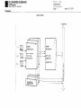
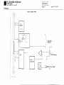
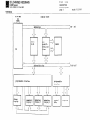
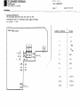
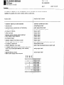
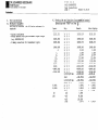
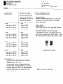
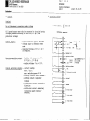
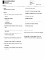
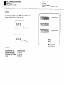
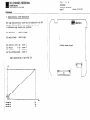
Service-instructions
HEIDENHAN -l-NC114
DR.JOHANNES HEIDENHAIN
Feinmechantk. Optik und Elektronik PrGsionsteilungen
Postfach 1260. D-8225 Traunreut Telefon (086691314
Telex 56831
Telegrammanschrift
DIADUR Traunreut
DR. JOHANNES HEIDENHAIN
D-8225 Traunreut
Telefon (08669) 31-O. Telex 56831
114
TNC
SERVICE INSTRUCTIONS
stand:
Kundendienst
TABLE OF CONTENTS
o IMPORTANT INSTRUCTIONS
o DESCRIPTION
-;Block
Diagrams
0 FAILDIAGNOSTICS
o EXCHANGE
- Control
Exchange
- Board Exchange
- Software
Exchange
01.10.83
114
TNC
IMPORTANT INSTRUCTIONS
DR. JOHANNES HEIDENHAIN
D-8225 Trsunreut
Telefon (08669) 31.O.Telex
56831
stand:
Page 1
01.10.83
Kundendienst
Subject
to change
(without
The TNC 114 contains
sub-assemblies
with CMOS elements.
Although MOS IC's are equipped with an input protection
diode network to eliminate
the build-up
of static
charges,
care must be taken when handling
these elements.
notice)
HEIDENHAIN is constantly
working on further
developement
of
It is therefore
possible
that details
of
its TNC controls.
a certain
control
may differ
slightly
of the control
version which is being described
herein.
For this reason it
may be necessary to request an updated service manual from
us.
The following
requirements
in the work area must be met:
Prior to working with CMOS components or with assemblies
equipped with CMOS elements,
all table coverings,
all operated
instruments
and/or tools,
as well the work personnel,
must be
properly
grounded.
A portable
"MOS-HANDLING-SET" for field
when exchanging
the operating
software
TNC 114.
1) a cable
between
Note
Reproduction
our consent.
of this
service
manual
is not permitted
without
that equalizes
potential
conductive
work surface
service
is necessary
and/or servicing
the
differences
and ground
2) a wristband
that provides
an electrical
connection
between person and conductve work surface
3) a conductive
work surface
114
TNC
DESCRIPTION
Block Diasrams
DR. JOHANNES HEIDENHAIN
D-8225 Traunreut
Telefon (08669) 31.0,Telex
56831
page
Kundendienst
stand:
1
---
L-L
r
iTNC wiring
--
01.10.83
114
TNC
DESCRIPTION
Block Diagrams
Page 2
DR. JOHANNES HEIDENHAIN
D-8225 Traunreut
Telefon (08669) 31-O. Telex 56831
Kundendienst
power
23.6
supply
board
vw
ov
power supply
voltage
supervision
3-
Signal
"N&z"
stand:
01.10.83
114
TNC
DESCRIPTION
Block Diagrams
DR. JOHANNES HEIDENHAIN
D-8225 Traunreut
Telefon (08669) 31-O. Telex 56831
page
stand:
3
Kundendienst
analog
board
A
2
Y
signal
evaluation
00
900
RI
EXE 2x with
ref.-imp.
evaluation
RID1 and
momentary
V.SlWZ
aquisition
X
A
r\
h------v
,-A/D7
01.10.83
114
TNC
DESCRIPTION
Block Diagrams
Page 4
DR. JOHANNES HEIDENHAIN
D-8225 Traunreut
Telefon (08669)
31-O. Telex 5663,
stand:
01.10.83
Kundendienst
analog
output
board
\
+ 15v
P
___-..
is+
'switching
outputs
L
+ 12 v
P
i
A/DO-A/D7
-D-
L
intended
0
. ..+12
value
ov
v
output
DR. JOHANNES HEIDENHAIN
Telefon (08669)
114
TNC
DESCRIPTION
Block Diasrams
D-8225 Traunreut
31-O. Telex 56831
page
5
stand:
-
Kundendienst
6,144 MBZ
display
board
lI!ELA8
address:bus
EPROM
IC-Pl
RAN
withI/OPorts and
Timer
address/data
programmable
display
A/DO-A/D7
programmable,
~interface
X
momentary
display
Y
.-
Al5
EAROM
bus
interface
momentary
-
momentary
display
2
‘/
01.10.83
114
TNC
FAIL DIAGNOSTICS
DR. JOHANNES HEIDENHAIN
D-8225 Traunreut
Telefon (066691 31-O. Telex 56831
stand:
Page 1
01.10.83
Kundendienst
1.
Automatic
fail
test program
2. Internal
The internal
test program
diagnostics
an automatic
fault
With operating
faults,
issued by the TNC 114 which simultaneously
regulator
release contact.
Transducer
is defective
The accompanying momentary position
with a transducer
defect.
Erasing the message:
Switch-off
line voltage:
switch-on
fault
has been remedied.
message is
opens the
LED will
line
-“_
after
switching-on.
Visual control
- All segments of the momentary position
value and
the preset display
must illuminate
together
with the
same intensity.
- All decimal points
of the preset value must illuminate.
The decimal points
of the momentary position
value must
illuminate
from the second decade.
- After approx. 3 sec. the preset values will
be in the
axis display,
the present value display
= 0. Operating
mode El1 with
]is selected.
- The momentary test condition
will
be displqyed
in a
coded manner with the LED's of the q ,a , q , q 1
keys. The lower LED row will
blink with a fault.
The following
ICs are tested one after another:
ROM,
RAM, TIMER.
The following
fault
conditions
may occur:
.
after
q
114, the
illuminate.
the fault
be sent to
fault
coding)
Positioning
direction
error
If for a selected
positioning
direction
the machine
coupling
lever is switched in the false direction
the
feed will
be switched-off
after
200 lun of traversing.
A U-shaped symbol will
appear in the display.
1key: restart
and
Erasing the message: press the
bring the cobplinq
lever in the
correct
position.
q
begin
blink
voltage
Defect in the electronic
Faults of this type are coded by the TNC
lamps over the reference
point keys will
switching-on
Erasing the message: if after
the TNC 114 must then
message reappears,
the factory
for repair.
(with noted lamp
will
x
0
0
x
0
x
0
x
0
x
0
0
x
x
0
0
0
0
x
x
x
x
0
0
0
0
0
0
0
0
x
x
ROM error
RAM error
timer 1 (Q22). counter
, counter
timer 1
timer 1
, counter
timer 2 (Q261, counter
timer 2
, counter
timer 2
, counter
0
1
2
0
1
2
(Pin
(Pin
(Pin
(Pin
(Pin
(Pin
9-X forwards)
15-Y
'
)
18-Z
w
)
9-X backwards)
15-Y
u
18-Z
n
114
FASL DIAGNOSTICS
DR. JOHANNES HEIDENHAIN
D-8225 Traunreut
Telefon (086691 31-O.Telex
TNC
56831
stand:
Page 2
01.10.83
Kundendienst
3. Failure
localization
The following
directions
are only valid
if the
prerequisite
that all secondary power supply voltages
are present,
is met!
power supply
board
soldering
6
+ 5v Q
ov
8
terminal
6
+5v
7
ov
8
u
9
ov
13
+15v
17
"N&z d"
,i~ 1
L
21@
,,,,,,
,,
,,
,,.,.
,,, ,., ,,~,,,
,,.,. ,,,,
,,, ,..,
I
LED
LED
-12v
18
-15v
19
-30v
4,5
200
voltage
23,6V-
10,ll
20,5Vm
20.21
37,5v+
DR. JOHANNES HEIDENHAIN
D-8225
T&ion
TNC
FAIL
Traunreut
(08669) 31-O. Telex 56831
114
DIAGNOSTICS
Page 3
stand:
01.10.83
Kundendienst
For reasons
of complexity
of the interdependent
control
functions,
regarding
the possible
fail
source
location
serves
as guide only.
Occurinq
fault
the
Possible
-
transducer
supervision
system
addressed
counting
error
counting
direction
switch-over
not functioning
no reference
impulse
key does not function
control
LED dark
momentary
position
display
faulty/undefined
preset
display
faulty/undefined
set function
faulty
reference
values
are not/faulty
stored
direction
supervision
does not respond'
no standstill
supervision
no/faulty
momentary
value output
no EMERGENCY OFF/traversing
direction/axis
relays
closed
loop release/speed
momentary
value
internal,
external
- approach
behaviour
faulty
- coded failure
display
after
switch-on:
following
fault
X,Y,Z
x
x
x
x
location
transducer
system/analog
board
analog/display
board
power supply/analoq
board
transducer
system/analog
board
display
board
display
board
display
board
display
board
display
board
display
board
power supply/analoq
board/analoq
display/analog
board
manual feed potentiometer/analog
analog
output
board
analog
output
board
!amQq
x
information
x
x
x
x
x
x
x
x
display
display
analog
analog
analog
analog
analoq
analog
board
board
board
board
board
board
board
board
output
board
output
board
TNC
114
FAIL DIAGNOSTICS
Test Instructions
Page 1
DR. JOHANNES HEIDENHAIN
D-8225 Traunreut
Telefon (08669) 31-O. Telex 56831
stand:
01.10.83
Kundendienst
4.
4.1
Test instructions
Necessary
equipment
For testing
purposes,
required:
4.2
the
following
- digital
multimeter
- rotary
encoder
with photo-element
(e.g.
MINIROD 450)
- 2 dummy connectors
for transducer
equipment
Testing
the set function
of an assembled
Operating
mode "HAND" and key q :.
is
Input:
11111.111
signal
inputs
control
output
15555.555
16666.666
19999.990
.l
1.
11.
111.
1111
11111
11111
-19876.543
-12345.678
0.0001
0.0009
10
100
preset:
Key:
x. y,
x. y.
X8 y,
x, y,
x, y,
x, y,
x, y,
x, y.
x, y,
x, y,
x, y,
x, y,
x. y.
x, y,
x. y,
z
z
z
z
z
z
z
z
z
z
z
z
z
z
z
0,01/0,005
Inch
0,01/0,005
CE/X, Y,
x, y, z
x, y. z
Inch
D/2
-D/2
+D/2
Inch
mm
mm
Z
Axis
display:
11111.115
11111.115
15555.555
16666.670
15555.555
16666.670
19999.990
0.100
1.000
11.000
111.000
1111.000
11111.000
-11111.000
-19876.545
-12345.680
-12345.680
- 486.0504
- 486.0504
0.0000
0.0002
0.0010
0.025
5.000
95.000
100.000
3,937o
19999.990
0.100
1.000
11.000
111.000
1111.000
11111.000
-11111.000
-19876.545
-12345.680
-12345.68
- 486.0505
- 486.0504
0.0000
+
0.0002
+
0.0010
+
0.025
+
0.0010
TNC
114
FAIL DIAGNOSTICS
Test Instructions
page 2
DR. JOHANNES HEIDENHAIN
D-8225
Traunreut
Telefon (08669) 31-O. Telex 56831
stand:
01.10.83
Kundendienst
Storage
1. Level
X-axis
X-axis
Z-axis
2.
3.
4.
Switch-off
line
then switch-on
switch-on
select
operating
mode.
values must be
function
voltage
again. After
the INCH
The following
displayed:
4.3 Testing
the dessembled
control
Supervision
function
Disconnect
transducer
connections
for X, Y and Z axes:
The momentary value display
must blink
in the same
order of disconnection.
1. Level
set to 11111.115
X-axis
437.4454
set
to
set
to 13333.335
Y-axis
Z-axis
481.1900
524.9344
Level
X-axis
Y-axis
Z-axis
612.4234
656.1678
12222.225
Level
X-axis
Y-axis
Z-axis
set to 14444.445
set to 15555.555
set to 15555.665
Level
X-axis
set
to 17777.775
Y-axis
set
to
Z-axis
set to 19999.995
Level
X-axis
Y-axis
z-axis
set to 10000.000
set to 12345.675
set to 19876.545
2.
3.
18888.885
Level
X-axis
Y-axis
Z-axis
4.
Level
X-axis
Y-axis
Z-axis
568.6788
Counting function
Connect rotary
encoder to X-axis input dummy connectors
on X and Z axis. Test the counting
function
in~positive
and negative
directions
of all axis and decades.
On the backside of the unit,
the counting
direction
for
every axis can be selected
using the DIL switch 1, 2 and 3.
The counting
direction
is positive
when switch is closed.
699.9124
743.6568
787.4014
counting
direction
393.7008
486.0502
782.5410
Control
function
- Position
a positive
and negative
value in absolute
dimensioning
(e.g. + 100, - 100)
- Position
several values in incremental
dimensioning
in both positive
and negative
directions,
in all axis.
- Traverse a larger
value (lOOO), test feed potentiometer
during the positioning
as well as the STOP key and
traverse
functioning.
Repeat the test
for
Y- and Z-axis.
positive
TNC
114
FAIL DIAGNOSTICS
Test Instructions
Page 3
DR. JOHANNES HEIDENHAIN
D-8225 Traunreut
Telefon (08669)
31-O. Telex 56831
stand:
01.10.83
Kundendienst
Reference pulse evaluation
Select operating
mode "HAND". Set axis to reference.
Press
the FtEF key, REF diode must laminate.
Rotate rotary
encoder
Shaft over reference
impulse,
(REF LEDs off) press REF key,
press again and hold.
Rotate rotary
encoder shaft until
reference
impulse stops
the display.
The displayed
impulse
example:
count
value
must evaluate
x signal
to:
subdivision
x evaluation
x counting
istep
Repeat the test with negative
rotation
directions.
Repeat test for Y- and Z-axis.
2 x
4x
5w
Repeat the test
axes.
100 x 2 x 4 x 5 um = 4.000
(displayed
positioning
values
and positive
Standstill
supervision
test
Connect rotary
encoder on transducer
syste&n X-axis input and
dummy connectors
on transducer
Y- and Z-axis inputs.
Start X-axis postioninq.
Connect rotary
encoder to transducer
system Y-axis input and
rotate
shaft.
(uuuuuuuu
The error message
)
appears in
the preset display
for a displayed
momentary value of 3205
w.
MINIROD 450
100 impulse/rotation
TNC 114:
signal subdivision
evalution
counting
step
Direction
supervision
test
Connect rotary
encoder to transducer
system input X-axis and
dummy connections
on transducer
input X- and Z-axis.
Select
operating
mode "absolute
dimensioning".
For example:
enter + 1000 and initiate
traversing
with the X-key.
Rotate rotary
encoder counter clock-wise
(minus direction).
With a value
) - 205 w the segments b, f, and q must luminate
on the preset display
for all decades. (uuuuu~uu
)
in positive
and negative
directions
for
all
value)
Axis supervision
The axis supervision
is active on all 3 axes within
a
distance
of 205 wn. The standstill
of the remaining
axes that
are momentary not controlled
is supervised.
The direction
of
the momentary controlled
axis is supervised.
1.,.-___._l..-,..--,“-
,, .,.,, ,,,,,
_
114
TNC
EXCHANGE
Control
Exchange
Page 1
DR. JOHANNES HEIDENHAIN
D-8225 Traunreut
Telefon (08669) 31-O. Telex 56831
Kundendienst
2. Interface
1. General
wiring
Caution!
DO not disconnect
connector.s
under
CONTROL
voltage
All inputs/outputs
must only be connected to circuits
having
voltages
produced according
to VDE 0100/5.73
§8. (low
protection
voltage)
Control
Momentary
Control
- input resistance
approx: 100 kOhm
- voltage
input to determine
feed
rate
- regulated
voltage
of 0 to + 12 V
is required.
inputs:
position
switching
multipoint
output:
outputs:
- loading with respect to 0 V:
R ?. 2.4 k , C 2 50 nF
- analog voltage:
0 to + 12 v.
- contact
loading:
48 V / 0.3 A
switching
power 10 W
max.
- working contacts:
axis release
- working contact:
regulator
release
- switch-over
contact:
traversing
direction
- switch-over
contact:
momentary
traversing
speed internal/
external.
X
USER
terminal
stand:
01.10.83
114
TNC
EXCHANGE
Control
Exchange
Page 2
DR. JOHANNES HEIDENHAIN
D-8225 Traunreut
Telefon (08669) 31-O. Telex 56831
Kundendienst
3.
Exchange
1. Note operating
program-nr.
and ident-nr.
of the control!
2. Disconnect
mains coupling
of the control.
3. Isolate
connections
on the multipoint
terminal.
Order (l-22)
and note wire colors.
4. Disconnect
transducer
systems for X, Y, 2.
Assembly
Important:
in reverse
order.
Observe correct
positioning
selector!
Fusing: T 0.4 A
of the line
voltage
stand:
01.10.83
114
TNC
EXCHANGE
Board Exchange
Page 1
DR. JOHANNES HEIDENHAIN
D-8225 Traunreut
Telefon (08669) 31-O. Telex 56831
1. General
Observe MOS protection
10) Remove analog
01.10.83
board.
procedures.
11) Disconnect
2.
output
stand:
the analog
board
supply
voltage.
bolts
of the analog
bolts
of the display
Exchange
12) Remove the 5 mounting
1) Remov& the 4 Phillips
backside.
mounting
screws
13) Disconnect
2) Service block including:
- front plate
- display
board
- analog board
remove from frontside.
3) Disconnect
board.
DIL-switch
4) Disconnect
grounding
output board.
6)
Disconnect
outputs,
7)
Disconnect
16) Disconnect
connector,
located
on the analog
located
on the analog
system connector
board.
for
voltage
8) Remove the 5 Phillips
output board.
mounting
9) Disconnect
flat
output board.
connector
cable
board.
to the analog
screws
located
the 4 keyboard
17) Remove display
Assembly
in reverse
the correct
board.
connectors.
board.
order.
location
of the LEDs when assemblying.
X, Y, Z,
flat
cable connector
for control
input/
located on the analog output board.
the supply
cable.
15) Remove the 5 mounting
Observe
5) Disconnect
transducer
located on the analog
flat
14) Remove analog
connector
board.
oil the control
board.
of the analog
on the analog
The power supply is offered
complete inclusive
line
transformer
and inclosure
backwall
as replacement
part.
114
TNC
EXCHANGE
Software
Exchanqe
Page 1
DR. JOHANNES HEIDENHAIN
D-8225 Traunreut
Telefon (08669) 31-O. Telex 56831
stand:
01.10.83
Kundendienst
1. General
The operating
EPROM (IC-Pl,
program
for
Q28) on the
the TNC 114 is
display
board:
program
xxx
ident
xxx
contained
in
\
an
number
xx
pr.g~.-k&t
stand
display
IC program
xxx
xxx
ident
board
number
xx
IC program
-merit nr.
stand
2. Program
program
description:
program
ident
number:
IC program
ident
number:
issue :
standard
program
212 927 02
212
927 1B
04.09.1981
,_,,.,-.._~--,-.,~._ ,.--“__
.
,‘,,...,.,
-
114
TNC
EXCHANGE
Software Exchange
Page 2
np. JOHANNES HEIDENHAIN
!25 Traunreut
fon (08669) 31.0,Telen
56831
Kundendienst
3. Characteristic
curve
description
The ramp characteristic
curve can be adjusted
by the DIL
switches
S1/2 and S1/3 on the analog output board.
(4 different
ramp lengths
are possible)
DIL switch
up
DIL switch
down:
DIL
DIL
DIL
all
:
switch
closed
switch
open
switch 2 and 3 up : curve
3 up : curve
switch
up : curve
switch 2
DIL switches down : curve
Ramp characteristic
’
1
2
3
4
curve
i
.I
analog
TNC 114
,,,,,,,
1
‘1
output
board
stand:
01.10.83
114
TNC
EXCHANGE
software
Exchange
Page 3
DR. JOHANNES HEIDENHAIN
D-8225 Traunreut
Telefon (08669) 31-O. Telex 56831
Kundendienst
4.
Program
Important:
exchange
observe
MOS
protection
procedures.
In order to exchange the operating
program,
board must be demounted from the control.
Necessary
tools:
- IC extract/insertion
- small screwdriver
the display
tool
- remove EPROM from display
board using extraction
- place EPRQM onto MOS protection
mat
- insert
new EPROM correctly
using insertion
tool
Important:
IC must be pointing
- The inserted
direction
as the remaining
IC's
board.: b
- Before installing
visually
check if
the IC socket.
in the same
on the display
the board into the control,
all the IC pins are contacting
After an operating
program exchange the program
changed on the backside of the control.
,
tool
nr.
has to be
stand:
01.10.83