1
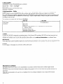
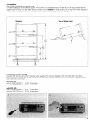
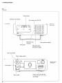
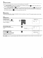
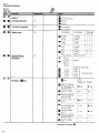
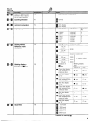
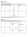
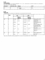
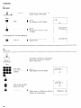
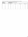
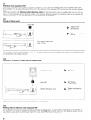
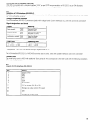
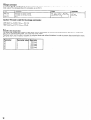
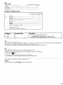
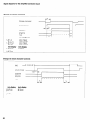
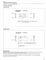
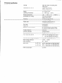
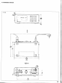
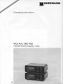
HEIDENHAIN
Operating Instructions
VRZ 401, VRZ 405
HEIDENHAIN Display Units
Page
Contents
-~1. Items supplied _~~~~-~
_ _
2. Brief description
- Outline .-._
3. Notes ~-_---~~~~~~~~~
4. Installation
-~-.-- ~.~~~~
-- _
-~5. Selection of mains voltage
_
-.-~
~~
6. Starting procedure ..-- .. ~-.
6.1 Controls .-~
...-.-~.. ~~~~ - __
-~~
6.2 Switch-on oi counter ~~_
6.3 Setup functions ~~-~.~~~~~ ~~6.3.1 Parameter-entry _~~~~~ 6.3.2 Parameter Overview
~~.
6.3.2.1 VRZ 401 -.~
6.3.2.2 VR Z 405 ~~ ~~~~~~
6.3.3 Functions/Operatrng modes
6.3.3.1 Norninal/Dianreter display (wrth VRZ 401) ___..
~~
-.6.3.3.2 Counting drrection
6.3.3.3 mm/inch-disf,lay -._
--~
6.3.3.4 Display stcp
-_
6.3.3.5 Settrng of gratirrg period - normal/distance-coded
6.3.3.6 Zeroing wtth CL key/Blinking display
--.-~~~
7. Operation
-- ~~~~
7.1 Zero reset _---..~~~~~~~
-.- _
7.2 Datum sel .-___~~~~~~~ ~~
_
-~~..
7.3 Reference mark evaluatiori REF _
- ...~~~
7.3.1 Storage of daturn point - _
7.3.2 Retrieval 01 correlation Plunyer position/Display value
7.3.3 Working wrthout reference mark evaluation REF ~
~~~-8. V.24/RS-232-C-interface
(VFL!! 405)
8.1 Definition of V.24-interface (RS-232.C)
8.2 Layout of V.24-interface (RS %32-C)
- -~~~~
8.3 Storage commarld ~~~ ~~ -- 8.4 Transfer rate (baudrale)
-~~
8.5 Data format ---.~~~~
~~~
- 8.6 Interruption of data transfer
_
8.7 Data output ~-.-- -~.--~~ ~~~ - 8.8 Connection of external units (wiring)
-.~
8.9 Connecting cable .--~.~~~~~
~9. Error messages __..__..10. Technical specifications
~~~~ ~_ ~~--.
11. Dimensions
.~
~reference marks ~_~
~~~~~
-.~
4
4
4
~~ 5
~~ 5
6
6
.7
7
7
8
8
9
10
10
10
~~1 1
11
12
13
14
14
14
16
16
16
16
17
17
17
18
18
19
19
19
21
21
22
23
24
3
1. Items supplied
HEIDENHAIN counterVRZ 401/405 (type as ordered)
Fuse for 200
240 V- incorporated
Fuse for 100
. 140 V- in package
Mains cable
Operating Instructions with Parameter Chart
Certificate of Inspection
2. Brief description
- Outline
HEIDENHAIN linear encoders with 10 um, 20 um, 40 um (only with VRZ 401) or 100 um grating period, HEIDENHAINMETRO gauges as weil as HEIDENHAIN rotary encoders with sinusoidal output Signals are suitable for connection.
The output Signals are amplified, interpolated within the HEIDENHAIN counter and subsequently counted in accordance with
the sign. The measured value is displayed via a seven-digit 7-Segment digital display. Owing to the gold-coloured numerals,
the display is easy to read.
The counters are provided with the following
functions:
VRZ 401
VRZ 405
V.24/RS-232~C
Data output
Zero reset
Datum set
Reference mark evaluation REF of individual and distance-coded
reference marks
mm/inch calculator
selectable display step
selectable counting direction
selectable aratina period
Functions
3. Notes
Counters VRZ 401/405 correspond to protection class I of the German VDE regulations VDE 0411 and have been built and
checked in accordance with DIN 57411 part l/VDE 0411 part 1 “protective measures for electronie measuring units’: In Order to
maintain this condition and to assure safe Operation please adhere to the notes and instructions as contained herein.
Maintenance
These instructions contain all details required for commissioning and Operation of the counters. The units are maintenance-free.
In the case of any fault or failure we recommend return of the counter to our works Traunreut or to your local supplier.
Caution!
DO not engage or disengage any connectors
Manufacturer’s
whilst under power.
certificate
We hereby certify that the above unit is radioshielded in accordance with the West German official register decree
1046/1984.
The West German postal authorities have been notified of the issuance of this unit and have been granted admission for
examination of the series regarding compliance with the regulations.
Information:
If the unit is incorporated by the user into an installation then the complete installation must comply with the above
requirements.
4
4. Installation
The counter is designed as a desk-top unit.
For easier readings it tan be tilted by approx. 14O by means of a collapsible stand. The feet of the unit are provided with M5
tapped holes for fixing to a base plate. Several counters tan be stacked by simply putting one on top of the other. Slipping of
stacked counters is prevented by the housing rim aswell as by small protrusions in the housing cover.
Use of tilting stand
Stacking
5. Selection of mains voltage
Counters VRZ 40X are set to 220 V Operation when supplied. This may be changed to 100, 120, 200, 240 V as follows:
Remove mains fuse holder (Fig. 1) and set voltage selector to the required rating by means of a coin (Fig. 2). Replace mains
fuse holder with correct fuse.
with VRZ 401
Fuse for 200/220/240
Fuse for 1 00/120/140
VV-
0.125
0.25
A slow-blow
A slow-blow
VV-
0.16
0.315
A slow-blow
A slow-blow
with VRZ 405
Fuse for 200/220/240
Fuse for 1 00/120/140
6. Starting
procedure
6.1
Controls
Digital display
Operating mode display
Print release with VRZ 405
Front Panel
Transfer of
entry value
I
Keyboard for entry values
and Parameter selection
Reference mark
evaiuation
Tiiting stand
Clear entry value,
Parameter call and
zero reset of display
Mains fuse holder
\
\
Mains voltage selector
Rear Panel
-
Mains switch
f-i\
\ Ill
I
Mains socket
6
I
/
I
Flange socket with VRZ 405
for V.24jRS-232-C data output
and storage
Flange socket
Transducer
6.2
Switch-on
of counter
The digital display flashes after switch-on (mains switch at counter rear). This signalizes that the displayed value does not correspond to the last selected datum value due to the preceding power interruption.
a) With initial activation
the flashing of the display tan be cancelled by pressing the
ready for setting the operating mode (see item 6.3).
b) With any futther
activation
q
-key twice. The counter is now
press
. -key once. The digital display illuminates; flashing of the .
display field requests
m
m
traversing the reference mark of the encoder for retrieval of the last selected correlation between encoder Position and
display value (see item 7.3.2). If this correlation is effected via zero reset or datum set after probing of a mechanical limit
stop (reference surface), the
-key is to be pressed twice (see 7.3.3).
6.3
Setup functions
VRZ 40X is provided with a number of selectable functions
mined by entry of Parameter values.
(see tables as of page 6). The required operating mode is deter-
6.3.1
Parameter-entry
Parameter call-up
Simultaneous pressing of
press (e. g.)
display (e. g.)
and of the number of the selected
Parameter. The Parameter value last
entered is displayed.
Enter Parameter value
Enter value for required operating
mode.
1-t -1
i- II
0
I
Storing
Parameter
I
Parameter
Parameter value
value
, the selected parameter value is stored. The required
operating mode is now set.
Non-volatile
storage of entered Parameter values. When resuming Operation the counter operates in the last entered mode.
7
6.3.2
Parameter
Overview
6.3.2.1
VRZ 401
PO
Radius/Diameter
display
Counting
mm/inch
direction
conversion
a
Radius display
0
Diameter display
q
normal
m
inverse
P2
mm display
inch display
Display
q +m
step
Grating Periodl
Reference mark
evaluation
Blinking
display
Function
of
q
-
P3
mm display
P4
Gratina Period
P5
Function of
Parameter
P4 1 PO
/ Reference mark
inking display
-7
key
p
Clears the drsplay
;
p
Sets the display
to “0”
p
Clears the display
and redisplays the
previous value
q
0
m
q
q
0 yes
0 yes
0 no
Sets the display
to “0”
0 yes
0 no
Clears the display
and redisplays the
previous value
0 yes
Sets the display
to “0”
0 no
Clears the display
and redisplays the
previous value
Sets the display
to “0”
Transfer
8
inch display
to memory
0 no
0 no
/
I
0 no
@
0 yes
0 no
6.3.2.2
VRZ 405
Output of blank lines
between value Outputs
via the data interface
PO
Counting
Pl
mm/inch
Display
direction
conversion
step
P2
Enter number of blank lines
ß
normal
0
inverse
0
mm display
q
inch display
mm display
P3
inch display
Parameter
P4
0
Grating Periodl
Reference mark
evaluation
P4
ß-4
Grating Period
10 um
100 um
20 um
0
Reference mark
Single
200 um
q +-D
Blinking
Function
display
of
q
-
ß
ß
20 w-
1000
0
ß
E#!!!!i
10 pm
2000
20 pm
2000
Function of
P5
(9 W
key
Blinking display
after
Fault
0 yes
0 yes
Sets the display
to “0”
0 yes
0 yes
Clears the display
and redisplays the
previous value
0 yes
0 no
Sets the display
to “0”
0 yes
0 no
Clears the dispiay
and redisplays the
previous value
0 no
0 yes
0
Sets the display
to “0”
0 no
0 yes
fl
Clears the display
and redisplays the
previous value
0 no
0 no
Sets the display
to “0”
0 no
0 no
0
q
q
a
P6
x grating period
Switch-on
q
Baud Rate
7
with
Clears the display
and redisplays the
previous value
q
q +ß
1 Distance-coded
1000
10 um
q
150 baud
ß
300 baud
ß
q
q
600 baud
1200 baud
2400 baud
Transfer
to memory
M
9
6.3.3
Functions/Operating
6.3.3.1
Nominal/Diameter
modes
display (with VRZ 401)
Via Parameter 0 the VRZ 401 tan be converted from Nominal display (display value corresponding
display (value corresponding to double the travel).
Parameter
Parameter value
PO
0
to travel) to Diameter
DisrAav value
Travel
5.000
10.000
PO
Exception: When connecting
encoders with 40 um grating pitch the Parameter value PO 1 must principally be set.
The display value then corresponds to the travel.
6.3.3.2
Counting direction
Conversion of the counting direction is effected via entry of the value of Parameter Pl
Parameter
Parameter value
Pl
0
Scanning head/Plunger
movement
Countina mode
- 0.0010
mm
- 0.0005 mm
0.0000 mm
0.0005 mm
Pl
1
0.0010
mm
- 0.0010
mm
- 0.0005 mm
0.0000 mm
0.0005 mm
0.0010
mm
positive
negative
6.3.3.3
mm/inch-display
The measured value tan be optionally displayed in “mm” or “inch”. Determination
This is also possible during measuring.
is effected via value entty in Parameter P2.
Parameter
Parameter value
Display
Unit
P2
0
25.4000
mm
P2
.l
1 .ooooo
inch
INCH illuminates
6.3.3.4
Display step
The display Step tan be either set to depending
Parameter
P3
P3
P3
P3
Parameter
value
0
1
2
3
on the connected
measuring System
for encoders with
Display step
mm
Nominal
Diameter
(only on
VRZ 401)
Nominal
Inch
Diameter
(only on
VRZ 401)
0.000 5
0.001
0.000 02
0.000 04
IO um grating periodl
36 000 lines
0.001
0.002
0.000 05
0.0001
0.002”
-
0.0001”
-
20 um grating periodl
18 000 lines
40 um grating periodl
9000 lines
0.001
0.002
0.000 05
0.0001
IO/20 um grating periodl
18 000/36 000 lines
0.002”
-
0.0001”
-
40 um grating periodl
9000 lines
0.005
0.01
0.000 2
0.000 4
100 um grating periodl
3600 lines
0.01
0.02
0.000 5
0.001
200 um grating periodl
1800 lines
0.02”
-
0.001”
-
900 lines
0.01
0.02
0.000 5
0.001
0.02”
-
0.001”)
-
100 um grating periodl
3600/1800 lines
900 lines
“Valid only for VRZ 401; here the Parameter PO is to be set to the Parameter value 1 (Diameter display)
11
6.3.3.5
Setting
of grating
period
- normal/distance-coded
reference
marks
Encoders with IO um, 20 um, 40 um (only with VRZ 401), 100 um or 200 um and rotary encoders with various line counts are
connectable to the VRZ 401/405 provided that they have sinusoidal output Signals. Via Parameter 4 the counters are adjusted
to the grating periods/line counts and the various reference marks - normal or distance-coded - are taken into account.
Linear encoders
Parameter
Parameter
P4
0
Reference
marks
normal
1
P4
P4
2
P4
P4
Rotary
value
distance-coded
Grating
period
Encoder
10 um
METRO
Length gauge
LID 300/310/
320/350/400
100 um
LB 326
LI DA 2011225
20 um
LS 107
LS 403/404
LS 703/707
ULS 300
LID 320/400
40 um
LIDA 190/40
200 um
LIDA 190/200
10 um
LS 101c
3
20 um
LS 107c
LS 303c
LS 403 c/404 c
LS 603C
LS 703 Cl704 c
ULS 3ooc
4
10 um
LID 351C, LID 311C
encoders
Parameter
Parameter
P4
0
value
Line count
Rotary
36 000
ROD700
ER0 7251815
ROD 151/450/456
RON 1551455
MINIROD 450
3600
P4
1
ROD 250/700
RON 2551705
ER0 7251815
ROD 151/450/456
RON 1551455
MINIROD 450
ER0 1251
18 000/9000
1800/900
Since the VRZ 401/405 has no automatic
(e. g. 2 revolutions: 720.000”).
reset after 360°, counting
encoder
is continued
beyond 359.999
for repeated revolutions
Rotary encoders that serve to determine lengths, traverse or feedrates tan also be connected. For such applications it is
necessary to take the transmission ratio into account (rack and pinion, nut and spindle or circumference of the friction wheel)
in addition to the interpolation factor and line count.
Caution:
With the re-adjustment
P4 0 + 1
P4 1 -f 0
12
of the grating period all values momentarily
Values are doubled
Values are halved
stored in the display unit are simultaneously
changed
6.3.3.6
Zeroing with CL key/Blinking
display
Two functions are adjustable via Parameter P5:
Zeroing with the CL key
The counter tan be easily zeroed by pressing the
values 0/2/4/6
the n
and 0@
key if the Parameter value is adjusted to 1/3/5 or 7. With Parameter
R!
keys must be pressed.
Display blinking
Display blinking after power interruption
Parameter
P5
Parameter
or switch-on
value
or due to faults tan be deactivated.
Zeroing
CL key
no
w
no
w
no
w
no
w
with
the
Display blinks
switch-on
after
I fault
w
es
_-------
w
w
w
w
no
no
no
no
l
no
no
w
es
no
no
13
7. Operation
7.1
Zero reset
Counter tan be reset to zero at any
random location of the travel.
Press
0 key
h
SET on
Zero appears on left of display.
b
SET off
Zero as datum appears on right
of display.
b
Zero appears in display upon
release of key.
t
q
Transfer key
i-t
‘J.
SET
1-r 1-r 1-t l-IJ-1
1-.- ll Ir - II - Il - I
or. if Parameter P5 1 has been addressed
m
7.2
Datum
Clear key
I-I l-l l-l l-l 1-1
l-.-fl II - Ill1- - I
set
Any random number (e. g. the Nominal
dimensions) tan be set as reference
datum (initial value).
Press
Enter datum
e.g. 80.001 mm
(3.150 in)
SET on
Value appears on left of display
1-11-1 I-Ir-l
-l-llIll~l
- -.-
I
I
SET
Clear key for wrong entry
IJ r-11-1 l-l
IIIIIIII
- -.-
Entry of neg. sign after
datum set, if reqd.
Transfer key
I
I
SET
b
SET off
Datum value e.g. 80.001 mm (3.150 in)
appears on right of display
14
-_ .._-~~
l-l l-l
l-l I-I
11 lJ,lJ
1-l
11-1
11-1
The datum value is rounded off in accordance with selected display step and mm or inch display.
entered
transferred
datum
with display step
/datum value
value
(last decade)
(last decade)
0.0005
0
1
2
3
4
5
6
7
8
9
0
0
0
0
0
5
5
5
5
5
mm
0.001 mm
0.00002
0
1
2
3
4
5
6
0
0
2
2
4
4
B
i
9
8
8
inch
0.00005
inch
0
0
0
0
0
5
5
5
5
5
15
7.3
Reference mark evaluation REF
After power interruption the correlation between the Position of the machine carriage/plunger and the display value is lost,
This correlation tan be easily retrieved with the aid of the reference mark evaluation REF by traversing the encoder reference
mark.
With linear encoders with distance-coded reference marks the absolute Position value is available after only max. 20 mm
travel, i. e. after traversing of two reference marks. In this case the distance between the reference marks is not constant but
defined by Variation, i. e. the absolute Position tan be determined by calculation.
7.3.1
Storage of datum Point
press REF
b
Display Stops
REF flashing
b
Display simultaneous
REF on
Zero reset or datum set
(see 7.1/7.2)
With activated reference mark evaluation - REF on - all datum value entries are calculated with relation to the reference mark
and entered into non-volatile memory.
7.3.2
Retrieval of correlation
Plunger position/Display
value
II
ut
P
0
Cl
1
1
I
switch on counter
b
REF dark
press REF
b
REF flashes
Display Stops
b
Display simultaneous
REF on
I
traverse reference mark
Display value is now referenced to the last datum set in REF Operation
7.3.3
Working without
reference mark evaluation REF
Some applications provide a fixed mechanical limit stop as reference plane. In these cases the reference mark evaluation is
not required. lt tan easily be disabled by pressing the REF-key twice after counter switch-on. The reference System tan be
retrieved by probing the measuring table surface, a master piece, and zeroing or datum set.
16
8. V.24/RS-232-C-interface
(VRZ 405)
VRZ 405 is provided with a Standard intetface “V.24” as per CCITT recommendation or RS-232-C
Inputs for the storage command are additionally provided at the same flange socket.
8.1
Definition
of V.24-interface
(RS-232~C)
The following important criteria are provided because units with different Signal levels, connector
as “V.24-compatible
Systems’:
as per EIA-Standard.
layouts etc. are on the market
Voltage compatible
interface
The V.24-intet-face (RS-232-C) processes Signals with voltage levels. Current interfaces (e. g. 20 mA) cannot be connected!
Signal
designations
and levels
Signal
Meaning
Data Signals:
TXD”
RXD”
Transmit Data
Receive Data
Control Signals:
DTR
RTS
Data Terminal Ready
Request to Send
Verification Signals: DSR
CTS
Data Set Ready
Clear to Send
Logic-level
Operating
“l”:--3v...-l5V
“0”:+3V...+15V
-5v...-l5V
+5v...+15v
level
~~
* Designations “TXD, RXD” are derived through negative level for “1’:
Series data transfer
The V.24-intetface (RS-232-C)
of VRZ 405 transmits data in series. Units with parallel interfaces cannot be connected!
Transfer code
The code being used is ASCII with additional “Even parity bit”. This corresponds
STX: end of data transfer
8.2
Layout
Pin
1
2
3
4
5
6
7
of V.24-intetface
to the ISO-Code with the following
exceptions.
(RS-232-C)
Signal
Chassis G N D
TXD
RXD
RTS
CTS
DSR
Signal GND
11
0 V for storage (Pin 18 or 25)
18
Storage via pulse control (TTL-level)
20
DTR
25
Storage via contact close
17
8.3
Storage command
At contacts PIN 18 and PIN 25 the storage commands tan be entered via pulse control or contact close for activation of the
data output. The corresponding 0 V connection is on PIN 11.
PIN
Function
PIN 18
PIN 25
PIN 11
Storage via pulse control
Storage via contact close
ov
Level
Duration
Caution: TTL-level is valid for the storage commands:
LOW-level UeL $0.4 V at lslnk- 0.2 mA
HIGH-level UeH 2 2.7 V at IsouIce20 uA
8.4
Transfer rate (baud-rate)
The baud-rate signifies the number of bits which tan be transmitted per second. The V.24-interface (RS-232-C) of VRZ 405
permits the following baud-rates: 150, 300, 600, 1200, 2400.
Peripheral units must be able to process the selected baud-rate without limitations in Order to prevent data transmission errors.
The baud-rate tan be selected via Parameter entry.
18
8.5
Data format
The individual characters comorise
Start-Bit
7 Data-Bits
Even-Parity-Bit
1 Stop-Bit
Sequence
of Character
output
I-123.4565?1
I
Sign (+)
Decade 7
Decade 6
Decade 5
Decimal Point (at correct place)
Decade 4
Decade 3
Decade 2
Decade 1
Unit/Fault message (? if fault)
(Empty space if mm, n if inch)
“Carriage return” (CR)
“Line feed” (LF) (number selectable)
The number of additional “line feed” commands
Parameter
Parameter
PO
e. g. PO
PO
X
1
5
value
(blank lines) is selectable between 0 and 99 via Parameter entry.
Description
x = number of additional blank lines LF
one additional line feed between 2 printouts (2xLF)
five additional line feeds between 2 printouts (6xLF)
8.6
Interruption
of data transfer
With normal commercially available data receivers (e. g. Printers) it is possible that the data transfer has to be interrupted
time to time (e. g. printing procedure or “overflow” of Character memory).
Data output of VRZ 405 tan be stopped and restarted via a Signal to the interface input CTS.
from
8.7
Data output
Data output is effected via a built-in intermediate (buffer) memory.
Transfer of the currently displayed value to the intermediate memory is effected by
a) pressing the
q
‘. -key
b) entry of a storage command (contact close or TTL-level)
c) transmittance of check Character Control B (STX) from data receiver
After a delay t2 the data are provided at the interface output TXD. The duration of data transfer is dependent
baud-rate and the required number of line feeds (LF).
Caution:
For the storage command lTL-level
on the selected
is valid, not V.24-level!
19
Signal diagrams
Storage
for the simplified
via storage
connector
layout
command
Storage command
I
Actual storage
t1
--DSR/DTR
RTS/CTS
TXD
for storage
fE L 1 ps
BI5 ms
tl 5 0.8 ps
5 5 ms
pulse
make
pulse
make
mm-display
t2 5 12 ms
-
via:
tz
t3
trigger
contact
trigger
contact
inch-display
5 29 ms
t3 2 IO ps
Storage
via check
Character
Control
I
RXD
actual storage
DSR/DTR
RTS/CTS
TXD
mm-display
t, 56ms
t2 5 7 ms
t3 L 10 ps
20
B
inch-display
$15ms
516 ms
8.8
Connection of external units (wiring)
Depending on the make of the employed data units, different wiring of the connection
Standard connector layouts are being used.
cables mrght be required. Some non-
Commonly used wiring:
Complete wiring
V.24 connection
of VRZ 405
CHASSIS
GND
TXD
RXD
RTS
CTS
0
external unit
CHASSIS
0
ix:
5
:zx-,
z
SIGNAL
SIGNAL
GND
TXD
RXD
RTS
CTS
DSR
GND
DTR
Signals RTS, CTS, DSR and DTR must have operating level “1”
(+ 5
+ 15 V) for data transfer.
Simplified wiring
V.24 connection
of VRZ 405
CHASSIS
SIGNAL
external unit
1
2
3
4
5
6
7
20
GND
TXD
RXD
RTS
CTS
DSR
GND
DTR
CHASSIS
SIGNAL
GND
TXD
RXD
RTS
CTS
DSR
GND
DTR
Signals RTS, CTS, DSR and DTR constantly have working
level “1” (+ 5
+ 15 V) due to bridges 4/5 and 6/20.
With the simplified wiring an interruption
CTS is not possible!
of data transfer via
8.9
Connecting cable
A shielded connection cable with metal connector housing is to be used to ensure failsafe Operation. The shield must be
additionally connected to PIN 1 and the connector housing at both sides.
A number of companies which are specializing in interface accessories offer completely wired connection cables.
For this reason the mating connector for the V.24-interface
connector Sti, 25-pole, Id.-No. 202455 03.
is not included in delivery. lt tan be ordered separately:
21
9. Error messages
The counter monitors a series of functions. Failures are indicated to the user by means of error messages
Remedy
Error message
Trouble
shooting
Display flashes
a) no measuring System connected
a) connect gauge
b) break in connection
b) check cable and connection
cable
c) measuring System defective
c) return gauge for repairs
d) max. permissible measuring velocity
(0.25 m/s) exceeded
d) reduce measuring velocity
e) Mains interruption
f)
(also short-time)
Counter error
(only with measuring Systems
with distance-coded reference marks)
f)
Reduce measuring velocity
check mounting of measuring
System (mounting tolerantes!)
The error message tan be cleared
by pressing the REF-key once or
twice. The correlation to plunger/
machine slide Position and display
value must then be retrieved (REF,
Zero reset or Datum set, see item 7)
All decimal Points illuminated
max. display capacity exceeded
mm-display: f 999.9995
inch-display: + 99.99998
select datum such that display
capacity with full travel is not
exceeded.
ERROR 1
(with VRZ 405)
” -key has been activated before
m
the data following first command are
output.
error message clear by pressing
ERROR 2
(only with VRZ 405)
external unit not ready
connect external unit or check
connection; switch external unit on
or activate to ready state. Error
message cleared by pressing
m
m
10. Technical
specifications
Housing
desk-top model, for stacking with
tilting stand
Dimensions
Electrical
data
276 x 109 x 182 mm
(10.87 x 4.29 x 7.17 in)
(without connector)
(w x d x h)
Weiaht
ca. 3.5 kg (7.7 Ib)
Operating temperature
0.. .45O C (32..
Storage temperature
- 30..
permissible
75 Yo annual average
90% in rare cases
rel. humidity
113OF)
+ 70’ C (- 22
+ 158O F)
Protection
IP 40 (front Panel IP 54)
Display
7 decades and sign
Display step
selectable 0.0005/0.001 mm
or 0.00002/0.00005
inch
Zero reset
. via keyboard
Datum set
via keyboard
. for normal reference marks (REF)
. for distance-coded reference mark
Reference Signal evaluation
Counting direction
selectable
mm/inch
Standard feature
calculator
Data interface
RS-232-UV.24
max. measuring velocity
0.25 m/s with grating period IO um
0.5 m/s with grating period 20 um
1
m/s with grating period 40 um
Nominal mains voltage (selectable)
100,120,140.
Mains voltage tolerante
- 15 %
Mains frequency
48..
Mains fuse
for VRZ 401
for VRZ 405
Power consumption
0.125
0.25
0.16
0.315
with VRZ 405
200,220,240
V
+ IO %
.62 Hz
A
A
A
A
slow-blow
slow-blow
slow-blow
slow-blow
for
for
for
for
200/220/240
100/120/140
200/220/240
100/120/140
V
V
V
V
ca. 10 W
23
I
11. Dimensions
mm/inch
27~5
10.79"
276
10.87"
VIEW Li
24
i
1 q
& HEIDENHAIN
I