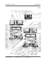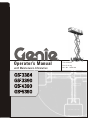
1
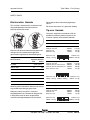
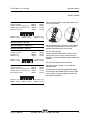
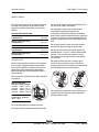
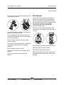
Operator’s Manual
with Maintenance Information
Third Edition
First Printing
Part No. 1000196
Operator's Manual
Third Edition • First Printing
Important
Read, understand and obey these safety rules and
operating instructions before operating this machine.
Only trained and authorized personnel shall be
permitted to operate this machine. This manual should
be considered a permanent part of your machine and
should remain with the machine at all times. If you
have any questions, please call Genie Industries.
Contents
Page
Safety ........................................................................ 1
Legend ....................................................................... 9
Controls .................................................................... 10
Pre-operation Inspection ........................................... 12
Maintenance ............................................................. 14
Function Tests .......................................................... 17
Workplace Inspection ................................................ 21
Operating Instructions ............................................... 22
Transport and Lifting Instructions .............................. 27
Decals ...................................................................... 30
Specifications ........................................................... 38
Copyright © 2002 by Genie Industries
Contact us:
Internet: http://www.genielift.com
e-mail: [email protected]
First Edition:
First Printing, January 2002
Second Edition:
Third Printing, October 2004
Third Edition:
First Printing, August 2005
"Genie" is a registered trademark of
Genie Industries in the U.S.A. and many other
countries. "GS" is a trademark of Genie
Industries.
These machines comply with
ANSI/SIA 92.6-1999.
Printed on recycled paper
Printed in U.S.A.
GS-3384 • GS-3390 • GS-4390 • GS-5390
Part No. 1000196
Third Edition • First Printing
Operator’s Manual
Safety Rules
Danger
Failure to obey the instructions and
safety rules in this manual will
result in death or serious injury.
Do Not Operate Unless:
You learn and practice the principles of safe
machine operation contained in this operator’s
manual.
1 Avoid hazardous situations.
Know and understand the safety rules before
going on to the next section.
2 Always perform a pre-operation inspection.
3 Always perform function tests prior to use.
4 Inspect the workplace.
5 Only use the machine as it was intended.
You read, understand and obey the
manufacturer’s instructions and safety rules—
safety and operator’s manuals and machine
decals.
You read, understand and obey employer’s
safety rules and worksite regulations.
You read, understand and obey all applicable
governmental regulations.
You are properly trained to safely operate the
machine.
Part No. 1000196
GS-3384 • GS-3390 • GS-4390 • GS-5390
1
Operator’s Manual
Third Edition • First Printing
SAFETY RULES
Electrocution Hazards
Do not operate the machine during lightning or
storms.
This machine is not electrically insulated and will
not provide protection from contact with or
proximity to electrical current.
Do not use the machine as a ground for welding.
Tip-over Hazards
Occupants, equipment and materials shall not
exceed the maximum platform capacity or the
maximum capacity of the platform extension.
Maximum capacity - GS-3384 and GS-3390
Maximum occupants
Maintain safe distances from electrical power lines
and apparatus in accordance with applicable
governmental regulations and the following chart.
Voltage
Phase to Phase
0 to 300V
Minimum Safe
Approach Distance
Feet
Meters
Avoid Contact
300V to 50KV
10
3.05
50KV to 200KV
15
4.60
200KV to 350KV
20
6.10
350KV to 500KV
25
7.62
500KV to 750KV
35
10.67
750KV to 1000KV
45
13.72
Allow for platform movement, electrical line sway or
sag and beware of strong or gusty winds.
Keep away from the machine if it contacts
energized power lines. Personnel on the ground or
in the platform must not touch or operate the
machine until energized power lines are shut off.
2
7
Models with one platform extension
Platform retracted
2500 lbs
Platform only
2000 lbs
Extension only
500 lbs
Extension only
500 lbs / 227 kg
Platform only
2000 lbs / 907 kg
Models with two platform extensions
Platform retracted
2500
Platform with one extension out 2000
Platform with two extensions out 1500
Each extension only
500
Extension only
Platform only
500 lbs / 227 kg 1500 lbs / 680 kg
1134 kg
907 kg
227 kg
lbs
lbs
lbs
lbs
1134
907
680
227
kg
kg
kg
kg
Extension only
500 lbs / 227 kg
Maximum capacity - GS-4390
Maximum occupants
7
Models with one platform extension
Platform retracted
1500 lbs
Platform only
1000 lbs
Extension only
500 lbs
Extension only
500 lbs / 227 kg
GS-3384 • GS-3390 • GS-4390 • GS-5390
680 kg
454 kg
227 kg
Platform only
1000 lbs / 454 kg
Part No. 1000196
Third Edition • First Printing
Operator’s Manual
SAFETY RULES
Models with two platform extensions
Platform retracted
1500
Platform with one extension out 1000
Platform with two extensions out
500
Each extension only
500
Extension only
500 lbs / 227 kg
Platform only
500 lbs / 227 kg
lbs
lbs
lbs
lbs
680
454
227
227
kg
kg
kg
kg
Do not raise the platform unless the machine is on
a firm, level surface.
Extension only
500 lbs / 227 kg
Maximum capacity - GS-5390
Maximum occupants - ANSI & CSA
6
Maximum occupants - Australia
4
Models with one platform extension
Platform retracted
1500 lbs
Platform only
1000 lbs
Extension only
500 lbs
Platform only
1000 lbs / 454 kg
Extension only
500 lbs / 227 kg
Models with two platform extensions
Platform retracted
1500
Platform with one extension out 1000
Platform with two extensions out
500
Each extension only
500
Extension only
500 lbs / 227 kg
680 kg
454 kg
227 kg
Platform only
500 lbs / 227 kg
Part No. 1000196
lbs
lbs
lbs
lbs
680
454
227
227
kg
kg
kg
kg
Do not depend on the tilt alarm as a level indicator.
The tilt alarm sounds on the chassis and in the
platform when the machine is on a slope.
If the tilt alarm sounds:
Lower the platform. Move the machine to a firm,
level surface. If the tilt alarm sounds when the
platform is raised, use extreme caution to lower the
platform.
Do not alter or disable the limit switches.
Do not drive over 0.7 mph / 1.1 km/h with the
platform raised.
Use extreme care and slow speeds while driving
the machine in the stowed position across uneven
terrain, debris, unstable or slippery surfaces and
near holes and drop-offs.
Extension only
500 lbs / 227 kg
GS-3384 • GS-3390 • GS-4390 • GS-5390
3
Operator’s Manual
Third Edition • First Printing
SAFETY RULES
Do not drive the machine on a slope that exceeds
the slope and side slope rating of the machine.
Slope rating applies to machines in the stowed
position.
GS-3384, GS-3390, GS-4390
Maximum slope rating,
stowed position
50% (26°)
Maximum side slope rating,
stowed position
50% (26°)
Do not alter or disable machine components that in
any way affect safety and stability.
Do not modify or alter an aerial work platform
without prior written permission from the
manufacturer. Mounting attachments for holding
tools or other materials onto the platform, toeboards
or guard rail system can increase the weight in the
platform and the surface area of the platform or the
load.
Do not replace items critical to machine stability
with items of different weight or specification.
GS-5390
Maximum slope rating,
stowed position
40% (22°)
Maximum side slope rating,
stowed position
40% (22°)
Note: Slope rating is subject to ground conditions and
adequate traction.
Do not use the platform controls to free a platform
that is caught, snagged or otherwise prevented
from normal motion by an adjacent structure. All
personnel must be removed from the platform
before attempting to free the platform using the
ground controls.
Do not raise the platform when wind speeds may
exceed 28 mph / 12.5 m/s. If wind speeds exceed
28 mph / 12.5 m/s when the platform is raised,
lower the platform and do not continue to operate
the machine.
Do not operate the machine in strong or gusty
winds. Do not increase the surface area of the
platform or the load. Increasing the area exposed to
the wind will decrease machine stability.
Do not push off or pull toward any object outside of
the platform.
Maximum allowable
side force - ANSI and CSA
GS-3384 350 lbs / 1557 N
GS-3390 350 lbs / 1557 N
GS-4390 350 lbs / 1557 N
GS-5390 300 lbs / 1335 N
Do not drive the machine on or near uneven terrain,
unstable surfaces or other hazardous conditions
with the platform raised.
Maximum allowable
manual force - Australia
90 lbs / 400 N
Do not tie the platform to adjacent structures.
Do not place loads outside the platform perimeter.
4
GS-3384 • GS-3390 • GS-4390 • GS-5390
Part No. 1000196
Third Edition • First Printing
Operator’s Manual
SAFETY RULES
Do not place or attach fixed or overhanging loads to
any part of this machine.
Fall Hazards
The guard rail system provides fall protection. If
occupant(s) of the platform are required to wear
personal fall protection equipment (PFPE) due to
job site or employer rules, PFPE equipment and its
use shall be in accordance with the PFPE
manufacturer’s instructions and applicable
governmental requirements.
Do not sit, stand or climb on the platform guard
rails. Maintain a firm footing on the platform floor at
all times.
Do not place ladders or scaffolds in the platform or
against any part of this machine.
Do not transport tools and materials unless they
are evenly distributed and can be safely handled by
person(s) in the platform.
Do not use the machine on a moving or mobile
surface or vehicle.
Be sure all tires are in good condition, air-filled tires
are properly inflated and lug nuts are properly
tightened.
Do not climb down from the platform when raised.
Do not use the machine as a crane.
Keep the platform floor clear of debris.
Do not push the machine or other objects with the
platform.
Close the entry gate before operating.
Do not contact adjacent structures with the
platform.
Part No. 1000196
Do not operate the machine unless the guard rails
are properly installed and the entry is secured for
operation.
GS-3384 • GS-3390 • GS-4390 • GS-5390
5
Operator’s Manual
Third Edition • First Printing
SAFETY RULES
Do not lower the platform unless the area below is
clear of personnel and obstructions.
Collision Hazards
Be aware of limited sight
distance and blind spots
when driving or operating.
Be aware of extended platform position(s) when
moving the machine.
Operators must comply with employer, job site and
governmental rules regarding use of personal
protective equipment.
Check the work area for overhead obstructions or
other possible hazards.
Limit travel speed according to the condition of the
ground surface, congestion, slope, location of
personnel, and any other factors which may cause
collision.
Bodily Injury Hazard
Always operate the machine in a well-ventilated
area to avoid carbon monoxide poisoning.
Do not operate the machine with a hydraulic oil or
air leak. An air leak or hydraulic leak can penetrate
and/or burn skin.
Be aware of crushing hazards when grasping the
platform guard rail.
Observe and use color-coded direction arrows on
the platform controls and platform decal plate for
drive and steer functions.
Improper contact with components under any cover
will cause serious injury. Only trained maintenance
personnel should access compartments. Access
by the operator is only advised when performing a
pre-operation inspection. All compartments must
remain closed and secured during operation.
Do not operate a machine in the path of any crane
or moving overhead machinery unless the controls
of the crane have been locked out and/or
precautions have been taken to prevent any
potential collision.
No stunt driving or horseplay while operating a
machine.
6
GS-3384 • GS-3390 • GS-4390 • GS-5390
Part No. 1000196
Third Edition • First Printing
Operator’s Manual
SAFETY RULES
Component Damage Hazards
Damaged Machine Hazards
Do not use any battery or charger greater than
12V DC to jump-start the engine.
Do not use a damaged or malfunctioning machine.
Explosion and Fire Hazards
Conduct a thorough pre-operation inspection of the
machine and test all functions before each work
shift. Immediately tag and remove from service a
damaged or malfunctioning machine.
Do not start the engine if you smell or detect liquid
petroleum gas (LPG), gasoline, diesel fuel or other
explosive substances.
Be sure all maintenance has been performed as
specified in this manual and the appropriate Genie
service manual.
Do not refuel the machine with the engine running.
Be sure all decals are in place and legible.
Refuel the machine and charge the battery only in
an open, well-ventilated area away from sparks,
flames and lighted tobacco.
Be sure the operator’s, safety and responsibilities
manuals are complete, legible and in the storage
container located in the platform.
Do not operate the machine in hazardous locations
or locations where potentially flammable or
explosive gases or particles may be present.
Crushing Hazards
Do not spray ether into engines equipped with glow
plugs.
Use common sense and planning when operating
the machine with the controller from the ground.
Maintain safe distances between the operator, the
machine and fixed objects.
Do not use the machine as a ground for welding.
Keep hands and limbs out of scissors.
Maintain a firm grasp on the platform rail when
removing the rail pins. Do not allow the platform
guard rails to fall.
Part No. 1000196
GS-3384 • GS-3390 • GS-4390 • GS-5390
7
Operator’s Manual
Third Edition • First Printing
SAFETY RULES
Outrigger Safety
Decal Legend
Tip-over Hazards
Genie product decals use symbols, color coding
and signal words to identify the following:
Do not lower the outriggers unless the machine is
on a firm surface. Avoid drop-offs, holes, unstable
or slippery surfaces and other possible hazardous
conditions.
When the auto level function is not being used and
the outriggers are being lowered individually, the
steer-end outriggers must be lowered first.
Do not raise the platform unless the machine is
level. Do not set the machine up on a surface
where it cannot be leveled using only the
outriggers.
Do not raise the platform unless all four outriggers
are properly lowered, the footpads are in firm
contact with the ground and the machine is level.
Do not adjust the outriggers while the platform is
raised.
Do not drive while the outriggers are lowered.
Battery Safety
Burn Hazards
Batteries contain acid. Always wear protective
clothing and eye wear when working with batteries.
Avoid spilling or contacting battery acid. Neutralize
battery acid spills with baking soda and water.
Explosion Hazard
Safety alert symbol—used to alert
personnel to potential personal
injury hazards. Obey all safety
messages that follow this symbol
to avoid possible injury or death.
Red—used to indicate the
presence of an imminently
hazardous situation which, if not
avoided, will result in death or
serious injury.
Orange—used to indicate the
presence of a potentially
hazardous situation which, if not
avoided, could result in death or
serious injury.
Yellow with safety alert symbol—
used to indicate the presence of a
potentially hazardous situation
which, if not avoided, may cause
minor or moderate injury.
Yellow without safety alert
symbol—used to indicate the
presence of a potentially
hazardous situation which, if not
avoided, may result in property
damage.
Green—used to indicate operation
or maintenance information.
Keep sparks, flames and lighted tobacco away
from batteries. Batteries emit explosive gas.
Electrocution Hazard
Avoid contact with electrical terminals.
8
GS-3384 • GS-3390 • GS-4390 • GS-5390
Part No. 1000196
Third Edition • First Printing
Operator’s Manual
Legend
1 Lanyard anchorage point
2 GFCI outlet
3 Platform controls
4 Platform entry gate
5 Platform extension lock
handle
9 Outrigger housing
(if equipped)
15 LPG tank
10 Outrigger footpad
(if equipped)
17 Non-steer tire
11 Ground controls with LCD
readout screen
6 Platform guard rails
12 Tilt alarm (behind ground
control panel)
7 Manual storage container
13 Entry ladder
8 Platform extension
14 Steer tire
Part No. 1000196
16 Fuel tank (behind cover)
18 Hydraulic tank (behind cover)
19 Power to platform (hidden
from view)
20 Safety arm (hidden from view)
GS-3384 • GS-3390 • GS-4390 • GS-5390
9
Operator’s Manual
Third Edition • First Printing
Controls
Ground Control Panel
Key switch for platform/off/ground control
selection
8
Platform up button
9
Lift function enable button
2
Engine start button
10
Backup auxiliary function enable button
3
Gasoline/LPG models: Choke button
Diesel models: Glow plug button
11
20 amp circuit breaker for controls circuit
12
Backup auxiliary down button
4
Platform down button
13
Hour meter
5
Idle select button with indicator light
14
Red Emergency Stop button
6
Gasoline/LPG models: LPG select button with
indicator light
7
LCD readout screen
1
10
GS-3384 • GS-3390 • GS-4390 • GS-5390
Part No. 1000196
Third Edition • First Printing
Operator’s Manual
CONTROLS
Platform Controls
1 Outrigger function enable
button with indicator light
2 Outrigger auto level button
3 Engine start button
4 Idle select button with
indicator light
7 Horn button
8 Generator select button with
indicator light
9 Machine on incline button
with indicator light: Low speed
operation for inclines
5 Gasoline/LPG models:
Choke button
Diesel models: Glow
plug button
10 Green power light/
Red error indicator light
6 Gasoline/LPG models:
LPG select button with
indicator light
13 Proportional control handle for
drive function
Part No. 1000196
14 Thumb rocker switch for steer
function
15 Wrist rest
16 Lift function enable button
with indicator light
17 Proportional rocker switch for
outrigger up/down and
platform up/down
11 Red Emergency Stop button
12 Function enable switch
GS-3384 • GS-3390 • GS-4390 • GS-5390
11
Operator’s Manual
Third Edition • First Printing
Pre-operation Inspection
Fundamentals
It is the responsibility of the operator to perform a
pre-operation inspection and routine maintenance.
Do Not Operate Unless:
You learn and practice the principles of safe
machine operation contained in this operator’s
manual.
1 Avoid hazardous situations.
2 Always perform a pre-operation inspection.
Know and understand the pre-operation
inspection before going on to the next
section.
3 Always perform function tests prior to use.
4 Inspect the workplace.
5 Only use the machine as it was intended.
The pre-operation inspection is a visual inspection
performed by the operator prior to each work shift.
The inspection is designed to discover if anything
is apparently wrong with a machine before the
operator performs the function tests.
The pre-operation inspection also serves to
determine if routine maintenance procedures are
required. Only routine maintenance items specified
in this manual may be performed by the operator.
Refer to the list on the next page and check each
of the items.
If damage or any unauthorized variation from
factory delivered condition is discovered, the
machine must be tagged and removed from
service.
Repairs to the machine may only be made by a
qualified service technician, according to the
manufacturer’s specifications. After repairs are
completed, the operator must perform a
pre-operation inspection again before going on to
the function tests.
Scheduled maintenance inspections shall be
performed by qualified service technicians,
according to the manufacturer’s specifications and
the requirements listed in the responsibilities
manual.
12
GS-3384 • GS-3390 • GS-4390 • GS-5390
Part No. 1000196
Third Edition • First Printing
Operator’s Manual
PRE-OPERATION INSPECTION
Pre-operation Inspection
❏ Be sure that the operator’s, safety and
responsibilities manuals are complete, legible
and in the storage container located in the
platform.
❏ Be sure that all decals are legible and in place.
See Decals section.
❏ Check for engine oil leaks and proper oil level.
Add oil if needed. See Maintenance section.
❏ Check for hydraulic oil leaks and proper oil level.
Add oil if needed. See Maintenance section.
❏ Check for engine coolant leaks and proper level
of coolant. Add coolant if needed. See
Maintenance section.
❏ Check for battery fluid leaks and proper fluid
level. Add distilled water if needed. See
Maintenance section.
Check the following components or areas for
damage, improperly installed or missing parts and
unauthorized modifications:
❏ Electrical components, wiring and electrical
cables
❏ Hydraulic hoses, fittings, cylinders and
manifolds
❏ Platform entry gate
❏ Beacon and alarms (if equipped)
❏ Safety arm
❏ Platform extension(s)
❏ Scissor pins and retaining fasteners
❏ Platform control joystick
❏ Generator (if equipped)
❏ Outrigger housings and footpads
(if equipped)
Check entire machine for:
❏ Cracks in welds or structural components
❏ Dents or damage to machine
❏ Be sure that all structural and other critical
components are present and all associated
fasteners and pins are in place and properly
tightened
❏ Side rails are installed and rail pins and bolts are
fastened
❏ Fuel and hydraulic tanks
❏ Drive motors
❏ Wear pads
❏ Tires and wheels
❏ Engine and related components
❏ Limit switches, alarms and horn
❏ Nuts, bolts and other fasteners
Part No. 1000196
GS-3384 • GS-3390 • GS-4390 • GS-5390
13
Operator’s Manual
Third Edition • First Printing
Maintenance
Check the Batteries
Observe and Obey:
Only routine maintenance items specified in this
manual shall be performed by the operator.
Scheduled maintenance inspections shall be
completed by qualified service technicians,
according to the manufacturer’s specifications
and the requirements specified in the
responsibilities manual.
Maintenance Symbols Legend
The following symbols have been
used in this manual to help
communicate the intent of the
instructions. When one or more of
the symbols appear at the
beginning of a maintenance
procedure, it conveys the meaning
below.
Indicates that tools will be required to
perform this procedure.
Proper battery condition is essential to good engine
performance and operational safety. Improper fluid
levels or damaged cables and connections can
result in engine component damage and hazardous
conditions.
Electrocution hazard. Contact with
hot or live circuits may result in
death or serious injury. Remove all
rings, watches and other jewelry.
Bodily injury hazard. Batteries
contain acid. Avoid spilling or
contacting battery acid. Neutralize
battery acid spills with baking soda
and water.
1 Put on protective clothing and eye wear.
2 Be sure that the battery cable connections are
tight and free of corrosion.
3 Be sure that the battery hold-down bars are
secure.
4 Remove the battery vent caps.
5 Check the battery acid level. If needed,
replenish with distilled water to the bottom of the
battery fill tube. Do not overfill.
6 Install the vent caps.
Indicates that new parts will be required to
perform this procedure.
Indicates that a cold engine is required
before performing this procedure.
14
GS-3384 • GS-3390 • GS-4390 • GS-5390
Part No. 1000196
Third Edition • First Printing
Operator’s Manual
MAINTENANCE
Check the Engine Oil Level
Check the Hydraulic Oil Level
Maintaining the proper engine oil level is essential
to good engine performance and service life.
Operating the machine with an improper oil level
can damage engine components.
Maintaining the hydraulic oil at the proper level is
essential to machine operation. Improper hydraulic
oil levels can damage hydraulic components. Daily
checks allow the inspector to identify changes in oil
level that might indicate the presence of hydraulic
system problems.
Check the oil level with the
engine off.
Perform this procedure with the
platform in the stowed position and
the engine off.
1 Release the latches on the engine tray and fully
slide the engine tray out.
2 Insert a 6 in / 15 cm screwdriver or rod into the
engine tray lock hole, located near the engine
tray roller wheels, to prevent the engine tray
from moving.
3 Check the oil level dipstick. Add oil as needed.
1 Visually inspect the sight gauge located on the
side of the hydraulic oil tank.
Result: The hydraulic oil level should be within
the top 2 inches / 5 cm of the sight gauge.
2 Add oil if necessary. Do not overfill.
Deutz F3L2011 Tier II Engine
Oil Type
Oil Type - cold conditions
15W-40
5W-30
Hydraulic oil specifications
Hydraulic oil type
Ford LRG-425 EFI Engine, EPA 2004 Compliant
Oil Type
Oil Type - cold conditions
Part No. 1000196
Chevron Rykon
Premium MV equivalent
10W-40
5W-30
GS-3384 • GS-3390 • GS-4390 • GS-5390
15
Operator’s Manual
Third Edition • First Printing
MAINTENANCE
Check the Engine Coolant Level
Maintaining the engine coolant at the proper level is
essential to engine service life. Improper coolant
level will affect the engine’s cooling capability and
damage engine components. Daily checks will
allow the inspector to identify changes in coolant
level that might indicate cooling system problems.
Scheduled Maintenance
Maintenance performed quarterly, annually and
every two years must be completed by a person
trained and qualified to perform maintenance on this
machine according to the procedures found in the
service manual for this machine.
Machines that have been out of service for more
than three months must receive the quarterly
inspection before they are put back into service.
1 Check the fluid level in the radiator. Add fluid as
needed.
Bodily injury hazard. Fluids in the
radiator are under pressure and
extremely hot. Use caution when
removing cap and adding fluids.
16
GS-3384 • GS-3390 • GS-4390 • GS-5390
Part No. 1000196
Third Edition • First Printing
Operator’s Manual
Function Tests
Fundamentals
The function tests are designed to discover any
malfunctions before the machine is put into service.
The operator must follow the step-by-step
instructions to test all machine functions.
Do Not Operate Unless:
You learn and practice the principles of safe
machine operation contained in this operator’s
manual.
A malfunctioning machine must never be used. If
malfunctions are discovered, the machine must be
tagged and removed from service. Repairs to the
machine may only be made by a qualified service
technician, according to the manufacturer’s
specifications.
1 Avoid hazardous situations.
2 Always perform a pre-operation inspection.
3 Always perform function tests prior to use.
After repairs are completed, the operator must
perform a pre-operation inspection and function
tests again before putting the machine into service.
Know and understand the function tests
before going on to the next section.
4 Inspect the workplace.
5 Only use the machine as it was intended.
1 Select a test area that is firm, level and free of
obstruction.
At the Ground Controls
2 Pull out the platform and ground red Emergency
Stop buttons to the on position.
3 Turn the key switch to ground control.
Result: The LCD screen will come on and
display SYSTEM READY.
Note: In cold climates, the LCD readout screen will
need to warm up before the display appears.
4 Start the engine. See Operating Instructions
section.
Test Emergency Stop
5 Push in the ground red Emergency Stop button
to the off position.
Result: The engine should turn off and no
functions should operate.
6 Pull out the red Emergency Stop button to
the on position and restart the engine.
Part No. 1000196
GS-3384 • GS-3390 • GS-4390 • GS-5390
17
Operator’s Manual
Third Edition • First Printing
FUNCTION TESTS
Test Up/Down Functions and Function Enable
At the Platform Controls
The audible warnings on this machine come from
the same central alarm. The descent alarm sounds
at 60 beeps per minute. The alarm that goes off
when the machine is not level sounds at 180 beeps
per minute.
Test Emergency Stop
7 Do not push the lift function
enable button. Push and hold
the platform up button.
Result: No function should operate.
8 Push and hold the lift function enable button.
Push and hold the platform up button.
Result: The platform should raise.
9 Push and hold the lift function enable button.
Push and hold the platform down button.
Result: The platform should lower. The descent
alarm should sound while the platform is
lowering.
Test the Auxiliary Lowering
15 Push in the platform red Emergency Stop button
to the off position.
Result: No functions should operate.
16 Pull the red Emergency Stop button out to the
on position.
Result: The green power light should come on.
Test the Horn
17 Push the horn button.
Result: The horn should sound.
Test Up/Down Functions and Function Enable
18 Start the engine.
19 Activate the up/down rocker switch in the
direction indicated by the blue arrow.
Result: The platform should not raise.
10 Push and hold the lift function enable button and
raise the platform approximately 2 feet / 60 cm.
20 Push and hold the lift function
enable button.
11 Push in the red Emergency Stop button to shut
off the engine.
21 Activate the up/down rocker
switch in the direction indicated
by the blue arrow.
12 Pull out the red Emergency Stop button to the
on position.
13 Push and hold the lift function enable button.
Push and hold the platform down button.
Result: The platform should lower.
14 Turn the key switch to platform control and
restart the engine.
18
Result: The platform should raise.
22 Push and hold the lift function enable button.
23 Activate the up/down rocker switch in the
direction indicated by the yellow arrow.
Result: The platform should lower. The descent
alarm should sound while the platform is
lowering.
GS-3384 • GS-3390 • GS-4390 • GS-5390
Part No. 1000196
Third Edition • First Printing
Operator’s Manual
FUNCTION TESTS
Test the Steering
Test Drive and Braking
Note: When performing the steer and drive function
tests, stand in the platform facing the steer end of
the machine.
27 Press and hold the function enable switch on the
control handle.
24 Press and hold the function enable switch on the
control handle.
25 Depress the thumb rocker switch on top of the
control handle in the direction identified by the
blue triangle on the control panel.
Result: The steer wheels should turn in the
direction that the blue triangle points on the
control panel.
26 Depress the thumb rocker switch in the direction
identified by the yellow triangle on the control
panel.
Result: The steer wheels should turn in the
direction that the yellow triangle points on the
control panel.
28 Slowly move the control handle in the direction
indicated by the blue arrow on the control panel
until the machine begins to move, then return
the handle to the center position.
Result: The machine should move in the
direction that the blue arrow points on the control
panel, then come to an abrupt stop.
29 Press and hold the function enable switch on the
control handle.
30 Slowly move the control handle in the direction
indicated by the yellow arrow on the control
panel until the machine begins to move, then
return the handle to the center position.
Result: The machine should move in the
direction that the yellow arrow points on the
control panel, then come to an abrupt stop.
Note: The brakes must be able to hold the machine
on any slope it is able to climb.
Test Limited Drive Speed
31 Push and hold the lift function enable button.
Raise the platform approximately 6 feet / 1.83 m
from the ground.
32 Press and hold the function enable switch on the
control handle.
33 Slowly move the control handle to the full drive
position.
Result: The maximum achievable drive speed
with the platform raised should not exceed
1.03 feet / 31 cm per second.
If the drive speed with the platform raised exceeds
1.03 feet / 31 cm per second, immediately tag and
remove the machine from service.
Part No. 1000196
GS-3384 • GS-3390 • GS-4390 • GS-5390
19
Operator’s Manual
Third Edition • First Printing
FUNCTION TESTS
Test the Up Limit Switch and the Outriggers GS-5390
34 Push and hold the lift function enable button.
Raise the platform.
Result: The platform should raise to
30 feet / 9.1 m and then stop. The platform
should not raise above 30 feet / 9.1 m unless
the outriggers are lowered.
35 Drive the machine forward.
Result: The drive function should not operate.
36 Lower the platform. If the platform is higher than
12 feet / 3.6 m from the ground, the outriggers
will not lower.
37 Push and hold the auto level
button.
38 Activate the up/down rocker switch in the down
direction.
Result: The outriggers should extend and level
the machine. A beep will sound when the
machine is level.
Test the Tilt Sensor Operation
Note: Perform this test from the ground with the
platform controller. Do not stand in the platform.
42 Fully lower the platform.
43 Drive both wheels on one side onto a
7 inch / 18 cm block.
44 Raise the platform at least 12 feet / 3.6 m.
Result: The platform should stop and the tilt
alarm will sound at 180 beeps per minute. The
indicator light on the lift function enable button
will be red.
45 Move the drive control handle in the direction
indicated by the blue arrow, then move the drive
control handle in the direction indicated by the
yellow arrow.
Result: The drive function should not work in
either direction.
46 Lower the platform and drive the machine off the
block.
Test Auxiliary Lowering
39 Raise the platform.
Result: The platform should raise to full height.
40 Lower the platform.
41 Push and hold the auto level button and raise
the outriggers.
47 Push and hold the lift function enable button and
raise the platform approximately 2 feet / 60 cm.
48 Push in the red Emergency Stop button to shut
off the engine.
49 Pull out the red Emergency Stop button to the
on position.
50 Push and hold the lift function enable button.
Activate the up/down rocker switch in the
direction indicated by the yellow arrow.
Result: The platform should lower.
20
GS-3384 • GS-3390 • GS-4390 • GS-5390
Part No. 1000196
Third Edition • First Printing
Operator’s Manual
Workplace Inspection
Workplace Inspection
Be aware of and avoid the following hazardous
situations:
·
drop-offs or holes
·
bumps, floor obstructions or debris
·
sloped surfaces
·
unstable or slippery surfaces
·
overhead obstructions and high voltage
conductors
·
hazardous locations
·
inadequate surface support to withstand all load
forces imposed by the machine
4 Inspect the workplace.
·
wind and weather conditions
Know and understand the workplace
inspection before going on to the next
section.
·
the presence of unauthorized personnel
·
other possible unsafe conditions
Do Not Operate Unless:
You learn and practice the principles of safe
machine operation contained in this operator’s
manual.
1 Avoid hazardous situations.
2 Always perform a pre-operation inspection.
3 Always perform function tests prior to use.
5 Only use the machine as it was intended.
Fundamentals
The workplace inspection helps the operator
determine if the workplace is suitable for safe
machine operation. It should be performed by the
operator prior to moving the machine to the
workplace.
It is the operator’s responsibility to read and
remember the workplace hazards, then watch for
and avoid them while moving, setting up and
operating the machine.
Part No. 1000196
GS-3384 • GS-3390 • GS-4390 • GS-5390
21
Operator’s Manual
Third Edition • First Printing
Operating Instructions
Fundamentals
The Operating Instructions section provides
instructions for each aspect of machine operation.
It is the operator’s responsibility to follow all the
safety rules and instructions in the operator’s,
safety and responsibilities manuals.
Do Not Operate Unless:
You learn and practice the principles of safe
machine operation contained in this operator’s
manual.
1 Avoid hazardous situations.
2 Always perform a pre-operation inspection.
3 Always perform function tests prior to use.
4 Inspect the workplace.
5 Only use the machine as it was intended.
22
Using the machine for anything other than lifting
personnel, along with their tools and materials, to
an aerial work site is unsafe and dangerous.
Only trained and authorized personnel should be
permitted to operate a machine. If more than one
operator is expected to use a machine at different
times in the same work shift, they must all be
qualified operators and are all expected to follow all
safety rules and instructions in the operator’s,
safety and responsibilities manuals. That means
every new operator should perform a pre-operation
inspection, function tests, and a workplace
inspection before using the machine.
GS-3384 • GS-3390 • GS-4390 • GS-5390
Part No. 1000196
Third Edition • First Printing
Operator’s Manual
OPERATING INSTRUCTIONS
Emergency Stop
Push in the red Emergency Stop button to the off
position at the ground controls or the platform
controls to stop all machine functions and turn the
engine off.
Repair any function that operates when either red
Emergency Stop button is pushed in.
Starting the Engine
1 At the ground controls, turn the key switch to
the desired position.
In cold conditions, 20°F / -6°C and below, warm the
engine for 5 minutes before operating to prevent
hydraulic system damage.
In extreme cold conditions, 0°F / -18°C and below,
machines should be equipped with optional cold
start kits. Attempting to start the engine when
temperatures are below 0°F / -18°C may require the
use of a booster battery.
Gasoline/LPG models: In cold conditions, 20°F /
-6°C and below, the machine should be started on
gasoline and warmed for 2 minutes, then switched
to LPG. Warm engines can be started on LPG.
2 Be sure both ground and platform red
Emergency Stop buttons are pulled out to the
on position.
Operation From Ground
Gasoline/LPG models
2 Pull out both ground and platform red
Emergency Stop buttons to the on position.
3 If desired, select LPG by pushing the
LPG button.
1 Turn the key switch to ground control.
3 Start the engine.
4 Push the engine start button.
To Position Platform
Diesel models
1 Push and hold the lift function
enable button.
3 Push and hold the glow plug button for 3 to
5 seconds.
4 Push the engine start button.
Drive and steer functions are not available from the
ground controls.
All models
If the engine fails to start after 15 seconds of
cranking, determine the cause and repair any
malfunction. Wait 60 seconds before trying to start
again.
Part No. 1000196
2 Activate the up function or the down
function.
Engine Idle Select
Select the engine idle (rpm) by
pressing the idle select button. There
are three settings for engine idle.
·
Indicator light off: low idle
·
Indicator light blinking: high idle activated by any
function enable button
·
Indicator light on: high idle
GS-3384 • GS-3390 • GS-4390 • GS-5390
23
Operator’s Manual
Third Edition • First Printing
OPERATING INSTRUCTIONS
Operation From Platform
1 Turn the key switch to platform control.
Drive Select Switch
Machine on incline symbol:
Low range operation for inclines
2 Pull out both ground and platform red
Emergency Stop buttons to the on position.
Indicator Light On Red
3 Start the engine.
To Position Platform
1 Push and hold the lift function enable
button.
2 Activate the up/down rocker switch in the
desired direction.
To Steer
1 Press and hold the function enable switch on the
controller.
2 Turn the steer wheels with the thumb rocker
switch located on the top of the control handle.
To Drive
1 Press and hold the function enable switch on the
controller.
2 Increase speed: Slowly move the control handle
off center.
Decrease speed: Slowly move the control
handle toward center.
Stop: Return the control handle to center or
release the function enable switch.
Use the color-coded direction arrows on the
platform controls and on the platform to identify the
direction the machine will travel.
If the indicator light is on red, push
in and pull out the red Emergency
Stop button to reset the system.
If the light stays red, tag and remove the machine
from service.
Driving on a slope
Determine the slope and side slope ratings for the
machine and determine the slope grade.
GS-3384, GS-3390, GS-4390
Maximum slope rating,
stowed position
50% (26°)
Maximum side slope rating,
stowed position
50% (26°)
GS-5390
Maximum slope rating,
stowed position
40% (22°)
Maximum side slope rating,
stowed position
40% (22°)
Note: Slope rating is subject to ground conditions
and adequate traction.
Machine travel speed is restricted when the
platform is raised.
24
GS-3384 • GS-3390 • GS-4390 • GS-5390
Part No. 1000196
Third Edition • First Printing
Operator’s Manual
OPERATING INSTRUCTIONS
To determine the slope grade:
To Extend and Retract Platform
Measure the slope with a digital inclinometer OR
use the following procedure.
1 Lift the platform extension lock handle to the
horizontal position.
You will need:
2 Push the platform extension lock handle to
extend the platform to the desired position.
carpenter’s level
straight piece of wood, at least 3 feet / 1 m long
tape measure
Do not stand on the platform extension while trying
to extend it.
3 Lower the platform extension lock handle.
Lay the piece of wood on the slope.
At the downhill end, lay the level on the top edge of
the piece of wood and lift the end until the piece of
wood is level.
While holding the piece of wood level, measure the
distance from the bottom of the piece of wood to
the ground.
Divide the tape measure distance (rise) by the
length of the piece of wood (run) and multiply
by 100.
Example:
run
Auxiliary Lowering
At the Ground Controls
Push and hold the lift function enable
button and activate the down function.
In the event of a power failure, use the
backup auxiliary lowering function.
At the Platform Controls
Push and hold the lift function enable button and
activate the up/down rocker switch in the down
direction.
Operation From Ground with
Controller
rise
Maintain safe distances between the operator, the
machine and fixed objects.
Be aware of the direction the machine will travel
when using the controller.
Run = 12 ft (144 in) / 3.6 m
Rise = 12 in / 0.3 m
12 in ÷ 144 in = 0.083 x 100 = 8.3%
0.3 m ÷ 3.6 m = 0.083 x 100 = 8.3%
If the slope exceeds the maximum slope or side
slope rating, then the machine must be winched or
transported up or down the slope. See Transport
and Lifting section.
Part No. 1000196
GS-3384 • GS-3390 • GS-4390 • GS-5390
25
Operator’s Manual
Third Edition • First Printing
OPERATING INSTRUCTIONS
Outrigger Operation
(if equipped)
Fall Protection
1 Position the machine below the desired
work area.
Note: The engine must be running for the outriggers
to operate.
2 Push and hold the auto level
button.
Personal fall protection equipment (PFPE) is not
required when operating this machine. If PFPE is
required by job site or employer rules, the following
shall apply:
All PFPE must comply with applicable
governmental regulations and must be inspected
and used in accordance with the manufacturer’s
instructions.
3 Activate the up/down rocker switch in the down
direction. The outriggers will extend and level
the machine. A beep will sound when the
machine is level.
After Each Use
The indicator light on the lift function
enable button will turn red when one
but not all outriggers are down. All
drive and lift functions are disabled.
2 Lower the platform.
The light turns green on the lift function enable
button and on the individual outrigger buttons when
all the outriggers are in firm contact with the
ground.
1 Select a safe parking location—firm level
surface, clear of obstructions and traffic.
3 Turn the key switch to the off position and
remove the key to secure from
unauthorized use.
4 Chock the wheels.
The drive function is disabled while the outriggers
are down.
To control individual outriggers
1 Push and hold one or more outrigger buttons.
2 Activate the outrigger up/down rocker switch in
the desired direction to level the machine.
26
GS-3384 • GS-3390 • GS-4390 • GS-5390
Part No. 1000196
Third Edition • First Printing
Operator’s Manual
Transport and Lifting Instructions
Free-wheel Configuration for
Winching
Chock the wheels to prevent the machine from
rolling.
Observe and Obey:
Common sense and planning must be applied to
control the movement of the machine when
lifting it with a crane or forklift.
The transport vehicle must be parked on a level
surface.
The transport vehicle must be secured to
prevent rolling while the machine is being
loaded.
Be sure the vehicle capacity, loading surfaces
and chains or straps are sufficient to withstand
the machine weight. See the serial label for the
machine weight.
2WD models: Release the non-steer wheel brakes
by turning over the torque hub disconnect caps
(see below).
4WD models: Release the wheel brakes by turning
over all four torque hub disconnect caps (see
below).
Be sure the winch line is properly secured to the
drive chassis tie points and the path is clear of all
obstructions.
Reverse the procedures described to re-engage the
brakes.
Note: The pump free-wheel valve should always
remain closed.
The machine must be on a level surface or
secured before releasing the brakes.
Disengage
Position
Do not drive the machine on a slope that
exceeds the slope or side slope rating. See
Driving on a Slope in the Operating Instructions
section.
If the slope of the transport vehicle bed exceeds
the maximum slope rating, the machine must
be loaded and unloaded using a winch as
described.
Part No. 1000196
GS-3384 • GS-3390 • GS-4390 • GS-5390
Engage
Position
27
Operator’s Manual
Third Edition • First Printing
TRANSPORT AND LIFTING INSTRUCTIONS
Securing to Truck or Trailer
for Transit
Use a minimum of four chains or straps.
Always chock the machine wheels in preparation
for transport.
Turn the key switch to the off position and remove
the key before transporting.
Retract and secure the extension deck(s).
Inspect the entire machine for loose or unsecured
items.
Use the tie-down points on the chassis for
anchoring down to the transport surface.
28
Use chains or straps of ample load capacity.
If the railings have been folded down, secure them
with straps before transporting.
GS-3384 • GS-3390 • GS-4390 • GS-5390
Part No. 1000196
Third Edition • First Printing
Operator’s Manual
TRANSPORT AND LIFTING INSTRUCTIONS
Observe and Obey:
Only qualified riggers should rig and lift the
machine.
Be sure the crane capacity, loading surfaces
and straps or lines are sufficient to withstand the
machine weight. See serial label.
Lifting Instructions
Center of gravity
X Axis
Y Axis
GS-3384
without outriggers
74.7 in
1.8 m
38.2 in
97.0 cm
GS-3384
with outriggers
75.1 in
1.9 m
37.2 in
94.5 cm
GS-3390
without outriggers
74.7 in
1.8 m
38.2 in
97.0 cm
GS-3390
with outriggers
75.1 in
1.9 m
37.2 in
94.5 cm
GS-4390
without outriggers
74.7 in
1.8 m
42.1 in
1.0 m
GS-4390
with outriggers
75.1 in
1.9 m
39.8 in
1.0 m
GS-5390
76.0 in
1.9 m
42.7 in
1.0 m
Fully lower the platform. Be sure the extension
decks, controls and covers are secure. Remove all
loose items on the machine.
Determine the center of gravity of your machine
using the table and the picture on this page.
Attach the rigging only to the designated lifting
points on the machine. There are two lifting points
on each end of the machine.
Adjust the rigging to prevent damage to the
machine and to keep the machine level.
X Axis
Y Axis
Part No. 1000196
GS-3384 • GS-3390 • GS-4390 • GS-5390
29
Operator’s Manual
Third Edition • First Printing
Decals
Inspection for Decals with Words
- GS-3384 and GS-3390
Determine whether the decals on your machine
have words or symbols. Use the appropriate
inspection to verify that all decals are legible and
in place.
Quantity
Part No.
Description
Quantity
72853
Danger - Improper Use Hazard
1
72868
Label - Engine Tray Prop
1
82210
Cosmetic - Genie GS-3384
2
82211
Notice - Max Side Force,
350 lbs / 1557 N, ANSI & CSA
2
Part No.
Description
25994
Caution - Component Damage
1
28158
Label - Unleaded
1
28159
Label - Diesel
1
82213
2
28160
Label - LPG
1
(1 additional with extra LPG tank option)
Notice - Max Capacity,
2500 lbs / 1134 kg
82215
Notice - Tire Specifications
4
28164
Notice - Hazardous Materials
1
82224
Label - HOT, Ford Tier II Engines
1
28171
Label - No Smoking
1
82366
Label - Chevron Rykon
1
28174
Label - Power to Platform, 230V
3
82417
Platform Control Panel
1
28175
Caution - Compartment Access
1
82418
Ground Control Panel
1
28176
Notice - Missing Manuals
1
82557
Label - Platform Controls Location
1
28235
Label - Power to Platform, 115V
3
82558
Warning - Skin Injection Hazard
1
28236
Warning - Failure To Read . . .
1
82559
Notice - Annual Inspection
1
31060
Danger - Do Not Alter Limit Switch
1
82561
Danger - Crushing Hazard
2
40434
Label - Lanyard Anchorage
8
82757
1
43618
Label - Directional Arrows
1
Danger - Outrigger Safety
and Instructions
43619
Label - Safety Arm
1
82793
Notice - Operating Instructions, Ground
1
43696
Danger - Electrocution Hazard
2
82798
Ground Control Panel
1
44255
Danger - Crushing Hazard
4
82809
Label - Wheel Load, GS-3384
4
44736
Danger - Tilt Alarm
1
82824
Label - Wheel Load, GS-3390
4
Notice - Deutz Engine Specs, Tier II
1
44981
Label - Air Line to Platform
2
97548
52431
Label - Ground Control Panel
1
97571
Notice - Ford LRG-425 Eng. Spec, Tier II 1
52475
Label - Transport Tie-down
4
97602
Warning - Explosion, Ether
1
52494
Caution - Crushing Hazard, Rails
1
97753
Cosmetic - Genie GS-3390
1
52967
Cosmetic - 4x4
2
97763
Notice - Max Side Force, 90 lbs / 400 N,
Australia
2
72186
Caution - Crushing Hazard
4
1000042
General Safety Rules
1
72818
Label - Test Mode Swtich
1
1000195
Notice - Operating Instructions, Platform 1
72847
Notice - Tire Specifications,
High Flotation
4
Shading indicates decal is hidden from view, i.e.
under covers
30
GS-3384 • GS-3390 • GS-4390 • GS-5390
Part No. 1000196
Third Edition • First Printing
Operator’s Manual
DECALS
40434
82210 or
97753
40434
28176 1000042 44736
52494
28236 1000195 43618
82557
82417
82757
40434
82210 or
97753
82211
or 97763
28174 or
28235
82213
44981
44255
43696
82561
28171
43619
28158 or
28159
82215 or
72847
52475
82809 or
82824
82366
25994
52967
28160
72868
82809 or
82824
82215 or
72847
52475
Hydraulic Tank
Side
40434
82213
Ground Controls
Side
82211 or
97763
44255
28175
82561
31060
43696
52431
72853
82793
72186
82215 or
72847
52475
82418
82798
82809
or 82824
97548
or 97571
Part No. 1000196
82558
82559
82809
28164
72818
72186 52475 or 82824
44981
97602 82215 82224
Serial
28174
28174
Label
or 28235 or 28235
or 72847
52967
GS-3384 • GS-3390 • GS-4390 • GS-5390
31
Operator’s Manual
Third Edition • First Printing
DECALS
Inspection for Decals with
Symbols - GS-3384 and GS-3390
Determine whether the decals on your machine
have words or symbols. Use the appropriate
inspection to verify that all decals are legible and
in place.
Part No. Description
Quantity
Part No. Description
Quantity
28158
Label - Unleaded
1
82487
Label - Read the Manual
2
28159
Label - Diesel
1
82560
Warning - Skin Injection Hazard
1
28160
Label - LPG
(1 additional with extra LPG tank option)
1
82562
Danger - Crushing Hazard
4
82798
Ground Control Panel
1
28171
Label - No Smoking
1
82808
Danger - Max Capacity, 1134 kg
2
28174
Label - Power to Platform, 230V
3
82809
Label - Wheel Load, GS-3384
4
28235
Label - Power to Platform, 115V
3
82810
Danger - Max Side Force, 1557 N, ANSI
2
40434
Label - Lanyard Anchorage
8
82812
Label - Read the Service Manual
1
43618
Label - Directional Arrows
1
82824
Label - Wheel Load, GS-3390
4
44981
Label - Air Line to Platform
2
82924
Caution - Component Damange
1
52475
Label - Transport Tie-down
4
97709
Label - HOT
1
52967
Cosmetic - 4x4
2
97719
Label - Safety Arm
1
72868
Label - Engine Tray Prop
1
97753
Cosmetic - GS-3390
1
82210
Cosmetic - Genie GS-3384
2
82417
Platform Control Panel
1
82418
Ground Control Panel
1
82473
Caution - Compartment Access
2
82474
Warning - Safety Chock
2
82475
Caution - Crushing Hazard
4
82476
Danger - Electrocution Hazard
2
Shading indicates decal is hidden from view,
i.e. under covers
32
GS-3384 • GS-3390 • GS-4390 • GS-5390
Part No. 1000196
Third Edition • First Printing
Operator’s Manual
DECALS
40434
82210
82487
40434
82417
43618
40434
82210
28174 or
28235
82810
82808
44981
82562
40434
Hydraulic Tank
Side
82476
82474
97719
82810
28171
28158
or 28159
Ground Controls
Side
82808
52475
82809
or 82824
82474
82924
82476
82562
52967
82487
28160
72868
82475
82809
or 82824
52475
82473
52475
82418
82798
97709
82475
Part No. 1000196
52475
Serial
Label
82809
or 82824
82560
52967
28174
or 28235
GS-3384 • GS-3390 • GS-4390 • GS-5390
82812
82809
or 82824
44981
33
Operator’s Manual
Third Edition • First Printing
DECALS
Inspection for Decals with Words
- GS-4390 and GS-5390
Part No.
Description
65281
Notice - Max Side Force,
2
350 lbs / 1557 N, ANSI & CSA - GS-4390
Determine whether the decals on your machine
have words or symbols. Use the appropriate
inspection to verify that all decals are legible and
in place.
72186
Caution - Crushing Hazard
72816
Notice - Max Capacity, 1500 lbs / 680 kg 2
72818
Label - Test Mode Swtich
1
72847
Notice - Tire Specifications,
High Flotation
4
1
Quantity
Quantity
4
Part No.
Description
25994
Warning - Component Damage
1
72853
Danger - Improper Use Hazard
28158
Label - Unleaded
1
72860
28159
Label - Diesel
1
Notice - Max Side Force,
2
300 lbs / 1335 N, ANSI & CSA - GS-5390
28160
Label - LPG
1
(1 additional with extra LPG tank option)
72868
Label - Engine Tray Prop
1
82224
Label - HOT, Ford Tier II Models
1
28164
Notice - Hazardous Materials
1
82366
Label - Chevron Rykon
1
28171
Label - No Smoking
1
82417
Platform Control Panel
1
28174
Label - Power to Platform, 230V
3
82418
Ground Control Panel
1
28175
Caution - Compartment Access
1
82557
Label - Platform Controls Location
1
28176
Notice - Missing Manuals
1
82558
Warning - Skin Injection Hazard
1
28235
Label - Power to Platform, 115V
3
82559
Notice - Annual Inspection
1
28236
Warning - Failure To Read . . .
1
82561
Danger - Crushing Hazard
2
31060
Danger - Do Not Alter Limit Switch
1
82757
Label - Lanyard Anchorage
8
Danger - Outrigger Safety
and Instructions
1
40434
43618
Label - Directional arrows
1
82793
Notice - Operating Instructions, Ground
1
43619
Label - Safety Arm
1
82798
Ground Control Panel
1
43696
Danger - Electrocution Hazard
2
82824
Label - Wheel Load, GS-4390
4
44255
Danger - Crushing Hazard
4
82825
Label - Wheel Load, GS-5390
4
Notice - Deutz Engine Specs, Tier II
1
44736
Danger - Tilt Alarm
1
97548
44981
Label - Air Line to Platform
2
97571
Notice - Ford LRG-425 Eng. Spec, Tier II 1
52431
Label - Ground Control Panel
1
97602
Warning - Explosion, Ether
1
52475
Label - Transport Tie-down
4
97763
Notice - Max Side Force, 90 lbs / 400 N,
Australia - GS-4390
2
52494
Caution - Crushing Hazard - Rails
1
97764
Cosmetic - 4x4
2
Notice - Max Side Force, 90 lbs / 400 N,
Australia - GS-5390
2
52967
62748
Cosmetic - Genie GS-4390
2
1000042
Danger - General Safety Rules
1
65061
Cosmetic - Genie GS-5390
2
1000195
Notice - Operating Instructions, Platform 1
65063
Notice - Tire Specifications
4
Shading indicates decal is hidden from view, i.e.
under covers
34
GS-3384 • GS-3390 • GS-4390 • GS-5390
Part No. 1000196
Third Edition • First Printing
Operator’s Manual
DECALS
40434
62748 or
65061
40434
28176 1000042 44736
52494
28236 1000195 43618
82557
82417
82757
40434
65281 or
72860 or
97763 or
97764
62748 or
65061
72816
28174 or
28235
Hydraulic Tank
Side
44981
44255
40434
65281 or
72860 or
97763 or
97764
43696
82561
28171
43619
28158
or 28159
65063
or 72847
52475
82824
or 82825
82366
25994
52967
28160
72868
82824
or 82825
65063
or 72847
52475
72816
Ground Controls
Side
44255
82561
28175
31060
43696
52431
72853
82793
72186
52475
82418
82798
65063
or 72847
52475 97548
97602
or 97571
72186
82824
or 82825
82224
Part No. 1000196
82824
or 82825
82558 44981
Serial
Label
65063
or 72847
28164
52967
GS-3384 • GS-3390 • GS-4390 • GS-5390
28174
or 28235
72818
82559
35
Operator’s Manual
Third Edition • First Printing
DECALS
Inspection for Decals with
Symbols - GS-4390 and GS-5390
Determine whether the decals on your machine
have words or symbols. Use the appropriate
inspection to verify that all decals are legible and
in place.
Part No. Description
Quantity
Part No. Description
Quantity
28158
Label - Unleaded
1
82476
Danger - Electrocution Hazard
2
28159
Label - Diesel
1
82487
Label - Read the Manual
2
28160
Label - LPG
(1 additional with extra LPG tank option)
1
82560
Warning - Skin Injection Hazard
1
82562
Danger - Crushing Hazard
4
28171
Label - No Smoking
1
82756
Label - Tire Pressure, High Flotation
4
28174
Label - Power to Platform, 230V
3
82798
Ground Control Panel
1
28235
Label - Power to Platform, 115V
3
82810
Label - Lanyard Anchorage
8
Danger - Max Side Force, 1557 N,
- GS-4390, ANSI
2
40434
43618
Label - Directional Arrows
1
82812
Label - Read the Service Manual
1
44981
Label - Air Line to Platform
2
82819
2
52475
Label - Transport Tie-down
4
Danger - Max Side Force, 1335 N,
- GS-5390, ANSI
52967
Cosmetic - 4x4
2
82820
Danger - Max Capacity, 680 kg
- GS-4390, ANSI
2
62748
Cosmetic - Genie GS-4390
2
82822
Cosmetic - Genie GS-5390
2
Danger - Max Capacity, 680 kg
- GS-5390, ANSI
2
65061
72868
Label - Engine Tray Prop
1
82824
Label - Wheel Load, GS-4390
4
82417
Platform Control Panel
1
82825
Label - Wheel Load, GS-5390
4
82418
Ground Control Panel
1
82924
Caution - Component Damage
1
82473
Caution - Compartment Access
1
97709
Label - HOT
1
82474
Warning - Safety Chock
2
97719
Label - Safety Arm
1
82475
Caution - Crushing Hazard
4
Shading indicates decal is hidden from view,
i.e. under covers
36
GS-3384 • GS-3390 • GS-4390 • GS-5390
Part No. 1000196
Third Edition • First Printing
Operator’s Manual
DECALS
40434
62748 or
65061
40434
82487
82417
43618
40434
62748 or
65061
28174 or
28235
82810
or 82819
82820
or 82822
44981
82562
40434
82820
or 82822
Hydraulic Tank
Side
40434
82476
82474
97719
28158
or 28159
82810
or 82819
Ground Controls
Side
28171
52475
82756
82824
or 82825
82474
82924
52967
82487
82562
82476
28160
72868
82756
82475
52475
82824
or 82825
82473
52475
82418
82798
82756
97709
52475
82475
Part No. 1000196
82756
28160
Serial
Label
82824
or 82825
82812
52967
GS-3384 • GS-3390 • GS-4390 • GS-5390
28174
or 28235
82560
82824
or 82825
44981
37
Operator’s Manual
Third Edition • First Printing
Specifications
Model
GS-3384
Platform dimensions
Height, working maximum
39 ft
12.1 m
Platform length x width
Height, platform maximum
33 ft
10.1 m
Platform extension length
Height, stowed maximum
Rails up
105.5 in
2.7 m
Height, stowed maximum
Rails lowered
78.75 in
2.0 m
84 in
2.1 m
Length, platform retracted
155.25 in
Models with one extension deck
3.9 m
Length, platform extended
212.5 in
Models with one extension deck
5.4 m
Maximum hydraulic pressure
(functions)
Length, platform retracted
156.5 in
Models with two extension decks
3.9 m
Tire size - standard tires
Length, platform extended
258.5 in
Models with two extension decks
6.6 m
Length, platform retracted
Models with outriggers
Models with two super decks
192 in
4.9 m
Length, platform extended
Models with two super decks
290.5 in
7.4 m
Maximum load capacity
2500 lbs
1134 kg
Floor loading information
Maximum wind speed
28 mph
12.5 m/s
Tire load, maximum
3800 lbs
1724 kg
Wheelbase
113.5 in
2.9 m
Tire contact pressure
127 psi
8.91 kg/cm2
873 kPa
234 in
5.9 m
Occupied floor pressure
160 psf
121.5 in
3.1 m
783 kg/m2
7.68 kPa
13 in
33 cm
Width, standard tires
Turning radius (outside)
Turning radius (inside)
Ground clearance
AC outlet in platform
60 in
1.5 m
4 mph
6.4 km/h
Drive speeds
Stowed, maximum
Platform raised, maximum
0.7 mph
1.1 km/h
40 ft/39 sec 12.2 m/39 sec
Airborne noise emissions
80 dB
Maximum sound level at normal operating workstations
(A-weighted)
3500 psi
241.3 bar
10-16.5 NHS
Tire size - high flotation tires
Weight
See Serial Label
(Machine weights vary with option configurations)
Controls
150 in x 72 in 3.8 m x 1.8 m
33/16LL500, 10 ply
Maximum slope rating,
stowed position
50% (26°)
Maximum side slope rating,
stowed position
50% (26°)
Note: Slope rating is subject to ground conditions and
adequate traction.
Note: Floor loading information is approximate and
does not incorporate different option configurations.
It should be used only with adequate safety factors.
Proportional
standard
Continuous improvement of our products is a Genie policy.
Product specifications are subject to change without notice or obligation.
38
GS-3384 • GS-3390 • GS-4390 • GS-5390
Part No. 1000196
Third Edition • First Printing
Operator’s Manual
SPECIFICATIONS
Model
GS-3390
Platform dimensions
Height, working maximum
39 ft
12.1 m
Platform length x width
Height, platform maximum
33 ft
10.1 m
Platform extension length
Height, stowed maximum
Rails up
1051/2 in
2.7 m
Height, stowed maximum
Rails lowered
783/4 in
2.0 m
90 in
2.3 m
Length, platform retracted
1551/4 in
Models with one extension deck
3.9 m
Length, platform extended
2121/2 in
Models with one extension deck
5.4 m
Maximum hydraulic pressure
(functions)
Length, platform retracted
1561/2 in
Models with two extension decks
3.9 m
Tire size - standard tires
Length, platform extended
2581/2 in
Models with two extension decks
6.6 m
Length, platform retracted
Models with outriggers
Models with two super decks
192 in
4.9 m
Length, platform extended
Models with two super decks
2901/2 in
7.4 m
Maximum load capacity
2500 lbs
1134 kg
Floor loading information
28 mph
12.5 m/s
Tire load, maximum
4500 lbs
2041 kg
Wheelbase
115 in
2.9 m
Tire contact pressure
125 psi
8.80 kg/cm2
862 kPa
Turning radius (outside)
210 in
5.3 m
Occupied floor pressure
151 psf
Turning radius (inside)
85 in
2.2 m
735 kg/m2
7.21 kPa
Ground clearance
14 in
36 cm
Width, standard tires
Maximum wind speed
AC outlet in platform
60 in
1.5 m
5 mph
8 km/h
0.7 mph
40 ft/39 sec
1.1 km/h
12.2 m/39 s
Drive speeds
Stowed, maximum
Platform raised, maximum
Airborne noise emissions
80 dB
Maximum sound level at normal operating workstations
(A-weighted)
3500 psi
241.3 bar
12 x 21.5
Tire size - high flotation tires
Weight
See Serial Label
(Machine weights vary with option configurations)
Controls
150 in x 72 in 3.8 m x 1.8 m
33/16LL500, 10 ply
Maximum slope rating,
stowed position
50% (26°)
Maximum side slope rating,
stowed position
50% (26°)
Note: Slope rating is subject to ground conditions and
adequate traction.
Note: Floor loading information is approximate and
does not incorporate different option configurations.
It should be used only with adequate safety factors.
Proportional
standard
Continuous improvement of our products is a Genie policy.
Product specifications are subject to change without notice or obligation.
Part No. 1000196
GS-3384 • GS-3390 • GS-4390 • GS-5390
39
Operator’s Manual
Third Edition • First Printing
SPECIFICATIONS
Model
GS-4390
Platform dimensions
Height, working maximum
49 ft
15.1 m
Platform length x width
Height, platform maximum
43 ft
13.1 m
Platform extension length
Height, stowed maximum
Rails up
115.5 in
2.9 m
Height, stowed maximum
Rails lowered
88.75 in
2.9 m
90 in
2.3 m
101 in
2.6 m
Length, platform retracted
155.25 in
Models with one extension deck
3.9 m
Length, platform extended
212.5 in
Models with one extension deck
5.4 m
Length, platform retracted
156.5 in
Models with two extension decks
3.9 m
Tire size - high flotation tires
Length, platform extended
258.5 in
Models with two extension decks
6.6 m
Maximum slope rating,
stowed position
50% (26°)
Length, platform retracted
Models with outriggers
Models with two super decks
192 in
4.9 m
Maximum side slope rating,
stowed position
50% (26°)
Length, platform extended
Models with two super decks
290.5 in
7.4 m
Maximum load capacity
1500 lbs
680 kg
28 mph
12.5 m/s
Wheelbase
115 in
2.9 m
Turning radius (outside)
210 in
5.3 m
Turning radius (inside)
85 in
2.2 m
Ground clearance
14 in
36 cm
Width, standard tires
Width, high-flotation tires
Maximum wind speed
AC outlet in platform
60 in
1.5 m
5 mph
8 km/h
Drive speeds
Stowed, maximum
Platform raised, maximum
0.7 mph
1.1 km/h
40 ft/39 sec 12.2 m/39 sec
Airborne noise emissions
80 dB
Maximum sound level at normal operating workstations
(A-weighted)
Maximum hydraulic pressure
(functions)
3500 psi
Tire size - standard tires
241.3 bar
12 x 21.5
33/16LL500, 10 ply
Note: Slope rating is subject to ground conditions and
adequate traction.
Weight
See Serial Label
(Machine weights vary with option configurations)
Controls
150 in x 72 in 3.8 m x 1.8 m
Floor loading information
Tire load, maximum
4500 lbs
2041 kg
Tire contact pressure
125 psi
8.80 kg/cm2
862 kPa
Occupied floor pressure
151 psf
735 kg/m2
7.21 kPa
Note: Floor loading information is approximate and
does not incorporate different option configurations.
It should be used only with adequate safety factors.
Proportional
standard
Continuous improvement of our products is a Genie policy.
Product specifications are subject to change without notice or obligation.
40
GS-3384 • GS-3390 • GS-4390 • GS-5390
Part No. 1000196
Third Edition • First Printing
Operator’s Manual
SPECIFICATIONS
Model
GS-5390
Platform dimensions
Height, working maximum
59 ft
18.2 m
Platform length x width
Height, platform maximum
53 ft
16.2 m
Platform extension length
Height, stowed maximum
Rails up
124 in
3.15 m
Drive speeds
Height, stowed maximum
Rails lowered
97.25 in
2.5 m
90 in
2.3 m
Width, high-flotation tires
101 in
2.6 m
Length, platform retracted
Models with one extension deck
192 in
4.9 m
150 in x 72 in 3.8 m x 1.8 m
Stowed, maximum
Width, standard tires
Platform raised, maximum
60 in
1.5 m
5 mph
8 km/h
0.7 mph
1.1 km/h
40 ft/39 sec 12.2 m/39 sec
Airborne noise emissions
80 dB
Maximum sound level at normal operating workstations
(A-weighted)
Maximum hydraulic pressure
(functions)
3500 psi
241.3 bar
Length, platform extended
23.51 in
Models with one extension deck
5.9 m
Length, platform retracted
192 in
Models with two extension decks
4.9 m
Tire size - high flotation tires
Length, platform extended
258.5 in
Models with two extension decks
6.6 m
Maximum slope rating,
stowed position
40% (22°)
Length, platform retracted
Models with outriggers
Models with two super decks
192 in
4.9 m
Maximum side slope rating,
stowed position
40% (22°)
Length, platform extended
Models with two super decks
290.5 in
7.4 m
Maximum load capacity
1500 lbs
680 kg
28 mph
12.5 m/s
Wheelbase
115 in
2.9 m
Turning radius (outside)
210 in
5.3 m
Turning radius (inside)
85 in
2.2 m
Ground clearance
14 in
36 cm
Maximum wind speed
Tire size - standard tires
AC outlet in platform
33/16LL500, 10 ply
Note: Slope rating is subject to ground conditions and
adequate traction.
Weight
See Serial Label
(Machine weights vary with option configurations)
Controls
12 x 21.5
Floor Loading Information
Tire load, maximum
5300 lbs
2404 kg
Tire contact pressure
147 psi 10.36 kg/cm2
1015 kPa
Occupied floor pressure
187 psf
912 kg/m2
8.95 kPa
Note: Floor loading information is approximate and
does not incorporate different option configurations.
It should be used only with adequate safety factors.
Proportional
standard
Continuous improvement of our products is a Genie policy.
Product specifications are subject to change without notice or obligation.
Part No. 1000196
GS-3384 • GS-3390 • GS-4390 • GS-5390
41
California Proposition 65
WARNING
The exhaust from this product contains chemicals
known to the State of California to cause cancer,
birth defects or other reproductive harm.
Phone 425.881.1800
Toll Free USA and Canada
800.536.1800
Fax 425.883.3475
Genie Australia Pty Ltd.
Phone +61 7 3375 1660
Fax +61 7 3375 1002
Genie Scandinavia
Phone +46 31 575100
Fax +46 31 579020
Genie France
Phone +33 (0)2 37 26 09 99
Fax +33 (0)2 37 26 09 98
Genie Iberica
Phone +34 93 579 5042
Fax +34 93 579 5059
Genie Germany
Phone +49 (0)4202 88520
Fax +49 (0)4202 8852-20
Genie U.K.
Phone +44 (0)1476 584333
Fax +44 (0)1476 584334
Genie Mexico City
Phone +52 55 5666 5242
Fax +52 55 5666 3241
Genie China
Phone +86 21 53852570
Fax +86 21 53852569
Genie Malaysia
Phone +65 98 480 775
Fax +65 67 533 544
Genie Japan
Phone +81 3 3453 6082
Fax +81 3 3453 6083
Genie Korea
Phone +82 25 587 267
Fax +82 25 583 910
Genie Brasil
Phone +55 11 41 665 755
Fax +55 11 41 665 754
Genie Holland
Phone +31 183 581 102
Fax +31 183 581 566
Distributed By:
Genie North America