1
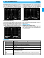
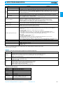
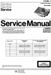
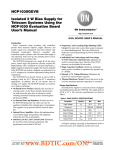
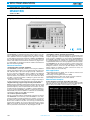
SPECTRUM ANALYZERS
SPECTRUM ANALYZER
MS2601B/K
9 kHz to 2.2 GHz
High-Speed Measurement of Various Devices
GPIB
The MS2601B/K is a wide-band spectrum analyzer which covers the
video to VHF/UHF bands. The synthesized local oscillator and automatic calibration, which uses a highly accurate signal source, enable
accurate frequency and level measurement. In addition, the MS2601B/K
has new and original functions such as the zone marker and scroll
function, that shorten measurement time. Furthermore, plug-in memory cards (PMCs) for storing measurement conditions and waveform
data offer excellent operability.
Advanced functions
• High-level built-in automatic calibration
The MS2601B/K automatically calibrates itself using the calibration
signal from the built-in signal source each time the CAL key is pressed.
The calibration data is processed at high speed by a 16-bit microprocessor and the compensation value is added to the displayed
measured value. The reliability of measurements has been greatly
improved and the measurement error has been reduced to about
one-third of conventional models, resulting in a general level measurement accuracy of 1 dB.
Furthermore, when the working temperature changes drastically, an
accurate measurement can be made just by pressing the CAL key.
• Digital technology supports high-accuracy measurement
Digital technology, including a synthesized local signal, has been used
to greatly improve the level measurement accuracy. Also, the signal
peak-level frequency can be measured with 1 Hz resolution even at a
2.2 GHz full sweep. Furthermore, in addition to having a QP detector, three resolution bandwidths, and time constants based on CISPR standards, the antenna calibration coefficients are automatically
calculated to facilitate the best EMI measurement.
• IC cards for spectrum analyzers
The age of spectrum analyzers operated by IC cards has now arrived.
The MS2601B/K uses IC memory cards called PMCs to store measurement conditions and waveform data. For example, once the test
procedures are stored in the PMCs, measurements can be made under the same conditions at any time. You can keep your hard-earned
measurement conditions as your personal know-how. Also, if these
PMCs are used with the Personal Test Automation (PTA) program
memory, automatic measurement can be packaged in a card.
164
• PTA widens realm of automatic measurements
The PTA function is a high-level language for measurement and a
computer integrated in a spectrum analyzer. Programs for measurements, operation, and display, etc. can be input to the MS2601B/K via
the keyboard or a personal computer. Thus, the spectrum analyzer can
be configured quickly into automatic test equipment. PTA supports
complicated measurements as well as preparation of final test results.
The MS2601B/K can be used as a frequency counter, power meter,
and real-time computer for measurement operations, or as ATE combining these functions, as well as a spectrum analyzer. Also, various
support software is available to enable connection to factory automation LANs (local area networks).
Main applications
• Measuring transmission
quality such as spurious emissions from
radio communication equipment
• Measuring electromagnetic interference (EMI)
• Testing high-frequency parts such as RF converters and tuners
• Measuring various devices such as filters and ICs
Measurement examples
Correct frequency count even at 2.2 GHz-span sweep
The zone markers can be aligned with the desired signal even while
observing the entire signal at full span sweep. A 2.2 GHz signal frequency can be measured at 1 Hz resolution (see below).
www.anritsu.com
For product ordering information, see pages 4-7.
SPECTRUM ANALYZERS
Overall level accuracy of ±1 dB
Reproducible high-accuracy level measurements are ensured through
internal signal calibration, initiated simply by pressing the CAL key on
the MS2601B/K (see below). In addition, there is little cumulative LOG
linearity error so that measurements of transmission characteristics
are carried out with the same high accuracy achieved by network analyzers.
Frequency axis scroll function
Sometimes the signal on the left or right of the displayed portion must
be examined in detail during a slow sweep (see below). Just press the
scroll key to move the display two divisions left or right on the screen.
This permits areas beyond the edge of the screen to be displayed
without waiting for a new sweep to display the entire waveform.
2
Zone marker easily locates signals.
This zone marker function (patent pending) has been developed to reduce
the measurement time. Simply enter zone markers around the signal
frequency and the peak value within that zone will be measured with
0.03 dB resolution and displayed, even if the exact frequency varies. This
eliminates troublesome marker adjustment to the signal peak each time
you want to read the frequency and level (see below). The frequencyadjustment capability for an oscillator under test has been increased
remarkably, and the frequency display remains visible during adjustment.
EMI measurement
In addition to providing a QP detector and three resolution bandwidths and time constants based on CISPR standards, antenna calibration coefficients are automatically calculated to facilitate easy
EMI measurement.
Application software
MX4102B Transmitter Test System Software
The MX4102B software can be used for efficient testing of mobile
transmitter equipment that uses PTA (optional). This software can be
used to measure frequency, high-order harmonic spurious components (second to fifth order harmonics), occupied bandwidths, and
the adjacent channel power.
Specifications
Model
Frequency
Measurement frequency range
MS2601B
MS2601K
9 kHz to 2.2 GHz
Frequency setting
0 to 2210 MHz (stop frequency: ≥1 kHz)
Display resolution
20 Hz
Setting mode
CENTER/SPAN, START/SPAN, START/STOP
Set frequency span (stop freq.– start freq.) to 2 digit value (10 to 98)
Frequency display accuracy
±(100 Hz + freq. span x 2% + display freq. x reference freq. accuracy)
For CENTER/SPAN or START/SPAN mode, after auto-calibration, provided that freq. span is ≥10 kHz and sweep
time is ≤100 s
Frequency span
Setting range: 1 kHz to 2200 MHz for horizontal 10 divisions, 2-digit (10 to 98) variable, and 0 Hz (fixed tuning)
1 kHz to 2000 MHz, 1-2-5 sequence at step keys
Readout accuracy: ±2% (sweep time ≤100 s)
Resolution
Resolution bandwidth: 30 Hz to 1 MHz (3 dB bandwidth), variable in 1-3 sequence, can be selected manually or
automatically coupled to frequency span
Resolution bandwidth accuracy: ±20%
Selectivity: ≤15 : 1 (ratio of 60 dB and 3 dB bandwidth)
Stability
Residual FM: ≤20 Hz p-p/0.1 s (frequency span; ≤500 kHz)
Drift: ≤300 Hz/min (frequency span; ≤500 kHz, sweep time; ≤100 s, after 1-hour warm-up at constant ambient
temperature)
Sideband noise
≤–80 dBc (at 100 Hz resolution bandwidth, 1 Hz video bandwidth, 10 kHz from signal)
Continued on next page
For product ordering information, see pages 4-7.
www.anritsu.com
165
SPECTRUM ANALYZERS
Model
MS2601B
Frequency
Reference oscillator
NORMAL
Markers
Delta
COUNT
Measurement range
Display
Frequency response (20° to 30°C)
–130 to +20 dBm
–124 to +20 dBm
Divisions:
8 divisions on vertical axis when top line is reference level and scale is 10 dB/div
10 divisions on vertical axis for other scales
LOG (referred to reference level):
0 to –70 dB (10 dB/div), 0 to –50 dB (5 dB/div), 0 to –20 dB (2 dB/div), 0 to –10 dB (1 dB/div)
LIN: 10%/div of reference level (calibrated in voltage, unit: V)
Linearity
LOG: ±0.2 dB/0 to –10 dB, ±0.3 dB/0 to –20 dB, ±0.5 dB/0 to –50 dB (resolution bandwidth of 100 Hz to
1 MHz), ±1 dB/0 to –70 dB (resolution bandwidth of 100 Hz to 100 kHz), after automatic calibration
LIN: ±3% of reference level (fullscale)
±0.5 dB (100 kHz to 1.5 GHz), ±1.5 dB (9 kHz to 2.2
±0.5 dB (100 kHz to 2.0 GHz), ±1.5 dB (9 kHz to 2.2
GHz), input ATT at 20 dB
GHz), input ATT at 20 dB
LOG: +20 to –100 dBm (setting resolution 0.1 dB),
2750 mV to 2.70 µV
LIN: 2750 mV to 87.1 µV
Accuracy
±0.3 dB (0 to –50 dBm), ±0.75 dB (+20 to –70 dBm) after automatic calibration at frequency of 50 MHz and frequency span ≤2 MHz (resolution bandwidth, video bandwidth, sweep time, and input ATT settings at AUTO)
Average noise level
Amplitude
Function: Displays received signal frequency at marker
Resolution: 1 Hz, 10 Hz, 100 Hz selectable
Accuracy: Display frequency x reference frequency accuracy ±(2 counts or 20 Hz, whichever is greater)
LOG: +20 to –100 dBm (setting resolution 0.1 dB),
2240 mV to 2.20 µV
LIN: 2240 mV to 70.8 µV
Resolution bandwidth switching deviation
±0.3 dB (after automatic calibration)
≤–120 dBm (frequency 1 MHz to 2 GHz) with 0 dB
input ATT, 300 Hz resolution bandwidth, 1 Hz video
bandwidth
≤–114 dBm (frequency 1 MHz to 2 GHz) with 0 dB
input ATT, 300 Hz resolution bandwidth, 1 Hz video
bandwidth
2nd and 3rd
harmonic distortion
≤–75 dB (frequency 5 to 800 MHz) when 0 dB input ATT and –30 dBm input level
Residual response
≤–100 dBm (frequency ≥500 kHz) when 0 dB input
ATT and 50 Ω input termination
≤–95 dBm (frequency ≥500 kHz) when 0 dB input ATT
and 75 Ω input termination
Marker
Normal: Displays the level at settable marker
Delta: Displays the difference in levels between the settable marker and the reference marker
Noise measurement: Both the power of noise per 1 Hz bandwidth (dBm/Hz, dBc/Hz), and the adjacent channel
power (dBm/ch, dBc/ch) can be measured.
Video bandwidth
1 Hz, 10 Hz, 100 Hz, 1 kHz, 10 kHz, 100 kHz, OFF (selected manually or automatically coupled to resolution bandwidth)
Level unit
dBm, dBµV, dBmV, dBµV (emf), dBµV/m
LOG/LIN switching loss
≤±1 dB (after calibration at room temperature)
Quasi-peak detection
6 dB bandwidth: 200 Hz, 9 kHz 120 kHz ±30% (at room temperature)
Time constants for quasi-peak detection
Charge-time constant: 45 ms (for 6 dB bandwidth at 200 Hz), or 1 ms (for 6 dB bandwidth at 9 kHz and 120 kHz)
Discharge-time constant: 500 ms (for 6 dB bandwidth at 200 Hz), 160 ms (for 6 dB bandwidth at 9 kHz), or
550 ms (for 6 dB bandwidth at 120 kHz)
Display time constant: 160 ms (for 6 dB bandwidth at 200 Hz and 9 kHz), or 100 ms (for 6 dB bandwidth at 120 kHz)
Display: LOG scale; 5 dB/div (10 div)
Linearity: ±1 dB (for –40 to 0 dB carrier wave signal, at room temperature)
Field strength measurement
Antenna correction coefficients for correct display and
measurement of field strengths (dBµV/m) can be selected for certain antennas. Antenna correction coefficients have been stored in memory for the following
antennas:
MP534A/651A, MP635A/666A, MP414B
The user may define and store antenna coefficients
(for one antenna) via the GPIB interface.
Any set of user-defined antenna correction can be selected for correct display and measurement of field
strengths (dBµm). The user may define and store antenna coefficients (for one antenna) via the GPIB interface.
Impedance
50 Ω, VSWR ≤1.5 (input ATT; ≥10 dB, frequency;
≥30 kHz), N-type connector
75 Ω, VSWR ≤1.5 (input ATT; ≥10 dB, frequency; 30
kHz to 2 GHz), NC-type connector
Maximum input level
+25 dBm (input ATT; ≥10 dB), DC: ±50 V
+25 dBm (input ATT; ≥10 dB), DC: ±100 V
RF input
Sweep
Function: Displays frequency at tunable marker
Display accuracy: Same as center frequency display accuracy
Function: Displays frequency difference between reference marker and tunable marker
Display accuracy: Same as frequency span display accuracy
Setting range
Reference level
Dynamic range
MS2601K
Frequency: 10 MHz
Stability
Starting characteristic: Within ±5 x 10⁻⁸(after 20-minute warm-up, referred to frequency after 1-hour warm-up)
Aging rate: Within ±2 x 10⁻⁸/day, ≤1 x 10⁻⁷/year (referred to frequency after 24-hour warm-up)
Temperature characteristic: Within ±5 x 10⁻⁸(referred to frequency at 25°C)
External reference input
Frequency: 10 MHz, Level: 2 to 5 Vp-p
Input ATT
Attenuation: 0 to 50 dB, in 10 dB steps (selected manually or automatically coupled to reference level)
Switching accuracy: ±1 dB (100 kHz to 1.5 GHz), ±2.0 dB (9 kHz to 2.2 GHz)
Sweep time
Setting range:
50 ms to 1000 s variable in 1-1.5-2-3-5-7 sequence. Range can be selected manually or automatically according to frequency span, resolution bandwidth, and video bandwidth. It can also be set from 50 ms to 1000
s (according to the most significant 2-digits) via the GPIB interface.
Accuracy: ≤±15% (for 50 ms to 100 s range) or ≤±30% (for 100 to 1000 s range) at room temperature
Trigger
FREE RUN, LINE, VIDEO, SINGLE, EXT TRIGGER
Sweep range
Normal: Sweeps entire range, Zone marker width setting range: 1 to 501 points (odd numbers)
Zone sweep: Sweeps range between zone markers, Zone marker width setting range: 25 to 501 points (odd numbers)
Continued on next page
166
www.anritsu.com
For product ordering information, see pages 4-7.
SPECTRUM ANALYZERS
CRT display
Model
MS2601B
MS2601K
CRT
Six-inch electromagnetic deflection type (green display color)
Display items
Graticule (grid), waveform data, setting conditions, menu, title
Waveform data display method
The display screen uses digital storage, 501 points of data for horizontal-axis data, and 2 display channels (A and
B): Either channel can be selected for NORMAL, AVERAGE, MAX-HOLD, or MIN-HOLD waveforms, but only channel A can be used for the CUMULATIVE and OVERWRITE mode of displaying stored data. Channels A and B can
be displayed simultaneously.
Detection method
PEAK, SAMPLE and DIP can be selected.
Direct plotting
Screen data can be hard-copied to a plotter or printer via the GPIB interface (RS-232C interface for option 02)
Plotter compatibility: HP-GL or GP-GL compatible
Printers: EPSON’s VP-870 (or compatible models), or Hewlett-Packard’s 2225
2
ALL CAL: Calibrates all LEVEL CAL 1, LEVEL CAL 2 and FREQ CAL functions
LEVEL CAL 1: Calibrates total gain deflection and log linearity
LEVEL CAL 2: Calibrates resolution bandwidth, reference level, and LOG/LIN switching deflection
FREQ CAL: Calibrates local frequency errors, and the center frequency of the resolution bandwidth
QP CAL: Calibrates the on/off switching error apparent in quasi-peak detection
Internal memory: Save/recall 6 setting conditions
PMC: Save/recall 12 (32 KB) or 48 (128 KB) setting conditions and measurement data
Automatic calibration
Function memory
External control
GPIB (IEEE488, IEC625-1, 24 pins): All functions except power switch, CRT intensity, PMC control, GPIB address,
AM/FM modulator (option 07) and direct plotting controlled.
Interface: SH1, AH1, T6, L4, SR1, RL1, PP0, DC1, DT1, C0
Auxiliary signal input and output
IF output
Frequency: 3.6 MHz, Output level: 0 dBm ±3 dB (at the reference line on the CRT), Connector: BNC-type
50 MHz output
Frequency: 50 MHz, Output level: –2 dBm ±3 dB, Connector: BNC-type
X, Y and Z outputs
X-axis output: From 0 V (left edge) to 10 ±1 V (right edge), terminated at ≥100 kΩ, BNC-connector
Y-axis output*1: From 0 V (lower edge) to 1 ±0.3 V (upper edge), terminated at ≥100 kΩ, BNC-connector
Z-axis output: TTL level (level is low while sweep is in progress), BNC-connector
Video output
Composite: 1 Vp-p ±0.3 V, BNC-connector
Separate: 8 pins, DIN-connector
Probe power supply: +5 V ±10%, +15 V ±10%, –15 V ±10% (each 110 mA max.), 4-pole connector
External trigger input: TTL level (rising edge active), BNC-connector
External reference signal input: Use 10 MHz, 2 to 5 Vp-p reference input signal (input impedance: ≥2 kΩ), BNC-connector
Power
*2Vac
Dimensions and mass
284 (W) x 177 (H) x 451 (D) mm, ≤18.5 kg (without options)
Operating temperature range
0° to 50°C
EMC*3
EN55011: 1991, Group 1, Class A
EN50082-1: 1992
+10
–15
%, 50/60 Hz, ≤145 VA (DC operation with MZ144A Battery Pack or MZ145B DC/DC Converter)
Y-axis outputs are not automatically calibrated, their amplitude specifications are not guaranteed.
*1:2: Since
one nominal line voltage between 100 and 240 V when ordering. Maximum operational voltage is 250 V.
*3: Specify
* Electromagnetic Compatibility
Options
• Option 01: PTA (with external keyboard), Option 04: PTA (without keyboard)
Display
Number of display characters: 57 characters x 25 lines (small), 48 characters x 25 lines (medium), 41 characters x 25 lines (large)
Displayable characters: Upper-case and lower-case characters, numerals, special symbols, and cursor
Character font: 7 x 11 dot matrix (small), 9 x 13 dot matrix (medium ), 10 x 13 dot matrix (large)
Graphic: 4 screens, 400 x 575 dots
Keyboard
Character keys: Upper-case and lower-case characters, numerals, and special symbols
Editing keys: DEL, INS, < , > , ,
Command keys: RUN, STEP, RETURN, RES
PTL
Program area: 200 KB
Commands: Basic commands (18 types) and GPIB statements (2 types)
Functions: Arithmetic functions, logical functions, and system functions
System subroutines: Display subroutines and GPIB subroutines
Variables: Numeric, string, and system variable
Interfaces: GPIB and I/O ports, RS-232C and I/O port (Option 02)
>
PTA-S201
<
PTA model
• Option 02: RS-232C interface
Communication mode
Start-stop, full-duplex
Baud rate
300, 600, 1200, 2400, 4800 bps
Data bit
7, 8
Parity bit
Odd, even, none
Start bit
1 bit
Stop bit
1, 1.5, 2 bits
Control items
All items except power on/off, CRT intensity, PMC
management, AM/FM modulator (Option 02), direct plotting and RS-232C parameters
Connector
DB-25P or equivalent
For product ordering information, see pages 4-7.
www.anritsu.com
167
SPECTRUM ANALYZERS
• Option 05: Following changes to specifications
Option
MS2601B option 05
Frequency measurement range
MS2601K option 05
100 Hz to 2.2 GHz
Frequency response
±0.5 dB (100 Hz to 2.0 GHz), input ATT at 20 dB, temperature range 20° to 30°C
±0.5 dB (100 Hz to 1.5 GHz), input ATT at 20 dB, temperature range 20° to 30°C
Dynamic range
Average noise level:
Following added to standard model
≤–80 dBm (1 to 10 kHz)
≤–100 dBm (10 to 100 kHz)
≤–110 dBm (100 kHz to 1 MHz)
At 0 dB input ATT, 30 Hz RBW, 1 Hz VBW
Average noise level:
Following added to standard model
≤–74 dBm (1 to 10 kHz)
≤–94 dBm (10 to 100 kHz)
≤–104 dBm (100 kHz to 1 MHz)
At 0 dB input ATT, 30 Hz RBW, 1 Hz VBW
Impedance: 50 Ω, VSWR ≤1.5
At ≥10 dB input ATT, ≥100 Hz frequency
Impedance: 75 Ω, VSWR ≤1.5
At ≥10 dB input ATT, 100 Hz to 2 GHz frequency
Amplitude
RF input
Maximum input level: +25 dBm (≥10 dB input ATT), DC ±0 V
Input ATT switching accuracy
±1.0 dB (1 kHz to 1.5 GHz), ±2.0 dB (1.5 to 2.0 GHz)
Ordering information
Please specify model/order number, name, and quantity when ordering.
Model/Order No.
MS2601B
MS2601K
J0025A
J0104
J0017
F0012
P0005
J0308
J0121
J0017
F0012
P0005
MS2601-01
MS2601-02
MS2601-04
MS2601-05
MS2601-07
MS2601-08
MS2601-09
MC3305A
MC3306A
MX4102B
P0007
P0008
MA8601A
MA8601J
MH680A1
MA8610A
MH648A
MZ144A
MZ145B
MP534A
MP651A
168
Name
Model/Order No.
Main frame
Spectrum Analyzer (RF input: 50 Ω)
Spectrum Analyzer (RF input: 75 Ω)
MS2601B standard accessories
Coaxial cord, N-P-5W • 5D-2W • N-P-5W, 1 m: 1
Coaxial cord, UG-88U • RG55/U • N-P-55U, 1 m: 1
Power cord, 2.5 m:
1
Fuse, 3.15 A:
2
Memory card, 32 KB:
1
MS2601B/K operation manual:
1
MS2601B/K service manual:
1
pc
pc
pc
pcs
pc
copy
copy
MS2601K standard accessories
Coaxial cord, BNC-P • 3C-2WS • NCP-3W, 1 m: 1
Coaxial cord, NCP-3W • 3C-2WS • NCP-3W, 1 m: 1
Power cord, 2.5 m:
1
Fuse, 3.15 A:
2
Memory card, 32 KB:
1
MS2601B/K operation manual:
1
MS2601B/K service manual:
1
pc
pc
pc
pcs
pc
copy
copy
Options
PTA (with external JIS type PTA keyboard)
RS232C interface (used in exchange for GPIB interface)
PTA (without PTA keyboard)
Frequency range: 100 Hz to 2.2 GHz (MS2601B: with
MA8601A, MS2601K: with MA8601J)
AM/FM Modulator (cannot be installed simultaneously
with Option 09)
Protector (cannot be installed simultaneously with B0025
protective front cover)
Tilt Handle (cannot be installed simultaneously with
Option 07)
Optional instruments and parts
JIS Type PTA Keyboard
ASCII Type PTA Keyboard
Transmitter Test System Software
Memory card, 128 KB
Memory card, 256 KB
DC Block Adapter (50 Ω)
DC Block Adapter (75 Ω)
Tracking Generator
Pre-amplifier (9 kHz to 2.2 GHz)
Pre-amplifier
Battery Pack
DC/DC Converter
Dipole Antenna
Dipole Antenna
BBA9106
6502
MP635A
MP666A
MB18B
MB9A
MB19A
MP414B
MP415B
MZ126A
MP612A
MP613A
MP640A
MP654A
J0063
J0395
MP526A
MP526B
MP526C
MP526D
MP526G
B0215
B0213
B0214
B0225
B0226
B0025
B0029
B0038
B0231
MP520A
MP520B
MP520C
MP520D
MP614A
MB009
MA2601B
MA2601C
KT-10
P6201
MA8611A
www.anritsu.com
Name
Biconical antenna (30 to 300 MHz, 50 Ω)
Loop antenna (10 kHz to 30 MHz, 50 Ω)
Log-periodic Antenna
Log-periodic Antenna
Pole (for MP666A)
Tripod
Tripod (with a pole, for MP635A/666A)
Loop Antenna (9 kHz to 30 MHz, 3 bands)
Rod Antenna (9 kHz to 30 MHz, 3 bands)
Band Selector (for MP414B/MP415B)
RF Fuse Holder (DC to 1000 MHz, 50 Ω)
Fuse Element (5 pcs/set, for MP612A)
Branch
Coupler
Fixed attenuator for high power measurement (10 W, DC
to 12.4 GHz, 30 dB)
Fixed attenuator for high power measurement (30 W, DC
to 9 GHz, 30 dB)
High-Pass Filter (for 60 MHz band)
High-Pass Filter (for 150 MHz band)
High-Pass Filter (for 250 MHz band)
High-Pass Filter (for 400 MHz band)
High-Pass Filter (for 27 MHz band)
Rack mount
Carrying case (with casters)
Carrying case (without casters)
Carrying bag (with casters)
Carrying bag (without casters)
Protective front cover (cannot be installed simultaneously
with option 08)
Stacking feet
Front handle kit
CRT hood
CM Directional Coupler
CM Directional Coupler
CM Directional Coupler
CM Directional Coupler
50/75 Ω Impedance Transformer
50/75 Ω Impedance Transformer
EMI Probe
EMI Probe
EMI clamp
FET probe (Tektronix product)
EMI Probe Kit (case, MA2601B, MA2601C, MA8610A, cable)
Case for MA8611A
For product ordering information, see pages 4-7.