1
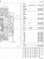
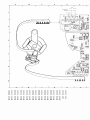
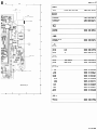
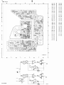
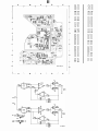
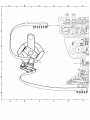
C.D.M.-1 �@ND©@ �@ND©@ Service Compact disc player MECHANISM ervice Manual reasons of production, several versions mechanism hav e been applied. For of the C.D. (illD�� The C.D. mechanisms are in most cases marked with a round, yellow sticker provided with a letter impression. The Table below indicates which exploded view and which DIGITAL AUDIO HF pre-amplifier/laser supply pca should be consulted. Exploded view drawing Sticker C,D.M. H.F. Pre-amp.+laser supply PCB +clrcult diagram A Absent A a I See Service Manual CDM-O See Service Manual CDM-O See Service Manual CDM-O See Service Manual COM-O C A 11 0 A I E See Service Manual CDM-O See Service Manual CDM-O F See Service Manual CDM-O See Service G A 11 H A 11 Manual CDM-O Salety regulations require that the set be restored to its original condition and that parts which are identical with those specilled be used. DocumentationTechnique Service Dokumentation Documentazione di Subject to modification CID 4822 725 20421 Printed in The Netherlands Servizio Huolte-Ohje Manual de Servicio Manual de Servic;ic I 5 H G 1984-10-10 J UNIT -2A A16 � 2 -1 3 Thick film unit HF 1101 +1 I. 1 4822 21810157 � 4822 209 80818 4822 209 81451 4822 209 80617 NE53 2N NE5514N �A714N -© 2 2 3 I. FOCUS ERROR BC558 B0226 4822 130 40941 53 22130 44 244 -M- A17 BZX79-C15 BAW6 2 RADIAL ERROR 3 4822130 34 281 4822130 30613 6 313 2 3138 3140 47 k 2k2 1k 48221 00 10583 4822100 20116 4822100 20115 15E MR30 56E PR37 53 22116 54914 53 22116 549 29 -DttJ;:"Y�:n+-.rr-- HF - A18 4 3165 3166 -D- © OE 47E 150E 270E 390E 4822 111 90163 2k 2 3k3 6k8 10k 1 2k 5 22k 1 20k 680k 6 31. 986 07 H J 90 217 90098 90154 90138 4822111 4822111 53 22111 4822111 53 22111 90 249 90157 90117 90 249 90097 4822111 90 251 4822111 90149 4822111 90488 -u-© 680 pF 10 nF 1101 G 4822111 53 22111 4822111 53 22111 2082 20B3 cos C03 F04 48221 2231809 48221 22317 28 1 21 3 cos 3102 F05 3133 H03 3169 3081 F04 3103 F05 3135 H03 3170 FOl 3104 3082 '-085 C 03 1.04 2086 21r,. .C04 F05 3086 2102 F05 3 87 2084 313� CO2 F05 3138 H 03 3172 3139 F02 60 1 E 6084 C 04 6085 c.o4 F03 F03 3105 3084 F03 3106 cos F03 3114 3115 cos cos .1 140 3141 C03 311� F05 3144 cm 0 F04 ]l F05 3083 3085 GO) COl E02 02 3171 8 6083 02 cos cm F03 2103 F05 3088 C03 3117 F05 3145 G02 6092 2104 EnS 3089 F03 3118 F05 3146 G02 6101 r.o5 2105 F02 3090 F04 C.o5 3149 6107 H03 2109 CO2 G02 F02 3091 H04 3150 F.02 3092 cm 3123 2)10 3124 H04 3152 2111 H04 3093 G04 3125 H04 3155 2112 G03 3094 G04 3127 H04 3156 2113 G05 3095 C.o4 H04 3160 2120 2121 F03 1122 G 02 F02 F02 G2 F02 3096 G04 3128 3129 02 3097 E03 3130 H04 31�2 FOI 30Q9 C03 3131 H03 3165 CO2 COl 3101 F05 3132 H04 316� F02 F 2122 2.124 COS H04 3161 0 �1 12 6111 COl FOI 6113 COl 6117 H04 fillfl H05 F02 CS 98 602 6 1984-10-10 1101 2101 2102 2103 A C o o 7 3 3 3 2104 2105 2109 2110 3 G 6 I 4 H10 E 2111 2112 2113 2120 F12 G12 G13 H 7 2121 2122 2123 2124 H 9 H 9 G12 H13 3101 3 1 02 3 1 03 3104 3 3 o 3 E 3 C C 3105 3106 3114 3115 3 2 E A B B 3116 3117 3118 3122 4 7 5 6 E 5 E 6 o 6 E 6 4 3123 3124 3125 3127 E 7 E 7 E 7 C 8 3128 3129 3130 3131 C o E C 3132 3133 3134 3135 8 8 8 8 o o C C 1 8 8 9 9 313 313 314 6 5 r-----------------------------------------------------• +3 I .11V i i A i C 3W6 1101 Il"d-1 AW2 C061 B GUARD I 0 r C066 A3 C I A2 � 0 D 2 r r C065 A4 r E W41 RA UNIT (X060-X0791 FoC 3WI 22k av 31 I 2WI 680p 3W2 22k av 9 W 2W2 680p 8 + FOC OFF 31 3118 I av I 0 2103 680p av 13 12 2104 680p I � 3W3 22k 3W4 22k 31 av 31 I + 3W5 -lA F 1043 LA PRE AMP + SER P.B. ASSY (XWO-XI991 3139 Q LASER OUTPUT r 2105 680P +1 2 H RAD. MOTOR L b b + C075 A115 _ C076 A 116 � ! + C077 I • ____________ _ TO SERVO pea Foe. MOTOR + TO SERVQ RAC. MOTOR pea -<1'"'=-----' L _____________________________________________________ . ALL RES. ARE CHIP RES.: ALL CAP. ARE CHIP CAP.: 2 CS 98 603 @.) b.e e FOC. MOTOR +1 3 EXCEPT 3165.3166. SUB C (XO· EXCEPT EL.CAP. 4 6 , E E 9 9 G 3 H 3 8 9 0 3141 3144 3145 3146 G 3 1 4 G 5 I 5 3149 3150 3152 3155 G 5 3156 3160 3161 3162 1 5 H 5 H 6 H 7 G 7 I 7 H B 9 8 3165 3166 3169 3170 G 9 H 9 GIO GIO 3171 3172 6101 6107 10 GI3 HI3 4 C 9 G 9 6111 H 9 6112 HIO 6113 61141-H B B 61141_1 5 fl3 6116 f l3 6117 12 11 13 14 ---------------------------------------------------------- -, i i i i� 10 r-;=�----------------------------------------------� � Hf , 1 7� 2 �� L-____________________________________________�A� r-�8 A } TO DECODER PCB 1 B i r------------------------------_J i r-------------------------, i 1 i i i ! i � --! , t +1 6 OV 13 _1 1042 X080-X099 Vc 12V A181 �,I ' i ! ', A182 -12V I 3138 c 1 L ____________________�� L ----- --- ----- ----151 I 3 D VC ¥ A184 1��} A12 ' FOCUS GAIN � , A 14l TO SERVO FOC. E RROR } PCB -----�� RAD. ERROR 1 -----�� RAD. ERROR 2 C162 +1 2111 +1 IOn ,12V 6116 BAW62 6117 BAW62 i C16l ' (+12V) +1 (,!lV) E TO SERVO PCB + fRAME + PLATE +1 TO SUPPLY pca -1 TO SUPPLY pca +3 G 2112 IOn 1-12V) -1 ---+----<F+ 8 1-12V) -lA > 4 _----_---1 6114(1/2)(B) NE532 i �i �i t-____.:.:.Al:.=.3 2=-tt(-7VJ _2A .... t-----------------------�A'-131� .. , Al42 1 r r----------------------------------------------_.J ---------- 1021 HASSIS ASSY 10-X059) i j � TO -2A SUPPLY pca TO SUPPLY pca (LASER) ON/OFf I=Off O=ON TO SERVO PCB SUPPLY 'J ,3 -1 ,J2V ,JJV -12V -lA -12V -2A -7V ... V STOP/PLAY [=:y] PLAY ONLY CJ:) STOP ONLY 36623E12 8 9 10 11 12 13 14 H A o c B TURNTABLE MOTOR ( C07 11 8 1 7 11 6 5 1 11 4 F E A12 RAD FOCUS MOTOR MOTOh J- 321 .. .. I 2 3 [CJ[e]} [[�2q 5 6 B A C 0 E 1101 C05 2086 G04 2105 E02 2113 H05 2124 G05 3090 F04 3095 G04 3102 F05 3114 G05 2082 G0 3 2101 F05 2109 G02 2120 F02 3081 F03 3086 F03 3091 G03 3096 G04 3103 F05 3115 G05 2083 G04 2102 F05 2110 E02 2121 F02 3082 F03 3087 G03 3092 G03 3097 E03 3104 F05 3116 F05 2084 2085 G03 C04 210 3 2104 F05 E05 2111 H04 G03 2122 212 3 FOI 308 3 G04 3099 3084 3089 G03 F03 309 3 C05 F03 F03 3088 2112 3094 G04 3101 G03 G05 3105 3106 G05 G05 3117 3118 F05 F05 H03 3140 G02 3169 COl 3085 F04 3122 312 3 C05 E02 3149 G02 3160 G03 6106 F05 6114 F02 H04 3129 H04 3135 H03 3141 E02 3150 F02 3161 F02 3170 GOI 6083 F03 6107 H03 6116 H04 3124 H04 3130 H04 3136 CO2 3144 G02 3152 G02 3162 GOI 3171 H02 6084 C04 6111 GOI 6117 H04 3125 H04 3131 H03 3138 H03 3145 G02 3155 F02 3165 GOI 3172 G05 6085 G04 6112 FOI 3127 H04 3132 H0 3 3139 EOI 3146 GOI 3156 F02 3166 F02 3173 H03 6092 F03 6113 GOI 3128 H04 31 3 3 6081 F 11 G 7 1984-10-10 H UNIT - 2A 1 A13 .l -1 2 3 1101 +1 I. FOCUS ERROR 2 L �} 4822 21810157 � All. 1 .------1 Thick film unit HF 4822 209 80818 4822 209 81451 4822 209 80617 NE53 2N NE5514N /LA714N RAD. ERROR 2 -© 4822130 40941 53 22130 44 244 BC558 BD226 --M3 BZX79-C 15 BAW6 2 6 313 2 3138 3140 HF-A17 4 10 :!�1l� 8 rMl 1::1 1"'1 .!-' 4822100 10583 4822100 20116 4822100 20 115 15E MR30 56E PR37 53 22116 5 4914 53 22116 5 49 29 -C}-© TO SCREENING PLATE 5 OE 4 7E 150E 270E 390E 2k2 3k3 3661.7 D12/A 6 6k8 10 k 1 2k 22k 1 20k 680 k G 47k 2k2 1k -C}3165 3166 1101 4822130 34 281 4822130 30613 H 4822111 4822111 53 22111 4822111 53 22111 90163 90 217 90098 90154 90138 4822111 4822111 53 22111 4822111 53 22111 90 249 90157 90117 90 249 90097 4822111 90 251 4822111 90149 4822111 90488 -u-© 680 pF 10 nF 48221 2231809 48221 22317 28 CS 98 604 8 1984-10-10 A B I C 0 E 1101 002 2081 C04 2082 C04 20D3 2084 2085 2086 2101 2 4 6 34 987 C7 A B 0 C E +12 6082 8C635 6083 8C636 -12 3087 lM Motor Coils )092 lM8 (A242) lie A092 56n 1089 2081 tA2") In A091 .1 +12 6084 BC6JS 6085 [A1411 IA1421 CS 98 605 � .'2 A()81 -12 2086 9C636 +12 Motor Coils IS6n � -12 3095 A082 2085 IS6n 56n 3513982 3130 3131 003 3132 E03 003 COl 003 004 2104 2105 BOI 3136 005 COS 3138 2109 005 2110 805 3140 E04 805 805 2111 E02 3141 805 2112 004 COl 3144 3139 3145 005 005 3146 COS 805 3149 COS 3150 COS 3152 COS 3081 002 C03 3082 C03 3156 3083 C04 3160 3084 C04 3161 COS COS 3085 3086 C03 3162 cos C04 3165 COS 3087 C04 3088 C03 C03 3169 006 3170 006 2120 COS 2121 2123 001 3155 3166 COS COS 805 3091 3092 C04 3171 005 C04 3172 C03 6081 002 3093 3095 C03 6082 C04 3096 C03 60R3 C04 6084 C03 804 C04 3098 C04 6085 3099 C04 6101 CO2 3101 COl 6107 004 3102 CO2 6111 006 3103 COl 6112 C06 C03 3104 802 6113 C06 3105 CO2 6116 E02 3106 001 6117 E03 CO2 CO2 3116 3117 CO2 3118 CO2 3122 6 E03 C03 C03 E03 3133 3115 5 3129 3135 3114 5 E03 C04 COl 3097 4 002 C03 D02 3090 3 002 2103 2124 3 3124 2102 2 1 13 2 3123 3127 3128 802 002 A B C II E 0 1101 2081 2082 2 3123 2085 2086 C03 C03 3125 3127 D03 E03 2101 COl 3128 E03 2102 2103 B02 3129 CO2 3130 E03 D03 2104 BOI 3131 D03 BOS 3132 E03 2109 DOS 3133 D03 D04 E04 2110 BOS 3135 2111 E03 3138 2112 D04 2113 D02 3140 BOS 2120 COS 3141 BOS 2121 2122 BOS 3144 COS COS 3145 COS 3146 COS 81 3083 36645 C12/A 6 A B c 6 E o +12 608 2 BC63S J3097 �-?C:.:J-1B Motor Coils A184 A18 3 vc i 3096 A181 � +12 .J..2086 IS6n 3 095 A182�-12 .J..208S IS6n In +12 -12 36789812 BOS D02 3149 C03 3150 COS C03 C04 3152 3155 COS COS C04 COS 3084 3085 3156 COS C03 3160 COS C04 3161 COS C04 C03 3162 3165 COS C06 8 5 D02 3139 3086 30 7 3088 5 D02 D03 802 3124 3082 t.. D02 C03 2124 t.. CO2 3122 C04 2123 3 3118 2084 30 3 31 C04 2083 2105 2 17 D02 C04 3090 C03 3166 B05 3091 C04 3169 005 3092 C04 3170 006 3093 C03 3094 D03 3171 3172 005 D02 3095 C03 3173 E04 3096 C03 6081 C04 3097 B04 6082 3098 C04 6083 C04 3099 C04 6084 C03 3101 COl 6085 C04 C03 3102 CO2 6101 CO2 3103 CO2 6107 D04 3104 6111 D06 3105 B02 CO2 6112 COS 3106 DOl 6114 COS 3113 C06 6116 E02 3114 CO2 6117 E03 3115 3116 CO2 CO2 SERVICING HINTS In order to prevent loose metal objects from getting in the CD mechanism it will be necessary to see to a clean repair station. Loosen the 4 bolts M3x18 mm until the bottom plate can be removed. Do not remove bolts M3x18 mm (they hold the new RAFOC unit together). The objective can be cleaned with a blow brush. Mount the new RAFOC unit on frame 503. Ensure that the 3 intermediate washers 502 and spring washer 505 are positioned correctly before fixing shaft item number 504. The CD-mechanism is provided with self-lubricating bearings and should thus NOT be lubricated. Ensure that ihe player Is not resting on the shaft of the turntable motor during repairs and measurements on the bottom. Servicing the RAFOC unit pos.61). (= Check that the arm moves freely and the angle setting as well (see check and possible adjustment of angle setting). For replacing the light pin it is not necessary to remove the RAFOC unit. The light pin can be removed by turning it anti clockwise by means of an open-ended spanner of 12 mm and afterwards pulling it out of the arm. During mounting, the light pin must be pushed into Radial and Focusing unit The RAFOC unit supplied by Service is the same one as in CDM-O. In the CDM-1 the bottom plate of this RAFOC unit has been replaced by frame item number 503. If the RAFOC unit is replaced, carefully an accurately perform the following operations: the arm as far as possible. and turned clockwise. Attention: To prevent adjustments from changing, NO SCREWS OTHER then those mentioned above should be loosened. Take the two flex PCBs out of the connectors on the preamplifier PCB. Disassemble the defective RAFOC unit by removing the 4 bolts M3x18 mm and shaft item number 504. THE LIGHT PIN IS MUCH MORE SENSITIVE TO STA TIC CHARGE THAN A MOS IC. CARELESS TREAT MENT DURING SERVICING MAY REDUCE LIFE EXPECTANCY DRASTICALLY. FOR THIS REASON CARE SHOULD BE TAKEN THAT DURING SER VICING THE POTENTIALS OF THE AIDS AND YOUR SELF EQUAL THE POTENTIAL OF THE MECHANISM. Remove shaft item number 504 of the new RAFOC unit. Pay attention to the 3 intermediate washers item number 502 and spring washer item number 505, they should assume the same positions after assembly. In the player chip components have been applied. For insertion and removal of chip components see Fig. MOUNTING DISMOUNTING b � VACUUM PISTON 82 SO LDERING IRON � SOLDER TIP PT ·H7 ��ci� ER 'NG SOLDER WICK 4822321 40042 A "I • 9 WELL ER A OR SOLDER 05·08mm • PRESSURE ==�nh--d""L."' SOLDER SOLDERING TIME HEATIN t �� � �� SOLDER CHIP COMPONENT -�; 05 <: 3 sec/side .,9 A PAIR OF TWEEZERS : 0 8mm B • EATIN j • PRESSURE SOLDERING IRON SOLDER COPPERTRACK SOLDER WICK C CLEANING 4 � P C,B EXAMPLES GLUE PRECAUTIONS SOLDERING IRON 0 ·,· · ,, . 0'," ,, " ., " . . .. ". " SERVICE PACKAGE SOLDERING IRON ��0$ �� � �� SOLDERING 27 012C12 CS 98 647 MECHANICAL MEASUREMENTS AND ADJUSTMENTS Height seHing of the turntable After For th i s alignment the unit should be in the position of normal end use. The servicing supports 4822 395 30202 can be used here. Playback track 1 of disc 4822 397 30096. (Disc without defects). Connect a D.C. voltmeter between the negative of the focus motor and earth of the preamplifier print. Adjust the height of the turntable with bearing screw 51 in such a way. that the voltage is 0 V +/- 100 mY. Seal hereafter the screw with sealing paint. Checking the angle� adjustment. the friction of the arm should be checked. This is done by means of a spring-pressure gauge which is connected to the counterweight. The friction of the arm. measured over the total scanning deflection. is not allowed to-exceed 30 mN. When the friction appears to be too high. the angle should be reset to its old value. Then replace the arm by a new one and check the angle once more. Adjustment of the angle is performed as follows: Place the set on the servicing supports 482239530202. 30 7(J? A�!J. Place mirror 4822 395 90205 on the objective and glass disc 4822 39590204 (with disc hold-down 482253260906) on the turntable. Locate the unit under a light source and under this light source a straight line should run (e.g. fluorescent tube with grid). Set the arm to mid-position. Turn the unit until th e arm is parallel to the line under the light source (see Fig.). Look in the direction and in the prolongation of this line . to its reflection on glass disc and mirror. These lines should not be more than 4 mm a pa rt : Position the set in such a way that one line runs across the centre of the mirror. When the other line remains inside the mirror's surface, the distance is � 4 mm. �---",--... I I I I I I I (see Fig.) until bearing plate D 11 11 11 --""'\ .� , I I _.J _--10?'Oll AI$ The arm must be kept in mid-position (see Fig.). Repeat the previous measurement. the 1' 11 11 r t .. '" . � __ J _ "i ..' J ..J angle setting With respect to the adjustment of the angle between disc and light path. the f a c t o ry has looked for a compromise between minimum angle deviation and minimum arm friction. If the measurements show that the angle falls outside the tolerance given. the angle should NOT be adjusted for minimum deviation. but just within tolerance. The new setting shou Id lie between the "old" setting and the optimum setting. be After setting the angle, t he height setting of the turntable should be checked. -- � o � __ _--- Rotate the CD mechanism through 900 relative to the previous position. can Attention ,.j (., l._ J...�- Adjusting Loosen screws C shifted. Correct the angle setting by shifting the bearing plate in the direction indicated on the Figure. Tighten screws C ensuring that the setting does not drift. Double check the angle setting in two directions. -r:;""1j ! (] t==O \ , -l2,) 30110 AIS ELECTRICAL MEASUREMENTS AND ADJUSTMENTS Motor-control check (Hall) Remove connector A09 from the motor PCS on the CDM. Laser power supply Since the light pin is very sensitive to static charges, care should be taken that during measurements and adjust ments of the laser power supply the potentia Is of aids and yourself equal the potential of the CD mechanism. +t2V +12V C5V, ______ ----< TO � A'72 2 Connect channel A of a dual-beam oscilloscope to the emitter of transistors 6082,6083 and channel S to the emitter of transistors 6084, 6085. Position of oscilloscope: 2 V/div - 10 ms/div. 3 Connect pin 1 of connector A09 on the motor PCS to the ground of the set. 4 Switch the set on. 5 Apply a negative voltage to pin 2 of connector A09. The voltage may not be applied until after the circuit has been connected to power supply voltage. Start from 0 V and slowly proceed to -5 V. Now the motor should run. When the motor runs the voltage can be brought to approx -2.5 V. The motor should continue to run then. � .- 6 +' C CL .. C-' C3 2 n_ '" C..I. (2 1 _n " -- A26 The oscilloscope should display sinus( (see Fig. A). signals now After approx 2 s they should lie symmetrically round the O-axis and be shifted 90° relative to each other. The maximum ratio of the amplitudes of these 2 signals is allowed to be 1 :2. TO A'6 C' 7 The amplitude depends on the applierJ voltage. The V-inN-out pp ratio should lie between 1:2 and.1 : 3. 8 Determine at which V-in the motor runs at 600 rpm. At 600 rpm the frequency of V-out is 30 Hz. 34 530 A'2 At this speed V-in should lie between -1.5 V and 3.7 V. Conclusion: Check The laser simulator PCS nr. 3 (4822395 30229) should be used here. Take the flex PCS out of socket A 11 and connect the switch simulator PCS with the socket. Remove plug A 16 and insert it in the socket on the simulator PCS. Connect the plug with 4 wires to socket A16. Take out plug A17 and insert the plug with 1 wire in socket A17. When all these conditions are present motor and PCS may be considered in order. If points 5, 6 and 7 are not correct, the fault should most probably be found in the electronics. If points 5, 6 and 7 are correct and the voltage to be applied at point 8 is e.g. -4.5 V to obtain a motor speed of 600 rpm, there will most probably be something wrong mechanically. E.g. the bearing friction is too high. Set the switch on the simulator PCS in the OFF position and the mains switch in the ON position. Turn trimming resistor 3140 clockwise (max. R) and measure the voltage between points +V and -V on the simulator PCS. The voltage should be � 15 mV. v Check of laser supply control: Set the switch on the simulator PCS in the ON position and measure the voltages between points +v and -v on the simulator PCS. Resistor 3140 clockwise (max. R): U +v -v = 225 mV ± 45 mV. Resistor 3140 counterclockwise (min. R): U +v -v = 750 mV ± 150 mV. Set resistor 3140 in mid-position. This is a preliminary adjustment. After the simulator PCS has been removed the laser current must be adjusted. (see service manual CD player). Adjusting the focus bandwidth (see service manual CD player). Checking the AGC and offset circuit (see service manual CD player). v 35 181 A 20 Fig. A ELECTRICAL MEASUREMENTS AND ADJUSTMENTS Laser power supply Since the light pin is very sensitive to static charges, care should be taken that during measurements and adjust ments of the laser power supply the potentia Is of aids and yourself equal the potential of the CD mechanism. +1V 2 +1V 2 CV 5 1 11 3 1984-10-10 Motor-control check (Hall) 1. Desolder the wire from point C152 on the preamplifier printed panel on the C.D.M. 2. Connect channel A of a dual-beam oscilloscope to the emitter of transistors 6082, 6083 and channel S to the emitter of transistors 6084, 6085. Position of oscilloscope: 2 V/div - 10 ms/div. 3. Switch the set on. 4. Apply a negative voltage to the wire desoldered. The voltage may not be applied until after the circuit has been connected to power supply voltage. Start from 0 V .----+--< TO A142 and slowly proceed to -5 V. Now the motor should run. When the motor runs the voltage can be brought to approx. -2.5 V. The motor should continue to run then. 5. The oscilloscope should display sinusoid signals now (see Fig. A). After approx. 2 s they should lie symmetrically round the O-axis and be shifted 90° relative to each other. The maximum ratio of the amplitude of these 2 signals is allowed to be 1:2. �: A26 2 m" C+1 (4 .......>--_... C __-_ 1 -« 3 C --= ..=--<C2 _... .. r==__-- 2 1 . .... >-1 >-.. -... TO A13 36785 Check 6. The amplitude depends on the applied voltage. The V-inlV-out pp ratio should lie between 1:2 and 1:3. 7. Determine at which V-in the motor runs at 600 rpm. At 600 rpm the frequency of V-out is 30 Hz. At this speed V-in should lie between -1.5 V and 3.7 V. Conclusion: When all these conditions are present motor and PCS may be considered in order. If pOints 4, 5 and 6 are not correct, the fault should most probably be found in the electronics. If points 4,5 and 6 are correct and the voltage to be applied at point 7 is e.g. -4.5 V to obtain a motor speed of 60 rpm, there will most probably be something wrong mecha nically. E.g. the bearing friction is too high. The laser simulator PCS nr. 4 (4822 395 30244) should be used here. Take the flex PCS out of socket A11 and connect the switch simulator PCS with the socket. Remove plug A13 and insert it in the socket on the simulator PCS. Connect the plug with 4 wires to socket A13. Take out plug A14 and insert the plug with 1 wire in socket A14. Set the switch on the simulator PCS in the OFF position and the mains switch in the ON position. Turn trimming resistor 3140 clockwise (max. R) and mea sure the voltage between pOints +V and -V on the simula tor PCS. The voltage should be � 15 mV. v Check of laser supply control Set the switch on the simulator PCS in the ON position and measure the voltages between points +v and -v on the simulator PCS. Resistor 3140 clockwise (max. R): U +v -v = 225 mV ± 45 mV. R3140 counterclockwise (min. R): U +v -v = 750 mV ±150 mV. Set resistor 3140 in the mid-position. This is a preliminary adjustment. After the simulator PCS has been removed the laser current must be adjusted. (See Service Manual CD player). Adjusting the focus bandwidth (See Service Manual CD player). Checking the AGC and offset circuit (See Service Manual CD player). v 35181 A 20 Fig. A CS 98 649 4 1984-10-10 1101 2101 2102 2103 eA o o F12 2122 2104 GE 36 2112 G12 I 7 3 3 3 2111 2105 2109 2110 4 HID 2121 2113 2120 G13 H 7 2123 2124 2 e 3103 eoE 3101 3102 H 9 H 9 G12 H13 3104 3 3 3 3 3 3105 3106 311.4 3115 4 E E 8AB 5 3118 oEE 4 7 3116 3117 6 3122 5 6 6 6 3123 3124 3125 3127 E Ee 8 E 7 7 7 3128 3129 3130 3131 6 eo 88 eE 88 3132 3133 3134 3135 oeo 88 e 9 9 J 3 313. 313' 314 7 r·_·_·_·_·_·_·_·_·_·_·_·_·_·_·_·_·_·_·_·_·_·_·_·_·_·_·. " � � mrl , , A i 1O� -r����irA� r__ __ B c C061 GUARD A3 ��� i i i 3101 0 �6����� ' ¥� I 22k�+-�--���� 31: , 2101 i r680p /f;'- C064 i' 3102 OV 9 0"V 22k��----���� + >- -f8"-:-OV A2 10 2102 � r680p 3103 1 OV 1--H1---1r---"--..::.:.:'-"Q--:�=-�_i 22k I-�--+--''-'---'''t--t __ It 3li ....>. ______--j�--------t_____i It ______ o E 3118 It >--f''''---_---+----_--1--+---�--1 2104 680p r 1041 RAFOC (X060 -XUNIT 079l Foel OFF! 31: 31, It F 3139 G LASER OUTPUT 1043 PRE AMP(Xl00-X199J +LA5ER P.B. A55Y +1 +1 QD � 2 H RAD. MOTOR FOC. MOTOR b.e b e + _ + C075 C076 TO SERVO peB Foe. MOTOR TO peB RAD. MOTOR SERVO + CS 98 601 +: -2' -7V ��___� L._._._._._._._._._._._._._._._._._._._._.....:...._._._._._._ ALL RES. ARE CHIP RES.: EXCEPT 3165.3166. ALL CAP. ARE CHIP CAP.: EXCEPT EL.CAP. 2 +1 A115 A116 C077 ,' L._._._._._._. b ! 2105 680P r 3 SUB(X041 CH 8 EE 9 9 G 3 H 3 3144 8 4 3141 G 3 3145 3146 G 5 1 5 1 3149 3150 3152 3155 G 5 1 5 H 5 H 6 3156 3160 3161 3162 9 H 7 G 7 1 7 H 8 3165 3166 3169 3170 G 9 H 9 GIO GIO 3171 3172 6101 6107 GI3 HI3 6111 G 9 6112 H 9 6113 HIO 61141-H BC 4 8 9 12 11 10 6114( -I 6116 6117 5 FI3 FI3 13 14 -._._._._._._._---_._._._._._._._-_._-_._---_._._._._.-'-' -' i i i A AI81 ! � ID HF �T=--------------------------------------------��� r-T8� �AI��2� � , 1 ____________________________________________ r .. i , 1 3 i 'L TO E O S RV c pca A09 i � 1 ! Vc 1 BX -I �AI42� A082 1 e082 -12Vi � L B i ix�8��:09�-'�'-----'---'�; -EtO, !1 1 +1 ��e081 i TO DECODER pca J ·_·_·_·_·_-_·_-----_·_·_·_·_--- i i i +12V'i -I } o I • � ._._._._._________._._._. ,_,_,_,_,_,_,___,___ ,_,_,_,_,_" i -'-'i "'7"-l1 �... Foe. ERROR �'I TO i �A� � � RAO. ERROR I �A� �3� � RAO. ERROR 2 Cl51 .,!, FRAME 2111 7 ' IOn 6116 BAW62 611 BAW62 Cl52'1 .,!, PLATE (+12Vl+1 ..._-----'F'-+ +1 (+llVl +3 2112 IOn t-'-�'--- _ ____________________ SERVO pca ____________________________________________________________________ ____________________________________________________________________ I, +1 +1 TO SUPPLY pca l +12V I =-::----F:=.;_ -I TO ... H2Vl -1 ...---....---------------= (-12Vl -lA ...-----�--! i i +-"A"' :.=2.... � � TO i ....A::: ...:.; to(-7Vl -2A .....t--� -2A TO A1� 72rl L TO � SERVO SUPPLY pca 4 6114Cl/2)(B) NE532 SUPPLY pca ______ (LASER) ON/OFF I-OFF O-ON SUPPLY pca ________________ ____ • -------------------------------------------------------------------- , 1021 ASSIS ASSY l-X059l --_._._._- 8 i j ._._._._._._._. _____________._._._._._._._._._. SUPPLY +12V +llV 12V -lA -12V -2A -7V +1 +3 -I 9 ...V ..J pca STOP/PLAY ONLY ONLY c:YJ PLAY c;}[) STOP 10 35184E 21 11 12 13 14 Q H A B C 0 E F A12 FOCUS MOTOR 1 t.. I 11 1 1 8 2 7 6 .°71 11 5 4 � .. 3 21 3 4 5 6 3 4 A B c o E F 5 6