1
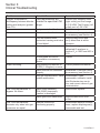
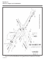
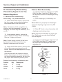
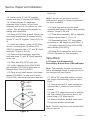
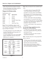
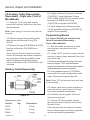
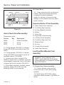
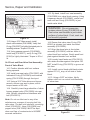
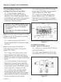
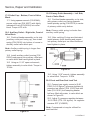
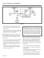
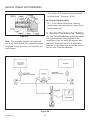
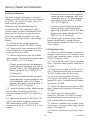
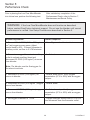
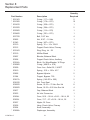
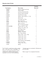
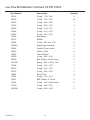
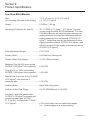
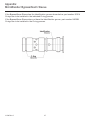
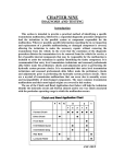
Low Flow
MicroBlender
Service Manual
L1130 Rev. C
This document is protected by United States and International Copyright laws.
This document may not be copied, reproduced, translated, stored in a retrieval system,
transmitted in any form, or reduced to any electronic medium or machine-readable form, in
whole or in part, without the written permission of CareFusion. Information in this document is
subject to change without notice.
This document is for informational purposes only and should not be considered as replacing or
supplementing the terms and conditions of the License Agreement.
© 1991 - 2013 CareFusion Corporation or one of its subsidiaries. All rights reserved.
CareFusion and the CareFusion logo are trademarks of CareFusion Corporation or one of its
subsidiaries. All other trademarks are the property of their respective owners.
CareFusion
22745 Savi Ranch Parkway
Yorba Linda, CA 92887
U.S.A.
CareFusion Germany 234 GmbH
Leibnizstrasse 7
97204 Hoechberg
Germany
800.231.2466 toll-free
714.283.2228 tel
714.283.8493 fax
+49 931 4972-0 tel
+49 931 4972-423 fax
Document part number: L1130 Revision C
ii
L1130 Rev. C
How to get help:
If you need assistance while servicing or operating the ventilator, or you require additional
information, contact CareFusion.
Technical support:
Hours: 6:00 a.m. to 5:00 p.m. PST, Monday through Friday
714.283.2228 (follow the prompts to technical support)
714.283.8471 fax
[email protected]
CareFusion helpline:
Hours: 24 hours, 7 days per week
800.231.2466 or 800.328.4139
L1130 Rev. C
iii
Table of Contents
Section 1: Overview of the 3920 Low Flow MicroBlender Operation. . 1
Section 2: Warnings, Cautions and Notes. . . . . . . . . . . . . . . . . . . . . . 4
Section 3: Troubleshooting. . . . . . . . . . . . . . . . . . . . . . . . . . . . . . . . . . 6
Section 4: Service, Repair and Calibration. . . . . . . . . . . . . . . . . . . . . . 7
Section 5: Performance Check. . . . . . . . . . . . . . . . . . . . . . . . . . . . . . 28
Section 6: Cleaning and Sterilization. . . . . . . . . . . . . . . . . . . . . . . . . 29
Section 7: Maintenance and Service Policy. . . . . . . . . . . . . . . . . . . . 30
Section 8: Replacement Parts. . . . . . . . . . . . . . . . . . . . . . . . . . . . . . 31
Section 9: Product Specifications. . . . . . . . . . . . . . . . . . . . . . . . . . . . 34
Section 10: Warranty . . . . . . . . . . . . . . . . . . . . . . . . . . . . . . . . . . . . . . 36
Appendix - MicroBlender Bypass/Alarm Sleeve . . . . . . . . . . . . . . . . . . 37
Note: This manual is intended as a guide for the service/repair calibration
of the Low Flow MicroBlender by a qualified technician.
iv
L1130 Rev. C
Section 1:
Overview of the 3920 Low Flow Microblender Operation
Balance Module (Figure 3)
The Low Flow MicroBlender mixes medical
grade compressed air and oxygen to provide
a pressurized gas source ranging from 21% to
100% oxygen.
The two gases then enter the two-stage
Balance Module. The purpose of this module
is to equalize the operating pressure of the
air and oxygen gas sources before entering
the Proportioning Module. The diaphragm
responds to the difference in pressure and
directs the movement (stroke) of each ball
valve assembly contained within the air and
oxygen chambers. The movement of each
ball valve adjusts the amount of gas flowing
through the Balance Module, equalizing the
air and oxygen pressures.
Figure 1
The two 50±5 PSIG (3.52 ± 0.35 kg/cm2) gas
sources enter through the diameter indexed
(DISS) air and oxygen inlet connectors
located on the bottom, rear of the blender
(Figure 2). Each inlet connector incorporates
a 30 micron particulate filter. From the filter
the gases travel through a duckbill check
valve which prevents possible reverse gas
flow from either the air or oxygen supply
systems.
Figure 3 Air-Oxygen Blender Diagram
Proportioning Module (Figure 4)
From the Balance Module the gases flow
into the Proportioning Module and are mixed
according to the oxygen percentage selected
on the external control knob. This Module
consists of a double ended valve positioned
between two valve seats.
Figure 2
L1130 Rev. C
1
Overview of the 3920 Low Flow MicroBlender Operation
One valve seat controls the passage of air
and the other valve seat controls the passage
of oxygen into the Low Flow MicroBlender
outlet. At this point, the two gases have been
blended according to the oxygen percentage
selected on the MicroBlender control knob.
both gas pressures (oxygen or medical air)
increase or decrease simultaneously, and
a 20 PSI (1.41 kg/cm 2) differential is not
seen, there will not be an audible alarm. If
either source gas pressure drops, the output
pressure of the blender will drop similarly,
since the source gases are always balanced
to that of the lower pressure.
The bypass function operates in unison
with the alarm. The alarm bypass poppet
communicates directly with the air supply on
one end and the oxygen supply on the other.
Figure 4
With the control knob at the full counterclockwise position (21%), the double ended
valve will completely close off the flow of
oxygen, allowing only the air to flow. By
adjusting the control knob in the full clockwise (100%) position the flow of air is
blocked, permitting only the flow of oxygen
through the blender outlet.
Figure 5
When the two source gases are near equal
in pressure, the alarm bypass poppet is
positioned over the bypass channel, blocking
the flow of both gases. The poppet will
remain seated for unequal pressures up to
20 PSI (1.41kg/cm 2). Once a 20 PSI (1.41kg/
cm 2) difference is sensed by the poppet, the
higher gas pressure will overcome the spring
force and pressure as its opposite end, thus
creating a path for gas (air or oxygen) to flow
into the alarm channel.
Alarm/Bypass (Figure 5)
The alarm feature provides for an audible
alarm if source pressures differ by 20 PSI
(1.41 kg/cm 2) or more. The primary purpose
of the alarm is to audibly warn the operator
of an excessive pressure drop or depletion of
either source gas. The alarm will also activate
in the event of elevation of either source gas
when a difference of 20 PSI
(1.41 kg/cm 2) or more is detected. Should
2
L1130 Rev. C
Overview of the 3920 Low Flow MicroBlender Operation
The gas with the higher pressure will also flow
directly to the blender outlet port bypassing the
Balance and Proportioning Modules. The gas
is also directed to the bottom of the unit to the
reed alarm, thus creating an audible warning.
The oxygen concentration will be that of the gas
at the higher pressure. The blender in the alarm/
bypass mode will deliver the oxygen (100%) or air
(21%) until the bypass mechanism resets when
source gas pressure is restored to a differential of
approximately 6 PSI (0.42 kg/cm2).
allowing the mixed gases to flow through the
primary outlet.
Some characteristics of the alarm/bypass
system on the Low Flow MicroBlender differ
somewhat from those of model 3300 and
other older model blenders.
If the Low Flow MicroBlender is set at 21%
and the oxygen source pressure is reduced
sufficiently to produce a 20 PSI (1.41kg/
cm 2) or greater differential, the unit will not
alarm because it will continue to deliver 21%
concentration according to the setting. If the
control is moved slightly from the 21% setting,
the alarm will sound.
Figure 6
The auxiliary outlet is located on the right side
of the Low Flow MicroBlender and is designed
to deliver metered gas through a flowmeter.
Mixed gas may be delivered within specified
accuracy tolerance from this outlet at 0.5
LPM and above. When a connection is made
to the auxiliary outlet a 2.5-3.5 LPM bleed
of mixed gas to the atmosphere is activated.
This bleed is essential to ensure accuracy
of concentration for applications utilizing low
flows down to 3 LPM.
Similarly, if the Low Flow MicroBlender is set
to deliver 100% concentration and air source
pressure is reduced or lost, the unit will not
alarm because it will continue to deliver the
selected 100% concentration.
The Low Flow MicroBlender is left connected
to source gases but is not being used (i.e.
no output flow or bleed flow), the unit will
not alarm if a 20 PSI (1.41kg/cm 2) or greater
pressure differential develops. It is felt that
if the blender is not in use, an alarm under
these conditions may be an unnecessary
distraction or nuisance.
Primary
outlet port
Auxiliary
outlet port
Gas Outlets (Figure 6)
The primary gas outlet is used for unmetered
high flow applications in the range of 3-30 LPM.
The flow of gas is automatically initiated by an
attachment of a pneumatic device to the outlet
port. A check valve is unseated upon connection
L1130 Rev. C
Figure 7
3
Section 2:
Warnings, Cautions and Notes
The Low Flow MicroBlender should be
operated by trained, qualified medical
personnel under the direct supervision of a
licensed physician. Before clinical application,
the WARNINGS, CAUTIONS and NOTES
should be read and understood.
CAUTION: Conditions may exist
that could damage the Low Flow
MicroBlender or other pieces of
equipment.
WARNING: Conditions may exist
NOTE: A specific point is made to assist the
operator in its understanding.
that could adversely affect the operator
or patient.
WARNINGS:
• The Low Flow MicroBlender should
be serviced and/or calibrated by a
CareFusion trained hospital/dealer
service technician or CareFusion.
• Respirable (medical) air should meet
the requirements of an ANSI Z86.11973 commodity specification for air,
Type 1 Grade D or better. It should also
have a dew point of 5°F (2.75°C) or
more below the lowest temperatures
to which the air distribution (piping)
system is exposed. Particulate
(condensed) water in the air supply
is harmful to many medical devices
utilizing or controlling compressed
air. Filters frequently become
restricted by deposits of dissolved
salts and other airborne matter. While
compressed air is typically the major
source of deposits, other medical
gases and distribution systems are
capable of delivering filter restricting
matter. This restriction of filters
causes insidious reduction in flow
capability of the blender, possibly
starving a downstream device such
as a ventilator, causing malfunction.
Therefore, it is very important to
perform preventative maintenance,
minimally at recommended intervals on
devices with filters, especially if the gas
supply is not known to be clean and/or
free of condensed water.
• The Low Flow MicroBlender is designed
to operate from a 50 PSIG (3.52 kg/
cm2) air source and a 50 PSIG (3.52
kg/cm2) oxygen source.
• Do not occlude or obstruct the bleed
port or muffler on the bottom of the
MicroBlender.
• Adjustment of oxygen concentrations
should be verified by an oxygen
analyzer.
• When the Low Flow MicroBlender is
not in use and the auxiliary outlet is
connected, close off gas supply sources
as the continuous gas bleed may drain
compressed gas tanks empty.
• When reassembling the blender, do not
pressurize the system unless the valve
seat has 3 full turns of thread engaged.
The seat can be forcefully ejected by
gas pressure if not sufficiently engaged.
Do not exceed 3 full turns or the rear
seat may be damaged.
4
L1130 Rev. C
Warnings, Cautions and Notes
Cautions:
• An air inlet filter/water trap (P/N 07426) is recommended for use with the MicroBlender
to minimize the possibility of contaminants such as particulate debris or condensed
water entering the blender or patient gas delivery system.
• Do not steam autoclave or otherwise subject the Low Flow MicroBlender to
temperatures above 145°F (62°C).
• Do not immerse assembled blender in liquid decontamination agents.
• When pressurizing the blender inlets, avoid excessive pressure surges (as could be
caused by “Quick Dump” valves). Always use needle valves and pressurize inlets slowly.
• Use recommended lubricants sparingly as lubricant may migrate to other areas and
cause the Low Flow MicroBlender to malfunction.
Notes:
• Users are advised to use pressure
regulators that display regulated
pressure.
• Allow equilibration time for FIO 2
changes before analyzing gas.
L1130 Rev. C
5
Section 3:
Clinical Troubleshooting
Problem
Oxygen concentration
discrepancy between blender
setting and analyzer (greater
than 3%).
Potential Cause
Flow requirements are
outside the specified LPM
range.
Analyzer out of calibration.
Blender out of calibration.
Low flow bleed muffler
obstructed causing restriction
of fixed bleed.
Gas supply contaminated.
Alarm sounding.
Low Flow MicroBlender in
bypass. No Alarm.
Low Flow MicroBlender
accurate only when inlet gas
pressures are equal.
Air entrained into circuit
by ventilator or accessory
device.
Inlet pressure differences of
20 PSI (1.41kg/cm 2) or more.
Alarm module not calibrated
properly.
Inlet gas contamination, alarm
module malfunction.
Alarm Reed Assembly
(P/N 05436) improperly
installed or damaged.
Alarm gas orifice obstructed.
Balance module not
functioning properly.
6
Corrective Action
Correct flow. Auxiliary outlet
(right outlet) port flow range
is 0-30 LPM. The Primary (left
outlet) port is 3-30 LPM.
Calibrate analyzer.
Recalibrate or service further
as necessary (see Section 4).
Remove obstruction and
verify bleed flow is within
tolerance.
Check source gases with
calibrated O 2 analyzer to
confirm O2 is 100% and AIR is
21%.
Correct
Correct pressure difference.
Recalibrate or service further
as necessary (see Section 4).
Disassemble, clean,
reassemble, calibrate, install
inlet filter/water trap on air
line, and correct cause of gas
contamination.
Remove and replace.
Remove obstruction from
orifice.
Disassemble balance module,
clean, replace diaphragms(s),
reassemble and test.
L1130 Rev. C
Section 4:
Service, Repair and Calibration
Figure 8, Low Flow MicroBlender (Air/Oxygen Blender) Components Illustration
L1130 Rev. C
7
Service, Repair and Calibration
Additional tools and supplies recommended
for service/repair:
WARNING: The Low Flow
MicroBlender should be serviced and/
or calibrated by a CareFusion trained
hospital/dealer service technician or
CareFusion.
5/32" Allen wrench
1/8" Allen wrench
9/32" Hex nut driver
3/4" Open end or adjustable wrenches (2)
Caution: Before attempting to service/
11/16" Open end or adjustable wrench
repair the Low Flow MicroBlender, the
service person should first be familiar
with its design and operation as
explained in Section 1 of this manual.
7/32" Allen wrench
Small needle nose pliers
Isopropyl Alcohol
A numbering system is utilized, so
that one can easily identify the steps
involved with each operation.
A Low Flow MicroBlender Maintenance Kit
may be ordered by specifying P/N 10003. This
kit includes all parts necessary for periodic
preventive maintenance.
A. Service/Calibration Tools
Assembling and disassembling the Low
Flow MicroBlender requires special tools
(shown in Figure 8), which are available
from CareFusion individually or as a kit ( P/N
03852).
Part No.
CareFusion recommends using an ultrasonic
cleaner for cleaning all components. However,
cleaning with an all-purpose liquid cleaner
and rinsing with clear, warm water may be
substituted. Both methods require thoroughly
blow drying all passages before final
assembly. When using an ultrasonic cleaner,
follow the manufacturers instructions.
Description
00631Lubricant
03850
Alignment Assembly Tool (2)
03849
Spanner Wrench
03851
Lubricant Grease
03884
Vibra-Tite Thread-locking
Compound
10101
Tube Assembly, Leak Test
10102
Tube Assembly, Pressure Test
10108
Fitting, Bleed Test
10138
Blender Alarm Tool
8
L1130 Rev. C
Service, Repair and Calibration
B. Disassembly/Reassembly
Procedure (Figure 9 and 10)
Balance Block Reassembly
1.4 Holding diaphragm alignment tool (P/N
03850) in hand , place the “A” Block onto
the alignment tool with the diaphragm cavity
facing up.
Balance Regulators
1.0 Balance Block Disassembly/
Reassembly – Top of MicroBlender
1.5 Place diaphragm (P/N 03858A) into
cavity.
1.1 With a 5/32" Allen wrench, remove the
top four screws securing the two balance
block assemblies to the valve block.
Note: Make sure poppet pin on diaphragm
seats into diaphragm alignment tool (P/N
03850).
Note: The balance block assemblies are
identical and interchangeable. For ease of
assembly, the blocks may be labeled (A, B, C
and D).
1.6 Place “B” block on top of assembly with
diaphragm cavity facing down.
Note: Align block assemblies for proper gas
flow. Three holes on each block (bottom)
must be aligned.
1.2 Using spanner wrench, remove the
caps (2 each per balance block assembly).
Remove O-rings and discard.
1.7 Insert second diaphragm alignment tool
(P/N 03850) into Block “B”, making sure
the poppet pin on diaphragm seats into
alignment tool.
Note: Poppet spring and ball will be loose
following removal of balance block cap.
Remove components and set aside.
1.3 With a 5/32" Allen wrench, remove each
of four (4) screws securing each pair of
blocks. Remove the diaphragms and O-rings
and discard.
03850
20807
Clean all parts with an ultrasonic cleaner.
Ensure all passages are blown completely
dry before beginning assembly. Be sure that
the poppet seat areas are perfectly clean.
A
03858A
Balance block assembly replacement parts:
Part No.
00138
Qty.
20807
Description
B
8O-ring
03858A 2Diaphragm
05186
03850
4O-ring
Figure 9
L1130 Rev. C
9
Service, Repair and Calibration
block cap.
1.8 Fasten block “A” and “B” together
loosely with two (2) screws (P/N 03825).
Note: Lubricant on spring end ensures
adherence of spring to cap during placement
into block assembly.
1.9 Holding the two (2) diaphragm
alignment tools in place, lay the entire
assembly with one of it’s surfaces on a flat
surface. This will align blocks properly for
mating with valve block.
1.16 Install cap and spring into block
assembly and tighten in place using spanner
wrench. Torque to 30 in/lb.
1.10 Using a 5/32" Allen wrench, tighten the
previously installed two (2) screws holding
blocks “A” and “B” together. Torque to 60 in/
lb.
1.17 Place block assembly “AB” on opposite
side and repeat steps 1.13 to 1.16.
1.18 Reassemble block “CD” using same
procedure as “AB” beginning with Step 1.4.
1.11 Install and tighten, using a 5/32" Allen
wrench, remaining two (2) screws (P/N
03825) to opposite side of “A” and “B” block
assembly. Torque to 60 in/lb.
1.19 Lightly lubricate O-rings (P/N 00138)
with lubricant (P/N 00631).
1.20 Place block assemblies and O-rings
(P/N 00138) aside for final assembly.
1.12 Remove both diaphragm alignment
tools and place “A” and “B” block assembly
on its side.
Valve Block
2.0 Oxygen Inlet Disassembly/
Reassembly–Bottom Rear of MicroBlender
1.13 Place ball (P/N 00770) into seat.
1.14 Lightly lubricate O-ring (P/N 05186)
with lubricant (P/N 00631) and install on
Balance Block Cap (P/N 20877).
Note: This assembly threads into the block
with a left-handed thread. A single groove on
nut indicates left hand thread.
1.15 Place a very small amount of lubricant
grease (P/N 03851) on one end of spring
(P/N 31230), then install lubricated end into
2.1 With a 3/4" open end wrench, remove
the oxygen inlet assembly from the valve
block.
20877
2.2 Using a second 3/4" open end wrench,
separate the O 2 connector from the filter
retainer.
05186
31230
2.3 Use a 3/4" open end wrench to stabilize
the filter retainer, then remove the O 2 tail
piece using a 1/8" Allen wrench.
00770
20807
2.4 Remove the filter, duckbill check valve,
O-rings and washer and discard.
Note: The filter may have to be grasped with
pliers to remove.
Figure 10
10
L1130 Rev. C
Service, Repair and Calibration
Note: Step on washer fits into duckbill check
valve.
Clean all parts with an ultrasonic cleaner.
Ensure all passages are blown completely
dry before beginning reassembly.
2.7 Lightly lubricate O-rings (P/N 03808,
31030) with lubricant (P/N 00631) and
assemble to O2 filter retainer (P/N 03835L).
Oxygen Inlet Reassembly
Replacement parts:
Part No.
Qty.
2.8 Using two (2) 3/4" open end wrenches,
tighten the O 2 connector to the filter retainer.
Torque to 10 ft./lb.
Description
00143
1O-ring
31030
1O-ring
03808
2O-ring
03895
1
03897
1Washer
06804
1
2.9 Take unlubricated O-ring (P/N 00143)
and assemble to O 2 tail piece (P/N 03837).
Duckbill Check Valve
2.10 Insert O2 tail piece into nut (P/N 00822)
and using a 1/8" Allen wrench, tighten to O 2
connector. Torque to 10 ft./lb.
Inlet Cone Filter
2.11 Set O2 inlet aside for final assembly to
vale block.
Note:Prior to installation, place a small
amount of Vibra-Tite (P/N 03884) on threads
of O2 Tailpiece (P/N 03837) and let Vibra-Tite
dry for at least 10 minutes.
3.0 Air Inlet Disassembly/Reassembly –
Bottom Rear of MicroBlender
3.1 With a 3/4" open end wrench, remove
the air inlet assembly with O-ring. Remove
and discard O-ring.
2.5 Lightly lubricate O-ring (P/N 03808) with
lubricant (P/N 00631) and assemble to O 2
connector (P/N 03834).
3.2 Remove the inlet cone filter located in
valve block and discard.
2.6 Insert duckbill check valve (P/N 03895),
washer (P/N 03897) and cone filter (P/N
06804) into O 2 connector.
03808
03895
03834L
03897
Note: The filter may have to be grasped with
pliers to remove.
3.3 Next, remove the washer and duckbill
check valve from the valve block assembly.
Discard check valve and washer.
Clean all parts with ultrasonic cleaner.
Ensure all passages are blown completely
dry before beginning reassembly.
06804
03808
31030
03835L
00822
03837
00143
Figure 11
L1130 Rev. C
11
Service, Repair and Calibration
Air Inlet Reassembly
Note: Small spring is loose and may fall out
of cavity.
4.2 Remove poppet from the outlet, then
remove O-ring from poppet and discard.
4.3 Remove O-ring from the outlet body and
discard.
Clean all parts with in an ultrasonic cleaner
and rinse with clean, warm water. Ensure all
passages are blown completely dry and that
poppet seat areas are perfectly clean before
beginning reassembly.
Primary Outlet Reassembly
Figure 12
Replacement parts:
Part No.
Qty.
Description
03808
1O-ring
03895
1
03897
1Washer
06804
1
Duckbill Check Valve
Inlet Cone Filter
3.4 Install lightly lubricated O-ring (P/N
03808) with lubricant (P/N 00631) on air
inlet connection (P/N 03895).
Figure 13
3.5 Place inlet cone filter (P/N 06804) inside
air inlet.
Replacement parts
3.6 Set air inlet aside with duckbill check
valve (P/N 03895) and washer (P/N 03897)
for final assembly to valve block.
00138
1O-ring
05186
1O-ring
Part No.
Qty.
Description
4.4 Lightly lubricate O-ring (P/N 05186) with
lubricant (P/N 00631) and install on primary
outlet housing (P/N 03838) and lubricated
O-ring (P/N 00138) on poppet (P/N 03312).
4.0 Primary Outlet Disassembly/
Reassembly – Left Side Front of
MicroBlender
4.1 With an 11/18" open end wrench,
remove the primary outlet from the valve
block.
4.5 Insert poppet into the outlet housing.
4.6 Set assembly with spring (P/N 03310)
aside for final assembly.
12
L1130 Rev. C
Service, Repair and Calibration
5.0 Auxiliary Outlet Disassembly/
Reassembly – Right side, Front of
MicroBlender
5.4 Lightly lubricate O-rings with lubricant
(P/N 00631). Install lubricated O-rings
(P/N’s 03808 and 00193) on auxiliary outlet
housing (P/N 03930) and O-ring
(P/N 00138) on poppet (P/N 03806).
5.1 Using an 11/16" open end wrench,
remove the auxiliary outlet from the valve
block assembly.
5.5 Insert poppet into auxiliary housing.
5.6 Set assembly with spring (P/N 03810)
aside for final assembly.
Note: Small spring is loose and may fall out
of cavity.
Proportioning Module
5.2 Remove poppet from auxiliary outlet,
then remove and discard O-ring (P/N
00138).
6.0 Control Knob/Front and Rear Seat
Valve Disassembly/Reassembly –
Front of MicroBlender
5.3 Remove O-rings (P/N 03808 and 00193)
from the outlet body (P/N 03930) and
discard.
6.1 With thin blade screwdriver or knife,
remove gray cover plate from knob
assembly.
Clean all parts with an ultrasonic cleaner.
Ensure all passages are blown completely
dry and poppet seats are perfectly clean
before beginning reassembly. Ensure
orifice on Auxiliary outlet (P/N 03930) is not
occluded.
6.2 Using a 9/32" nut driver, loosen nut just
enough to remove knob assembly from front
seat valve stem.
6.3 Remove and discard O-ring from front seat
locknut. Using an 11/16" open end wrench,
remove front seat lock nut. Remove front plate by
gently separating from block assembly.
Auxiliary Outlet Reassembly
6.4 Using spanner wrench (P/N 03849),
remove the front seat (incorporating valve
stem). Remove O-rings and discard.
Note: Small 1/8" ball may be loose and drop
from assembly.
6.5 Rotate valve stem counterclockwise to
remove from front seat. Remove O-rings
from valve assembly and discard.
6.6 Carefully remove poppet valve and
spring from rear seat.
Figure 14
6.7 Using a 1/8" Allen wrench, remove
the rear seat and O-ring from valve body.
Discard O-ring.
Replacement parts:
Part No.
Qty.
Description
001381 O-ring
Clean all parts with an ultrasonic cleaner.
Ensure all passages are blown completely
dry before beginning reassembly.
001931 O-ring
038081 O-ring
L1130 Rev. C
13
Service, Repair and Calibration
Control Knob/Front and Rear Seat
Reassembly
6.10 Using lubricant (P/N 00631), lubricate
O-ring (P/N 00306) and place into groove in
valve stem (P/N 03928).
6.11 Install valve stem assembly (P/N
03928) into front seat (P/N 03926) and
rotate valve stem clockwise until O-ring
(P/N 00306) bottoms out. Rotate valve
counterclockwise two turns.
Repeat above procedure 10 times and
ensure that valve stem movement is
smooth, uniformly tight and without any
detectable end play.
6.12 Back out stem, turn counterclockwise
until valve stem O-ring (P/N 00306) is just
inside the front seat (P/N 03926).
Figure 15
6.13 Using lubricant (P/N 00631), lubricate
O-rings (P/N 00348, 00193) and install on
front seat (P/N 03926).
Replacement parts:
Part No.
Qty.
Description
00193
1O-ring
00306
1O-ring
00348
1O-ring
05279
1O-ring
07849
1O-ring
5163B
1Spring
6.14 Inspect proportional valve (P/N 03929)
for scratches, nicks, wear and cleanliness.
6.15 Using lubricant (P/N 00631), lightly
lubricate O-ring (P/N 07849) and install in
groove of rear valve seat (P/N 03927).
6.16 Set valve stem/front seat assembly,
rear seat proportional valve spring aside for
final assembly.
6.8 Inspect valve seat faces carefully. They
should have a sharp edge void of chamfer,
nicks or wear. Replace if necessary.
7.0 Bypass Disassembly/Reassembly –
Both sides, rear of MicroBlender
Caution: Any damage to seats may
7.1 Using a slender, pointed probe, remove
sealant plug from both side caps.
prevent proper calibration.
7.2 Using an 1/8" Allen wrench, unscrew
adjuster from left and right hand side bypass
seats.
6.9 Install absolutely clean 1/8" ball (P/N
03931) into valve stem (P/N 03928).
7.3 Remove and discard O-ring from each
adjuster.
Note: Do not use lubricants or any other
substance as a means of securing ball into
stem. The ball joint interface, consisting of
ball (P/N 03931), stem (P/N 03928), and
poppet valve (P/N 03929), MUST be kept
clean and free of contaminants to insure
accurate calibration.
14
L1130 Rev. C
Service, Repair and Calibration
Alarm Bypass Reassembly
Note: A small spring is contained in each
assembly and might remain in poppet bypass
valve housing after adjuster has been
removed.
05307
2 PL
7.4 Using a spanner wrench (P/N 03849),
unscrew bypass sleeve from left rear side of
valve block. Remove and discard O-rings.
21984
01943
2 PL
04897
04896
20895
2 PL
7.5 From right rear side of block, unscrew
bypass seat. Remove and discard O-ring.
30514/04639B*
2PL
Note: If spring(s) are still in cavity, carefully
remove them.
03817A
2 PL
00114
2 PL
* See Appendix: MicroBlender Bypass/Alarm Sleeve
Figure 16
7.6 Carefully push bypass poppet valve
through bypass sleeve.
Replacement parts:
Part No.
Note: Use a blunt slender probe to push
poppet valve out of enclosure. Use care to
avoid scratching surface of cylinder in which
poppet valve operates.
7.7 Remove and discard O-rings from
poppet valve.
Qty.
Description
00114
2
O-ring
01943
2
O-ring
30514/04639B* 2
O-ring
05307
O-ring
2
7.8 Using lubricant (P/N 00631), lubricate
(2) O-rings (P/N 01943). Install one (1)
O-ring on bypass seat cap (P/N 04896) and
one (1) O-ring on sleeve (P/N 04897).
Caution: Carefully inspect internal
surfae of sleeve for any signs of wear
and damage to the special coating.
7.9 Using lubricant (P/N 00631), lubricate
two (2) O-rings (P/N 30514/04639B*) and
install on sleeve (P/N 04897).
Clean all parts with an ultrasonic cleaner.
Ensure all passages are blown completely
dry before beginning reassembly.
7.10 Using lubricant (P/N 00631), lightly
lubricate two (2) O-rings (P/N 00114) and
install one (1) on each bypass adjuster
(P/N 20895).
7.11 Thoroughly lubricate two (2) O-rings (P/N
05307) with lubricant grease (P/N 03851) and
install one (1) in each groove at end of bypass
poppet (P/N 21984) shoulder.
7.12 Set bypass seat assembly, sleeve
assembly, bypass poppet assembly,
adjuster springs (P/N 03817A) and adjuster
assemblies aside for final assembly.
*See Appendix: MicroBlender Bypass/Alarm
Sleeve.
L1130 Rev. C
15
Service, Repair and Calibration
8.0 Outlet Cap Disassembly/Reassembly –
Bottom, Front of MicroBlender
8.1 Using spanner wrench (P/N 03849),
remove outlet cap and O-ring from valve
block. Remove and discard O-ring.
Outlet Cap Reassembly
Replacement Parts:
Part No.
05186
Qty.
Figure 17
Description
Alarm Cap Reassembly
1O-ring
Replacement parts
8.2 Lightly lubricate and install O-ring (P/N
05186) on cap (P/N 20877). Set aside for
final assembly.
Part No.
9.0 Muffler Disassembly – Bottom, Middle
of MicroBlender
1
Star Retainer
03319
1Muffler
05436
1
Alarm Cap
10.7 Set alarm assembly aside for final
assembly.
Replacement Parts
03314
1Diffuser
10.6 Check alarm assembly for proper
audible function.
Muffler Assembly
Description
03903
10.5 Place diffuser (P/N 03903) into alarm
cap above spring.
9.2 Remove muffler carefully with a pointed
probe and discard.
Qty.
Description
10.4 Install spring (P/N 31000) with its wide
base on top of reed inside alarm cap (P/N
05326).
9.1 With a small screwdriver, carefully lift
star retainer from bottom of valve block.
Discard star retainer.
Part No.
Qty.
11.0 Alarm Check Valve Disassembly/
Reassembly – Rear of MicroBlender
11.1 With spanner wrench (P/N 03849)
remove cap from rear of valve block.
9.3 Set muffler (P/N 03319) and retainer
(P/N 03314) aside for final assembly.
11.2 Remove and discard O-ring from cap.
10.0 Alarm Disassembly/Reassembly –
Bottom, Middle of MicroBlender
11.3 Using a 5/32" Allen wrench, remove
checkball retainer, rubber checkball and
spring.
10.1 Using blender alarm wrench (P/N
10138), unscrew alarm cap.
11.4 Remove and discard O-ring and rubber
checkball.
10.2 Remove diffuser foam and discard.
10.3 Remove spring.
Clean all parts with an ultrasonic cleaner.
Ensure all passages are blown completely
dry before beginning reassembly.
16
L1130 Rev. C
Service, Repair and Calibration
12.0 Valve Block
04898
05307
12.1 Clean valve block with an ultrasonic
cleaner. Ensure all passages are blown
completely dry before assembly.
20877
31227
Inspect for any sign of excessive wear,
damage, or any condition that may affect
proper function.
04899
Sequence/Index of Final Assembly
05186
13. Alarm Check Valve Assembly
14. Front/Rear Seat Assembly
Figure 18
15. Auxiliary Bypass Assembly
16. Muffler
Alarm Check Valve Reassembly
17. Outlet Cap
18. Right Side Outlet Assembly
Replacement parts:
Part No.
Qty.
19. Left Side Outlet Assembly
Description
20. Front/Rear Seat Leak Test
04899
1
Rubber Checkball
05186
1O-ring
21. Balance Block
05307
1O-ring
22. Air Inlet
23. Oxygen Inlet Assembly
11.5 Using lubricant (P/N 00631), lubricate
O-ring (P/N 05186) and install on cap (P/N
20877).
24. Alarm Cap Assembly
Low Flow MicroBlender Final
Assembly
11.6 Using lubricant (P/N 00631), lubricate
O-ring (P/N 05307) and install in groove on
checkball retainer (P/N 04898).
Caution: Using lubricant (P/N
11.7 Inspect new rubber checkball (P/N
04899) to ensure that it is spotless, clean and
not damaged by scratches, nicks or flat spots.
Lubricate lightly with lubricant (P/N 00631).
00631) lightly lubricate all threaded
components with the exception of Rear
Seat (P/N 03927).
11.8 Set rubber checkball, checkball retainer
assembly, spring (P/N 31227) and cap
assembly aside for final assembly.
13.0 Alarm Check Valve Assembly
13.1 Position blender resting on front
surface with rear of valve block facing
upwards.
13.2 Install spring (P/N 31227), place
lubricated rubber checkball (P/N 04899) on
spring.
L1130 Rev. C
17
Service, Repair and Calibration
14.5 By hand, install front seat assembly
(P/N 03926) into valve block opening. Using
a spanner wrench (P/N 03849), rotate front
seat until last O-ring (P/N 00193) is just
inside valve block.
20877
04898
05307
04899
31227
05186
WARNING: Do not pressurize
system unless O-ring (P/N 00193) on
front valve seat threads is just inside
surface of valve block. If not, seat can
be forcefully ejected.
Figure 19
13.3 Using a 3/16" Allen wrench, install
check valve retainer (P/N 04898). Verify that
O-ring (P/N 05307) is lightly lubricated prior to
installing retainer. Torque to 30 in/lb.
14.6 Ensure that valve stem O-ring (P/N
00306) is situated just inside front seat
assembly (P/N 03926).
14.7 Align the dowel pins in front plate
assembly (P/N 03814) with two holes in
valve block front surface. Gently push front
plate against blender front surface.
13.4 Using spanner wrench (P/N 03849),
install cap (P/N 20877), verify O-ring (P/N
05186) is lightly lubricated. Torque to 30 in/
lb.
14.8 Loosely hand fasten nut (P/N 03819)
with wider shoulder against front plate. DO
NOT install O-ring (P/N 05279) in groove at
this time.
14.0 Front and Rear Valve Seat Assembly–
Front of Valve Block
14.1 Position blender with front surface
facing upwards.
14.9 Install control knob with black pointer
against 21% O 2 stop, at left side of valve
block.
14.2 Install rear seat valve (P/N 03927) with
lubricated O-ring (P/N 07849) and inserted
spring (P/N 05163B) through front port.
14.10 Using a 9/32" nut driver, lightly
tighten collet nut on control knob assembly
to valve stem.
14.3 Using a 3/16" Allen driver and torque
wrench, secure rear seat in place, with a
torque tension of 25 in/lb.
14.4 Carefully insert large shoulder of clean
bypass poppet valve (P/N 03929) into rear
seat. Shorter, dimpled end interfaces with
ball (P/N 03931).
Note: Do not use lubricant or any other
substance as a means of securing ball into
valve stem. The ball joint interface, consisting
of ball (P/N 03931), stem (P/N 03928) and
poppet valve (P/N 03929), MUST be kept
clean and free of contaminants to INSURE
accurate calibration.
Figure 20
18
L1130 Rev. C
Service, Repair and Calibration
15.0 Alarm Bypass Assembly—
Left/Right Side, Rear of Valve Block
15.6 Install spring (P/N 03817A) through
bypass seat (P/N 04896) into the recess in
bypass poppet valve (P/N 21984).
15.1 Position blender resting on its
top side. After verifying all O-rings are
lubricated, insert assembled bypass sleeve
(P/N 04897) into valve block. Using spanner
wrench (P/N 03849), secure sleeve into
valve block. Torque to 30 in/lb.
15.7 Using an 1/8" Allen wrench, screw
bypass adjuster screw (P/N 20895) with
lubricated O-ring (P/N 00114) into bypass
seat, until adjuster is slightly recessed into
valve seat.
05307
2 PL
Caution: Be extremely careful not to
damage O-rings (P/N 30514/04639B*)
during bypass sleeve (P/N 04896)
installation.
*See Appendix: MicroBlender Bypass/
Alarm Sleeve.
21984
04897
04896
20895
2 PL
Note: Ensure that bypass poppet valve (P/N
21984) with two (2) lubricated O-rings (P/N
05307) is inside sleeve.
30514/04639B*
2PL
03817A
2 PL
00114
2 PL
* See Appendix: MicroBlender Bypass/Alarm Sleeve
15.2 Install one spring (P/N 03817A)
through bypass sleeve into bypass poppet
valve port.
Figure 21
16.0 Muffler Assembly –
Bottom, Center of Valve Block
Note: Ensure spring (P/N 03817A) is
positioned into the recess of the bypass
poppet (P/N 21984).
16.1 Install one (1) muffler (P/N 03319) into
valve block bleed port.
16.2 With a small screwdriver, secure the
star retainer (P/N 003314) over the muffler.
15.3 Using an 1/8" Allen wrench, screw
bypass adjuster (P/N 20895) with lightly
lubricated O-ring (P/N 00144) into bypass
sleeve until adjuster is slightly recessed into
sleeve.
20877
05186
15.4 Position blender to rest on bypass
sleeve side and install bypass seat (P/N
04896) with lubricated O-ring (P/N 01943),
using spanner wrench (P/N 03849), secure
seat to valve block. Torque to 30 in/lb.
03319
03314
15.5 Carefully insert 1/8" Allen wrench
through bypass seat (P/N 04896) into
bypass poppet valve. Push bypass poppet
against spring (P/N 03817A) and check for
smooth movement and recoil action.
L1130 Rev. C
01943
2 PL
Figure 22
19
Service, Repair and Calibration
19.0 Primary Outlet Assembly – Left Side,
Front of Valve Block
17.0 Outlet Cap – Bottom, Front of Valve
Block
19.1 Position blender assembly on its side,
with primary outlet port facing upwards.
Install primary spring (P/N 03310) in center
of primary outlet cavity bottom.
17.1 Using spanner wrench (P/N 03849),
secure outlet cap (P/N 20877) with lightly
lubricated O-ring (P/N 05186) into valve
block. Torque to 30 in/lb.
Note: Primary outlet spring is shorter than
auxiliary outlet spring.
18.0 Auxiliary Outlet – Right side, Front of
Valve Block
19.2 After verifying O-rings are lubricated,
install primary outlet housing and poppet
into primary outlet port on valve block and
hand tighten in place.
18.1 Position blender assembly on its side
(auxiliary outlet port facing up), then install
spring (P/N 03810) into bottom of recess in
auxiliary outlet valve block port.
Note: Auxiliary outlet spring is longer than
primary outlet spring.
18.2 Install auxiliary outlet housing (P/N
03930) and poppet into auxiliary outlet port
on valve block and hand tighten in place.
18.3 Using an 11/16" open end wrench,
tighten assembly to valve block. Torque to
10 ft/lb.
Figure 24
19.3 Using 11/16" wrench, tighten assembly
to valve block. Torque to 10 ft/lb.
20.0 Front and Rear Seat Leak Test
20.1 Connect gas supply source(s) 0-80
PSIG (0-5.62 kg/cm2) pressure regulator(s)
pressure test tube(s) (P/N 10102) leak test
tube (P/N 10101) and sampling beaker
half way filled with water, to valve block as
shown in Figure 25.
20.2 Adjust O2 pressure regulator between
10-15 PSIG (0.70-1.05 kg/cm2). Air regulator
remains OFF (CLOSED).
Note: Compressed air may be utilized for
seat leak test.
Figure 23
20
L1130 Rev. C
Service, Repair and Calibration
Figure 25
20.3 Slowly turn blender valve stem (P/N
03928) clockwise, until bubbles appear on
water surface.
Caution: Extreme care must be taken
during this procedure. Any resistane
to rotation is likely to be valve contact
with rear seat. Further turning of knob
will force the valve into the rear seat
making subsequent calibration difficult.
20.4 Then turn valve stem counterclockwise
until bubbles just stop. A maximum leak of 4
bubbles per minute is acceptable.
Note: If bubbling continues at a rate greater
than 4 bubbles per minute, either the front
seat or valve stem are damaged and should
be replaced.
Note: If unable to fully rotate knob to right
side stop (100% O 2), return the knob to the
left side stop (21%), and remove the knob.
With spanner wrench (P/N 03849), rotate
the front seat (P/N 03926) counterclockwise
approximately one half (1/2) turn, and return
to step 20.2.
20.5 Carefully install O 2 selection knob with
black pointer against left side stop (21%
O 2), and secure knob collet nut with 9/32"
nut driver. Turn oxygen supply source OFF
(closed).
20.6 Carefully rotate O 2 selection knob
clockwise until black-pointer rests against
right side stop (100% O 2).
20.7 Carefully remove O 2 selection knob,
make certain not to upset or change valve
stem position.
20.8 Adjust air pressure regulator between
10-15 PSIG (0.70-1.05 kg/cm2).
20.9 Using spanner wrench (P/N 03849),
carefully and slowly, turn front seat (P/N
03926) clockwise until bubbling at water
L1130 Rev. C
21
Service, Repair and Calibration
22.0 Air Inlet Assembly – Bottom, Left
Rear of Valve Block
surface just stops. STOP adjusting seat, the
very moment bubbling ends. Be aware that
bubbling may continue after seat and valve
have made contact. A maximum leak of 4
bubbles per minute is acceptable.
22.1 Install duckbill check valve (P/N
03895) in air inlet port with bill facing inside
cavity.
22.2 Place washer (P/N 03897) on top of
duckbill check valve. Raised step fits into
duckbill.
Note: If bubbling continues at a rate greater
than 4 bubbles per minute, either the rear
seat or valve stem are damaged and should
be replaced.
Note: Lightly lubricate both sides of washer to
prevent binding or twisting between duckbill
check valve and nylon cone inlet filter.
20.10 Using an 11/16" wrench, secure nut
(P/N 03819) checking that seat position has
not changed during tightening of nut, by
insuring that bubbling has just stopped and
does not reappear. Torque nut to 40 in/lb.
22.3 Place large diameter end of nylon
cone inlet filter (P/N 06804) into air inlet port
on valve block.
Note: Verify front plate (P/N 03814) is aligned
with valve block.
Note: Install air inlet fitting (P/N 03833) with
lubricated O-ring (P/N 03808) into air inlet
port on valve block and hand tighten in place.
20.11 Install O-ring (P/N 05279) on nut.
Carefully reinstall O 2 selection with pointer
at right side (100% O 2) stop. Torque collet
nut to 4 in/lb.
22.4 Using a 3/4" wrench, secure air inlet
into valve block. Torque to 10 ft/lb.
20.12 Rotate knob counter clockwise to
verify left hand (21% O 2) stop is bubbling
at a rate of less than 4 bubbles per minute.
Install cap on knob.
21.0 Balance Block Assembly—
Top of Valve Block
21.1 Assemble four lubricated O-rings
(P/N 00138) each, to two balance block
assemblies (P/N 03892).
Figure 26
21.2 Using a 5/32" Allen wrench and a
torque wrench, secure the two balance
block assemblies to the valve block with four
screws (P/N 3826). Tighten screws to 60 in/
lb.
23.0 Oxygen Inlet Assembly –
Bottom Rear, Right of Valve Block
23.1 Hand tighten oxygen inlet assembly
into valve block port.
Note: Align balance block assemblies
squarely with valve block prior to tightening in
place.
22
L1130 Rev. C
Service, Repair and Calibration
23.2 With a 3/4" wrench secure assembly
to valve block. Torque to 10 ft/lb.
24.0 Alarm Cap Assembly
24.1 From below valve block, carefully
install alarm cap assembly into valve block.
Hand tighten only.
C. Set Up Procedure for Testing
The Low Flow MicroBlender should be tested
in a system which closely duplicates the
conditions of use for which the blender was
designed. Illustrated below is a schematic
diagram of the system that should be used to
test the Low Flow MicroBlender.
Figure 27
Note: This assembly threads into the block
with a left hand thread. Turn counterclockwise
to tighten. Single groove on nut indicates left
hand thread.
Figure 28
L1130 Rev. C
23
Service, Repair and Calibration
1. Calibration Tools/Equipment
• Turn the oxygen and air regulator
control knobs to full counterclockwise
closed position.
Thin Bladed Screwdriver or Knife
1/8" Allen Wrench
• Secure the air and oxygen high
pressure hoses to each regulator using
applicable wrenches.
9/32" Nut Driver
Spanner Wrench (P/N 03849)
11/16" Open End Wrench
3. Oxygen Analyzer Setup/
Calibration
Oxygen Regulator (2 Stage, Adjustable 0-80
PSIG [0-5.60 kg/cm2])
• The accuracy of the calibration of the
Low Flow MicroBlender will depend
heavily upon the accuracy of the oxygen
analyzer.
Air Regulator (2 Stage, Adjustable 0-80 PSIG
[0-5.60 kg/cm2])
Oxygen Flowmeter (0-35 LPM)
90° Elbow Adapter (P/N 2688-331)
• The oxygen analyzer should have a
response time of 10 seconds or less.
The analyzer should read in tenths and
ideally be of the digital type.
1" Crooked Neck Pole or equivalent
Oxygen Analyzer (analyzer should read in
tenths to ensure accuracy of calibration)
Female Post Bracket (P/N 04322)
• Calibrate the oxygen analyzer according
to the manufacturer’s procedure.
Oxygen Sampling Hose (P/N 07572)
Tapered Nipple (P/N 32042)
4. Test Equipment Setup
1 1/8" Open End Wrench
• Secure a female post bracket (P/N
04322) to a 1-inch diameter pole.
7/8" Open End Wrench
2. Air/Oxygen Setup
• Install the built-in male post bracket
on the Low Flow MicroBlender into the
female post bracket on the pole.
• The gas supplies must be clean and
dry and have the ability to generate 80
PSIG (0-5.60 kg/cm2) for both air and
oxygen inlet pressures.
• Using 7/8" and 11/16" open end
wrenches, secure the air and oxygen
high pressure hoses to the Low Flow
MicroBlender inlets.
• When high pressure tanks are utilized,
blow potential debris from the valve;
quickly open and close each valve to
prevent debris from entering the test
equipment.
• Attach and secure flowmeter, in upright
position, to left side outlet.
Note: Insure flowmeter is turned OFF.
• Connect recommended adjustable air
and oxygen regulators to each gas
supply, securing with a 1 1/8" open end
wrench.
• Secure tapered nipple (P/N 32042) and
hex nut (P/N 00822) to flowmeter outlet.
24
L1130 Rev. C
Service, Repair and Calibration
• Attach one end of sampling hose (P/N
07572) to flowmeter and other end to
bifurcation (P/N 01003). Ensure oneway valve (P/N 05537) is secured into
remaining large opening of bifurcation.
Attach remaining outlet of bifurcation to
oxygen analyzer probe.
If concentrations meet specifications,
continue on. If concentrations do not meet
specifications, repeat Step 20.1 – 20.12 in
Final Assembly Procedure.
• The system is now ready for calibration.
1.4 Remove flowmeter adapter and
flowmeter from primary outlet of blender.
1.3 Adjust control knob at 60% oxygen and
set air/oxygen pressures each at 50 PSIG
(3.52 kg/cm 2).
D. Calibration Procedure –
Low Flow MicroBlender
1.5 Connect the flowmeter with adapter to
the auxiliary outlet on the right side.
1.6 Adjust flowmeter to 0.5 LPM and
check oxygen analyzer. Reading should be
between 57.0% - 63.0%.
1.0 Proportioning Valve
Note: Proportioning Valve endpoints are set
by following final assembly procedure 20.0,
Front and Rear Seat Leak Test (page XX).
1.7 Insert bleed test tube (P/N 10108)
assembly into bleed port at bottom of valve
block. The bleed flow should read 2.5 to 3.5
LPM.
1.1 Turn air and oxygen sources ON. Adjust
both regulators to a static 50 PSIG and
adjust flowmeter to 3 LPM.
Note: Should blender not meet this
specification, 1.6 or 1.7, inspect bleed orifice
in auxiliary outlet or bleed orifice in valve
block for occlusion.
1.2 Rotate control knob counterclockwise to
21% stop, allow analyzer to stabilize.
Perform the following checks:
KnobPressure
SettingOxygen/Air
21
*50 PSIG/50 PSIG
30
*50 PSIG/50 PSIG
60
*50 PSIG/50 PSIG
90
*50 PSIG/50 PSIG
100
*50 PSIG/50 PSIG
Oxygen
Concentration
21.0% - 22.0%
27.0% - 33.0%
57.0% - 63.0%
87.0% - 93.0%
99.0% - 100%
1.8 Increase air pressure from 50 PSIG
(3.52 kg/cm 2) to 60 PSIG (4.22 kg/cm2).
Oxygen percent on oxygen analyzer should
read 57% - 63%.
1.9 Lower air pressure from 60 PSIG (4.22
kg/cm 2) to 40 PSIG (2.81 kg/cm2). Oxygen
percent on oxygen analyzer should read
57% - 63%.
* = 3.52kg/cm 2 / 3.52 kg/cm2
30
*50 PSIG/40 PSIG
27.0% - 33.0%
60
*50 PSIG/40 PSIG
57.0% - 63.0%
90
*50 PSIG/40 PSIG
87.0% - 93.0%
Repeat steps 1.8 and 1.9 by increasing or
decreasing oxygen supply pressure
1.10 Remove bleed test tube assembly
from bleed port.
* = 3.52kg/cm 2 / 2.81 kg/cm2
30
*50 PSIG/60 PSIG
27.0% - 33.0%
60
*50 PSIG/60 PSIG
57.0% - 63.0%
90
*50 PSIG/60 PSIG
87.0% - 93.0%
* = 3.52kg/cm / 4.22 kg/cm
2
L1130 Rev. C
2
25
Service, Repair and Calibration
• If alarm sounds above this pressure,
rotate adjuster clockwise, right side
of blender, with a 1/8" Allen wrench
until alarm sounds at 30 ± 2 PSIG
(2.11 ± 0.14 kg/cm2).
2.0 Alarm Calibration
The alarm system is designed to sound an
audible tone if the inlet pressures are different
by 20 PSI (1.41 kg/cm2) or more, such as if
either source gas failed.
• If alarm sounds below this pressure,
rotate adjuster counterclockwise,
right side of blender, with a 1/8" Allen
wrench until alarm sounds at 30 ± 2
PSIG (2.11 ± 0.14 kg/cm2).
When the Low Flow MicroBlender is in
the alarm phase, the remaining or higher
pressure gas is routed to the blender outlet.
Some gas will also flow through the alarm
reed valve creating an audible tone. This
gas then exits out the bottom of the blender
module.
2.5 Raise oxygen pressure slowly. Alarm/
bypass should reset to normal function
when pressure reaches 44 PSIG (3.10 kg/
cm 2) or below.
2.1 Ensure air and oxygen regulators
are adjusted to a static 50 PSIG (3.52 kg/
cm 2), align control knob indicator with 60%,
ensure flowmeter is connected to primary
outlet and is set to 3 LPM.
3.0 Outlet Flow Test
3.1 With 0-35 LPM flowmeter connected to
auxiliary outlet fitting, set O 2 selection knob
at 60% and oxygen/air supply sources at 50
PSIG (3.52 kg/cm2) static.
2.2 Reduce air pressure until the audible
alarm sounds. The air pressure should read
30 ± 2 PSIG (2.11 ± 0.14 kg/cm2).
3.2 Turn flowmeter control knob completely
open. Flowmeter should read a minimum of
30 LPM.
• If alarm sounds above this pressure,
rotate adjuster clockwise, left side of
blender, with a 1/8" Allen wrench until
alarm sounds at 30 ± 2 PSIG (2.1 ±
0.14 kg/cm 2)
3.3 Reduce air pressure to 0 PSIG (0 kg/
cm2). Flowmeter should read a minimum of
30 LPM. Audible alarm should sound.
3.4 Increase air pressure to 50 PSIG
(3.52 kg/cm 2) and rotate O2 selection knob
against 21% stop. Flowmeter should read a
minimum of 30 LPM.
• If alarm sounds below this pressure,
rotate adjuster counterclockwise, left
side of blender, with an 1/8" Allen
wrench until alarm sounds at 30 ± 2
PSIG (2.11 ± 0.14 kg/cm2).
3.5 Rotate O2 selection knob against 100%
stop. Flowmeter should read a minimum of
30 LPM.
2.3 Raise air pressure slowly. Alarm/bypass
should reset to normal function when
pressure reaches 44 PSIG (3.10 kg/cm 2) or
below.
3.6 Set O2 selection knob at 60%.
Reduce O 2 pressure to 0 PSIG (0 kg/cm2).
Flowmeter should read a minimum of 30
LPM. Audible alarm should sound.
2.4 Restore air pressure to 50 PSIG (3.52
kg/cm2) and reduce oxygen pressure until
the audible alarm sounds. The oxygen
pressure must be 30 ± 2 PSIG (2.11 ± 0.14
kg/cm 2).
3.7 Remove flowmeter form auxiliary outlet
and connect to primary outlet fitting. Repeat
steps 3.2 through 3.6.
3.8 Remove flowmeter from primary outlet
fitting.
26
L1130 Rev. C
Service, Repair and Calibration
4.0 Inlet Check Valve Leak Test
4.3 Reverse above procedure to check for
leakage past air inlet check valve.
4.1 Disconnect oxygen hose assembly from
gas source. Remove all connections from
blender outlets to ensure that there is no
outlet flow from blender.
4.4 Replace duckbill check valves (P/N
03895) in inlets if bubbles indicate any
leakage.
4.2 Place free end of oxygen supply hose
under water to check for leakage past
oxygen inlet check valve. Gradually increase
air supply pressure from 0 to 80 PSIG (0 to
5.62 kg/cm 2).
L1130 Rev. C
4.5 Disconnect both high pressure lines
from blender, remove blender from test
assembly. Calibration is now complete.
27
Section 5:
Performance Check
After satisfactory completion of the
Performance Check, refer to Section 7,
Maintenance and Servie Policy.
Prior to placing the Low Flow MicroBlender
into clinical use, perform the following test:
WARNING: If the Low Flow MicroBlender does not function as described
below, contact CareFusion technical support. Do not use the blender until correct
performance is verified. Use Setup Procedure as described in Section 5.
Blender Adjustment
Blender Response
1. Connect 50 ± 5 PSIG (3.52 ± .035 kg/
cm 2) air/oxygen source gases. Adjust
control knob to 60% . Connect flowmeter to
auxiliary outlet, set flow to 5 LPM minimum.
1. Alarm/Bypass should not activate.
2. Connect an oxygen flowmeter to auxiliary
outlet to activate auxiliary bleed and
disconnect 50 PSIG (3.52 kg/cm 2) air souce
from blender.
2. Audible alarm
Note: The blender must be flowing gas for
the alarm to activate.
3. Reconnect 50 PSIG (3.52 kg/cm 2) air
source to blender
3. Audible alarm stops. Verify oxygen
concentration (57% to 63%) with an oxygen
analyzer.
4. Disconnect 50 PSIG (3.52 kg/cm 2) oxygen 4. Audible alarm
souce from blender.
5. Reconnect 50 PSIG (3.52 kg/cm 2) oxygen 5. Audible alarm stops. Verify oxygen
source from blender.
concentration (57% to 63%) with an oxygen
analyzer.
6. Set oxygen flowmeter at 1 LPM.
6. Oxygen analyzer should read 57% to 63%
when measured from the flowmeter outlet.
28
L1130 Rev. C
Section 6:
Cleaning and Sterilization
Blenders manufactured by Carefusion
are compatible with ethylene oxide gas
sterilization.
Caution: Do not immerse
assembled MicroBlender into liquid
decontamination agents.
Caution: Do not steam autoclave
or otherwise subject Low Flow MicroBlender to temperatures over 145°F
(62°C).
Caution : Do not use any strong
solvent or abrasive cleaners on labels.
Use an all purpose liquid cleaner on exterior.
L1130 Rev. C
29
Section 7:
Maintenance and Service Policy
Elastomer components such as diaphragms
and O-rings are designed to function
satisfactorily for a minimum of two (2) years.
The need for cleaning and replacement
will depend on gas line conditions and will
be indicated by the blender not meeting
its specification performance. CareFusion
recommends that complete maintenance
be performed at least every two (2) years.
Elastomer components will not function
indefinitely, and the probability of their
causing malfunctions increases progressively
after two (2) years of service.
Caution : The Low Flow Micro-Blender
should be serviced or calibrated by
a CareFusion trained hospital/dealer
service technician.
The Low Flow MicroBlender should be
subject to a regular maintenance and service
program, including periodic accuracy checks
between normal overhauls. Although the
frequency of these tests will vary depending
on degree and severity of service, it is
recommended that they be performed at least
once every six (6) months under the best
conditions.
30
L1130 Rev. C
Section 8:
Replacement Parts
Part Number
Description
Quantity
Required
* 00114D
O-ring (.117 x .040)
2
* 00138D
O-ring (.176 x .070)
10
* 00143D
O-ring (.239 x .070)
1
* 00193D
O-ring (.364 x .070)
2
* 00306D
O-ring (.114 x .070)
1
* 00348D
O-ring (.301 x .070)
1
00770D
Ball, 3/16" dia.
4
00822
Nut, 9/16" – 18 Hex
1
* 01943
O-ring (.437 x .070)
2
03310
Spring, .21 x .16 x .25LG
1
03312
Poppet Check Valve, Primary
1
* 03314D
Ring, Rtng, Int. .39
1
* 03319
Muffler Bleed
1
20807
Blender, Balance Block
4
03806
Poppet Check Valve, Auxiliary
1
03914A
Block, Vlv MicroBlender, W Plugs
1
* 03808D
O-ring (.4681D x .078)
4
03809
Conn. Aux. Outlet 02, 1/4 BPT
1
03810
Spring, .210 x .156 x .437
1
20895
Bypass Adjuster
2
21984
Poppet, Bypass .700
1
03817A
Spring (.148 OD x .500)
2
03819D
Nut, Front Seat
1
03825D
Screw, 10-32 x .75 Hex Soc Hd
8
03826D
Screw, 10-32 x 2.25 Hex Soc Hd
4
20877
Cap, Balance Block
6
03833
Air Inlet Connector
1
03834L
Conn, 9/16 – 18 LH x 9/16 – 18 LH, 02
1
03835L
Conn, 7/17 – 27 x 9/16 – 18 LH, 02
1
03837
Nipple, 02 Conn
1
03838 Hsng, Check Valve, Primary
1
03854
Knob, Assembly
1
* 03858A
Diaphragm, Assembly
2
L1130 Rev. C
31
Replacement Parts
Part Number
Description
Quantity
Required
03859D
Spring (.118 OD x 450 LG)
1
03864L
Inlet, 02 DISS
1
03869A
Auxiliary Outlet Assembly
1
03870
Primary Outlet Assembly
1
* 03895D
Duckbill Check Valve
2
* 03897D
Washer, Step (.500 D x .171 D)
2
* 03903
Alarm Foam
1
03926
Front Seat Low Flow
1
03927
Rear Valve Seat
1
03928
Stem, Valve Low Flow
1
03929
Valve, Low Flow
1
03931
Ball, 1/8" Stainless Steel
1
* 30514/04639B
O-ring (.426 1D x .040)
2
31227
Spring, 210 x .020 x .55
1
04896
Cap, Bypass Seat
1
04897
Bypass Sleeve
1
04898
Retainer, Checkball
1
* 04899
Ball, Check Rubber
1
* 05163B
Spring (.093 x .053 x .300)
1
* 05186D
O-ring (.414 x .070)
6
* 05279D
O-ring (.614 x .070)
1
* 05307D
O-ring (.239 x .070)
2
05436
Alarm Retainer Cap Assembly
1
* 06804D
Nylon Cone Filter
2
* 07849D
O-ring (.313 x .051)
1
31000
Spring
1
The “D” suffix is used when ordering certain
parts. These parts come in packages of 10.
However, the “Quantity Required” column
indicates the number of parts actually
required for one Low Flow MicroBlender.
*Indicates parts are contained in Maintenance
Kit, P/N 10003.
Refer to page 7 for component illustration.
32
L1130 Rev. C
Low Flow MicroBlender Overhaul Kit P/N 10003
Part Number
Description
Quantity
00114
O-ring, .117 x .040
2
00138
O-ring, .176 x .070
10
00143
O-ring, .239 x .070
1
00193
O-ring, .364 x .070
3
00306
O-ring, .114 x .070
1
00348
O-ring, .301 x .070
1
01943
O-ring, .437 x .070
2
03314Starwasher
1
03319Muffler
1
03808
O-ring, .468 1D x .078
4
03858A
Diaphragm Assembly
2
03895
Duckbill Check Valve
2
03897
Washer, Step
2
03903
Foam Diffuser
1
04639
O-ring, .426 x .040
2
04899
Ball, Rubber, Check Valve
1
05163B
Spring, .093 x .053 x .300
1
05186
O-ring, .414 x .072
7
05279
O-ring, .614 x .070
1
05307
O-ring, .239 x .070
3
06804
Nylon Filter
2
07849
O-ring, .313 x .051
1
33621
Ball, Rubber, 3/16 dia.
4
30514
O-ring, .410 x .0050 nitrile
2
31030
O-ring, .364 x .070
1
04639B
O-ring, .429 x .040
2
L1130 Rev. C
33
Section 9:
Product Specifications
Low Flow MicroBlender
Size ........................................................ 3 1/2" (9 cm) H x 2 1/4" (5.6 cm) W
(not including inlet and outlet fittings)
x 4 1/2" (11.5 cm) D
Weight..................................................... 2 3/4 lbs. (1.25 kg)
Gas Supply Pressure (Air and O 2)����������� 30 - 75 PSIG (2.11 kg/cm2 - 5.27 kg/cm2) (air and
oxygen must be within 20 PSI differential). The Low
Flow MicroBlender will maintain stated accuracy at
supply pressures provided the differential between
supply pressures does not exceed 10 PSIG (0.70
kg/cm 2). Output flow rate will be diminished if either
supply pressure is below 50 PSIG (3.52 kg/cm 2) and
will be increased if both supply pressures are above
50 PSIG (3.52 kg/cm2).
Knob Adjustment Range.......................... 21 to 100%
Primary Outlet......................................... Left Side Port (Facing unit)
Primary Outlet Flow Range...................... 3 to 30 LPM (no bleed)
Maximum Flow @ 60% knob setting,
50 PSIG (3.52 kg/cm2) inlet pressure....... ≥ 30 LPM
Flow @ 21% or 100% knob setting,
50 PSIG (3.52 kg/cm2) inlet pressure....... ≥ 30 LPM
Bypass flow (loss of air or O2) 50 PSIG
(3.52 kg/cm 2) inlet pressure of
remaining gas.......................................... ≥ 30 LPM
Auxiliary Outlet........................................ Right Side (facing unit)
Auxiliary Outlet Flow Range. .................... 0 to 30 LPM (Bleed 2.5-3.5 LPM)
Accuracy – with inlet gases within
10 PSIG (0.70 kg/cm2) and each gas
pressure greater than 30 PSIG
(2.11 kg/cm2), but less than 75 PSIG
(5.27 kg/cm2)........................................... ± 3% of full scale over the stated flow ranges
(i.e., 3 percentage points at any reading)
34
L1130 Rev. C
Product Specifications
Alarm/Bypass Activation������������������������� 20 ± 2 PSIG (1.41 ± 0.14 kg/cm2)
When inlet gas pressures differ by a nominal 20 PSIG
(1.41 kg/cm 2) or more provided maximum pressure of
either supply gas does not exceed 75 PSIG (5.27 kg/
cm 2) or a minimum pressure of 40 PSIG 2.81 kg/cm 2).
In other words, one supply gas must remain at 40
PSIG (2.81 kg/cm2) or above to provide enough gas
pressure to operate the alarm in the event the other
supply pressure falls to 20 PSIG (1.41 kg/cm 2) or
below. There will be no alarm or bypass if the control
knob is set to 21% and source oxygen pressure is
reduced or turned off. Similarly, if control is set to
100% there will be no alarm if air pressure is reduced
or turned off. In either case, the unit will continue to
deliver the selected concentration of 21% or 100%.
There will be no alarm under condition of 20 PSIG
(1.41 kg/cm2) or greater source pressure differential if
unit is not in use (i.e., no output flow or bleed flow).
Alarm Sound Generator�������������������������� Vibrating Reed
Alarm/Bypass Reset������������������������������� When inlet pressure differential is 6 PSI
(0.42 kg/cm 2) or less
Pressure Drop���������������������������������������� Less than 6 PSIG (0.42 kg/cm2) at 50 PSIG
(3.52 kg/cm 2) inlet pressures and 10 LPM flow
NOTE: Product specifications are subject to change without notice.
L1130 Rev. C
35
Section 10:
Warranty
The products of CareFusion Corporation (CareFusion herein) are warranted
to be free from defects in materials and workmanship and to meet the
published specifications.
The liability of CareFusion under this warranty is limited to replacing, repairing or issuing
credit, at the discretion of CareFusion, for the parts that become defective or fail to meet
published specifications during the warranty period; CareFusion will not be liable under
this warranty unless (A) CareFusion is promptly notified in writing by Buyer upon discover
of defects or failure to meet specifications; (B) the defective unit or part is returned to
CareFusion, transportation charges prepaid by Buyer; (C) the defective unit or part is received
by CareFusion for adjustment no later than four weeks following the last day of the warranty
period; and (D) CareFusion’s examination of such unit or part shall disclose, to its satisfaction,
that such defects or failures have not been caused by misuse, neglect, improper installation,
unauthorized repair, alteration or accident.
Any authorization of CareFusion for repair or alteration by the Buyer must be in writing to
prevent voiding warranty.
CareFusion warranties as hereinabove set forth shall not be enlarged, diminished or affected
by, and no obligation or liability shall arise or grow out of the rendering of technical advice or
service by CareFusion or its agents in connection with Buyer’s order of the products furnished
hereunder.
Limitations of Liabilities
In no event shall CareFusion be liable to Buyer for loss of profits, loss of use, consequential
damage or damages of any kind based upon a claim for breach of warranty, other than the
purchase price of any defective product covered hereunder.
This warranty does not cover normal maintenance such as cleaning, adjustment or lubrication
and updating of equipment or parts. This warranty shall be void and shall not apply if the
equipment is used with accessories or parts not manufactured by CareFusion or authorized
for use in writing by CareFusion, or if the equipment is not maintained in accordance with a
prescribed schedule of maintenance.
The warranty stated above shall extend for a period of one year from date of delivery, with the
following exceptions:
1. Electrical components for remote monitoring of physical variables such as
temperature, pressure, oxygen saturation or flow are warranted for ninety (90) days
from date of receipt.
2. Elastomeric components and other parts or components subject to deterioration
over which CareFusion has no control are warranted for sixty (60) days from date of
receipt.
The foregoing is in lieu of any other warranty, expressed or implied, including, without
limitation, any warranty of merchantability, except as to title, and can be amended only in
writing by a duly authorized representative of CareFusion.
36
L1130 Rev. C
Appendix:
MicroBlender Bypass/Alarm Sleeve
If the Bypass/Alarm Sleeve has the Identification groove shown below, part number 30514
O-rings are to be installed in the indicated O-ring grooves.
If the Bypass/Alarm Sleeve does not have the Identification groove, part number 04639B
O-rings are to be installed in the O-ring grooves.
L1130 Rev. C
37