1
SYSTEM AIR CONDITIONER
OUTDOOR UNIT
AM080/100/120/140/160/180/200/220FXV666
AIR CONDITIONER
CONTENTS
1. Precautions
2. Product Specifications
3. Disassembly and Reassembly
4. Troubleshooting
5. PCB Diagram and Parts List
6. Wiring Diagram
7. Cycle Diagram
8. Key Options
9. Test Operation
Refer to the service manual in the GSPN(see the rear cover) for the more information.
Section 0
Contents
1. Precautions .......................................................................................................... 1-1
1-1 Precautions for the Service ......................................................................................................................................1-1
1-2 Precautions for the Static Electricity and PL .....................................................................................................1-1
1-3 Precautions for the Safety ........................................................................................................................................1-1
1-4 Precautions for Handling Refrigerant for Air Conditioner ..........................................................................1-2
1-5 Precautions for Welding the Air Conditioner Pipe .........................................................................................1-2
1-6 Precautions for Additional Supplement of Air Conditioner Refrigerant...............................................1-2
1-7 Other Precautions ........................................................................................................................................................1-2
2. Product Specifications ....................................................................................... 2-1
2-1 The Feature of Product ..............................................................................................................................................2-1
2-1-1 Feature ...............................................................................................................................................................2-1
2-1-2 Changes in comparison to basic mode................................................................................................2-3
2-1-3 Structure of product(Heat Pump)...........................................................................................................2-6
2-1-4 Structure of product(Heat Recovery) ....................................................................................................2-7
2-2 Product Specifications ..............................................................................................................................................2-8
2-2-1 Outdoor Unit ...................................................................................................................................................2-8
2-3 Accessory and Option Specifications ............................................................................................................... 2-14
2-3-1 Accessories .................................................................................................................................................... 2-14
3. Disassembly and Reassembly ........................................................................... 3-1
3-1 Necessary Tools .............................................................................................................................................................3-1
3-2 Disassembly and Reassembly .................................................................................................................................3-2
3-2-1 AM080/100/120FXV666 ..........................................................................................................................3-2
3-2-2 AM140FXV666 .......................................................................................................................................... 3-12
3-2-3 AM160/180/200/220FXV666 .............................................................................................................. 3-22
3-3 Caution at compressor exchange ...................................................................................................................... 3-33
3-4 MCU ................................................................................................................................................................................ 3-35
3-5 EEV KIT ........................................................................................................................................................................... 3-36
4. Troubleshooting.................................................................................................. 4-1
4-1 Check-up Window Description ..............................................................................................................................4-1
4-2 Service Operation ........................................................................................................................................................4-2
4-2-1 Special Operation ..........................................................................................................................................4-2
4-2-2 DVM S Models EEPROM Code Table ......................................................................................................4-7
4-2-3 Number Display Method ...........................................................................................................................4-7
4-3 Appropriate Measures for Different Symptom ............................................................................................. 4-12
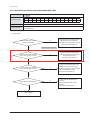
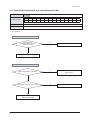
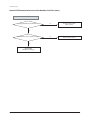
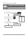
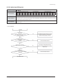
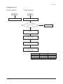
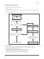
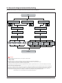
4-3-1 Outdoor Unit Operation Flow ............................................................................................................... 4-12
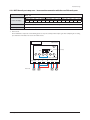
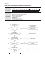
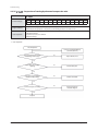
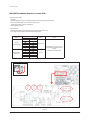
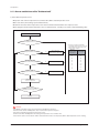
4-3-2 Main PCB has no power phenomenon ............................................................................................. 4-15
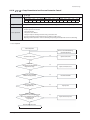
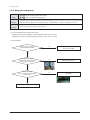
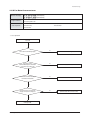
4-3-3 Communication Error between Indoor and Outdoor Units during Tracking.................... 4-16
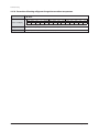
4-3-4 Communication Error between Indoor and Outdoor Units after Tracking ........................ 4-18
4-3-5 Communication error between main and sub Unit of outdoor unit or
between outdoor units ............................................................................................................................ 4-19
4-3-6 Internal Communication error of the Outdoor Unit C-Box ....................................................... 4-20
4-3-7 Internal PCB Communication error of the Outdoor Unit C-Box.............................................. 4-21
4-3-8 MCU branch part setup error-inconsecutive connection with the use
of 2 branch Parts ......................................................................................................................................... 4-23
Samsung Electronics
1
Section 0
Contents
4-3-9 MCU branch part setup error-Repeated setup for the same address over 3 times........ 4-24
4-3-10 MCU branch part setup error-non-installed address setup ................................................... 4-25
4-3-11 Setup Error for MCU Branch part-Setup Error for MCU Quantity Used ............................. 4-26
4-3-12 MCU branch part setup error-Overlapping Indoor unit Address setup ........................... 4-27
4-3-13 MCU branch part setup error_Set as being used without connection
to an Indoor unit ...................................................................................................................................... 4-28
4-3-14 MCU branch part setup error-Connect an Indoor unit to a branch part
not being used.......................................................................................................................................... 4-29
4-3-15 MCU branch part setup error-Connect more Indoor units than what is
actually set up in MCU........................................................................................................................... 4-30
4-3-16 MCU subcooler entrance/exit sensor error (Open/Short)....................................................... 4-31
4-3-17 Outdoor Temperature Sensor Error .................................................................................................. 4-32
4-3-18 Cond Out Temperature Sensor Error (Open/Short) ................................................................... 4-33
4-3-19 Outdoor Cond Out sensor breakway error ................................................................................... 4-34
4-3-20 Compressor Discharge or TOP 1/2 Temperature sensor error............................................... 4-35
4-3-21 Compressor Discharge or TOP temperature sensor breakway error.................................. 4-36
4-3-22 E269 : Suction Temperature sensor breakway error ................................................................. 4-37
4-3-23 High Pressure sensor error (Open/Short)....................................................................................... 4-38
4-3-24 Low Pressure sensor error (Open/Short) ........................................................................................ 4-39
4-3-25 Suction Temperature sensor error (Open/Short) ........................................................................ 4-40
4-3-26 Liquid Pipe Temperature sensor error (Open/Short)................................................................. 4-41
4-3-27 EVI In Temperature sensor error (Open/Short) ............................................................................ 4-42
4-3-28 EVI Out Temperature sensor error (Open/Short) ........................................................................ 4-43
4-3-29 Suction-2 Temperature Sensor Error (Open/Short) ................................................................... 4-44
4-3-30 Measures of other outdoor unit error ............................................................................................. 4-45
4-3-31 E407 : Comp. Down due to High Pressure Protection Control ............................................. 4-46
4-3-32 E410 : Comp. Down due to Low Pressure Protection Control ............................................... 4-47
4-3-33 E416 : Suspension of starting due to Compressure discharge
temperature sensor/Top temperature sensor ............................................................................. 4-48
4-3-34 3-phase Input Wiring error ................................................................................................................... 4-49
4-3-35 E428 : Suspension of starting by abnormal compression ratio........................................... 4-50
4-3-36 EVI EEV Open error .................................................................................................................................. 4-51
4-3-37 Refrigerant leakage error ...................................................................................................................... 4-52
4-3-38 Prevention of heating/cooling operation due to outdoor temperature .......................... 4-53
4-3-39 Prevention of heating refrigerant charge due to outdoor temperature .......................... 4-54
4-3-40 CH wire breaking error........................................................................................................................... 4-55
4-3-41 Fan starting error...................................................................................................................................... 4-56
4-3-42 Fan lock error ............................................................................................................................................. 4-58
4-3-43 Momentary Blackout error ......................................................................................................................... 4-59
4-3-44 Outdoor Fan Motor overheating ....................................................................................................... 4-60
4-3-45 Fan IPM Overheat error.......................................................................................................................... 4-61
4-3-46 Compressor starting error .................................................................................................................... 4-62
4-3-47 Inverter Overcurrent error .................................................................................................................... 4-64
4-3-48 Overvoltage/Low voltage error.......................................................................................................... 4-67
4-3-49 DC Link voltage sensor error ............................................................................................................... 4-68
4-3-50 Fan Motor Overcurrent error ............................................................................................................... 4-69
4-3-51 Input/Output Current sensor error ................................................................................................... 4-70
4-3-52 Outdoor Fan PCB Overvoltage/Low voltage error ..................................................................... 4-71
4-3-53 Hall IC(Fan) error ....................................................................................................................................... 4-72
4-3-54 Inverter Overheat error.......................................................................................................................... 4-73
4-3-55 Option setting error of outdoor unit ............................................................................................... 4-74
4-3-56 Model mismatching of Indoor unit .................................................................................................. 4-75
4-3-57 Error due to using single type outdoor unit in a module installation ............................... 4-76
2
Samsung Electronics
Section 0
Contents
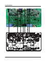
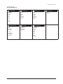
5. PCB Diagram and Parts List ............................................................................... 5-1
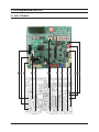
5-1 ASS'Y PCB MAIN ...........................................................................................................................................................5-1
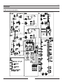
5-2 ASS'Y PCB MAIN-HUB ................................................................................................................................................5-3
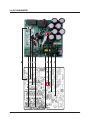
5-3 ASS’Y PCB INVERTER ..................................................................................................................................................5-7
5-4 ASS’Y PCB FAN ..............................................................................................................................................................5-9
5-5 ASS’Y PCB EMI .......................................................................................................................................................... 5-11
5-6 SUB-COMM ................................................................................................................................................................ 5-12
6. Wiring Diagram ................................................................................................... 6-1
6-1 AM080/100/120/140/160/180/200/220FXV666 ..........................................................................................6-1
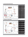
7. Cycle Diagram ...................................................................................................................7-1
7-1 AM080/100/120FXVAGH/EU ...................................................................................................................................7-1
7-2 AM140FXVAGH/EU ......................................................................................................................................................7-1
7-3 AM160/180/200/220FXVAGH/EU ..........................................................................................................................7-2
7-4 AM080/100/120FXVAGR/EU ....................................................................................................................................7-2
7-5 AM140FXVAGR/EU.......................................................................................................................................................7-3
7-6 AM160/180/200/220FXVAGR/EU ..........................................................................................................................7-3
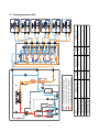
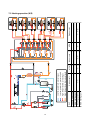
7-7Cooling operation (H/R) .............................................................................................................................................7-4
7-8 Main cooling operation (H/R) .................................................................................................................................7-5
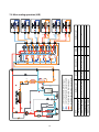
7-9 Heating operation (H/R) ............................................................................................................................................7-6
7-10 Main heating operation (H/R) ..............................................................................................................................7-7
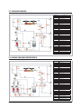
7-11 Cooling operation (H/P)..........................................................................................................................................7-8
7-12 Heating operation (H/P) .........................................................................................................................................7-9
7-13 Cycle Component Function Explanation .................................................................................................... 7-10
8. Key Options ......................................................................................................... 8-1
8-1 Outdoor unit option switch settings ...................................................................................................................8-1
8-2 How to set the key function of the outdoor unit ...........................................................................................8-2
8-3 How to check the view mode using a tact switch .........................................................................................8-4
9. Test Operation ..................................................................................................... 9-1
9-1 Auto Trial Operation....................................................................................................................................................9-1
9-1-1 Auto Trial Operation Synopsis ..................................................................................................................9-1
9-1-2 Auto Trial Operation functions.................................................................................................................9-3
9-1-3 How to troubleshoot of the "Undetermined"....................................................................................9-4
9-1-4 Auto Trial Operation Error Code ........................................................................................................... 9-13
9-2 Amount of refrigerant automatically checking............................................................................................ 9-14
Samsung Electronics
3
1. Precautions
1-1 Precautions for the Service
OUse the correct parts when changing the electric parts.
– Please check the labels and notices for the model name, proper voltage, and proper current for the electric parts.
OFully repair the connection for the types of harness when repairing the product after breakdown.
– A faulty connection can cause irregular noise and problems.
OWhen disassembling or assembling, make sure that the product is laid down on a work cloth.
– Doing so will prevent scratching to the exterior of the rear side of the product.
OCompletely remove dust or foreign substances on the housing, connection, and inspection parts when performing repairs.
– This can prevent fire hazards for tracking, short, etc.
OPlease tighten the service valve of the outdoor unit and the valve cap of the charging valve as securely as possible by using
a monkey spanner.
OCheck whether the parts are properly and securely assembled after performing repairs.
– These parts should be in the same condition as before the repair.
1-2 Precautions for the Static Electricity and PL
OPlease carefully handle the PCB power terminal during repair and measurement when it is turned on since it is vulnerable
to static electricity.
– Please wear insulation gloves before performing PCB repair and measurement.
OCheck if the place of installation is at least 2m away from electronic appliances such as TV, video players, and stereos.
– This can cause irregular noise or degrade the picture quality.
OPlease make sure the customer does not directly repair the product.
– Arbitrary dismantling may result in electric shock or fire.
1-3 Precautions for the Safety
ODo not pull or touch the power plug or the subsidiary power switch with wet hands.
– This may result in electric shock or fire.
OIf the power line or the power plug is damaged, then it must be changed since this is a hazard.
ODo not bend the wire too much or position it so that it can be damaged by a heavy object on top.
– This may result in electric shock or fire.
OThe use of multiple electric outlets should be prohibited.
– This may result in electric shock or fire.
OGround the connection if it is necessary.
– The connection must be grounded if there is any risk of electrical short due to water or moisture.
OUnplug the power or turn off the subsidiary power switch when changing or repairing electrical parts.
– Doing so will prevent electric shock.
OExplain to workers that the battery for the remote control needs to be separated for storage purposes when the product
will not be used for a long time.
– This can cause a problem for the remote control since battery fluid may trickle out.
Samsung Electronics
1-1
1-4 Precautions for Handling Refrigerant for Air Conditioner
Environmental Cautions: Air pollution due to gas release
OSafety Cautions
If liquid gas is released, then body parts that come into contact with it may experience frostbite/blister/numbness.
If a large amount of gas is released, then suffocation may occur due to lack of oxygen. If the released gas is heated, then noxious
gas may be produced by combustion.
OContainer Handling Cautions
Do not subject container to physical shock or overheating. (Flowage is possible while moving within the regulated pressure.)
1-5 Precautions for Welding the Air Conditioner Pipe
ODangerous or flammable objects around the pipe must be removed before the welding.
OIf the refrigerant is kept inside the product or the pipe, then remove the refrigerant prior to welding.
If the welding is carried out while the refrigerant is kept inside, the welding cannot be properly performed. This will also produce
noxious gas that is a health hazard. This leakage will also explode with the refrigerant and oil due to an increase in the refrigerant
pressure, posing a danger to workers.
OPlease remove the oxide produced inside the pipe during the welding with nitrogen gas.
Using another gas may cause harm to the product or others.
1-6 Precautions for Additional Supplement of Air Conditioner Refrigerant
OPrecisely calculate the refrigerant by using a scale and S-net, and proceed with the test operation.
Excessive supplement can cause harm to the product since it can cause an inflow of the liquid refrigerant into the compressor.
ODo not heat the refrigerant container for a forced injection.
This may cause harm to the product or others since the refrigerant container may burst.
ODo not operate the product after removing the product safety pressure switch and sensor.
If the product is blocked inside, then this may cause harm to the product or others due to the excess pressure increase of the
refrigerant gas.
1-7 Other Precautions
OThere should be no leakage of the pipes after installation. When withdrawing the refrigerant, the compressor should be
stopped before removing the connecting pipe.
If the compressor is operating while the refrigerant pipe is not correctly connected and the service valve is opened, then
air and other substances can enter the pipe. The interior of the refrigerant cycle may then build up excessive high pressure
resulting in explosion and damage.
1-2
Samsung Electronics
2. Product Specifications
2-1 The Feature of Product
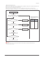
2-1-1 Feature
Q Dual Smart Inverter System
DSC System
DSI System
. DVI variable + DVI constant speed
. Dual Smart Inverter : SSC + SSC
. AC Motor
. BLDC Inverter Motor (20~160Hz driving)
. 3 generation, Vapor Injection
. 2 generation, Vapor Injection
(Performance maximization of low temperature heating)
High Pressure Refrigerant Outlet
High Pressure Refrigerant Outlet
High Pressure Refrigerant Outlet
Low Pressure
Refrigerant Inlet
Medium Pressure
Refrigerant Injection
Digital base
3 generation,
Vapor Injection
Low Pressure
Refrigerant Inlet
Medium Pressure
Refrigerant Inlet
Low Pressure
Refrigerant Inlet
3 generation,
Vapor Injection
Inverter base
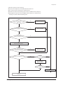
Q Dual SSC System Technology
When load changes, capacity amendment that is soft by continuous operation of Dual Inverter is available.
Step 1
ON
Capacity
OFF
Step 3
Step 2
ON
OFF
Step 4
Variable
ON
ON
ON
ON
Ŷ Compressor driving : When load changes, is variable by fast inverter frequency.
Ŷ Amenities elevation : ᇹ0.5°C
Samsung Electronics
2-1
Product Specifications
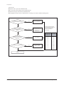
Feature (cont.)
Q Inverter circuit refrigerant cooling technology
Applied high efficiency refrigerant cooling circuit. Secured stable Inverter PCB cooling performance.
- Air cooling method : When natural convection / electric heat performance is low and is high load, efficiency is fallen.
- Refrigerant cooling system : Forced circulation / electric heat performance is high and control of (thermal conductivity is
10 times higher than air) load is available.
Refrigerant cooling system :
It is cooling technology of inverter circuit that use
refrigerating cycle technology.
Cooling of
inverter circuit
2-2
Samsung Electronics
Product Specifications
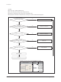
2-1-2 Changes in comparison to basic mode
Changed
part
Changed item
and feature
Basic
After changed
Change the color :
TOUCH GRAY
CABINET
ࣖ EARTH BROWN
Wire Harness installation part
change
LOGO change
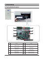
Q Control Box & PCB
Changed
part
Changed item
and feature
Basic
After changed
Monolayer structure ࣖ Double
Layer Structure
- Inverter technology integration
(Inverter control circuit
composition)
Control Box
- C/Box volume maximum use
structure
Built-in type Controller embodiment
- Integrated power supply
+ control unit
- Piping service easiness
Samsung Electronics
2-3
Product Specifications
Changes in comparison to basic mode (cont.)
Changed
part
Changed item
and feature
Basic
After changed
Change Main PCB
Main PCB
- Separation for load / control.
- Option resistance delete by model.
(standardization)
- When do PCB replace, need option
download.
Hub PCB newly application
Hub PCB
- Separation for load / control.
- Enhanced fixing of load / sensor wire.
Use controller of 3 phase power
FAN PCB
- Prevented phase unbalance.
- Temperature protection of IPM.
Applied inverter Compressor
Inverter PCB
(Compressor
Control PCB)
- Refrigerant cooling method
- Magnet S/W
͑ױDid Power Relay mount to PCB.
EMI PCB
Communication
Terminal block
2-4
3 phase power EMI PCB
- Fuse mount
-
Did Communication Terminal block
mount to PCB.
Samsung Electronics
Product Specifications
Changes in comparison to basic mode (cont.)
Q PIPE COOLING
Changed
part
Changed item
and feature
Pipe
New Pipe Cooling for cooling of
Cooling
Basic
After changed
Unapplied
inverter PCB.
Refrigerant cooling system : It is cooling technology of
inverter circuit that use refrigerating cycle technology.
Cooling of
inverter circuit
Q TUBE
Changed
part
Changed item
and feature
Basic
After changed [HP]
After changed [HR]
New inverter
Tube
structure
cycle technology
application
New piping
Samsung Electronics
2-5
Product Specifications
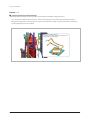
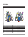
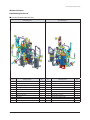
2-1-3 Structure of product (Heat Pump)
Small size
Large size
2-6
Samsung Electronics
Product Specifications
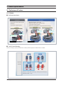
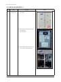
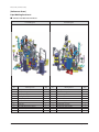
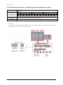
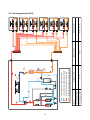
2-1-4 Structure of product (Heat Recovery)
Small size
Heat exchanger
CONTROL BOX
4-WAY V/V
Oil separator
Intercooler
Compressor
Liquid pipe
Accumulator
Low Pressure Gas Pipe
High Pressure Gas Pipe
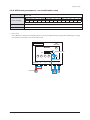
Large size
Heat exchanger
CONTROL BOX
4-WAY V/V
Oil separator
Accumulator
Intercooler
Compressor
Liquid pipe
Low Pressure Gas Pipe
Samsung Electronics
High Pressure Gas Pipe
2-7
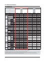
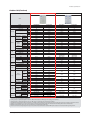
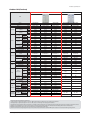
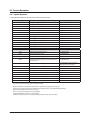
2-2 Product Specifications
2-2-1 Outdoor Unit
New Model
Comparative Model
TYPE
Model
Mode
Power
Horse Power
Capacity
AM080FXVAGH
HP
3/AC380~415/50
8
22.4
76,400
25.2
86,000
5.00
5.10
8.00
8.20
8.00
8.20
18.00
5.00
5.10
22.5 / 30
4.48
4.94
7.85
AM100FXVAGH
HP
3/AC380~415/50
10
28.0
95,500
31.5
107,500
6.80
6.70
10.90
10.70
10.90
10.70
21.10
6.80
6.70
29.9 / 40
4.12
4.70
7.25
AM120FXVAGH
HP
3/AC380~415/50
12
33.6
114,600
37.8
129,000
8.40
8.70
13.50
14.00
13.50
14.00
25.00
8.40
8.70
31.3 / 40
4.00
4.34
7.03
-
DS-GB052FA****
DS-GB066FA****
DS-GB066FA****
Type
Factory Charging
Type
Motor Output
kW
cc
kg
W
INV x1
4.70
FVC68D
3,900
R410A
5.5
Propeller + BLDC
400
INV x1
5.80
FVC68D
3,900
R410A
5.2
Propeller + BLDC
400
Airflow rate
㎥ /min
Cooling
Heating
Cooling 1)
Heating 2)
Current Input Cooling 1)
(Nominal)
Heating 2)
Cooling
Running
Heating
Current
Max.
Cooling
Power
Consumption Heating
MCA / MFA
Nominal Cooling
Nominal Heating
ESEER (HP)
Power Input
(Nominal)
Power
COP
Model
Compressor
Type
Output
Lubricant
Refrigerant
FAN
Type
Charging
Ø,V,Hz
HP
kW
btu/h
kW
btu/h
kW
A
A
A
A
kW
kW
A
-
Ø,mm
Liquid
Ø,inch
Ø,mm
Piping
Gas
Connections
Ø,inch
Pipe
Ø,mm
Dis. Gas
Ø,inch
Installation Max.Length m
Limitation Max.Height
m
Main Power(Below/about20m) mm2
Cable
Communication
mm2
DVM S HP
Net Weight
kg
DVM S HR
DVM
S
HP
Set
Shipping
kg
Dimension
Weight
DVM S HR
Net Dimension(WxHxD)
mm
Gross Dimension(WxHxD) mm
DVM S HP
Cooling
Operating
DVM S HR
ఁ
Temp Range
Heating
INV x1
5.80
FVC68D
3,900
R410A
5.5
Propeller + BLDC
400
RD080HHXG6
HP
3/AC380~415/50
8
22.4
76,400
25.2
86,000
8.80
11.40
18.40
5.20
5.46
ZPJ61KCE-TFD
ZPI61KCE-TFD
DVI x1 + FVl x1
4.36 + 4.36
3MAF POE
4,370
R410A
5.0
Propeller + BLDC
630
RD100HHXG6
HP
3/AC380~415/50
10
28.0
95,500
31.5
107,500
13.00
12.70
21.50
7.04
6.89
ZPJ61KCE-TFD
ZPI61KCE-TFD
DVI x1 + FVl x1
4.36 + 4.36
3MAF POE
4,370
R410A
5.0
Propeller + BLDC
630
RD120HHXG6
HP
3/AC380~415/50
12
33.6
114,600
37.8
129,000
20.00
18.40
28.40
9.20
8.50
ZPJ83KCE-TFD
ZPI83KCE-TFD
DVI x1 + FVl x1
5.87 + 5.87
3MAF POE
4,370
R410A
5.0
Propeller + BLDC
630
173
173
210
9.52
9.52
12.70
19.05
22.22
25.40
-
-
-
200
50(40)
1.5
VCTF 0.75~1.5(2P)
200
50(40)
2.5
VCTF 0.75~1.5(2P)
200
50(40)
4.0
VCTF 0.75~1.5(2P)
237
237
240
173
173
210
9.52
3/8"
19.05
3/4"
15.88
5/8"
200(220)
110(40)
4.0
VCTF 0.75~1.5(2P)
190.0
195.0
206.0
211.0
880x1,695x765
948x1,657x832
-5.0~48.0
-15.0~48.0
-20.0~24.0
9.52
3/8"
22.22
7/8"
19.05
3/4"
200(220)
110(40)
4.0
VCTF 0.75~1.5(2P)
190.0
195.0
206.0
211.0
880x1,695x765
948x1,657x832
-5.0~48.0
-15.0~48.0
-20.0~24.0
12.70
1/2"
28.58
1 1/8"
19.05
3.4"
200(220)
110(40)
4.0
VCTF 0.75~1.5(2P)
190.0
195.0
206.0
211.0
880x1,695x765
948x1,657x832
-5.0~48.0
-15.0~48.0
-20.0~24.0
253
253
256
880x1695x765
948x1912x832
880x1695x765
948x1912x832
880x1695x765
948x1912x832
-5.0 ~ 48
-5.0 ~ 48.0
-5.0 ~ 48.0
-20.0 ~ 24.0
-20.0 ~ 24.0
-20.0 ~ 24.0
1. Proper form capacity standard of air conditioning
- Cooling capacity : It is figures that appear in indoor 27˚C DB/19°C WB, outdoor 35˚C DB, length 7.5m of piping, fall 0m standard.
- Heating capacity : It is figures that appear in indoor 20˚C DB, outdoor 7˚C DB, length 7.5m of piping, fall 0m standard.
2. If proper form heating capacity is outdoor temperature 7˚C standard and outdoor temperature goes down by below zero, heating capacity can drop according to temperature condition.
3. Need special load calculation in case of use by main heating in the winter, and please buy product for low temperature that heating effect excels at low temperature.
4. Maximum length between outdoor and indoor units allows up to 200m (Equivalent length 220m).
5. If the indoor unit is below, height length allows up to 110m (If over 50m, decide whether to install the PDM kit). If the outdoor unit is below, allowable height length is 40m.
2-8
Samsung Electronics
Product Specifications
Outdoor Unit(Continue)
New Model
Comparative Model
TYPE
Model
Mode
Power
Horse Power
Capacity
Capacity
Heating
Cooling 1)
Heating 2)
Current Input Cooling 1)
(Nominal)
Heating 2)
Cooling
Running
Heating
Current
Max.
Cooling
Power
Consumption
Heating
MCA / MFA
Nominal Cooling
Nominal Heating
ESEER (HP)
Power Input
(Nominal)
Power
COP
Model
Compressor
Refrigerant
FAN
Pipe
Cable
Set
Dimension
Operating
Temp Range
Type
Output
Ø,V,Hz
HP
kW
btu/h
kW
btu/h
kW
A
A
A
A
kW
kW
A
-
kW
Type
Lubricant
Charging
cc
Type
Factory Charging
kg
Type
Motor Output
W
᎑͠
Airflow rate
ΞΚΟ
Ø,mm
Liquid
Ø,inch
Ø,mm
Piping
Gas
Connections
Ø,inch
Ø,mm
Dis. Gas
Ø,inch
Installation Max.Length m
Limitation Max.Height
m
Main Power(Below/about20m) mm2
Communication
mm2
DVM S HP
Net Weight
kg
DVM S HR
DVM S HP
Shipping
kg
Weight
DVM S HR
Net Dimension(WxHxD)
mm
Gross Dimension(WxHxD)
mm
DVM S HP
Cooling
DVM S HR
ఁ
Heating
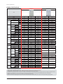
AM140FXVAGH
HP
3/AC380~415/50
14
40.0
136,000
45.0
153,000
8.90
9.50
14.30
15.20
14.30
15.20
25.00
8.90
9.50
31.3 / 40
4.49
4.74
7.02
AM160FXVAGH
HP
3/AC380~415/50
16
45.0
153,000
50.0
170,000
11.00
11.50
17.60
18.40
17.60
18.40
32.00
11.00
11.50
40 / 40
4.09
4.35
6.78
INV x2
4.7 x2
FVC68D
6,200
R410A
7.4
Propeller + BLDC
630 x 2
RD140HHXG6
HP
3/AC380~415/50
14
39.2
133,800
44.1
150,500
20.90
19.40
29.40
10.10
9.65
ZPJ83KCE-TFD
ZPI83KCE-TFD
DVI x1 + FVl x1
5.87 + 5.87
3MAF POE
4,370
R410A
7.0
Propeller + BLDC
630 x 2
RD160HHXG6
HP
3/AC380~415/50
16
44.8
152,900
50.0
172,000
22.00
27.20
38.30
12.00
11.30
ZPJ72KCE-TFD
ZPI72KCE-TFD
DVI x1 + FVl x2
5.16 + 5.16 x2
3MAF POE
6,540
R410A
7.0
Propeller + BLDC
630 x 2
DS-GB066FA****
DS-GB052FA****
INV x1
5.80
FVC68D
3,900
R410A
7.7
Propeller + BLDC
630 x 2
226
250
226
250
12.70
1/2"
28.58
1 1/8"
19.05
3/4"
200(220)
110(40)
4.0
VCTF 0.75~1.5(2P)
235.0
214.0
254.0
260.0
1295x1695x765
1363x1857x832
-5.0~48.0
-15.0~48.0
-20.0~24.0
12.70
1/2"
28.58
1 1/8"
22.22
7/8"
200(220)
110(40)
6.0
VCTF 0.75~1.5(2P)
278.0
184.0
297.0
303.0
1295x1695x765
1363x1857x832
-5.0~48.0
-15.0~48.0
-20.0~24.0
12.70
12.70
25.40
28.58
-
-
200
50(40)
4.0
VCTF 0.75~1.5(2P)
200
50(40)
6.0
VCTF 0.75~1.5(2P)
280
329
301
350
1295x1695x765
1363x1912x832
1295x1695x765
1363x1912x832
-5.0 ~ 48.0
-5.0 ~ 48.0
-20.0 ~ 24.0
-20.0 ~ 24.0
1. Proper form capacity standard of air conditioning
- Cooling capacity : It is figures that appear in indoor 27˚C DB/19°C WB, outdoor 35˚C DB, length 7.5m of piping, fall 0m standard.
- Heating capacity : It is figures that appear in indoor 20˚C DB, outdoor 7˚C DB, length 7.5m of piping, fall 0m standard.
2. If proper form heating capacity is outdoor temperature 7˚C standard and outdoor temperature goes down by below zero, heating capacity can drop according to temperature condition.
3. Need special load calculation in case of use by main heating in the winter, and please buy product for low temperature that heating effect excels at low temperature.
4. Maximum length between outdoor and indoor units allows up to 200m (Equivalent length 220m).
5. If the indoor unit is below, height length allows up to 110m (If over 50m, decide whether to install the PDM kit). If the outdoor unit is below, allowable height length is 40m.
Samsung Electronics
2-9
Product Specifications
Outdoor Unit(Continue)
New Model
Comparative Model
TYPE
Model
Mode
Power
Horse Power
Capacity
FAN
56.0
61.6
50.4
56.0
191,000
63.0
210,000
69.3
171,900
56.7
191,000
63.0
btu/h
193,500
215,000
236,000
193,500
215,000
12.80
11.90
20.70
19.10
20.70
19.10
39.10
12.88
11.90
48.9 / 50
3.91
4.76
6.59
15.19
13.90
24.40
22.30
24.40
22.30
42.50
15.19
13.90
52.5 / 75
3.69
4.53
6.56
17.35
16.70
27.80
26.80
27.80
26.80
44.50
17.35
16.70
52.5 / 75
3.55
4.15
6.25
-
DS-GB066FA****
DS-GB066FA****
DS-GB066FA****
kW
cc
kg
-
INV x2
5.8 x2
FVC68D
6,200
R410A
8.7
Propeller + BLDC
INV x2
5.8 x2
6,200
R410A
8.4
Propeller + BLDC
INV x2
5.8 x2
FVC68D
6,200
R410A
8.4
Propeller + BLDC
31.30
26.70
42.50
15.70
12.90
ZPJ83KCE-TFD
ZPI83KCE-TFD
DVI x1 + FVl x2
5.87 + 5.87 x2
3MAF POE
6,540
R410A
8.5
Propeller + BLDC
32.80
29.10
44.10
17.00
14.50
ZPJ83KCE-TFD
ZPI83KCE-TFD
DVI x1 + FVl x2
5.87 + 5.87 x2
3MAF POE
6,540
R410A
8.5
Propeller + BLDC
Motor Output
W
630 x2
630 x2
630 x2
630 x2
630 x2
Airflow rate
᎑ ͠ΞΚΟ
Ø,mm
Ø,inch
Ø,mm
Ø,inch
Ø,mm
Ø,inch
270
15.88
5/8"
28.58
1 1/8"
22.22
7/8"
275
15.88
5/8"
28.58
1 1/8"
28.58
1 1/8"
280
15.88
5/8"
28.58
1 1/8"
28.58
1 1/8"
270
275
15.88
15.88
28.58
28.58
-
-
m
200(220)
200(220)
200(220)
200
200
m
110(40)
110(40)
110(40)
50(40)
50(40)
mm2
mm2
10.0
VCTF 0.75~1.5(2P)
10.0
VCTF 0.75~1.5(2P)
10.0
VCTF 0.75~1.5(2P)
6.0
VCTF 0.75~1.5(2P)
10.0
VCTF 0.75~1.5(2P)
300.0
300.0
300.0
306.0
306.0
306.0
340.0
349.0
319.0
319.0
319.0
325.0
1295x1695x765
1363x1857x832
-5.0 ~ 48.0
-15.0~48.0
-20.0 ~ 24.0
325.0
1295x1695x765
1363x1857x832
-5.0 ~ 48.0
-15.0~48.0
-20.0 ~ 24.0
325.0
1295x1695x765
1363x1857x832
-5.0 ~ 48.0
-15.0~48.0
-20.0 ~ 24.0
361.0
370.0
1295x1695x765
1363x1912x832
1295x1695x765
1363x1912x832
-5.0~ 48.0
-5.0 ~ 48.0
-20.0 ~ 24.0
-20.0 ~ 24.0
Cooling 1)
Heating 2)
Cooling 1)
Heating 2)
Cooling
Running
Heating
Current
Max.
Power
Cooling
Consumption Heating
MCA / MFA
Nominal Cooling
Nominal Heating
ESEER (HP)
Type
Output
Type
Charging
Type
Factory Charging
Type
Liquid
Pipe
Piping
Connections
Gas
Dis. Gas
Installation
Limitation
Cable
Max.Length
Max.Height
Main Power(Below/about20m)
Communication
Net Weight
Set
Dimension
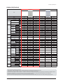
RD200HHXG6
HP
3/AC380~415/50
20
50.4
Lubricant
Refrigerant
RD180HHXG6
HP
3/AC380~415/50
18
171,900
56.7
Model
Compressor
AM220FXVAGH
HP
3/AC380~415/50
22
kW
Power Input
(Nominal)
Current Input
(Nominal)
COP
AM200FXVAGH
HP
3/AC380~415/50
20
btu/h
kW
Cooling
Heating
Power
Ø,V,Hz
HP
AM180FXVAGH
HP
3/AC380~415/50
18
Shipping
Weight
DVM S HP
DVM S HR
DVM S HP
DVM S HR
Net Dimension(WxHxD)
Gross Dimension(WxHxD)
DVM S HP
Operating
Cooling
DVM S HR
Temp Range
Heating
kW
A
A
A
A
kW
kW
A
-
kg
kg
mm
mm
ఁ
1. Proper form capacity standard of air conditioning
- Cooling capacity : It is figures that appear in indoor 27˚C DB/19°C WB, outdoor 35˚C DB, length 7.5m of piping, fall 0m standard.
- Heating capacity : It is figures that appear in indoor 20˚C DB, outdoor 7˚C DB, length 7.5m of piping, fall 0m standard.
2. If proper form heating capacity is outdoor temperature 7˚C standard and outdoor temperature goes down by below zero, heating capacity can drop according to temperature condition.
3. Need special load calculation in case of use by main heating in the winter, and please buy product for low temperature that heating effect excels at low temperature.
4. Maximum length between outdoor and indoor units allows up to 200m (Equivalent length 220m).
5. If the indoor unit is below, height length allows up to 110m (If over 50m, decide whether to install the PDM kit). If the outdoor unit is below, allowable height length is 40m.
2-10
Samsung Electronics
Product Specifications
Outdoor Unit(Continue)
New Model
Comparative Model
TYPE
Model
Mode
Power
Horse Power
Capacity
Ø,V,Hz
HP
kW
btu/h
kW
btu/h
Capacity
Heating
Cooling 1)
Heating 2)
Current Input Cooling 1)
(Nominal)
Heating 2)
Cooling
Running
Heating
Current
Max.
Cooling
Power
Consumption
Heating
MCA / MFA
Nominal Cooling
Nominal Heating
ESEER (HP)
Power Input
(Nominal)
Power
COP
Model
Compressor
Refrigerant
FAN
Type
Charging
Type
Factory Charging
Type
Motor Output
Airflow rate
Liquid
Pipe
Piping
Connections
A
A
A
A
kW
kW
A
-
Type
Output
Lubricant
kW
Gas
Dis. Gas
Installation Max.Length
Limitation Max.Height
Main Power(Below/about20m)
Cable
Communication
DVM S HP
Net Weight
DVM S HR
DVM S HP
Shipping
Set
Dimension
Weight
DVM S HR
Net Dimension(WxHxD)
Gross Dimension(WxHxD)
DVM S HP
Cooling
Operating
DVM S HR
Temp Range
Heating
kW
cc
kg
W
᎑ ͠ΞΚΟ
Ø,mm
Ø,inch
Ø,mm
Ø,inch
Ø,mm
Ø,inch
m
m
mm2
mm2
kg
kg
mm
mm
ఁ
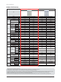
AM080FXVAGR
HR
3/AC380~415/50
8
22.4
76,400
25.2
86,000
5.00
5.10
8.00
8.20
8.00
8.20
18.00
5.00
5.10
22.5 / 30
4.48
4.94
7.85
AM100FXVAGR
HR
3/AC380~415/50
10
28.0
95,500
31.5
107,500
6.80
6.70
10.90
10.70
10.90
10.70
21.10
6.80
6.70
29.9 / 40
4.12
4.70
7.25
AM120FXVAGR
HR
3/AC380~415/50
12
33.6
114,600
37.8
129,000
8.40
8.70
13.50
14.00
13.50
14.00
25.00
8.40
8.70
31.3 / 40
4.00
4.34
7.03
DS-GB052FA****
DS-GB066FA****
DS-GB066FA****
INV x1
4.70
FVC68D
3,900
R410A
5.5
Propeller + BLDC
400
173
9.52
3/8"
19.05
3/4"
15.88
5/8"
200(220)
110(40)
4.0
VCTF 0.75~1.5(2P)
190.0
195.0
206.0
211.0
880x1,695x765
948x1,657x832
-5.0~48.0
-15.0~48.0
-20.0~24.0
INV x1
5.80
FVC68D
3,900
R410A
5.2
Propeller + BLDC
400
173
9.52
3/8"
22.22
7/8"
19.05
3/4"
200(220)
110(40)
4.0
VCTF 0.75~1.5(2P)
190.0
195.0
206.0
211.0
880x1,695x765
948x1,657x832
-5.0~48.0
-15.0~48.0
-20.0~24.0
INV x1
5.80
FVC68D
3,900
R410A
5.5
Propeller + BLDC
400
210
12.70
1/2"
28.58
1 1/8"
19.05
3.4"
200(220)
110(40)
4.0
VCTF 0.75~1.5(2P)
190.0
195.0
206.0
211.0
880x1,695x765
948x1,657x832
-5.0~48.0
-15.0~48.0
-20.0~24.0
RD080HRXG6
HR
3/AC380~415/50
8
22.4
76,400
25.2
86,000
8.80
11.40
18.40
5.20
5.46
ZPJ61KCE-TFD
ZPI61KCE-TFD
DVI x1 + FVl x1
4.36 + 4.36
3MAF POE
4,370
R410A
5.0
Propeller + BLDC
630
173
RD100HRXG6
HR
3/AC380~415/50
10
28.0
95,500
31.5
107,500
13.00
12.70
21.50
7.04
6.89
ZPJ61KCE-TFD
ZPI61KCE-TFD
DVI x1 + FVl x1
4.36 + 4.36
3MAF POE
4,370
R410A
5.0
Propeller + BLDC
630
173
RD120HRXG6
HR
3/AC380~415/50
12
33.6
114,600
37.8
129,000
20.00
18.40
28.40
9.20
8.50
ZPJ83KCE-TFD
ZPI83KCE-TFD
DVI x1 + FVl x1
5.87 + 5.87
3MAF POE
4,370
R410A
5.0
Propeller + BLDC
630
210
9.52
9.52
12.70
19.05
22.22
25.40
15.88
19.05
22.22
200
50(40)
1.5
VCTF 0.75~1.5(2P)
200
50(40)
2.5
VCTF 0.75~1.5(2P)
200
50(40)
4.0
VCTF 0.75~1.5(2P)
243
243
243
259
259
259
880x1695x765
948x1912x832
880x1695x765
948x1912x832
880x1695x765
948x1912x832
-5.0 ~ 48.0
-5.0 ~ 48.0
-5.0 ~ 48.0
-20.0 ~ 24.0
-20.0 ~ 24.0
-20 .0~ 24.0
1. Proper form capacity standard of air conditioning
- Cooling capacity : It is figures that appear in indoor 27˚C DB/19°C WB, outdoor 35˚C DB, length 7.5m of piping, fall 0m standard.
- Heating capacity : It is figures that appear in indoor 20˚C DB, outdoor 7˚C DB, length 7.5m of piping, fall 0m standard.
2. If proper form heating capacity is outdoor temperature 7˚C standard and outdoor temperature goes down by below zero, heating capacity can drop according to temperature condition.
3. Need special load calculation in case of use by main heating in the winter, and please buy product for low temperature that heating effect excels at low temperature.
4. Maximum length between outdoor and indoor units allows up to 200m (Equivalent length 220m).
5. If the indoor unit is below, height length allows up to 110m (If over 50m, decide whether to install the PDM kit). If the outdoor unit is below, allowable height length is 40m.
Samsung Electronics
2-11
Product Specifications
Outdoor Unit(Continue)
New Model
Comparative Model
TYPE
Model
Mode
Power
Horse Power
Capacity
Capacity
Heating
Cooling 1)
Heating 2)
Current Input Cooling 1)
(Nominal)
Heating 2)
Cooling
Running
Heating
Current
Max.
Cooling
Power
Consumption
Heating
MCA / MFA
Nominal Cooling
Nominal Heating
ESEER (HP)
Power Input
(Nominal)
Power
COP
Model
Compressor
Refrigerant
FAN
Pipe
Cable
Operating
Temp Range
AM160FXVAGR
HR
3/AC380~415/50
16
45.0
153,000
50.0
170,000
11.00
11.50
17.60
18.40
17.60
18.40
32.00
11.00
11.50
40 / 40
4.09
4.35
6.78
DS-GB066FA****
DS-GB052FA****
INV x1
5.80
FVC68D
3,900
R410A
7.7
Propeller + BLDC
630 x 2
226
12.70
1/2"
28.58
1 1/8"
19.05
3/4"
200(220)
110(40)
INV x2
4.7 x2
FVC68D
6,200
R410A
7.4
Propeller + BLDC
630 x 2
250
12.70
1/2"
28.58
1 1/8"
22.22
7/8"
200(220)
110(40)
mm2
4.0
mm2
Ø,V,Hz
HP
kW
btu/h
kW
btu/h
kW
A
A
A
A
kW
kW
A
-
Type
Output
kW
Type
Lubricant
Charging
cc
Type
Factory Charging
kg
Type
Motor Output
W
Airflow rate
᎑ ͠ΞΚΟ
Ø,mm
Liquid
Ø,inch
Ø,mm
Piping
Gas
Connections
Ø,inch
Ø,mm
Dis. Gas
Ø,inch
m
Installation Max.Length
Limitation Max.Height
m
Main Power(Below/
about20m)
Communication
DVM S HP
DVM S HR
DVM S HP
Shipping
Weight
DVM S HR
Net Dimension(WxHxD)
Gross Dimension(WxHxD)
DVM S HP
Cooling
DVM S HR
Heating
Net Weight
Set
Dimension
AM140FXVAGR
HR
3/AC380~415/50
14
40.0
136,000
45.0
153,000
8.90
9.50
14.30
15.20
14.30
15.20
25.00
8.90
9.50
31.3 / 40
4.49
4.74
7.02
kg
kg
mm
mm
ఁ
RD140HRXG6
HR
3/AC380~415/50
14
39.2
133,800
44.1
150,500
20.90
19.40
29.40
10.10
9.65
ZPJ83KCE-TFD
ZPI83KCE-TFD
DVI x1 + FVl x1
5.87 + 5.87
3MAF POE
4,370
R410A
7.0
Propeller + BLDC
630 x 2
226
RD160HRXG6
HR
3/AC380~415/50
16
44.8
152,900
50.0
172,000
22.00
27.20
38.30
12.00
11.30
ZPJ72KCE-TFD
ZPI72KCE-TFD
DVI x1 + FVl x2
5.16 + 5.16 x2
3MAF POE
6,540
R410A
7.0
Propeller + BLDC
630 x 2
250
12.70
12.70
25.40
28.58
22.22
25.40
200
50(40)
200
50(40)
6.0
4.0
6.0
VCTF 0.75~1.5(2P)
VCTF 0.75~1.5(2P)
VCTF 0.75~1.5(2P)
VCTF 0.75~1.5(2P)
235.0
214.0
254.0
260.0
1295x1695x765
1363x1857x832
-5.0~48.0
-15.0~48.0
-20.0~24.0
278.0
184.0
297.0
303.0
1295x1695x765
1363x1857x832
-5.0~48.0
-15.0~48.0
-20.0~24.0
293
338
314
359
1295x1695x765
1363x1912x832
1295x1695x765
1363x1912x832
-5 .0~ 48.0
-5.0~ 48.0
-20.0~ 24.0
-20.0~ 24.0
1. Proper form capacity standard of air conditioning
- Cooling capacity : It is figures that appear in indoor 27˚C DB/19°C WB, outdoor 35˚C DB, length 7.5m of piping, fall 0m standard.
- Heating capacity : It is figures that appear in indoor 20˚C DB, outdoor 7˚C DB, length 7.5m of piping, fall 0m standard.
2. If proper form heating capacity is outdoor temperature 7˚C standard and outdoor temperature goes down by below zero, heating capacity can drop according to temperature condition.
3. Need special load calculation in case of use by main heating in the winter, and please buy product for low temperature that heating effect excels at low temperature.
4. Maximum length between outdoor and indoor units allows up to 200m (Equivalent length 220m).
5. If the indoor unit is below, height length allows up to 110m (If over 50m, decide whether to install the PDM kit). If the outdoor unit is below, allowable height length is 40m.
2-12
Samsung Electronics
Product Specifications
Outdoor Unit(Continue)
New Model
Comparative Model
TYPE
Model
Mode
Power
Horse Power
Capacity
Capacity
Heating
Cooling 1)
Heating 2)
Current Input Cooling 1)
(Nominal)
Heating 2)
Cooling
Running
Heating
Current
Max.
Cooling
Power
Consumption
Heating
MCA / MFA
Nominal Cooling
Nominal Heating
ESEER (HP)
Power Input
(Nominal)
Power
COP
Model
Compressor
Refrigerant
FAN
Pipe
Cable
Ø,V,Hz
HP
kW
btu/h
kW
btu/h
kW
A
A
A
A
kW
kW
A
-
Type
Output
kW
Type
Lubricant
Charging
cc
Type
Factory Charging
kg
Type
Motor Output
W
Airflow rate
᎑ ͠ΞΚΟ
Ø,mm
Liquid
Ø,inch
Ø,mm
Piping
Gas
Connections
Ø,inch
Ø,mm
Dis. Gas
Ø,inch
m
Installation Max.Length
Limitation Max.Height
m
Main Power(Below/
about20m)
Communication
DVM S HP
Net Weight
DVM S HR
Shipping
DVM S HP
Set
DVM S HR
Weight
Dimension
Net Dimension(WxHxD)
Gross Dimension(WxHxD)
DVM S HP
Cooling
Operating
DVM S HR
Temp Range
Heating
AM180FXVAGR
HR
3/AC380~415/50
18
50.4
171,900
56.7
193,500
12.80
11.90
20.70
19.10
20.70
19.10
39.10
12.88
11.90
48.9 / 50
3.91
4.76
6.59
AM200FXVAGR
HR
3/AC380~415/50
20
56.0
191,000
63.0
215,000
15.19
13.90
24.40
22.30
24.40
22.30
42.50
15.19
13.90
52.5 / 75
3.69
4.53
6.56
AM220FXVAGR
HR
3/AC380~415/50
22
61.6
210,000
69.3
236,000
17.35
16.70
27.80
26.80
27.80
26.80
44.50
17.35
16.70
52.5 / 75
3.55
4.15
6.25
DS-GB066FA****
DS-GB066FA****
DS-GB066FA****
INV x2
5.8 x2
FVC68D
6,200
R410A
8.7
Propeller + BLDC
630 x2
270
INV x2
5.8 x2
6,200
R410A
8.4
Propeller + BLDC
630 x2
275
INV x2
5.8 x2
FVC68D
6,200
R410A
8.4
Propeller + BLDC
630 x2
280
15.88
15.88
15.88
5/8"
5/8"
5/8"
28.58
28.58
28.58
1 1/8"
1 1/8"
1 1/8"
22.22
28.58
28.58
RD180HRXG6
HR
3/AC380~415/50
18
50.4
171,900
56.7
193,500
31.30
26.70
42.50
15.70
12.90
ZPJ83KCE-TFD
ZPI83KCE-TFD
DVI x1 + FVl x2
5.87 + 5.87 x2
3MAF POE
6,540
R410A
8.5
Propeller + BLDC
630 x2
270
RD200HRXG6
HR
3/AC380~415/50
20
56.0
191,000
63.0
215,000
32.80
29.10
44.10
17.00
14.50
ZPJ83KCE-TFD
ZPI83KCE-TFD
DVI x1 + FVl x2
5.87 + 5.87 x2
3MAF POE
6,540
R410A
8.5
Propeller + BLDC
630 x2
275
15.88
15.88
28.58
28.58
28.58
28.58
200
50(40)
7/8"
1 1/8"
1 1/8"
200(220)
200(220)
200(220)
110(40)
110(40)
110(40)
200
50(40)
mm2
10.0
10.0
10.0
6.0
10.0
mm2
VCTF 0.75~1.5(2P)
VCTF 0.75~1.5(2P)
VCTF 0.75~1.5(2P)
VCTF 0.75~1.5(2P)
VCTF 0.75~1.5(2P)
300.0
306.0
319.0
325.0
1295x1695x765
1363x1857x832
-5.0 ~ 48.0
-15.0~48.0
-20.0 ~ 24.0
300.0
306.0
319.0
325.0
1295x1695x765
1363x1857x832
-5.0 ~ 48.0
-15.0~48.0
-20.0 ~ 24.0
300.0
306.0
319.0
325.0
1295x1695x765
1363x1857x832
-5.0 ~ 48.0
-15.0~48.0
-20.0 ~ 24.0
349
355
369
376
1295x1695x765
1363x1912x832
1295x1695x765
1363x1912x832
-5.0 ~ 48.0
-5.0 ~ 48.0
-20.0 ~ 24.0
-20.0~ 24.0
kg
kg
mm
mm
ఁ
1. Proper form capacity standard of air conditioning
- Cooling capacity : It is figures that appear in indoor 27˚C DB/19°C WB, outdoor 35˚C DB, length 7.5m of piping, fall 0m standard.
- Heating capacity : It is figures that appear in indoor 20˚C DB, outdoor 7˚C DB, length 7.5m of piping, fall 0m standard.
2. If proper form heating capacity is outdoor temperature 7˚C standard and outdoor temperature goes down by below zero, heating capacity can drop according to temperature condition.
3. Need special load calculation in case of use by main heating in the winter, and please buy product for low temperature that heating effect excels at low temperature.
4. Maximum length between outdoor and indoor units allows up to 200m (Equivalent length 220m).
5. If the indoor unit is below, height length allows up to 110m (If over 50m, decide whether to install the PDM kit). If the outdoor unit is below, allowable height length is 40m.
Samsung Electronics
2-13
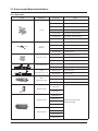
2-3 Accessory and Option Specifications
2-3-1 Accessories
Picture
Classification
Y-Joint
Y-Joint
(Only H/R)
Distribution header
Model Name
Remark
MXJ-YA1509M
15.0 kW and below
MXJ-YA2512M
Over 15.0 kW~40.6 kW and below
MXJ-YA2812M
Over 40.6 kW~46.4 kW and below
MXJ-YA2815M
Over 46.4 kW~69.6 kW and below
MXJ-YA3419M
Over 69.6 kW~98.6 kW and below
MXJ-YA4119M
Over 98.6 kW~139.2 kW and below
MXJ-YA4422M
Over 139.2 kW
MXJ-YA1500M
23.2 kW and below
MXJ-YA2500M
Over 23.2 kW~69.6 kW and below
MXJ-YA3100M
Over 69.6 kW~139.2 kW and below
MXJ-YA3800M
139.2 kW and below
MXJ-HA2512M
46.4 kW and below (for 4 rooms)
MXJ-HA3115M
69.6 kW and below (for 8 rooms)
MXJ-HA3819M
Over 69.6 kW (for 8 rooms)
MXJ-TA3819M
139.2 kW and below
MXJ-TA4422M
145 kW and below
MXJ-TA3100M
139.2 kW and below
MXJ-TA3800M
145 kW and Over
MCU-S6NEE1N
6 ROOM
MCU-S4NEE1N
4 ROOM
MCU-S4NEE2N
4 ROOM
Y-Joint -Outdoor Unit
Y-Joint
(Only H/R)-Outdoor Unit
MCU
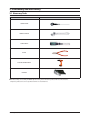
(Mode Control Unit)
MEV-E24SA
EEV KIT (1 Room)
MEV-E32SA
MXD-E24K132A
MXD-E24K200A
EEV KIT (2 Room)
MXD-E32K200A
Applty to products without EEV
(Wall mount & Ceiling)
MXD-E24K232A
MXD-E24K132A
MXD-E24K300A
EEV KIT (3 Room)
MXD-E32K224A
MXD-E32K300A
2-14
Samsung Electronics
3. Disassembly and Reassembly
3-1 Necessary Tools
Item
Remark
+SCREW DRIVER
MONKEY SPANNER
-SCREW DRIVER
NIPPER
ELECTRIC MOTION DRIVER
L-WRENCH
OFor “disassembly and assembly” DVM PLUS Ⅳ indoor unit, please refer to the products with the same structures.
Only those products that are not specified elsewhere are described here.
Samsung Electronics
3-1
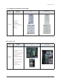
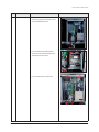
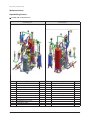
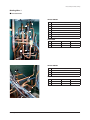
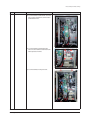
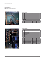
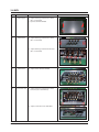
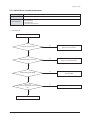
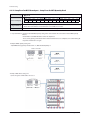
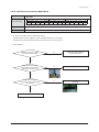
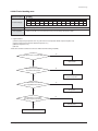
3-2 Disassembly and Reassembly
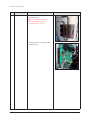
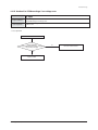
3-2-1 AM080/100/120FXV666
No.
Parts
Procedure
1
Electrical
1) 14 screws that is fixing CABINET remove.(Use +
equipment Part
Remark
Screw driver)
2) Remove 4 screws that is fixing and separate
Cover Control Box.
(Use + Screw driver)
3) Power, Compressor, Valve, Motor, Sensor connector connected to ASSY PCB remove.
3-2
Samsung Electronics
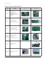
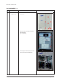
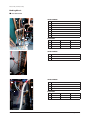
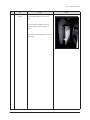
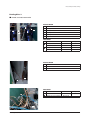
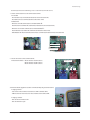
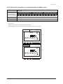
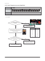
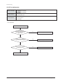
Disassembly and Reassembly
No.
Parts
Procedure
Remark
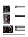
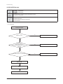
4) 2 screws had fixed in terminal block cover
when change power terminal block, communication terminal block remove.
5) 2 screws had fixed in terminal block after
remove 4 screws had fixed to Cabinet for terminal block protection remove.
6) 5 screws had fixed to Front part remove.
Samsung Electronics
3-3
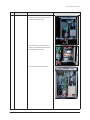
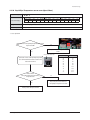
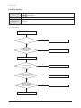
Disassembly and Reassembly
No.
Parts
Procedure
Remark
7) 6 screws had fixed on side refrigerant cooling
part outside remove .
Do not separate Heat Sink pulling Assy
Piping Cooling piping compulsorily.
(Is responsible for parts damage.)
8) 2 screws had fixed on side refrigerant cooling
part inside remove.
3-4
Samsung Electronics
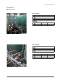
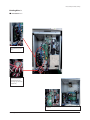
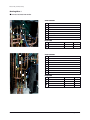
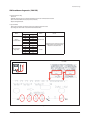
Disassembly and Reassembly
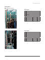
Binding Wire 1
غAM080/100/120FXVAGH
VALVE & SENSOR
No
Valve & Sensor
4WAY Valve
High Pressure Sensor
Suction Sensor
EVI Out Sensor
INSULATION
No
Model
Insu Code
AM080/100/120FXVAGH
DB62-04154C
AM080/100/120FXVAGH
DB62-03808B
AM080/100/120FXVAGH
DB62-03808C
Binding Wire
VALVE & SENSOR
No
Valve & Sensor
Expansion Valve
EVI EEV Valve
Accum Oil Return Valve
EVI In Sensor
INSULATION
No
Samsung Electronics
Model
Insu Code
AM080/100/120FXVAGH
DB62-03808C
AM080/100/120FXVAGH
DB62-03808E
Binding Wire
3-5
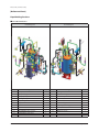
Disassembly and Reassembly
Binding Wire 2
غAM080/100/120FXVAGH
VALVE & SENSOR
No
Valve & Sensor
Low Pressure Sensor
VALVE & SENSOR
No
Valve & Sensor
Cond Out Sensor
Outdoor Temperature Sensor
VALVE & SENSOR
No
Valve & Sensor
Comp Top Sensor
Discharge Sensor
High Pressure Switch
INSULATION
No
3-6
Model
Insu Code
AM080/100/120FXVAGH
DB62-03808D
Binding Wire
Samsung Electronics
Disassembly and Reassembly
Binding Wire 1
غAM080/100/120FXVAGR
VALVE & SENSOR
No
Valve & Sensor
4WAY Valve
High Pressure Sensor
Suciton 1 Sensor
Suciton 2 Sensor
EVI Out Sensor
Main Cooling Valve
EVI Bypass Valve
EVI SOL Valve
INSULATION
No
Model
Insu Code
AM080/100/120FXVAGR
DB62-03808B
AM120FXVAGR
DB62-03808G
AM080/100/120FXVAGR
DB62-04154B
Binding Wire
VALVE & SENSOR
No
Valve & Sensor
Main EEV Valve
OD EEV Valve
Accum Return Valve
EVI In Sensor
Hot Gas 1 Valve
Hot Gas 2 Valve
Liquid Sensor
INSULATION
No
Samsung Electronics
Model
Insu Code
AM080/100/120FXVAGR
DB62-03808E
AM080/100/120FXVAGR
DB62-04154B
AM080/100/120FXVAGR
DB62-03808C
Binding Wire
3-7
Disassembly and Reassembly
Binding Wire 2
غAM080/100/120FXVAGR
VALVE & SENSOR
No
Valve & Sensor
Low Pressure Sensor
EVI EEV Valve
VALVE & SENSOR
No
Valve & Sensor
Cond Out Sensor
Outdoor Temperature Sensor
VALVE & SENSOR
No
Valve & Sensor
Comp Top Sensor
Discharge Sensor
High Pressure Switch
INSULATION
No
3-8
Model
Insu Code
AM080/100/120FXVAGH
DB62-03808D
Binding Wire
Samsung Electronics
Disassembly and Reassembly
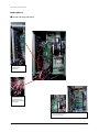
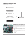
Binding Wire 3
غAM080/100/120FXV666
ـComp Wire fix by
Holder Wire.
ـFix Comp Wire-Core to
Bracket Beam Control
Box using large size
Cable Tie(350mm).
ـSeparate double layer structure of C/Box after remove 3 screws and
connector.
Samsung Electronics
3-9
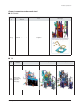
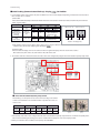
Disassembly and Reassembly
[Reference Sheet]
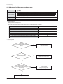
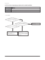
Pipe Welding Position
غAM080/100/120FXVAGH/EU
Front Welding Parts
No.
3-10
Welding Position
Rear Welding Parts
Q'ty
No.
1
1
Cooling+Subcooler
1
1
2
Subcooler+EVI Bypass
1
1
3
Accum+4Way
1
1
4
Accum+Accum Oil Vavle
1
1
5
Accum+EVI Bypass
1
Oil Return+Suction
1
6
Vapor Injection+EVI Bypass
1
Hot Gas Vavle +Suction
1
7
Hot Gas Vavle +Oil Sepa Out
1
1
8
4Way+Cond In
9
Expansion+Cond Out
1
Comp+Suction
2
Comp+Discharge
3
Comp+Vapor Injection
4
Discharge+Oil Sepa
5
4Way+Oil Sepa Out
6
7
8
Expansion+Subcooler
9
Pinch Pipe
1
10
Accum Oil Return Valve + Suction
1
11
Liquid Ball Vavle +Colling
1
12
Accum+Suction
1
Welding Position
Q'ty
Samsung Electronics
Disassembly and Reassembly
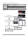
[Reference Sheet]
Pipe Welding Position
غAM080/100/120FXVAGR/EU
Front Welding Parts
Rear Welding Parts
No.
Welding Position
Q'ty
No.
Welding Position
Q'ty
1
Comp+Suction
1
1
Cooling+Subcooler
1
2
Comp+Discharge
1
2
Subcooler+EVI Bypass
1
3
Comp+Vapor Injection
1
3
Accum+4Way
1
4
Discharge+Oil Sepa
1
4
Accum+Accum Oil Vavle
1
5
4Way+Oil Sepa Out
1
5
Accum+EVI Bypass
1
6
4Way+Cond In
1
6
Vapor Injection+EVI Bypass
1
7
Expansion+Cond Out
1
7
Hot Gas Vavle +Oil Sepa Out
1
8
Pinch Pipe
1
8
Oil Return+Suction
9
Accum Oil Return Valve+Suction
1
9
LQD Ball Valve+Subcooler
10
Subcooler+Expansion
1
11
LQD Ball Valve+Cooling
1
12
Accum+Suction
1
Samsung Electronics
3-11
Disassembly and Reassembly
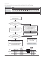
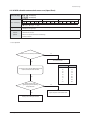
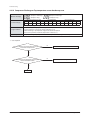
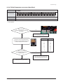
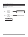
3-2-2 AM140FXV666
No.
Parts
Procedure
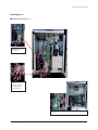
1
Electrical
1) 11 screws that is fixing CABINET remove.(Use +
equipment Part
Remark
Screw driver)
2) Remove 4 screws that is fixing and separate
Cover Control Box.
(Use + Screw driver)
3) Power, Compressor, Valve, Motor, Sensor connector connected to ASSY PCB remove.
3-12
Samsung Electronics
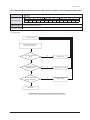
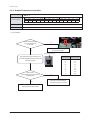
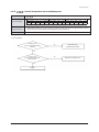
Disassembly and Reassembly
No.
Parts
Procedure
Remark
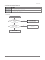
4) 2 screws had fixed in terminal block cover
when change power terminal block, communication terminal block remove.
5) 2 screws had fixed in terminal block after
remove 4 screws had fixed to Cabinet for terminal block protection remove.
6) 5 screws had fixed to Front part remove.
Samsung Electronics
3-13
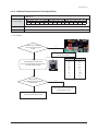
Disassembly and Reassembly
No.
Parts
Procedure
Remark
7) 6 screws had fixed on side refrigerant cooling
part outside remove .
Do not separate Heat Sink pulling Assy
Piping Cooling piping compulsorily.
(Is responsible for parts damage.)
8) 2 screws had fixed on side refrigerant cooling
part inside remove.
3-14
Samsung Electronics
Disassembly and Reassembly
Binding Wire 1
غAM140FXVAGH
VALVE & SENSOR
No
Valve & Sensor
4WAY Valve
High Pressure Sensor
EVI Bypass Valve
INSULATION
No
Model
Insu Code
AM140FXVAGH
DB62-03808G
Binding Wire
VALVE & SENSOR
No
Valve & Sensor
EVI SOL Valve
Low Pressure Sensor
Hot Gas Valve
INSULATION
No
Samsung Electronics
Model
Insu Code
AM140FXVAGH
DB62-04154D
AM140FXVAGH
DB62-04154D
Binding Wire
3-15
Disassembly and Reassembly
Binding Wire 2
ͥ͢͡;Ͳ͑غͷΉ·Ͳ
VALVE & SENSOR
No
Valve & Sensor
Expansion Valve
EVI EEV Valve
Accum Oil Return Valve
High Pressure Switch
INSULATION
No
Model
Insu Code
AM140FXVAGH
DB62-03808C
AM140FXVAGH
DB62-03808D
AM140FXVAGH
DB62-03808E
Binding Wire
VALVE & SENSOR
No
Valve & Sensor
Cond Out Sensor
Outdoor Temperature Sensor
VALVE & SENSOR
No
Valve & Sensor
Comp Top Sensor
Discharge Sensor
INSULATION
No
3-16
Model
Insu Code
AM140FXVAGH
DB62-03808C
Binding Wire
Samsung Electronics
Disassembly and Reassembly
Binding Wire 1
غAM140FXVAGR
VALVE & SENSOR
No
Valve & Sensor
4WAY Valve
High Pressure Sensor
Suciton 1 Sensor
Suciton 2 Sensor
EVI Out Sensor
Main Cooling Valve
EVI Bypass Valve
INSULATION
No
Model
Insu Code
AM140FXVAGR
DB62-03808G
AM140FXVAGR
DB62-04154C
Binding Wire
VALVE & SENSOR
No
Valve & Sensor
EVI SOL Valve
Low Pressure Sensor
Hot Gas Valve
INSULATION
No
Samsung Electronics
Model
Insu Code
AM140FXVAGR
DB62-04154D
AM140FXVAGR
DB62-04154D
Binding Wire
3-17
Disassembly and Reassembly
Binding Wire 2
͑غAM140FXVAGR
VALVE & SENSOR
No
Valve & Sensor
Main EEV Valve
OD EEV Valve
Accum Return Valve
EVI In Sensor
Hot Gas 2 Valve
EVI EEV Valve
Liquid Sensor
INSULATION
No
Model
Insu Code
AM140FXVAGR
DB62-03808C
AM140FXVAGR
DB62-03808E
AM140FXVAGR
DB62-04154B
Binding Wire
VALVE & SENSOR
No
Valve & Sensor
Cond Out Sensor
Outdoor Temperature Sensor
VALVE & SENSOR
No
Valve & Sensor
Comp Top Sensor
Discharge Sensor
High Pressure Switch
INSULATION
No
3-18
Model
Insu Code
AM140FXVAGR
DB62-03808C
AM140FXVAGR
DB62-03808D
Binding Wire
Samsung Electronics
Disassembly and Reassembly
Binding Wire 3
غAM140FXV666
ـComp Wire fix by Holder
Wire.
ـFix Comp Wire-Core to
Bracket Beam Control
Box using large size Cable
Tie(350mm).
ـSeparate double layer structure of C/Box after remove 3 screws and
connector.
Samsung Electronics
3-19
Disassembly and Reassembly
[Reference Sheet]
Pipe Welding Position
غAM140FXVAGH/EU
Front Welding Parts
No.
3-20
Welding Position
Rear Welding Parts
Q'ty
No.
1
1
Cooling+Subcooler In
2
1
2
Subcooler+EVI Bypass
1
1
3
Accum+4Way
1
1
4
Accum+Suction
1
1
5
Accum+Accum Oil Valve
1
4Way+Cond In
1
6
Accum+EVI Bypass
1
Expansion+Cond Out
1
7
Vapor Injection+EVI Bypass
1
8
Expansion+Subcooler
1
8
Hot Gas Valve+Suction
1
1
Comp+Suction
2
Comp+Discharge
3
Comp+Vapor Injection
4
Discharge+Oil Sepa
5
4Way+Oil Sepa Out
6
7
Welding Position
Q'ty
9
Pinch Pipe
1
9
Hot Gas Valve+Oil Sepa Out
1
10
Accum Oil Return Valve + Suction
1
10
Oil Return+Suction
1
11
Liquid Ball Valve+Subcooler In
1
12
Subcooler+Subcooler In
1
Samsung Electronics
Disassembly and Reassembly
[Reference Sheet]
Pipe Welding Position
غAM140FXVAGR/EU
Front Welding Parts
Rear Welding Parts
No.
Welding Position
Q'ty
No.
Welding Position
Q'ty
1
Comp+Suction
1
1
Subcooler+EVI Bypass
1
2
Comp+Discharge
1
2
Accum+4Way
1
3
Comp+Vapor Injection
1
3
Accum+Suction
1
4
Discharge+Oil Sepa
1
4
Accum+Accum Oil Valve
1
5
4Way+Oil Sepa Out
1
5
Accum+EVI Bypass
1
6
4Way+Cond In
1
6
Vapor Injection+EVI Bypass
1
7
Expansion+Cond Out
1
7
Hot Gas Valve+Suction
1
8
Pinch Pipe
1
8
Hot Gas Valve+Oil Sepa Out
1
9
Accum Oil Return Valve+Suction
1
9
Oil Return+Suction
1
10
Subcooler+Subcooler In
1
10
LQD Valve+Subcooler In
1
11
Expansion+Subcooler
1
11
Cooling+Subcooler In
2
12
LQD Ball Valve+Subcooler In
1
Samsung Electronics
3-21
Disassembly and Reassembly
3-2-3 AM160/180/200/220FXV666
No.
1
Parts
Electrical
equipment Part
Procedure
Remark
1) 11 screws that is fixing CABINET remove.(Use
+ Screw driver)
2) Remove 4 screws that is fixing and separate
Cover Control Box.
(Use + Screw driver)
3) Power, Compressor, Valve, Motor, Sensor connector connected to ASSY PCB remove.
3-22
Samsung Electronics
Disassembly and Reassembly
No.
Parts
Procedure
Remark
4) 2 screws had fixed in terminal block cover when
change power terminal block, communication
terminal block remove.
5) 2 screws had fixed in terminal block after
remove 4 screws had fixed to Cabinet for terminal block protection remove.
6) 5 screws had fixed to Front part remove.
Samsung Electronics
3-23
Disassembly and Reassembly
No.
Parts
Procedure
Remark
7) 6 screws had fixed on side refrigerant cooling
part outside remove .
Do not separate Heat Sink pulling Assy
Piping Cooling piping compulsorily.
(Is responsible for parts damage.)
8) 2 screws had fixed on side refrigerant cooling
part inside remove.
3-24
Samsung Electronics
Disassembly and Reassembly
No.
Parts
Procedure
Remark
< Reference >
Heat Sink
To Heat Sink Thermal Grease Spread service
work
- Spread enough Thermal Grease evenly on
Plate Heat Sink back whole using roller or
brush.
- Reassemble Plate Heat Sink in reverse order of
disassembly.
Samsung Electronics
3-25
Disassembly and Reassembly
Binding Wire 1
غAM160/180/200/220FXVAGH
VALVE & SENSOR
No
Valve & Sensor
4WAY Valve
High Pressure Sensor
EVI Bypass Valve
EVI SOL Valve
Suction Sensor
INSULATION
No
Model
Insu Code
AM160/180/200/220FXVAGH
DB62-03808A
Binding Wire
VALVE & SENSOR
No
Valve & Sensor
Expansion Valve
EVI EEV Valve
Accum Oil Return Valve
High Pressure Switch #1
EVI Out Sensor
EVI In Sensor
INSULATION
No
3-26
Model
Insu Code
AM160/180/200/220FXVAGH
DB62-04154B
AM160/180/200/220FXVAGH
DB62-03808D
AM160/180/200/220FXVAGH
DB62-03808E
AM160/180/200/220FXVAGH
DB62-03808C
Binding Wire
Samsung Electronics
Disassembly and Reassembly
Binding Wire 2
غAM160/180/200/220FXVAGH
VALVE & SENSOR
No
Valve & Sensor
Comp Top #1 Sensor
Comp Top #1 Sensor
Discharge #1 Sensor
Discharge #2 Sensor
High Pressure Switch #2
INSULATION
No
Model
Insu Code
AM160/180/200/220FXVAGH
DB62-03808A
AM160/180/200/220FXVAGH
DB62-03808D
AM160/180/200/220FXVAGH
DB62-03808C
AM160/180/200/220FXVAGH
DB62-03808D
Binding Wire
VALVE & SENSOR
No
Valve & Sensor
Cond Out Sensor
Outdoor Temperature Sensor
INSULATION
No
Samsung Electronics
Model
Insu Code
AM160/180/200/220FXVAGH
DB62-04154J
AAM160/180/200/220FXVAGH
DB62-04154C
Binding Wire
3-27
Disassembly and Reassembly
Binding Wire 1
غAM160/180/200/220FXVAGR
VALVE & SENSOR
No
Valve & Sensor
4WAY Valve
High Pressure Sensor
Suciton 1 Sensor
Suciton 2 Sensor
Main Cooling Valve
EVI Bypass Valve
EVI SOL Valve
INSULATION
No
Model
Insu Code
AM160/180/200/220FXVAGR
DB62-03808A
AM160/180/200/220FXVAGR
DB62-04154C
Binding Wire
VALVE & SENSOR
No
Valve & Sensor
Main EEV Valve
OD EEV Valve
ARV Valve
EVI In Sensor
Hot Gas 2 Valve
EVI Out Sensor
Hot Gas 1 Valve
Liquid Sensor
INSULATION
No
3-28
Model
Insu Code
AM160/180/200/220FXVAGR
DB62-03808C
AM160/180/200/220FXVAGR
DB62-03808E
AM180/200/220FXVAGR
DB62-03808D
AM160FXVAGR
DB62-03808C
Binding Wire
Samsung Electronics
Disassembly and Reassembly
Binding Wire 2
غAM160/180/200/220FXVAGR
VALVE & SENSOR
No
Valve & Sensor
Comp Top #1 Sensor
Comp Top #1 Sensor
Discharge #1 Sensor
Discharge #2 Sensor
High Pressure Switch #2
INSULATION
No
Model
Insu Code
AM200/220FXVAGR
DB62-03808D
AM160/180FXVAGR
DB62-03808C
AM180/200/220FXVAGR
DB62-03808D
AM160FXVAGR
DB62-03808C
Binding Wire
VALVE & SENSOR
No
Valve & Sensor
Cond Out Sensor
Outdoor Temperature Sensor
VALVE & SENSOR
No
Valve & Sensor
Low Pressure Sensor
INSULATION
No
Samsung Electronics
Model
Insu Code
AM160/180/200/220FXVAGR
DB62-04154C
Binding Wire
3-29
Disassembly and Reassembly
Binding Wire 3
غAM160/180/200/220FXVAGH
ـComp Wire fix by
Holder Wire.
ـFix Comp Wire-Core to
Bracket Beam Control
Box using large size Cable
Tie(350mm).
ـSeparate double layer
structure of C/Box after remove
3 screws and connector.
3-30
Samsung Electronics
Disassembly and Reassembly
[Reference Sheet]
Pipe Welding Position 4
͑غAM160/180/200/220FXVAGH/EU
Front Welding Parts
No.
Welding Position
Rear Welding Parts
Q'ty
No.
Welding Position
Q'ty
1
Comp+Suction
2
1
Cooling+Subcooler In
1
2
Comp+Discharge
2
2
Subcooler+EVI Bypass
1
3
Comp+Vapor Injection
2
3
Accum+4Way
1
4
Discharge+Oil Sepa
2
4
Accum+Suction
1
5
4Way+Oil Sepa Out
1
5
Accum+Accum Oil Vavle
1
6
4Way+Cond In
1
6
Accum+EVI Bypass
1
7
Expansion+Cond Out
1
7
Vapor Injection+EVI Bypass
1
8
Expansion+Cooling
1
8
Hot Gas Vavle +Suction
1
9
Pinch Pipe
1
9
Hot Gas Vavle +Oil Sepa Out
1
10
Accum Oil Return Valve + Suction
1
10
Oil Return+Suction
2
11
Subcooler+Subcooler In
1
Samsung Electronics
3-31
Disassembly and Reassembly
[Reference Sheet]
Pipe Welding Position 4
͑غAM160/180/200/220FXVAGR/EU
Front Welding Parts
No.
3-32
Welding Position
Rear Welding Parts
Q'ty
No.
Welding Position
Q'ty
1
Comp+Suction
2
1
Cooling+Subcooler In
2
2
Comp+Discharge
2
2
Subcooler+EVI Bypass
1
3
Comp+Vapor Injection
2
3
Accum+4Way
1
4
Discharge+Oil Sepa
2
4
Accum+Suction
1
5
4Way+Oil Sepa Out
1
5
Accum+Accum Oil Vavle
1
6
4Way+Cond In
1
6
Accum+EVI Bypass
1
7
Expansion+Cond Out
1
7
Vapor Injection+EVI Bypass
1
8
Pinch Pipe
1
8
Hot Gas Vavle +Suction
1
9
Accum Oil Return Valve+Suction
1
9
Hot Gas Vavle +Oil Sepa Out
1
10
Subcooler+Expansion
1
10
Oil Return+Suction
2
11
LQD Ball Valve+Subcooler
1
Samsung Electronics
3-3 Caution at compressor exchange
غCompressor exchange order
STEP
Occasion that compressor is 1 inside outdoor unit
1
-
Occasion that compressor is 2 inside outdoor unit
Establish compressor to exchange by cutting.
Refrigerant release driving of applied outdoor unit
2
-
ఐ Refrigerant release driving enforces 1th
necessarily.
Release driving that enforce contiguously can be
responsible for compressor breakdown.
3
Lock all SVC valve of liquid pipe and gas pipe.
4
Enter in vacuum mode and establish as all EEV and Valve open.
Reclaim refrigerant of outdoor unit using Recovery Unit.
ఐ When there is no Recovery Unit, refer to below contents.
5
1. If refrigerant release driving is enforced, refrigerant remaining amount of outdoor unit inside
is about 1.5kg ordinarily. Temperature can remain more refrigerant because refrigerant fills to
Accumulator in the winter day.
2. Refer to factory charging refrigerant had registered to Label of outdoor unit.
3. Can get help that decide an addition refrigerant quantity if use refrigerant quantity decision
function that use S-Checker.
6
Turn off the power linked by outdoor unit.
7
Separate compressor that broke down from outdoor unit.
ఐ Confirm through manifold gauge whether refrigerant of outdoor unit was reclaimed all
necessarily before use welding machine for replace of compressor.
8
Measure quantity of broke down oil of compressor.
9
Confirm state and color of compressor oil that broke down.
10
-
When is judged that oil was polluted, compressor
beside (ASTM : more than 3) measures quantity of
replace and oil.
11
Decide quantity of oil to pour in addition according to sheep of changing oil of compressors.
12
Change by new compressor.
Add oil according to sheep of oil that pour decided addition before.
13
Establish again by vacuum mode after connect power.
14
Execute leakage examination using nitrogen ࣖ vacuum work
15
Add a refrigerant quantity deciding from step 5.
16
Execute Auto Trial Operation after open SVC Valve.
Samsung Electronics
3-33
Disassembly and Reassembly
غPoint to consider at compressor exchange
1) Oil color decision (availability of that change compressor that is beside at the same time) of compressor that broke down.
- Decide that exchange all 2 that exchange side that broke down after judge state of oil by below photograph color
extracting oil in compressor that broke down in case of exchange compressor.
- ASTM = exchange all 2 more than 3.
ሪ Change to compressor that is beside.
- Normalcy Clamping force of bolt that fix compressor is 3 ± 0.5 N-m.
2) Weight of compressor and quantity of oil
- When compressor is shipped at factory, oil of (compressor unit standard) 1100cc was filled up.
- GB052FAVA of weight of compressor including oil is 31.6kg, and GB066FAVA is 35.4kg.
- Add oil to outdoor unit as much as relevant weight if is heavy than weight of compressor that weight of compressor that
is changed to locality is changed newly.
- Quantity(kg) of added oil = Weight(kg) of compressor that broke down - Weight(kg) of newly change compressor
- If quantity of calculated addition oil passes over 1kg, quantity of add oil does by 1kg.
- Problem of that is blocked in oil circulation of (remaining oil of compressor that broke down below 0.3kg) compressor if is light
more than 0.8kg than weight of compressor that weight of compressor that is changed to locality is changed newly inspects oil
circulating system because possibility occurred is high.
3) Checking of oil circulating system
① Oil separator capillary tube or filter of block
- If filter or capillary tube of oil separator lower column is blocked by alien substance etc.., can become cause of compressor breakdown
because oil is not collected.
- Can doubt that is blocked if oil separator capillary tube temperature is low after refrigerant outlet temperature of compressor, in driving, rises.
( ఐ Compressor 2 individual occasion oil separator capillary tubes each other cross.)
- Confirm that is blocked in stationary state through nitrogen pressurization availability.
ᐮ Breakdown of Accum Oil Return Valve (ARV)
- Damage can become cause of compressor breakdown because oil is not collected if filter of valve front/piping etc.. is blocked
with ARV is closed.
- Power connector of ARV confirms that was linked right.
- Extract connector in vacuum mode or confirm whether when insert, action sound of valve happens.
ᐯ When CCH is badness, can become cause of compressor breakdown by oil foaming.
3-34
Samsung Electronics
3-4 MCU
No
Parts
Procedure
1
Cabinet upper
1) Separate 2 fixing screws from the cabinet.
(Use + Serew Driver)
2) Separate cabinet from MCU.
2
Cabinet front
1) Separate 4 fixing screws from the cabinet.
(Use + Serew Driver)
Remark
2) Separate 4 fixing screws from the brackets.
(Use + Serew Driver)
3
Cabinet front
4
Control box cover
1) Separate front cabinet from MCU.
1) Separate 2 fixing screws from the control
box cover. (Use + Serew Driver)
2) Separate control box cover from MCU.
Samsung Electronics
3-35
3-5 EEV KIT
No
Parts
1
Cabinet front
Procedure
Remark
1) Separate 1 fixing screw from EEV kit.
(Use + Serew Driver)
2) Separate cabinet from EEV kit.
2
Control parts
1) Separate 2 fixing screws from EEV kit.
(Use + Serew Driver)
2) Separate control part from EEV kit.
3-36
Samsung Electronics
4. Troubleshooting
4-1 Check-up Window Description
10
3
9
6
7
1
5
2
8
4
No.
Function
No.
Function
1
CN22 download (PC)
(SMW200-10 black)
6
Set up the number of connected outdoor units
2
MICOM. download (AS-PRO)
(SMW200-07P white)
7
For checking indoor unit communication
(YW396-02P red)
3
ERROR DISPLAY
8
Transmitter 12V
(YW396-02P blue)
4
State Check
(SMW250-04P red)
9
Outdoor Unit Tact Switch
5
EEPROM SOCKET
10
Outdoor Unit Dip Switch
Samsung Electronics
4-1
4-2. Service Operation
4-2-1 Special Operation
ـKey input of the outdoor unit when the service enters the operation mode.
K1 (Number of press)
Key operation
Display on segment
1 time
Refrigerant charging in Heating mode
K, 1, BLANK, BLANK
2 times
Trial operation in Heating mode
K, 2, BLANK, BLANK
3 times
Pump out in Heating mode (Outdoor unit address 1)
K, 3, BLANK, 1
4 times
Pump out in Heating mode (Outdoor unit address 2)
K, 3, BLANK, 2
5 times
Pump out in Heating mode (Outdoor unit address 3)
K, 3, BLANK, 3
6 times
Pump out in Heating mode (Outdoor unit address 4)
K, 3, BLANK, 4
7 times
Vacuumig (Outdoor unit address 1)
K, 4, BLANK, 1
8 times
Vacuumig (Outdoor unit address 2)
K, 4, BLANK, 2
9 times
Vacuumig (Outdoor unit address 3)
K, 4, BLANK, 3
10 times
Vacuumig (Outdoor unit address 4)
K, 4, BLANK, 4
11 times
Vacuuming (All outdoor units)
K, 4, BLANK, A
12 times
End Key operation
-
Press and hold 1 time
Auto Trial Operation
K, K, BLANK, BLANK
K2 (Number of press)
Key operation
Display on segment
1 time
Refrigerant charging in Cooling mode
K, 5, BLANK, BLANK
2 times
Trial operation in Cooling mode
K, 6, BLANK, BLANK
3 times
Pump down all units in Cooling mode
K, 7, BLANK, BLANK
4 times
H/R: Checking the pipe connection
H/P: Automatic setting of operation mode (Cooling/Heating)
for trail operation
K, 8, BLANK, BLANK
5 times
Checking the amount of refrigerant
“K”“9”X X (Display of last two digits may
differ depending on the progress)
6 times
Discharge mode of DC link voltage
K, A, BLANK, BLANK
7 times
Forced defrost operation
K, B, BLANK, BLANK
8 times
Forced oil collection
K, C, BLANK, BLANK
9 times
Inverter compressor 1 check
K, D, BLANK, BLANK
10 times
Inverter compressor 2 check
K, E, BLANK, BLANK
11 times
Fan 1 check
K, F, BLANK, BLANK
12 times
Fan 2 check
K, G, BLANK, BLANK
13 times
End Key operation
-
ఐ Inv1 & Inv2 voltage during discharge mode are displayed alternately.
ఐ͑Outdoor Power Off even when the Inverter PCB, Fan PCB is a high DC voltage charging contacts at danger.
ఐ͑͑When you run the repair and replacement of the PCB should work after the power is turned off, the DC voltage discharge.
(Natural discharge until Please wait for at least 15 minutes.)
ఐ͑͑If an error occurs, the discharge mode may not work properly.
In particular, E464 & E364 is power devices can be damaged.
Therefore, the discharge mode, do not use. (Natural discharge until Please wait for at least 15 minutes.)
4-2
Samsung Electronics
Troubleshooting
غAuto Trial Operation
͑ـAfter initial installation, stable operation for a certain period of time limited to operation conditions.
Method of Entry
Compressor
Indoor Unit
Cooling
Heating
K2 Tact Switch twice
K1 Tact Switch twice
Normal operation, but the maximum frequency limit (differ by model)
Whole operation (The set temperature=3πC)
Outdoor fan and valves
Operation time
Etc.
Whole operation (The set temperature=40πC)
Normally control conduct
Min : 60 minutes, Max : 10 hours
· Exceed the maximum operating time at stops and waits.
· Protection and control, self-diagnosis is performed.
غRefrigerant filling operation
ـOperation to filling the refrigerant compressor was fixed at a certain frequency.
Method of Entry
Compressor
Indoor Unit
Cooling
Heating
K2 Tact Switch one time
K1 Tact Switch one time
Starting frequency (Mild Start frequency) operation
Whole operation (The set temperature=3πC)
Whole operation (The set temperature=40πC)
Outdoor fan and valves
Normally control conduct
Operation time
60 minutes
Etc.
During the filling operation does not enter the special operation, such as oil recovery, defrost.
Samsung Electronics
4-3
Troubleshooting
غHeating Pump Out
ـOperation for the repair of the Individual outdoor unit, the outdoor unit refrigerant emissions to the indoor part.
ـLiquid pipe service valve and the gas pipe service valve operation, the operator manually need to close.
ـObserve low pressure using View Mode of K4 button if compressor operate.
If low pressure goes down below about 0.2 MPa.g : Immediately lock the gas side service valve, Pump Out operation is shut down.
(Pump out operation shut down : K1 button once more press or K3 button one time press)
ـIf operation of low pressure goes down below 0.1 MPa.g : Will be stopped automatically for the protection of the compressor.
How to Initiate
K1 Tact Switch 3 times~6 times
Compressor
60Hz
Indoor Unit
Whole Operation (The set temperature=40°C)
4Way Valve
ON (Heating Mode)
Outdoor Fan
Maximum air flow
Main EEV
Operation side : 700 Step (Stop side : 0 step)
Maximum Operation Time
10 minutes
Protection Control
Conduct the discharge temperature, high pressure control. (Low pressure protection control is not carried out)
ఐ Low pressure is outside normal limits : Operation is shut down after gas pipe manually closed.
Etc.
Entry after safety start. (Only the corresponding Outdoor Unit operation.)
To pump out more than 2 : Except communication between Outdoor Unit of relevant set after working for one,
remainder set makes Pump Out add.
غCooling Pump Down
ـ
ـ
ـ
ـ
Recover the refrigerant of Indoor Unit and Piping to outdoor side.
Liquid pipe service valve and the gas pipe service valve operation, the operator manually need to close.
If the installation of the long pipe : Any refrigerant into the outdoor unit can not be recovered, therefore should use a separate container.
Observe low pressure using View Mode of K4 button if compressor operate.
If low pressure goes down below about 0.2 MPa.g : Immediately lock the gas side service valve, Pump Out operation is shut down.
(Pump out operation shut down : K1 button once more press or K3 button one time press)
ـIf operation of low pressure goes down below 0.1 MPa.g : Will be stopped automatically for the protection of the compressor.
4-4
How to Initiate
K2 Tact Switch 3 times
Compressor
Address No.1 Outdoor Unit - 60Hz (Other Outdoor Unit COMP OFF)
Indoor Unit
Whole Operation (The set temperature=3°C)
4Way Valve
OFF (Cooling Mode)
Outdoor Fan
Maximum air flow
Main EEV
Operation side : 2000 Step , Stop side : 2000 step
Maximum Operation Time
30 minutes
Etc.
Does not conduct the operation of the special operation, and protection control.
Pressure and temperature is outside normal limits : Operation is shut down after gas pipe manually closed.
Samsung Electronics
Troubleshooting
غVacuum Operation
ـOperation to facilitate vacuum to open the valve after the Outdoor Unit repair.
How to Initiate
K1 Tact Switch 7 times~11 times
Compressor
OFF
Indoor Unit/Outdoor Fan
OFF
4Way Valve
OFF
Valves
Open all valves maximum
Etc.
If not turn off the vacuum mode, the start of normal operation is prohibited.
غPiping Inspection Operation
ـOperation mode to check the status of the piping between the MCU and the indoor unit.
ـHeat Pump Model :
Outdoor temperature is more than 15°C / Cooling Auto Trial Operation start
Outdoor temperature is less than 15°C / Heating Auto Trial Operation start
غDischarge Mode Operation
ـOutdoor power is turned off, the Inverter PCB and Fan PCB charging a high DC voltage, so dangerous to touch.
- To replace the PCB, first turn off the power and the begin if DC voltage is discharged.
- If not use the discharge mode, the discharge time of about 15 minutes takes.
- If an error occurs, the discharge mode may not properly run. (Wait until natural discharge.)
- In particular, E 464, E364, power devices may be damaged, therefore do not use the discharge mode.
(Natural discharge until Please wait for at least 15 minutes.)
ـBlock the Inverter PCB 3-phase relay after connected the power, and through compressor, DC voltage is discharging.
- INV1 and INV2 DC voltage during discharge mode are displayed alternately.
- Discharge mode Display (Rotate the three page display, as shown below.)
'K' 'A' ' ' ' ‘ ࣖ DC Link Volt1 ( For example, 120[V] 0 1 2 0 display)
ࣖ DCLinkVolt2 ( For example, 120[V] 0 1 2 0 display) ࣖ 'K' 'A' ' ' ' ‘ ࣖ DC Link Volt1 …
ـDischarge is complete, the power of the Inverter PCB and Fan PCB is being blocked, communication function is blocked, E206 will
occur.
ـIf want operation again after complete discharge mode : Restart after K3 key to Reset or Power Reset.
Samsung Electronics
4-5
Troubleshooting
غForced defrost operation
ـForced defrost operation : Is operation when Frost Formation occurs in the outdoor. (When carried out the service)
Method of Entry
K2 Tact Switch 7 times
Start pattern
Heating Trial Operation pattern
Defrost start
Defrost start : It is after 10 minutes which Safety Start finishes.
Defrost off
General defrost operation conditions are the same as.
Etc.
Defrost shut down and stop the normal pattern of the outdoor unit stop.
غForced oil recovery operation
ـForced oil recovery operation : Oil recovery in the outdoor unit for the purpose of moving, installation if necessary.
4-6
Method of Entry
K2 Tact Switch 8 times
Start pattern
Outdoor temperature is more than 10°C : Cooling Auto Trial Operation
Outdoor temperature is less than or equal to 10°C : Heating Auto Trial Operation
Oil recovery start
Oil recovery start : It is after 10 minutes which Safety Start finishes.
Etc.
Oil recovery shut down and stop the normal pattern of the outdoor unit stop.
Samsung Electronics
Troubleshooting
4-2-2 DVM S Models EEPROM Code Table
No.
Model Name
EEP Code
1
AM080FXVAGH/EU
DB82-01358A
2
AM100FXVAGH/EU
DB82-01359A
3
AM120FXVAGH/EU
DB82-01360A
4
AM140FXVAGH/EU
DB82-01361A
5
AM160FXVAGH/EU
DB82-01362A
6
AM180FXVAGH/EU
DB82-01363A
7
AM200FXVAGH/EU
DB82-01364A
8
AM220FXVAGH/EU
DB82-01365A
9
AM080FXVAGR/EU
DB82-01330A
10
AM100FXVAGR/EU
DB82-01331A
11
AM120FXVAGR/EU
DB82-01332A
12
AM140FXVAGR/EU
DB82-01333A
13
AM160FXVAGR/EU
DB82-01334A
14
AM180FXVAGR/EU
DB82-01335A
15
AM200FXVAGR/EU
DB82-01336A
16
AM220FXVAGR/EU
DB82-01337A
4-2-3 Number Display Method (Outdoor Unit, MCU, Cable remote control, wall-mount, etc.)
غHow to Display Integrated Error Code
ـMeanings of First Alphabetical Character / Number of Error Code
Displayed alphabet
Explanation
When displaying Error 101~700
When displaying Error 701~800
When E206 occurs
When MCU error occurs
Displays address of subordinate within the set
C001 : HUB, C002: FAN, C003: INV1, C004: INV2
Displays address of MCU
Ex) C100: MCU address 0, C101: MCU address 1, C102: MCU address 2
When displaying outdoor unit address
Ex) U200: Outdoor unit 1, U201: Outdoor unit 2, U202: Outdoor unit 3, U203: Indoor unit 4
When displaying indoor unit address
Ex) A000: Indoor unit adress 0, A001: Indoor unit address 1, A002: Indoor unit address 2
ـOrder of Error Display
Classification
Error display method
Display Example
Display method for error that occurred in
Error Number ࣖ Indoor unit address ࣖ
indoor unit
Error Number, repeat display
Display method for error that occurred in outdoor unit
Error Number ࣖ Outdoor unit address ࣖ
E471 ࣖ U200 ࣖ E471 ࣖ U200
and other methods of error display
Error Number, repeat display
E206 ࣖ C001 ࣖ E206 ࣖ C002
Samsung Electronics
E471 ࣖ A002 ࣖ E471 ࣖ A002
4-7
Troubleshooting
غDiagnosis and Adjustment (Error Code)
ـError code related indoor unit
CODE
E-101
E-102
E-108
E-121
E-122
E-123
E-128
E-129
E-130
E-135
E-149
E-151
E-152
E-153
E-154
4-8
Explanation
Indoor unit communication error. Indoor unit can not receive any data from outdoor unit.
Communication error between indoor unit and outdoor unit. Displayed in indoor unit.
Error due to repeated address setting (When 2 or more devices has same address within the
network)
Error on indoor temperature sensor of indoor unit (Short or Open)
Error on EVA IN sensor of indoor unit (Short or Open)
Error on EVA OUT sensor of indoor unit (Short or Open)
EVA IN temperature sensor of indoor unit is detached from EVA IN pipe
EVA OUT temperature sensor of indoor unit is detached from EVA OUT pipe
Heat exchanger in/out sensors of indoor unit are detached
RPM feedback error of indoor unit's cleaning fan
Error due to AHU master indoor unit sensor setting.
Error due to opened EEV of indoor unit (2nd detection)
Error due to closed EEV of indoor unit (2nd detection)
Error on floating switch of indoor unit (2nd detection)
RPM feedback error of indoor unit
E-161
Mixed operation mode error of indoor unit; When outdoor unit is getting ready to operate in
cooling (or heating) and some of the indoor unit is trying to operate in heating (or cooling) mode
E-162
EEPROM error of MICOM (Physical problem of parts/circuit)
E-163
Indoor unit's remote controller option input is Incorrect or missing.
Outdo or unit EEPROM data error
E-180
E-181
E-185
E-186
Simultaneous opening of cooling/heating MCU SOL V/V (1st detection)
Simultaneous opening of cooling/heating MCU SOL V/V (2nd detection)
Cross wiring error between communication and power cable of indoor unit
Connection error or problem on SPi
E-190
No temperature changes in EVA IN during pipe inspection or changes in temperature is seen in
indoor unit with wrong address
E-191
No temperature changes in EVA OUT during pipe inspection or changes in temperature is seen in
indoor unit with wrong address
E-198
Error due to disconnected thermal fuse of indoor unit
Samsung Electronics
Troubleshooting
غDiagnosis and Adjustment (Error Code)
ـError code related to the Communications / Settings / HW (cont.)
Error mode
Cause
E-201
Communication error between indoor and outdoor units (installation number setting error,
repeated indoor unit address, indoor unit communication cable error)
E-202
Communication error between indoor and outdoor units (Communication error on all indoor
unit, outdoor unit communication cable error)
E-203
Communication error between main and sub outdoor units
E-205
Communication error on all PBA within the outdoor unit C-Box, communication cable error
E-206
E206-C001: HUB PBA communication error / E206-C002: FAN PBA communication errorE206-C003:
INV1 PBA communication error / E206-C004: INV2 PBA communication error
E-211
When single indoor unit uses 2 MCU ports that are not in series.
E-212
If the rotary switch (on the MCU) for address setting of the indoor unit has 3 or more of the same
address
E-213
When total number of indoor units assigned to MCU is same as actual number of installed indoor
units but there is indoor unit that is not installed even though it is assigned on MCU
E-214
When number of MCU is not set correctly on the outdoor unit or when two or more MCU was
installed some of them have the same address
E-215
When two different MCU’s have same address value on the rotary switch
E-216
When indoor unit is not installed to a MCU port but the switch on the port is set to On.
E-219
E-220
E-221
E-231
E-241
E-251
E-257
hen indoor unit is connected to a MCU port but indoor unit is assigned to a MCU and the switch
on the port is set to Off
When there’s at least one or more actual number of indoor unit connection compared to number
of indoor units assigned to MCU
Error on temperature sensor located on MCU intercooler inlet (Short or Open)
Error on temperature sensor located on MCU intercooler outlet (Short or Open)
Error on outdoor temperature sensor of outdoor unit (Short or open)
Error on COND OUT temperature sensor of main outdoor unit (Short or Open)
COND OUT sensor is detached
Error on discharge temperature sensor of compressor 1 (Short or Open)
Error on discharge temperature sensor of compressor 2 (Short or Open)
E-262
Discharge temperature sensor of compressor 1 is detached from the sensor holder on the pipe
E-263
Discharge temperature sensor of compressor 2 is detached from the sensor holder on the pipe
E-266
E-267
E-269
E-276
E-277
E-291
E-296
E-308
Top sensor of compressor 1 is detached
Top sensor of compressor 2 is detached
Suction temperature sensor is detached from the sensor holder on the pipe
Error on top sensor of compressor 1 (Short or Open)
Error on top sensor of compressor 2 (Short or Open)
Refrigerant leakage or error on high pressure sensor (Short or Open)
Refrigerant leakage or error on low pressure sensor (Short or Open)
Error on suction temperature sensor (Short or Open)
E-217
E-218
Samsung Electronics
4-9
Troubleshooting
غDiagnosis and Adjustment (Error Code)
ـError code related to the Communications / Settings / HW (cont.)
Error mode
Cause
E-311
Error on temperature sensor of double layer pipe/liquid pipe(sub heat exchanger) (Short or Open)
E-321
E-322
E-323
E-346
E-347
E-348
E-353
E-355
E-361
E-364
E-365
E-366
E-367
E-368
E-369
E-374
E-378
E-385
E-386
E-387
E-389
E-393
E-396
E-399
E-400
E-407
E-410
E-416
Error on EVI (ESC) IN temperature sensor (Short or Open)
Error on EVI (ESC) OUT temperature sensor (Short or Open)
Error on suction sensor 2 (Short or Open)
Error due to operation failure of Fan2
Motor wire of Fan2 is not connected
Lock error on Fan2 of outdoor unit
Error due to overheated motor of outdoor unit's Fan2
Error due to overheated IPM of Fan2
Error due to operation failure of inverter compressor 2
Error due to over-current of inverter compressor 2
V-limit error of inverter compressor 2
Error due to over voltage /low voltage of inverter PBA2
Error due to unconnected wire of compressor 2
Output current sensor error of inverter PBA2
DC voltage sensor error of inverter PBA2
Heat sink temperature sensor error of inverter PBA2
Error due to overcurrent of Fan2
Error due to input current of inverter 2
Over-voltage/low-voltage error of Fan2
Hall IC connection error of Fan2
V-limit error on Fan2 of compressor
Output current sensor error of Fan2
DC voltage sensor error of Fan2
Heat sink temperature sensor error of Fan2
Error due to overheat caused by contact failure on IPM of Inverter PBA2
Compressor operation stop due to high pressure protection control
Compressor operation stop due to low pressure protection control or refrigerant leakage
Compressor operation stop due to discharge temperature protection control
Phase reversal or phase failure (3Ø outdoor unit wiring, R-S-T-N ), connection error on 3 phase
input
Compressor operation stop due abnormal compression ratio
EVI (ESC) EEV leakage or internal leakage of intercooler or incorrect connector insertion of EVI
(ESC) EEV
Error due to refrigerant leakage
Heating mode restriction due to high air temperature
Cooling mode restriction due to low air temperature
Refrigerant charing restriction in heating mode when air temperature is over 15 °C
Operation prohibited due to low pressure
CCH is deatched
Error due to operation failure of Fan1
Motor wire of Fan1 is not connected
Lock error on Fan1
Error due to ZPC detection circuit problem or power failure
Error due to overheated motor of outdoor unit's Fan1
E-425
E-428
E-438
E-439
E-440
E-441
E-442
E-443
E-445
E-446
E-447
E-448
E-452
E-453
4-10
Samsung Electronics
Troubleshooting
غDiagnosis and Adjustment (Error Code)
ـError code related to the Communications / Settings / HW (cont.)
Error mode
E-455
E-461
E-462
E-464
E-465
E-466
E-467
E-468
E-469
E-474
E-478
E-485
E-486
E-487
E-489
E-493
E-496
E-499
E-500
E-503
E-504
E-505
E-506
E-560
E-563
E-573
E-702
E-703
UP
Samsung Electronics
Cause
Error due to overheated IPM of Fan1
Error due to operation failure of inverter compressor 1
Compressor stop due to full current control or error due to low current on CT2
Error due to over-current of inverter compressor 1
V-limit error of inverter compressor 1
Error due to over voltage /low voltage of inveter PBA1
Error due to unconnected wire of compressor 1
Output current sensor error of inverter PBA1
DC voltage sensor error of inver PBA1
Heat sink temperature sensor error of inverter PBA1
Error due to overcurrent of Fan1
Error due to input current of inverter 1
Error due to over voltage/low voltage of Fan
Hall IC error of Fan1
V-limit error on Fan1 of compressor
Output current sensor error of Fan1
DC voltage sensor error of Fan1
Heat sink temperature sensor error of Fan1
Error due to overheat caused by contact failure on IPM of Inverter PBA1
Error due to alert the user to check if the service valve is closed
Error due to self diagnosis of compressor operation
Error due to self diagnosis of high pressure sensor
Error due to self diagnosis of low pressure sensor
Outdoor unit's option switch setting error (when iinappropriate option switch is on)
Error due to module installation of indoor unit with old version (Micom version needs to be
checked)
Error due to using single type outdoor unit in a module installation
Error due to closed EEV of indoor unit (1st detection)
Error due to opened EEV of indoor unit (1st detection)
Auto Trial Operation incompleted (UnPrepared)
4-11
4-3 Appropriate Measures for Different Symptom
4-3-1 Outdoor Unit Test Operation Flow
Power On
Preilminary check for the Test Operation
Execute the Auto Trial Operation
No
Was Auto Trial Operation
Completed?
LED display the UP (UnPrepared)
Yes
Trial Operation available
If the Auto Trial Operation is not completed - UP is displyed(UnPrepared)
Prior to starting the air conditioning operation after the init i a l i n s t a l l a t i o n a n d Au t o Tr i a l O p e r a t i o n i s c a r r i e d o u t .
This process, the stable operation to protect the system and verify the
defect of the product.
1. Tracking is complete and after the initial installation, if you do not
have a history of Auto Trial Operation is completed, UP will be displayed.
2. Execute the Auto Trial Operation by Tact Switch.
3. UP display disappears after Auto Trial Operation is complete, normal
operation is possible.
4. Auto Trial Operation is completed, if there is a history, normal operation execution.
4-12
Samsung Electronics
Troubleshooting
غReversed Phase/No Phase Check (Outdoor Unit with 3 Phase power) – Display
for Problem
1. When the power is on, check the status of the power from the inverter.
Three-phase L1(R)-L2(S)-L3(T) order, regardless of the power connection on the inverter does not phase power (no phase) can occur.
In this case, E425 or E466 (E366) is displayed, and then air conditioner will then maintain normal conditions.
However) N phase must be connected properly.
E425 Table part
RESET KEY
1) Check the voltage for L1 (R)-L2 (S) phase/L1 (R)-L3 (T) phase/L2 (S)-L3 (T) phase.
2) If there is any terminal without normal voltage, then check the power outside the air conditioner and take the appropriate measures.
3) If the 3-phase voltage is normal, then use the 3-phase tester to display the phase of the power cable.
Change the power cable connection if reversed phase is displayed.
4) Take the above measures, press the reset key (K3), and then check the power once more.
5) Check the EMI PCB Fuse connection and wiring.
6) If the same problem occurs after another check, check the Inverter PCB.
CAUTION
مIn case of wiring error (N-phase is changed with one of R, S and T) with the N-phase, will operate the power protection
function, display E425 or stop the power. This is not a PCB power defect in this case, before PCB replacement, please
check the power on.
Samsung Electronics
4-13
Troubleshooting
غInitial Tracking (Communication Check-up) - Display
for Problem
1. For the display module of the outdoor unit, there are differences in the contents displayed depending on whether the relevant outdoor
unit is a master unit or a sub unit.
1) Master Unit
Ɣ The outdoor unit Micom attempts communication with the indoor unit connected to the communication cable (F1/F2) when the power is turned on.
Ɣ Basic segment display
Step
Display content
Checking segment
display
At initial power input
While setting
communication
between indoor and
outdoor unit
(Addressing)
Number of
connected indoor
units
After communication
setting
(usual occasion)
Transmit/
Reception address
Display
SEG3
"8"
SEG3, 4
SEG1
"8"
SEG1
SEG2
"8"
SEG2
SEG4
"8"
SEG3, 4
"A"
"d"
Number of communicated units
ఐ͑Refer to "View Mode" for
communication address
SEG1
I/U : “A”
MCU : “C”
SEG2
I/U : “0”
MCU : “1”
SEG3, 4
SEG3, 4
Reception address
(in decimal number)
ఐ I/U : Indoor unit
G2 b c e d
g
G2 b c e d
a f G1
SEG1
g
SEG2
SEG3
a f G1
SEG4
Outdoor Unit Display Parts
Ɣ If the number of indoor units set by the outdoor unit is not in accordance with the number of indoor units that succeeded with
communication, then the four displaying parts will display
.
2) Sub(Slave) Unit
Ɣ The two left hand displays show its own address and the two right hand displays show the outdoor unit's address.
Main address : C8, Sub1 address : C9, Sub2 address : CA, Sub3 address : CB
2. The number of the indoor Units Connected to the outdoor unit can be configured by using the indoor unit installation quantity setup switch.
Indoor Unit
Installed
Quantity
MCU
Installed
Quantity
͑غIndoor Unit Installation Quantity Setup Switch
The following is an example of how to use the switch according to the number
of indoor unit installations. The maximum number of possible indoor unit connections is 64.
3Units Connected
17Units Connected
31Units Connected
64Units Connected
10’s Digit
1’s Digit
10’s Digit
1’s Digit
10’s Digit
1’s Digit
10’s Digit
1’s Digit
0
3
1
7
3
1
6
4
10’s Digit
(0~9)
1’s Digit
(0~9)
3. If the quantity of the indoor units configured with the indoor unit installation quantity setup switch does not match the quantity of the
indoor units found during the tracking process, E201 and U200 will be displayed in order on the display module.
4. When you install more than one MCU, set the quantity of installed MCU.
4-14
Samsung Electronics
Troubleshooting
4-3-2 Main PCB has no power phenomenon
Outdoor unit display
Main PCB has no power phenomenon (7-seg does not blink)
Judgment Method
Hub PCB power and connection wire to detect.
Cause of problem
·
·
·
·
HUB PCB connector wire defects and the connection is not.
Main PCB defective.
Hub PCB defective.
High pressure switch operation
1. Cause of problem
Power On
Yes
Is a high pressure switch normal?
No
Refrigerant overcharge?
High pressure switch is defective.
No
Check the connection status of EMI PCB.
Check the short circuit of EMI PCB Fuse.
No
Check the short circuit of Hub PCB.
Replace Hub PCB
Yes
HUB PCB CN70 AC220V is connected?
Yes
Confirm a blinking of Hub PCB LED.
Yes
Did you check
the connection status of the Main / Hub connection
wire?
No
Connecting the communication wire. (CN96)
Yes
Replace Fan PCB
Samsung Electronics
4-15
Troubleshooting
4-3-3 Communication Error between Indoor and Outdoor Units during Tracking
Outdoor unit display
Duct, Cassette (1/2 Way),Console, Celing
Operation Defrost
Indoorunit display
×
×
Timer
Fan
◑
◑
Cassette (4/Mini4 Way)
Wall-mounted (NeoForte)
Filter/MPI Operation Defrost
Timer
Filter
Operation
Timer
Turbo
24℃
27℃
×
◑
×
×
×
◑
◑
×
×
◑
※ ● : ON ◑ : Flash ×: OFF
Judgment Method
· Communication error between indoor and outdoor units.
Cause of problem
· Refer to the judgment method below.
1. Cause of problem
Indoor Unit Installation Quantity Setup Switch of
Outdoor Unit Compare and check the set value and the
actual number of indoor units installed.
Are the number of
actual installed indoor units and the set value for the
installation quantity setup
switch the same?
No
Correctly set the indoor unit installation quantity
setup switch of the outdoor unit, and press the reset
key (K3) of the outdoor PCB to re-execute tracking.
Yes
Press the reset key (K3) of the outdoor PCB, and check
the display module to check for the quantity of indoor
units that respond to the tracking.
Is there no sign of
the indoor response on the display
during tracking?
No
After 2 minutes, find the indoor unit which displays
the communication error for the indoor units, and
check for overlaps in the PCB address setup.
Yes
Remove the communication cable which connects
the outdoor unit to the indoor unit, and measure the 2
cables of the outdoor unit with a scope.
Is the voltage between
the 2 cables a square wave with
DC±0.7V or more?
(If the indoor unit addresses are overlapped,
then a communication error will occur).
- In this case, a communication error will occur
in every indoor unit (two or more units) with
the address incorrectly set.
No
Change the indoor unit PCB after checking
the communication cable when there is
no peculiarity with the address.
Yes
Check the communication cable
which connects the outdoor unit to the indoor unit.
If there is no peculiarity, then connect the indoor units one by one
to find the indoor unit that is interfering with the communication for
inspection and change the indoor unit PCB.
4-16
Check the communication cable and the connector
of the outdoor unit PCB, and change the PCB.
Samsung Electronics
Troubleshooting
ఐ Essential Requirements before PCB Changes in Case of Communication Error Occurrence
1. Find the communication IC near the communication terminal.
Ɣ Indoor Unit
- Above Red Connector : Communication IC between indoor and outdoor units.
- Above Blue Connector : Communication IC for cable remote control.
Ɣ Outdoor Unit
- When there is module communication as in PLUS II and PLUS III –
Above Red Connector of Main Unit : Communication IC between indoor and outdoor units.
- When there is no module communication as in PLUS II and PLUS III –
Above Yellow Connector of Each Unit : Communication IC between outdoor units.
- Other Outdoor Unit- Above Communication Connector : Communication IC between indoor and outdoor unit.
Indoor Unit communication
Transmitter communication
Indoor Unit
Outdoor unit
communication between
Outdoor Unit
2. Measure the resistance of the communication IC.
Ɣ Measurement Method : Measure the No.5 - No.6 Pin resistance
Measure the No.5 - No.7 Pin resistance
Measure the No.5 - No.8 Pin resistance
Display IC No. 1 pin
No.5
No.6
No.7
3. Normal and defective judgment is tested for communication IC by using measured resistance.
Ɣ Judging as Normal
- Each resistance value should be measured in tens of kΩ~to hundreds of kΩ.
- Difference between the two resistance values should be of some number of kΩ.
Ɣ Judging as defective
- One or both are low with tens of Ω
- One or both of them is open
Samsung Electronics
4-17
Troubleshooting
4-3-4 Communication Error between Indoor and Outdoor Units after Tracking
Outdoor unit display
Duct, Cassette (1/2 Way),Console, Celing
Operation Defrost
Indoorunit display
×
×
Timer
Fan
◑
◑
Cassette (4/Mini4 Way)
Wall-mounted (NeoForte)
Filter/MPI Operation Defrost
Timer
Filter
Operation
Timer
Turbo
24℃
27℃
×
◑
×
×
×
◑
◑
×
×
◑
※ ● : ON ◑ : Flash ×: OFF
Judgment Method
· Outdoor unit is unable to communicate for two minutes during operation. (no reception of relocation)
Cause of problem
· Communication error between indoor and outdoor units and setup error of indoor unit installation quantity setup switch.
1. Cause of problem
Press the reset key (K3) of the outdoor unit PCB
and check the display module.
Is there no indoor unit
response at all from the display module during
the tracking?
No
After two minutes, find the indoor unit which displays
the communication error and check if the PCB address
settings are overlapped.
(Communication error occurs if the indoor unit
addresses are overlapped.)
- In this case, the communication error will occur in every indoor
unit (2 or more units) with the address incorrectly set.
Yes
Remove the communication cable that connects
the outdoor unit to the indoor nit, and measure
the 2 outdoor unit cables with a scope.
If there is no peculiarity in the address, check
the communication cable and change the indoor unit PCB.
Is the voltage between
the 2 cables a square wave with DC±0.7V or more
as shown in the image below?
No
Check the communication cable and the
connector for the outdoor unit PCB,
and change the PCB.
Yes
Connect the communication cable again to
connect the outdoor unit to the indoor unit.
Remove all the communication connectors on the PCB of
the indoor unit, and connect them one by one to find
the indoor unit which interferes with the communication
to check and change the indoor unit PCB.
* Essential Requirements before Changing PCB in
Case of Communication Error: Refer to p.50
Good
Defective
0.7V
0.7V
4-18
Samsung Electronics
Troubleshooting
4-3-5 Communication error between main and sub Unit of outdoor unit or between outdoor units
Outdoor unit display
Duct, Cassette (1/2 Way),Console, Celing
Operation Defrost
Indoorunit display
×
Timer
Fan
◑
◑
×
Cassette (4/Mini4 Way)
Wall-mounted (NeoForte)
Filter/MPI Operation Defrost
Timer
Filter
Operation
Timer
Turbo
24℃
27℃
×
◑
×
×
×
◑
◑
×
×
◑
※ ● : ON ◑ : Flash ×: OFF
Judgment Method
∙ Refer to the judgment method below.
Cause of problem
∙ Communication error between outdoor units.
1. Cause of problem
Reset error (Key 3)
Check the outdoor unit with error.
(U200, U201, U202, U203)
Is the power supply normal?
15V, 5V
No
Check the power
Yes
Check wiring of outdoor unit
communication cable.
No
Change wiring or connect
Yes
Check K13 and K14 setup
options for outdoor unit.
No
Change settings
Yes
Replace PCB.
Essential Requirements before Changing PCB in Case of Communication Error: Refer to p.59
Samsung Electronics
4-19
Troubleshooting
4-3-6 Internal Communication error of the Outdoor Unit C-Box
Outdoor unit display
Duct, Cassette (1/2 Way),Console, Celing
Operation Defrost
Indoorunit display
×
×
Timer
Fan
◑
◑
Cassette (4/Mini4 Way)
Wall-mounted (NeoForte)
Filter/MPI Operation Defrost
Timer
Filter
Operation
Timer
Turbo
24℃
27℃
×
◑
×
×
×
◑
◑
×
×
◑
※ ● : ON ◑ : Flash ×: OFF
Judgment Method
· Communication error between the C-Box PCB
Cause of problem
· Communication wire inside the C-Box is unconnected
· Main PCB defective
1. Cause of problem
Did the Communication connector
break away from the PCB?
Yes
Is Inverter PCB1 CN32 and Inverter PCB
CN31 connector accurately connected?
No
Restart operation after connecting the Inverter
PCB2 CN31(when the Comp. applied one :
Inverter PCB1) connector. (Check the 3, 4 Pin short)
* Service after turn off the Main Power.
Two Comp. applied to the model
No
Restart operation after checking the Inverter
PCB2 CN31 and PCB2 CN32 Communication
wire/Connector.(3, 4 Pin Short)
* Service after turn off the Main Power.
Yes
Is Inverter PCB1 CN32 and Fan PCB
CN12 connector accurately connected?
No
1) Check the Inverter PCB1 CN32, CN91 and Fan
PCB CN12 Communication wire/Connector.
2) Restart operation after connecting the Hub PCB
CN97 and Fan PCB CN13 connector.
* Service after turn off the Main Power.
Yes
Confirm a blinking of Fan PCB LD22, 32?
No
1) Check the Main PCB : Main PCB TX circuit
inspection
2) Check the Hub PCB : Hub PCB TX circuit
inspection
* Service after turn off the Main Power.
Yes
Replace Main PCB
4-20
Samsung Electronics
Troubleshooting
4-3-7 Internal PCB Communication error of the Outdoor Unit C-Box
Outdoor unit display
Duct, Cassette (1/2 Way),Console, Celing
Operation Defrost
Indoorunit display
×
×
Timer
Fan
◑
◑
Cassette (4/Mini4 Way)
Wall-mounted (NeoForte)
Filter/MPI Operation Defrost
Timer
Filter
Operation
Timer
Turbo
24℃
27℃
×
◑
×
×
×
◑
◑
×
×
◑
※ ● : ON ◑ : Flash ×: OFF
Judgment Method
· PCB does not respond to the invoked Main PCB
Cause of problem
· C-Box internal Inverter PCB, Fan PCB, Hub PCB defective
1. Cause of problem
E206 C001
Connection wire of
Hub PCB/Main PCB did confirmation?
(Verify the broken wire)
No
Replace Connection wire
Yes
Replace Hub PCB
E206 C002
Lighting of Fan PCB LD41 did confirmation?
No
Check the connection status
(CN12 connector)
Yes
Is Fan PCB CN13 connector accurately connected?
No
Fan PCB CN13 connection
Yes
Replace Fan PCB
(Fan PCB TX part : Breakage)
Samsung Electronics
4-21
Troubleshooting
Internal PCB Communication error of the Outdoor Unit C-Box (cont.)
E206 C003/C004
Lighting of INV PCB LD11 did confirmation?
No
Check the connection status
(CN91 connector)
Yes
Is INV PCB CN32 connector accurately connected?
No
CN32 connector connection
Yes
Replace INV PCB
(INV PCB TX part : Breakage)
4-22
Samsung Electronics
Troubleshooting
4-3-8 MCU branch part setup error – inconsecutive connection with the use of 2 branch parts
Outdoor unit display
Duct, Cassette (1/2 Way),Console, Celing
Operation Defrost
Indoor unit display
×
Timer
Fan
◑
◑
×
Cassette (4/Mini4 Way)
Wall-mounted (NeoForte)
Filter/MPI Operation Defrost
Timer
Filter
Operation
Timer
Turbo
24℃
27℃
×
◑
×
×
×
◑
◑
×
×
◑
※ ● : ON ◑ : Flash ×: OFF
Criteria
Cause of problem
• When 2 branch parts are used for one indoor unit without connecting them consecutively.
• Branch part assembly error
1. How to check
Find an MCU that is composed as the following picture to carry out assembly of branch part again. After completing the re-setting,
press K3 button on the button to reset or turn it off to restart.
MCU
address setup
MCU BOX #0
MCU PCB
0
ON
Branch part use setup
5
6
OFF
4
2
1
2
Setting error
Indoor unit
Samsung Electronics
Branch A
B
4
2
C
Indoor unit address
D
E
F
5
6
4-23
Troubleshooting
4-3-9 MCU branch part setup error – Repeated setup for the same address over 3 times
Outdoor unit display
Duct, Cassette (1/2 Way),Console, Celing
Operation Defrost
Indoor unit display
×
×
Timer
Fan
◑
◑
Cassette (4/Mini4 Way)
Wall-mounted (NeoForte)
Filter/MPI Operation Defrost
Timer
Filter
Operation
Timer
Turbo
24℃
27℃
×
◑
×
×
×
◑
◑
×
×
◑
※ ● : ON ◑ : Flash ×: OFF
t The same indoor unit address was setup more than 3 times in MCU
Criteria
Cause of problem
t MCU indoor unit address setting error
1. How to check
Find an MCU that is composed as the following picture to carry out assembly of branch part again. After completing the re-setting,
press K3 button on the button to reset or turn it off to restart.
Outdoor Unit PCB
Quantity of
Indoor Unit
Indoor Unit: 3
4-24
Quantity of
MCU
MCU: 1
Branch
Samsung Electronics
Troubleshooting
4-3-10 MCU branch part setup error – non-installed address setup
Outdoor unit display
Duct, Cassette (1/2 Way),Console, Celing
Operation Defrost
Indoor unit display
×
×
Timer
Fan
◑
◑
Cassette (4/Mini4 Way)
Wall-mounted (NeoForte)
Filter/MPI Operation Defrost
Timer
Filter
Operation
Timer
Turbo
24℃
27℃
×
◑
×
×
×
◑
◑
×
×
◑
※ ● : ON ◑ : Flash ×: OFF
Criteria
Cause of problem
t*GUIFSFJTBOJOEPPSVOJUUIBUJTOPUJOTUBMMFEBNPOH.$6SFHJTUFSFEJOEPPSVOJUT
t Indoor unit, with the assigned address on MCU, not installed.
1. How to check
Find an MCU that is composed as the following picture to carry out assembly of branch part again. After completing the re-setting,
press K3 button on the button to reset or turn it off to restart.
MCU
MCUᵝᗭᖅᱶ
MCU BOX #0
address setup
MCU PCB
0
ON
ᇥᯱǍᔍᬊᖅᱶ
Branch
part use setup
OFF
4
4
2
1
5
6
ᝅԕʑᵝᗭ
Indoor
unit address
ᇥᯱǍ A
Branch
ᝅԕʑ
Indoor
unit 4
Samsung Electronics
B
C
D
E
F
1
6
4-25
Troubleshooting
4-3-11 Setup Error for MCU Branch part – Setup Error for MCU Quantity Used
Outdoor Unit Display
Duct, Cassette (1/2 Way),Console, Celing
Operation Defrost
Indoor Unit Display
×
×
Timer
Fan
◑
◑
Cassette (4/Mini4 Way)
Wall-mounted (NeoForte)
Filter/MPI Operation Defrost
Timer
Filter
Operation
Timer
Turbo
24℃
27℃
×
◑
×
×
×
◑
◑
×
×
◑
※ ● : ON ◑ : Flash ×: OFF
Judgment Method
Special Cause
t0DDVSTXIFOUIFRVBOUJUZPG.$6JTJODPSSFDUMZTFUCZUIFPVUEPPSVOJU
t0DDVSTXIFOTBNFBEESFTTFTBSFGPVOEXIFOUXPPSNPSF.$6BSFDPOOFDUFE
t0VUEPPSVOJU.$6TFUVQBOETBNFBEESFTTFSSPSTXIFODPOOFDUJOHUXPPSNPSF.$6T
*OTQFDUJPO.FUIPE$IFDLUIF.BJO1$#.$6RVBOUJUZTFUUJOHTXJUDIPGUIFPVUEPPSVOJUBOEDIFDLUIFJOTUBMMFE.$6RVBOUJUZ
matches.
Check whether each MCU PCB address switch was duplicated.
To use, reset by pressing the K3 button of the outdoor unit after the reset is completed, or reset after turning off
the power and then turn it on again.
t&YBNQMFPG.$6RVBOUJUZTFUUJOHFSSPS
FY
1$#.$6TFUUJOHRVBOUJUZPGPVUEPPSVOJU.$6JOTUBMMFE2VBOUJUZ
Outdoor Unit PCB
Quantity of
Indoor Unit
Quantity of
MCU
Indoor Unit: -
MCU: 2
Address: 0
Address: 1
Address: 2
t&YBNQMFPG.$6BEESFTTTFUUJOHFSSPS
ex) Two among three of MCU address was set to 0
Outdoor Unit PCB
Quantity of Quantity of
Indoor Unit
MCU
Branch
Indoor Unit: -
MCU: 3
Branch
Branch
4-26
Samsung Electronics
Troubleshooting
4-3-12 MCU branch part setup error – Overlapping Indoor unit Address setup
Outdoor unit display
Duct, Cassette (1/2 Way),Console, Celing
Operation Defrost
Indoor unit display
×
×
Timer
Fan
◑
◑
Cassette (4/Mini4 Way)
Wall-mounted (NeoForte)
Filter/MPI Operation Defrost
Timer
Filter
Operation
Timer
Turbo
24℃
27℃
×
◑
×
×
×
◑
◑
×
×
◑
※ ● : ON ◑ : Flash ×: OFF
Criteria
Cause of problem
t0DDVSTXIFOBOJOEPPSVOJUBEESFTTTFUVQTXJUDIJO.$6IBTCFFOPWFSMBQQFE
t3FQFBUFEJOEPPSVOJUaddress
1. How to check
Check the setup switch for the number of indoor units in MCU
After completing resetting, press the outdoor unit's K3 button to reset or turn off to restart.
MCU
address setup
MCU BOX #0
MCU PCB
0
ON
Branch part use setup
5
6
OFF
4
2
2
0
Indoor unit address
Branch A
B
C
D
E
MCU
address setup
MCU BOX #1
MCU PCB
1
ON
Branch part use setup
5
7
OFF
4
0
F
1
2
Indoor unit address
Branch A
Samsung Electronics
B
C
D
E
F
4-27
Troubleshooting
4-3-13 MCU branch part setup error – Set as being used without connection to an Indoor unit
Outdoor unit display
Duct, Cassette (1/2 Way),Console, Celing
Operation Defrost
Indoor unit display
×
×
Timer
Fan
◑
◑
Cassette (4/Mini4 Way)
Wall-mounted (NeoForte)
Filter/MPI Operation Defrost
Timer
Filter
Operation
Timer
Turbo
24℃
27℃
×
◑
×
×
×
◑
◑
×
×
◑
※ ● : ON ◑ : Flash ×: OFF
Criteria
Cause of problem
t0DDVSTXIFO.$61*1&JTTFUBTCFJOHVTFEZFUOPUDPOOFDUFEUPBOJOEPPSVOJU
t1JQFJTOPUJOTUBMMFEUPUIFJOEPPSVOJUXJUIBTTJHOFEaddress on MCU
1. How to check
Adjust the Dip switch that sets up the use of MCU branch part to ‘Not-Used'. After completing resetting, press the outdoor unit's
K3 button to reset or turn off to restart.
MCU BOX #1
MCU PCB
1
ON
OFF
1
Branch A
3
B
7
C
9
0
D
0
E
F
0
4-28
Samsung Electronics
Troubleshooting
4-3-14 MCU branch part setup error – Connect an Indoor unit to a branch part not being used
Outdoor unit display
Duct, Cassette (1/2 Way),Console, Celing
Operation Defrost
Indoor unit display
×
×
Timer
Fan
◑
◑
Cassette (4/Mini4 Way)
Wall-mounted (NeoForte)
Filter/MPI Operation Defrost
Timer
Filter
Operation
Timer
Turbo
24℃
27℃
×
◑
×
×
×
◑
◑
×
×
◑
※ ● : ON ◑ : Flash ×: OFF
Criteria
Cause of problem
t0DDVSTXIFO.$61*1&JTUVSOFEPGGZFUBOJOEPPSVOJUJTSFHJTUFSFE
t*OEPPSVOJUDPOOFDUJPOUPUIFVOVTFECSBODIQBSU
1. How to check
Check the actual use of the branch part. If it is used, turn on the Dip switch for branch part setup. After completing resetting, press
the outdoor unit's K3 button to reset or turn off to restart.
MCU BOX #1
MCU address setup
MCU PCB
0
ON
Branch part use setup
5
6
OFF
4
4
2
1
Indoor unit address
Branch A
Indoor unit
Samsung Electronics
4
B
C
2
D
E
F
5
6
4-29
Troubleshooting
4-3-15 MCU branch part setup error – Connect more Indoor units than what is actually set up in MCU
Outdoor unit display
Duct, Cassette (1/2 Way),Console, Celing
Operation Defrost
Indoor unit display
×
Timer
Fan
◑
◑
×
Cassette (4/Mini4 Way)
Wall-mounted (NeoForte)
Filter/MPI Operation Defrost
Timer
Filter
Operation
Timer
Turbo
24℃
27℃
×
◑
×
×
×
◑
◑
×
×
◑
※ ● : ON ◑ : Flash ×: OFF
tOccurs when the number of indoor unit installed exceeds that setting in MCU
Criteria
Cause of problem
t/VNCFSPGJOEPPSVOJUTFYDFFETOVNCFSPGJOEPPSVOJUTFOUFSFEPO.$6TFUUJOH
1. How to check
Check the number of indoor units connected to MCU then readjust the switch for the number of units
After completing resetting, press the outdoor unit's K3 button to reset or turn off to restart.
tExample of MCU indoor unit setting DIP switch error
ex) Indoor unit No.5 was connected to branch part C, but DIP switch No.3 (branch part C) is off.
Outdoor Unit PCB
Quantity of
Indoor
Quantity of
MCU
Indoor Unit: 4
MCU: 1
Branch
4-30
Samsung Electronics
Troubleshooting
4-3-16 MCU subcooler entrance/exit sensor error (Open/Short)
(FAN PCB(FAN1))
Outdoor unit display
(FAN PCB(FAN2))
Duct, Cassette (1/2 Way),Console, Celing
Operation Defrost
Indoor Unit Display
◑
×
Timer
Fan
×
◑
Cassette (4/Mini4 Way)
Wall-mounted (NeoForte)
Filter/MPI Operation Defrost
Timer
Filter
Operation
Timer
Turbo
24℃
27℃
◑
◑
×
◑
×
×
◑
×
×
×
※ ● : ON ◑ : Flash ×: OFF
Judgment Method
r'BOSPUBUJPOEFGFDUJWFPSWJCSBUJPOBOEOPJTFPGUIFEFGFDUJWFPQFSBUJPO
· Hall IC there is no signal input.
· Connection status error.
· Hall IC wire disconnection.
r%FGFDUJWFDJSDVJUQBSUTBOEEFGFDUJWFNBOVGBDUVSJOH
r'BO.PUPSEFGFDUJWF
Cause of
problem
1. Cause of problem
Did the connector break away from the PCB?
Yes
No
3FTUBSUPQFSBUJPOBGUFSDPOOFDUJOH
the connector to PCB
Separate the connector from the PCB and measure the
SFTJTUBODFWBMVFCFUXFFOUIFUFSNJOBMT
Yes
%JEUIFSFTJTUBODFWBMVF
significantly stray from the following
temperature table?
Yes
Temperature(°C)
3FTJTUBODF,Ʈ
70
60
50
40
30
20
10
0
-10
2.2
3.0
4.2
5.8
8.3
12.1
18.0
27.3
43.0
No
3FQMBDFUIJTQBSUBTJUJTUIFEFGFDUJWFJUTFMG
3FTUBSUPQFSBUJPOBGUFSSFQMBDFUIF1$#
Samsung Electronics
4-31
Troubleshooting
4-3-17 Outdoor Temperature Sensor Error
Outdoor unit display
Duct, Cassette (1/2 Way),Console, Celing
Operation Defrost
Indoorunit display
◑
×
Timer
Fan
×
◑
Cassette (4/Mini4 Way)
Wall-mounted (NeoForte)
Filter/MPI Operation Defrost
Timer
Filter
Operation
Timer
Turbo
24℃
27℃
◑
◑
×
◑
×
×
◑
×
×
×
※ ● : ON ◑ : Flash ×: OFF
Judgment Method
· Refer to the judgment method below.
Cause of problem
· Outdoor temperature sensor Open/Short is defective.
1. Cause of problem
OUT
Did the outside temperature
sensor connector break away
from the PCB?
No
Restart operation after connecting
the connector to the PCB.
Yes
Resistance value measure part
After separating the outdoor temperature sensor
connector from the PCB, measure the resistance value
between the terminals.
OUT
Did the resistance
value significantly stray from the following
temperature table?
Yes
No
Temperature (°C)
Resistance (KΩ)
70
60
50
40
30
20
10
0
-10
2.2
3.0
4.2
5.8
8.3
12.1
18.0
27.3
43.0
Replace this since it is the defective of
the outdoor temperature sensor itself.
Restart operation after replace the PCB
4-32
Samsung Electronics
Troubleshooting
4-3-18 Cond Out Temperature Sensor Error (Open/Short)
Outdoor unit display
Duct, Cassette (1/2 Way),Console, Celing
Operation Defrost
Indoorunit display
◑
Timer
Fan
×
◑
×
Cassette (4/Mini4 Way)
Wall-mounted (NeoForte)
Filter/MPI Operation Defrost
Timer
Filter
Operation
Timer
Turbo
24℃
27℃
◑
◑
×
◑
×
×
◑
×
×
×
※ ● : ON ◑ : Flash ×: OFF
Judgment Method
· Refer to the judgment method below.
Cause of problem
· Disconnection or breakdown of relevant sensor.
1. Cause of problem
COND
Did the outdoor Cond Out
sensor connector break away from
the PCB?
No
Restart operation after connecting
the connector to the PCB.
Yes
Resistance value measure part
After separating the outdoor Cond Out
sensor connector from the PCB, measure the resistance
value between the two terminals.
COND
Did the resistance
value significantly stray from the following
temperature table?
Yes
Temperature (°C)
Resistance (KΩ)
70
60
50
40
30
20
10
0
-10
2.2
3.0
4.2
5.8
8.3
12.1
18.0
27.3
43.0
No
Replace this part as it is the defective of the
outdoor Cond Out sensor itself.
Restart operation after replace the PCB
Samsung Electronics
4-33
Troubleshooting
4-3-19 Outdoor Cond Out sensor breakaway error
Outdoor unit display
Duct, Cassette (1/2 Way),Console, Celing
Operation Defrost
Indoorunit display
×
Timer
Fan
◑
◑
×
Cassette (4/Mini4 Way)
Filter/MPI Operation Defrost
◑
×
◑
Wall-mounted (NeoForte)
Timer
Filter
Operation
Timer
Turbo
24℃
27℃
◑
◑
×
×
◑
◑
◑
※ ● : ON ◑ : Flash ×: OFF
Judgment Method
· Refer to the judgment method below.
Cause of problem
· Outdoor Cond Out sensor breakaway/defective/ relevant path blocked.
1. Judgment Method
1) No inspection for Cooling operation.
2) For heating operation (Each of the conditions below needs to be satisfied for more than 20 minutes.)
High pressure average > 25kg/cm²
OK
Low pressure average < 8.5kg/cm²
OK
Teva, out - Tair, in ≥ 3°C
OK
Teva, in - Tair, in ≥ 2°C
OK
Tcond, out - Tair, out ≤ 0°C
NO
Every compressor is in operation & indoor unit operation and Thermo On
OK
Error Content
Outdoor Cond Out sensor breakaway error
2. Cause of problem
Is the Cond Out
sensor and the sensor holder correctly
attached?
No
Re-insert sensor.
Re-attach sensor holder.
Yes
Is the Cond Out sensor
resistance value reasonable?
(Refer to E231)
No
Defective Sensor : Replace Sensor
Yes
Are there any changes
n the value of the sensor when operating from
stop to heating?
No
Blocked Sensor Path :
Change heat exchanger Ass'y
Yes
Complete
4-34
Samsung Electronics
Troubleshooting
4-3-20 Compressor Discharge or Top 1/2 Temperature sensor error
(Compressor 1 Discharge)
Outdoor unit display
(Compressor 2 Discharge)
(Compressor 1 Top)
(Compressor 2 Top)
Duct, Cassette (1/2 Way),Console, Celing
Operation Defrost
Indoorunit display
×
×
Timer
Fan
◑
◑
Cassette (4/Mini4 Way)
Filter/MPI Operation Defrost
◑
◑
×
Wall-mounted (NeoForte)
Timer
Filter
Operation
Timer
Turbo
24℃
27℃
◑
◑
×
×
◑
◑
◑
※ ● : ON ◑ : Flash ×: OFF
Judgment Method
· Refer to the judgment method below.
Cause of problem
· Compressor Discharge or Top Temperature sensor defective. (Open/Short)
1. Cause of problem
TOP1
TOP2
Did the Compressor
Discharge or Top Temperature sensor connector
break away from the PCB?
No
Restart operation after connecting
the connector to PCB
Yes
Resistance value
measure part
Resistance value
measure part
After separating the Compressor Discharge or
Top Temperature sensor connector from the PCB,
measure the resistance value between
the two terminals.
TOP1
Did the resistance
value significantly stray from the following
temperature table?
Yes
TOP2
Temperature (°C)
Resistance (KΩ)
130
120
100
80
60
25
20
10
0
8.9
11.2
18.5
32.0
59.0
200.0
242.0
362.0
553.0
No
Replace this part as it is the defective of the
Compressor Discharge or
Top Temperature sensor itself.
Restart operation after replace the PCB
Samsung Electronics
4-35
Troubleshooting
4-3-21 Compressor Discharge or Top temperature sensor breakaway error
(Compressor 1 Discharge)
Outdoor unit display
(Compressor 2 Discharge)
(Compressor 1 Top)
(Compressor 2 Top)
Duct, Cassette (1/2 Way),Console, Celing
Operation Defrost
Indoorunit display
×
×
Timer
Fan
◑
◑
Cassette (4/Mini4 Way)
Filter/MPI Operation Defrost
◑
◑
×
Wall-mounted (NeoForte)
Timer
Filter
Operation
Timer
Turbo
24℃
27℃
◑
◑
×
×
◑
◑
◑
※ ● : ON ◑ : Flash ×: OFF
1) Relevant compressor frequency of 60Hz or higher.
Judgment Method
Cause of problem
2) Suction temperature > Low pressure saturation temperature +10 ℃
3) Relevant discharge or Top temperature < High pressure saturation temperature
4) In case of keep 30 minutes in state that satisfy all above conditions (1, 2, 3).
· Compressor discharge or Top temperature sensor breakaway and defective / Starting badness of compressor
1. Cause of problem
Is the Discharge or Top temperature sensor and the
sensor holder correctly attached?
No
Re-insert sensor Re-attach sensor holder
Yes
Is the Discharge or Top temperature sensor resistance
value reasonable? (Refer to E251)
No
Defective sensor : Replace sensor
Yes
Complete
4-36
Samsung Electronics
Troubleshooting
4-3-22
: Suction Temperature sensor breakaway error
Outdoor unit display
Duct, Cassette (1/2 Way),Console, Celing
Operation Defrost
Indoorunit display
×
×
Timer
Fan
◑
◑
Cassette (4/Mini4 Way)
Filter/MPI Operation Defrost
◑
×
◑
Wall-mounted (NeoForte)
Timer
Filter
Operation
Timer
Turbo
24℃
27℃
◑
◑
×
×
◑
◑
◑
※ ● : ON ◑ : Flash ×: OFF
Judgment Method
· Judgment Method : Difference of suction temperature of compressor starting verge and suction temperature that is on present
operation : If less than 2 ℃ for 30 minutes to keep.(Judgment at heating operation only)
Cause of problem
· Suction temperature sensor breakaway/defective.
1. Cause of problem
Is Suction sensor
and sensor Holder accurately
attached?
No
Re-insert the sensor.
Re-attach the sensor holder.
Yes
Is Suction sensor
resistance value reasonable?
(Refer to E231 )
No
Defective Sensor : Replace Sensor
Yes
Complete
Samsung Electronics
4-37
Troubleshooting
4-3-23 High Pressure sensor error (Open/Short)
Outdoor unit display
Duct, Cassette (1/2 Way),Console, Celing
Operation Defrost
Indoorunit display
◑
×
Timer
Fan
×
◑
Cassette (4/Mini4 Way)
Filter/MPI Operation Defrost
×
◑
×
Wall-mounted (NeoForte)
Timer
Filter
Operation
Timer
Turbo
24℃
27℃
◑
×
◑
×
×
◑
×
※ ● : ON ◑ : Flash ×: OFF
Judgment Method
· Refer to the judgment method below.
Cause of problem
· Disconnection or breakdown of relevant sensor.
1. High Pressure sensor Open/Short error determination method
1) Identifies from when power is supplied or 2 minutes after RESET, and only when set is stopped.
2) An Open/Short error will occur if the input voltage standard range of 0.5V ~ 4.95V is exceeded.
2. Inspection Method
Did the High Pressure
sensor connector get disconnected
from the PCB?
No
Please re-inspect after connecting
the connector to the PCB
Yes
Is there refrigerant inside the set?
(Please check by connecting the menu folder gauge
to the service valve)
No
Refill refrigerant after vacuum
Yes
Out of the PCB High Pressure
sensor terminals, is there voltage between
pins 3 and 4 5V?
No
Replace PCB
Yes
The فmark is the 1st pin on the PCB.
Replace High Pressure sensor
4-38
Samsung Electronics
Troubleshooting
4-3-24 Low Pressure sensor error (Open/Short)
Outdoor unit display
Duct, Cassette (1/2 Way),Console, Celing
Indoorunit display
Operation Defrost
◑
×
Timer
Fan
×
◑
Cassette (4/Mini4 Way)
Filter/MPI Operation Defrost
×
◑
×
Wall-mounted (NeoForte)
Timer
Filter
Operation
Timer
Turbo
24℃
27℃
◑
×
◑
×
×
◑
×
※ ● : ON ◑ : Flash ×: OFF
Judgment Method
· Refer to the judgment method below.
Cause of problem
· Disconnection or breakdown of relevant sensor.
1. Low Pressure sensor Open/Short error determination method
1) Identifies from when power is supplied or 2 minutes after RESET, and only when set is stopped.
2) An Open/Short error will occur if the input voltage standard range of 0.5V ~ 4.95V is exceeded.
2. Inspection Method
Did the Low Pressure sensor connector
get disconnected from the PCB?
No
Please re-inspect after connecting
the connector to the PCB
Yes
Is there refrigerant inside the set?
(Please check by connecting the menu
folder gauge to the service valve)
No
Refill refrigerant after vacuum
Yes
Out of the PCB Low Pressure
sensor terminals, is there voltage between
pins 3 and 4 5V?
No
Replace PCB
Yes
The فmark is the 1st pin on the PCB.
Replace Low Pressure sensor
Samsung Electronics
4-39
Troubleshooting
4-3-25 Suction Temperature sensor error (Open/Short)
Outdoor unit display
Duct, Cassette (1/2 Way),Console, Celing
Operation Defrost
Indoorunit display
◑
Timer
Fan
×
◑
×
Cassette (4/Mini4 Way)
Filter/MPI Operation Defrost
×
◑
×
Wall-mounted (NeoForte)
Timer
Filter
Operation
Timer
Turbo
24℃
27℃
◑
×
◑
×
×
◑
×
※ ● : ON ◑ : Flash ×: OFF
Judgment Method
· Refer to the judgment method below.
Cause of problem
· Disconnection or breakdown of relevant sensor.
1. Cause of problem
SUCT
Did the connector for
the Outdoor Suction sensor break away
from the PCB?
No
Restart operation after connecting
the connector to PCB
Yes
Resistance value measure part
Separate the connector of the Outdoor Suction sensor
from the PCB and measure the resistance value
between the 2 terminals.
SUCT
Did the resistance
value significantly stray from the following
temperature table?
Yes
Temperature (°C)
Resistance (KΩ)
70
60
50
40
30
20
10
0
-10
2.2
3.0
4.2
5.8
8.3
12.1
18.0
27.3
43.0
No
Replace this part as it is the defective of the
Outdoor Suction sensor itself.
Restart operation after replace the PCB
4-40
Samsung Electronics
Troubleshooting
4-3-26 Liquid Pipe Temperature sensor error (Open/Short)
Outdoor unit display
Duct, Cassette (1/2 Way),Console, Celing
Operation Defrost
Indoorunit display
◑
×
Timer
Fan
×
◑
Cassette (4/Mini4 Way)
Filter/MPI Operation Defrost
×
◑
×
Wall-mounted (NeoForte)
Timer
Filter
Operation
Timer
Turbo
24℃
27℃
◑
×
◑
×
×
◑
×
※ ● : ON ◑ : Flash ×: OFF
Judgment Method
· Refer to the judgment method below.
Cause of problem
· Disconnection or breakdown of relevant sensor.
1. Cause of problem
LIQUID
Did the connector for the Liquid Pipe Temperature sensor break
away from the PCB?
Yes
No
Restart operation after connecting the connector
to PCB
Resistance value measure part
Separate the connector of the Liquid Pipe Temperature
sensor from the PCB and measure the resistance value
between the 2 terminals.
LIQUID
Did the resistance
value significantly stray from the following
temperature table?
Yes
Temperature (°C)
Resistance (KΩ)
70
60
50
40
30
20
10
0
-10
2.2
3.0
4.2
5.8
8.3
12.1
18.0
27.3
43.0
No
Replace this part as it is the defective of
the Liquid Pipe Temperature sensor itself.
Restart operation after replace the PCB
Samsung Electronics
4-41
Troubleshooting
4-3-27 EVI In Temperature sensor error (Open/Short)
Outdoor unit display
Duct, Cassette (1/2 Way),Console, Celing
Operation Defrost
Indoorunit display
◑
Timer
Fan
×
◑
×
Cassette (4/Mini4 Way)
Filter/MPI Operation Defrost
×
◑
×
Wall-mounted (NeoForte)
Timer
Filter
Operation
Timer
Turbo
24℃
27℃
◑
×
◑
×
×
◑
×
※ ● : ON ◑ : Flash ×: OFF
Judgment Method
∙ Refer to the judgment method below.
Cause of problem
∙ Disconnection or breakdown of relevant sensor.
1. Cause of problem
EVI-IN
Did the connector for the EVI In
Temperature sensor break away from
the PCB?
No
Restart operation after connecting
the connector to PCB
Yes
Resistance value measure part
Separate the connector of the Outdoor EVI In
Temperature sensor from the PCB and measure
the resistance value between the 2 terminals.
EVI-IN
Did the resistance value
significantly stray from the following
temperature table?
Yes
Temperature(°C)
Resistance(KΩ)
70
60
50
40
30
20
10
0
-10
2.2
3.0
4.2
5.8
8.3
12.1
18.0
27.3
43.0
No
Replace this part as it is the defective of the
Outdoor EVI In Temperature sensor itself.
Restart operation after replace the PCB
4-42
Samsung Electronics
Troubleshooting
4-3-28 EVI Out Temperature sensor error (Open/Short)
Outdoor unit display
Duct, Cassette (1/2 Way),Console, Celing
Indoorunit display
Operation Defrost
◑
Timer
Fan
×
◑
×
Cassette (4/Mini4 Way)
Filter/MPI Operation Defrost
×
◑
×
Wall-mounted (NeoForte)
Timer
Filter
Operation
Timer
Turbo
24℃
27℃
◑
×
◑
×
×
◑
×
※ ● : ON ◑ : Flash ×: OFF
Judgment Method
· Refer to the judgment method below.
Cause of problem
· Disconnection or breakdown of relevant sensor.
1. Cause of problem
EVI-OUT
Did the connector for
the EVI Out Temperature sensor break away
from the PCB?
No
Restart operation after connecting
the connector to PCB
Yes
Resistance value measure part
Separate the connector of the Outdoor EVI Out
Temperature sensor from the PCB and measure the
resistance value between the 2 terminals.
EVI-OUT
Did the resistance value
significantly stray from the following
temperature table?
Yes
Temperature(°C)
Resistance(KΩ)
70
60
50
40
30
20
10
0
-10
2.2
3.0
4.2
5.8
8.3
12.1
18.0
27.3
43.0
No
Replace this part as it is the defective of the
Outdoor EVI Out Temperature sensor itself.
Restart operation after replace the PCB
Samsung Electronics
4-43
Troubleshooting
4-3-29 Suction-2 Temperature Sensor Error (OPEN/SHORT)
Outdoor Unit Display
Duct, Cassette (1/2 Way),Console, Celing
Operation Defrost
Indoor Unit Display
◑
×
Timer
Fan
×
◑
Cassette (4/Mini4 Way)
Filter/MPI Operation Defrost
×
◑
Wall-mounted (NeoForte)
Timer
Filter
Operation
Timer
Turbo
24℃
27℃
◑
×
◑
×
×
◑
×
×
※ ● : ON ◑ : Flash ×: OFF
Judgment Method
Special Cause
• Refer to the judgment method below.
• Disconnection or breakdown of relevant sensor
1. Inspection Method
Did the connector for the
Suction-2 sensor break away from the PCB?
Yes
No
68&7
Restart operation after
connecting the connector to PCB
Resistance value measure part
Temperature (°C)
Resistance (KΩ)
70
60
50
40
30
20
10
0
-10
2.2
3.0
4.2
5.8
8.3
12.1
18.0
27.3
43.0
Separate the connector of the Suction-2 sensor
from the PCB, and measure the resistance value
between the two terminals.
Did the resistance value
significantly stray from the following
temperature table?
Yes
No
Change this part as it is the fault of the
outdoor Suction-2 sensor itself.
Restart operation after changing PCB
4-44
Samsung Electronics
Troubleshooting
4-3-30 Measures of other outdoor unit error
Outdoor unit
display
FAN2 wire unconnected error
FAN2 PBA IPM temperature sensor error
FAN1 wire unconnected error
FAN1 PBA IPM temperature sensor error
COMP.2 wire unconnected error
Inverter PBA2 IGBT temperature sensor error
COMP.1 wire unconnected error
Inverter PBA1 IGBT temperature sensor error
Duct, Cassette (1/2 Way),Console, Celing
Indoor Unit
Display
Operation Defrost
×
×
Timer
Fan
◑
◑
Cassette (4/Mini4 Way)
Filter/MPI Operation Defrost
◑
×
◑
Wall-mounted (NeoForte)
Timer
Filter
Operation
Timer
Turbo
24℃
27℃
◑
◑
×
×
◑
◑
◑
※ ● : ON ◑ : Flash ×: OFF
Judgment
Method
· Refer to the measures code below.
Cause of
problem
· Refer to the measures code below.
1. Measures by code
Code
Error
Measures
E347
FAN2 wire unconnected error
E447
FAN1 wire unconnected error
E367
COMP.2 wire unconnected error
E467
COMP.1 wire unconnected error
Check the connection of Fan motor and PBA
(Replace PBA if there is no anomaly)
Check the connection of Fan motor and PBA
(Replace PBA if there is no anomaly)
Check the connection of COMP and Inverter PBA
(Replace PBA if there is no anomaly)
Check the connection of COMP and Inverter PBA
(Replace PBA if there is no anomaly)
E399
FAN2 PBA IPM temperature sensor error
Replace FAN PBA
E499
FAN1 PBA IPM temperature sensor error
Replace FAN PBA
E374
Inverter PBA2 IGBT temperature sensor error Replace Inverter PBA
E474
Inverter PBA1 IGBT temperature sensor error Replace Inverter PBA
Samsung Electronics
4-45
Troubleshooting
4-3-31
: Comp. Down due to High Pressure Protection Control
Outdoor unit display
Duct, Cassette (1/2 Way),Console, Celing
Operation Defrost
Indoorunit display
×
×
Timer
Fan
◑
◑
Cassette (4/Mini4 Way)
Filter/MPI Operation Defrost
◑
×
◑
Wall-mounted (NeoForte)
Timer
Filter
Operation
Timer
Turbo
24℃
27℃
◑
◑
×
×
◑
◑
◑
※ ● : ON ◑ : Flash ×: OFF
Judgment Method
Cause of problem
Value of the high pressure sensor is detected at 40kg/cm² or more
<Cooling Operation>
· Outdoor unit fan motor problem (constrained, defective)
· Motor driver defective or wire is cut
· Outdoor heat exchanger is contaminated.
· Service valve locked/Fill refrigerant
<Heating Operation>
· Outdoor unit fan motor problem (constrained, defective)
· Motor driver defective or wire is cut
· Service valve locked/Excessive refrigerant
1. Cause of problem
Auto Trial Operation
Connect S-net and Manifold Gauge.
(essential requirement)
Are all service valves open?
No
Open the Service Valve
Yes
Is the S-net
estimated value and the Manifold
Gauge value in range?
No
Replace High Pressure sensor
Yes
Are the Indoor Unit
and Outdoor Unit EEV normally
operating?
No
Check the relevant EEV
Yes
Are there any blockage inside
the pipe? (filter etc.)
Yes
Pipe inspection
No
Are the Outdoor Fan
operating normally for the cooling and the Indoor
Fan operating normally for
the heating?
No
Replace relevant component
(motor or fan)
Yes
Check the refrigerant amount.
4-46
Samsung Electronics
Troubleshooting
4-3-32
: Comp. Down due to Low Pressure Protection Control
Outdoor unit display
Indoorunit display
Duct, Cassette (1/2 Way),Console, Celing
Operation Defrost
×
×
Timer
Fan
◑
◑
Cassette (4/Mini4 Way)
Filter/MPI Operation Defrost
◑
×
◑
Wall-mounted (NeoForte)
Timer
Filter
Operation
Timer
Turbo
24℃
27℃
◑
◑
×
×
◑
◑
◑
※ ● : ON ◑ : Flash ×: OFF
Judgment Method
· Judgment Method : Inspection when the value of low pressure sensor is 1.8kg//cm², or less for air conditioning and 0.8kg//cm² for heating
Cause of problem
· Refrigerant shortage
· Electronic expansion valve blocked
· Service valve blocked
· Low pressure sensor defective
· Leakage of compressor discharge check valve of not-go-end outdoor unit
· Error may be found when used in temperature range outside the conditions of use
(Operating outside temperature at -20°C or less for heating and operating outside temperature at -5°C or less for Cooling)
1. Cause of problem
Auto Trial Operation
Connect S-net and Manifold Gauge.
(essential requirement)
Are all service valves open?
No
Open the Service Valve
Yes
Is the S-net
estimated value and the Manifold
Gauge value in range?
No
Replace Low Pressure sensor
Yes
Are the Indoor Unit and Outdoor
Unit EEV normally operating?
No
Check the relevant EEV
Yes
Are there any blockage inside
the pipe? (filter etc.)
Yes
Pipe inspection
No
Is there any leakage in
the Liquid Pipe Valve or the discharge check valve
of the not-go-end Outdoor Unit when only
some Outdoor Units
are operating?
Yes
Replace relevant component
No
Check the refrigerant amount.
Samsung Electronics
4-47
Troubleshooting
4-3-33
: Suspension of starting due to Compressor discharge temperature sensor / Top temperature sensor
Outdoor unit display
Duct, Cassette (1/2 Way),Console, Celing
Indoorunit display
Operation Defrost
×
×
Timer
Fan
◑
◑
Cassette (4/Mini4 Way)
Filter/MPI Operation Defrost
◑
×
◑
Wall-mounted (NeoForte)
Timer
Filter
Operation
Timer
Turbo
24℃
27℃
◑
◑
×
×
◑
◑
◑
※ ● : ON ◑ : Flash ×: OFF
Judgment Method
· When value of Compressor discharge temperature sensor / Top temperature sensor is checked at 120• or more
Cause of problem
· Refrigerant shortage
· Electronic expansion valve is blocked.
· Service valve blocked
· Defective discharge temperature sensor
· TOP temperature sensor defective
· Blocked pipe and defective
· Leakage of compressor discharge check valve of not-go-end outdoor unit
1. Cause of problem
Is the resistance
value normal for the
Compressor discharge Temperature sensor/
Top temperature sensor?
(Refer to E251)
No
Replace Compressor discharge temperature sensor / Top temperature sensor
Yes
Auto Trial Operation
Connect S-net and Manifold Gauge.
(essential requirement)
Are all service valves open?
No
Open the Service Valve
Yes
Are the Indoor Unit
and Outdoor Unit EEV normally
operating?
No
Check the relevant EEV
Yes
Are there
any blockage inside the pipe?
(filter etc.)
Yes
Pipe inspection
No
Check the refrigerant amount.
4-48
Samsung Electronics
Troubleshooting
4-3-34 3-phase Input Wiring error
Outdoor unit display
Duct, Cassette (1/2 Way),Console, Celing
Operation Defrost
Indoorunit display
×
×
Timer
Fan
◑
◑
Cassette (4/Mini4 Way)
Filter/MPI Operation Defrost
◑
×
◑
Wall-mounted (NeoForte)
Timer
Filter
Operation
Timer
Turbo
24℃
27℃
◑
◑
×
×
◑
◑
◑
※ ● : ON ◑ : Flash ×: OFF
Judgment Method
. When turn on the power and check the status of the power from the inverter.
If the phase does not connect the power(no phase) : E425 or E466 (E366) is displayed (Air conditioner to maintain the normal state.)
However) N-phase must be properly connected.
Cause of problem
· Check the input wiring
· EMI Fuse short
1. Cause of problem
Power Off
Did the Main
Terminal Block and Power R, S, T, N is
connected properly?
No
Power BOX Terminal : Check the phase-to-phase
connection 380V of the R, S, T and then restart.
(N-phase must be properly connected.)
Yes
Did the Reactor
Connection Terminal is connected
properly?
No
Connection and then restart it
Yes
Did the EMI PCB Fuse is short?
No
Low voltage error during this initial charge :
Replace Fuse, if the rectifier diode of the inverter
PCB is normal.
No
Is EMI PCB CN21
connector and Inverter PCB accurately
connected?
Yes
Connection and then restart it
Yes
Replace Inverter PCB
Samsung Electronics
4-49
Troubleshooting
4-3-35
: Suspension of starting by abnormal compression ratio
Outdoor unit display
Duct, Cassette (1/2 Way),Console, Celing
Operation Defrost
Indoorunit display
×
×
Timer
Fan
◑
◑
Cassette (4/Mini4 Way)
Filter/MPI Operation Defrost
◑
×
◑
Wall-mounted (NeoForte)
Timer
Filter
Operation
Timer
Turbo
24℃
27℃
◑
◑
×
×
◑
◑
◑
※ ● : ON ◑ : Flash ×: OFF
Judgment Method
· Compression ratio [(High pressure+1.03)/(Low pressure+1.03)] less than 1.5 and lasts for 10 minutes or more
· Differential pressure (high pressure - low pressure) less than 0.4 MPa.g and lasts for 10 minutes or more
Cause of problem
· Indoor and Outdoor EEV breakdown
· 4Way Valve breakdown
· High and Low pressure sensor defective
· Refrigerant shortage
1. Cause of problem
Auto Trial Operation
Connect S-net and Manifold Gauge.
(essential requirement)
Is the S-net estimated value and the
Manifold Gauge value in range?
No
Replace defective sensor
Yes
Are the 4Way Valve normally
operating?
No
Check the 4Way Valve
Yes
Are the Indoor Unit and Outdoor
Unit EEV normally operating?
No
Check the relevant EEV
No
Is current of compressor normally?
No
Compressor Inspection
Check the refrigerant
Yes
Complete
4-50
Samsung Electronics
Troubleshooting
4-3-36 EVI EEV Open error
Outdoor unit display
Duct, Cassette (1/2 Way),Console, Celing
Operation Defrost
Indoorunit display
×
×
Timer
Fan
◑
◑
Cassette (4/Mini4 Way)
Filter/MPI Operation Defrost
◑
×
◑
Wall-mounted (NeoForte)
Timer
Filter
Operation
Timer
Turbo
24℃
27℃
◑
◑
×
×
◑
◑
◑
※ ● : ON ◑ : Flash ×: OFF
Judgment Method
. DSH <10 °C, EVI Out-in <= 0°C & frequency> 65Hz 40 minutes maintaining
Cause of problem
. EVI EEV and Intercooler leakage, excessive refrigerant amount, Outdoor Check Valve inserted opposite.
. Indoor Unit EEV leakage, direct connection between Indoor Liquid Pipe and the Gas Pipe.
ఐ Indoor Unit EEV leakage confirmation(In case it is normal, the EVA In and Out temperatures for the blast may rise.)
ㆍ Operate cooling in one room any of the selected indoor unit. (Remainder Indoor Unit can confirm simply at the blast operation.)
ㆍ In case it is normal, the EVA IN/OUT temperature of indoor unit that is on blast operation within 5 minutes is ascending to value that approaching
in indoor temperature.
( ఐ Setting as opposed to the indoor unit blast operation and cooling operation functions of the indoor unit, and then check again.)
ఐ If cooling operation is operated for low temperature with excessive refrigerant amount, then the DSH may descend.
1. Cause of problem
Is EVI EEV connector accurately connected to PCB?
No
Yes
Is EEV coil accurately installed?
Reconnect connector
No
Yes
Check the EVI EEV leakage.
Reassemble coil
No
Yes
Check the Intercooler leakage.
Replace EVI EEV
Breakdown
Normal
Check the Indoor Unit EEV leakage
Normal
Replace Intercooler
Breakdown
Replace Indoor Unit EEV
Check the connection for Indoor Unit Pipe
(Connect liquid pipe-gas pipe directly)
Reinstall pipe
Check the refrigerant
Samsung Electronics
4-51
Troubleshooting
4-3-37 Refrigerant leakage error
Outdoor unit
(Refrigerant leakage judgment before starting)
display
Judgment
(When start, refrigerant leakage judgment)
· Before starting : Before compressor starting after system halt 2 minutes (High & low pressure sensor Open / Short error occurs and 1kg/cm2 or less)
Method
· When start : When the high pressure sensor value(cooling 3.1kg/ ㎠ , heating 2.2kg/ ㎠ ) is detection continuously for 3 seconds
Cause of
· Refrigerant leakage and shortage
· Disconnection or breakdown of high & low pressure sensor
problem
1. Pressure sensor Open/Short error determination method
1) Identifies from when power is supplied or 2 minutes after RESET, and only when set is stopped.
2) An Open/Short error will occur if the input voltage standard range of 0.5V ~ 4.95V is exceeded.
2. Inspection Method
Did the Pressure sensor connector
get disconnected from the PCB?
No
Please re-inspect after connecting
the connector to the PCB
Yes
Is there refrigerant inside the set?
(Please check by connecting the menu
folder gauge to the service valve)
No
Refill refrigerant after vacuum
Yes
Out of the PCB Pressure
sensor terminals, is there voltage between
pins 3 and 4 5V?
No
Replace PCB
Yes
The فmark is the 1st pin on the PCB.
Replace Pressure sensor
4-52
Samsung Electronics
Troubleshooting
4-3-38 Prevention of heating / cooling operation due to outdoor temperature
(Prevention of heating operation due to high temperature of outdoor)
Outdoor unit
display
(Prevention of cooling operation due to low temperature of outdoor)
Duct, Cassette (1/2 Way),Console, Celing
Indoor Unit
Display
Operation Defrost
×
×
Timer
Fan
◑
◑
Cassette (4/Mini4 Way)
Filter/MPI Operation Defrost
◑
×
◑
Wall-mounted (NeoForte)
Timer
Filter
Operation
Timer
Turbo
24℃
27℃
◑
◑
×
×
◑
◑
◑
※ ● : ON ◑ : Flash ×: OFF
Judgment
Method
Cause of
problem
· Heating operation : When the outdoor temperature is more than 30℃
· Cooling operation : When the outdoor temperature is less than -15℃
· System protection operation status (Is not breakdown)
Samsung Electronics
4-53
Troubleshooting
4-3-39 Prevention of heating refrigerant charge due to outdoor temperature
Outdoor Unit Display
Duct, Cassette (1/2 Way),Console, Celing
Operation Defrost
Indoor Unit Display
×
×
Timer
Fan
◑
◑
Cassette (4/Mini4 Way)
Filter/MPI Operation Defrost
◑
×
◑
Wall-mounted (NeoForte)
Timer
Filter
Operation
Timer
Turbo
24℃
27℃
◑
◑
×
×
◑
◑
◑
※ ● : ON ◑ : Flash ×: OFF
Judgment Method
Special Cause
4-54
• When the heating refrigerant charge : If the outdoor temperature is more than 15℃
• System protection operation status (Is not breakdown)
Samsung Electronics
Troubleshooting
4-3-40 CH wire breaking error
Outdoor unit display
Duct, Cassette (1/2 Way),Console, Celing
Operation Defrost
Indoorunit display
×
×
Timer
Fan
◑
◑
Cassette (4/Mini4 Way)
Filter/MPI Operation Defrost
◑
×
◑
Wall-mounted (NeoForte)
Timer
Filter
Operation
Timer
Turbo
24℃
27℃
◑
◑
×
×
◑
◑
◑
※ ● : ON ◑ : Flash ×: OFF
Judgment Method
. Refer to the judgment method below.
Cause of problem
. CCH Connector PCB is not connected / Compressor Top sensor breakaway / Own problem of CCH
1. Judgment Method
① Current compressor Top temperature - Tini < 2℃ (※Tini : Power on or temperature of initial compressor Top after reset)
② Current compressor Top temperature - Outdoor temperature < 2℃
③ Outdoor temperature < 30℃
④ UP state
※ If the above condition is satisfied at the same time : Mark the CCH wire breaking error (E445)
Is the CCH connector connected to PCB?
No
Yes
Is the compressor Top temperature
sensor fixed in correct position?
Replace EVI EEV.
No
Fix the compressor Top temperature
sensor in correct position.
Yes
Is CCH resistance normal?
(500~700Ω/infinite for disconnection)
No
Yes
Does the E445 error occur even after
the outdoor unit power is put back in?
Yes
Change CCH.
No
Normal Operation.
Change PCB.
Samsung Electronics
4-55
Troubleshooting
4-3-41 Fan starting error
Outdoor unit display
(FAN PCB(FAN1))
(FAN PCB(FAN2))
Judgment Method
· Startup, and then if the speed increase is not normally.
· Detected by H/W or S/W
Cause of problem
· Compressor connection error
· Defective Compressor
· Defective PCB
1. Cause of problem
Power Off and then Restart
Is the resistance
value between different phases of
an Motor (U׳V,V׳W,W׳U)
less than 10Ω?
No
Replace Fan Motor
Yes
Is the resistance between the body of
Fan Motor and chassis MΩ?
No
Replace Fan Motor
Yes
Does the Compressor connection
wire properly connect?
No
Check the connection wire
Yes
Replace Fan PCB
4-56
Samsung Electronics
Troubleshooting
IPM breakdown diagnostics (FAN PCB)
1. Preparations before checking
1) Power Off
2) IPM failure, discharge mode may not work properly. Therefore, wait more than 15 minutes after the Power Off.
3) Remove all of the Fan PCB connectors. (Comp connector included)
4) Prepare the digital multi tester.
2. Inspection Method
1) Refer to Figure1 and Table1, respectively the resistance value and diode voltage value measure.
2) According to the criterion in Table 1 to determine whether the failure of IPM.
Measured Point
Division
+
40
40
40
U
V
W
U
V
W
34
34
34
Measure
the resistance values
Measure the diode
voltage values
U
V
W
34
34
34
40
40
40
U
V
W
Criterion
Remark
More than 3 Ꮓ
Measurement error can occur for reasons such as
the initial measurement condenser discharge.
Measured over at least three times.
0.3~0.7V
< Table 1 >
Fan PCB
)$1 3&%
< Figure 1 >
Samsung Electronics
4-57
Troubleshooting
4-3-42 Fan lock error
Outdoor unit display
(FAN PCB(FAN1))
(FAN PCB(FAN2))
Judgment Method
· Is checked symptoms by phase current of Fan Motor.
Cause of problem
· Fan Motor connection error.
· Defective Fan
· Defective PCB
1. Cause of problem
Power On and then Auto Trial Operation
Did the error occurs?
No
End of Service
Yes
Did you check
the foreign objects on the Fan
rotary wing?
No
Remove the foreign objects and restart.
Yes
Power Off
Fan do rotate by hand?
No
Replace Fan Motor
Yes
If you rotate the fan by hand,
the noise occurs?
Yes
Replace Fan Motor
No
Connection wire of
Fan Motor did confirmation?
(Check the connection status of
the Fan1 and Fan2.)
No
Check the connection status, and then restart.
Yes
Replace Fan PCB
4-58
Samsung Electronics
Troubleshooting
4-3-43 Momentary Blackout error
Outdoor unit display
Duct, Cassette (1/2 Way),Console, Celing
Operation Defrost
Indoorunit display
×
×
Timer
Fan
◑
◑
Cassette (4/Mini4 Way)
Filter/MPI Operation Defrost
◑
×
◑
Wall-mounted (NeoForte)
Timer
Filter
Operation
Timer
Turbo
24℃
27℃
◑
◑
×
×
◑
◑
◑
※ ● : ON ◑ : Flash ×: OFF
Judgment Method
· Momentary stop of compressor due to momentary blackout.
Cause of problem
· Momentary stop of compressor due to momentary blackout.
1. Precautions : Replace Hub PCB or Main Hub Connection wire.
Samsung Electronics
4-59
Troubleshooting
4-3-44 Outdoor Fan Motor overheating
Outdoor unit
(FAN PCB(FAN1))
display
(FAN PCB(FAN2))
Judgment
· Overheating due to the internal sensor of the Fan Motor.
Method
Cause of problem
· Defective connection wire
· Defective Fan Motor
· Defective PCB
· Defective installation conditions
1. Cause of problem
Power Off / Power Restart
Did the error occurs?
No
End of Service
Yes
Connection wire of
Fan Motor did confirmation?
(Verify that the wire folded, or the connection is
detached.)
No
Check the connecting wire and restart it.
Yes
Is there anything strange in
appearance Fan Motor?
No
Replace Fan PCB
Yes
Replace Fan Motor
4-60
Samsung Electronics
Troubleshooting
4-3-45 Fan IPM Overheat error
Outdoor unit
(FAN1 PCB)
display
(FAN2 PCB)
Judgment
· IPM internal temperature more than 85°C (E455, E355)
Method
Cause of problem
· Heat sink and IPM assembly defective.
· Defective heat sink cooling
1. Cause of problem
Power Off
Did check the foreign objects between the heat sink
pin?
No
Remove foreign objects
*Cold heat sink assembly defect occurs.
Yes
Is the bolt of the heat sink fully tightened?
No
Tighten Bolt
Yes
Did check the foreign objects between the heat sink
and IPM?
No
Remove foreign objects and
apply the heat sink grease.
And then reassembly
Yes
Complete
Samsung Electronics
4-61
Troubleshooting
4-3-46 Compressor starting error
Outdoor unit display
(INVERTER1 PCB)
(INVERTER2 PCB)
Judgment Method
· Startup, and then if the speed increase is not normally.
· Detected by H/W or S/W.
Cause of problem
· Compressor connection error
· Defective Compressor
· Defective PCB
1. Cause of problem
Power Off and then Restart
Is Hot Gas Bypass Valve startup
the initial power is applied?
No
Hub Replace PCB.
Yes
Hot Gas Bypass Valve initial
startup does it work?
No
Replace Hot Gas Bypass Valve.
Yes
Is the resistance
value between different phases of
compressor (U׳V,V׳W,W׳U)
less than 2Ω?
No
Replace Compressor.
Yes
Is the resistance
between the body of Compressor and
chassis MΩ?
No
Replace Compressor.
Yes
Does the Compressor
connection wire properly connect to
the compressor?
No
Check the connection wire.
Yes
Continue
4-62
Samsung Electronics
Troubleshooting
Starting error (cont.)
Ŷ Compressor applied one
Continue
Replace Inverter PCB.
Ŷ Compressor applied two
Continue
Power Off and then Restart.
Did the error occurs?
No
End of Service
Yes
Power Off
Inverter1 - Compressor2
Inverter2 - Compressor1 to the wiring change
Restart
Before change / After change
Error, depending on the situation replace the
Compressor or PCB
Samsung Electronics
Before change
After change
Measure
Error of No.1 Compressor
Error of No.1 Compressor
Error of No.2 Compressor
Error of No.2 Compressor
Error of No.1 Compressor
Error of No.2 Compressor
Error of No.2 Compressor
Error of No.1 Compressor
Replace No.1 Compressor
Replace No.1 Inverter PCB
Replace No.2 Compressor
Replace No.2 Inverter PCB
4-63
Troubleshooting
4-3-47 Inverter Overcurrent error
(INVERTER1 PCB)
Outdoor unit display
(INVERTER2 PCB)
Judgment Method
· Will occur if the overcurrent flowing in the IPM.
· Detected by H/W or S/W
Cause of problem
· Installation defective
· Comp. defective
· PCB defective
· Connection wire error
· Motor defective
1. Cause of problem
Power Off
Is the outdoor unit installed properly?
No
Remove the obstacles and check
the status of the installation.
No
Power Off, and then replacement
or correction of the sensor location
Yes
Is temperature
sensor location and the measurement
value normally?
Yes
Is the resistance value
between phase of Compressor wire
(U-V, V-W, W-U) less than 2Ω?
No
Replace Compressor
Yes
Is the resistance between
the body of Compressor and
chassis MΩ?
No
Replace Compressor
Yes
Does the Compressor
connection wire properly connect
to the compressor?
No
Check the connection wire
(Check the status of the connection UVW)
Yes
Continue
4-64
Samsung Electronics
Troubleshooting
Inverter Overcurrent error (cont.)
Ŷ Compressor applied one
Ŷ Compressor applied two
Continue
Continue
Replace Inverter PCB
Power Off
Inverter1 - Compressor2
Inverter2 - Compressor1 to the wiring change
Restart
Before change
After change
Measure
Error of No.1
Compressor
Error of No.1
Compressor
Error of No.2
Compressor
Error of No.2
Compressor
Error of No.1
Compressor
Replace No.1
Compressor
Error of No.2
Compressor
Error of No.2
Compressor
Error of No.1
Compressor
Replace No.1
Inverter PCB
Replace No.2
Compressor
Replace No.2
Inverter PCB
Before change / After change
Error, depending on the situation replace
the Compressor or PCB
Samsung Electronics
4-65
Troubleshooting
IPM [IGBT] breakdown diagnostics (Inverter PCB)
1. Preparations before checking
1) Power Off.
2) IPM failure, discharge mode may not work properly. Therefore, wait more than 15 minutes after the Power Off.
3) Remove all of the Inverter PCB connectors and wire that is fixed as screw.
(Include wire that is fixed to compressor and DC Reactor.)
4) Prepare the digital multi tester.
2. Inspection Method
1) Refer to Figure1 and Table1, respectively the resistance value and diode voltage value measure.
2) According to the criterion in Table 1 to determine whether the failure of IPM.
Division
Measure
the resistance values
Measure the diode
voltage values
Measured Point
+
P-IGBT
U
P-IGBT
V
P-IGBT
W
U
N-IGBT
V
N-IGBT
W
N-IGBT
U
P-IGBT
V
P-IGBT
W
P-IGBT
N-IGBT
U
N-IGBT
V
N-IGBT
W
Criterion
Remark
More than 3 Ꮓ
Measurement error can occur for reasons s
uch as the initial measurement condenser
discharge.
Measured over at least three times.
0.3~0.7V
< Table 1 >
Inverter PCB
ࢉ؟ਫ਼ 3&%
< Figure 1 >
4-66
Samsung Electronics
Troubleshooting
4-3-48 Overvoltage / Low voltage error
Outdoor unit display
(INVERTER1 PCB)
(INVERTER2 PCB)
Judgment Method
· N-phase wiring error and EMI Fuse short.
· DC-Link Overvoltage / Low voltage occurs.
Cause of problem
· Check the input wiring
· EMI Fuse short
1. Cause of problem
Power Off
380V is the voltage
between terminal blocks
R, S, T wire?
No
Power R, S, T, N wire voltage check and restart it.
Yes
Did the EMI PCB Fuse is short?
No
Replace Inverter PCB and then restart it.
* Check the 3-phase sensing circuit part.
Yes
Replace Fuse, if the rectifier diode of
the inverter PCB is normal.
Samsung Electronics
4-67
Troubleshooting
4-3-49 DC Link voltage sensor error
Outdoor unit display
(INVERTER1 PCB)
(INVERTER2 PCB)
(OUTDOOR FAN 1 PCB)
(OUTDOOR FAN 2 PCB)
Judgment Method
· DC voltage detection : Judged as an error if the detected value is more than 2.8V or 0.2V less than
Cause of problem
· Input voltage defective
· AC Power wiring error
· Momentary Overvoltage / Low voltage occurs
· PCB voltage sensing circuit defective
1. Cause of problem
Power Off
Is Power connection accurately connected?
No
Power Cable re-connection
Yes
Is Reactor accurately connected?
No
Check the Reactor connection
Yes
Did the Fuse is short?
Yes
Replace Fuse
No
Is EMI PCB and Inverter PCB
accurately connected?
No
Power Off and then re-connection
Yes
The case of E396, E498
Is Inverter PCB and
Fan PCB DC-Link voltage connection wire
accurately connected?
No
Replace Fan PCB
Yes
Replace Inverter PCB
The case of E396, E498
4-68
Samsung Electronics
Troubleshooting
4-3-50 Fan Motor Overcurrent error
(FAN PCB(FAN1))
Outdoor unit display
(FAN PCB(FAN2))
Judgment Method
· Occurs when overcurrent flows in the IPM.
· Detected by H/W or S/W
Cause of problem
· Installation error
· Defective Comp
· Defective PCB
· Connector error
· Defective Motor
1. Cause of problem
Power Off
Yes
Is the outdoor unit installed properly?
No
Reinstall after removing obstacle
Yes
Is the resistance value
between different phases of Fan Motor
(UࣖV, VࣖW, WࣖU) less than 10Ω?
No
Outdoor Fan Motor
Yes
Is the resistance between the body of
Fan Motor and chassis MΩ?
No
Outdoor Fan Motor
Yes
Does the Fan Motor connection wire
properly connect to the compressor?
No
Check the connection wire
(Check the status of the connection UVW)
Yes
FAN Replace PCB.
Samsung Electronics
4-69
Troubleshooting
4-3-51 Input / Output Current sensor error
INVERTER1 PCB(Input Current sensor)
INVERTER2 PCB(Input Current sensor)
INVERTER1 PCB(Output Current sensor)
Outdoor unit display
INVERTER 2 PCB(Output Current sensor)
OUTDOOR FAN PCB (FAN1 Output Current sensor)
OUTDOOR FAN PCB (FAN2 Output Current sensor)
Judgment Method
· Sensor Output detection : Judged as an error if the detected value is more than 2.8V or 0.2V less than
Cause of problem
· Input voltage defective
· PCB voltage sensing circuit defective
1. Cause of problem
Power Off
Is Power connection accurately connected?
No
Power Cable re-connection
Yes
4-70
E485 or E385?
E468 or E368?
E493 or E393?
Replace Inverter PCB
Replace Fan PCB
Samsung Electronics
Troubleshooting
4-3-52 Outdoor Fan PCB Overvoltage / Low voltage error
Outdoor unit display
Judgment Method
· N-phase wiring error and EMI Fuse short.
· DC-Link Overvoltage / Low voltage occurs.
Cause of problem
· Check the input wiring
· EMI Fuse short
1. Cause of problem
Power Off
Is Inverter PCB CN15
and Fan PCB CN11 DC-Link voltage connection
wire accurately connected?
No
Connection and then restart it
Yes
Replace Fan PCB
Samsung Electronics
4-71
Troubleshooting
4-3-53 Hall IC(Fan) error
Outdoor unit
(FAN PCB(FAN1))
display
(FAN PCB(FAN2))
Judgment
· Fan rotation defective or vibration and noise of the defective operation.
· Hall IC there is no signal input.
Method
Cause of problem
· Connection status error.
· Hall IC wire disconnection.
· Defective circuit parts and defective manufacturing.
· Fan Motor defective.
1. Cause of problem
Power Off / Power Restart
Yes
Did the error occurs?
No
End of Service
Yes
Connection wire of
HALL IC did confirmation?
(Verify that the wire folded, or the connection is
detached.)
No
Check the connecting wire and restart it.
Yes
HALL IC on the PCB is connected correctly?
No
Check the connecting wire and restart it.
Yes
Replace Fan PCB
Restart
When the error is repeated, replace the Fan Motor.
4-72
Samsung Electronics
Troubleshooting
4-3-54 Inverter Overheat error
Both end resistance values of IGBT module pin(8, 9 pin)
(INVERTER1 PCB)
Outdoor unit
display
(INVERTER2 PCB)
· IGBT module internal temperature :
105°C more than (E500, E400)
Judgment
Method
· Cooling Pin and the IGBT junction part assembly
defective.
· Refrigerant cooling heat sink and refrigerant piping
assembly defective.
· Assembled bolt defective.
Cause of
problem
Temperature [°C] NTC [ohm]
10
9000
20
6000
30
4000
40
3000
50
2000
60
1600
70
1200
80
750
90
650
AD [V]
2.58
2.33
2.03
1.80
1.47
1.29
1.07
0.76
0.68
Temperature [°C] NTC [ohm]
100
500
105
450
110
380
120
300
130
250
140
200
AD [V]
0.55
0.51
0.44
0.35
0.30
0.25
1. Cause of problem
* Enforce the discharge mode before Power Off.
(K2 : press the 6 times)
Power Off
IPM (IGBT) module pin 8, 9 :
Is it normally both end resistance value?
Yes
Is the bolt of the heat sink fully tightened?
No
Replace Inverter PCB.
: E500(Bottom), E400 (Top)
IGBT module pin 8, 9
No
Tighten Bolt(Screw)
Yes
Did check the foreign objects between the heat sink
and IPM?
No
Remove foreign objects and apply the heat sink
grease. And then reassembly
Yes
Did properly apply the heat sink grease?
(Between the heat sink and the IPM)
Yes
No
Apply the heat sink grease and then reassembly.
Good
No Good
Complete
Samsung Electronics
4-73
Troubleshooting
4-3-55 Option setting error of outdoor unit
Outdoor Unit Display
Indoor Unit Display
Judgment Method
Special Cause
(Operation) ×(Reservation)
(Blast) ×(Filter) ×(Defrost)
• Refer to the judgment method below.
• Option setting error of outdoor unit
(E2P option use of other model or set of the relevant outdoor unit, compressor breakdown)
1. Cause of problem
Is the Compressor breakdown
setting value is "not set"?
No
Set the compressor breakdown setting value as "not set"
※ When setting breakdown for repair and replace of
compressor : Change the setting after replace.
Yes
Is the outdoor unit EEPROM accurately connected to
connector?
No
Connect outdoor unit EEPROM and then reset.
Yes
Download relevant model EEPROM and then reset.
※ Execute automatic commissioning for UP
cancellation after EEPROM download.
4-74
Samsung Electronics
Troubleshooting
4-3-56 Model mismatching of Indoor unit.
Outdoor unit display
Judgment Method
· Prior to July 2011, if the software version of the indoor unit.
· Prior to July 2011, if the software version of the indoor unit.
Cause of problem
· Check the software version of the indoor unit.
· Check whether the support of the indoor unit.
1. Cause of problem
Power On
Does connected
indoor unit become compatible with
DVM INV?
No
Replace the indoor unit that is
compatible with the DVM INV.
Yes
Is software version of
indoor unit since July, 2011?
No
Software upgrade
Yes
Replace indoor unit PCB
Samsung Electronics
4-75
Troubleshooting
4-3-57 Error due to using single type outdoor unit in a module installation
Outdoor Unit Display
Indoor Unit Display
-
Judgment Method
• Refer to the judgment method below.
Special Cause
• Using single type outdoor unit (non-modular model) in a module installation.
1. Cause of problem
Is outdoor unit single type exclusive
use model (non-modular model)?
Yes
No
Is the outdoor unit EEPROM accurately
connected to connector?
No
Connect outdoor unit EEPROM
and then reset.
Is the outdoor unit by module installed?
Yes
Yes
Outdoor unit single type exclusive use
model (non-modular model), can not be
module installation.
(single type only installation)
4-76
Download relevant model EEPROM
and then reset.
※ Execute automatic commissioning
for UP cancellation after EEPROM
download.
Samsung Electronics
5. PCB Diagram and Parts List
5-1 ASS'Y PCB MAIN
5-1
Samsung Electronics
PCB Diagram and Parts List
ASS'Y PCB MAIN (cont.)
① CN22PC DOWN LOADER PART
② CN21ASPRO DOWN LOADER PART
③ CN43COMM TEST
④ CN301EEPROM
#1 : RXDOWN
#2 : TXDOWN
#3 : NTRST
#4 : TDO
#5 : TCK
#6 : TDI
#7 : TMS
#8 : •
#9 : GND
#10 : VCC
#1 : VCC
#2 : MODE0
#3 : RESET_MAIN
#4 :
#5 : F_SCLK
#6 : F_SDAT
#7 : GND
#1 : 12V
#2 : INVERTERINRUSHOUT
#3 : INVERTERCOMM
#4 : GND
#1 : GND
#2 :
#3 : VCC
#4 : EEPROMSELECT
#5 : EEPROMSO
#6 : EEPROMSI
#7 : EEPROMCLOCK
⑤ CN42 HUB COMMUNICATION
⑥ OPTI MODE SELECTOR
⑦ CN85STATE CHECK
⑧ CN86OUTSIDE CONTROLLER
#1 : 12V
#2 : INVERTERINRUSHOUT
#3 : INVERTERCOMM
#4 : GND
#5 : HIGHPRESSURESENSOR
#6 : LOWPRESSURESENSOR
#7 : ZEROCROSSING
#8 : GND
#9 : VCC
#1 : KEY3
#2 : GRID
#3 : KEY4
#1 : 12V
#2 : ERRORCHECKOUT
#3 : 12V
#4 : COMPCHECKOUT
#1 : CONTROL
#2 : GND
⑨ CN12 TRANSMITTER DC POWER 12V
⑩ CN45 OUTDOOR UNIT COMM.
⑪ CN44 INDOOR UNIT COMM.
⑫ CN34NONUSE COMM.
#1 : 12V
#2 : GND
#1 : COMC
#2 : COMD
#3 :
#4 : 12V
#5 : GND
#1 : COMA
#2 : COMB
#3 : 5V
#4 : AGND
#1 : COME
#2 : COMF
CN33INDOOR UNIT
COMM. REDUNDANCY
#1 : COMA
#2 : COMB
⑬
Samsung Electronics
⑭ CN13POWER 5V
#1 : COMA
#2 : COMB
5-2
5-2 ASS'Y PCB MAIN-HUB
Ŷ AC
5-3
Samsung Electronics
PCB Diagram and Parts List
ASS'Y PCB MAIN-HUB (cont.)
Ŷ AC (cont.)
① CN714CCH1
② CN713CCH2
③ CN707REFRECHARGE
④ CN704HOTGASVALVE1
#1 : N
#2 : CCH1
#1 : N
#2 : CCH2
#1 : REFRECHARGE V/V
#2 : N
#1 : N
#2 : HOTGAS BYPASS1
⑤ CN705HOTGASVALVE2
⑥ CN711OIL RETURN VALVE
⑦ CN708 4WAY VALVE
⑧ CN70AC
#1 : HOTGAS BYPASS2
#2 : N
#1 : ACCUM OIL RETURN VALVE
#2 : N
#1 : 4WAY VALVE
#2 : N
#1 : AC
#2 : AC
⑩ CN715MAINCOOLING
#1: AC
# 2: AC
⑪ CN705HOTGASBYPASS2
#1: AC
# 2: AC
⑫ CN716ODEEVVALVE
#1: AC
# 2: AC
⑨ CN701
#1: EVI V/V 1
# 3: EVI V/V 2
Samsung Electronics
5-4
PCB Diagram and Parts List
ASS'Y PCB MAIN-HUB (cont.)
Ŷ DC
5-5
Samsung Electronics
PCB Diagram and Parts List
ASS'Y PCB MAIN-HUB (cont.)
Ŷ DC (cont.)
① CN83EVI EEV
② CN81EEV1
③ CN43TEMP. SENSOR
④ CN45TEMP. SENSOR
#1 : RXDOWN
#2 : TXDOWN
#3 : NTRST
#4 : TDO
#5 : TCK
#6 : TDI
#7 : TMS
#8 :
#9 : GND
#10 : VCC
#1 : VCC
#2 : MODE0
#3 : RESET_MAIN
#4 : •
#5 : F_SCLK
#6 : F_SDAT
#7 : GND
#1 : COMP1 DISACHRGE
#2 : COMP1 DISCHARGE
#3 : COMP1 TOP
#4 : COMP1 TOP
#5 : COND OUT
#6 : COND OUT
#7 : OUTDOOR TEMP.
#8 : OUTDOOR TEMP.
#1 : LIQUID
#2 : LIQUID
#3 : COMP2 DISCHARGE
#4 : COMP2 DISCHARGE
#5 : COMP2 TOP
#6 : COMP2 TOP
⑤ CN44 TEMP. SENSOR
⑥ CN42I HIGH PRESSURE SENSOR
⑦ CN41 LOW PRESSURE SENSOR
⑧ CN97TO FAN COMM.
#1 : SUCCTION
#2 : SUCTION
#3 : EVI INLET
#4 : ENI INLET
#5 : ENI OUT
#6 : EVI OUT
#1 : HIGH PRESSURE SENSOR
#3 : GND
#4 : VCC
#2 : LOW PRESSURE SENSOR
#3 : GND
#4 : VCC
#1 : 12V
#2 : INVSMPS
#3 : COMMOUT
#4 : GND
⑨ CN96 MAIN HUB COMM.
⑩ CN46SUCT
#1 : CN12
#2 : INV_SMPS_RELAY
#3 : GOMMIN
#4 : GND
#5 : HIGHPRESSURESENSOR
#6 : LOWPRESSURESENSOR
#7 : ZEROCROSSING
#8 : GND
#9 : VCC
#1 : SUCT2
#2 : SUCT2
Samsung Electronics
5-6
5-3 ASS’Y PCB INVERTER
5-7
Samsung Electronics
PCB Diagram and Parts List
ASS'Y PCB SUB-DRIVER (cont.)
① W COMP W
② UCOMP U
③ VCOMP V
④ CN22DOWNLOAD
#1 : COMP W
#1 : COMP U
#1 : COMP V
#1 : RXDOWN
#2 : TXDOWN
#3 : NTRST
#4 : TDO
#5 : TCK
#6 : TDI
#7 : TMS
#8 :
#9 : GND
#10 : VCC
⑤ CN32 MAIN COMM
⑥ REACTOR WIRE CONNECTION
⑦ CN91 FAN DC
⑧ CN15FAN DC LINK
#1 : 12VMAIN
#2 : INSMPSRELAY
#3 : COMMIN
#4 : GNDMAIN
#1 : REACTOR
#2 : REACTOR
#1 : 18V
#2 : GND
#3 : 5VFAN
#4 : ADSELECT
#1 : 500V
#2 : GND500V
⑨ CN13 ACPOWER
#1 : AC
#2 :
#3 : AC
Samsung Electronics
5-8
5-4 ASS’Y PCB FAN
5-9
Samsung Electronics
PCB Diagram and Parts List
ASS’Y PCB FAN (cont.)
① CN22 DOWNLOAD1
② CN51FANAHALL
③ CN52FANB_HALL
④ CN11 POWER
#1 : RXDOWN
#2 : TXDOWN
#3 : NTRST
#4 : TDO
#5 : TCK
#6 : TDI
#7 : TMS
#8 :
#9 : GND
#10 : VCC
#1 : HALLU
#2 : 5V
#3 : HALLV
#4 : GND
#5 : HALLW
#6 : MTTEMP
#7 : GND
#1 : HALLU
#2 : 5V
#3 : HALLV
#4 : GND
#5 : HALLW
#6 : MTTEMP
#7 : GND
#1 : 500V
#2 : GND500V
⑤ CN12CONRTOL POWER
⑥ CN13 COMM
⑦ CN32DOWNLOAD2
#1 : 18V
#2 : GND
#3 : COMMIN
#4 : GNDMAIN
#5 :
#6 : 12MAIN
#7 : INSMPSRELAY
#8 : COMMOUT
#9 : GNDMAIN
#1 : 12MAIN
#2 : INSMPSRELAY
#3 : COMMOUT
#4 : GNDMAIN
#1 : RXDOWN
#2 : TXDOWN
#3 : NTRST
#4 : TDO
#5 : TCK
#6 : TDI
#7 : TMS
#8 :
#9 : GND
#10 : VCC
Samsung Electronics
5-10
5-5 ASS’Y PCB EMI
① CN23- INVERTER 220V
② CN21-FAN A
③ CN22MAIN 220
④ RST- RST INPUT
#1 : AC
#2 :
#3 : AC
#1 : R
#2 : S
#3 : T
#1 : AC
#2 : AC
T-IN
S-IN
R-IN
5-11
Samsung Electronics
5-6 SUB-COMM
①
CN44
#1 : F1
#2 : F2
Samsung Electronics
② CN36
③ CN#44
④ CN45
#1 : OF1
#2 : OF2
#1 : R1
#2 : R2
GND
⑤ CN55
#1 :F1
#2 :F2
#3 :OF1
#4 :OF2
#5 :R1
#6 :R2
5-12
Wiring Diagram
6. Wiring Diagram
6-1 AM080/100/120/140/160/180/200/220FXV666
This Document can not be used without Samsung’s authorization.
6-1
Samsung Electronics
Samsung Electronics
6-2
7. Cycle Diagram
7-1 AM080/100/120FXVAGH/EU
Abbreviation
INV
Name
Inveter Compressor
OFM
Outdoor Fan Motor
OHX
Outdoor Heat Exchanger
AC
Accumulator
OS
Oil Separator
IC
Intercooler
IPMC
IPM Cooler
CH
Crank Case Heater
HPS
High Pressure Sensor
LPS
Low Pressure Sensor
HPSW
High Pressure Switch
E_M
Main EEV
E_EV
EVI EEV
V_ES
EVI Sol. Valve
V_EB
EVI Bypass Valve
V_HG
Hot Gas Bypass Valve
V_4W
4Way Valve
V_AR
Accumulator Oil Return Valve
CV_E
EEV Bypass Check Valve
CV_D
Discharge Check Valve
T_D
Discharge Temperature Sensor
T_S
Suction Temperature Sensor
T_CO
Cond. Out Temperature Sensor
T_EI
EVI In Temperature Sensor
T_EO
EVI Out Temperature Sensor
T_L
Liquid Pipe Temperature Sensor
T_CT
Comp. Top Temperature Sensor
T_A
Ambient Temperature Sensor
SV_G
Gas Pipe Service Valve
SV_L
Liquid Pipe Service Valve
7-2 AM140FXVAGH/EU
Abbreviation
INV
Samsung Electronics
Name
Inveter Compressor
OFM
Outdoor Fan Motor
OHX
Outdoor Heat Exchanger
AC
Accumulator
OS
Oil Separator
IC
Intercooler
IPMC
IPM Cooler
CH
Crank Case Heater
HPS
High Pressure Sensor
LPS
Low Pressure Sensor
HPSW
High Pressure Switch
E_M
Main EEV
E_EV
EVI EEV
V_ES
EVI Sol. Valve
V_EB
EVI Bypass Valve
V_HG
Hot Gas Bypass Valve
V_4W
4Way Valve
V_AR
Accumulator Oil Return Valve
CV_E
EEV Bypass Check Valve
CV_D
Discharge Check Valve
T_D
Discharge Temperature Sensor
T_S
Suction Temperature Sensor
T_CO
Cond. Out Temperature Sensor
T_EI
EVI In Temperature Sensor
T_EO
EVI Out Temperature Sensor
T_L
Liquid Pipe Temperature Sensor
T_CT
Comp. Top Temperature Sensor
T_A
Ambient Temperature Sensor
SV_G
Gas Pipe Service Valve
SV_L
Liquid Pipe Service Valve
7-1
7-3 AM160/180/200/220FXVAGH/EU
Abbreviation
Name
INV
Inveter Compressor
OFM
Outdoor Fan Motor
OHX
Outdoor Heat Exchanger
AC
Accumulator
OS
Oil Separator
IC
Intercooler
IPMC
IPM Cooler
CH
Crank Case Heater
HPS
High Pressure Sensor
LPS
Low Pressure Sensor
HPSW
High Pressure Switch
E_M
Main EEV
E_EV
EVI EEV
V_ES
EVI Sol. Valve
V_EB
EVI Bypass Valve
V_HG
Hot Gas Bypass Valve
V_4W
4Way Valve
V_AR
Accumulator Oil Return Valve
CV_E
EEV Bypass Check Valve
CV_D
Discharge Check Valve
T_D
Discharge Temperature Sensor
T_S
Suction Temperature Sensor
T_CO
Cond. Out Temperature Sensor
T_EI
EVI In Temperature Sensor
T_EO
EVI Out Temperature Sensor
T_L
Liquid Pipe Temperature Sensor
T_CT
Comp. Top Temperature Sensor
T_A
Ambient Temperature Sensor
SV_G
Gas Pipe Service Valve
SV_L
Liquid Pipe Service Valve
7-4 AM080/100/120FXVAGR/EU
Abbreviation
7-2
Name
INV
Inveter Compressor
OFM
Outdoor Fan Motor
OHX
Outdoor Heat Exchanger
AC
Accumulator
OS
Oil Separator
IC
Intercooler
IPMC
IPM Cooler
CH
Crank Case Heater
HPS
High Pressure Sensor
LPS
Low Pressure Sensor
HPSW
High Pressure Switch
E_M
Main EEV
E_EV
EVI EEV
V_ES
EVI Sol. Valve
V_EB
EVI Bypass Valve
V_HG
Hot Gas Bypass Valve
V_HG2
Hot Gas Bypass Valve 2
V_4W
4Way Valve
V_AR
Accumulator Oil Return Valve
CV_E
EEV Bypass Check Valve
CV_D
Discharge Check Valve
CV_MC
MainCooling Check Valve
T_D
Discharge Temperature Sensor
T_S
Suction Temperature Sensor
T_S2
Suction Temperature Sensor 2
T_CO
Cond. Out Temperature Sensor
T_EI
EVI In Temperature Sensor
T_EO
EVI Out Temperature Sensor
T_L
Liquid Pipe Temperature Sensor
T_CT
Comp. Top Temperature Sensor
T_A
Ambient Temperature Sensor
SV_G
Gas Pipe Service Valve
SV_LG
Low P. Gas Pipe Service Valve
SV_L
Liquid Pipe Service Valve
Samsung Electronics
7-5 AM140FXVAGR/EU
Abbreviation
Name
INV
Inveter Compressor
OFM
Outdoor Fan Motor
OHX
Outdoor Heat Exchanger
AC
Accumulator
OS
Oil Separator
IC
Intercooler
IPMC
IPM Cooler
CH
Crank Case Heater
HPS
High Pressure Sensor
LPS
Low Pressure Sensor
HPSW
High Pressure Switch
E_M
Main EEV
E_EV
EVI EEV
V_ES
EVI Sol. Valve
V_EB
EVI Bypass Valve
V_HG
Hot Gas Bypass Valve
V_HG2
Hot Gas Bypass Valve 2
V_4W
4Way Valve
V_AR
Accumulator Oil Return Valve
CV_E
EEV Bypass Check Valve
CV_D
Discharge Check Valve
CV_MC
MainCooling Check Valve
T_D
Discharge Temperature Sensor
T_S
Suction Temperature Sensor
T_S2
Suction Temperature Sensor 2
T_CO
Cond. Out Temperature Sensor
T_EI
EVI In Temperature Sensor
T_EO
EVI Out Temperature Sensor
T_L
Liquid Pipe Temperature Sensor
T_CT
Comp. Top Temperature Sensor
T_A
Ambient Temperature Sensor
SV_G
Gas Pipe Service Valve
SV_LG
Low P. Gas Pipe Service Valve
SV_L
Liquid Pipe Service Valve
7-6 AM160/180/200/220FXVAGR/EU
Abbreviation
Samsung Electronics
Name
INV
Inveter Compressor
OFM
Outdoor Fan Motor
OHX
Outdoor Heat Exchanger
AC
Accumulator
OS
Oil Separator
IC
Intercooler
IPMC
IPM Cooler
CH
Crank Case Heater
HPS
High Pressure Sensor
LPS
Low Pressure Sensor
HPSW
High Pressure Switch
E_M
Main EEV
E_EV
EVI EEV
V_ES
EVI Sol. Valve
V_EB
EVI Bypass Valve
V_HG
Hot Gas Bypass Valve
V_HG2
Hot Gas Bypass Valve 2
V_4W
4Way Valve
V_AR
Accumulator Oil Return Valve
CV_E
EEV Bypass Check Valve
CV_D
Discharge Check Valve
CV_MC
MainCooling Check Valve
T_D
Discharge Temperature Sensor
T_S
Suction Temperature Sensor
T_S2
Suction Temperature Sensor 2
T_CO
Cond. Out Temperature Sensor
T_EI
EVI In Temperature Sensor
T_EO
EVI Out Temperature Sensor
T_L
Liquid Pipe Temperature Sensor
T_CT
Comp. Top Temperature Sensor
T_A
Ambient Temperature Sensor
SV_G
Gas Pipe Service Valve
SV_LG
Low P. Gas Pipe Service Valve
SV_L
Liquid Pipe Service Valve
7-3
V
V
V
V
¦
䀿 䁀
䀾
䀺 䀻 䀼 䀽
&RROLQJRSHUDWLRQ
0DLQKHDWLQJRSHU
+HDWLQJRSHUDWLRQ
0DLQFRROLQJRSHU
,QGRRUXQLWV
0&8
§
2XWGRRUXQLW
/RZWHPSHUDWXUHSUHVVXUHJDV
/RZWHPSHUDWXUHSUHVVXUHOLTXLG
+LJKWHPSHUDWXUHSUHVVXUHJDV
+LJKWHPSHUDWXUHSUHVVXUHOLTXLG
V
«
¥
V
8QLW
£
¤
ª
䁁
0&8
V
V
V
V
V
V
V
V
V
V
V
V
䁂
2XWGRRUXQLW
¨
©
(
&RROLQJ
(
&RROLQJ
(
&RROLQJ
(
&RROLQJ
(
&RROLQJ
(
&RROLQJ
7-7 Cooling operation (H/R)
V
V
V
V
¦
0DLQKHDWLQJRSHU
+HDWLQJRSHUDWLRQ
0DLQFRROLQJRSHU
䀺 䀻 䀼 䀽 ׇ
2XWGRRUXQLW
/RZWHPSHUDWXUHSUHVVXUHJDV
/RZWHPSHUDWXUHSUHVVXUHOLTXLG
+LJKWHPSHUDWXUHSUHVVXUHJDV
+LJKWHPSHUDWXUHSUHVVXUHOLTXLG
V
«
¥
䀾
0&8
V
&RROLQJRSHUDWLRQ
8QLW
£
¤
ׇ
䀿 䁀
,QGRRUXQLWV
§
ª
䁁
0&8
V
V
V
V
V
V
V
V
V
V
V
V
䁂
2XWGRRUXQLW
¨
©
(
+HDWLQJ
(
&RROLQJ
(
+HDWLQJ
(
&RROLQJ
(
&RROLQJ
(
&RROLQJ
7-8 Main cooling operation (H/R)
¤
V
V
V
V
©
0DLQKHDWLQJRSHU
+HDWLQJRSHUDWLRQ
0DLQFRROLQJRSHU
䀺 䀻
2XWGRRUXQLW
/RZWHPSHUDWXUHSUHVVXUHJDV
/RZWHPSHUDWXUHSUHVVXUHOLTXLG
+LJKWHPSHUDWXUHSUHVVXUHJDV
+LJKWHPSHUDWXUHSUHVVXUHOLTXLG
V
«
䀼
0&8
V
&RROLQJRSHUDWLRQ
8QLW
£
ª
䀽 䀾
,QGRRUXQLWV
¨
¥
䀿
0&8
V
V
V
V
V
V
V
V
V
V
V
V
䁀 䁁 䁂
2XWGRRUXQLW
§
¦
(
+HDWLQJ
(
+HDWLQJ
(
+HDWLQJ
(
+HDWLQJ
(
+HDWLQJ
(
+HDWLQJ
7-9 Heating operation (H/R)
¤
V
V
V
V
©
0DLQKHDWLQJRSHU
+HDWLQJRSHUDWLRQ
0DLQFRROLQJRSHU
䀺 䀻
2XWGRRUXQLW
/RZWHPSHUDWXUHSUHVVXUHJDV
/RZWHPSHUDWXUHSUHVVXUHOLTXLG
+LJKWHPSHUDWXUHSUHVVXUHJDV
+LJKWHPSHUDWXUHSUHVVXUHOLTXLG
V
«
䀼
0&8
V
&RROLQJRSHUDWLRQ
8QLW
£
ª
䀽 䀾 ׇ
,QGRRUXQLWV
¨
0&8
䀿
¥
V
V
V
V
V
V
V
V
V
V
V
V
䁀 䁁 䁂
2XWGRRUXQLW
§
¦
ׇ
(
&RROLQJ
(
+HDWLQJ
(
&RROLQJ
(
+HDWLQJ
(
+HDWLQJ
(
+HDWLQJ
7-10 Main heating operation (H/R)
V
¦
§ ¨
£ ¤ ¥ ¦
&RROLQJRSHUDWLRQ
+HDWLQJRSHUDWLRQ
,QGRRUXQLWV
/RZWHPSHUDWXUHSUHVVXUHJDV
/RZWHPSHUDWXUHSUHVVXUHOLTXLG
+LJKWHPSHUDWXUHSUHVVXUHJDV
+LJKWHPSHUDWXUHSUHVVXUHOLTXLG
V
ª
¥
2XWGRRUXQLW
¤
V
8QLW
£
©
(
&RROLQJ
(
&RROLQJ
© ª
2XWGRRUXQLW
§
¨
(
&RROLQJ
(
&RROLQJ
(
&RROLQJ
(
&RROLQJ
7-11 Cooling operation (H/P)
V
ª
V
©
+HDWLQJRSHUDWLRQ
£ ¤
2XWGRRUXQLW
/RZWHPSHUDWXUHSUHVVXUHJDV
/RZWHPSHUDWXUHSUHVVXUHOLTXLG
+LJKWHPSHUDWXUHSUHVVXUHJDV
+LJKWHPSHUDWXUHSUHVVXUHOLTXLG
V
&RROLQJRSHUDWLRQ
8QLW
£
¤
§
¨
¥ ¦
,QGRRUXQLWV
(
+HDWLQJ
(
+HDWLQJ
§ ¨ © ª
2XWGRRUXQLW
¦
¥
(
+HDWLQJ
(
+HDWLQJ
(
+HDWLQJ
(
+HDWLQJ
7-12 Heating operation (H/P)
7-13 Cycle Component Function Explanation
1. Accumulator : Separating the incoming liquid refrigerant to the compressor in order to prevent liquid refrigerant.
2. Oil Separator : Separating the oil from the refrigerant discharged from the compressor, and the separated oil is returned to the compressor.
3. Intercooler : Supercooled liquid refrigerant through the heat exchanger and makes the medium pressure gas refrigerant injected into the
compressor.
4. IPM Cooler : IPM (Intelligent Power Module) by cooling to prevent overheating.
5. High/Low Pressure Sensor : Measure high/low Pressure of system.
6. High Pressure Switch : Suspend immediately for protection of system if high pressure of system exceeds setting value.
7. Outdoor EEV (Main EEV) : Adjust the incoming refrigerant to the outdoor heat exchanger during heating operation.
8. EVI EEV : By adjusting the amount of refrigerant passing through the Subcooler to obtain the degree of supercooling and adjust the amount
of gas refrigerant entering to the compressor.
9. 4Way Valve : Change the direction of flow of the refrigerant to the cooling / heating operation.
10. ARV (Accumulator Oil Return Valve) : Remaining at the bottom of the Accumulator recovered oil to the compressor.
11. MainCooling Valve : In the main cooling operation, sending the high pressure refrigerant to indoor unit in heating mode.
12. Outdoor EEV Valve : In the main cooling operation, It's closed so that the Outdoor EEV Valve can control the amount of the refrigerant.
13. Hotgas Valve : Sending the high pressure gas to low pressure pipe in order to protect low pressure.
14. Hotgas Valve 2 : In the cooling operation, changing high pressure pipe to low pressure pipe.
15. EVI SOL V : This valve opens when using the vapor Injection.
16. EVI BYPASS V : This valve opens in the sub cooling control. It's closed when using the vapor injection.
17. Discharge Temperature Sensor : Measure the temperature of the refrigerant discharged from the compressor.
18. Suction Temperature Sensor : Measure the temperature of the refrigerant to the compressor suction.
19. Cond. Out Temperature Sensor : Measure the temperature of the outdoor heat exchanger of the air conditioning operation.
20. EVI In/Out Temperature Sensor : Measure the temperature of the refrigerant inlet and outlet of the Subcooler.
21. Liquid Pipe Temperature Sensor : Measure the temperature of supercooling refrigerant in the outdoor unit of the air conditioning.
22. Comp. Top Temperature Sensor : Measure the temperature of compressor top cover.
23. Ambient Temperature Sensor : Measure the outdoor temperature.
7-10
Samsung Electronics
8. Key Options
8-1 Outdoor unit option switch settings
rX
rY
rZ
r[
MCU
Switch
Setting
Setting
SW51/
SW52
Setting total number of installed indoor unit SW51:
Tens digit, SW52: Units digit
ON
K6
OFF
K7
ON
ON
OFF
OFF
SW57
Samsung Electronics
K8
ON
OFF
ON
OFF
Enable maximum capacity restriction for cooling
operation
Disable maximum capacity restriction for cooling
operation
Selecting outdoor unit address
Outdoor unit address: No 1
Outdoor unit address: No 2
Outdoor unit address: No 3
Outdoor unit address: No 4
Setting total number of connected MCU
Remarks
Setting can be done from the main outdoor unit only (sub
unit: setting is nnecessary)
Ex) When 12 indoor units are installed → SW51: 1, SW52: 2
Restrict excessive capacity increase when operating indoor
units with small capacity
Main unit
Sub unit 1
Sub unit 2
Sub unit 3
Setting can be done from Main unit only.
Ex) When 3 MCUs are installed → SW57: 3,
When 10 MCUs are installed → SW57: A
8-1
8-2 How to set the key function of the outdoor unit
rX
rY
rZ
r[
Tact switch installation and options of how to set up and functional description
Ŷ Options of how to set up
(1) Entry by pressing the K2 for a long time.(However, the operation is only possible during the stop.)
- Upon entering the following is displayed. (If the compressor is set truncation, 1 or 2 is displayed in Seg4.)
- Displays the number of the currently selected option. Seg1, Seg2.
- Displays the set value of the currently selected option. Seg3, Seg4.
(2) After entering the option, briefly press the K1 switch will change the value of Seg1, Seg2 and then select the option to change.
(Option Seg numbers, see the table on page 39.)
Ex)
Z
(3) Press the switch briefly to the option you want to change the items of K2 will change the value of Seg3, Seg4 and then select the option to change.
Ex)
Z
(4) K2 switch is pressed for 2 seconds after the option is selected, 7-Segment entire blinks and enters the tracking mode, and the option value is saved.
Ɣ As described above, if you do not normal shutdown the option settings can not be saved.
ఐ Press K1 for a long time, if you want to go back to the settings before the entry while setting the option to cancel the setting.
ఐ͑ If you want the factory settings option in the setting mode, press K4 for a long time.
- K4 switch is pressed for a long time, all options settings return to the factory settings, but the settings are saved is not.
K2 switch is pressed for a long time, 7-Segment enters the tracking mode and the settings will be saved.
8-2
Samsung Electronics
Key Options
How to set the key function of the outdoor unit (cont.)
Optional item
Input unit SEG1 SEG2 SEG3 SEG4
Emergency operation for
compressor malfunction
Individual
0
0
Capacity correction for
cooling
Main
0
1
Capcity correction for
heating
Main
0
2
Current restriction rate
Individual
0
3
Oil collection interval
Main
0
4
Temperature to trigger
defrost operation
Main
0
5
Fan speed correction for
outdoor unit
Individual
0
6
Silent mode for night-time
Main
0
7
High-head condition
setting
Long-piping condition
setting (Setting is
unnecessary if high-head
condition is set)
Main
Main
0
0
8
9
Energy saving setting
Main
1
0
Rotation defrost (HR only)
Main
1
1
Expand operational
temperature range for
cooling operation
Main
1
2
Channel address
Main
1
3
Snow accumulation
prevention control
Main
1
4
Samsung Electronics
Function of the option
0
0
0
0
0
0
0
0
0
0
0
0
0
0
0
0
0
0
0
0
0
0
0
0
0
0
0
0
0
1
1
0
0
0
0
1
2
0
1
2
3
4
5
6
0
1
2
3
4
5
6
7
8
0
1
2
3
4
5
6
7
8
9
0
1
0
1
0
0
1
0
0
0
0
0
0
0
0
1
0
1
2
3
0
0
1
0
2
0
3
0
0
lower than indoor unit)
Disabled (Factory default)
0
1
LEVEL 1
0
2
LEVEL 2
0
0
Disabled (Factory default)
0
1
Enabled
0
0
Disabled (Factory default)
0
1
Enabled
0
0
Disabled (Factory default)
0
1
Enabled
A
U
0~15
0
0
0
1
Remarks
Disabled (Factory default)
E560 will occur when all the compressors are set as
Set compressor 1 as malfunction state
malfunction state.
Set compressor 2 as malfunction state
7-9 (Factory default)
5-7
9-11
Targeted evaporation temperature [°C]
(When low temperature value is set, discharged air
10-12
temperature of the indoor unit will decrease)
11-13
12-14
13-15
3.0 (Factory default)
2.5
2.6
2.7
Targeted high pressure [MPa]
(When low pressure value is set, discharged air temperature
2.8
of the indoor unit will decrease)
2.9
3.1
3.2
3.3
100% (Factory default)
95 %
90 %
85 %
80 %
75 %
When restriction option is set, cooling and heating
70 %
performance may decrease
65 %
60 %
55 %
50 %
No restriction
Factory default
Shorten the interval by 1/2
Factory default
Apply setting when the product is being installed
in humid area such as near river or lake
Factory default
Increase fan speed
Increase the outdoor unit’s fan speed to maximum value
Disabled (Factory default)
LEVEL 1
LEVEL 2
Enable silent mode for night-time
LEVEL 3
Disabled (Factory default)
When outdoor unit is located 40~80m above the indoor
unit is lower than outdoor unit)
unit
When outdoor unit is located over 80m above the indoor
unit is lower than outdoor unit)
unit
Automatic setting (Factory default)
Manual setting for channel 0~15
Enabled (Factory default)
Disabled
When indoor unit is over 30 m above the outdoor unit
When equivalent length of farthest indoor unit from the
outdoor unit is between 100~170m
When equivalent length of farthest indoor unit from the
outdoor unit is over 170m
Energy saving mode triggers when the room temperature
reaches desired temperature while operating in heating mode.
When enabled, continuous heating operation is possible but heating
performance will decrease during rotation defrost operation
When enabled, continuous cooling operation is possible
even in low temperature condition up to -15°C, but noise of
the MCU will increase
Address for classifying the product from upper level
controller (DMS, S-NET 3, etc.)
During snow accumulation prevention, the fan may
spin even when the unit is not in operation
8-3
8-3 How to check the view mode using a tact switch
rX
8-4
rY
rZ
r[
Samsung Electronics
9. Test Operation
9-1 Auto Trial Operation
9-1-1 Auto Trial Operation Synopsis
1) What is the Auto Trial Operation?
DVM S main components defective check and check the status of the installation, provide guidelines that can promptly and
accurately resolve the problems that may occur in the field.
If does not end the Auto Trial Operation, normal operation is impossible to enter, it should protect the system from the
abnormal state. ("UP")
2) Auto Trial Operation Preliminary checking.
(1) Check the Power cable of Indoor / Outdoor Unit and communication wire.
(2) Turn on the power 6 hours before to start the Auto Trial Operation.
(Crankcase heater to be heated sufficiently.)
(3) Check before applying power voltage and phase using a phase tester and voltmeter.
- R, S, T, N Terminal : Check the between the wire, 380V (R-S, S-T, T-R) / phase-to-phase, 220V (R-N, S-N, T-N).
(4) Power on, perform the tracking. (Outdoor Unit inspects Indoor Unit and optional.)
(5) Card to verify the installation of the control box front : must be record the installation details.
ఐ Necessarily turn on the power 6 hours before to start the Auto Trial Operation.
3) How to use the Auto Trial Operation.
(1) If does not complete the Auto Trial Operation, normal operation is prohibited.
- If does not complete the Auto Trial Operation, Display the "UP"(Unprepared) on the LED after checking communication.
(Compressor to operate normal operation is prohibited.)
ఐ UP Mode will be turned off automatically at finished the Auto Trial Operation.
- Auto Trial Operation is carried out by the operating conditions.
(From 20 minutes to maximum 2 hours)
- During Auto Trial Operation due to the valve check, the noise can be generated.
(Sustained abnormal noise occurs, check it)
(2) When an error occurs during the Auto Trial Operation, check the error code in the product and
then service it.
(3) Shut down the Auto Trial Operation, resulting report will be issued using the S-NET or
S-CHECKER.
- The resulting report of the "Undetermined"item, troubleshoot the accordance with the service manual.
- Troubleshoot all the items of "Undetermined" and then restart the Auto Trial Operation.
(4) Check the following as Trial Operation. (Heating / Cooling)
- Check the Cooling and Heating operation is progressing well.
- Individual Indoor Unit control : check the wind direction, wind speed.
- Check the Indoor and Outdoor abnormal noise.
- Check the drainage of the Indoor Unit cooling operation.
- More operation : Checking status by using the S-NET.
(5) Refer to manual and explain air conditioner usage to user.
Samsung Electronics
9-1
Test Operation
ఐ If out of warranty coverage and bounds, installation, operation according to the conditions the some of items displayed as
"Undetermined" and judgment is not.
Ex) system that module installed : If the outdoor unit is not operation by the load on the indoor and outdoor, corresponding Sub
Outdoor Unit does not judge the inspection entries. (However, Indoor / Outdoor Temperature sensor and Pressure sensor judgment
is available.)
ఐ Operation must close the upper and lower cabinets on the front of the Outdoor Unit.
If the cabinet opened while operation : Can cause damage to the product and can not get the exact S-NET data.
4) Inspection item of the Auto Trial Operation
During the Auto Trial Operation of the DVM S, defect check items are as follows.
- Indoor Unit Temperature sensor (Indoor temperature of each Indoor Unit, EVA In/Out Temperature sensor)
- Outdoor Unit Temperature sensor
(Outdoor temperature of each Outdoor Unit, Cond_Out, EVI In/Out, Suction, Liquid Pipe Temperature sensor)
- Outdoor Unit High Pressure sensor & Low Pressure sensor
- Outdoor Unit Service Valve : judgment of the Open/Closed
- Outdoor Unit Compressor : Judgment of the operation current
- Cycle state judgment of the Outdoor Unit
- Outdoor Unit 4Way Valve : Judgment of the operation
- Outdoor Unit EVI EEV : Judgment of the operation
(ఐ The operation mode of the Auto Trial Operation : "Heating" only if the detection.)
5) Warranty Coverage of the Auto Trial Operation
Outdoor Temperature (°C)
As follows, in order to accurately measure Indoor / Outdoor temperature conditions in the Auto Trial Operation is carried out.
Cooling
Heating
Indoor Temperature (°C)
- Heating / Cooling mode is automatically selected of Auto Trial Operation .
- Oblique line marked area in the during operation of the system can be protection control.
(Auto Trial Operation of normal judgment can be difficult by the protection control operation.)
- If out of warranty coverage and the boundary area : Auto Trial Operation judgment accuracy may be reduced.
9-2
Samsung Electronics
Test Operation
9-1-2 Auto Trial Operation functions
1)Preliminary checking and Auto Trial Operation flow chart
(1) Preliminary checking
- Check the installation status : Outdoor and Indoor Unit piping, Communication, Power, Amount of refrigerant added, etc.
(2) Auto Trial Operation methods
“UP” DISPLAY
Pressing the K1 Tact Switch for a long time
Auto Trial Operation
Does error happen?
Yes
Refer to How to troubleshoot of the
"Undetermined" (Refer to Service Manual)
Yes
Resulting report of Auto Trial Operation
will be issued
Auto Trial Operation restart and then
resulting report of Automatic Commissioning
will be issued.
Does display the "Undetermined"?
Yes
No
Does display
the error or "Undetermined"?
No
Yes
Complete
Installation specialty store / Service inquiries
(3) Other Precautions
- If the problem of more than one components at the same time occurs, accurate decisions can be difficult.
- If stop the Sub outdoor during the Auto Trial Operation by load conditions in status of module combination,
Outdoor Unit does not judge. (Undetermined)
- If the Outdoor Unit with a history of operation (Auto Trial Operation inclusion) :
Must be carried out Auto Trial Operation after 1 hour from final operation stopped.
(In this case, the vacuum mode of the air must maintain for more than 5 minutes.)
- Restart of Auto Trial Operation after troubleshoot the item that "Undetermined"
Samsung Electronics
9-3
Test Operation
9-1-3 How to troubleshoot of the "Undetermined"
1) Indoor Unit Temperature sensor
Ŷ Inspection item : Indoor temperature of each Indoor Unit, EVA In / Out Temperature sensor
Ŷ Error code: None (The resulting report "Undetermined")
Ŷ Determine the status of the Temperature sensor of the Indoor Unit installed before the compressor start.
Ŷ If the judgment of Indoor Unit temperature sensor is "Undetermined" : Checking in accordance with the following order.
Blast operation for more than 10 minutes
Is deviations of the
Indoor Unit Temperature sensors, more than 10℃?
※ Resistance measurement method After
separating the Temperature sensor connector
from the PCB, measure the resistance value
between the two terminals.
Yes
Is Indoor temperature of
the Indoor Unit by wired remote control setting?
Yes
Indoor Temperature
sensor setting
(Remote control → indoor unit)
No
Does Temperature sensor
connection wire of Outdoor Unit properly connect?
No
Confirmation and Measures
Yes
Is Outdoor Unit
Temperature sensor resistance value normal?
No
[Discharge
Temperature sensor
resistance value]
Temperature(℃)
Resistance(KΩ)
70
2.2
60
3.0
50
4.2
40
5.8
30
8.3
20
12.1
10
18.0
0
27.3
-10
43.0
Replace sensor
Yes
Check the breakaway
of sensor or replace PCB
No
Is deviations of the Indoor Unit
Temperature sensors, less than 10℃?
Yes
Complete
[Caution]
- If the Outdoor Unit with a history of operation (Auto Trial Operation inclusion) :
Must be carried out Auto Trial Operation after 1 hour from final operation stopped.
- If the Indoor temperature setting by wired remote control :
Carried out the Auto Trial Operation after setting the Temperature sensor of Indoor Unit.
- Indoor Unit of outdoor air introduction : Will be excluded from the Indoor air temperature, EVA In / Out Temperature sensor checking.
9-4
Samsung Electronics
Test Operation
2) Outdoor Unit Temperature sensor
Ŷ Inspection item : Outdoor temperature of each Outdoor Unit, Cond_Out, EVI In / Out, Suction, Liquid pipe temperature sensor
Ŷ Error code: None (The resulting report "Undetermined")
Ŷ Determine the status of the Temperature sensor of the each Outdoor Unit installed before the compressor start.
Ŷ If the judgment of Outdoor Unit Temperature sensor is "Undetermined" : Checking in accordance with the following order.
Must wait more than 1 hour
Is deviations of the each
Outdoor Unit Temperature sensors,
more than 10℃?
No
※ Resistance measurement method After
separating the Temperature sensor connector
from the PCB, measure the resistance value
between the two terminals.
Yes
Is Temperature sensor properly assembled?
No
Confirmation and Measures
Yes
Is Temperature
sensor connector properly connect?
No
Confirmation and Measures
Yes
Is Temperature sensor resistance value normal?
No
[Discharge
Temperature sensor
resistance value]
Temperature(℃)
Resistance(KΩ)
70
2.2
60
3.0
50
4.2
40
5.8
30
8.3
20
12.1
10
18.0
0
27.3
-10
43.0
Replace sensor
Yes
Check the breakaway
of sensor or replace PCB
No
Is deviations of the each
Outdoor Unit Temperature sensors, less than 10℃?
Yes
Complete
[Caution]
- If the Outdoor Unit with a history of operation (Auto Trial Operation inclusion) : Must be carried out Auto Trial Operation after
1 hour from final operation stopped.
Samsung Electronics
9-5
Test Operation
3) High / Low pressure sensor (Module installed)
Ŷ High/Low Pressure sensor of each of the outdoor unit that module is installed.
Ŷ Error code of High Pressure sensor : E505 (The resulting report "Undetermined")
Error code of Low Pressure sensor : E506 (The resulting report "Undetermined")
Ŷ Determine the status of the High/Low Pressure sensor of the each Outdoor Unit installed before the compressor start.
Ŷ If the judgment of Outdoor Unit High/Low Pressure sensor is "Undetermined" : Checking in accordance with the following order.
Vacuum mode (All of the Outdoor Unit)
Check the Pressure sensor breakdown
Is Service Valve open state
of installed module? (Each Outdoor Unit )
※ Check the Pressure sensor breakdown after the saturation pressure
of the outdoor temperature or connect the manifold gauge to check the pressure.
No
Service Valve opening of the Outdoor Unit
Yes
Is Pressure sensor connector properly connect?
No
Confirmation and Measures
Yes
Is voltage 5V between 3, 4 pin
of PCB Pressure sensor terminal?
No
Replace PCB
Yes
Is deviation of outdoor
unit as following?"High pressure Max
/Min deviation : less than 2"
No
Replace Pressure sensor
Yes
Off the vacuum mode
(All of the Outdoor Unit)
Complete
[Caution]
- If the judgment of Pressure sensor "Undetermined" :
Display the error to all of the Outdoor Unit and then Auto Trial Operation is exited. (Stop the overall system)
9-6
Samsung Electronics
Test Operation
4) Pressure sensor (Independent installation)
Ŷ Inspection item : High/Low Pressure sensor of the independent installed Outdoor Unit.
Ŷ Error code: None (The resulting report "Undetermined")
Ŷ Determine the status of the Pressure sensor of the independent installed Outdoor Unit before the compressor start.
Ŷ If the judgment of Outdoor Unit Pressure sensor is "Undetermined" : Checking in accordance with the following order.
Vacuum mode of Outdoor Unit
Check the pressure sensor breakdown
※ Check the Pressure sensor breakdown after the saturation pressure
of the outdoor temperature or connect the manifold gauge to check the pressure.
Is Pressure sensor connector properly connect?
No
Confirmation and Measures
Yes
Is voltage 5V between
3, 4 pin of PCB Pressure sensor terminal?
No
Replace Hub PCB
Yes
Is deviation of outdoor
unit as following?"High pressure Max
/Min deviation : less than 2"
No
Replace PCB
Yes
Off the vacuum mode of Outdoor Unit
Complete
[Caution]
- If the Outdoor Unit with a history of operation (Auto Trial Operation inclusion) : Maintain the vacuum mode for more than 5 minutes.
Samsung Electronics
9-7
Test Operation
5) Service Valve
Ŷ Inspection item : Outdoor Unit Service Valve is open / closed
Ŷ Error code: E503 (The resulting report "Undetermined")
Ŷ Determine the status of the Service Valve open / closed of the each Outdoor Unit.
Ŷ If the judgment of Outdoor Unit Service Valve is "Undetermined" : Checking in accordance with the following order.
Is Service Valve open state?
No
Service Valve opening
Yes
Is 4Way Valve,
Main EEV, Pressure sensor normal?
No
Check the 4Way Valve,
Main EEV, Pressure sensor.
No
Adjusts the refrigerant
(Addition / Emitted)
Yes
Is refrigerant in the system properly?
Yes
Complete
[Caution]
- If the judgment of Service Valve "Undetermined" : Display the error to corresponding Outdoor Unit and then Auto Trial Operation is exited. (Stop
the overall system)
- If inspect service valve : Check the Liquid pipe and Gas pipe, Service Valve.
- If the frost formation of Outdoor Heat exchanger, continue Trial Operation until defrost operation begins.
And then complete after add more than 1 hour operation after end of defrost operation.
(Execute checking of 4Way Valve and Main EEV together.)
- 4Way Valve abnormal symptoms
1) Strange noise of compressor to operate.
2) Indoor unit EVA In/Out maintain the temperature below zero (Less than -0°C )
3) 4Way Valve : Refer to the Service Manual.
- Main EEV abnormal symptoms
1) When closed Main EEV opening : Compressor suction degree of overheat impossible to ensure and less than DSH 20K.
2) When opened Main EEV opening : Compressor suction degree of overheat is high status.
3) Main EEV : Refer to the Service Manual.
- Pressure sensor abnormal symptoms : Refer to the Service Manual.
9-8
Samsung Electronics
Test Operation
6) Abnormal operation of the Compressor
Ŷ Inspection item : Operation current of Outdoor Unit Compressor.
Ŷ Error code: None (The resulting report "Undetermined")
Ŷ Determine the status of the operating current of the each Outdoor Unit Compressor.
Ŷ If the judgment of operation current of Outdoor Unit Compressor is "Undetermined" :
Checking in accordance with the following order.
Is Outdoor Unit
Power supply specifications and wiring
status normal?
No
Confirmation and Measures
Yes
When Outdoor Unit is
stopped state : Is current(CT)value of Compressor 0?
No
Replace Inverter PCB
Yes
Is resistance between
the phase of compressor normal?
No
Yes
Restart Auto Trial Operation
after current meter installation.
Is the current
measurement results of the compressor and CT
sensor have the same value?
No
Replace Inverter PCB
Yes
Is Compressor current(CT) value normal?
No
Is refrigerant
in the system properly?
Yes
No
Yes
Adjusts the refrigerant
(Addition / Emitted)
IIs operation
current of Compressor
normal?
Yes
No
Replace Compressor
Complete
Samsung Electronics
9-9
Test Operation
7) Cycle status
Ŷ Inspection item : Cycle status of Outdoor Unit.
Ŷ Error code: None (The resulting report "Undetermined")
Ŷ Determine the Cycle status of the each Outdoor Unit.
Ŷ If the judgment of Cycle status is "Undetermined" : Checking in accordance with the following order.
Auto Trial Operation results,
is Valve and Pressure sensor normal?
No
Check the corresponding Valve
/Sensor and Compressor.
Yes
Is Discharge Temperature
sensor of corresponding Outdoor Unit
normal?
No
Inspection and measures of
Discharge Temperature sensor.
(Assembly status, connector,
resistance, etc.)
[Discharge
Temperature sensor
resistance value]
Temperature(℃)
Yes
When Auto Trial Operation,
does maintain Thermo On status of
Indoor Unit?
No
Indoor ventilation
Yes
Is refrigerant in the system properly?
※ Resistance measurement method
After separating the Temperature sensor
connector from the PCB, measure
the resistance value between
the two terminals.
No
Adjusts the refrigerant
(Addition / Emitted)
Resistance(KΩ)
130
8.9
120
11.2
100
18.5
80
32.0
60
59.0
25
200.0
20
242.0
10
362.0
0
553.0
Yes
Complete
9-10
Samsung Electronics
Test Operation
8) 4Way Valve
Ŷ Inspection item : 4Way Valve of Outdoor Unit.
Ŷ Error code: None (The resulting report "Undetermined")
Ŷ Determine the 4Way Valve operation status of the each Outdoor Unit.
Ŷ If the judgment of 4Way Valve is "Undetermined" : Checking in accordance with the following order.
Auto Trial Operation results,
is Valve and Pressure sensor normal?
No
Check the corresponding Pressure sensor.
Yes
Is 4Way Valve connector properly connect?
No
Confirmation and Measures
Yes
Is 4Way Valve coil normal?
(Wire breaking, operation impossible, etc.)
No
Replace Valve coil
Yes
Is PCB Output signal normal?
No
Replace PCB
Yes
Replace 4Way Valve Body
(Retry the Auto Trial Operation :
If the continuous "Undetermined" is displayed.)
Complete
Samsung Electronics
9-11
Test Operation
9) EVI EEV
Ŷ Inspection item : EVI EEV of Outdoor Unit.
Ŷ Error code: None (The resulting report "Undetermined")
Ŷ Determine the EVI EEV operation status of the each Outdoor Unit.
Ŷ If the judgment of EVI EEV is "Undetermined" : Checking in accordance with the following order.
Auto Trial Operation results,
is Valve and Sensor normal?
No
Check the Valve and Sensor.
Yes
Is EVI In/Out
Temperature sensor normal?(Assembly status,
connector, resistance, etc.)
No
Confirmation and Measures
Yes
No
Confirmation and Measures
Is EVI EEV connector normal?
Yes
Is EVI EEV coil normal?
(Resistance, wire breaking, operation impossible,
etc.)
No
Replace Coil
Yes
Is PCB Output signal normal?
No
Replace Hub PCB
Yes
Replace Main EEV
Complete
※ Main EEV coil resistance value based (Measured temperature is 20°C)
EEV Wiring Diagram
9-12
Operating
Voltage
(VDC)
Resistance of
between the
phase (Ω)
Samsung Electronics
Test Operation
10) Main EEV
Ŷ Inspection item : Main EEV of Outdoor Unit.(Auto Trial Operation : Heating only )
Ŷ Error code: None (The resulting report "Undetermined")
Ŷ Determine the Main EEV operation status of the each Outdoor Unit.
Ŷ If the judgment of Main EEV is "Undetermined" : Checking in accordance with the following order.
Auto Trial Operation results,
is Valve and Pressure sensor normal?
No
Check the Valve and Pressure sensor.
Yes
No
Is Main EEV connector normal?
Confirmation and Measures
Yes
Is Main EEV coil normal?
(Resistance, wire breaking, operation
impossible, etc.)
No
Replace Coil
Yes
No
Is PCB Output signal normal?
Replace Hub PCB
Yes
Replace Main EEV
Complete
※ Main EEV coil resistance value based (Measured temperature is 20°C)
Main EEV Coil
Operating
Voltage
(VDC)
Resistance of
between the
phase (Ω)
9-1-4 Auto Trial Operation Error Code
Division
Dedicated Error Code
Error Code
E503
E505
E506
Description
Service Valve is closed
High pressure sensor breakdown
Low pressure sensor breakdown
Remark
Refer to "Service Valve"
Refer to "High / Low pressure sensor
(Module installed)"
ఐ͑Other error codes : Refer to Service Manual.
Samsung Electronics
9-13
9-2 Amount of refrigerant automatically checking
Through the detect operation is the ability to verify automatically for the amount of refrigerant.
Start
"K2" Tact Switch : Press the 5 times.
(Normal)
S-CHECKER signal input
Signal input
Temperature conditions satisfied
Temperature conditions satisfied
Check the amount of refrigerant
Check the amount of refrigerant
Judge the amount of refrigerant
Judge the amount of refrigerant
(Excessive)
(Deficiency) (Undetermined)
Normal
Excessive of
refrigerant
amount
Deficiency of
refrigerant
amount
Deficiency of
Over-cooling
Undetermined
Complete
[Caution]
Ɣ If escape the warranty temperatures, can not get the accurate results.
- Indoor : 20~30°C
- Outdoor : 5~43°C
Ɣ If operation cycle is not stable, Checking the amount of refrigerant can be forced to shut down.
Ɣ If did not operation for a long time, or when running the heating operation, the accuracy may be lower.
Therefore carried out for more than 30 minutes cooling operation.
Ɣ Depending on the installation environment, system protection operation is performed, in this case, the check result may be inaccurate.
[How to troubleshoot the judged results]
Ɣ Excessive of refrigerant amount : After the 5% emissions of calculated total refrigerant amount, retry Checking the amount of refrigerant.
Ɣ Deficiency of refrigerant amount : After the 5% addition of calculated total refrigerant amount, retry Checking the amount of refrigerant.
Ɣ Deficiency of Over-cooling : After the 10% addition of calculated total refrigerant amount, retry Checking the amount of refrigerant.
Ɣ Undetermined : Checking the amount of refrigerant confirms that is performed in warranty temperatures area.
Ensure that there is no other problems in the system by Test Operation.
9-14
Samsung Electronics
GSPN (GLOBAL SERVICE PARTNER NETWORK)
Area
Web Site
Europe, CIS, Mideast & Africa gspn1.samsungcsportal.com
Asia
gspn2.samsungcsportal.com
North & Latin America
gspn3.samsungcsportal.com
China
china.samsungportal.com
This Service Manual is a property of Samsung Electronics Co., Ltd.
Any unauthorized use of Manual can be punished under applicable
International and/or domestic law.
© Samsung Electronics Co., Ltd. May. 2013.
Printed in Korea.
Code No. AC-00003E_1