1
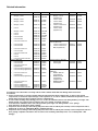
SERVICE MANUAL
BODY
Supplement
LANCER
EVOLUTION VIII
MR
FOREWORD
CONTENTS
This manual contains details of the main changes to
the 2004 model Lancer Evolution VIII MR. Only
differences to the current Lancer Evolution VIII are
included, so please use this manual in conjunction with
the related information specified on the next page.
This information relates to the current vehicle (February
2004). Since specifications will change, some of the
information contained here will inevitably be
superseded.
Note that SI units are used in this manual. Old units are
not shown alongside them.
(However, old units are used for some figures we have
taken from existing documents).
Any opinions, requests, or questions concerning this
manual, should be written on the ‘Servicing
Comments Form’ at the end, and sent to us by fax.
General..........................................
0
Body construction .......................
1
Standard measurements .............
2
Changing welded panels.............
3
Rust treatment..............................
4
Plastics parts................................
5
Body colour ..................................
6
Wiring layout and diagrams ........
7
Reference materials .....................
8
February 2004
MITSUBISHI MOTOR CORPORATION
There are no changes to the shaded chapters,
so they are not included at all in this manual.
This manual is printed on recycled paper.
Related information
Title
New model manuals
•
Mirage, Lancer
No.
Issue date
1036F30
10/1995
•
•
Mirage, Lancer
Mirage, Lancer
1036F31
1036F32
1/1996
8/1996
•
Mirage, Lancer
1036F33
7/1997
•
Lancer
1036F34
1/1998
•
•
•
•
•
•
Mirage, Lancer
Lancer
Lancer
Lancer Sedia
Lancer Sedia
Lancer Evolution VII
1036F35
1036F36
1036F37
1036K30
1036K31
1036K32
10/1998
1/1999
12/1999
5/2000
7/2000
1/2001
•
•
Lancer Sedia
Lancer Sedia
1036K33
1036K34
5/2001
5/2001
•
Lancer Evolution VII
•
Lancer Sedia
•
Lancer Evolution VIII
•
Lancer
•
Lancer
•
Lancer Evolution VIII MR
Service Manuals
•
Lancer Sedia
•
Lancer Sedia
•
Lancer Evolution VII
(supplement)
•
Lancer Sedia (supplement)
•
Lancer Sedia (supplement)
1036K35
1036K36
1036K37
1036K38
1036K39
1036K40
1/2001
5/2002
1/2003
2/2003
12/2003
2/2004
1036K00
1036K01
1036K02
5/2000
7/2000
1/2001
1036K03
1036K04
5/2001
10/2001
Lancer Evolution VII
(supplement)
Lancer Sedia (supplement)
1036K05
1/2002
1036K06
5/2002
Lancer Evolution VII
(supplement)
Lancer (supplement)
Lancer (supplement)
Lancer Evolution VIII MR
1036K07
1/2003
1036K08
1036K09
1036K10
2/2003
12/2003
2/2004
•
•
•
•
•
•
Title
Body Service Manuals
•
Mirage, Lancer
(supplement)
Lancer Sedia
•
•
Lancer Sedia
(supplement)
•
Lancer Evolution VII
(supplement)
•
Lancer Sedia
(supplement)
Wiring layout diagram
Service Manuals
•
Lancer Evolution VIII
•
Lancer Evolution VII
MR (Supplement)
Engine Service Manuals
•
4G6 Engine
•
4G6 Engine
Transmission Service
Manuals
•
W5M51 Manual
Transmission
•
W5M51Manual
transmission
(Supplement)
•
W6MAA Manual
transmission
No.
Issue date
1036F52
8/1996
1036K50
1036K51
5/2000
7/2000
1036K52
5/2001
1036K53
10/2001
1036K77
1036K80
1/2003
2/2004
1039G46
1039G63
1/2001
1/2003
1039M17
1/2001
1039M22
1/2003
1039M23
1/2003
Precautions to be taken when servicing vehicles with seatbelts fitted with SRS Airbag and Pretensioners
Precautions
1. Incorrect inspection or servicing of SRS airbag and pretensioner fitted seatbelt parts, as well as any related
components, could lead to major damage or non-operation as a result of sudden, unintentional operation of SRS
airbag and pretensioner fitted seatbelts (incorrect deployment).
2. In cases where heating from painting processes occurs, the SRS-ECU, driver side airbag module, passenger side
airbag module, pre-tensioner fitted seatbelts, and cross springs, should be removed.
• 93°C and above: SRS-ECU, driver side airbag module, passenger side airbag module, cross springs
• 90°C and above: pretensioner fitted seatbelts
3. Inspections and servicing of SRS airbag and pretensioner fitted seatbelt parts and any related components must,
without fail, be done by a Mitsubishi Motors authorized dealer.
4. Inspections and servicing of SRS airbag and pretensioner fitted seatbelt parts and any related components must be
done paying scrupulous attention to the relevant service manual (particularly in the case of Group 52B – SRS
airbags).
GENERAL - MODEL LINE-UP, APPLIED VEHICLES
0-1
SECTION 0
GENERAL
CONTENTS
Model line-up...........................................0-1
Applied vehicle numbers .......................0-1
Main specifications.................................0-2
Model line-up
Model
Version
’04 Model Grade
GH-CT9A
SNDFZ
¡
RS
SJDFZ
¡
RS
SJGFZ
¡
GSR
Note
¡ = Continued model
Applied vehicles
GH-CT9A: CT9A-0300001 ~
Engine Model
Transmission
Fuel System
4G63
(2 000 DOHC 16 valve
intercooler turbo)
W5M51 (4WD, 5M/T)
MPI
W6MAA (4WD, 6 M/T)
0-2
GENERAL - MAIN SPECIFICATIONS
MAIN SPECIFICATIONS
ITEM
GH-CT9A
SNDFZ
Ordinary
Passenger
vehicle
Saloon
Class
Use
Body
shape
Dimensions
Driving
devices
Vehicle length mm
Vehicle width mm
Vehicle height mm
Distance between axles mm
Distance between
Front
wheels mm
Rear
Minimum ground clearance mm
Interior dimensions
Length
mm
Width
Height
Body overhang mm
Front
Rear
Front
Toe-in mm
wheels
Camber *3
Castor
King pin angle
Rear
Toe-in mm
wheels
Camber
Tyre size
SJDFZ
SJGFZ
4490
1770
1450
2625
1515*1,
1515*1
2
1500*
1515*1,
1515*1
2
1500*
140
1880
1425
1185
825
875
0±2
-1º 00´ ±30´ or -2º 00´ ±30´
3º 55´ ±30´
13º 45´
3 ±2
-1º 00´ ±30´
205/65R15 94H
235/45ZR17
235/45ZR17
Notes
1. *1 in the case of vehicles fitted with 17 inch tyres *2 in the case of vehicles fitted with 15 inch tyres
2. *3 it is possible to select from 3 types of camber. This is be set to -1˚ 00´ ±30´ when shipped from the factory.
BODY CONSTRUCTION – GENERAL, BODY CONSTRUCTION SPECIAL FEATURES 1-1
SECTION 1
BODY CONSTRUCTION
CONTENTS
Summary .................................................1-1
Body construction ..................................1-1
Roof..........................................................1-1
Doors........................................................1-2
Summary
• The roof and side door beams have been changed from steel to aluminium.
Body Construction Special Features
ROOF
Body is now lighter as a result of changing the roof panels to aluminium.
The body is also more rigid now as a result of additional support in pillar areas.
Roof panel
Rear pillar upper support
Centre pillar upper support
Front pillar upper support
a
: shaded areas indicate parts that are the same as those used on current vehicle.
1-2
BODY CONSTRUCTION – BODY CONSTRUCTION SPECIAL FEATURES
DOORS
The body has been lightened as a result of using aluminium for the side door beams.
FRONT DOOR
Front door side door beam
REAR DOOR
Rear door side door beam
a
: shaded areas indicate parts that are the same as those used on current vehicle.
STANDARD DIMENSIONS – GENERAL, B TYPE (straight line measurements)
2-1
SECTION 2
STANDARD DIMENSIONS
CONTENTS
General ....................................................2-1
B type (straight line measurements) ....2-2
Roof..........................................................2-2
General
Together with the changes relating to roof panel replacement, dimensions without the roof in place are specified.
B Type (straight line measurements)
ROOF
units mm
Diagram shows roof assembly removed condition.
Number
Measurement points
Hole shapes – Sizes (mm)
Number
Measurement points
Hole shapes – Sizes (mm)
90
Side roof rail inner corner
-
91
Side roof rail inner corner
-
3-1
CHANGING WELDED PANELS - GENERAL
SECTION 3
CHANGING WELDED PANELS
CONTENTS
Summary .................................................3-1
Body construction ..................................3-2
Aluminium alloy panels..........................3-5
Repairing aluminium alloy panels ........3-5
Painting aluminium alloy panels .........3-10
General
Along with the change to an aluminium roof, important roof replacement details have been specified.
3-2
CHANGING WELDED PANELS – ROOF
Symbol
Operation details
●●●●
Spot welding
■■▲▲
MIG plug welding (
++++
■
: two layers
▲
: three layers)
MIG spot welding
✝✝✝✝✝✝✝✝
MIG arc welding (continuous)
★★★★
Rivet
Areas where rust inhibitor is applied. (Applied using
holes in butt welded locations)
SERVICE JOINTS
Front pillar
upper support
Centre pillar
upper support
Note
❉: these welding points are done by manufacturer (not necessary during repairs).
: black shading indicates areas where structural adhesive is applied.
Adhesive Type
Product name
Epoxy structural adhesive Sumitomo 3M Auto Mix Panel Bond 8115
Rear pillar upper
support
3-3
CHANGING WELDED PANELS – ROOF
(Front pillar upper support
removed condition)
(Rear pillar upper support
removed condition)
IMPORTANT POINTS TO OBSERVE WHEN DOING THE
WORK
REMOVAL
1. When removing the roof, use a support to prevent the side
panels opening out or leaning in.
2. To cut weld the front or rear roof rail, remove the front pillar
upper support and rear pillar upper support.
Self-piercing rivet
Drill
Rivet
Roof panel
Blind rivet
3. Using a drill (∅5mm), make a hole in through the centre of the
rivet, crack it, and remove. Normally, self-piercing rivets are
used, but blind rivets may also be used.
For areas where there is adhesive, use a cold chisel or similar
tool to free and remove the roof.
3-4
CHANGING WELDED PANELS – ROOF
Fitting
appropriate tool
1. Temporarily set the new roof to the body, and drill holes for
rivets with drill (∅5mm).
2. Remove the roof, smooth off any burring around the holes,
then clean the body.
3. Apply structural adhesive to the body side, then fit the roof.
Adhesive Type
Epoxy structural
adhesive
appropriate
tool
part A
flange
rivet
Product name
Sumitomo 3M Auto Mix
Panel Bond 8115
4. Using the appropriate tool, set the rivets as follows:
Rivets: POP rivet SD-62-HR
(1) Insert the rivet into the hole in the base material (roof).
(2) Insert the appropriate tool into Part A of the rivet.
(3) Using the appropriate tool, use the tool handle to press the
rivet flange surface down.
(4) Secure the rivet, snapping at the thin part of A.
Note
In places where setting rivets so that flange makes good
contact is difficult, it is OK to set from inside the vehicle.
Reference:
Appropriate tool (use rivet ∅4.8mm)
Lobster Tools Ltd
Hand riveter: HR-003B
5. When adhesive is dry, remove any excess adhesive then, to
prevent water ingress, apply body sealant to cover entire rivet
area and roof edge.
Roof panel
: black shading indicates body sealant
Product name: Sun Star Penguin Seal 353 (white)
Body sealant
Rivet
3-5
CHANGING WELDED PANELS – ALUMINIUM ALLOY PANELS
ALUMINIUM ALLOY PANELS
Repairing Aluminium Alloy Panels
Precautions when working on sheet metal
1. The main differences to working with sheet steel. (Assuming an ordinary body shop)
Operation
Aluminium alloy panel
Sheet steel
Hammering
Wood or plastic hammer
Sheet steel hammer
Washer welding Not possible
Possible
Gas welding
Workability is poor but possible
Possible
Spot welding
Not possible
Possible
MIG welding
Possible with welder using argon gas and equipment for
aluminium welding
Possible with CO2 gas and normal welding
equipment
2.
3.
4.
5.
At low temperatures, if subjected to a major impact, strength will deteriorate and it will crack.
Coefficient of elasticity is high, so spring-back (force acting to make material regain original form) is high.
Rate of heat transmission is high, and this can cause local thermal expansion.
If overheated, it becomes brittle, and strength deteriorates. If heated further, it will melt without discolouration.
(Heat treatment temperature: approx. 250˚C)
Material
Welding temperature
Aluminium
475˚C~660˚C (varies depending on alloy composition)
Sheet steel
1500˚C~2500˚C
6. Material is soft, so be careful when selecting polish to use.
Also, since polishing powder is light and easily airborne, wear dust mask and goggles.
7. If strong pressure is used when using a disk sander on the alloy, the friction could cause the aluminium alloy to peel off,
and cause clogging.
8. Disk sanders that become clogged will cause deep scratching on aluminium alloy panels, so replace promptly.
9. Do not use general tools or sanders for sanding sheet steel.
(steel fragments or dust will remain on the sander, causing electro-corrosion with other metal)
10. With MIG welding, shield the local area. Sparks, often difficult to see, can be generated and dispersed over a wide area.
Repairing unevenness
This is basically the same as for sheet steel. However, bear in mind
aluminium alloy characteristics when carrying out this work.
1. Repairing sheet metal
(1) Heat with a torch
Note
a. Heat to the point where heat can be felt on the rear side
of panel with hand wearing a glove.
b. Keep torch moving so as not to overheat one area.
CHANGING WELDED PANELS – ALUMINIUM ALLOY PANELS
3-6
(2) When hammering, note that the panels stretch easily, so use a
wooden or plastic hammer.
Note
Reduce stretching and process hardening, and do not
leave hammer marks.
2. Check for distortion
Polish with #80 ~ #120 grade sandpaper, checking for any
distortion.
3. Removing distortions
Remove any distortions Using a levelling hammer and a torch,
correct any distortions.
Note
(1) Heat to about 250˚C to do this work.
(2) Be careful when heating so as not to cause
discolouration when welding.
(3) Use a damp cloth to prevent heat increases which
could result in heat affecting heated area (distortion
etc.)
(4) Do not use drawing hammers which are used for
sheet steel, as this could result in cracking.
4. Polishing
Polish with a disk or a double action sander.
• Disk sander: #100 ~ #120
• Double action sander: #150 ~ #180
Note
Since the material is softer than sheet steel, choose a
polishing material that does not scour the surface deeply.
Repairing cuts and tears
When sheet steel panels are cut, torn, or have holes, repair using
CO2 MIG welding. However, with aluminium alloy panels, use MIG
or TIG welder and use argon gas (inert gas) as shield gas.
Extent of distortion from welding
Gas welding (large distortion) > TIG welding > MIG welding (little
distortion).
Here we explain the MIG welding process, where distortion
resulting from welding is small.
3-7
CHANGING WELDED PANELS – ALUMINIUM ALLOY PANELS
MIG welding procedure
1. Repairing sheet metal
These should be repaired by heating the damaged part gently,
and lightly hammering. The areas stretched by hammering out
should be cut away using an air saw.
Note
(1) Take care not to overstretch or damage the panel.
(2) The gaps at the joint areas should be as narrow as
possible.
2. Welding
This work should be done using equipment designed for
aluminium welding or equipment that can be used for both
aluminium and steel plate welding.
• Welding wire: 5356, 5556, 5183 (JIS classifications)
• Wire dia.: 0.8 or 1.0mm
(1) Remove any grease from welding areas using white spirit
or similar.
(2) Immediately prior to welding, remove any oxidation film
with a stainless steel wire brush (including the rear side), and
carry out the work immediately after cleaning.
Note
To minimize distortion and material melting and coming
away, weld a little at a time, rather than welding long
stretches.
3. Inspecting welded areas
After finishing off areas sanded with #100 disk sander, check
that there are no inadequately welded parts (red check).
Note
The panel surface should not be excessively sanded away.
4. Checking for distortions
Polish with #80 ~ #120 sandpaper, and check for distortion.
5. Removing distortions
Remove any distortions by pressing out using a levelling
hammer and a torch.
Note
(1) Heat to approx. 250˚C to do this work
(2) Take care when heating so that welding can be done
without heating causing any discolouration
CHANGING WELDED PANELS – ALUMINIUM ALLOY PANELS
3-8
(3) Use a damp cloth to prevent temperature rising and
causing distortion or other effects in the area being
heated.
(4) Do not use levelling hammers which are used for sheet
steel as they can cause cracking.
6. Finishing
Finish off with #100~#120 grade disk sander.
Note
As spark marks and carbon adhesion can have an
adverse effect during painting, remove completely using a
stainless steel wire brush.
Other welding
1. TIG welding
The process is basically the same as MIG welding, using the
same arc welder, but instead of using an electrode wire, a rod
coated with flux is used.
To help prevent distortion from the heat generated in welding,
and poor quality welding, this job should be done by someone
with suitable training and practice.
• Welding rod: 5356, 5556, 5183 (JIS classification)
• Diameter: 1.6mm
2. Gas welding (oxyacetylene)
In essence, if gas welding can be done, then a welding rod
and flux (for cleaning and reducing oxide inclusions) can be
used.
To help prevent distortion from the heat generated in welding,
and poor quality welding, this job should be done by someone
with suitable training and practice.
• Welding rod: 5356, 5556, 5183 (JIS classification)
• Diameter: 1.6mm
(1) Flux is made to adhere by heating the welding rod.
3-9
CHANGING WELDED PANELS – ALUMINIUM ALLOY PANELS
(2) Melt the flux with the torch, and weld, removing oxide film.
Note
The molten welding rod flows easily, so as far as possible
keep the surface being welded flat.
(3) Flux left on the panel should be removed using a stainless
steel wire brush or similar.
Finishing filler
1. Polish areas filled with filler using #150 ~ #180 (double action
sander).
2. Clean away any grease on the surfaces where there is filler.
3. Apply 2 part epoxy primer or, for a primer pre-treatment
designed for use with aluminium.
4. Flatten down with # 180 (double action sander)
5. Remove grease and clean surface areas where there is filler.
6. Paint filler in sheet metal, and allow to dry naturally.
Note
Do not speed up by drying at 60˚C or over.
7. Polish with #180.
CHANGING WELDED PANELS – ALUMINIUM ALLOY PANELS
3-10
Painting aluminium panels
Painting on the production line
Same as for painting ordinary steel plate.
Painting for repairs
The main points for repairs in general are as follows.
Paint adhesion to aluminium alloy panels is not quite as good as ordinary steel plate, so pay careful attention to precautionary
notes.
1. Peeling of paint film
Caution: avoid harsh polishing, and try not to generate heat during polishing.
2. Clean and remove any grease
3. Apply wash primer
4. Dry
5. Apply primer surfacer
6. Dry
Note: do not speed up by drying at over 60˚C.
7. Polish
8. Clean, remove any grease
9. Overcoat
10. Dry
Note: do not speed up by drying at over 60˚C.
Remarks:
1. Please refer to paint manufacturer’s instructions for details.
2. Same as for paint repair jobs done on stainless steel plate.
6-1
BODY COLOUR GENERAL, BODY COLOUR LIST, DIFFERENT BODY COLOUR PAINT SECTIONS
SECTION 6
BODY COLOUR
CONTENTS
General ....................................................6-1
Body colour list.......................................6-1
Body colour paint sections ...................6-1
Rear spoiler........................................................6-1
General
This specifies body colour and different body colour paint sections.
Body Colour List
Name of colour
(old colour
name)
Colour symbol
Colour code
Colour (paint)
number
Content of paint Repair symbol
Paint
manufacturer
Cool silver
metallic
CL
A31
CMA10031
Aluminium
M
Kansai Paint
Medium GunMetal grey mica
ES
A39
CMA 10039
Aluminium +
mica
2P
Nippon Paint
Solid White
(Scotia White)
2E
W83
AC10983
-
S
Kansai Paint
Solid Red
(Parma Red)
JW
P85
AC11185
-
S
Kansai Paint
Remarks
1. Repair symbols show only overcoat S: solid M: Metallic 2P: 2 coat pearl.
2. The paint manufacturer’s names are the names used at time of manufacturing.
Different Body Colour Paint Sections
The different rear spoiler paint sections are specified below.
Rear Spoiler
1 Gun metal grey (CMA1002)
2 Part material colour
RJYJ402022–22