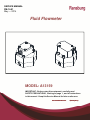
1
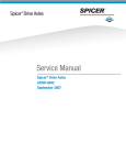
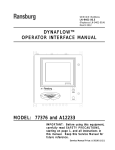
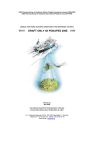
SERVICE MANUAL
FM-14-01
May — 2014
Fluid Flowmeter
MODEL: A13159
IMPORTANT: Before using this equipment, carefully read
SAFETY PRECAUTIONS, starting on page 1, and all instructions
in this manual. Keep this Service Manual for future reference.
Service Manual Price:
$50.00 (U.S.)
A13159 Flowmeter
NOTES
FM-14-01
A13159 Flowmeter - Contents
CONTENTS
SAFETY:
PAGE
1-6
SAFETY PRECAUTIONS.............................................................................................................. 1
HAZARDS / SAFEGUARDS....................................................................................................... 2-6
INTRODUCTION:
7
DESCRIPTION............................................................................................................................... 7
FLOW RATE ACCURACY............................................................................................................. 7
REVERSE FLOW DETECTION .................................................................................................... 7
FLUID PASSAGES ........................................................................................................................ 7
SPECIFICATIONS ......................................................................................................................... 7
INSTALLATION:
8
GENERAL INFORMATION ........................................................................................................... 8
RECEIVER WIRING.. .................................................................................................................... 8
ELECTRICAL NOISE.................................................................................................................... 8
SINGLE VS. DUAL SENSOR INSTALLATIONS .......................................................................... 8
OPERATION:
9
PRINCIPLE OF OPERATION........................................................................................................ 9
AUTOMATIC CLEANING OF THE FLOWMETER ....................................................................... 9
INTRINSICALLY SAFE OPERATION, SINGLE SENSOR ………………………………………. 10
INTRINSICALLY SAFE OPERATION, DUAL SENSOR …………………………………………. 11
MAINTENANCE:
12
CALIBRATION ............................................................................................................................. 12
TROUBLESHOOTING GUIDE .................................................................................................... 12
SERVICING ................................................................................................................................. 12
PARTS:
13
PARTS LIST................................................................................................................................. 13
WARRANTY POLICIES:
14
LIMITED WARRANTY ................................................................................................................. 14
FM-14-01
A13159 Flowmeter - Safety
SAFETY
SAFETY PRECAUTIONS
Before operating, maintaining or servicing any
Ransburg electrostatic coating system, read
and understand all of the technical and safety
literature for your Ransburg products. This
manual contains information that is important
for you to know and understand. This information relates to USER SAFETY and PREVENTING EQUIPMENT PROBLEMS. To help
you recognize this information, we use the following symbols. Please pay particular attention
to these sections.
A WARNING! states information to alert you
to a situation that might cause serious injury if instructions are not followed.
A CAUTION! states information that tells
how to prevent damage to equipment or
how to avoid a situation that might cause
minor injury.
A NOTE is information relevant to the procedure in progress.
While this manual lists standard specifications
and service procedures, some minor deviations may be found between this literature and
your equipment. Differences in local codes and
plant requirements, material delivery requirements, etc., make such variations inevitable.
Compare this manual with your system installation drawings and appropriate Ransburg
equipment manuals to reconcile such differences.
!
WARN ING
The user MUST read and be familiar
with the Safety Section in this manual and
the Ransburg safety literature therein
identified.
This manual MUST be read and thoroughly understood by ALL personnel who
operate, clean or maintain this equipment!
Special care should be taken to ensure that
the WARNINGS and safety requirements
for operating and servicing the equipment
are followed. The user should be aware of
and adhere to ALL local building and fire
codes and ordinances as well as NFPA-33
SAFETY STANDARD, LATEST EDITION,
prior to installing, operating, and/or servicing this equipment.
!
WARN ING
The hazards shown on the following
pages may occur during the normal use
of this equipment. Please read the hazard chart beginning on page 2.
Careful study and continued use of this manual
will provide a better understanding of the
equipment and process, resulting in more efficient operation, longer trouble-free service and
faster, easier troubleshooting. If you do not
have the manuals and safety literature for your
Ransburg system, contact your local
Ransburg representative or Ransburg.
1
FM-14-01
A13159 Flowmeter - Safety
AREA
HAZARD
SAFEGUARDS
Tells where hazards may occur.
Tells what the hazard is.
Tells how to avoid the hazard.
Spray Area
Fire Hazard
Fire extinguishing equipment must be present in
the spray area and tested periodically.
Improper or inadequate operation and maintenance proce- Spray areas must be kept clean to prevent the accumulation of combustible residues.
dures will cause a fire hazard.
Protection against inadvertent Smoking must never be allowed in the spray area.
arcing that is capable of causing The high voltage supplied to the atomizer must be
fire or explosion is lost if any turned off prior to cleaning, flushing or maintesafety interlocks are disabled nance.
during operation. Frequent Power Supply or Controller shut- When using solvents for cleaning:
down indicates a problem in the • Those used for equipment flushing should
system requiring correction.
have flash points equal to or higher than those
of the coating material.
•
Those solvents used for general cleaning must
have a flash point at minimum of 5°C (9°F)
greater than the ambient temperature. It is the
end users responsibility to insure this condition
is met.
•
Spray booth ventilation must be kept at the
rates required by NFPA-33, OSHA, country,
and local codes. In addition, ventilation must
be maintained during cleaning operations
using flammable or combustible solvents.
Electrostatic arcing must be prevented.
Safe
sparking distance must be maintained between the
parts being coated and the applicator. A distance
of 1 inch for every 10KV of output voltage is required at all times.
Test only in areas free of combustible material.
Testing may require high voltage to be on, but only
as instructed.
Non-factory replacement parts or unauthorized
equipment modifications may cause fire or injury.
If used, the key switch bypass is intended for use
only during setup operations. Production should
never be done with safety interlocks disabled.
Never use equipment intended for use in waterborne installations to spray solvent based materials.
The paint process and equipment should be set up
and operated in accordance with NFPA-33, NEC,
OSHA, local, country, and European Health and
Safety Norms.
FM-14-01
2
A13159 Flowmeter - Safety
AREA
HAZARD
SAFEGUARDS
Tells where hazards may occur.
Tells what the hazard is.
Tells how to avoid the hazard.
Spray Area
Explosion Hazard
Electrostatic arcing must be prevented. Safe
Improper or inadequate opera- sparking distance must be maintained between the
tion and maintenance proce- parts being coated and the applicator. A distance
dures will cause a fire hazard.
of 1 inch for every 10KV of output voltage is reProtection against inadvertent quired at all times.
arcing that is capable of causing
fire or explosion is lost if any Unless specifically approved for use in hazardous
safety interlocks are disabled locations, all electrical equipment must be located
outside Class I or II, Division 1 or 2 hazardous
during operation.
areas, in accordance with NFPA-33.
Frequent Power Supply or Controller shutdown indicates a Test only in areas free of flammable or combusproblem in the system requiring tible materials.
correction.
The current overload sensitivity (if equipped)
MUST be set as described in the corresponding
section of the equipment manual. Protection
against inadvertent arcing that is capable of
causing fire or explosion is lost if the current overload sensitivity is not properly set. Frequent
power supply shutdown indicates a problem in the
system which requires correction.
Always turn the control panel power off prior to
flushing, cleaning, or working on spray system
equipment.
Before turning high voltage on, make sure no objects are within the safe sparking distance.
Ensure that the control panel is interlocked with the
ventilation system and conveyor in accordance
with NFPA-33, EN 50176.
Have fire extinguishing equipment readily available
and tested periodically.
General Use and
Maintenance
Improper operation or mainte- Personnel must be given training in accordance
nance may create a hazard.
with the requirements of NFPA-33, EN 60079-0.
Personnel must be properly Instructions and safety precautions must be read
trained in the use of this equip- and understood prior to using this equipment.
ment.
Comply with appropriate local, state, and national
codes governing ventilation, fire protection, operation maintenance, and housekeeping. Reference
OSHA, NFPA-33, EN Norms and your insurance
company requirements.
3
FM-14-01
A13159 Flowmeter - Safety
AREA
HAZARD
SAFEGUARDS
Tells where hazards may occur.
Tells what the hazard is.
Tells how to avoid the hazard.
Spray Area / High Electrical Discharge
Voltage Equipment
There is a high voltage device
Parts being sprayed and operators in the spray
area must be properly grounded.
that can induce an electrical
charge on ungrounded objects
Parts being sprayed must be supported on conveywhich is capable of igniting coat- ors or hangers that are properly grounded. The
ing materials.
resistance between the part and earth ground must
not exceed 1 meg ohm. (Refer to NFPA-33.)
Inadequate grounding will cause
a spark hazard. A spark can
Operators must be grounded. Rubber soled insuignite many coating materials
lating shoes should not be worn. Grounding straps
and cause a fire or explosion.
on wrists or legs may be used to assure adequate
ground contact.
Operators must not be wearing or carrying any
ungrounded metal objects.
When using an electrostatic handgun, operators
must assure contact with the handle of the applicator via conductive gloves or gloves with the palm
section cut out.
NOTE: REFER TO NFPA-33 OR SPECIFIC
COUNTRY SAFETY CODES REGARDING
PROPER OPERATOR GROUNDING.
All electrically conductive objects in the spray area,
with the exception of those objects required by the
process to be at high voltage, must be grounded.
Grounded conductive flooring must be provided in
the spray area.
Always turn off the power supply prior to flushing,
cleaning, or working on spray system equipment.
Unless specifically approved for use in hazardous
locations, all electrical equipment must be located
outside Class I or II, Division 1 or 2 hazardous
areas, in accordance with NFPA-33.
FM-14-01
4
A13159 Flowmeter - Safety
AREA
HAZARD
SAFEGUARDS
Tells where hazards may occur.
Tells what the hazard is.
Tells how to avoid the hazard.
Electrical
Equipment
Electrical Discharge
High voltage equipment is utilized in the process. Arcing in
the vicinity of flammable or
combustible materials may occur. Personnel are exposed to
high voltage during operation
and maintenance.
Unless specifically approved for use in hazardous
locations, the power supply, control cabinet, and all
other electrical equipment must be located outside
Class I or II, Division 1 and 2 hazardous areas in
accordance with NFPA-33 and EN 50176.
Turn the power supply OFF before working on the
Protection against inadvertent equipment.
arcing that may cause a fire or
explosion is lost if safety circuits Test only in areas free of flammable or combustible material.
are disabled during operation.
Frequent power supply shut- Testing may require high voltage to be on, but only
down indicates a problem in the as instructed.
system which requires correcProduction should never be done with the safety
tion.
circuits disabled.
An electrical arc can ignite coating materials and cause a fire or Before turning the high voltage on, make sure no
objects are within the sparking distance.
explosion.
Toxic Substances
Chemical Hazard
Certain materials may be harmful if inhaled, or if there is contact with the skin.
Follow the requirements of the Material Safety
Data Sheet supplied by coating material manufacturer.
Adequate exhaust must be provided to keep the
air free of accumulations of toxic materials.
Use a mask or respirator whenever there is a
chance of inhaling sprayed materials. The mask
must be compatible with the material being
sprayed and its concentration. Equipment must be
as prescribed by an industrial hygienist or safety
expert, and be NIOSH approved.
5
FM-14-01
A13159 Flowmeter - Safety
AREA
HAZARD
SAFEGUARDS
Tells where hazards may occur.
Tells what the hazard is.
Tells how to avoid the hazard.
Spray Area
Explosion Hazard—
Incompatible Materials
Halogenated hydrocarbon solvents for example: methylene
chloride and 1,1,1,Trichloroethane are not chemically compatible with the aluminum that might be used in many
system components. The
chemical reaction caused by
these solvents reacting with aluminum can become violent and
lead to an equipment explosion.
FM-14-01
Aluminum is widely used in other spray application
equipment - such as material pumps, regulators,
triggering valves, etc. Halogenated hydrocarbon
solvents must never be used with aluminum equipment during spraying, flushing, or cleaning. Read
the label or data sheet for the material you intend
to spray. If in doubt as to whether or not a coating
or cleaning material is compatible, contact your
coating supplier. Any other type of solvent may be
used with aluminum equipment.
6
A13159 Flowmeter - Introduction
INTRODUCTION
GENERAL DESCRIPTION
The A13159 Flowmeter has been developed
for precise metering and monitoring of fluid
flows. The flowmeter in many cases surpasses the performance of meters currently used.
SPECIFICATIONS
.01 - 1.00 GPM
(40 mL/min — 4000 mL/min)
Flow Rate:
+/- 3% - 5%
(system dependent)
Accuracy:
FLOW RATE ACCURACY
High flow rate accuracies of 0.5% are achievable with many fluids if the flowmeters are
calibrated at or near the expected flow rates.
Even with wide flow rate swings (such as
when used with robots under analog control)
accuracies of +/- 3% are achievable.
REVERSE FLOW
DETECTION
Dual output, quadrature type sensors are
available, which allows reverse flow detection,
if necessary.
Temperature:
250 psi (17 bar)
MWP @ 100˚F
150˚F (65˚C)
30,000 PPG (8100 PPL)
Single Channel (Standard)
2 Channel Quadrature (Optional)
Fiberoptic (Optional)
Signal Output:
Power:
8-24 VDC
Materials:
Body:
303 Stainless Steel
Gears:
DIN 1.4122
Stainless Steel
(Hardened)
Bushings:
Tungsten Carbide
Shafts:
Tungsten Carbide
Seal:
PTFE
WATER-BASED APPLICATIONS
Filtration:
100 Mesh (maximum)
This Flowmeter is available in a fiberoptic
version for water-based, high voltage, conductive applications. Also, special tin-coated
gears are available (A12715-01) to minimize
corrosion and rust issues.
Connections:
Threaded 3/8” AN (F)
Weight:
4.8 lbs. (2.18 Kg)
FLUID PASSAGES
The Flowmeter requires 3/8” AN male fittings.
This style fitting eliminates flow “dead space”
and also eliminates the need for specially
designed fittings or adhesive inserts. By
creating a streamline fluid passage, color
change time of the meter is improved.
7
Working Pressure:
FM-14-01
A13159 Flowmeter - Installation
INSTALLATION
GENERAL INFORMATION
ELECTRICAL NOISE
The unit may be mounted using the bolt
pattern shown in Figure 1. (2) 1/4 - 28 bolts
should be used. Always mount the flowmeter with the gear faces perpendicular to
the horizon of the earth (i.e. vertical). This
minimizes the effect of gravity on the gears.
The direction of flow must be plumbed as
marked on the side label of the meter. The
fluid inlet is opposite the sensor connection.
All flowmeter cable assemblies employed in
all Binks and Ransburg products use
shielded, twisted-pair cable and are, therefore, designed to minimize noise interference with the flowmeter signals. These
cables cannot, however, eliminate all
spurious noise signals.
Although not absolutely necessary, the
meter should be plumbed such that the flow
enters at the bottom of the meter and exits
at the top. This eliminates any possibility of
air entrapment in the meter.
!
WARN ING
It is important during installation to insure that the flowmeter cables are not run
near (within 12”) noise generating devices
such as large electric motors, fluorescent
lighting, transformers, ballasts, etc.
SINGLE vs. DUAL SENSOR
INSTALLATIONS
Figure 1: Mounting Holes
When single sensor flowmeters are used,
reverse flow detection is not possible.
When employing single sensor flowmeters
on products such as Ransburg’s DynaFlow
System or RansFlow System, it is necessary to jumper the unused gate signal
inputs to the +24 VDC supply. Refer to the
user’s manual for the specific system the
flowmeter is being installed on for complete
details on how and where to add these
jumpers. (Note: The fiberoptic version of
this flowmeter is a single sensor meter.)
!
Figure 2: Receiver Wiring
FM-14-01
WARN ING
This meter may be installed in Class I,
Division I, Group D locations when used
in conjunction with the proper Zener
Barriers. Refer to pages 10 and 11 for
complete connection details.
8
A13159 Flowmeter - Operation
OPERATION
PRINCIPLE OF OPERATION
Gear-type flowmeters work on the principle
that a small volume of material is trapped
between each set of gear teeth and as the
gears rotate, one or two proximity sensors
detect the passing of each of those gear
teeth. Every time one of those gear teeth
passes a proximity sensor, the sensor
sends a square wave pulse back to the
controller, indicating that one of those
cavities of material has passed through the
meter. Flowmeters are typically calibrated
by counting the number of pulses that occur
when one liter of material has passed
through the meter. That value is typically
called the calibration value or calibration
factor and is expressed in pulses per liter
(ppl). Although intuitively one might think
that this value would not change from
material to material, that is not the case, as
it changes based on several factors. These
factors include (but are not necessarily
limited to) viscosity, flow rate, temperature
of the material, percent of solids, lubricity of
the material, solvent vs. water based, and
whether or not the material is thixotropic or
not. It is, therefore, important that geartype flowmeters be calibrated with the
material they are going to be subjected to
for production and at the flow rates expected during production.
AUTOMATIC CLEANING
OF THE FLOWMETER
Fluid Line Air Purges
Air purges are often used in automatic coating
operations for rapid color changes and to
minimize the amount of solvent required to
flush out the old color. Special considerations
must be made when using air purges through
the flowmeter.
1. Lengthy air purges do not provide the
lubrication the flowmeter gears require.
Lubrication is normally provided by the
metered fluid or solvent.
2. Air purges can cause some coating
materials to “dry” on the flowmeter shafts
and gears thus affecting the performance
characteristics of the flowmeter, especially
when water-based materials are used.
3. Excessively long air purges will cause
premature gear and shaft failure.
4. All clean cycles should begin with a
solvent push to prevent drying of coating
material on flowmeter parts.
5. Solvent and air “chop” cycles are recommended as the most efficient way of
flushing flowmeters.
6. On plural-component materials or other
materials that cause a ’skinning’ effect on
the inside of the fluid lines, it is recommended that the fluid lines be left filled
with non-pressurized solvent during idle
times. The system should then be flushed
prior to loading for the next spray cycle.
7. Air purges are not recommended in waterbased applications.
9
FM-14-01
A13159 Flowmeter - Operation
INTRINSICALLY SAFE OPERATION
In order to operate the flowmeter in hazardous areas (Class I, Division I, Group D locations), it is
necessary to run the power going out to the flowmeter and the signal (or signals) returning from the
flowmeter sensor through the approved zener barrier.
Hazardous Area
Non Hazardous Area
Cable must be sealed off
at booth wall according to
local electri cal code requirements.
2 4 VDC
P owe r Su ppl y
A13632-00
(P &F Op ti on)
A1 32 56- 01
Se nso r
772 20 o r
simila r
ca ble
a ssembl y
1
8
2
7
3
6
4
5
Grounded DIN Rail
Single Sensor
P&F Barriers
Hazardous Area
Non Hazardous Area
Cable must be sealed off
at booth wall according to
local electri cal code requirements.
A1 32 56- 01
Se nso r
2 4 VDC
P owe r Su ppl y
A 13 63 2-0 0
(S tah l Optio n)
3
1
4
2
772 20 o r
simila r
ca ble
a ssembl y
Grounded DIN Rail
Single Sensor
Stahl Barriers
Hazardous Area
Non Hazardous Area
Cable must be sealed off
at booth wall according to
local electri cal code requirements.
A1 32 56- 01
Se nso r
2 4 VDC
P owe r Su ppl y
A 13 63 2-0 0
(Tu rck Op ti on)
3
1
4
2
772 20 o r
simila r
ca ble
a ssembl y
Grounded Terminal Block
Grounded DIN Rail
Single Sensor
Turck Barriers
FM-14-01
10
A13159 Flowmeter - Operation
INTRINSICALLY SAFE OPERATION
Hazardous Area
Non Hazardous Area
Ca ble mu st be sealed o ff
at b ooth wall accord ing to
local e le ct rical co de require ments.
A13256-02
Sensor
77220 or
similar
cable
assembly
24 VDC
Pow er Supply
A13633-00
(P&F Option)
1
8
2
7
3
6
4
5
Gro unded DIN Ra il
Dual Sensor
P&F Barriers
A13634-00
(P&F Option)
1
8
2
7
3
6
4
5
Gro unded DIN Ra il
Hazardous Area
Non Hazardous Area
Ca ble mu st be sealed o ff
at b ooth wall accord ing to
local e le ct rical co de require ments.
A13256-02
Sensor
77220 or
similar
cable
assembly
24 VDC
Pow er Supply
A13633-00
(Stahl Option)
3
1
4
2
Gro unded DIN Ra il
A13634-00
(Stahl Option)
Dual Sensor
Stahl Barriers
3
1
4
2
Gro unded DIN Ra il
Hazardous Area
Non Hazardous Area
24 VDC
Pow er Supply
Ca ble mu st be sealed o ff
at b ooth wall accord ing to
local e le ct rical co de require ments.
A13256-02
Sensor
77220 or
similar
cable
assembly
A13633-00
(Turck Option)
3
1
4
2
Grou nded DIN Rail
Ground ed Termin al Blo ck
Dual Sensor
Turck Barriers
A13634-00
(Turck Option)
4
1
5
2
11
7
10
8
9
11
12
FM-14-01
A13159 Flowmeter - Maintenance
MAINTENANCE
CALIBRATION
The calibration value (in pulses per liter or
PPL) will vary based on viscosity, flow rate,
temperature, and other factors. Refer to
appropriate associated equipment for calibration procedure.
the top of the bolts with a soft mallet, while
holding the top half of the body. Clean and
replace worn parts as necessary. Install new
gasket. Install all parts in the order they were
removed. Install flatted portion of shafts
toward gears (see Fig. 4). Push the two
covers together, aligning the pins and holes
by hand.
TROUBLESHOOTING
Flowmeter problems can be caused by
improperly filtered fluid. Particulates in the
fluid can cause gear binding, resulting in
improper signals for the actual flow rate.
Maintain the fluid filters according to the
instructions from the filter manufacturer. If
repeated disassembly and cleaning for removal of solids and particulates occurs, inspect the
entire fluid supply system and evaluate the
system cleaning cycle.
Fluid back-up, that is, reverse flow, can cause
reacted/catalyzed material to enter the flowmeter. Reverse flow will be detected by the 2K
controls and the system will shut down, if
quadrature sensors are used. The flowmeter
should be cleaned immediately, before the
fluid sets-up.
Under normal operation the sensors or electrical connections will not require replacement.
SERVICING
If flow appears blocked or the electronics fails
to see pulses while flow is occurring, follow the
procedure below to disassemble the meter.
Disconnect sensor cable from the flowmeter
sensor. Remove meter for service to a suitable
clean area to perform maintenance. Using a
5mm Allen wrench, remove all 4 bolts. Pull the
sensor section STRAIGHT apart from the gear
pocket section. If the body halves do not slide
apart easily, DO NOT pry them apart with
screwdrivers, etc. Rather, replace the bolts
and only thread them in a few turns, then tap
FM-14-01
Figure 3: Views of Flowmeter Body
It may be necessary to tap the two halves of
the flowmeter together with a soft mallet. DO
NOT use the bolts to pull them together as it
may damage the alignment pins. Snug all
screws down. Tighten the screws in the sequence pattern shown in Fig. 3 to 13 lbs.• ft.
torque. This is a cross pattern to insure proper
gasket sealing.
Figure 4: View of Flatted Portion of Shaft
12
A13159 Flowmeter - Parts
A13159 Hexagon Flowmeter Parts List
Item #
Part #
Description
1
77217-00
Connector (only) [for use only with A13159-01/02]
77220-XX
Flowmeter Cable Assembly (incl. connectors) [A13159-01/02 only]
2
A12768-XX
Fiber Optic Cable Assembly [A13159-03 only]
3
A13256-01
Sensor, Forward Sensing Only
4
A13256-02
Sensor, Bi-directional (forward and reverse sensing)
5
A12719-00
Fiber Optic Transmitter, Forward Sensing Only
6
7
N/A
Upper Housing, Hexagon Flowmeter
8
A12716-00
Shaft, Flowmeter
A12715-00
Gear, Flowmeter (Std.)
10
A12715-01
A13161-00
Gear, Special Tin Coated (Optional)
Gasket, Hexagon Flowmeter *
11
N/A
Lower Housing, Hexagon Flowmeter
12
A12720-00
Fiberoptic Receiver [A13159-03 only]
9
13
SHCS S.S. M6x30mm
* NOTE: The flowmeters are shipped from the factory with white PTFE O-rings. Replacement O-rings will be !nted
blue to indicate that they are metric, for use in the A13159, A12712, and A12713 flowmeters.
FM-14-01
A13159 Flowmeter - Warranty Policies
WARRANTY POLICIES
LIMITED WARRANTY
Ransburg will replace or repair without charge
any part and/or equipment that falls within the
specified time (see below) because of faulty
workmanship or material, provided that the
equipment has been used and maintained in
accordance with Ransburg's written safety and
operating instructions, and has been used
under normal operating conditions. Normal
wear items are excluded.
THE USE OF OTHER THAN RANSBURG
APPROVED PARTS, VOID ALL WARRANTIES.
SPARE PARTS: One hundred and eighty (180)
days from date of purchase, except for rebuilt
parts (any part number ending in "R") for which
the warranty period is ninety (90) days.
EQUIPMENT: When purchased as a complete
unit, (i.e., guns, power supplies, control units,
etc.), is one (1) year from date of purchase.
RANSBURG'S
ONLY
OBLIGATION
UNDER THIS WARRANTY IS TO REPLACE PARTS THAT HAVE FAILED
BECAUSE OF FAULTY WORKMANSHIP
OR MATER-IALS. THERE ARE NO
IMPLIED WAR-RANTIES NOR WARRANTIES OF EITHER MERCHANTABILITY OR
FITNESS FOR A PARTICULAR PURPOSE.
RANSBURG ASSUMES NO LIABILITY
FOR INJURY, DAMAGE TO PROPERTY
OR FOR CONSEQUENTIAL DAMAGES
FOR LOSS OF GOODWILL OR PRODUCTION OR INCOME, WHICH RESULT FROM
USE OR MISUSE OF THE EQUIPMENT BY
PURCHASER OR OTHERS.
EXCLUSIONS:
If, in Ransburg's opinion the warranty item in
question, or other items damaged by this
part was improperly installed, operated or
maintained, Ransburg will assume no
responsibility for repair or replacement of the
item or items. The purchaser, therefore will
assume all responsibility for any cost of
repair or replacement and service related
costs if applicable.
WRAPPING THE APPLICATOR, ASSOCIATED VALVES AND TUBING, AND
SUPPORTING HARDWARE IN PLASTIC,
SHRINK-WRAP, OR ANY OTHER NONAPPROVED COVERING, WILL VOID THIS
WARRANTY.
FM-14-01
14
Manufacturing
1910 North Wayne Street
Angola, Indiana 46703-9100
Telephone: 260-665-8800
Fax: 260-665-8516
Technical Service — Assistance
320 Philips Ave.
Toledo, Ohio 43612-1493
Telephone (toll free): 800-233-3366
Fax: 419-470-2233
www.ransburg.com
Technical Support Representative will direct you to the appropriate telephone number for ordering Spare Parts.
© 2014 Finishing Brands, Americas..
Models and specifications subject to change without notice.
Form No. LN-14-01
Litho in U.S.A.
05/14