1
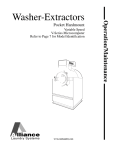
The Chamberlain Group, Inc.
845 Larch Avenue
Elmhurst, Illinois 60126-1196
www.liftmaster.com
Radio
Receiver
Included
Model MSWDCBB
(MEGA SWING UL)
1/2 HP COMMERCIAL DUTY SWING GATE OPERATOR
OWNER’S SERVICE MANUAL
THIS UNIT IS A CLASS 1, 2, 3, OR 4 SWING GATE OPERATOR FOR USE IN SWING GATE APPLICATIONS
TA B L E O F C O N T E N T S
INTRODUCTION
INTRODUCTION
Carton Inventory . . . . . . . . . . . . . . . . . . . . . . . . . . . . . . . . . . .3
Manual Release . . . . . . . . . . . . . . . . . . . . . . . . . . . . . . . . . . . .3
UL325 Model Classifications . . . . . . . . . . . . . . . . . . . . . . . . . .4
Safety Installation Information . . . . . . . . . . . . . . . . . . . . . . . . .5
Safety Precautions for Swing and Ornamental
“Grill Type Gates” . . . . . . . . . . . . . . . . . . . . . . . . . . . . . . . . . .6
Warning Sign Placement . . . . . . . . . . . . . . . . . . . . . . . . . . . . .6
Recommended Photo Cell Layout
for Secondary Entrapment Protection . . . . . . . . . . . . . . . . . . .7
Operator Overview . . . . . . . . . . . . . . . . . . . . . . . . . . . . . . . . . .8
ACCESSORIES
21
SAFETY ACCESSORIES FOR SECONDARY
ENTRAPMENT PROTECTION
21
WARRANTY
22
REPAIR PARTS AND SERVICE
23
INSTALLATION CHECK OFF LIST
24
INSTALLATION
Concrete Pad . . . . . . . . . . . . . . . . . . . . . . . . . . . . . . . . . . . . . .9
Anchors . . . . . . . . . . . . . . . . . . . . . . . . . . . . . . . . . . . . . . . . . .9
Conduits . . . . . . . . . . . . . . . . . . . . . . . . . . . . . . . . . . . . . . . . .9
Safety Edge Installation . . . . . . . . . . . . . . . . . . . . . . . . . . . . . .9
Drive Arm Adjustments . . . . . . . . . . . . . . . . . . . . . . . . . . . . . .9
WIRING AND HOOKUP
AC Power Hookup (120/230 Vac) . . . . . . . . . . . . . . . . . . . . .10
Input Commands Connections . . . . . . . . . . . . . . . . . . . . . . .11
Accessory Connections . . . . . . . . . . . . . . . . . . . . . . . . . . . . .12
Battery Installation . . . . . . . . . . . . . . . . . . . . . . . . . . . . . . . . .12
Master/Second Wiring . . . . . . . . . . . . . . . . . . . . . . . . . . . . . .12
TIMERS AND MODE SELECTIONS S1 & S2
Fast Run Timer - Switch Pack S1 (1-5) . . . . . . . . . . . . . . . . .13
Mode Selections - Switch Pack S1 (6-8) . . . . . . . . . . . . . . . .13
Close Timer - Switch Pack S2 (1-5) . . . . . . . . . . . . . . . . . . .13
Mode Selections - Switch Pack S2 (6-8) . . . . . . . . . . . . . . . .13
IMPORTANT NOTES
• BEFORE attempting to install, operate or maintain the operator,
you MUST read and fully understand this manual and follow all
safety instructions.
• DO NOT attempt repair or service of your commercial door and
gate operator unless you are an Authorized Service Technician.
ADJUSTMENTS
Right or Left Hand Operation . . . . . . . . . . . . . . . . . . . . . . . . .14
Limit Switch Adjustments . . . . . . . . . . . . . . . . . . . . . . . . . . .14
Instant Reverse Device (IRD) . . . . . . . . . . . . . . . . . . . . . . . .14
INSTALL THE RECEIVER
WARNING
Set Security Mode . . . . . . . . . . . . . . . . . . . . . . . . . . . . . . . . .15
Programming the Remote to the Receiver . . . . . . . . . . . . . .15
To Erase All Remote Control Codes . . . . . . . . . . . . . . . . . . . .15
Mechanical
CAUTION
WARNING
WARNING
Electrical
WARNING
CAUTION
MAINTENANCE
General Service . . . . . . . . . . . . . . . . . . . . . . . . . . . . . . . . . . .16
Battery Disposal . . . . . . . . . . . . . . . . . . . . . . . . . . . . . . . . . . .16
Battery Replacement . . . . . . . . . . . . . . . . . . . . . . . . . . . . . . .16
Battery Maintenance/Testing . . . . . . . . . . . . . . . . . . . . . . . . .16
Battery Handling/Storage . . . . . . . . . . . . . . . . . . . . . . . . . . . .16
WARNING
CAUTION
TROUBLESHOOTING
Battery Checkout . . . . . . . . . . . . . . . . . . . . . . . . . . . . . . . . . .17
Gate Not Operating . . . . . . . . . . . . . . . . . . . . . . . . . . . . . . . .17
SUGGESTED LOOP SENSOR LOCATIONS
When you see these Safety Symbols and Signal Words on the
following pages, they will alert you to the possibility of SERIOUS
INJURY or DEATH if you do not comply with the warnings that
accompany them. The hazard may come from something
mechanical or from electric shock. Read the warnings carefully.
When you see this Signal Word on the following pages, it will
alert you to the possibility of damage to your gate and/or the gate
operator if you do not comply with the cautionary statements that
accompany it. Read them carefully.
Free Exit on Vehicle Approach . . . . . . . . . . . . . . . . . . . . . . . .18
Entry With Access Control Device . . . . . . . . . . . . . . . . . . . . .18
Dual Direction as Entry and Free Exit . . . . . . . . . . . . . . . . . .18
AVERTISSEMENT
CONTROL BOARD LAYOUT
Component Locations . . . . . . . . . . . . . . . . . . . . . . . . . . . . . .19
REPAIR PARTS
AVERTISSEMENT
20
2
ATTENTION
AVERTISSEMENT
AVERTISSEMENT
INTRODUCTION
MANUAL RELEASE
CARTON INVENTORY
To operate gate manually, REMOVE top plastic cover on top of
arm. Locate RED release handle.
1. Extend RED handle forward to provide greater leverage.
2. Once extended, pull up on RED handle to release the clamp on
the shaft.
3. Next, locate release pin (shown below right), press button and
pull out. After you have released the clamp and removed the
pin, gate will be free to move manually.
Before beginning your installation check that all components
were provided and received undamaged. Refer to list below
for factory provided parts.
Description
Operator
Accessory Shelf
Owner’s Manual
Warning Signs
Sealed 12Vdc, 7AH Batteries
Primary Arm Assembly
Emergency Release Pin
2. Pull Back
3. Press Button &
Pull Pin To Release
RED HANDLE
1. Extend
3
Qty.
1
1
1
2
2
1
1
UL325 MODEL CLASSIFICATIONS
The MSWDCBB is intended for use with a vehicular swing gate. The
operator can be used with Class I, Class II, Class III, and Class IV
CLASS I – RESIDENTIAL VEHICULAR GATE OPERATOR
A vehicular gate operator (or system) intended for use in a home of one-to four single family dwellings,
or a garage or parking area associated therewith.
CLASS II – COMMERCIAL/GENERAL ACCESS VEHICULAR GATE OPERATOR
A vehicular gate operator (or system) intended for use in a commercial location or building such as a
multi-family housing unit (five or more single family units) hotel, garage, retail store or other building
servicing the general public.
CLASS III – INDUSTRIAL/LIMITED ACCESS VEHICULAR GATE OPERATOR
A vehicular gate operator (or system) intended for use in a industrial location or building such as a
factory or loading dock area or other location not intended to service the general public.
CLASS IV – RESTRICTED ACCESS VEHICULAR GATE OPERATOR
A vehicular gate operator (or system) intended for use in a guarded industrial location or building such
as an airport security area or other restricted access locations not servicing the general public, in which
unauthorized access is prevented via supervision by security personnel.
UL325 ENTRAPMENT PROTECTION REQUIREMENTS
SAFETY ACCESSORY SELECTION
All UL325 compliant LiftMaster gate operators will accept external
entrapment protection devices to protect people from motorized
gate systems. UL325 requires that the type of entrapment
protection correctly matches each gate application. Below are the
six types of entrapment protection systems recognized by UL325
for use on this operator.
GATE OPERATOR ENTRAPMENT PROTECTION
UL325
Installation
Class
ENTRAPMENT PROTECTION TYPES
Type A: Inherent obstruction sensing system, self-contained
within the operator. This system must sense and initiate
the reverse of the gate within two seconds of contact
with a solid object.
Type B1: Connections provided for a non-contact device, such as
a photoelectric eye can be used as a secondary
protection.
Type B2: Connections provided for a contact sensor. A contact
device such as a gate edge can be used for secondary
protection.
Type C: Inherent adjustable clutch or pressure relief valve.
Type D: Connections provided for a control
requiring continuous pressure to
operate the operator open and close.
Type E: Built-in audio alarm. Examples
include sirens, horns or buzzers.
Moving Gate Can Cause
Injury or Death
NOTE: UL requires that all installations must
KEEP CLEAR! Gate may move at any
time without prior warning.
have warning signs placed in plain view on
Do not let children operate the gate or
play in the gate area.
This entrance is for vehicles only.
both sides of the gate to warn pedestrians of
Pedestrians must use separate entrance
the dangers of motorized gate systems.
Slide Gate Operator
Swing & Gate Barrier
(Arm) Operator
Primary
Type
Secondary
Type
Primary
Type
Secondary
Type
Class
I & II
A
B1, B2
or D
A or C
A, B1, B2,
or C
Class III
A, B1 or
B2
A, B1, B2,
D or E
A, B1, B2
or C
A, B1, B2,
C, D or E
Class IV
A, B1, B2
or D
A, B1, B2,
D or E
A, B1, B2,
C or D
A, B1, B2,
C, D or E
The chart above illustrates the entrapment protection
requirements for each of the four UL325 classes.
In order to complete a proper installation you must satisfy the
entrapment protection chart shown above. That means that
the installation must have one primary means of entrapment
protection and one independent secondary means of
entrapment protection. Both primary and secondary
entrapment protection methods must be designed, arranged
or configured to protect against entrapments in both the open
and close directions of gate travel.
For Example: For a slide gate system that is installed on a
single-family residence (UL325 Class I) you must provide the
following: As your primary type of entrapment protection you
must provide Type A inherent (built into the operator)
entrapment sensing and at least one of the following as your
secondary entrapment protection: Type B1- Non-contact
sensors such as photoelectric eyes, Type B2- Contact sensors
such as gate edges or Type D- Constant pressure control.
4
SAFETY INSTALLATION INFORMATION
1. Vehicular gate systems provide convenience and security. Gate systems are comprised of many component parts. The gate
operator is only one component. Each gate system is specifically designed for an individual application.
2. Gate operating system designers, installers and users must take into account the possible hazards associated with each individual
application. Improperly designed, installed or maintained systems can create risks for the user as well as the bystander. Gate
systems design and installation must reduce public exposure to potential hazards.
3. A gate operator can create high levels of force in its function as a component part of a gate system. Therefore, safety features
must be incorporated into every design. Specific safety features include:
• Gate Edges
• Guards for Exposed Rollers
• Photoelectric Sensors
• Screen Mesh
• Vertical Posts
• Instructional and Precautionary Signage
4. Install the gate operator only when:
a. The operator is appropriate for the construction and the usage class of the gate.
b. All openings of a horizontal slide gate are guarded or screened from the bottom of the gate to a minimum of 4' (1.2 m) above
the ground to prevent a 2 1/4" (6 cm) diameter sphere from passing through the openings anywhere in the gate, and in that
portion of the adjacent fence that the gate covers in the open position.
c. All exposed pinch points are eliminated or guarded, and guarding is supplied for exposed rollers.
5. The operator is intended for installation only on gates used for vehicles. Pedestrians must be supplied with a separate access
opening. The pedestrian access opening shall be designed to promote pedestrian usage. Locate the gate such that persons will not
come in contact with the vehicular gate during the entire path of travel of the vehicular gate.
6. The gate must be installed in a location so that enough clearance is supplied between the gate and adjacent structures when
opening and closing to reduce the risk of entrapment. Swinging gates shall not open into public access areas.
7. The gate must be properly installed and work freely in both directions prior to the installation of the gate operator.
8 Controls intended for user activation must be located at least six feet (6') away from any moving part of the gate and where the
user is prevented from reaching over, under, around or through the gate to operate the controls. Outdoor or easily accessible
controls shall have a security feature to prevent unauthorized use.
9. The Stop and/or Reset (if provided separately) must be located in the line-of-sight of the gate. Activation of the reset control shall
not cause the operator to start.
10. A minimum of two (2) WARNING SIGNS shall be installed, one on each side of the gate where easily visible.
11. For a gate operator utilizing a non-contact sensor:
a. Reference owner’s manual regarding placement of non-contact sensor for each type of application.
b. Care shall be exercised to reduce the risk of nuisance tripping, such as when a vehicle trips the sensor while the gate is still
moving.
c. One or more non-contact sensors shall be located where the risk of entrapment or obstruction exists, such as the perimeter
reachable by a moving gate or barrier.
12. For a gate operator utilizing a contact sensor such as an edge sensor:
a. One or more contact sensors shall be located where the risk of entrapment or obstruction exists, such as at the leading edge,
trailing edge and post mounted both inside and outside of a vehicular horizontal slide gate.
b. One or more contact sensors shall be located at the bottom edge of a vehicular vertical lift gate.
c. A hard wired contact sensor shall be located and its wiring arranged so the communication between the sensor and the gate
operator is not subject to mechanical damage.
d. A wireless contact sensor such as the one that transmits radio frequency (RF) signals to the gate operator for entrapment
protection functions shall be located where the transmission of the signals are not obstructed or impeded by building structures,
natural landscaping or similar obstruction. A wireless contact sensor shall function under the intended end-use conditions.
e. One or more contact sensors shall be located on the inside and outside leading edge of a swing gate. Additionally, if the bottom
edge of a swing gate is greater than 6" (152 mm) above the ground at any point in its arc of travel, one or more contact sensors
shall be located on the bottom edge.
f. One or more contact sensors shall be located at the bottom edge of a vertical barrier (arm).
5
SAFETY PRECAUTIONS FOR SWING AND
ORNAMENTAL "GRILL TYPE GATES"
WARNING
WARNING
To prevent SERIOUS INJURY or DEATH from a moving gate:
• Entrapment protection devices MUST be installed to protect
anyone who may come near a moving gate.
• Locate entrapment protection devices to protect in BOTH the
open and close gate cycles.
• Locate entrapment protection devices to protect between
moving gate and RIGID objects, such as posts.
• A swinging gate shall NOT open into public access ways.
CAUTION
WARNING
AVERTISSEMENT
AVERTISSEMENT
ATTENTION
AVERTISSEMENT
WARNING SIGN PLACEMENT
WARNING
WARNING
To prevent SERIOUS INJURY or DEATH from a moving gate:
• Install warning signs on EACH side of gate in PLAIN VIEW.
• Permanently secure each warning sign in a suitable manner
using fastening holes.
CAUTION
WARNING
ADVERTENCIA
ADVERTENCIA
ADVERTENCIA
PRECAUCIÓN
AVERTISSEMENT
AVERTISSEMENT
Moving Gate Can Cause
Injury or Death
KEEP CLEAR! Gate may move at any
time without prior warning.
Do not let children operate the gate or
play in the gate area.
This entrance is for vehicles only.
Pedestrians must use separate entrance
ATTENTION
AVERTISSEMENT
6
RECOMMENDED PHOTO CELL LAYOUT
FOR SECONDARY ENTRAPMENT PROTECTION
Please use all safety devices on your installation to achieve the
safest operation. (This is a view from above gate.)
(Do Not Allow Any Pinching At Hinge)
Photo Cell
Safety Beam (Note-2 & 3)
MEGA SWING UL
Reflector or
Transmitter
Gate Leaf
Wall or Fence
Closes This
Direction
Drive Arm
Stop Beam
(Note-1)
Example of a Right
Hand Operator
Danger Zone
(Back Area)
Reflector or
Transmitter
Safety Edge
(Note-2 & 3)
This drawing is not to scale.
NOTE-1: (Required) Secondary entrapment device
(use JP2 on control board; UL-325)
NOTE-2: May be added as a third level of safety but is not to
replace beams marked NOTE-1
NOTE-3: Safety edge or beam will re-open a closing gate
(use J5 #5, safety loop input)
NOTE: This unit to employ:
Primary entrapment is an “A1” inherent entrapment sensing
system with an audio alarm (reverses gate direction). Secondary
entrapment is a “B1” a non-contact, photoelectric beam, connect
at JP2 (stops gate, see NOTE-1). Use only UL recognized
sensors. At least one secondary “stop” photo beam should be
installed across and above danger zone to stop the gate operator
should a person enter this area. Photo beams should be installed
according to their manufacturer’s instructions and are to be
placed in areas that pose a risk of entrapment. A separate
pedestrian door is required per UL-325.
On swing gates that use a contact sensor, one or more contact
sensors shall be located on the inside and outside leading edge
of a swing gate. If the gate is greater than 6" above the ground at
any point in its arc of travel, one or more contact edges shall be
located on the bottom edge of the gate.
7
OPERATOR OVERVIEW
The LiftMaster model MEGA SWING UL swing gate operator is unique in the industry. Setting the MEGA SWING UL apart are many
features that make it the front runner in its class. With standard features like:
• Built in battery run - inherent 24VDC backup power with regulated 24VDC for accessories.
• High torque 1/2 HP 24 volt Permanent Magnet DC motor.
• Full service controller with eight inputs and LED indicators for loops, card reader, radio, etc.
• Continuous duty operation for most types of gates.
• Reversible gate direction for right or left handed operation.
• Instant Reverse Device (IRD) monitor senses obstructions going open and close.
• Automatic open of gate when AC power is lost if desired (with 15 second delay selection).
• ANTI-TAIL GATE with QUICK CLOSE feature STOP gate in close travel if tail-gating is sensed
• Upon complete system failure (lightning, surges, etc.) gate can opened by emergency release pin.
• All rust proof aluminum construction with baked on powder coat enamel.
• Molded Polyethylene UV stabilized cover never needs wax or paint.
• Unique Clam-Shell cover design. Cover is removed with out disconnecting the drive arm.
• Double reduction gear reducer eliminates internal chains & gears.
• State of the art MOSFET motor drive technology, NO contactors or relays.
• Dynamic motor braking for precision stopping at open and closed positions.
• Soft start and stop in open and close travel motions.
• Non-Entrapment arm design, arm does not scissor over its self.
• High reliability micro switches actuate through durable limit cams on a precision ground shaft.
• Maximum Run Timer for motor (MRT) with anti-tamper protection in closing direction.
• Each unit configurable as master or second operator.
• Safe 24VDC low voltage motor and control wiring.
• LED diagnostics for easy troubleshooting.
• Closing timer adjustable from 1-31 seconds with on/off selection.
• Transient voltage protection on all inputs.
• Capable of being powered from 120 or 230 Vac, or UL Listed Class 2 Solar Power.
• On 120 Vac installations, unswitched duplex out gives convenient supply for 120 Vac accessories.
• Maximum weight of 650 lbs. Maximum length of 18'. (Free moving operation, NO BINDING)
• 10 year perforation warranty on cover and chassis with 2 years on electronics and mechanism.
• Input for safety edge device to reduce the possibility of entrapment – recommended.
• Input for non-contact sensing device (photo beam) for secondary entrapment protection.
NOTE: If the operator is installed in a region where temperatures regularly go below 30˚ F then it is recommended that the optional
heater is installed. Refer to the accessory page.
8
I N S TA L L AT I O N
CONCRETE PAD
The concrete pad for operator mounting should be approximately
24" deep x 24" wide x 26" long in order to provide adequate
weight and structure to insure proper and stable operation. Pad
should be 6" above finished grade (street level) even with top of
6" curb if one is present. Be sure to position pad so that the
operator mounting bolts are not too close to the edges of the
concrete pad. See drawing on page 3A.
NOTE: Pad must always extend below the frost line in areas
where the ground freezes.
Closing
Direction
MEGA SWING UL
Elbow
22°
Proper angle for drive arm installation,
do not allow arm to scissor.
ANCHORS
Proper anchors for fastening operator to pad will be a 1/2" x 6"
wedge anchor patterned to match the mounting base of the unit.
They should be installed with approximately 1" showing above
concrete surface in order to allow for the 3/8" thick base as well
as washers for any leveling. See drawing on page 3A.
Gate Plate
CONDUITS
The Mega Swing UL is equipped with 1/2 and 3/4 knockout in the
back of the accessory cabinet. It is recommend that the conduits
come up under the outer enclosure. If wiring must be brought in
from outside the enclosure, be sure to follow all required
electrical codes. The conduits may come up any where beneath
the enclosure except under the mounting angles which the unit is
mounted with.
NOTE: Do not attempt to hook up the 120/230 Vac mains if wires
are LIVE or HOT. Be SURE power is off.
Pad 24" Deep
24" Wide
26" Long
Elbow
Pad
DRIVE ARM CONFIGURATION
NOTE: Distance from top of concrete pad to bottom of plate that
mounts on gate is 26.9".
A= Primary Arm: Output shaft pivot point to elbow pivot point.
B= Secondary Arm: Elbow pivot point to gate plate pivot point.
C= Gate hinge pivot point to gate plate pivot point.
D= Gate leaf to output shaft pivot point (as measured while open).
E= Gate hinge pivot point to output shaft pivot point.
F= Where to begin back of pad. It is 9" less than the “E” dimension.
G= Required clearance for (B) secondary arm at full open position.
NOTE: Chart below provides estimates only.
SAFETY EDGE INSTALLATION
It is highly recommended that a pressure sensing edge (safety
edge) be installed at the leading edge and at all hazard and pinch
points of the gate. Choose an edge that will cover the full height
of the gate. It should be installed securely and any coil cord used
to send the signal back to the operator should be cut so that
excess cord be eliminated to prevent it from getting tangled in the
gate or mechanism. Edges that are to REVERSE and re-open a
closing gate connect to J5 #5 and commons #9 - #12. Edges that
are to STOP the gate that is opening or closing will connect to the
2 pins on the JP2 block near the center of the board.
A
B
C
D
E
F
G
31.75"
40.25"
48.0"
14.0"
39.75"
30.75"
44.5"
2
30.5"
37.0"
44.0"
14.0"
40.0"
31.0"
40.0"
3
29.25"
35.5"
43.5"
14.0"
34.0"
25.0"
40.0"
4
28.0"
31.5"
40.5"
14.0"
28.5"
19.5"
36.0"
5
25.5"
24.25"
32.5"
11.5"
26.75"
17.75"
20.5"
1
DRIVE ARM ADJUSTMENTS
To adjust the length of the Primary Arm, you can use any two of
the holes that line up with the two holes in the pivot plate that
mounts to the top of the output shaft. You will need to cut off any
excess material that extends off the back side. Install the two
bolts and tighten them securely.
To adjust the Secondary Arm, there are two set screws under the
ARM ENDS that can be loosened to allow that section to be
adjusted. It may be necessary to cut the aluminum tube to a
shorter length for some installations.
Use Line 5 to get operator into a compacted space (not for
heavy/hard to swing gates).
Arm Ends
Release Pin Hole
Set Screws
Secondary
Arm Tube
9
Primary Arm
ING
W I R I N G WARNING
AND HOOKUP
ON
WARNING
To reduce the risk of SEVERE INJURY or DEATH:
• ANY maintenance to the operator or in the area near the
operator MUST not be performed until disconnecting the
electrical power and locking-out the power via the operator
power switch. Upon completion of maintenance the area
MUST be cleared and secured, at that time the unit may be
returned to service.
• Disconnecting power at the fuse box BEFORE proceeding.
Operator MUST be properly grounded and connected in
accordance with local electrical codes. NOTE: The operator
should be on a separate fused line of adequate capacity.
• ALL electrical connections MUST be made by a qualified
individual.
SEMENT
ON
AVERTISSEMENT
AC POWER HOOKUP (120/230 Vac)
AVERTISSEMENT
Be sure your main power is OFF before attempting to hook up the AC power. The AC wiring should be attached to the wires exiting the
conduit or pedestal post. Only use U.L. approved 14AWG (or larger) 600 volt insulated wire. NOTE: Do not connect any of the AC
power wires directly to the electronic control board. Connect the batteries after the AC power is restored.
230 Vac
Please purchase the 120 to 230 Vac conversion kit for 230 Vac
operation. See Accessory page.
120 Vac
Connect the BLACK wire to the incoming 120 Vac hot lead and
connect the WHITE wire to the incoming neutral lead. Connect the
GREEN wire to the ground.
Duplex
Outlet Box
120 Vac
Hot (Black)
Ground (Green)
ENCIA
CIÓN
• DO NOT install any wiring or attempt to run the operator
without consulting the wiring diagram. We recommend that
you Install an optional reversing edge BEFORE proceeding with
the control station installation.
• ALL power wiring should be on a dedicated circuit and well
protected. The location of the power disconnect should be
visible and clearly labeled.
• ALL power and control wiring MUST be run in separate
conduit.
• BEFORE installing power wiring or control stations be sure to
follow all specifications and warnings described below. Failure
to do so may result in SEVERE INJURY to persons and/or
damage to operator.
1
120 Vac
Neutral (White)
ADVERTENCIA
Ground
Neutral
ADVERTENCIA
10
Terminal 5, Safety - Safety edge(s) and safety loop input. This
function will make the gate reverse and go back to the open
position if it was closing. Input is for all NORMALLY OPEN
contact safety devices. This input is disabled when gate is in
the full closed position. Use with vehicle loops, photo beams
and sensors.
Terminal 6, Close - ANTI-TAIL GATE close input. When using a
vehicle detector, you must use the presence contacts (N.O. and
C.) This input will QUICK close gate after input is applied and
then removed. It will stop the open cycle and reverse gate to
close. (Example: Car crosses over close loop before gate
reaches full open position – gate will reverse and close).
NOTE: The close input also acts as a safety-stop in that if gate
is closing and a tail-gater is sensed at the close input, the gate
WILL STOP its closing motion and not continue to close until
the close input is removed or gate is re-opened.
Terminal 7, Back-Away (For Barrier Arm Gate Only) - This
input is recommended for use with our Mega Arm barrier
gates. For your Mega Slide X, please use terminals 1, 2 or 3 for
your free exit loop input.
Terminal 8, Shadow Loop - This input operates as a hold open
only when gate is a full open position.
Terminals 9, 10, 11, 12 Common - These inputs used for
common (0 VDC) to above listed functions.
NOTE: J5 inputs 1-8 are tied to LED indicators to assist in trouble
shooting.
3-Button Control Station - Not already in place. See diagram
below.
INPUT COMMANDS CONNECTIONS
(Use common and normally open contacts from devices
connected to these inputs)
JP2 Input
This input will stop the gate and activate the siren.
This input is for connection to wired contact edge sensors at
pinch points and photo beams that run along either side the gate
panel when in open position (if dead panel is present one beam
should run along it)
Input Commands - J5 Connector Block at top of Control Board
Control wire connections at low voltage terminal strip will be at
the top of the electronic control board. Make connections to the
appropriate points for the desired operation. Wires should be U.L.
approved 600 volt rated and at least 18 awg. All external control
devices must have normally open dry contacts. DO NOT
CONNECT ANY DEVICE WHICH WOULD DELIVER ANY VOLTAGE
OF ANY KIND TO THESE TERMINALS.
Terminals 9, 10, 11, 12 are the commons (0 VDC) used to
activate the following inputs.
Terminals 1, 2, 3 Open - These inputs will trigger gate open
when pulsed or hold gate open with maintained contact. When
released gate will close if closing timer is on or if close input is
given.
Terminal 4, Auxiliary Open - This is the wired line of sight,
intended manual reset input. Use this input to reset the unit
after a 2nd sequential obstruction is sensed and gate is locked
with siren running. This input normally functions as listed
below.
Acts same as 1, 2, 3 above with S2-6 off. With S2-6 ON this
will operate as a pulse-open, pulse-close.
NOTE: Pulse to close will only work when gate is at full open
position.
SIREN will run for 5 minutes after 2nd sequential obstruction,
then turns itself off, however operator will require a reset signal
to J5 #4 to re-activate gate. In addition, cycling the AC power
will also reset unit.
J5 Input #1
J5 Input #6
Open
Close
Stop
JP2 Connector
(NOTE: Siren Will
Sound When Stop
Button Is Depressed)
J5 Commons #9-12
11
ACCESSORY CONNECTIONS
These terminals will provide battery backed power to 24 VDC
devices and are located at the bottom of the electronic control
board at J4 terminals 1 and 2. Terminal 1 is 24 VDC (+) and
number 2 is 0 VDC (-). Peripheral CLASS 2 low voltage devices
that require 24 VDC power maybe connected here (500 ma.
maximum). EXAMPLE: Vehicle detector, radio receiver.
RELAY OUTPUT K1: For class 1 and 2 installations, do not
disconnect siren. S1-6 must be on and S1-8 must be off.
FIGURE 1
Black Lead
–
BATTERY INSTALLATION
+
12 VDC Battery 7-10 amp
HOOKING UP BATTERY LEADS: Always hookup and turn on AC
power before installing batteries. After turning on AC power,
install two NEW, fully charged 12 volt DC batteries on shelf next
to motor. Connect red lead from operator to the positive (RED +)
terminal of one battery and black lead from the operator to the
(BLACK-) terminal of the OTHER battery. Place a jumper between
the remaining terminals of each battery if one is not already in
place (Figure 1).
Jumper
–
Red Lead
+
12 VDC Battery 7-10 amp
Failure to install batteries correctly will cause damage and will
not be covered by warranty.
MASTER/SECOND WIRING
FIGURE 2
Master/second wire hook up:
1. In a master/second configuration, either unit can be the master.
Choose one unit to be the master and then direct all control
wiring to it (also install vehicle detectors and radio receivers
this unit)
2. At the MASTER, any input (at J5) with control (detectors,
receivers, keypads, timers, etc.) wires to it must also be run to
the same terminals of the second.
Along with these control wires, both operators MUST share a
common ground connection from chassis to chassis (or from
PCB common to PCB common (Ex: master gate J5 terminal
#12 to second gate J5 terminal #12)
EXAMPLE: If only open and close are used at master then three
wires will run between gates (Figure 2). More may be needed
for additional functions to be used.
3. If it is required that if one gate senses an obstruction, the other
reverses also, then 3 additional wires must be run between the
master J3 and second J3 (Figure 3). These connections are for
transmitting IRD (obstruction signals) between both units. This
will allow the master or second to inform the other that a
closing obstruction has occurred and for it to reverse and
open. SET switches on S2, 1-8 the same on both gates.
Master-J5
1
2
3
4
5
6
7
8
9 10 11 12
Common
Close
Open
1
2
3
4
5
6
7
8
9 10 11 12
Second-J5
FIGURE 3
RX GND
1
2
3
TX
4
Master-J3
IRD - Obstruction Signal Connections
Terminal 1 of Master must go to terminal 4
of Second and terminal 1 of Second must
go to terminal 4 of Master. Terminal 2 of
Master must go to terminal 2 of Second.
Second-J3
1
2
3
RX GND
12
4
TX
TIMERS AND MODE SELECTIONS S1 & S2
FAST RUN TIMER - SWITCH PACK S1 (1-5)
To change the FAST SPEED run timer, set the dip switches to add
up to the number of seconds it takes for the swing gate to make a
full open or closed cycle minus 1 second.
Example: If cycle is 15 seconds, then set dip switches to add up
to 14 seconds (dips 2,3,4 are on) which is 2 seconds + 4
seconds + 8 seconds = 14 seconds. Setting FULL SPEED to end
before the end of travel will allow the gate to go to the slow speed
before stopping.
Verify that the FAST SPEED run timer setting slowed down the
gate approximately one foot from the end of travel. If it does not,
adjust the dip switches appropriately.
Seconds - -
S1
1--
2--
4--
8--
16
ON
ON
OFF
ON
OFF
OFF
OFF
OFF
OFF
1 2 3 4 5 6 7 8
Fast Run Timer 1-5
Shows
Default
Settings
Mode Selection 6-8
MODE SELECTIONS - SWITCH PACK S1 (6-8)
6
7
8
CLOSE
R21
R16
OPEN 1 OPEN 2 OPEN 3
R24
C3
R5Ø
U14
R34
R4Ø
R45
R49
R22
R33
R39
R44
R48
R43
R26
R25
C7
DX3
X2
DX4
R56
IRD
D2
C4
U3
R5
CPU
D2Ø
1A DC
R2Ø
R15
+
C5
C2Ø
+
F1
F4
+
B1
R11
HBEAT
K1
D11
BAT LO AC POWER
D12
F3
R13
BAT–
MOTOR
MOV
Aux Relay
TR
C NC NO DC
1
B2
MODE SELECTIONS - SWITCH PACK S2 (6-8)
–
J4
U19
D14
R55
WARNING FOR
R62
CONTINUOUS
PROTECTION
AGAINST FIRE
DX1
REPLACE ONLY
WITH THE SAME
TYPE AND RATING
OF FUSE
C8
D25
D26
D1
R2
R51
Q4
D28
R3
Q1
D9
R37
F2
R19
R4
DX2
R38
JP2
U2
D29
R57
C13
R6
J1
Q6
Q5
C6
U1Ø
CLS
D3
On the MEGA SWING UL the switches 1-5 on S2 are for the
closing timer delay. If S2-7 is on, the gate will auto close by
timer. Default is S2-3 “on” to provide a 4 second delay if
activated.
U16
R58
C12
U12
U7
R7
R59
D27
U5
CLOSE
D4
R6Ø
R63
D21
IRD1
R8
R43
C16
R61
U15
C19
C1
R46
U13
R23
U6
R9
BRAKE
D5
CLOSE TIMER - SWITCH PACK S2 (1-5)
X1
R1Ø
D6
U11
C22
OLS
D7
OPEN
R41
U9
F5
C2
C2
U1
R35
U8
U4
T8
T7
AUX 4 SAFETY 5 CLOSE 6 BACK 7SHADOW 8
D24
5
R12
D23
4
1Ø 11 12
D22
3
9
R53
2
8
D19
R17
1
7
R47
R18
S2
8
D18
7
6
R42
6
5
T6
T5
D17
5
D16
4
R36
3
4
T4
T3
T2
T1
D15
2
S3
R3Ø
D1Ø
1
3
R14
U18
D8
S1
2
J5
Q2 OPEN
J3
M/S
R1
1
MANUAL
1
AUX LIMITS
C15
1
J2
C18
SWITCH 6: FAIL SECURE MODE, (VER 6.351 or higher) with
AC power off, in continuous battery back up mode (S2 #8 off)
gate will not auto open if batteries get low. If batteries are low,
gate will stay open after an open command is given.
SWITCH 7: No longer used as of August 16, 2003. To be
redefined.
SWITCH 8: Not used at this time (ver 6.34 or higher only).
1
+
ACC+
PWR
SWITCH 6: Sets auxiliary open input terminal #4 at J5 to be
pulse open--pulse close (example: residential applications).
SWITCH 7 - AUTO CLOSE TIMER: Default is OFF. When on,
use S2 1-5 to set close time delay.
When close timer is selected, YOU must install vehicle and
pedestrian detection devices. It is strongly recommended that
photo electric beams (eyes) be installed on BOTH sides of the
swing gate to reduce the possibility of injury to persons that
may attempt to walk through gate opening. Along with the
beams, it is strongly recommended that pressure sensing
edges be installed on the leading edge of the gate panel, and
any area that presents a PINCH POINT or risk of
ENTRAPMENT.
SWITCH 8 - AUTO OPEN ON POWER FAILURE: When switch
number 8 is in the ON position, the operator will automatically
open the gate approximately 15 seconds after the loss of
power. Once power is restored, the operator will resume
normal operation.
Seconds - -
S2
1--
2--
ACC–
4--
BAT–
BAT+
8--
24VAC XFMR
MOTOR
16
ON
ON
OFF
OFF
OFF
OFF
OFF
OFF
OFF
1 2 3 4 5 6 7 8
Close Timer 1-5
13
Mode Selection 6-8
Shows
Default
Settings
ADJUSTMENTS
RIGHT HAND OPERATION
RIGHT OR LEFT HAND OPERATION
Green
OF FUSE
F3
AUX. LIMITS
(Open & Close Limits)
MOTOR
MOV
Orange
Blue
24VAC XFMR
BAT+
MOTOR
Orange
1
Blue
AUX LIMITS J2
D1Ø
S1
1
2
3
4
5
6
7
S2
8
1
OR
Green
AUX. LIMITS
(Open & Close Limits)
OF FUSE
F3
MOTOR
MOV
Blue
Orange
AT+
24VAC XFMR
MOTOR
Blue
1
AUX LIMITS J2
LIMIT SWITCH ADJUSTMENTS
Orange
D1Ø
Disconnect power from operator. In order to adjust limit nuts, the
detent plate must be pushed down to allow free movement.
Spinning the nut closer to the switch will cause the gate to stop
sooner when approaching that switch. Spinning it away will delay
the nut in reaching that switch. With power disconnected,
(batteries and AC power) gate can be pushed open and closed to
assist in limit switch adjustments. After initial settings connect
power then run gate open and close to fine tune settings.
Remember to set the fast run timer (page 12) to allow gate to run
at the fast speed for as much of the gate travel as possible, but
still ensuring that it will slow down just before reaching the
closed position.
S1
1
2
3
4
5
6
7
8
S2
1
LEFT HAND OPERATION
RIGHT HAND OPERATION
NOTE: Unit ships out as a right hand (default wiring setup).
Gate
Righthand operation is
viewed from the same side
of the gate as the operator
with the operator to your right.
Open
Operator
LEFT HAND OPERATION
INSTANT REVERSE DEVICE (IRD1)
Gate
The reverse device is an internal circuit that continuously
monitors the motor's current for increased draw. This operator
has been shipped with the IRD1 set to a typical setting that will
likely move the gate from limit to limit. If necessary, the
sensitivity of this device can be adjusted by turning the IRD1 to
the right (CW, more sensitive) or left (CCW, less sensitive) in
small increments.
ADJUSTMENT
While running the gate open and closed, verify the gate travels as
expected. Verify that the operator reverses off a rigid obstruction
located 1' from both the open and closed limit. If the operator
does not reverse, adjust the IRD1 CW (more sensitive) in small, 1
hour increments until the gate reverses off the 1' obstruction. The
gate should continue to travel from the open and closed limits as
expected. If the gate did not complete the full open and closed
travel, the IRD1 setting should be incremented CCW (less
sensitive) in small, 1 hour increments until the gate travels the
full distance. Verify that the operator reverses off a rigid
obstruction located 1' from both the open and closed limit.
Seasonal ambient temperature changes may make IRD1
adjustments necessary. If during the setup, a double entrapment
condition occurs, refer to the troubleshooting section to reset the
gate.
Lefthand operation is
viewed from the same side
of the gate as the operator
with the operator to your left.
Open
Operator
WARNING
To reduce the risk of SEVERE INJURY or DEATH,
• After any adjustments, verify that the operator reverses off a
rigid obstruction located 1' from both the open and close
limits.
• Test instant reverse device (IRD1) monthly.
• Adjustments MUST be made by qualified service personnel.
CAUTION
1
2
3
S
ES
8
L
14
4
7
6
5
C7
9
RE SENSITI
V
SENSITIVE
12
MO
IRD1
11
10
E
UNIT SHIPS AS RIGHT-HAND
Method 1: No longer used as of August 16, 2003. The S1-7
switch will be redefined.
Method 2: Reverse the BLUE and ORANGE wire from the
motor and at J4 from the limit switches. With this method DO
NOT switch S1-7 to the ON position – leave in OFF position.
RIGHT HAND OPERATION the motor (J4) and limit switch (J2)
wires will be BLUE then ORANGE
NOTE: Right hand operation is the default setting from the
factory.
LEFT HAND OPERATION the motor (J4) and limit wires (at J2)
will be ORANGE then BLUE.
As a RIGHT HAND OPERATOR the LIMIT SWITCH closest to the
gear box is the CLOSE LIMIT.
As a LEFT HAND OPERATOR the LIMIT SWITCH closest to the
gear box is the OPEN LIMIT.
WARNING
I N S TA L L T H E R E C E I V E R
NOTICE: To comply with FCC and or Industry Canada (IC) rules, adjustment or modifications of
this receiver and/or transmitter are prohibited, except for changing the code setting or replacing
the battery. THERE ARE NO OTHER USER SERVICEABLE PARTS.
Tested to Comply with FCC Standards FOR HOME OR OFFICE USE. Operation is subject to the
following two conditions: (1) this device may not cause harmful interference, and (2) this device
must accept any interference received, including interference that may cause undesired operation.
WARNING
To prevent possible SERIOUS INJURY or DEATH from a moving
gate or garage door:
• ALWAYS keep remote controls out of reach of children.
NEVER permit children to operate, or play with remote control
transmitters.
• Activate gate or door ONLY when it can be seen clearly, is
properly adjusted, and there are no obstructions to door travel.
• ALWAYS keep gate or garage door in sight until completely closed
NEVER permit anyone to cross path of moving gate or door.
Security Mode
Terminals
Security Mode
Terminals
Jumper
Jumper
SET SECURITY MODE
AVERTISSEMENT
The Universal Receiver can be used with up to 15 rolling code
remotes or passwords in HIGH security mode. Alternately, it can
be used with up to 31 of any type remote in NORMAL security
mode, including any combination of rolling code, billion code, or
dip switch remotes.
The jumper must be set at the HIGH position for the receiver to
operate in HIGH security mode. It must be set at NORMAL
position to operate at the NORMAL mode (Figure 1).
When changing from NORMAL to HIGH security mode, any
previous remote codes must be erased. Repeat Steps 2 and 3 in
the Programming Section below to reprogram the receiver for
each remote control in use.
The receiver is factory set at HIGH.
AVERTISSEMENT
HIGH
SECURITY MODE
NORMAL
SECURITY MODE
FIGURE 1
OPENING RECEIVER
Indicator Light
Learn Button
OPEN RECEIVER
Connect
Antenna
PROGRAMMING THE REMOTE TO THE RECEIVER
C
P2
HIGH
M
24V
NORM
1. Pry open the front panel of receiver case with a coin or a
screwdriver. Re-connect power to opener (Figure 2).
2. Press and release the “learn” button on the receiver. The
learn indicator light will glow steadily for 30 seconds.
3. Within 30 seconds, press and hold the button on the
hand-held remote that you wish to operate your gate.
The opener will now operate when the push button on either the
receiver or the remote control is pressed.
Repeat Steps 2 and 3 for each remote control that will be used to
operate the gate.
12V
FIGURE 2
ADVERTENCIA
(Not Provided)
ADVERTENCIA
TO ERASE ALL REMOTE CONTROL CODES
Press and hold the “learn” button on the receiver panel until the
indicator light turns off (about 6 seconds). All remote codes are
now erased. Then follow the steps above to reprogram each
remote control.
15
Output Duration
Terminals
Security Mode
Power Supply
Jumper
MAINTENANCE
Check at the intervals listed in the following chart:
ITEM
Instant Reverse Device
(IRD)
Fasteners
Bearings & Shafts
Battery Maintenance
PROCEDURE
Test IRD Reversal
EVERY
MONTH
EVERY
3 MONTHS
Check and tighten
as required.
Check for wear
and lubricate.
EVERY
6 MONTHS
EVERY
12 MONTHS
◆
EVERY
24 MONTHS
◆
◆
Replace batteries.
Repeat ALL procedures.
GENERAL SERVICE
WARNING
WARNING
• Belt loose or needs replacement, adjust with 4 bolts that
support motor to allow 1/4" play.
• Charge voltage for batteries should be 27.5 +0.05, -0 Vdc
with batteries disconnected (Set with R63, shown on the
Control Board Layout page).
• Replace batteries with Liftmaster P/N MBAT batteries. Replace
in pairs.
To prevent possible SERIOUS INJURY or DEATH from
electrocution or fire, BEFORE proceeding:
• Disconnect AC power at the fuse box.
• Disconnect DC power at the battery connection.
CAUTION
WARNING
BATTERY DISPOSAL
BATTERY MAINTENANCE / TESTING
Replaced batteries must be treated as a hazardous waste and
disposed of in accordance with State, Local and Federal
Regulations. See the battery manufacturer’s Material Safety Data
Sheets (01-30839 “MSDS Sheets, Battery, Standard”).
The batteries are maintenance free. However, to insure proper and
safe operation, it is recommended that the batteries be replaced
every two years. Battery testing is conducted automatically. See
the Battery Test Description section for manually initiating the
battery test.
BATTERY REPLACEMENT
AVERTISSEMENT
AVERTISSEMENT
BATTERY HANDLING
/ STORAGE
Service Kits are available for battery replacement. Please contact
Technical Support (see back of this document for contact
information).
Refer to the battery manufacturer’s Material Safety Data Sheets
(01-30839 “MSDS Sheets, Battery, Standard”). LiftMaster does
not recommend storage of batteries in the field. Batteries are
intended for immediate use.
ATTENTION
AVERTISSEMENT
ADVERTENCIA
PRECAUCIÓN
ADVERTENCIA
16
ADVERTENCIA
TROUBLESHOOTING
BATTERY
CHECKOUT
WARNING
WARNING
When the batteries become weak the gate will begin to run
noticeably slower. (NOTE: Batteries should only be checked when
you are sure they have had adequate time to fully charge.) Turn
off the AC power and run gate for 5 to 10 cycles while observing
low battery indicator LED D12. If LED 12 comes ON, batteries are
too weak to function properly. If LED 12 does not light, then
voltage should be checked as they still maybe near failure.
Correct voltage is approximately 25.5VDC. (NOTE: If LED D12
does light, gate will open to conserve batteries in this test or in a
real power loss, even if mode switch 8 on S2 is off.) Return of AC
power will clear low battery indicator. Correct charge voltage is
27.5 VDC with batteries not connected (Set with R63, shown on
the Control Board Layout page).
To prevent possible SERIOUS INJURY or DEATH from
electrocution or fire, BEFORE proceeding:
• Disconnect AC power at the fuse box.
• Disconnect DC power at the battery connection.
CAUTION
WARNING
GATE NOT OPERATING
Gate will not operate.
No
Is the HBEAT flashing?
Check the battery
connections.
Check fuse F4.
Replace if
blown.
Yes
Is the HBEAT
flashing now?
Yes
No
Is the battery lo LED on?
AVERTISSEMENT
Restore AC
power
and/or turn
AC power
switch ON.
AVERTISSEMENT
No
ATTENTION
Yes
Is the AC power
LED on?
No
AVERTISSEMENT
Is S2-8 (open on AC fail) on?
Is the AC power
LED on now?
Yes
No
No
Yes
Check fuse F3,
Replace if blown.
Remove the active input to
allow the gate to open.
Yes
Is the shadow input active?
Allow unit to
charge before
operation.
No
Is the Safety, Backaway, or
Open input active?
Remove the active input to
allow the gate to close.
Yes
No
Does the IRD light while
operating?
Yes
Make sure the gate is not binding,
then adjust the IRD. Verify the
gate reverses when obstructed.
No
ADVERTENCIA
Is the IRD flashing?
Is the Entrapment
Alarm On?
Yes
No
No
PRECAUCIÓN
ADVERTENCIA
Yes
ADVERTENCIA
The run timer has expired.
Inspect the belt for slippage and
verify the fast run timer settings
are correct. Re-issue a
command to start the gate.
Is the IRD on solid?
Yes
Is the Entrapment
Alarm On?
No
A double entrapment (E2)
condition has occurred
over 5 minutes ago. Clear
all the obstructions and
use the AUX input to reset
the gate.
17
The Edge input
(JP2) is active.
Clear obstruction
to restore
operation.
Yes
A double entrapment (E2)
condition has recently
occurred. Clear all
obstructions and use the
AUX input to reset the
alarm and gate.
S U G G E S T E D LO O P S E N S O R LO C AT I O N S
FREE EXIT ON VEHICLE APPROACH
FIGURE 1
Gate will open when sensed by open loop and then close once all
loops are cleared if the close timer is on. Close input can be used
to close gate before timer expires (Figure 1).
Terminal #1, 2, and 3 are open inputs.
Terminal #5 is safety input.
Terminal #8 for shadow loop.
Open Loop
(Free Exit)
Shadow
Loop
Safety
Loop
ENTRY WITH ACCESS CONTROL DEVICE
Gate will open when activated by an access control device. When
timer expires (if used), gate will close (Figure 2).
Terminal #5 is safety input.
Terminals #1, 2, and 3 are open inputs.
Terminal #8 for shadow loop.
Mega Swing UL
FIGURE 2
Safety
Loop
Shadow
Loop
Safety
Loop
DUAL DIRECTION AS ENTRY AND FREE EXIT
Dual direction is a combination of both of the above
configurations to provide the ability for traffic to enter or exit in
the same lane (Figure 3).
Terminal #1, 2, and 3 are open inputs.
Terminal #5 is safety input.
Terminal #8 for shadow loop.
Safety and open loops should be 4' from each other and from
the gate leaf to avoid loop cross talk and false detection of
gate.
Card Reader
Tele-entry
Radio Control
Mega Swing UL
FIGURE 3
Safety
Loop
RECOMMENDATION 1: If vehicle detectors are used to open or
close the gate, use of the presence contacts are recommended.
Using the pulse contacts will REDUCE the gate’s safe operation.
RECOMMENDATION 2: Use safety pressure sensing edges to
prevent entrapment.
RECOMMENDATION 3: Install ALL access control devices
within view of gate.
Card Reader
Tele-entry
Radio Control
18
Shadow
Loop
Mega Swing UL
Open
Loop
C O N T R O L B O A R D L AY O U T
Open Gate Inputs - Reader, Push Button
Aux Open / Reset (Pulse Open/Close)
Safety Loop Input
Close Gate Input - Close Loop
Back Away - Free Exit Loop
Shadow Loop
Commons - 0Vdc
7
8
CLOSE
R21
R16
R24
C3
R23
OLS
D7
R22
OPEN
R45
R49
R6Ø
R33
R39
R44
R48
R43
R59
R43
R63
D21
IRD1
R25
C7
U5
U7
DX3
X2
CLOSE
D4
R7
U1Ø
DX4
R57
CLS
D3
C13
R56
R6
IRD
D2
C4
U3
R5
CPU
+
D9
C5
C2Ø
+
F4
+
B1
R11
HBEAT
K1
Relay (Optional)
D11
BAT LO AC POWER
D12
F3
D14
R13
BAT–
MOV
WARNING FOR
R62
CONTINUOUS
PROTECTION
AGAINST FIRE
DX1
REPLACE ONLY
WITH THE SAME
TYPE AND RATING
OF FUSE
MOTOR
Aux Relay
C NC NO DC
TR
1
B2
J1
–
J4
U19
C8
F1
R55
D25
D26
D1
R2
R51
D2Ø
1A DC
R2Ø
Q4
D28
R3
R37
F2
R19
Q1
DX2
R38
JP2
U2
R4
Relay Indicator
U16
R58
C12
U12
Q6
Q5
Obstruction Sense
(IRD and MRT)
R9
R8
R4Ø
D29
Close Limit Sensor
U15
R34
C6
Close Drivers On
U14
C16
R61
D27
Motor Brake On
D6
BRAKE
D5
U13
R26
U6
R15
Open Drivers On
X1
R1Ø
R5Ø
C22
Open Limit Sensor
U11
R46
C19
C1
U9
R41
F5
C2
U8
U4
C2
U1
R35
D24
6
D23
5
R53
4
D22
3
D19
2
1Ø 11 12
T8
T7
R47
1
R12
D18
8
9
AUX 4 SAFETY 5 CLOSE 6 BACK 7SHADOW 8
R42
7
8
T6
T5
D17
6
7
T4
T3
R36
5
T2
T1
OPEN 1 OPEN 2 OPEN 3
D16
4
S3
R3Ø
R17
D15
S2
3
6
U18
R18
S1
2
5
R14
D1Ø
1
4
C18
J3
M/S
3
C15
AUX LIMITS
2
J5
Q2 OPEN
D8
R1
1
MANUAL
1
1
J2
1
+
PWR
K1 Relay
Terminals
(Optional)
ACC+
ACC–
24Vdc
(Regulated)
BAT–
BAT+
24VAC XFMR
MOTOR
BLK RED YEL YEL BLU ORG
COMPONENT LOCATIONS
Accessory power is 24VDC regulated rated at 500 ma. [1/2 amp].
J5 #4 for use with hard wired line of sight devices to open gate and reset unit.
D11: Heart beat. Shows that processor and program routine are running properly.
D12: Battery status. See diagnostic procedures on page 17.
D14: AC power indicator. Shows that AC power is present.
F3: 15 amp ATO type fuse for 24 Vac input power. (U.L. listed fuse only.)
F4: 15 amp ATO type fuse for 24VDC battery input power. (U.L. listed fuse only.)
JP2: Input for photo beam used as secondary entrapment protection.
19
REPAIR PARTS
FRONT VIEW
13
15
18
14
REAR VIEW
SIDE VIEW
3
9
8
8
Gear Box
PCB
11
7
6
1
12
10
6
5
4
2
2
Frame
Arm Ends
Nylon Washer
Nylon Washer
Mounting
Bolt/Nut
Set Screws
17
16
Extension Tube
Gate Plate
Gate Plate Bolt/Nut
Arm Ends
Arm
Elbow
Bolt/Nut
INDIVIDUAL PARTS
ITEM
1
2
2
3
4
5
6
7
8
9
10
11
12
13
14
PART #
SW001
SW003
MBAT
SW005
SW006C
SW007
SW008
SW009
SW010
SW012
SW013
SW015
SW016
SW018
SW019
INDIVIDUAL PARTS
DESCRIPTION
Controller
DC Motor 1/2 HP 24VDC
12VDC 7AH Battery (included)
Gear Reducer 900:1(double reduction)
Aluminum Chassis with Accessory Cabinet
Drive Belt
Reducer Pulley
Motor Pulley
Motor Circuit Breaker (in line thermal)
Limit Cams
Siren (100 db)
Transformer (120/230 Vac - 24 Vac, 300VA)
120 Vac Duplex Outlet (120 Vac Only)
120 Vac On/Off Switch
Arm Mounting Plate
(plate with clamp is SW019C)
15
16
17
18
20
SW020
SW021
Release Pin
Primary Arm
Complete with: Arm, Elbow Bolt/Nut,
Mounting Bolt/Nut
SW022 Secondary Arm
Complete with: Extension Tube, Arm End (2),
Gate Plate Bolt/Nut, Gate Plate, Set Screws
(2), Nylon Washer
SW023 Limit Switch (2 per unit)
NOT SHOWN
SW024
Unit Cover (2 pieces) & Arm Cover
73A3
Filter Module
74-31243 Surge Suppressor
SW002 J5 Connector (on PCB)
SW011 Clear Window for Access
SW014 Bolt and Nut (4) Motor
SW017 Bolt and Nut (4) Reducer
ACCESSORIES
371LM
373LM
374LM
Security✚® Single Button Remote
Control: Includes visor clip.
Security✚® 3-Button Remote Control:
Includes visor clip.
Security✚® 4-Button Remote Control:
Includes visor clip.
CPT13
Passport 1-Button Remote Control:
Includes visor clip.
CPT33
Passport 3-Button Remote Control:
Includes visor clip.
CPT43
Passport 4-Button Remote Control:
Includes visor clip.
A24
24VDC Loop Detector
A57
Wiring Harness: For the A24
MA201
Heater Kit: 150 watt with thermostat
(MA and MAS only)
UN201
Heater Kit: 500 watt with thermostat
(MAT and MATS only)
MBAT
12V, 7Amp Battery: 2 required per
operator
MA200
K1 Relay Output Option
SAMSKIT
Includes required relay and limits
MA230VKIT
Includes surge suppressor, wire jumper,
duplex box covers and detailed
instructions.
SAFET Y ACCESSORIES FOR SECONDARY ENTRAPMENT PROTECTION
The following devices are acceptable for Safety Accessories for secondary entrapment protection.
PHOTO-ELECTRIC CONTROLS
MODEL
E3K-R10K4-NR
60-2728
60-2729
DESCRIPTION
OMRON/MMTC, Retro-reflective type
Allen-Bradley (with 2m cable), Retro-reflective type
Allen-Bradley (with 5 pin term), Retro-reflective type
SENSING EDGES
MODEL
ME-120
ME-123
MG-020
MG020
MGR20
MGS20
DESCRIPTION
Miller Edge, Normally open contact
Miller Edge, Normally open contact
Miller Edge, Normally open contact
Miller Edge, Normally open contact
Miller Edge, Normally open contact
Miller Edge, Normally open contact
21
VOLTAGE
LIMITED WARRANTY
LIFTMASTER 2 YEAR LIMITED WARRANTY
10 YEAR CORROSION/PERFORATION LIMITED WARRANTY
ON COVER AND CHASSIS
The Chamberlain Group, Inc. (“Seller”) warrants to the final purchaser of this product, for the structure in which this product is
originally installed, that it is free from defect in materials and/or workmanship for a period of 2 YEARS from the date of purchase [and
that the COVER AND CHASSIS is free from defect in materials and/or workmanship for a period of 10 YEARS from the date of
purchase]. The proper operation of this product is dependent on your compliance with the instructions regarding installation, operation,
maintenance and testing. Failure to comply strictly with those instructions will void this limited warranty in its entirety.
If, during the limited warranty period, this product appears to contain a defect covered by this limited warranty, call 1-800-528-2806,
toll free, before dismantling this product. Then send this product, pre-paid and insured, to our service center for warranty repair. You
will be advised of shipping instructions when you call. Please include a brief description of the problem and a dated proof-of-purchase
receipt with any product returned for warranty repair. Products returned to Seller for warranty repair, which upon receipt by Seller are
confirmed to be defective and covered by this limited warranty, will be repaired or replaced (at Seller’s sole option) at no cost to you
and returned pre-paid. Defective parts will be repaired or replaced with new or factory-rebuilt parts at Seller’s sole option.
ALL IMPLIED WARRANTIES FOR THE PRODUCT, INCLUDING BUT NOT LIMITED TO ANY IMPLIED WARRANTIES OF
MERCHANTABILITY AND FITNESS FOR A PARTICULAR PURPOSE, ARE LIMITED IN DURATION TO THE 2 YEAR LIMITED WARRANTY
PERIOD SET FORTH ABOVE [EXCEPT THE IMPLIED WARRANTIES WITH RESPECT TO THE COVER AND CHASSIS, WHICH ARE
LIMITED IN DURATION TO THE 10 YEAR LIMITED WARRANTY PERIOD FOR THE COVER AND CHASSIS, AND NO IMPLIED
WARRANTIES WILL EXIST OR APPLY AFTER SUCH PERIOD. Some States do not allow limitations on how long an implied
warranty lasts, so the above limitation may not apply to you. THIS LIMITED WARRANTY DOES NOT COVER NON-DEFECT DAMAGE,
DAMAGE CAUSED BY IMPROPER INSTALLATION, OPERATION OR CARE (INCLUDING, BUT NOT LIMITED TO ABUSE, MISUSE,
FAILURE TO PROVIDE REASONABLE AND NECESSARY MAINTENANCE, UNAUTHORIZED REPAIRS OR ANY ALTERATIONS TO THIS
PRODUCT), LABOR CHARGES FOR REINSTALLING A REPAIRED OR REPLACED UNIT, OR REPLACEMENT OF BATTERIES.
THIS LIMITED WARRANTY DOES NOT COVER ANY PROBLEMS WITH, OR RELATING TO, THE GATE OR GATE HARDWARE,
INCLUDING BUT NOT LIMITED TO THE GATE ALIGNMENT OR HINGES. THIS LIMITED WARRANTY ALSO DOES NOT COVER ANY
PROBLEMS CAUSED BY INTERFERENCE. ANY SERVICE CALL THAT DETERMINES THE PROBLEM HAS BEEN CAUSED BY ANY OF
THESE ITEMS COULD RESULT IN A FEE TO YOU.
UNDER NO CIRCUMSTANCES SHALL SELLER BE LIABLE FOR CONSEQUENTIAL, INCIDENTAL OR SPECIAL DAMAGES ARISING IN
CONNECTION WITH USE, OR INABILITY TO USE, THIS PRODUCT. IN NO EVENT SHALL SELLER’S LIABILITY FOR BREACH OF
WARRANTY, BREACH OF CONTRACT, NEGLIGENCE OR STRICT LIABILITY EXCEED THE COST OF THE PRODUCT COVERED HEREBY.
NO PERSON IS AUTHORIZED TO ASSUME FOR US ANY OTHER LIABILITY IN CONNECTION WITH THE SALE OF THIS PRODUCT.
Some states do not allow the exclusion or limitation of consequential, incidental or special damages, so the above limitation or
exclusion may not apply to you. This limited warranty gives you specific legal rights, and you may also have other rights which vary
from state to state.
22
REPAIR PARTS AND SERVICE
HOW TO ORDER REPAIR PARTS
OUR LARGE SERVICE ORGANIZATION
SPANS AMERICA
INSTALLATION AND SERVICE INFORMATION
IS AS NEAR AS YOUR TELEPHONE. SIMPLY DIAL OUR
TOLL FREE NUMBER:
1-800-528-2806
www.liftmaster.com
WHEN ORDERING REPAIR PARTS, ALWAYS GIVE THE
FOLLOWING INFORMATION:
• PART NUMBER
• PART NAME
• MODEL NUMBER
ADDRESS ORDERS TO:
THE CHAMBERLAIN GROUP, INC.
Technical Support Group
6020 S. Country Club Road
Tucson, Arizona 85706
23
INSTALLATION CHECK OFF LIST
This Swing Gate operator is installed for use in a Class _____ installation.
Each item on this installation check off list should be verified by the installer.
______ Two warning signs securely installed on each side of gate panel (required).
______ 1 or 2 safety photo beams installed, one across each side of gate opening (required).
______ 1 or 2 stop photo beams installed on each side of fixed gate panel (required).
______ Customer advised that gate in for vehicular traffic only (required).
______ A separate pedestrian entry and/or exit is provided (required).
______ Contact edges installed and functional at all hazard or pinch points.
______ All controls located far out of reach of gate, fixed panel and operator (required).
______ This class operator is approved for the application of the operator (1, 2, 3 or 4) (required).
______ Controls intended to reset gate after obstructed installed in line of sight (required).
______ Hard wired contact sensors located and wired to avoid any mechanical damage.
______ Customer instructed and is clear on proper use of gate operator (required).
______ Customer instructed on proper use of all control devices used with operator.
______ Safety instructions were reviewed and left with customer (required).
______ Installer offered a preventative service/maintenance contract.
______ A photo of completed installation taken from front and back of gate and dated.
______ Gate conforms to the recommended ASTM F 2200-02 requirements.
Customer’s Signature
Date
Installer’s Signature
Date
Customer and installer should retain a copy of this check off list for their records.
01-60068C
© 2007, The Chamberlain Group, Inc.
All Rights Reserved