1
Samsung Refrigeration Training Support
Revised 1/15/09
Page 1
Index
Pages 2 - 4 Fault Codes
Pages 5 – 6 Sales Mode Information
Pages 7 -8
Sensor Functions and Temperature/Voltage/Resistance Chart
Pages 9 -11 Defrost Information
Pages 12 -18 Ice Production and Water Issues
Page 19
DC Fan Motor Operation
Pages 20 -23 Service Bulletins
Page 24
Door Shims, French Door
Pages 25- 27 RF & RFG Dispenser Removal
Pages 28- 29 RSG Ice Maker in Door Removal
Page 30
Air Conditioner Room Size to BTU Chart
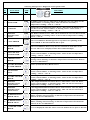
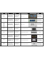
Samsung 'Refrigerator' Diagnostic Code Quick Guide
No
Error Items
LED
TROUBLE
1
I/M-SENSOR
Ice Maker Sensor Error- This can be an Electric wire cut, short-circuit,
contact failure, or missing sensor. This can also be caused by a
temperature reading > 122° or < -58 ° F.
2
R-SENSOR
Refrigerator Compartment Sensor Error- This can be an Electric wire
cut, short-circuit, contact failure, or missing sensor. Cause is also a
temperature reading > 122°or < -58 ° F.
3
DEFROST
SENSOR OF R
ROOM
Ref. Defrost Sensor Error- This can be an Electric wire cut, short-circuit,
contact failure, or missing sensor. Cause is also a temperature reading >
122°or < -58 ° F.
4
R-FAN ERROR
This error indicates the Refrigerator Evap Fan is not spinning at the
correct RPM or the fan feedback line is open.
5
I/M FUNCTION
ERROR
This error indicates the Ice tray has not returned to level after an ice
harvest. The error is displayed after three failed attempts.
6
COOL SELECT
ZONE SENSOR
Cool Select Zone Sensor Error- This can be an Electric wire cut, shortcircuit, contact failure, or missing sensor. Cause is also a temperature
reading > 122°or < -58 ° F.
7
R-DEFROSTING
ERROR
Refrigerator Room defrost heater- wire cut, short-circuit, contact failure,
missing sensor housing, or defective temperature fuse/bi-metal. Defrost
on for over 80 minutes
8
PANTRY-DAMPERHEATER ERROR
9
CR-SENSOR
4-Door
CR Compartment Sensor Error- This can be an Electric wire cut, shortcircuit, contact failure, or missing sensor. Cause is also a temperature
reading > 122°or < -58 ° F.
9
PANTRY-SENSOR
ERROR
CR Compartment Sensor Error- This can be an Electric wire cut, shortcircuit, contact failure, or missing sensor. Cause is also a temperature
reading > 122°or < -58 ° F.
Sensor system in Pantry Room errors
DEFROST
10 SENSOR OF CR
ROOM 4-Door
CR Compartment Defrost Sensor Error- This can be a wire cut, shortcircuit, contact failure, or missing sensor. This can also be caused by a
temperature reading > 122° or < -58 ° F.
DEFROST
11 SENSOR OF CF
ROOM 4-Door
CF Compartment Defrost Sensor Error- This can be a wire cut, shortcircuit, contact failure, or missing sensor. This can also be caused by a
temperature reading > 122° or < -58 ° F.
CR-DEFROSTING
ERROR 4-Door
CR Compartment Defrosting heater- wire cut, short-circuit, contact
failure, missing sensor housing, or defective temperature fuse/bi-metal.
Defrost on for over 80 minutes
CF-DEFROSTING
13
ERROR 4-Door
CF Compartment defrosting heater- wire cut, short-circuit, contact
failure, missing sensor housing, or defective temperature fuse/bi-metal.
Defrost on for over 80 minutes
12
14
WATER HEATER
ERROR
Error is displayed when the water reservoir tank heater is open or shorted
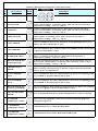
Samsung 'Refrigerator' Diagnostic Code Quick Guide
No
Error Items
LED
TROUBLE
15 EXT-SENSOR
Ambient Temp. Sensor Error- This can be an Electric wire cut, shortcircuit, contact failure, or missing sensor. This can also be caused by a
temperature reading > 122° or < -58 ° F.
16 F-SENSOR
Freezer Compartment Sensor Error- This can be an wire cut, shortcircuit, contact failure, or missing sensor. This can also be caused by a
temperature reading > 122° or < -58 ° F.
17 F-DEF-SENSOR
Freezer Room Defrost Sensor Error- This can be a wire cut, short-circuit,
contact failure, or missing sensor. This can also be caused by a
temperature reading > 122° or < -58 ° F.
18 F-FAN ERROR
This error indicates the Freezer Evap. Fan is not spinning at the correct
RPM or the fan feedback line is open.
19 C-FAN ERROR
This error indicates the Condenser Fan is not spinning at the correct RPM
or the fan feedback line is open.
20 CF-SENSOR 4-Door
CF Room Sensor Error- This can be a wire cut, short-circuit, contact
failure, or missing sensor housing. This can also be caused by a
temperature reading > 122° or < -58 ° F.
FRENCH DOOR ICE
20
ROOM SENSOR
Ice Room Compartment Sensor Error- This can be an Electric wire cut,
short-circuit, contact failure, or missing sensor housing. Cause is also a
temperature reading > 122°or < -58 ° F.
F-DEFROSTING
21
ERROR
Freezer Compartment defrosting heater- wire cut, short-circuit, contact
failure, missing sensor housing, or defective temperature fuse/bi-metal.
Defrost on for over 80 minutes
22
CF-FAN ERROR
4-Door
This error indicates the CF Compartment Evap. Fan is not spinning at the
correct RPM or the fan feedback line is open.
23
CR-FAN ERROR
4-Door
This error indicates the CR Compartment Evap. Fan is not spinning at the
correct RPM or the fan feedback line is open.
23
FRENCH DOOR ICE
ROOM FAN ERROR
This error indicates the Ice Room Compartment Evap. Fan is not spinning
at the correct RPM or the fan feedback line is open.
25
ICE PIPE HEATER
ERROR
Error is displayedwhen the ice maker fill pipe heater is open or shorted.
26
Uart ERROR
COMMUNICATION
This error is not applicable, if the error is detected during diagnostic
testing please ignore it.
27
L↔M ERROR
COMMUNICATION
Communication error within the Main PCB
28
P↔M ERROR
COMMUNICATION
Communication between the Main PCB and Keypad
Samsung 'Refrigerator' Diagnostic Code Quick Guide
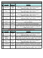
Samsung Single Evaporator 'Refrigerator' Diagnostic Code Quick Guide
No
Error Items
Display LED
1
Fridge Sensor
Fridge
"Mid"
2
Peripheral Temp
Sensor
Fridge
"Min"
3
Freezer Sensor
Freezer
"Max"
4
Freezer Defrost
Sensor
Freezer
"Mid"
5
Freezer Defrost
Error
Freezer
"Min"
6
I/M Function
Error
No Ice
7
I/M Sensor Error
Cubed Ice
TROUBLE
Fridge Room Sensor Error- This can be an wire cut, short-circuit,
contact failure, or missing sensor. This can also be caused by a
temperature reading > 149° or < -58 ° F.
Ambient Temp. Sensor Error- This can be a wire cut, short-circuit,
contact failure, or missing sensor. This can also be caused by a
temperature reading > 149° or < -58 ° F.
Freezer Room Sensor Error- This can be an wire cut, short-circuit,
contact failure, or missing sensor. This can also be caused by a
temperature reading > 149° or < -58 ° F.
Freezer Room Defrost Sensor Error- This can be a wire cut, shortcircuit, contact failure, or missing sensor. This can also be caused by a
temperature reading > 149° or < -58 ° F.
Freezer Room defrosting heater- wire cut, short-circuit, contact failure,
missing sensor housing, or defective temperature fuse/bi-metal. Defrost
on for over 90 minutes
This error indicates the Ice tray has not returned to level after an ice
harvest. The error is displayed after three failed attempts.
Ice Maker Sensor Error- This can be a wire cut, short-circuit, contact
failure, or missing sensor. This can also be caused by a temperature
reading > 149° or < -58 ° F.
Samsung Older "RB" Series 'Refrigerator' Diagnostic Code Quick Guide
No
Error Items
Display LED
1
R-SENSOR
Fridge
5
2
DEFROST
SENSOR, R
ROOM
Fridge
d
3
Peripheral Temp
Sensor
Freezer
E5
4
F-SENSOR
Freezer
F5
5
F-DEF-SENSOR
Freezer
d5
TROUBLE
Fridge Compartment Sensor Error- This can be a wire cut, shortcircuit, contact failure, or missing sensor. This can also be caused by a
temperature reading > 150° or < -58 ° F.
Fridge Compartment defrosting heater- wire cut, short-circuit, contact
failure, missing sensor housing, or defective temperature fuse/bi-metal.
This can also be caused by a temperature reading > 150° or < -58 ° F.
Ambient Temp. Sensor Error- This can be an wire cut, short-circuit,
contact failure, or missing sensor. This can also be caused by a
temperature reading > 150° or < -58 ° F.
Freezer Compartment Sensor Error- This can be a wire cut, shortcircuit, contact failure, or missing sensor. This can also be caused by a
Freezer Compartment defrosting heater- wire cut, short-circuit, contact
failure, missing sensor housing, or defective temperature fuse/bi-metal.
This can also be caused by a temperature reading > 150° or < -58 ° F.
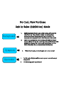
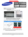
222/Ê(:85&+$6(
1,7,1$/(6Æ;+,%,7,21Ç2'(
ÏÌ
;+,%,7,212'(:+,&+,6$/62&$//('22/,1*2)),621/<)25
6$/(6)/22586(Ì+(6(',63/$<02'(/6$5(%(,1*62/'72
&86720(56:,7+287%(,1*5(029(')5207+,602'(Ì+(
&21680(5:,//&203/$,12)$222/%(&$86(2)7+,602'(
ÐÌ
+(5(,612,1)250$7,21$%28722/,1*2))02'(,1:1(56
0$18$/Æ,1&(,7,6127)2586(56Ç%87620(02'(/6+$9($/$%(/
$77$&+('21',63/$<Ì2,)&22/,1*2)),63(5)250('$1'7+(
/$%(/,6'(7$&+('Ê221(.12:6$%2877+,6)81&7,21Ì
i
z
ÏÌ
+(1'225,623(1Ê,17(51$/,*+76$5(21%8712&22/
ÏÌ
17+,602'(Ê,63/$<$1')$10272523(5$7(1250$//<(;&(37
&2035(6625
ÐÌ
2()5267,1*&<&/(,63(5)250('
v
2'(/
3(5$7,21:$<
62:(52))
,63/$<
(0$5.
ÐÔÓÈÈ
ÐÔÔÈÈ
Press Power Freeze &
Freezer temp buttons
simultaneously for 3 sec
Even though power off
and on again, it remains
exhibition mode
,63/$<“ ”
+(135(66,1*$1<
%87721Ê7:,//',63/$<
6(77,1*7(03)25Ó6(&
ÐÔÕÈÈ
Press Energy Saving &
Freezer temp buttons
simultaneously for 3 sec
Even though power off
and on again, it remains
exhibition mode
,63/$<“ ”
+(135(66,1*$1<
%87721Ê7:,//',63/$<
6(77,1*7(03)25Ó6(&
ÐÔÑÈÈ
ÐÔÓÈÈ
ÐÔÕÈÈ
ÐÔÓÈÈ
ÐÔÕÈÈ
ÐÔ×ÈÈ
Press Power Freeze &
Freezer temp buttons
simultaneously for 3 sec
Even though power off
and on again, it remains
exhibition mode
,63/$<“ ”
Press Power Freeze &
Freezer temp buttons
simultaneously for 5 sec
1&$6(2)2:(52))Ê,7
:,//%(',60,66('
2+$1*(Æ,63/$<6(77,1*7(03Ç
Ï×ÈÈ
ÐÏÈÈ
ÐÔÑÎÈÈ
ÐÓÑÎÈÈ
ÐÓÈÈ
ÐÓÒÒÈÈ
ÐÓÒÓÈÈ
+(135(66,1*$1<
%87721Ê7:,//',63/$<
6(77,1*7(03)25Ó6(&
+(135(66,1*$1<
%87721Ê7:,//',63/$<
6(77,1*7(03)25Ó6(&
Press Ice mode & Freezer
Keys simultaneously for 8
sec
1&$6(2)2:(52))Ê,7
:,//%(',60,66('
Press Power Freeze &
Freezer temp buttons
simultaneously for 3 sec
Even though power off
and on again, it remains
exhibition mode
Press Artic Select Zone &
Freezer Keys
simultaneously for 8 sec
1&$6(2)2:(52))Ê,7
:,//%(',60,66('
2+$1*(Æ,63/$<6(77,1*7(03Ç
+(135(66,1*$1<
%87721Ê7:,//',63/$<
6(77,1*7(03)25Ó6(&
Press Power Freeze &
Freezer temp buttons
simultaneously for 8 sec
1&$6(2)2:(52))Ê,7
:,//%(',60,66('
2+$1*(Æ,63/$<6(77,1*7(03Ç
+(135(66,1*$1<
%87721Ê7:,//',63/$<
6(77,1*7(03)25Ó6(&
2+$1*(Æ,63/$<6(77,1*7(03Ç
22/,1*851('21
7<3(
7<3(
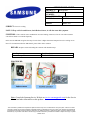
Sensors Control Everything
Do Not Change A Sensor Without Testing It First
Test By DC Voltage only, at the Main PCB, with power on.
Remove sensor from unit to Resistance test
Use the Temperature Resistance, DC Voltage Chart on the following page to test
Functions
Defrost – The sensor shuts off heater At 50 in Freezer, 63 in Fridge
Compartment Temp – The sensor controls fan/compressor on/off to maintain temp
Ice Production – harvests when the I/M sensor reads 1.5 degrees for 5 minutes, Flex Tray Only.
If the door is opened during that 5 minutes harvest is delayed.
Cool Zone Drawer -- Temp control by a sensor that opens or closes an air damper to allow cool air into the
drawer, a heater is built in to the damper to prevent frost.
Ambient Sensor
Fan Speeds – Below 60 degrees condenser fan is off
Defrost Timing – The warmer the room the more often the defrost
**************************************************************************
Failures
Any Sensor Failure will cause the display to come up with a fault code after a power interruption.
Some units will not start up when this happens, others lock the display. To start, put in diagnostics mode.
Defrost
If the sensor is bad it will shut off the defrost circuit in a few minutes or not start, causing ice build-up. This
sensor may also cause the unit to shut down totally at defrost, it will restart after removing power and
restarting unit
Testing: Check the DC voltage across both evap defrost sensors at the Main PCB, with the compressor
running. They should read less than a tenth of a volt difference, as they are both on the same refrigerant line.
They usually read around 3.7 VDC to 3.8 VDC, after the compressor has been running for about 10 minutes,
with the doors closed.
Compartment Temp
After checking for fault codes, unplug unit and plug in after a few seconds. The display will now show
actual compartment temps. Check the actual temps in the top of the compartment and compare to the display
reading. If you are within 2 or 3 degrees the sensors are good.
Ice Production
Off value sensor will cause I/M to harvest before water is frozen or delay harvest for an extended time
Cool Zone Drawer No/poor temp control
Ambient Sensor
This will fail in the “safe mode” causing the main PCB to think the room is hot. Short time between defrosts,
fans at high speed, and slower ice production.
How to Check Sensor Resistances Accurately
Make ice slurry. To do this, fill a cup with ice (preferably crushed), then add water and a teaspoon of salt
to make a slush. Mix thoroughly and allow to sit for 2 to 3 minutes. This will give you a 32*F
reference. Now, lower the sensor into the mixture and leave for about 1 minute, then check the
resistance. It should be very close to 13,300 ohms. Before reinstalling the sensor, be sure to rinse it with
fresh water and dry it.
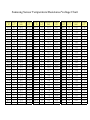
Samsung Sensor Temperature/Resistance/Voltage Chart
Temp. Temp. Resistance Voltage
(℉) (℃)
(㏀)
(V)
-43.6 -42
98.9
4.54
-41.8 -41
93.7
4.52
-40.0 -40
88.9
4.49
-38.2 -39
84.2
4.47
79.8
4.44
-36.4 -38
-34.6 -37
75.7
4.42
-32.8 -36
71.8
4.39
-31.0 -35
68.2
4.36
-29.2 -34
64.7
4.33
-27.4 -33
61.5
4.30
-25.6 -32
58.4
4.27
-23.8 -31
55.6
4.24
-22.0 -30
52.8
4.20
-20.2 -29
50.2
4.17
-18.4 -28
47.8
4.13
16.6 -27
45.5
4.10
-14.8 -26
43.3
4.06
-13.0 -25
41.2
4.02
-11.2 -24
39.2
3.99
-9.4 -23
37.4
3.95
-7.6 -22
35.7
3.91
-5.8 -21
34.0
3.86
-4.0 -20
32.4
3.82
-2.2 -19
30.9
3.78
-0.4 -18
29.5
3.73
1.4
-17
28.1
3.69
3.2
-16
26.9
3.64
5.0
-15
25.7
3.60
6.8
-14
24.5
3.55
8.6
-13
23.4
3.50
10.4 -12
22.4
3.46
Temp. Temp. Resistance Voltage
(℉) (℃)
(㏀)
(V)
12.2 -11
21.4
3.41
14.0 -10
20.5
3.36
15.8
-9
19.6
3.31
17.6
-8
18.7
3.26
19.4
-7
17.9
3.21
21.2
-6
17.2
3.16
23.0
-5
16.4
3.11
24.8
-4
15.7
3.06
26.6
-3
15.1
3.01
28.4
-2
14.5
2.96
30.2
-1
13.9
2.90
32.0
0
13.3
2.85
33.8
1
12.7
2.80
35.6
2
12.2
2.75
37.4
3
11.7
2.70
39.2
4
11.3
2.65
41.0
5
10.8
2.60
42.8
6
10.4
2.55
44.6
7
10.0
2.50
46.4
8
9.6
2.45
48.2
9
9.2
2.40
50.0
10
8.8
2.35
51.8
11
8.5
2.30
53.6
12
8.2
2.25
55.4
13
7.9
2.20
57.2
14
7.6
2.15
59.0
15
7.3
2.10
60.8
16
7.0
2.06
62.6
17
6.7
2.01
64.4
18
6.5
1.97
66.2
19
6.2
1.92
Temp. Temp. Resistance Voltage
(℉) (℃)
(㏀)
(V)
68.0
20
6.01
1.88
69.8
21
5.79
1.83
71.6
22
5.58
1.79
73.4
23
5.38
1.75
75.2
24
5.19
1.71
77.0
25
5.00
1.67
78.8
26
4.82
1.63
80.6
27
4.65
1.59
82.4
28
4.49
1.55
84.2
29
4.33
1.51
86.0
30
4.18
1.47
87.8
31
4.03
1.44
89.6
32
3.89
1.40
91.4
33
3.76
1.37
93.2
34
3.63
1.33
95.0
35
3.51
1.30
96.8
36
3.39
1.27
98.6
37
3.28
1.23
100.4 38
3.17
1.20
102.2 39
3.06
1.17
104.0 40
2.96
1.14
105.8 41
2.86
1.11
107.6 42
2.77
1.09
109.4 43
2.68
1.06
111.2 44
2.59
1.03
113.0 45
2.51
1.00
114.8 46
2.43
0.98
116.6 47
2.35
0.95
118.4 48
2.28
0.93
120.2 49
2.21
0.90
DEFROST ISSUES – FRIDGE & FREEZER
NOTE: Evaporator Covers May Break If Removed While Frozen To Coil. They must be replaced if there is
any damage, this will cause “ice” to form at top or bottom of the evap coil or in the drains.
Frozen Evaporator
Ask Consumer if there has been water on the bottom of the Fridge compartment or ice on the bottom of the
Freezer compartment
Yes – Check for frozen drain and/or open drain heater
Ice/Frost on Evaporator
While checking Main PCB always check both Freezer & Fridge components
Testing: Use Safety Pin to prevent connector damage per following picture
Check the DC voltage across both evaporator defrost sensors at the Main PCB, with the compressor running. They
should read less than a tenth of a volt difference, as they are both on the same refrigerant line. They usually read
around 3.7 VDC to 3.8 VDC, after the compressor has been running for about 10 minutes, with the doors closed.
You may find one reading about 20 to 50 degrees off (lower VDC - higher temp), if so, replace it.
Note: A defective sensor may check OK at room temperature, test at operating temperature only.
Defrost AC voltage tests
Note: The Defrost Sensors are in the circuit during forced defrost, if compartment is over sensor cutout temp Forced
Defrost will cut off within about 2 minutes.
Plug in CN70. Plug in unit. Force Defrost per instructions
Check heater circuit voltage at the Main PCB; look for 120 VAC for Freezer and Fridge
Freezer, See circuit diagrams usually Orange to Brown on CN70
Fridge, See circuit diagrams usually Orange to White on CN70,
No AC Voltage? Change Main PCB
Defrost Resistance tests
Freezer – Unplug unit. Remove defrost connector from PCB
Check heater circuit resistance at the Main PCB connector; look for 35-50 Ohms average
See circuit diagrams usually Orange to Brown on CN70,
Fridge – Unplug unit. Remove defrost connector from PCB
Check heater circuit resistance at the Main PCB connector; look for 60-95 Ohms average
See circuit diagrams usually Orange to White on CN70,
If resistance is around 2600 ohms, Thermo-Fuse/Bimetal is good, Defrost heater is open.
Open Circuit? Check Thermal Fuse, Heater and Connectors
Fast Defrost Check Force defrost on both, Amp probe on Freezer wire about 2.2 amps, see circuit diagrams usually
Brown on CN70.
Amp probe on Fridge wire about 1.2 amp, see circuit diagrams usually White on CN70.
No/Low amp reading, do resistance/voltage tests above.
RM255*** & RM257*** Heater Resistance Readings
Readings at CN70
Black to CN72 Orange - Fresh Zone Defrost Heater 160 ohms
Yellow to CN72 Orange - Arctic Zone Defrost Heater 131 ohms
White to CN72 Orange - Refrigerator Defrost/Drain Heater 152 ohms
Brown to CN72 Orange - Freezer Defrost/Drain Heater 64 ohms
Reading at CN76
White to Sky Blue - Water Tank Heater 49 ohms
Orange to Black - Fill Tube Heater 29 ohms
Reading at Arctic Zone back wall connector
Freezer Defrost Drain Heater 2600 ohms
Reading at Fresh Zone back wall connector
Refrigerator Defrost Drain Heater 2600 ohms
RF26*** Heater Resistance Readings
Readings at CN70
Yellow to CN71 Orange - French Heater (on Left Fridge Door) 1356 ohms
White to CN71 Orange - Refrigerator Defrost Heater 110 ohms
Brown to CN71 Orange - Freezer Defrost Heater 55 ohms
Reading at Ice Pipe Heater in Freezer Compartment
Ice Maker Fill Tube heater1336 Ohms
Frost and Ice Buildup
•
Ice build up in either the freezer or refrigerator compartment can be caused by a blocked drain. It is
possible that the drain is not being defrosted by the heaters enough to properly clear the drain and pass
the melted water into the catch pan.
•
Other Symptoms- Noise from the refrigerator or freezer fan or weak cooling.
Noise disappears when the customer opens door.
The defrost sensor, heater, thermal fuse/bimetal device are OK but ice is built up in the drain hole of
evaporator cover.
Explanation
•
The heat from the defrost heater does not transfer heat to the drain hole through the evaporator cover.
•
The Styrofoam around the fan absorbs moisture and frost begins to form on the evaporator.
•
During the defrost cycle, the frost melts and drips down to the drain where it becomes frozen again.
•
Ice blockage in the drain grows larger with every defrost cycle.
•
Because of the growing ice block, cooling efficiency diminishes at a growing rate and eventually blocks
the fan blades.
•
Self diagnostics will eventually show a fan error.
Solution
•
Metal clips “A” and “C” can be placed on both the evaporator cover and the evaporator. The metal clips
will touch and transfer heat more efficiently from the defrost heaters to the drain preventing ice build up.
•
Part numbers for these parts are as follows:
•
A: DA61-03502A PLATE-DRAIN INS EVAP, REF
•
C: DA61-03585A
FIXER-EVAP REF
Ice Production and Water issues
No Ice Production – Flex Tray
For the ice maker to operate properly, water pressure between 20 and 125 psi is required. A quick test of water
pressure would be filling a 6 oz paper cup in less than 10 seconds. If the internal water filter is clogged, the
water pressure to the icemaker will be reduced. The foreign matter at the water supply valve near the icemaker
can also reduce the water pressure. Additionally, low water pressure at the fill tube can be caused by a defective
fill tube heater.
If the tray seems to be filling completely but the unit never harvests, verify the operation of the Icemaker sensor
in the tray. Normally the unit harvests when the sensor reads approximately 1.5 degrees Fahrenheit for 5
minutes. The sensor should read 3.7 volts at the main board connector when the cube temperature is 1.5 degrees.
After the fill the sensor will read water temp, 1.5 to 2.2 volts. Remember, using frame ground might produce
inaccurate values; instead use the DC ground on the PC board. If this value is incorrect the sensor is suspected
to be defective.
You can also verify the operation of the harvest motor by pressing the black test unit on the motor housing near
the back of the assembly.
Slow Ice production – Flex Tray
This problem is usually caused by a defective sensor or low water pressure. Use the procedure described above
to test the sensor operation. The I/M sensor will delay the time by adding extra fills if the water pressure is low.
Also check the operation of the freezer, if the freezer temperature is above 1.5 degrees, ice production will be
delayed. This can also be caused by a problem with the freezer air vent, make sure the air duct near the ice
maker is not restricted. Look for frost in the ice maker and ice bucket area, if any is found there could be an air
leak through the ice chute flapper. If the unit is on an R/O water system, water pressure may be to low for
consistent ice production. Finally make sure the most updated version of Ice maker kit has been installed. The
ice maker designs in many models have been updated for better performance. Check GSPN for any related
service bulletins regarding Ice-maker changes.
Shattered Ice – Flex Tray
When all ice shatters it's because of a bad tray or harvesting at a temp that is too cold (lower than -5 degrees), in
some areas there are water issues that can also cause shattered cubes. The temp in the freezer should not have
any effect on this issue, as long as it’s below 1.5 degrees, as a properly installed sensor will not read the freezer
temp, only the water/ice temp.
Check the Ice tray for defects in the plastic. Impurities or hard water can cause the plastic to become rough and
inhibit the ice falling from the tray during the twisting. If this is the case, replace the tray assembly.
Strangely enough, it is possible to get ice too cold. Ice that is too cold will shatter during harvest. This can be
from the (1) sensor not reading the correct temp (2) the sensor not mounted correctly (3) by programming the
icemaker offset value to a lower number (4) the board not understanding the reading.
To check the sensor you must check the tray temp (not air temp) and compare it to the sensor reading. The
sensor should read 3.7 volts at the main board connector when the cube temperature is 5 degrees. After the fill
the sensor will read water temp 1.5 to 2.2 volts.
To clear offsets, put unit into Diagnostics mode.
Please note, some shattering is normal for a flex tray icemaker.
Ice Production and Water issues
Overfilling the Ice tray
This can be caused by installing the refrigerator on a non-level floor. Usually the door will not auto-close
properly as well. Another issue that causes this is the fill valve not shutting off. This can be foreign matter in the
valve or insufficient water pressure.
Check the Ice tray for defects in the plastic. Impurities or hard water can cause the plastic to become rough and
inhibit the ice falling from the tray during the twisting, leaving some cubes, causing an over fill. If this is the
case, replace the tray assembly.
This can also be caused by a crack in the icemaker support (on some models) which will prevent the cube
harvest and may allow more water to be dumped over the existing cubes.
Bulletin # ASC20041012002.Ice Harvest Failure RS2533SW/XAA,RS2544SL/XAA,
RS2555SL/XAA,RS2555SW/XAA, RS2577SL/XAA,RS2577SW/XAA
Overfilling the Ice Bucket
If the bucket overfills, do a test harvest and put your hand under the full bucket sensor arm to simulate a full
bucket. If it still completes the harvest, replace the ice-maker ass’y.
Ice-Maker not harvesting or stalling during harvest (test and operation)
At the main PCB connector CN90 check motor voltage at pins 1 & 2 (red & black wires) it should be about
10vdc when you activate the test by shorting pins 5 & 8 (gray & sky blue wires). You will read a +10vdc at the
start of the flex, when the tray reaches max flex, the voltage switches to -10vdc.
If you don’t have the 10vdc replace the Main PCB, if voltage is proper replace ice-maker ass’y.
Ice Production and Water issues
Ice Bucket – Crushed/Cube issues
Check the ice bucket is it properly inserted; check the solenoid lever of ice bucket, is it operating freely, if not
check for ice/frost build-up in the auger motor area.
Please Note, on most older models:
When the unit is making ice, and the ice bucket is not full, the freezer will be in continuous Power Freeze. This
can create very cold temps in the freezer compartment, down to -12. Also if there is no water hooked up to the
ice maker it will try to make ice and never fill the bucket. This is normal operation. Some models after 2007
will not do this
To turn off the icemaker on Samsung Refrigerators use the “Ice Off” button on the front display panel. Always
turn off the ice function if water is not hooked up to the unit.
No water from Dispenser
NOTE: Filter or bypass must be in place
Disconnect water line from door, push water dispenser.
If you have water, check for a frozen line in the door, replace door
No water, check for frozen water tank
If frozen, check water tank heater (Evaporator Cover) and/or check for defrost problem, ice build up could
freeze the tank.
If the tank is OK, check the output of the water valve
Water Valve: If low or no output, check input before replacing. Remove the water filter then remove the input
line to the water valve, put the line in a bucket and install filter then check water flow, if good replace valve.
If you still have poor water flow, check house supply, if that’s good then replace filter
Water leaks on the floor
You first have to determine if it’s from the defrost system or water dispensing plumbing.
To check defrost system, you must put water into the defrost heater drain in each compartment and check for
any leaks after each test.
To check the cube water fill system, do a test harvest of the ice-maker two or three times and look for any leaks.
Fill two or three glasses from the door dispenser and check for any leaks.
Water dispenser leaks at fountain
Check output of dispenser water valve for any leakage, if leaking, check for low water pressure or a bad valve.
If it is not leaking, the water line fitting at the door hinge may be letting air in, check this fitting. The water in
the dispenser tank may have air in it, it will slowly bubble out and force water out the dispenser in the door,
creating drips and consumer complaints.
Every time the consumer uses the dispenser there is more air/water put into the tank and it keeps dripping. This
is from well water, or city water systems that force air into the water. See Bulletin on following page.
Samsung French Door Refrigerator
Ice Making Characteristics
IMPORTANT ! Procedure required to initialize a new French Door Refrigerator
or whenever the ice bucket is emptied.
French Door Refrigerator (FDR) designs require a compact designed ice maker; therefore, initial
setup of the ice maker is critical to sufficient ice production. Samsung FDR uses a solid blade auger
to allow smooth transport of ice cubes. Ice buildup will occur if the ice is not dispensed during the
initial setup, or when the ice bucket is fully emptied. Instruct the customer to follow the procedure
below for proper initialization. Remember; always discard the first bucket of ice.
Key Point;
The FDR ice making process drops the cubes into the same area,
making a pile under the ice maker. The Ice Level sensor "sees" the
pile of ice and stops production. During the first 24-36 hours, or
after emptying the ice bucket, if you do not follow the procedure
below, the ice maker remains off.
Dispensing the ice will cause the auger to evenly distribute the ice
cubes. This is key to achieving normal ice production on a
French Door Refrigerator.
Procedure to Initialize the Ice Maker
To maximize ice cube production, follow these steps:
Make sure the water line is connected and the water valve is fully open.
1.
2.
3.
Allow the refrigerator to cool for 24 hours before dispensing ice for the first time.
Ice is accumulated under the ice maker as in Figure 1 on the next page. If not, allow 6 hours
more then dispense a few cubes of ice. This causes the auger in the ice bucket to distribute
the cubes evenly in the ice bucket as in Figure 2. The ice maker then detects a “low ice
condition” and resumes making ice.
After an additional 6 hours, cubes will accumulate in the rear of the icemaker as in Figure 3.
Dispense a few more cubes of ice again. This causes the auger in the ice bucket to distribute
the cubes evenly in the ice bucket as in Figure 4 below. From this point on, ice cubes will be
evenly dispersed within the ice bucket. Ice production will start whenever the icemaker
senses a “low ice condition”.
Figure 1: Ice accumulates
under the ice maker
In the initial ice making process, the
cubes accumulate at the rear of the
ice bucket, under the ice maker as
shown above.
Figure 3
After an additional 6 hours, cubes once
again accumulate at the rear of the ice
bucket.
Note 1:
Figure 2: After dispensing a few
cubes of ice, the auger will disburse
the ice evenly
After the initial ice making process,
dispensing a few cubes will allow the
auger to disburse the cubes evenly.
Figure 4
Dispense a full glass of cubes. This will
allow the auger to disburse the cubes
evenly.
For additional ice, empty the full ice bucket into another container. The ice maker will sense
a low ice condition and produce more ice.
Note 2: For your refrigerator to dispense ice, you must have:
•
•
The refrigerator doors closed.
The ice maker selector on Cubed or Crushed.
Slow Ice Production
Heat Release I/M (Models RF267**, RF26V**, RFG***)
Normal Ice Production, after first day, is 50 to 90 cubes in 24 hours
Ice production
38 minutes after the water fill is complete, the control board will check the temperature of the eject
Thermistor, if the Thermistor reads a temperature lower than 18.5 degrees for more than 5 seconds,
then the ice production process is completed. The Ice maker will harvest if the ice bucket is not full.
Test Mode
Press and hold the ICE TEST S/W for at least 1.5sec, the harvest function will start. If the ice maker
Thermistor is below 0 degrees the Ice maker heater turns on for an about 2 minutes. If the
temperature exceeds 0 degrees, Ice maker heater turns on for 30 seconds. After the Ice maker
heater turns on for 30 seconds, the heater turns off and then Ice maker harvest motor turns on.
Troubleshooting Observations
Is there any frost in the freezer compartment?
Excessive frost on the evaporator coil will either coat the coil enough to warm the air to
32 degrees to supply the ice room or block the air duct completely to the ice room.
Make sure the Freezer defrost heater is working properly and the freezer and ice room
compartments are sealed properly
The consumer complaint could be “it only makes ice once or twice a day” The Ice maker
will harvest within a few hours of the freezer defrost cycle, when the evaporator is frost
free. As the frost builds up on the evaporator again the ice maker will stop as the
temperature is too warm. Ice making will stop until the next defrost cycle completes
which will be 12 to 23 hours later. This is a defrost error not an icemaker error. Check
the freezer door seal, ice room door seal and the freezer defrost heater.
Is the Ice Bucket locked firmly in position?
Try to move the bucket, when locked in place, any movement would mean that one of
the locks is not latched. This will cause warm fridge air to enter the ice room and stop
ice production.
Temperature checks (Actual) These values are approximate
The Back of Ice Room should measure 0 to 6 degrees when making ice
The Back of Freezer compartment should measure -4 to +3 degrees
Voltage tests
The Ice Room Sensor voltage should match the actual ice room temperature; refer to the
sensor voltage/ temperature chart in the service manual.
The Freezer Sensor voltage should match freezer temp and also be close to the actual ice
room temperature, refer to the sensor voltage/ temperature chart in the service manual. If the
bucket is full the Ice Room temperature should be around 24 degrees.
The Freezer Defrost Sensor Voltage should be 0 to -17 degrees (3.7 – 4.1v), with the
compressor running, to show no frost/ice buildup and good operating system, refer to the
sensor voltage/temperature chart.
The Ejecting Thermistor should not measure below 17 degrees, unless the bucket is full, as it
should harvest at 18 degrees. If Ejecting Thermistor measures actual ice room temperature,
and the bucket is not full, it would mean that the I/M is not harvesting. If there has been a
recent harvest, the thermistor might measure up to 50 degrees (2.35V) as the mold heater and
fresh water has warmed the sensor.
If any of the sensors measure incorrectly replace the defective sensor
The Ice Room Fan should read around 7 to 9 VDC when it is running. Be sure to defeat the
door open switch when testing the fans. You can force the fan to turn on by putting unit in
Forced Freeze mode.
If the I/M Thermistor reads below 18 degrees (3.2V) after 38 minutes and there is no harvest
replace the main PCB
Test Points
Ice Room Sensor - on RF267 & RF26V - CN32 Pin 3 (Orange) to CN75 Pin 1(Gray)
Ice Room Sensor - on RFG – CN31 Pin 3 (Orange) to CN76 Pin 1 (Gray)
Freezer Defrost Sensor - on RF267 & RF26V - CN30 Pin 4 (Orange) to CN75 Pin 1 (Gray)
Freezer Defrost Sensor - on RFG - CN30 Pin 4 (Orange) to CN76 Pin 1 (Gray)
Freezer Room Sensor - on RF267 & RF26V - CN30 Pin 3 (Red) to CN75 Pin 1 (Gray)
Freezer Room Sensor - on RFG - CN30 Pin 3 (Red) to CN76 Pin 1 (Gray)
Ice Maker Eject Sensor - on ALL Models - CN90 Pin 4 (White) to Pin 8 (Sky Blue)
Ice Room Fan – on RF267 & RF26V - CN76 Pin 1 (Black) to CN75 Pin 1 (Gray)
Ice Room Fan – on RFG - CN76 Pin 2 (Black) to Pin 1 (Gray)
DC FAN MOTORS
Brushless DC Fan motors are used to save energy. The fans
operate at two speeds, High when the ambient temperature is high
and Low when the temperature is low. Generally, it is operated in
the High mode during a day time and in the Low mode at night.
This circuit design is to protect the Main PCB from a failed fan
motor
Fan speed information is read by the Main PCB. If the fan speed
exceeds 600 RPM or the speed is too slow, or stopped the fan drive
circuit is disabled,
After 10 seconds the circuit tries again with 3 seconds of DC
voltage
If the fan continues this activity for 5 cycles, 10 seconds off 3
seconds on, the fan drive circuit is disabled for 10 minutes.
TO TEST THE FAN CIRCUIT VOLTAGE.
Power off for 15 seconds, power on to check the DC
voltage to the motor, wait from 10 to 60 seconds for the fan
voltage to kick in, and then check fan voltage, the average
reading is 9 VDC. If you get 3 seconds of voltage every 10
seconds for the 5 fan power up cycles, then the Main PCB
is good.
NOTE: You may need to put unit in FORCED FREEZE
mode to activate the fans/compressor.
If the fan blade is blocked by ice, then defrost and check
the motor again, after removing power from the unit.
If the evap is ice blocked and thus blocking the air flow, the
fan will over RPM and is stopped. Remove ice and check
the motor again.
If everything is clear around the fan blade then the motor
would be at fault.
Continuous fan errors will be displayed on the front panel display.
PLEASE NOTE: The door switches control the evap fan motors.
Have them closed to test the motors
An intermittent evap fan door switch could cause an intermittent
no cool condition.
Thermo-Fuse Failures
Thermal-Fuse replaced with Bimetal element in Both sections RB******* & RS*******
CRITICAL: Always Replace Defrost Sensor When Thermo-Fuse Fails
DA47-10160H
Water Dripping from Water Dispenser on French Door Models Ice/Frost Build Up on Evaporator Cover, Evaporator Coil Clear
RS2621SW,RS2622SW,RS2623BB,RS2623SH,RS2623SL,RS2623VQ, RS2623WW,
RS2624SW,RS2624WW,RS2625SL,RS2630SH,RS2630SW,RS2630WW, RS2631SL,
RS2640SW,RS2644SL, RS2644SW, RS265LABB, RS265LABP, RS265LASH, RS265LAWW, RS2666SL,
RS2666SW,RS267LABB,RS267LABP/SH, RS267LABP,RS267LASH,RS267LAWW,RS269LARS
Repair Kit for Serial Number range: up to **43CL3*****, up to **42BL3***** Units manufactured
before April of 2006
For all above models
Inspect for air leaks: Door Seal, Ice Chute, I/M Fill Tube,
Liner cracks around/behind evap coil
Air leak around defrost drain hose at evap coil.
Excessive door openings, or doors left open for long periods.
Please use only in the listed Models
Other Models use a different Main PCB
SERVICE BULLETIN
PRODUCT:
Refrigerator
BULLETIN NUMBER: ASC20071012001
BULLETIN DATE: 12-OCT-2007
RF267AABP, RF267AARS,
MODELS:
RF267AASH, RF267AAWP
Chassis
AW-PJT
SUBJECT: No Ice Production / Ice Not Available
SYMPTOM: 1) No or Low Ice Production.
2) Ice Jamming.
3) Clicking or Grinding noise from Ice Maker ASSY.
CAUSE: When the ice tray dumps ice cubes to the ice bucket, ice cubes
jam between the ice tray and the liner. The ice maker
makes a loud noise and eventually stops working.
REPAIR: Replace Ice Maker Service Kit (Ice Maker and Main PCB).
Part Number: DA81-01421A
Description: Ice Maker Service Kit
NOTE: If the service kit is not available. Please order DA97-05422A (Ice Maker ASSY)
and DA41-00413C (Main PCB ASSY) separately.
This information is published for experienced repair technicians only and is not intended for use by the public. It does not contain
warnings to advise non-technical individuals of possible dangers in attempting to service a product. Only experienced professional
technicians should repair products powered by electricity. Any attempt to service or repair the product or products dealt with in this
information by anyone else could result in serious injury or death. Information provided in this bulletin is subject to change or update
without notice.
SERVICE BULLETIN
Refrigerator
PRODUCT:
BULLETIN
NUMBER:
BULLETIN DATE:
RM25**
MODELS:
Chassis
NEXT PJT
SUBJECT: Excessive cooling
NOTE: If Evap coil is frosted/frozen, check Defrost Sensor, it will also cause this symptom.
SYMPTOM: There could be water condensation on sensor housing (connector) of arctic zone when customer
switch freeze mode to cool mode frequently.
In this case the MICOM recognizes the temp of Arctic Zone is higher than actual temp and excessive cooling occurs.
Note: If it is manufactured before March 2007, please follow below solution
REPAIR: Replace sensor and sealing the connector with insulation tape
Part Used
Part Number
Sensor Temp - R
DA32-00011C
PROCEDURE:
Note: Consult the Samsung Service Website at (service.samsungportal.com) for the Service
Manual and other information on this product.
This information is published for experienced repair technicians only and is not intended for use by the public. It does not contain
warnings to advise non-technical individuals of possible dangers in attempting to service a product. Only experienced professional
technicians should repair products powered by electricity. Any attempt to service or repair the product or products dealt with in this
information by anyone else could result in serious injury or death. Information provided in this bulletin is subject to change or update
without notice.
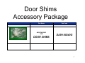
Door Shims
Accessory Package
Part Name
ASSY-PACKING
SUB
DOOR SHIMS
Part Code
DA99-00240G
1
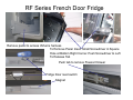
RF Series French Door Fridge
Remove panel to access I/M wire harness
To Remove Panel Insert Small Screwdriver in Square
Hole at Bottom Right Corner. Push Screwdriver to Left
To Release Tab
Push tab to remove Freezer Drawer
Fridge Door reed switch
Magnet
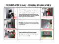
RFG295/297 Cover - Display Disassembly
Screwdriver
Slot Area
Insert a flat-blade screwdriver into slotted area
as shown in photo right. After inserting the
screwdriver into the slotted area, place one hand
underneath the panel, while twisting the screw
driver CCW pull the panel out toward the front
until the right side pops out. Once the right side
pops out the panel is easily removed.
Place screwdriver into slot
DO NOT try and pry the panel out by pushing,
or pulling the screwdriver. This will only damage
the slotted area.
Slotted area is cracked
Do go forward, or backward
Once the display panel has been removed
disengage the housing connections of display
cover. Remove 3 screws of cover display and
remove display panel PCB.
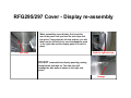
RFG295/297 Cover - Display re-assembly
When assembling cover display, first insert the
rear of the panel until you hear the side clips click
into place. Than press the left side and top, you will
than hear the left side lock, once that happens push
in the right side and the display panel in locked in
place.
Side clips
Push the right side last
DO NOT reassemble the display panel by pushing
straight back and than up. The side clips will
damage the side walls as shown in the right side
photo.
Damage
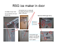
RSG ice maker in door
Ice bucket ass’y is removed by pulling the locks on both Ice Maker Cover: Pull out on bottom of cover sides of the bin.
and lift up
Remove I/M Auger Ass’y
Remove 4 screws
Ice bucket reed switch, Ice Off LED flashes if bucket is not in place
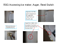
RSG Accessing Ice maker, Auger, Reed Switch
Squeeze in at this point and pull out on auger/ice maker ass’y on the left side
Wiring harnesses are behind ass’y
Auger/ice maker ass’y has plastic that locks into the two pieces on the door liner
Samsung Electronics America, Inc.
Date: 30-May-2007
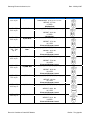
Room Area
Recommended BTU
Model - Dimension - Weight
10' x 15'
150 sq. ft.
5,050 BTU
10' x 20'
200 sq. ft.
6,000 Btu.
10' x 20'
200 sq. ft.
6,000 Btu.
16' - 17' x 20'
300 - 340
sq. ft
7,500 - 8,000
Btu.
18' x 25'
450 sq. ft.
10,500 Btu.
22' x 25'
550 sq. ft.
12,300 Btu.
25' x 30'
750 sq. ft.
14,700 Btu.
25' x 40'
1000 sq. ft.
18,000 Btu.
35' x 40'
1400 sq. ft.
25,000 Btu.
AW05NCM7/XAA
DIMENSIONS: 16.75" x 12.2" x 13.5"
WEIGHT: 37.7 lbs.
9.7 EER
Mechanical
AW06NCM7/XAA
DIMENSIONS: 16.75" x 12.2" x 13.5"
WEIGHT: 39.6 lbs.
9.7 EER
Mechanical
AW06ECB7/XAA
DIMENSIONS: 19.3" x 12.6" x 18.1"
WEIGHT: 47.4 lbs.
10.7 EER
Electronic/Remote Control
AW08ECB7/XAA
DIMENSIONS: 19.6" x 14" x 18.1"
WEIGHT: 56.5 lbs.
10.8 EER
Electronic/Remote Control
AW10ECB7/XAA
DIMENSIONS: 22" x 15.5" x 22"
WEIGHT: 75.6 lbs.
10.8 EER
Electronic/Remote Control
AW12ECB7/XAA
DIMENSIONS: 22" x 15.5" x 22"
WEIGHT: 80.9 lbs.
10.8 EER
Electronic/Remote Control
AW15ECB7/XAA
DIMENSIONS: 24.6" x 16.6" x 25.2"
WEIGHT: 101 lbs.
10.7 EER
Electronic/Remote Control
AW18ECB7/XAA
DIMENSIONS: 24.6" x 16.6" x 25.2"
WEIGHT: 108.2 lbs.
10.7 EER
Electronic/Remote Control
AW25ECB7/XAA
DIMENSIONS: 26" x 17.6" x 28.1"
WEIGHT: 131.4 lbs.
9.4 EER
Electronic/Remote Control
Room Air Conditioner Chart 2007 Models
Electrical Requirements
Drafter: Tony Ippolito