1
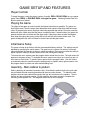
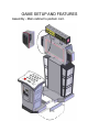
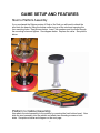
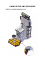
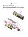
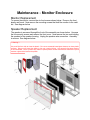
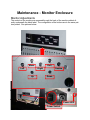
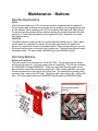
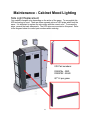
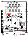
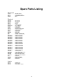
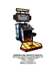
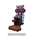
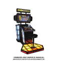
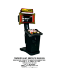
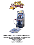
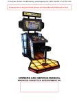
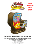
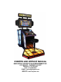
OWNERS AND SERVICE MANUAL INNOVATIVE CONCEPTS IN ENTERTAINMENT INC. 10123 MAIN ST., CLARENCE, NY 14031 SERVICE: 1-716-759-0360 FAX: 1-716-759-0884 E-MAIL: [email protected] WEBSITE: www.icegame.com TABLE OF CONTENTS SAFETY AND WARNINGS x x x 3 Before You Begin Installation Warning GAME SETUP AND FEATURES x x x x x Player Controls Playing The Game Initial Game Setup Assembly - Main cabinet to Podium & Speakers Stool to Platform Assembly ADJUSTMENTS & AUDIT MENU SYSTEM x x x x x x x x x x x x x x 5 6 8 Main Menu Operator Adjustments Game Adjustments Ticket MECH adjustments Coin Settings Player Cost/ Payout Volume General Audits Game Audits Ticket Audits System Audits Coin Audits Reset Menu System Test MAINTENANCE x x x x x x x x x x x x x x 4 15 Access the Computer AC Power fuse Power Supply Replacement and Adjustments Main and I/O board replacement Platform Lights replacement Marquee Bulbs replacement Cleaning Monitor Replacement Speaker Replacement Monitor Adjustments Deal No Deal and Suit case Buttons and bulbs Side Light Replacement System Wiring both 110v and 220v Spare Parts List WARRANTY INFORMATION 16 17 18 19 20 21 22 24 28 29 2 SAFETY AND WARNINGS BEFORE YOU BEGIN WARNING: WHEN INSTALLING THIS GAME, A GROUNDED A.C. RECEPTACLE MUST BE USED. FAILURE TO DO SO COULD RESULT IN INJURY TO YOURSELF OR OTHERS. FAILURE TO USE A GROUNDED RECEPTACLE COULD ALSO CAUSE IMPROPER GAME OPERATION, OR DAMAGE TO THE ELECTRONICS. DO NOT DEFEAT OR REMOVE THE GROUNDING PRONG ON THE POWER CORD FOR THE SAME REASON AS GIVEN ABOVE. USING AN IMPROPERLY GROUNDED GAME COULD VOID YOUR WARRANTY. HAVE A QUALIFIED ELECTRICIAN CHECK YOUR A.C. RECEPTACLE TO BE SURE THE GROUND IS FUNCTIONING PROPERLY. INSTALLATION The game comes ready to play with just a few simple things to keep in mind. 1. Plug the game into the A.C. outlet and turn on power to the game. The switch for the game is located on a power module on the outside rear of the game. THIS GAME IS DESIGNED TO DISSIPATE STATIC ELECTRICITY THROUGH THE GROUNDING PLANE OF THE GAME. IF THE A.C. GROUND DOES NOT WORK, THE GAME COULD DISCHARGE STATIC ELECTRICITY THROUGH THE GAME CIRCUITRY, WHICH COULD CAUSE DAMAGE. 2. Make sure the game is level after installation. It is necessary to make sure the game is level for safety concerns. 3. Check that the A.C. voltage rating on the back of the game matches the A.C. voltage of your location. THE POWER SUPPLY IS NOT VOLTAGE ADJUSTABLE. TO OPERATE THE GAME AT VOLTAGES OTHER THAN THOSE IT WAS DESIGNED FOR. PLEASE CONTACT OUR SERVICE DEPARTMENT FOR VOLTAGE CONVERSION INFORMATION. WARNING DO NOT remove any of the components on the main board (e.g. compact flash and eproms) while the game is powered on. This may cause permanent damage to the parts and the main board. Removing any main board component part while powered on will void the warranty. NOTE: THIS GAME IS INTENDED FOR INDOOR USE ONLY. ON THE BACK PANEL OF THE GAME: WARNING: SHOCK HAZARD - DO NOT OPEN. REFER SERVICING TO SERVICE PERSONNEL. 3 GAME SETUP AND FEATURES Player Controls To begin the game, insert the proper number of credits. DEAL OR NO DEAL is a one player game. Select DEAL or DOUBLE DEAL to begin the game. Selecting Double Deal doubles the amount of tickets! Playing the Game The object of the game is to wind up with the highest value deal as possible. The player selects his/her case. Then the player must determine which cases he/she feels hold the lowest value. By selecting the cases, the player eliminates potential deal values. Round to round the banker will offer a deal value that the player is entitled to take. If a deal is taken, the game dispenses the deal value in tickets and the game ends. If the player does not take the bankers deal value throughout the game, he/she will be left with the value inside his/her case. The game will dispense the value of tickets in his/her case and the game ends. Initial Game Setup The game is setup at the factory with the recommended factory settings. The settings may be adjusted by accessing the menu system. The game’s menu system is a series of on screen menus that allow the operator to setup or adjust the settings. Each menu provides the ability to adjust a specific setting or access another menu with other game settings. To access the menu system press the program button inside the coin door. The main menu will appear on the game screen. To navigate the menu system use volume up to scroll up and volume down to scroll down. To select a menu option use the program button. Use the volume up and down buttons to scroll through the setting levels on specific menu option screens. Use the program button to select and save desired setting level. Assembly - Main cabinet to podium Start by attaching all electrical connections first. Now slide the podium flush to the main cabinet and attach the side mounting brackets with three mounting screws. To attach the side speakers onto the main cabinet first connect the two wire connector to the speaker. Then install the two top and bottom screws. Finally install the three back screws to complete the mounting of the speaker unit. See diagrams below and on the next page. 4 GAME SETUP AND FEATURES Assembly - Main cabinet to podium cont. 5 GAME SETUP AND FEATURES Stool to Platform Assembly If you purchased the Deluxe version of Deal or No Deal you will need to attach the stool onto the base by lifting the bottom collar ring up on the stool and exposing the four mounting holes. See pictures below. Insert four washers and four bolts through the mounting holes and tighten. See diagram below. Replace the collar. See picture below. Platform to Cabinet Assembly Now attach the stool assembly to the podium by removing the front bottom bezel. Now slide the stool assembly into the cabinet and attach two mounting screws on both sides. See pictures below and diagram on the next page. 6 GAME SETUP AND FEATURES Platform to Cabinet Assembly cont. 7 DIAGNOSTIC, ADJUSTMENTS & AUDIT MENU SYSTEM MAIN MENU OPERATOR ADJUSTMENTS - adjust various game play/operation settings GENERAL AUDITS - view game/coin/ticket audit data RESET MENU - reset game/coin/ticket audits SYSTEM TESTS MENU - perform various system tests/diagnostics Main Menu - OPERATOR ADJUSTMENTS GAME ADJUSTMENTS - adjust game play settings TICKET MECH ADJUSTMENT - turn the ticket mechanism on/off COIN ADJUSTMENTS - adjust the currency type and coin switch values PLAYER COST / PAYOUT - adjust the cost of the game and the level of payout VOLUME - adjust the volume for the game Main Menu - Operator Adjustments - GAME ADJUSTMENTS FIXED TICKET MODE - XXX COUNTDOWN TIMER DEFAULT=OFF DEFAULT = 10 - the amount of time that the user has to make an input before the game makes an auto-input. The value ranges from 3 to 20 seconds [min = 3, max = 20] COUPONS OR TICKETS DEFAULT = TICKETS - the prizes given out by the game can be labeled as either TICKETS or COUPONS SHUFFLE GAME - XXX SHUFFLE SPEED - XXX DEFAULT=OFF DEFAULT=100% Main Menu - Operator Adjustments - TICKET MECH ADJUSTMENT TICKET OUTPUT - enables/disables output from the ticket mechanism. [ON / OFF] DEFAULT = ON 8 DIAGNOSTIC, ADJUSTMENTS & AUDIT MENU SYSTEM Main Menu - Operator Adjustments - COIN SETTINGS FREEPLAY -allow the game to be played without credits [ON / OFF] DEFAULT = OFF CURRENCY TYPE - the currency type can be set to a variety of world currency values. the default is the US dollar. DEFAULT = DOLLAR CURRENCY UNIT VALUE -the unit value of a single credit. DEFAULT = $0.25 COIN 1 VALUE - the amount of credits given by one pulse from coin switch #1 DEFAULT = $0.25 COIN 2 VALUE - the amount of credits given by one pulse from coin switch #2 DEFAULT = $0.25 COIN 3 VALUE / DBV PULSE - the amount of credits given by one pulse from coin switch #3 or the dollar bill acceptor. DEFAULT = $1.00 MAXIMUM CREDITS - the maximum number of credits allowed by the machine. if more credits than this are inserted, the internal coin meters will still tick, but the game will ignore the input. DEFAULT = $500.00 CREDIT VALUE (Coins Only) - when coins are selected as the currency type, there is an added option for a credit value. this allows the operator to set an alternate value for each coin. for example, if a token was worth only $0.05, the credit value would be set to 0.05. DEFAULT = $0.25 9 DIAGNOSTIC, ADJUSTMENTS & AUDIT MENU SYSTEM Main Menu - Operator Adjustments - PLAYER COST / PAYOUT PAY MODEL DEFAULT = PAY UP FRONT - the game can be set to PAY UP FRONT, where there is a one-time cost to play the game, or PAY PER ROUND, where an individual price can be set for each round of play, and the player is prompted to enter more money as the game goes on. [PAY UP FRONT / PAY PER ROUND] GAME START COST - cost to start the game [min = FREE, max = $25.00] DEFAULT = $1.00 GAME START COST (DOUBLE DEAL) DEFAULT = $2.00 - cost to start the Double Deal game. (note: the Double Deal mode is the same as the regular game, except that all the payout values are doubled. the cost of the Double Deal game should almost always be twice the cost of the regular game.) [min = FREE, max = $25.00] TICKET VALUE - the value of a single ticket in relation to a unit of currency. the default setting is 0.01, which means that one ticket equals one cent. [min = $0.00, max = $1.00] HIGHEST PAYOUT VALUE - the value of a single ticket in relation to a unit of currency. the default setting is 0.01, which means that one ticket equals one cent. [SETTINGS = 100 / 200 / 500 / 1000] DEFAULT = $0.01 DEFAULT = 200 (THE FOLLOWING ADJUSTMENTS ONLY APPEAR IF SET TO “PAY PER ROUND”) ROUND 2 COST DEFAULT = FREE ROUND 3 COST DEFAULT = FREE ROUND 4 COST DEFAULT = FREE ROUND 2 COST (DOUBLE DEAL) DEFAULT = FREE ROUND 3 COST (DOUBLE DEAL) DEFAULT = FREE ROUND 4 COST (DOUBLE DEAL) DEFAULT = FREE - if PAY PER ROUND is selected as the pay model, the operator has the option to set individual costs for each round of play. if a particular round is set to FREE, the player is allowed to play that round without being prompted to enter more credits. 10 DIAGNOSTIC, ADJUSTMENTS & AUDIT MENU SYSTEM Main Menu - Operator Adjustments - VOLUME GAME VOLUME - in-game volume [min = 0, max = 32] DEFAULT = 24 ATTRACT VOLUME - volume of the attract mode [min = 0, max = 32] DEFAULT = 24 MINIMUM VOLUME - the lowest level that both the game and attract mode volumes can be set to. [min = 0, max = 32] DEFAULT = 4 ATTRACT SOUNDS DEFAULT = OCCASIONALLY - how frequently the sounds will play while in attract mode. [SETTINGS = OFF / OCCASIONALLY / ALWAYS] Main Menu - GENERAL AUDITS GAME AUDITS - audits for total number of plays, game time, etc. TICKET AUDITS - audits for the number of tickets won, average tickets, number of tickets owed, etc. SYSTEM AUDITS - audits for play time, up time, etc. COIN AUDITS - audits for the number of coins in, etc. ALL AUDITS ARE VISIBLE IN THE ATTACHED SCREENSHOTS. ****ONE CHANGE IS CURRENTLY BEING MADE: UNDER “COIN AUDITS”, “BONUS COINS” WILL NOT BE PRESENT IN THE FINAL BUILD.**** 11 DIAGNOSTIC, ADJUSTMENTS & AUDIT MENU SYSTEM Main Menu - General Audits - GAME AUDITS TOTAL PLAYS - total number of games played TOTAL DEAL GAMES -- total number of standard games played TOTAL DOUBLE DEAL GAMES - total number of "Double Deal" games played TOTAL WON HIGHEST - number of times the player has won the highest possible value TOTAL WON LOWEST - number of times the player has won the lowest possible value AVERAGE GAME TIME - the length of the average game, specified in minutes TOTAL GAME TIME - the cumulative time the game has been played TOTAL DEALS - number of times players have chosen the "Deal" TOTAL NO DEALS - number of times players have chosen "No Deal" Main Menu - General Audits - TICKET AUDITS TOTAL TICKETS DISPENSED - the total number of tickets given out by the game AVERAGE TICKETS PER PLAY - the average number of tickets given out each game CURRENT PAYOUT PCT - the current payout percentage of the game. this number changes as people play the game, and the game tries to get this value as close to the target payout as possible. TOTAL TICKETS (500 GAMES) - the total number of tickets dispensed in the past 500 games AVG. TICKETS (500 GAMES) - the average number of tickets given out during the past 500 games PAYOUT PCT. (500 GAMES) - the payout percentage for the past 500 games TICKETS OWED - how many tickets are currently owed to the player. this number will be non-zero if there has been some kind of ticket mechanism error (i.e. out of tickets, ticket jam) 12 DIAGNOSTIC, ADJUSTMENTS & AUDIT MENU SYSTEM Main Menu - General Audits - SYSTEM AUDITS PLAY TIME - total play time logged on the game UP TIME - length of time the game has been powered on WATCHDOGS - the number of times the game has forced itself to reset (power cycle) EXCEPTIONS - the number of times the game has detected a software error of type #1 BAD TRAPS - the number of times the game has detected a software error of type #2 Main Menu - General Audits - COIN AUDITS TOTAL COIN 1 - total number of coins read by coin counter #1 TOTAL COIN 2 - total number of coins read by coin counter #2 TOTAL COIN 3 (DBV) - total number of coins read by coin counter #3 (often used for dollar bill acceptors) LIFETIME COIN COUNT - cumulative coin count for all three coin counters SERVICE CREDITS - total number credits added via the "service credits" button Main Menu - RESET MENU RESET GAME AUDITS - reset the game audits (total plays, current payout, etc.) RESET CREDITS - reset the number of credits currently in the game RESET COIN COINTERS - reset the coin audits RESET ADJUSTMENTS - reset the game adjustments (game cost, highest payout, etc.) RESET TICKETS - reset the ticket audits FACTORY RESET - reset all audits (game, credits, coin, adjustments and tickets) 13 DIAGNOSTIC, ADJUSTMENTS & AUDIT MENU SYSTEM Main Menu - SYSTEM TESTS VERSION LIST - display the individual software versions for the game SWITCH TEST - perform a switch test for coin counters, start, volume, test and service buttons SCREEN TESTS - perform a series of screen tests such as color and grid adjustment SOUND TEST - play a series of test sounds to diagnose audio problems FILE TEST - perform a test to validate all of the files used by the game COIN METER TEST - tick the coin meter once TICKET DISPENSER TEST - dispense one ticket from the ticket mechanism DIPSWITCH SETTINGS - read the state of the eight dip switches on the IO board START BUTTON LAMPS - alternately flash the two starts buttons WATCHDOG TEST - test the reset capability of the IO board. NOTE: this will reset the game! LPT SWITCH TEST - perform a switch & lamp test for the 16 case buttons and Deal / No Deal buttons. ALL AUDITS ARE VISIBLE IN THE ATTACHED SCREENSHOTS. 14 Maintenance Access the Computer Remove the back cover and slide the computer drawer out. You can access the CDROM drive from the front of the computer. To replace the computer remove the two screws that hold the computer clamp down to the drawer. Remove all connectors to the computer before removing. See picture below. CDROM Drive Mounting Screws AC Power Fuse Located in the power module is a 6 amp slow blow fuse. To check or replace the fuse pull the tab with the label out. There is only one fuse installed. See diagram below. 15 Maintenance Power Supply Adjustment/Replacement The power supply is accessed through the back of the game. Remove the back door panel to gain access to the power supply. To replace the power supply remove the two mounting screws and all wires connecting to the power supply. Take note in which wires go into which connector before removing them. Replace the power supply with same type of unit and reconnect all wires matching their previous locations then install the two mounting screws. To adjust the power supply turn the adjustment pot located at the bottom of the power supply until +5 is between +4.95 – 5.10. To measure the power supply’s voltage place the positive lead on the red wire and the negative lead on the black wire. Set your meter to DC voltage. See pictures below. Red/Positive lead Black/Negative lead Adjustment Pot 16 Maintenance Main Board and I/O Replacement To Remove the main board, unplug the JAMMA connector, serial cable (P2), audio cable (P8), and p1. Now remove the four plastic hex nuts. Assembly in reverse. To remove the I/O board, unplug connectors P1, J2, J3, J4, J5, J6, J7, and J8. Remove the four plastic hex nuts. Assembly in reverse. I/O Board JAMMA Main Board P2 P1 J3 J6 J4 J7 J5 J8 P1 J2 P8 17 Maintenance Platform Light Bulb Replacement Remove the two strips shown below to access the top screws that hold the floor to the stage. Now remove the floor. You can now access the fluorescent bulbs. To replace bulbs 2,3, and 4 press the red button, remove the plastic retainers, lift up, and slide out as shown below. To replace bulbs 1 and 5 press the red button, remove the plastic retainers, and lift up and out as shown below. Remove these two strips to access the screws which hold the top on the platform. 2 3 4 1 5 18 Maintenance Marquee Bulb Replacement To replace the fluorescent bulbs inside the marquee, remove the back panel by removing the upper and lower bolts from behind only. The bulbs are mounted onto this panel. Remove the plastic retainer clips and press the red buttons to eject the bulbs. Replace in reverse order. See Red circle below. 19 Maintenance - Monitor Enclosure Monitor Replacement To access the monitor, remove the six front screws shown below. Remove the front plastic and bezel. Now remove the mounting screws that hold the monitor to the cabinet. See diagram below Speaker Replacement The speaker is accessed through the front of the assembly as shown below. Unscrew the four security screws and remove the front cover. Now remove the two nuts holding the speaker to the speaker housing. Unplug the speaker wire connection. Assembly in reverse. See diagram below. ** Warning ** Use a soft lint free cloth to clean the plastic. Do not use ammonia based glass cleaners on clear plastic surfaces. Doing so will cause the plastic to fog over a period of time. Any ammonia free glass cleaner is recommended. Novus (cleaner #1) makes a special plastic cleaner that reduces static build up and restores a glass shine back to the plastic. 20 Maintenance - Monitor Enclosure Monitor Adjustments The controls of the monitor are accessed through the back of the monitor cabinet directly underneath the black label. The configuration of the buttons are in the same pattern printed. See pictures below. Menu Left Exit Right Source Up Down Power LED Power Switch 21 Maintenance - Buttons Deal No Deal buttons Bulbs: The Fluorescent bulbs are 110V ac and should only be replaced with the power off. Do not replace with incandescent type bulbs as the socket is not designed for this and is a fire hazard. When replacing use ICE Part numbers 8980 (red) and 8981 (white). To access the bulbs remove the two switches holding the metal bracket with the bulb socket on it. Now slide the bracket out and replace the bulb. Assemble in reverse. See diagram below. Switches: The MEGA switch is made up with four smaller switches acting as one. When replacing the switch it is important to connect the normally open lead of the switch and ground. No wire should connect to Normally closed. When testing switches, your meter should read less then a ohm with it set to ohms test. There are two different switch assemblies used. ICE part number DN2006R (red) and DN2006W (white). Suit Case Buttons Bulbs and Switches: The bulbs used in the suit cases are 12volt DC LEDs. They are glued in the socket and cannot be removed. You must replace this as a assembly. The ICE part numbers are DN2004S01 through DN2004S16. These are connected Normally open and no wire should be connected to Normally closed lead. When testing switches, your meter should read less then a ohm with it set to ohms test. The positive wire (orange) must connect to the + lead on the LED bulb. The yellow with a color strip is the - on the LED bulb. The Yellow start buttons are DN2005DD (double deal) and DN2005S (Deal). Remove these buttons to remove bulb socket bracket. 22 Maintenance - Cabinet Mood Lighting Side Light Replacement Your cabinet changes color depending on the action of the game. To accomplish this LED technology is used. There are three separate colors of LED strips which look the same. It is important to replace the color strips with the correct color. To access the strips, remove the back side panels. The LED strips are mounted on this panel. Refer to the diagram below for correct part numbers when ordering. ICE Part numbers: DN8978x - RED DN8979X - BLUE QTY 4 per game 23 24 black grey/yellow yellow orange black white/yellow black white/grey white/black black grey/black RED YELLOW RED YELLOW RED RED RED YELLOW RED YELLOW RED RED YELLOW RED YELLOW RED 1 2 3 1 2 3 1 2 3 1 2 3 YELLOW BROWN G/Y BLUE black violet/black orange BROWN G/Y BLUE black grey/brown black white black violet/brown orange yellow/brown orange black white/brown yellow/red orange white/red yellow/orange orange black white/orange violet/yellow orange grey/white yellow/grey orange black grey/orange black white/violet violet/white orange violet/orange orange grey/violet black yellow/violet orange black grey/red black white/blue violet orange violet/red orange grey/blue black white/green yellow/blue orange black grey/black black grey/green black violet/blue orange black yellow/green orange violet/black orange violet/green orange BALLAST AL8384X BALLAST AL8384X BROWN G/Y BLUE BROWN G/Y BLUE BROWN G/Y BLUE BROWN X 2 G/Y X 2 BLUE X 2 1 2 3 1 2 3 1 2 3 1 2 3 BROWN G/Y BLUE BROWN X 2 G/Y X 2 BLUE X 2 VOL. UP VOL. DOWN TEST SERVICE white/blue black X 2 white/violet black X 2 white/grey black X 2 white black white/brown black white/red black X 2 orange black orange X 2 black X 2 orange tan orange X 2 tan X 2 25 26 27 Spare Parts Listing Mechanical CP1050 DN1015 DN4001 TG4002 DRAWER SLIDE COMPUTER STRAP COMPUTER FOAM PAD Stool Electrical DN8978X DN8979X DN2000 DN2014 DN2034x MON32LCD SH2007x TG2007 UC2010 DN2035x E00231 E02247 DN2090x 8980 8981 DN2004S01 DN2004S02 DN2004S03 DN2004S04 DN2004S05 DN2004S06 DN2004S07 DN2004S08 DN2004S09 DN2004S10 DN2004S11 DN2004S12 DN2004S13 DN2004S14 DN2004S15 DN2004S16 HH5005D DN2005DD DN2005S DN2006R DN2006W 8312 AL8384x CX8384x PP250x DIP red LED DIP red LED Computer Dongle I/O Board (serial) 32” TFT Monitor Power Module Polk Speakers Switching Power Supply I/O Board (parallel) Parallel Cable Serial Cable Restore CD LED Bulb 110VAC (red) LED Bulb 110VAC (white) ‘Briefcase’ #1 Button ‘Briefcase’ #2 Button ‘Briefcase’ #3 Button ‘Briefcase’ #4 Button ‘Briefcase’ #5 Button ‘Briefcase’ #6 Button ‘Briefcase’ #7 Button ‘Briefcase’ #8 Button ‘Briefcase’ #9 Button ‘Briefcase’ #10 Button ‘Briefcase’ #11 Button ‘Briefcase’ #12 Button ‘Briefcase’ #13 Button ‘Briefcase’ #14 Button ‘Briefcase’ #15 Button ‘Briefcase’ #16 Button Ticket Dispenser Yellow “Double Deal” Button Yellow “Start” Button Mega Push Button (RED) Mega Push Button (WHITE) Bulb (40W) Ballast (marquee) Ballast (Stool Base) Bulb Socket Graphics DN7003 DN7005 DN7006 Cabinet Front Monitor Bezel Floor Graphic—Yellow 28 Warranty I.C.E warrants all components in the Deal Or No Deal™ game to be free of defects in materials and workmanship for a period of ninety days from the date of purchase. This warranty does not cover items damaged due to normal wear and tear, subjected to abuse, improperly assembled by the end user, modified, repaired, or operated in a fashion other than that described in the service manual. If your Deal or No Deal™ game fails to conform to the above-mentioned warranty, our sole responsibility shall be at our option to repair or replace any defective component with a new or remanufactured component of equal to or greater O.E.M. specification. I.C.E. will assume no liability whatsoever, for costs associated with labor to replace defective parts, or travel time associated therein. Our obligation will be to ship free of charge, replacement parts by U.P.S. Ground, U.S. mail, or other comparable shipping means. Any express mail or overnight shipping expense is at the cost of the purchaser. Products will be covered under warranty only when: · The serial number of the game with the defective parts is given. A RMA number has been issued by an I.C.E. technical representative. · The serial number of the defective part, if applicable, is given.. · A copy of the sales receipt is available as proof of purchase upon request of I.C.E. I.C.E. distributors are independent, privately owned and operated. In their judgment, they may sell parts or accessories other than those manufactured by I.C.E. We cannot be responsible for the quality, suitability, or safety of any non-I.C.E. part, or any modification, including labor, which is performed by such a distributor. 29 WARRANTY ICE Inc warrants that all of its products will be free from defects in material and workmanship. When placing a warranty request, please be prepared to provide the following information: · Serial Number of Game or Bill of Sale ICE Inc warrants all of Type its products will be free from defects in material and workmanship. · that Machine · A Detailed Description of the Equipment Fault Symptoms When placing a warranty request, please be prepared to provide the following information: ICE product, including Cromptons, Sam’s Billiards, Uniana and Bell Fruit is warranted as fol· Serial Number of Game or Bill of Sale lows: · Machine Type · A ·Detailed Description of thePCB Equipment Fault Symptoms 180 days on the Main and Computers 180 days on Motors ICE product, including Cromptons, Sam’s Billiards, Uniana and Ticket Bell Fruit is warranted · 90 days on all other components (i.e. DBV’s, Dispensers, etc)as follows: · 30 days on repaired items · 180 on the PCBHarnessing and Computers · days 3 years on Main all Crane 180 on Motors · days 9 Months on Printers · 90 days on all other components (i.e. DBV’s, Ticket Dispensers, etc) · Inc30shall daysnot onbe repaired items ICE obligated to furnish a warranty request under the following conditions: · 3 years on all Crane Harnessing · 9 ·Months on Printers Equipment has been subjected to unwarranted stress through abuse or neglect · Equipment has been damaged as a result of arbitrary repair/modification attempts ICE Inc shall not obligatedthat to furnish a warranty the following conditions: · be Equipment has failed throughrequest normal under wear and tear · IncEquipment has subjected to unwarranted stress through abusetoorreplace neglectdefective ICE will assume nobeen liability whatsoever for costs associated with labor · or Equipment been damaged parts travel timehas associated therein.as a result of arbitrary repair/modification attempts · Equipment that has failed through normal wear and tear All defective warranty covered components will be replaced with new or factory refurbished ICE Inc will assumeequal no liability whatsoever for costs with replaceordefective parts or components to OEM specifications. ICEassociated Inc will cover alllabor UPSto ground, comparable travel shipping time associated means, therein. freight costs during the warranty period. Expedited shipments are available for an additional charge. All defective warranty covered components will be replaced with new or factory refurbished components equal Defective to OEM specifications. ICE Inc will Inc, cover ground,expense, or comparable shipping means, freight parts are returned to ICE at all theUPS customer’s in a timely fashion. costs during the warranty period. Expedited shipments are available for an additional charge. ICE distributors are independent, privately owned and operated. In their judgment, they may Defective parts are returned to ICE Inc, at the customer’s expense, in a timely fashion. sell parts and/or accessories other than those manufactured by ICE Inc. We cannot be responsible for ICE distributors independent, privately and operated. In their judgment, theythat may the quality,are suitability or safety of anyowned non-ICE part, modification (including labor) is sell per-parts and/orformed accessories other by such a than those manufactured by ICE Inc. We cannot be responsible for the quality, suitability or safety of any non-ICE part, modification (including labor) that is performed by such a distributor. distributor. I.C.E. Parts/Service Dept. I.C.E.Concepts Parts/Service Dept. Innovative in Entertainment Innovative Concepts in Entertainment 10123 Main St. 10123 Main St. Clarence, NY 14031 Clarence, 14031 Phone #: (716)NY - 759 – 0360 Phone (716)– -759 759––0884 0360 Fax #:#:(716) Fax #: (716) – 759 – 0884 30