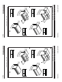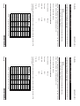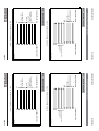
1
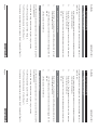
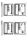
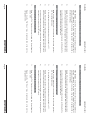
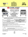
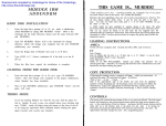
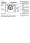
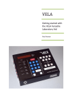
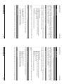
1.0
About this guide
INTRODUCTION
User Guide
INTRODUCTION
1.1
Landmark Technic
1.0
About this guide
User Guide
1.1
This guide gives the information necessary for you to operate a Landmark Technic
Signal Processor. Information regarding installation is contained within the Installation
Guide. More detailed information regarding servicing, repair and calibration of the
processor is contained in the Service Manual.
Landmark Technic
This guide gives the information necessary for you to operate a Landmark Technic
Signal Processor. Information regarding installation is contained within the Installation
Guide. More detailed information regarding servicing, repair and calibration of the
processor is contained in the Service Manual.
1.2
About the Landmark Technic Processor
1.2
The Landmark Technic Signal Processor provides an accurate signal processing unit
for a single LAND System 4 thermometer. Features include:
About the Landmark Technic Processor
The Landmark Technic Signal Processor provides an accurate signal processing unit
for a single LAND System 4 thermometer. Features include:
•
•
•
•
•
•
DIN rail mounting case
Averager, Peak Picker and Track and Hold, for signal processing
Remote input for Track and Hold, Control, Peak Picker Reset
Emissivity/Non-greyness
Alarm output
Retransmission of the thermometer signal output.
•
•
•
•
•
•
Setting up of the processor is performed using a PC and configuration software (see
Section 4).
DIN rail mounting case
Averager, Peak Picker and Track and Hold, for signal processing
Remote input for Track and Hold, Control, Peak Picker Reset
Emissivity/Non-greyness
Alarm output
Retransmission of the thermometer signal output.
Setting up of the processor is performed using a PC and configuration software (see
Section 4).
1.3
Envelope containing this User Guide
Installation Guide
A Landmark Technic Signal Processor
Configuration software on CD and cable
The processor is identified as the Landmark Technic (LM Technic) signal processor.
1.4
•
•
•
•
Nomenclature
Envelope containing this User Guide
Installation Guide
A Landmark Technic Signal Processor
Configuration software on CD and cable
Unpacking the processor
1.3
The package containing the processor will contain the following items:
•
•
•
•
Nomenclature
Page 1
Unpacking the processor
The package containing the processor will contain the following items:
The processor is identified as the Landmark Technic (LM Technic) signal processor.
1.4
Page 1
User Guide
Page 2
no time function
output scaling
current output
alarm
alarm output
RS232
config.
serial i/o
averager
S4
thermometer
peak picker
emissivity
track / hold
LMT010078
Fig. 2 LM Technic - Functional Block Diagram
Landmark Technic
command
input
User Guide
Page 2
no time function
output scaling
current output
alarm
alarm output
RS232
config.
serial i/o
averager
S4
thermometer
peak picker
emissivity
track / hold
LMT010078
Fig. 2 LM Technic - Functional Block Diagram
Landmark Technic
command
input
Landmark Technic
Landmark Technic
Signal retransmission range:
Signal retransmission current:
Signal update rate:
Current output load inc. cable:
Input/output accuracy:
Input/output drift:
Quantisation:
Sampling:
0.200 to 1.000 in 0.001 steps
0.800 to 1.250 in 0.001 steps
Adjustable over thermometer span (min 100°)
0 to 20mA/4 to 20mA
10ms
500 ohms
<0.1% of span
<0.1% of span/°C
16 bit
10ms
Averager adjustment range:
Emissivity setting:
Non-greyness setting:
Signal retransmission range:
Signal retransmission current:
Signal update rate:
Current output load inc. cable:
Input/output accuracy:
Input/output drift:
Quantisation:
Sampling:
0.25°/s to 512°/s in 12 steps
1° steps
0 to 10s in 0.1s steps
0 to 10s in 0.1s steps
Hold/reset
50ms to 512s (63%) in 15 steps
0.200 to 1.000 in 0.001 steps
0.800 to 1.250 in 0.001 steps
Adjustable over thermometer span (min 100°)
0 to 20mA/4 to 20mA
10ms
500 ohms
<0.1% of span
<0.1% of span/°C
16 bit
10ms
User Guide
Emissivity setting:
Non-greyness setting:
50ms to 512s (63%) in 15 steps
Peak Picker decay range:
threshold:
on delay:
off delay:
reset mode:
Controlled by external contact closure/5 to 24V d.c.
10ms
User Guide
Averager adjustment range:
0.25°/s to 512°/s in 12 steps
1° steps
0 to 10s in 0.1s steps
0 to 10s in 0.1s steps
Hold/reset
Track/Hold:
Track/Hold response time:
Hi/Lo
1° steps
50V d.c. at 0.1A
SPECIFICATION
Peak Picker decay range:
threshold:
on delay:
off delay:
reset mode:
Controlled by external contact closure/5 to 24V d.c.
10ms
Alarm:
Trip level:
Relay:
Parameters set by configuration port**
RS232 9600 baud fixed
2.0
Track/Hold:
Track/Hold response time:
Hi/Lo
1° steps
50V d.c. at 0.1A
Configuration:
Configuration port:
SPECIFICATION
Alarm:
Trip level:
Relay:
Parameters set by configuration port**
RS232 9600 baud fixed
2.0
Configuration:
Configuration port:
30V to 50V d.c. at 300mA (including thermometer)
24V to 34V a.c. rms
1g any axis, 10 to 300 Hz
0 to 99% non condensing
IP20
5 to 50°C/41 to 122°F in specification
PSU*:
Environment:
Vibration:
Humidity:
Sealing:
Ambient:
EN61326
30V to 50V d.c. at 300mA (including thermometer)
24V to 34V a.c. rms
1g any axis, 10 to 300 Hz
0 to 99% non condensing
IP20
5 to 50°C/41 to 122°F in specification
EMC:
Page 3
PSU*:
Environment:
Vibration:
Humidity:
Sealing:
Ambient:
EN61326
* LAND DPU recommended
** LAND Configuration software recommended
EMC:
* LAND DPU recommended
** LAND Configuration software recommended
Page 3
User Guide
Landmark Technic
User Guide
Landmark Technic
3.2
3)
2)
1)
Refer to Fig. 4. Insert a screwdriver into the sliding spring catch via the slot
on the underside of the unit.
Removing the unit from a DIN rail
Push the bottom of the unit so that the sliding spring catch clips onto the
DIN rail.
Refer to Fig. 3. Rest the uppermost groove on the rear of the processor
on the top lip of the DIN rail.
Ensure that a suitable DIN rail (DIN EN 50 022) is available and installed
correctly (refer to Appendix).
2)
1)
3.2
3)
2)
1)
Lift the processor off the DIN rail.
Lever the sliding spring catch downwards so that it disengages from the
DIN rail.
Refer to Fig. 4. Insert a screwdriver into the sliding spring catch via the slot
on the underside of the unit.
Removing the unit from a DIN rail
Push the bottom of the unit so that the sliding spring catch clips onto the
DIN rail.
Refer to Fig. 3. Rest the uppermost groove on the rear of the processor
on the top lip of the DIN rail.
Ensure that a suitable DIN rail (DIN EN 50 022) is available and installed
correctly (refer to Appendix).
INSTALLATION AND REMOVAL
1)
Lever the sliding spring catch downwards so that it disengages from the
DIN rail.
3)
Electrical connections
3.0
2)
Lift the processor off the DIN rail.
3.3
INSTALLATION AND REMOVAL
3)
Electrical connections
3.0
3.3
The LM Technic processor is designed to be used in conjunction with the Land DPU
Power Supply Unit.
Fitting the unit onto a DIN rail
The LM Technic processor is designed to be used in conjunction with the Land DPU
Power Supply Unit.
The LMT to DPU wiring interconnections are given in Fig. 5 (overleaf).
3.1
The LMT to DPU wiring interconnections are given in Fig. 5 (overleaf).
The LMT wiring schedule is given in Table 1 (Page 7).
Fitting the unit onto a DIN rail
The LMT wiring schedule is given in Table 1 (Page 7).
The DPU wiring schedule is given in Table 2 (Page 7).
3.1
The DPU wiring schedule is given in Table 2 (Page 7).
Connections to the configuration port are given in Table 3 - Appendix B (Page 22).
The LM Technic processor is designed to be mounted onto a standard DIN rail. To
install the unit:-
Connections to the configuration port are given in Table 3 - Appendix B (Page 22).
Page 4
The LM Technic processor is designed to be mounted onto a standard DIN rail. To
install the unit:-
Page 4
Landmark Technic
Sliding sprin g catch
DIN rail
User Guide
Clip onto DIN rail
LMT010065
LM T 01 00 66
S cre w d riv er
Fig. 3 Installing the LM Technic onto a DIN rail
U se scr ew d riv er
t o u nc lip the
s pr ing la tch
Fig. 4 Removing the LM Technic from a DIN rail
Page 5
Landmark Technic
Sliding spring catch
DIN rail
User Guide
Clip onto DIN rail
LMT010065
LM T 01 00 66
S cre w d riv er
Fig. 3 Installing the LM Technic onto a DIN rail
U se scr ew d riv er
t o u nc lip the
s pr ing la tch
Fig. 4 Removing the LM Technic from a DIN rail
Page 5
2
3
4
Neutral
Live
5
6
Proces sor
Supply (-)
7
8
Processor
Supply (+)
1
2
3
Y BL W
4
5
6
7
R BK G
A
8
B
9
10
11
12
14
15
16
17
Landmark Technic
13
Pow er
+/-
LMT010067
A la rm Co mman d Signa l out
(Twisted pairs)
(Screen ed
tw isted pair)
6 Core Screened Cable to IRT
(Pigtails Maximum Length = 30mm)
Fig. 5 LM Technic and DPU interconnections
NOTE:
The LM Technic processor is designed to work with an a.c.
or d.c. power supply, making pins 16 & 17 on the processor
interchangeable. The output of the DPU power supply is
polarised, with pin 8 the positive and pin 16 the negativ e.
L N 11 12 13 14 15 16
1
User Guide
Page 6
TECHNIC
2
3
4
Neutral
Live
5
6
Proces sor
Supply (-)
7
8
Processor
Supply (+)
1
2
3
Y BL W
4
5
6
7
R BK G
A
8
B
9
10
11
12
14
15
16
17
Landmark Technic
13
Pow er
+/-
LMT010067
A la rm Co mman d Signa l out
(Twisted pairs)
(Screen ed
tw isted pair)
6 Core Screened Cable to IRT
(Pigtails Maximum Length = 30mm)
Fig. 5 LM Technic and DPU interconnections
NOTE:
The LM Technic processor is designed to work with an a.c.
or d.c. power supply, making pins 16 & 17 on the processor
interchangeable. The output of the DPU power supply is
polarised, with pin 8 the positive and pin 16 the negativ e.
L N 11 12 13 14 15 16
1
User Guide
Page 6
TECHNIC
Landmark Technic
W ire Colour
Signal inpu t (-) from therm ome ter
Signal inp ut (+) from therm ome ter
Function
3
2
1
Screen
Wh ite
Blu e
Yellow
W ire Colour
T h ermo mete r pow er su pply (+)
T he rmom eter cable screen
Emissiv ity outp ut (+) to th e th ermom eter
Signal inpu t (-) from therm ome ter
Signal inp ut (+) from therm ome ter
Function
User Guide
Yellow
Emissiv ity outp ut (+) to th e th ermom eter
4
R ed
T h ermom ete r pow er su pply (-)
User Guide
1
Blu e
T he rmom eter cable screen
5
Black
Electrical connections (Continued.....)
2
Wh ite
T h ermo mete r pow er su pply (+)
6
Em issiv ity return (-)
3.3
3
Screen
T h ermom ete r pow er su pply (-)
G reen
Electrical connections (Continued.....)
Landmark Technic
3.3
4
R ed
Em issiv ity return (-)
7
C omm and (-)
C om man d (+)
Alarm R ela y (2)
Alarm R ela y (1)
13
12
11
10
9
Signal out (-)
Signal out (+)
C omm and (-)
C om man d (+)
Alarm R ela y (2)
Alarm R ela y (1)
LM T echn ic T erminal N o.
5
Black
N ot applica ble - do n ot use
LM T echn ic T erminal N o.
6
G reen
12
Signal out (+)
14
Signal out (Scre en)
N ot applica ble - do n ot use
7
13
Signal out (-)
15
Pro cessor p owe r sup ply inpu t (1)
11
M ains in put l iv e
Page 7
8
8
14
Signal out (Scre en)
16
9
15
Pro cessor p owe r sup ply inpu t (1)
Pro cessor p owe r sup ply inpu t (2)
10
16
17
Table 1 Landmark Technic terminal connections
Pro cessor p owe r sup ply inpu t (2)
Table 1 Landmark Technic terminal connections
L
M ains in put n eutra l
Function
M ains in put l iv e
N
DPU out put (+)
Function
L
M ains in put n eutra l
8
DP U
T erm inal N º
N
DPU out put (+)
DPU out put (-)
*** A ll o the r DP U term inals are not use d in th is ap plic atio n ***
16
*** A ll o the r DP U term inals are not use d in th is ap plic atio n ***
Table 2 DPU terminal connections
16
Table 2 DPU Terminal Connections
DPU out put (-)
8
DP U
T erm inal N º
17
Page 7
The Alarm relay contact rating is 50V a.c. or d.c. at 0.1A.
The Alarm output connection schedule is given in Fig. 5 and Table 1.
3.3.1
It is recommended that a twisted pair connection be used.
The Alarm relay contact rating is 50V a.c. or d.c. at 0.1A.
The Alarm output connection schedule is given in Fig. 5 and Table 1.
3.3.1
Landmark Technic
It is recommended that a twisted pair connection be used.
3.3.2
CMD (Command) input connection schedule
The CMD (Command) input connection schedule is given in Fig. 5 and Table 1.
User Guide
3.3.2
CMD (Command) input connection schedule
The CMD (Command) input connection schedule is given in Fig. 5 and Table 1.
The command signal is inactive when the voltage is >3.0V or open circuit (i.e. Track).
The command signal is active when the voltage is <1.5V or short circuit (i.e. Hold).
Landmark Technic
The command signal is inactive when the voltage is >3.0V or open circuit (i.e. Track).
The command signal is active when the voltage is <1.5V or short circuit (i.e. Hold).
The command input can be controlled via a remote switch, as shown in Fig. 6 or via
potential-free contacts as shown in Fig. 7.
User Guide
The command input can be controlled via a remote switch, as shown in Fig. 6 or via
potential-free contacts as shown in Fig. 7.
It is recommended that a twisted pair connection be used.
Alarm output connection schedule
It is recommended that a twisted pair connection be used.
Page 8
Alarm output connection schedule
Page 8
Landmark Technic
Vin
Peak Picker Track & Hold
Track
Remote switch
Switch open
Hold
CMD
+
-
User Guide
Landmark Technic
Vin
Peak Picker Track & Hold
Track
Remote switch
Switch open
Peak Pick
Reset
Potential-free
contacts
Hold
Peak Picker Track & Hold
Track
Peak Pick
Reset
+
-
Vin
Hold
Peak Picker Track & Hold
Track
Peak Pick
Reset
Potential-free
contacts
Short circuit
Open circuit
CMD
+
-
Page 9
User Guide
LMT010069
+
-
Fig. 7 'CMD' (command) input control via potential-free contacts
LMT010070
Note
Potential-free contacts can be replicated by voltage Vin. Where:
>+3.0V = Open circuit
<+1.5V = Short circuit
CMD
Fig. 6 'CMD' (command) input control via a remote switch
Hold
Switch closed
Peak Pick
Reset
Switch closed
Note
Remote switch can be replicated by voltage Vin. Where:
>+3.0V = Switch open
<+1.5V = Switch closed
Vin
Short circuit
Open circuit
Fig. 7 'CMD' (command) input control via potential-free contacts
LMT010070
Note
Potential-free contacts can be replicated by voltage Vin. Where:
>+3.0V = Open circuit
<+1.5V = Short circuit
CMD
Fig. 6 'CMD' (command) input control via a remote switch
Note
Remote switch can be replicated by voltage Vin. Where:
>+3.0V = Switch open
<+1.5V = Switch closed
LMT010069
Page 9
User Guide
Landmark Technic
User Guide
Landmark Technic
3.3.3
Output (Retransmission output) connection schedule
3.3.3
The Output (retransmission output) connection schedule is given in Fig. 5 and
Table 1.
Output (Retransmission output) connection schedule
The Output (retransmission output) connection schedule is given in Fig. 5 and
Table 1.
It is recommended that a screened twisted pair cable is used.
3.3.4
It is recommended that a screened twisted pair cable is used.
3.3.4
The thermometer output connection schedule is given in Fig. 5 and Table 1. It is
recommended that 6-way screened cable is used.
Thermometer output connection schedule
The thermometer output connection schedule is given in Fig. 5 and Table 1. It is
recommended that 6-way screened cable is used.
Page 10
Thermometer output connection schedule
Page 10
Landmark Technic
User Guide
Landmark Technic
Cable connector assembly
User Guide
3.4
Make a note of the connector's orientation.
Cable connector assembly
1)
Unclip the two halves of the connector shell to reveal the terminal block and
the cable tie/clamp bar.
3.4
Make a note of the connector's orientation.
2)
Wire up the connector, remembering the correct orientation of the plug, in
accordance with the relevant cable schedule (see Section 3.3).
The cable connectors for the processor are included in the processor package. Each
cable connector must be correctly wired with the appropriate cable. (Refer to Section
3.3 for the cable schedules).
1)
Unclip the two halves of the connector shell to reveal the terminal block and
the cable tie/clamp bar.
3)
Ensure that the cable outer insulation is held in the clamp bar/cable tie at
the connector and tighten the clamp bar screws/cable tie. Refer to Fig. 8.
The cable connectors for the processor are included in the processor package. Each
cable connector must be correctly wired with the appropriate cable. (Refer to Section
3.3 for the cable schedules).
2)
Wire up the connector, remembering the correct orientation of the plug, in
accordance with the relevant cable schedule (see Section 3.3).
4)
To wire up the connector.
3)
Ensure that the cable outer insulation is held in the clamp bar/cable tie at
the connector and tighten the clamp bar screws/cable tie. Refer to Fig. 8.
Clip together the two halves of the connector shell ensuring that the 'writeon' label is held in place by the shell assembly.
To wire up the connector.
4)
5)
The connector is now ready for use.
Ensure cable's outer insulation
is held in clamp bar/cable tie
Clamp bar
LMT010071
Keep wire length as
short as possible
Clip together the two halves of the connector shell ensuring that the 'writeon' label is held in place by the shell assembly.
Keep wire length as
short as possible
LMT010071
Fig. 8 Correct cable connector wiring arrangement
Page 11
5)
The connector is now ready for use.
Ensure cable's outer insulation
is held in clamp bar/cable tie
Clamp bar
Fig. 8 Correct cable connector wiring arrangement
Page 11
User Guide
Landmark Technic
4.0
Landmark Technic
4.0
When the processor is connected to a System 4 thermometer, the processor must
be configured for use with that particular thermometer and have it's operating
parameters set. The temperature measurement system (i.e. processor and
thermometer) is most easily configured using the LM Technic Configuration Software
and a suitable PC.
User Guide
When the processor is connected to a System 4 thermometer, the processor must
be configured for use with that particular thermometer and have it's operating
parameters set. The temperature measurement system (i.e. processor and
thermometer) is most easily configured using the LM Technic Configuration Software
and a suitable PC.
[It is also possible to use a PC running standard terminal software and an RS232
port to perform the configuration, allowing the individual commands to be used. See
Appendix B]
USING THE CONFIGURATOR
[It is also possible to use a PC running standard terminal software and an RS232
port to perform the configuration, allowing the individual commands to be used. See
Appendix B]
Once configured, the PC can be disconnected and the LM Technic can be left to run
alone, with configuration stored into it's non-volatile memory.
USING THE CONFIGURATOR
Once configured, the PC can be disconnected and the LM Technic can be left to run
alone, with configuration stored into it's non-volatile memory.
4.1
Installation
4.1
Run the file on the CD and follow the Installation Instructions.
Installation
Run the file on the CD and follow the Installation Instructions.
Getting started
4.2
3
Getting started
3
4
4.2
4
5
Fig. 9 Configurator Display
After the power supply has been connected (see Section 3) and switched on, it is
possible to configure the LM Technic using the configuration software. Connect the
configurator cable between the PC and the LM Technic and run the software by
running the .exe file in the installation directory. The configurator software should
respond with the display as shown below.
1
2
5
Fig. 9 Configurator Display
Page 12
After the power supply has been connected (see Section 3) and switched on, it is
possible to configure the LM Technic using the configuration software. Connect the
configurator cable between the PC and the LM Technic and run the software by
running the .exe file in the installation directory. The configurator software should
respond with the display as shown below.
1
2
Page 12
Landmark Technic
User Guide
Title bar indicating configuration file name
A menu bar
A 'live' display showing actual configuration and process data from
the connected processor
A 'configuration area' allowing parameters to be adjusted
Buttons for applying/reading the configuration to/from the processor
Configurator features key:
1
2
3
4
5
4.2.1
New. Use the 'File', 'New', menu to load default data into the configuration
area.
Setting a new configuration in a processor
2)
1)
4.2.1
Thermometer. In the configuration area, select the thermometer type from
the list box to match the thermometer actually connected to the LM Technic.
New. Use the 'File', 'New', menu to load default data into the configuration
area.
Setting a new configuration in a processor
Configuration parameters can be stored to the LM Technic and/or can be downloaded
to a file on the PC for later use. It is possible to use the software without an LM Technic,
however, only file menus will be available.
1)
Thermometer. In the configuration area, select the thermometer type from
the list box to match the thermometer actually connected to the LM Technic.
Configuration parameters can be stored to the LM Technic and/or can be downloaded
to a file on the PC for later use. It is possible to use the software without an LM Technic,
however, only file menus will be available.
2)
4)
3)
Output. The current loop output can be scaled to any temperature range
within the range of the selected thermometer (minimum span 100°). Select
the desired current output range.
Emissivity/Non-Greyness. The menu changes dependent upon the
selected thermometer. If a single colour thermometer has been selected,
enter the desired emissivity for the material being measured. If a 2-colour
ratio thermometer has been selected, enter the non-greyness.
Label. Type in a label for the processor/thermometer (15 characters
maximum).
6)
5)
4)
3)
Alarm. The alarm level can be selected for any temperature within the
range of the thermometer. The alarm can be selected to trip above (High)
or below (Low) this temperature.
Output. The current loop output can be scaled to any temperature range
within the range of the selected thermometer (minimum span 100°). Select
the desired current output range.
Emissivity/Non-Greyness. The menu changes dependent upon the
selected thermometer. If a single colour thermometer has been selected,
enter the desired emissivity for the material being measured. If a 2-colour
ratio thermometer has been selected, enter the non-greyness.
Label. Type in a label for the processor/thermometer (15 characters
maximum).
Note:
It is important that this is done first because it sets defaults and parameter
limits in the other boxes.
5)
Alarm. The alarm level can be selected for any temperature within the
range of the thermometer. The alarm can be selected to trip above (High)
or below (Low) this temperature.
Page 13
Note:
It is important that this is done first because it sets defaults and parameter
limits in the other boxes.
6)
Page 13
2)
1)
4.2.2
9)
8)
7)
4.2.1
Apply. When the required configuration parameters have been entered,
press the 'Apply' button to send the configuration data to the LM Technic.
In the configuration area, adjust parameters as described in 4.2.1.
Read. Use the 'Read' button to load data from the connected processor
into the configuration area.
Editing a configuration in a processor
A summary of the data sent will appear in the live data, confirming that the
data has been received by the LM Technic.
Apply. When the required configuration parameters have been entered,
press the 'Apply' button to send the configuration data to the LM Technic.
Time function. Select from the time function processing available as
required. Depending on the time function selected, a further set of
parameters may need to be chosen. (See Section 5 for details on time
function processing).
Setting a new configuration in a processor (Continued)
4)
3)
2)
1)
4.2.2
9)
8)
7)
4.2.1
Saving/Opening a configuration file
A summary of the data sent will appear in the live data, confirming that the
data has been received by the LM Technic.
Apply. When the required configuration parameters have been entered,
press the 'Apply' button to send the configuration data to the LM Technic.
In the configuration area, adjust parameters as described in 4.2.1.
Read. Use the 'Read' button to load data from the connected processor
into the configuration area.
Editing a configuration in a processor
A summary of the data sent will appear in the live data, confirming that the
data has been received by the LM Technic.
Apply. When the required configuration parameters have been entered,
press the 'Apply' button to send the configuration data to the LM Technic.
Time function. Select from the time function processing available as
required. Depending on the time function selected, a further set of
parameters may need to be chosen. (See Section 5 for details on time
function processing).
Setting a new configuration in a processor (Continued)
Landmark Technic
3)
A summary of the data sent will appear in the live data, confirming that the
data has been received by the LM Technic.
4.2.3
Save. Use the 'File', 'Save' menu to save the data from the configuration
area to a file.
User Guide
4)
Saving/Opening a configuration file
1)
Open. Use the 'File', 'Open' menu to load data from a file into the
configuration area.
Landmark Technic
4.2.3
Save. Use the 'File', 'Save' menu to save the data from the configuration
area to a file.
2)
User Guide
1)
Open. Use the 'File', 'Open' menu to load data from a file into the
configuration area.
Page 14
2)
Page 14
User Guide
TIME FUNCTION PROCESSING
Landmark Technic
5.0
User Guide
TIME FUNCTION PROCESSING
Landmark Technic
5.0
Temperature above which the Peak Picker is active, used in
conjunction with the 'ON' and 'OFF' delay.
Peak Picker
Threshold level:
Time period between the temperature rising above the threshold
level and the Peak Picker function switching on
5.1
Temperature above which the Peak Picker is active, used in
conjunction with the 'ON' and 'OFF' delay.
ON delay:
Time period between the temperature falling below the
threshold level and the Peak Picker function switching off.
Peak Picker
Threshold level:
Time period between the temperature rising above the threshold
level and the Peak Picker function switching on
OFF delay:
5.1
ON delay:
Time period between the temperature falling below the
threshold level and the Peak Picker function switching off.
The Peak Picker function can be used to monitor the highest temperature measured
by the thermometer. This feature is useful especially for moving targets and/or where
the target is obscured partially e.g. a steel slab on a rolling mill where parts of the
surface are covered with scale. The 'clean' area will be at the higher (i.e. true)
temperature. The Peak Picker used in Landmark Technic processors has the
following features. Refer to Fig. 10.
OFF delay:
Mode:
In 'Hold' mode, at the end of the 'OFF' delay, the temperature
output value is held constant until the temperature input next
rises above the threshold level.
The Peak Picker function can be used to monitor the highest temperature measured
by the thermometer. This feature is useful especially for moving targets and/or where
the target is obscured partially e.g. a steel slab on a rolling mill where parts of the
surface are covered with scale. The 'clean' area will be at the higher (i.e. true)
temperature. The Peak Picker used in Landmark Technic processors has the
following features. Refer to Fig. 10.
Mode:
In 'Hold' mode, at the end of the 'OFF' delay, the temperature
output value is held constant until the temperature input next
rises above the threshold level.
Threshold level
'OFF'
Delay
A djustable decay rate
'H old'
m ode
A user-adjustable value at which the stored temperature output
signal decays.
In 'Reset' mode, at the end of the 'OFF' delay, the temperature
output signal falls to 'under-range' until the temperature input
next rises above the threshold level. The Peak Picker can be
'Reset' at any time by using the CMD input. See 3.3.2
'H old'
m ode
'ON '
Delay
'Reset'
m ode
Page 15
L MT 0 10 0 7 2
Fig. 10 Graphical representation of Peak Picker time function
Time
Decay rate:
In 'Reset' mode, at the end of the 'OFF' delay, the temperature
output signal falls to 'under-range' until the temperature input
next rises above the threshold level. The Peak Picker can be
'Reset' at any time by using the CMD input. See 3.3.2
'OFF'
Delay
A djustable decay rate
Threshold level
Temp
A user-adjustable value at which the stored temperature output
signal decays.
'ON '
Delay
'Reset'
m ode
Page 15
L MT 0 10 0 7 2
Fig. 10 Graphical representation of Peak Picker time function
Time
Decay rate:
Temp
Com m and
T im e
User Guide
0V
Track
H old
Track
+V
Landmark Technic
= H old
= T rack
= T rack
= H old
H old
Com m and signal = Closure of po tential-free contact s, s/c
+5V
T T L lev el (0 to 5 V)
+24V
or 0 to 24 V
0V
LM T010073
LMT010074
Fig. 11 Graphical representation of Track and Hold time function
Fast averager
response speed
Fig. 12 Graphical representation of Averager time function
Slow averager
response speed
Time
Page 16
User Guide
T im e
Com m and
Track
H old
Track
Fast averager
response speed
+V
LM T010073
Landmark Technic
H old
Hol d
T rack
T rack
H old
Fig. 12 Graphical representation of Averager time function
Slow averager
response speed
Time
Page 16
LMT010074
Fig. 11 Graphical representation of Track and Hold time function
Com m and signal = Closure of potential-free contacts, s/c =
+5V =
T T L lev el (0 to 5V)
+24V =
or 0 to 24V
0V =
0V
Temp
Temp
Temp
Temp
User Guide
Landmark Technic
User Guide
5.2
Landmark Technic
5.2
Refer to Fig. 11. The Track and Hold time function is useful especially for measuring
intermittent processes e.g. items on a conveyor belt. The presence of a 'hot' object
can be used to activate the 'Track' function, which causes the output to display the
temperature of the object. When the object moves from the measurement area, the
'Track' function can be switched off and the temperature value held until the next 'hot'
object appears.
Track and Hold
Refer to Fig. 11. The Track and Hold time function is useful especially for measuring
intermittent processes e.g. items on a conveyor belt. The presence of a 'hot' object
can be used to activate the 'Track' function, which causes the output to display the
temperature of the object. When the object moves from the measurement area, the
'Track' function can be switched off and the temperature value held until the next 'hot'
object appears.
The Track and Hold function is controlled via the CMD (Command) input. See 3.3.2
Track and Hold
The Track and Hold function is controlled via the CMD (Command) input. See 3.3.2
Averager
Refer to Fig. 12. The Averager time function can be used to 'smooth' the temperature
output signal in relation to the temperature input. The averager response can be
adjusted to suit your application. With a fast response speed, the temperature output
signal tracks the input signal closely, any rapid fluctuations in the input are reflected
in the output. With a slow response speed, the temperature output signal is much
smoother, displaying more the 'trend' of the input signal rather than rapid changes.
5.3
Page 17
User Guide
Landmark Technic
User Guide
Landmark Technic
6.0
A mber
Colour
Volatile
Configuration
Test Mode
Indication
Flashing
Green
Flashing
Am ber
A mber
Colour
OK
Configurator
Connected
Volatile
Configuration
Test Mode
Indication
LED INDICATORS
6.0
LED's A and B on the Landmark Technic give visual identification of internal
operations of the unit. The following table lists the indications in order of precedence.
Flashing
Am ber
Configurator
Connected
Green
LED INDICATORS
LED's A and B on the Landmark Technic give visual identification of internal
operations of the unit. The following table lists the indications in order of precedence.
LED A
Flashing
Green
OK
Flashing
Am ber
Am ber
Flashing
Red
Red
Colour
Comm and Input
Active
Obscured**
Clipping*
Alarm
Sensor Fail***
Indication
Flashing
Green
Flashing
Am ber
Am ber
Flashing
Red
Red
Colour
OK
Comm and Input
Active
Obscured**
Clipping*
Alarm
Sensor Fail***
Indication
LED B
Flashing
Green
Green
* Clipping = Unstable Input To
Averaging Function
** Unclamped Ratio Pyrom eters only
*** Clam ped Pyrom eters Only
OK
* Clipping = Unstable Input To
Averaging Function
** Unclamped Ratio Pyrom eters only
*** Clam ped Pyrom eters Only
Green
LED B
Green
Page 18
LED A
Page 18
Landmark Technic
User Guide
Landmark Technic
MAINTENANCE
User Guide
The Landmark Technic Processor is designed to be virtually maintenance free, but
calibration checks are highly recommended at periods of not more than 1 year.
For details on Landmark Technic calibration, please contact Land Infrared Calibration
Services.
7.0
Page 19
MAINTENANCE
The Landmark Technic Processor is designed to be virtually maintenance free, but
calibration checks are highly recommended at periods of not more than 1 year.
For details on Landmark Technic calibration, please contact Land Infrared Calibration
Services.
7.0
Page 19
User Guide
Page 20
Landmark Technic
User Guide
Page 20
Landmark Technic
Landmark Technic
/0
in
.71
in
/0
27
m
m
/1
.3 8
. 06
in
/1
.0
in
6in
User Guide
Length
Plain (1.5mm / 0.06in)
0.5m
1.0m
Length
Landmark Technic
7.5 mm / 0.30i n
RS Stock No.
176-674
176-680
RS Stock No.
0.5m
1.0m
Plain (1.0mm / 0.04in)
176-652
176-668
mm
25
n
9 8i
/ 0.
27m
m
/1
.38
in
in
Length
.9 8
RS Stock No.
/0
6in
0.5m
1.0m
mm
.0
in
176-696
176-703
25
.38
m
/1
27
m
m
RS Stock No.
0.5m
1.0m
Length
6.3
mm
m
.25
m
/0
6 .3
in
mm
18
/0
.2 5
in
/0
18
m
/0
1 in
.7
in
.71
m
27
.0
in
/1
.3 8
mm
/1
. 06
in
.38
in
/1
35
mm
/1
27
mm
35
mm
Fig. 9 DIN rail dimensions
424-131
606-838
Punched (1.0mm / 0.04in)
35
m
/1
Punched (1.5mm / 0.06in)
35
mm
/1
.06
in
APPENDIX A - DIN RAIL SPECIFICATION
.25
mm
18
m
35
mm
APPENDIX A - DIN RAIL SPECIFICATION
6.3
mm
/0
m
m
1 in
.7
DIN rail specification. DIN EN 50 022
n
9 8i
/ 0.
6 .3
m
/0
.2 5
in
18
/1
.38
in
27
mm
/1
15mm / 0.59in
DIN rail specification. DIN EN 50 022
mm
25
/1
.06
in
/1
.38
in
Length
35
mm
15 mm / 0 .59 in
27m
m
35
mm
in
Length
Punched (1.5mm / 0.06in)
.9 8
6in
RS Stock No.
/0
.0
.38
in
/1
0.5m
1.0m
mm
/1
m
176-696
176-703
25
m
27
m
35
m
RS Stock No.
0.5m
1.0m
Punched (1.0mm / 0.04in)
424-131
606-838
LMT010077
Page 21
7.5mm / 0.30 in
15 mm / 0 .59 in
Fig. 9 DIN rail dimensions
7.5mm / 0.30 in
15mm / 0.59in
7.5 mm / 0.30i n
6in
User Guide
RS Stock No.
0.5m
1.0m
Length
Plain (1.5mm / 0.06in)
176-674
176-680
RS Stock No.
0.5m
1.0m
Length
Plain (1.0mm / 0.04in)
176-652
176-668
LMT010077
Page 21
Landmark Technic
APPENDIX B - SERIAL COMMUNICATIONS SET-UP
User Guide
APPENDIX B - SERIAL COMMUNICATIONS SET-UP
The Landmark Technic configurator port can be used for communication between the
processor and either a terminal or a computer.
Landmark Technic
The Landmark Technic configurator port can be used for communication between the
processor and either a terminal or a computer.
NOTE
It is recommended that configuration is normally performed using
the configuration software provided.
User Guide
NOTE
It is recommended that configuration is normally performed using
the configuration software provided.
RS232C
RS232C is standard and compatible with either terminals or computers which
allows communications with a single processor only.
Mode selection:
9600
RS232C is standard and compatible with either terminals or computers which
allows communications with a single processor only.
RS232C
Baud rate:
8 bits
RS485 - contact Land Infrared.
Mode selection:
9600
Data bits:
None
RS485 - contact Land Infrared.
Baud rate:
8 bits
Parity:
Serial Communications specification
Data bits:
None
Serial Communications specification
Parity:
1
Black
Colour
5
D Type Pin #
232 Cable (031.085)
Stop bits:
1
Function
Stop bits:
232 Cable (031.085)
The RS232 serial communications output connection schedules are given in Fig.
5 and Table 3.
Function
Configurator
Connector Pin #
0V
5
D Type Pin #
1
Black
0V
Colour
1
3
Configurator
Connector Pin #
2
-
White
-
Yellow
-
-
232TX
485(Y)
-
232RX
4
485(Z)
-
2
5
Do not use
3
-
6
3
-
-
2
-
-
-
White
485(Y)
-
-
Yellow
4
485(Z)
-
-
232TX
5
Do not use
7
485(A)
Do not use
232RX
6
8
2
7
-
-
-
-
-
485(B)
-
9
485(A)
-
Table 3 Configurator terminal connections
-
Do not use
485(B)
Table 3 Configurator terminal connections
9
8
3
Page 22
The RS232 serial communications output connection schedules are given in Fig.
5 and Table 3.
Page 22
Serial Communications protocol
Landmark Technic
B1
User Guide
Serial Communications protocol
RS232C read data
Landmark Technic
B1
B1.1
B1.2
RS232C set data
User Guide
Landm ark Technic
x
Value of requested
x parameter
or
x (ASCII)
x
CR
LF
LMT010075
Page 23
LMT010076
Landm ark Technic
Fig. 13 RS232C mode READ protocol
R
A
Parameter value x
being requested
(ASCII) x
x
CR
Computer/Terminal
RS232C read data
Landm ark Technic
LMT010075
x
Value of requested
x parameter
or
x (ASCII)
x
CR
LF
B1.1
Computer/Terminal
RS232C set data
Fig. 13 RS232C mode READ protocol
R
A
Parameter value x
being requested
(ASCII) x
x
CR
B1.2
Computer/Term inal
S
A
Parameter value x
being modified x
(ASCII)
x
Space
Landm ark Technic
Computer/Term inal
S
A
Parameter value x
being modified x
(ASCII)
x
Space
x
New parameter x
value (ASCII)
x
x
CR
LMT010076
Fig. 14 RS232C mode WRITE protocol
x
New parameter x
value (ASCII) x
x
CR
Fig. 14 RS232C mode WRITE protocol
Page 23
User Guide
Landmark Technic
User Guide
RATMP [enter]
Landmark Technic
Type at the terminal:
Read mode
Always A
Command to report the temperature
Press terminal enter key
RS232C examples
Breakdown:
R
A
TMP
[enter]
Temperature in degrees
Breakdown:
Type at the terminal:
S
A
EMS
∆
500
[enter]
SAEMS 500 [enter]
NOTE
In general, changed parameters are stored in volatile memory
until an explicit save command is sent (see MEM in Section
B1.4).
Set mode
Always A
Command to work on the emissivity value
(Space)
New value
Press terminal enter key
None
Page 24
Reply:
To set the emissivity to 0.500
1000
B1.3
RATMP [enter]
RS232C examples
Read mode
Always A
Command to report the temperature
Press terminal enter key
SAEMS 500 [enter]
Reply:
B1.3
Type at the terminal:
R
A
TMP
[enter]
Temperature in degrees
To read the temperature
Breakdown:
1000
To read the temperature
Reply:
Type at the terminal:
S
A
EMS
∆
500
[enter]
To set the emissivity to 0.500
Breakdown:
None
NOTE
In general, changed parameters are stored in volatile memory
until an explicit save command is sent (see MEM in Section
B1.4).
Set mode
Always A
Command to work on the emissivity value
(Space)
New value
Press terminal enter key
Reply:
Page 24
Menu t itle text
Range
User Guide
Limits and units
deter mined by
irt_type value
Initially s et to 1
Units are s
Initially s et to 12
13 to 15 not
us ed
Units ar e °/s
Seconds
Seconds
4 = 2.0
5 = 4.0
6 = 8.0
7 = 16.0
8 = 32.0
9 = 64.0
10 = 128
11 = 256
12 = 512
0 = 0.00
1 = 0.25
2 = 0.5
3 = 1.0
e.g. ; 32 = 3.2s
e.g. ; 69 = 6.9s
Us e of corr ect
parameter is
deter mined by
irt_type value.
Lis t of available
thermometers
obtained us ing
IFO command.
Note Changing
IRT s ets default
parameters in
other places
Co mments
e.g ; 0.200 = 200
Default
1000
Increment
1
Max
1000
Min
Serial Port Parameters
Landmark Technic
B1.4
Name
200
Thermometer
type
Emis s ivity
1000
IRT
EMS
1
irt_tmin
0
100
0
1
= value in
degr ees
e.g. ; 1051C
0
1250
1
800
3
1
1
1
1
1
1
0 = None
1 = Averager
2 = Peak pick er
3 = Track & hold
N on greynes s
0
1
ir t_tmax
100
100
15
15
0
NGR
Time function
0
irt_tmin
0
0
0
0
0 = Res et
1 = Hold
e.g. 1.103 =
1103
TFN
PPM
Peak pick er
mode
PON
Peak pick er
ON delay
PPT
POF
Peak pick er
OFF delay
Peak pick er
thres hold
PPD
Averager
res pons e time
Peak Pick er
decay rate
AVR
0 = 0.00
1 = 0.05
2 = 0.1
3 = 0.15
4 = 0.25
5 = 0.5
6 = 1.0
7 = 2.0
8 = 4.0
9 = 8.0
10 = 16.0
11 = 32.0
12 = 64.0
13 = 128
14 = 256
15 = 512
Page 25
Menu t itle text
User Guide
Us e of corr ect
parameter is
deter mined by
irt_type value.
Lis t of available
thermometers
obtained us ing
IFO command.
Note Changing
IRT s ets default
parameters in
other places
Co mments
e.g ; 0.200 = 200
Default
1000
e.g. 1.103 =
1103
Increment
1
1000
Range
1000
1
Max
200
1250
Min
Serial Port Parameters
Landmark Technic
B1.4
Name
Emis s ivity
800
Thermometer
type
EMS
N on greynes s
0
IRT
NGR
1
0 = None
1 = Averager
2 = Peak pick er
3 = Track & hold
3
0 = Res et
1 = Hold
0
0
Time function
1
Limits and units
deter mined by
irt_type value
1
Seconds
0
TFN
PPM
e.g. ; 69 = 6.9s
= value in
degr ees
e.g. ; 1051C
Seconds
irt_tmin
0
e.g. ; 32 = 3.2s
1
1
100
irt_tmin
100
1
Peak pick er
mode
0
100
PPT
0
Initially s et to 1
Units are s
Initially s et to 12
Units ar e °/s
13 to 15 not
us ed
4 = 2.0
5 = 4.0
6 = 8.0
7 = 16.0
8 = 32.0
9 = 64.0
10 = 128
11 = 256
12 = 512
0 = 0.00
1 = 0.25
2 = 0.5
3 = 1.0
ir t_tmax
PON
Peak pick er
ON delay
0
Peak pick er
thres hold
POF
1
1
15
1
0
15
Peak pick er
OFF delay
0
PPD
Averager
res pons e time
Peak Pick er
decay rate
AVR
0 = 0.00
1 = 0.05
2 = 0.1
3 = 0.15
4 = 0.25
5 = 0.5
6 = 1.0
7 = 2.0
8 = 4.0
9 = 8.0
10 = 16.0
11 = 32.0
12 = 64.0
13 = 128
14 = 256
15 = 512
Page 25
User Guide
Menu title text
Max
Range
Min
1
irt_max
0
irt_min
1
<
irt_tmax
<
irt_tmax
-100
Increment
Default
LM
Technic
irt_tmin
irt_tmax
1
irt_max
1
1
5
5
1
1
1
Serial Port Parameters (Continued)
Name
Mode
B1.4
A1M
Level
Signal output
type
A1L
OPT
Signal output
Tmax (20mA)
>
irt_tmin
+100
0
OMX
>
irt_tmin
Channel label
Signal output
Tmin (mA)
OMN
LBL
Full
character set
Landmark Technic
Comments
User Guide
Min
Max
Range
Increment
Default
Serial Port Parameters (Continued)
Menu title text
B1.4
Name
1
irt_max
1
1
1
1
1
1
irt_max
0
0
irt_min
Mode
Level
A1M
value in degrees
A1L
0 = Low
1 = High
OPT
irt_tmax
Signal output
type
<
irt_tmax
5
0 = 0 to 20mA
1 = 4 to 20mA
Signal output
Tmax (20mA)
irt_tmin
OMX
= value in degrees
5
>
irt_tmin
+100
OMN
>
irt_tmin
Additional limit
on value ensures
(t_max - t_min)
= >100°
1
Signal output
Tmin (mA)
= value in degrees
Channel label
Landmark Technic
Additional limit
on value ensures
(t_max - t_min)
= >100°
Comments
value in degrees
0 = Low
1 = High
= value in degrees
0 = 0 to 20mA
1 = 4 to 20mA
= value in degrees
0 = not set
1 = set
LBL
Read only
= character string
(15 characters
long)
Alarm 1 status
0 = not set
1 = set
LM
Technic
A1S
Read only
Full
character set
<
irt_tmax
-100
= character string
(15 characters
long)
0 = not set
1 = set
Obscuration
status
Read only
OBS
0 = not set
1 = set
Alarm 1 status
A1S
0 = not set
1 = set
Read only
Read only
Read only
Obscuration
status
OBS
OVR
Over range
status
Read only
OVR
TMP
0 = not set
1 = set
Over range
status
Temperature in
degrees +
unitsvdr
Read only
TMP
Temperature
reading
Temperature in
degrees +
unitsvdr
Temperature
reading
0 = not set
1 - set
Under range
status
Page 26
UDR
Read only
0 = not set
1 - set
Under range
status
Read only
UDR
Page 26
Status flags
Menu title text
Min
0xFFFF
Max
Range
0x0000
0x0001
Default
Comments
Read Onl y
1
0
X
X
X
Bit
2
Fu nction
User Guide
Set
OK
OK
Not active
Active
OK
Active
Under range
Active
OK
Command I/P
4
Ove r range
Active
3
5
Active
OK
Obscure d *
Active
OK
Clippi ng **
Sensor fail ***
Active
6
8
Alarm 1
7
9
X
X
X
X
12
X
10
13
X
11
14
Uncl amped
Ratio IRT Onl y
Only
Clamped IRT
Mode Only
Average
15
*
**
***
Read response 0000 RAM = FLASH
0 = refreshON, 1=refreshOFF
0000
Read Onl y
0 = processor bui ld info
0001
0001
Read Onl y
9999
Read response 0001 RAM = FLASH
Flag is set w hen confi guration is volati le
i .e. w ill be lost at power down
Set arg 1101 Save RAM> FLASH
Set arg 9999 Move FLASH>RAM
0001
1
See also REFresh
00 00
3
continuous refresh FLASH to RAM
0
0000
Increment
Serial Port Parameters (Continued)
Landmark Technic
B1.4
Name
FLG
Memory
Refresh
MEM
REF
Information
function
IFO
2 = configuration report
1 = thermo meter list
3 = contact information
multi l ine repl y with [start] and [e nd]
deli mitters
Page 27
Status flags
Menu title text
Min
0xFFFF
Max
Increment
0x0001
Default
Comments
Read Onl y
6
5
4
3
Sensor fail ***
Clippi ng **
Obscure d *
Ove r range
Under range
Command I/P
Fu nction
Active
Active
Active
Active
Active
Active
Active
Set
OK
OK
OK
OK
OK
OK
Not active
User Guide
7
Alarm 1
Bit
8
X
X
9
X
X
10
X
0
11
X
X
12
X
2
13
Ratio IRT Onl y
Only
Clamped IRT
Mode Only
Average
1
14
X
Uncl amped
15
*
**
***
Read response 0001 RAM = FLASH
Read response 0000 RAM = FLASH
Flag is set w hen confi guration is volati le
0 = refreshON, 1=refreshOFF
0000
Read Onl y
0 = processor bui ld info
0001
0001
Read Onl y
9999
Set arg 1101 Save RAM> FLASH
i .e. w ill be lost at power down
Set arg 9999 Move FLASH>RAM
0001
1
See also REFresh
00 00
3
2 = configuration report
1 = thermo meter list
continuous refresh FLASH to RAM
0
0000
0x0000
Range
Serial Port Parameters (Continued)
Landmark Technic
B1.4
Name
FLG
Memory
Refresh
function
REF
Information
MEM
IFO
multi l ine repl y with [start] and [e nd]
3 = contact information
deli mitters
Page 27
Landmark Technic
B1.5
User Guide
B1.5
Command response time
Landmark Technic
Command response time
This is the time taken between the end of the last character of a command and the
beginning of the first character of the reply. This time is independent of the selected
baud rate.
User Guide
This is the time taken between the end of the last character of a command and the
beginning of the first character of the reply. This time is independent of the selected
baud rate.
All commands are serviced within 20ms.
System Communications Timing Data
All commands are serviced within 20ms.
Command reply time
System Communications Timing Data
Command reply time
Inter-command timing
This is the time taken by the LM Technic reply. It is directly related to the selected baud
rate and the number of characters in the reply.
Inter-command timing
This is the time between the end of the last character of a command received by the
LM Technic and the end of the last character of its response i.e. the period when the
LM Technic is unable to take a command because it is still processing a previous one.
This is the time taken by the LM Technic reply. It is directly related to the selected baud
rate and the number of characters in the reply.
This is the time between the end of the last character of a command received by the
LM Technic and the end of the last character of its response i.e. the period when the
LM Technic is unable to take a command because it is still processing a previous one.
This is the command response time + command reply time.
NOTE
Use of the IFO command, which will involve long replies, will
disrupt internal timing and affect time function processing.
This is the command response time + command reply time.
For RS232C at 9600 baud, assuming a reply of 20 characters maximum, the
inter-command time is 41ms.
NOTE
Use of the IFO command, which will involve long replies, will
disrupt internal timing and affect time function processing.
For RS232C at 9600 baud, assuming a reply of 20 characters maximum, the
inter-command time is 41ms.
Cable Lengths
9600 baud, 50m (EIA RS232C standard)
Cable Lengths
Page 28
RS232C
The maximum cable lengths are, to a great extent, dependent on baud rate and cable
type. Generally a lower baud rate will give reliable communications over a longer
length of a given cable type.
9600 baud, 50m (EIA RS232C standard)
The maximum cable lengths are, to a great extent, dependent on baud rate and cable
type. Generally a lower baud rate will give reliable communications over a longer
length of a given cable type.
RS232C
Page 28
instruments international
abc
instruments international
abc
TECHNIC
Publication Nº: LMT198.213
Issue: A 04/03
Land Instruments International
10 Friends Lane
Newtown, PA 18940-1804, U.S.A.
Telephone: (215) 504-8000
Facsimile: (215) 504-0879
Email: [email protected]
Internet: www.landinstruments.net
TECHNIC
© Land Instruments International, 2003
Land Instruments International
Dronfield S18 1DJ
England
Telephone: (01246) 417691
Facsimile: (01246) 410585
Email: [email protected]
Internet: www.landinst.com
User Guide
Publication Nº: LMT198.213
Issue: A 04/03
Land Instruments International
10 Friends Lane
Newtown, PA 18940-1804, U.S.A.
Telephone: (215) 504-8000
Facsimile: (215) 504-0879
Email: [email protected]
Internet: www.landinstruments.net
User Guide
Land Instruments International
Dronfield S18 1DJ
England
Telephone: (01246) 417691
Facsimile: (01246) 410585
Email: [email protected]
Internet: www.landinst.com
© Land Instruments International, 2003
Landmark Technic
User Guide
Landmark Technic
User Guide
The Quality Management System of Land Instruments International Ltd. is
approved to BS EN ISO9001:2000 for the design and manufacture, stockholding,
in-house repair and site servicing of non contact temperature measuring
instrumentation. Associated software designed and developed in accordance
with TickIT.
ABC abcdefg
The Quality Management System of Land Instruments International Ltd. is
approved to BS EN ISO9001:2000 for the design and manufacture, stockholding,
in-house repair and site servicing of non contact temperature measuring
instrumentation. Associated software designed and developed in accordance
with TickIT.
Calibration certificates are available from our UKAS accredited Calibration
Laboratory No. 0034. The Land calibration laboratory complies with the
requirements of the international standard BS EN ISO/IEC 17025.
ABC abcdefg
Calibration certificates are available from our UKAS accredited Calibration
Laboratory No. 0034. The Land calibration laboratory complies with the
requirements of the international standard BS EN ISO/IEC 17025.
Landmark ® is a registered trademark.
Land Landmark products comply with current European
directives relating to electromagnetic compatibility and safety.
(EMC directive 89/336/EEC; Low voltage directive 73/23/EEC)
Landmark ® is a registered trademark.
Land Landmark products comply with current European
directives relating to electromagnetic compatibility and safety.
(EMC directive 89/336/EEC; Low voltage directive 73/23/EEC)
All packaging material used for this product is 100% recyclable.
Quality Assurance
All packaging material used for this product is 100% recyclable.
Quality Assurance
Landmark Technic
User Guide
Landmark Technic
SAFETY INFORMATION
User Guide
IEC 417, No. 5033
IEC 417, No. 5032
IEC 417, No. 5031
Three-phase alternating
current
Both direct and alternating
current
Alternating current
Direct current
IEC 417, No. 5017
IEC 617-2, No. 02-02-06
IEC 417, No. 5033
IEC 417, No. 5032
IEC 417, No. 5031
Protective
terminal
Earth (ground) terminal
Three-phase alternating
current
Both direct and alternating
current
Alternating current
Direct current
Description
IEC 617-2, No. 02-02-06
Earth (ground) terminal
IEC 417, No. 5019
Frame or chassis terminal
Publication
IEC 417, No. 5017
Protective
terminal
IEC 417, No. 5020
Equipotentiality
Symbol
IEC 417, No. 5019
Frame or chassis terminal
IEC 417, No. 5021
On (Supply)
Description
IEC 417, No. 5020
Equipotentiality
IEC 417, No. 5007
Off (Supply)
Publication
IEC 417, No. 5021
On (Supply)
IEC 417, No. 5008
SAFETY INFORMATION
Symbol
IEC 417, No. 5007
Off (Supply)
Safety Information
conductor
IEC 417, No. 5008
IEC 417, No. 5172
Equipment
protected
throughout by double
insulation or reinforced
insulation (equivalent to
Class II of IEC 536)
conductor
IEC 417, No. 5172
Equipment
protected
throughout by double
insulation or reinforced
insulation (equivalent to
Class II of IEC 536)
Safety Information
User Guide
User Guide
Description
ISO 3864, No. B.3.6
Publication
Caution
Caution, risk of electric
shock
Description
Landmark Technic
Publication
Caution, risk of electric
shock
ISO 3864, No. B.3.1
Landmark Technic
ISO 3864, No. B.3.6
Caution
SAFETY INFORMATION (Continued)
ISO 3864, No. B.3.1
BS EN 100015
Observe precautions for
handling
electrostatic
discharge sensitive devices
Symbol
BS EN 100015
Observe precautions for
handling
electrostatic
discharge sensitive devices
Warning, laser radiation
Refer to the Operating
Instructions.
Warning, laser radiation
BS EN 60825-1, 1994
Refer to the Operating
Instructions.
Safety Information
BS EN 60825-1, 1994
SAFETY INFORMATION (Continued)
Symbol
Safety Information
Landmark Technic
User Guide
Blank
Landmark Technic
User Guide
Blank
User Guide
CONTENTS
Landmark Technic
User Guide
SAFETY INFORMATION
QUALITY ASSURANCE
CONTENTS (THIS PAGE)
SAFETY INFORMATION
QUALITY ASSURANCE
CONTENTS
CONTENTS (THIS PAGE)
PREFACE
Landmark Technic
1
1
1
1
1
1.1
1.2
1.3
1.4
3
INTRODUCTION
SPECIFICATION
4
1.0
PREFACE
1
1
1
1
1
2.0
INSTALLATION AND REMOVAL
INTRODUCTION
1.1
1.2
1.3
1.4
3
3.0
1.0
SPECIFICATION
4
12
12
4
4
4
11
TIME FUNCTION PROCESSING
4.1
Getting started
USING THE CONFIGURATOR
3.1
3.2
3.3
3.4
Peak Picker
Track and Hold
Averager
15
17
17
15
12
12
4
4
4
11
About this Guide
About the Landmark Technic Processor
Unpacking the processor
Nomenclature
2.0
INSTALLATION AND REMOVAL
15
5.1
5.2
5.3
18
About this Guide
About the Landmark Technic Processor
Unpacking the processor
Nomenclature
3.0
USING THE CONFIGURATOR
3.1
3.2
3.3
3.4
Getting started
15
17
17
LED INDICATORS
19
5.0
Fitting the unit onto a DIN rail
Removing the unit from a DIN rail
Electrical connections
Cable connector assembly
TIME FUNCTION PROCESSING
4.1
Peak Picker
Track and Hold
Averager
6.0
MAINTENANCE
Fitting the unit onto a DIN rail
Removing the unit from a DIN rail
Electrical connections
Cable connector assembly
5.1
5.2
5.3
18
7.0
4.0
LED INDICATORS
19
20
4.0
6.0
MAINTENANCE
APPENDIX A - DIN RAIL SPECIFICATIONS
5.0
7.0
20
Serial Communications protocol
23
APPENDIX A - DIN RAIL SPECIFICATIONS
Contents
B1
22
23
APPENDIX B - SERIAL COMMUNICATIONS SET-UP
Serial Communications protocol
22
B1
APPENDIX B - SERIAL COMMUNICATIONS SET-UP
Contents
Landmark Technic
User Guide
Blank
Landmark Technic
User Guide
Blank
User Guide
PREFACE
Preface
Fig. 1 Landmark Technic
Landmark Technic
User Guide
PREFACE
Preface
Fig. 1 Landmark Technic
Landmark Technic
Landmark Technic
User Guide
Blank
Landmark Technic
User Guide
Blank