1
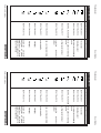
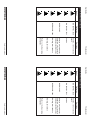
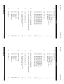
Land Infrared
10 Friends Lane
Newtown, PA 18940-1804
U.S.A.
Telephone: (215) 504 8000
Facsimile:
(215) 504 0879
Email:
[email protected]
Thermometer
Land Infrared
Dronfield
S18 1DJ
England
Telephone: (01246) 417691
Facsimile:
(01246) 410585
Email: [email protected]
Part Nº 198.006 [Publication Nº S4970333]
Issue B 03/02
Thermometer
Land Infrared
10 Friends Lane
Newtown, PA 18940-1804
U.S.A.
Telephone: (215) 504 8000
Facsimile:
(215) 504 0879
Email:
[email protected]
© Land Infrared, 2002
User Guide
Land Infrared
Dronfield
S18 1DJ
England
Telephone: (01246) 417691
Facsimile:
(01246) 410585
Email: [email protected]
Part Nº 198.006 [Publication Nº S4970333]
Issue B 03/02
User Guide
© Land Infrared, 2002
User Guide
Thermometer
User Guide
Thermometer
The Quality Management System of Land Instruments International Ltd. is
approved to BS EN ISO9001:2000 for the design and manufacture, stockholding,
in-house repair and site servicing of non contact temperature measuring
instrumentation. Associated software designed and developed in accordance
with TickIT.
ABC abcdefg
The Quality Management System of Land Instruments International Ltd. is
approved to BS EN ISO9001:2000 for the design and manufacture, stockholding,
in-house repair and site servicing of non contact temperature measuring
instrumentation. Associated software designed and developed in accordance
with TickIT.
Calibration certificates are available from our UKAS accredited Calibration
Laboratory No. 0034. The Land calibration laboratory complies with the
requirements of the international standard BS EN/IEC 17025.
ABC abcdefg
Calibration certificates are available from our UKAS accredited Calibration
Laboratory No. 0034. The Land calibration laboratory complies with the
requirements of the international standard BS EN/IEC 17025.
of
Quality Assurance
trademark
This product complies with current European directives
relating to electromagnetic compatibility and safety (EMC
directive 89/336/EEC; Low voltage directive 73/23/EEC).
Landmark ® is a registered
Land Instruments International Ltd.
This product complies with current European directives
relating to electromagnetic compatibility and safety (EMC
directive 89/336/EEC; Low voltage directive 73/23/EEC).
of
All packaging material used for this product is 100%
trademark
All packaging material used for this product is 100%
Landmark ® is a registered
Land Instruments International Ltd.
Quality Assurance
Thermometer
SAFETY INFORMATION
Symbol
Safety Information
User Guide
Thermometer
SAFETY INFORMATION
User Guide
Direct current
Description
IEC 417, No. 5031
Alternating current
Publication
Direct current
IEC 417, No. 5032
Both direct and alternating
current
Symbol
IEC 417, No. 5031
Alternating current
IEC 417, No. 5033
Description
IEC 417, No. 5032
Both direct and alternating
current
Publication
IEC 417, No. 5033
IEC 417, No. 5020
IEC 417, No. 5019
IEC 417, No. 5017
Equipotentiality
Frame or chassis terminal
Protective
terminal
Earth (ground) terminal
IEC 417, No. 5007
IEC 417, No. 5021
IEC 417, No. 5020
IEC 417, No. 5019
IEC 417, No. 5017
Off (Supply)
On (Supply)
Equipotentiality
Frame or chassis terminal
Protective
terminal
Earth (ground) terminal
IEC 617-2, No. 02-02-06 Three-phase alternating
current
IEC 417, No. 5021
On (Supply)
IEC 417, No. 5008
IEC 617-2, No. 02-02-06 Three-phase alternating
current
IEC 417, No. 5007
Off (Supply)
conductor
IEC 417, No. 5008
IEC 417, No. 5172
Equipment
protected
throughout by double
insulation or reinforced
insulation (equivalent to
Class II of IEC 536)
conductor
IEC 417, No. 5172
Equipment
protected
throughout by double
insulation or reinforced
insulation (equivalent to
Class II of IEC 536)
Safety Information
User Guide
User Guide
Publication
Caution, risk of electric
shock
Description
Thermometer
Description
ISO 3864, No. B.3.6
Caution
Thermometer
Publication
Caution, risk of electric
shock
ISO 3864, No. B.3.1
SAFETY INFORMATION (Continued)
ISO 3864, No. B.3.6
Caution
Observe precautions for
handling electrostatic
discharge sensitive devices
Symbol
ISO 3864, No. B.3.1
BS EN 100015
Warning, laser radiation
SAFETY INFORMATION (Continued)
Symbol
BS EN 100015
Observe precautions for
handling electrostatic
discharge sensitive devices
BS EN 60825: 1992
Warning, laser radiation
Warning, hot surface
BS EN 60825: 1992
Warning, hot surface
Refer to the Operating
Instructions.
Safety Information
Refer to the Operating
Instructions.
Safety Information
Thermometer
Blank
User Guide
Thermometer
Blank
User Guide
User Guide
1.0
2.0
3.0
4.0
5.0
6.0
Contents
Thermometer
1
1
1
1
1
3
INTRODUCTION
1.1
1.2
1.3
1.4
1.5
4
About this guide
About the thermometer
About System 4
Unpacking the thermometer
Nomenclature
SPECIFICATIONS
4
5
6
7
8
9
10
11
Series Thermometers
Series Thermometers
Series Thermometers
Series Thermometers
Series Thermometers
Series Thermometers
Series Thermometers
Series Thermometers
2.1
2.2
2.3
2.4
2.5
2.6
2.7
2.8
12
M1
M2
M4
M5
M6
M7
M8
R1
INSTALLING THE THERMOMETER
12
14
16
Choosing a location for the thermometer
19
3.1
19
19
20
21
22
14
EMISSIVITY TABLES
4.1
4.2
Refractories
Alloys
Metals
Plastics
Miscellaneous
USING THE THERMOMETER
5.1
5.2
5.3
5.4
5.5
23
Focusing the lens on the target
Electrical Connections
MAINTENANCE
Contents
Thermometer
Blank
User Guide
Thermometer
Blank
User Guide
User Guide
Thermometer Jacket
Fig. 1 Land System 4 thermometer
Air Purge
Thermometer
S4970222
Back Cap
S4970223
Fig. 2 System 4 Thermometer with Air Purge, Protection Jacket and Back Cap
Preface
User Guide
Thermometer Jacket
Fig. 1 Land System 4 thermometer
Air Purge
Thermometer
S4970222
Back Cap
S4970223
Fig. 2 System 4 Thermometer with Air Purge, Protection Jacket and Back Cap
Preface
Thermometer
Blank
User Guide
Thermometer
Blank
User Guide
1.0
About this guide
INTRODUCTION
Thermometer
INTRODUCTION
1.1
User Guide
1.0
About this guide
Thermometer
1.1
This guide gives the information necessary for you to operate a LAND System 4
Thermometer. Basic information regarding installation is contained within the
Installation Guide. More detailed information regarding servicing, repair and
calibration of the thermometer is contained in the Service Manual.
User Guide
This guide gives the information necessary for you to operate a LAND System 4
Thermometer. Basic information regarding installation is contained within the
Installation Guide. More detailed information regarding servicing, repair and
calibration of the thermometer is contained in the Service Manual.
About the thermometer
1.2
About the thermometer
1.2
Focusable optical system with through-the-lens sighting to give precise
target definition.
4 to 20mA output, linear over the temperature span of the thermometer.
The LAND System 4 thermometer is a highly accurate, focusable, non contact
thermometer designed for use in conjunction with the System 4 Landmark
processors.
About System 4
The LAND System 4 thermometer is a highly accurate, focusable, non contact
thermometer designed for use in conjunction with the System 4 Landmark
processors.
Focusable optical system with through-the-lens sighting to give precise
target definition.
4 to 20mA output, linear over the temperature span of the thermometer.
1.3
The thermometer features include:
About System 4
The thermometer features include:
1.3
LAND System 4 is a range of high accuracy thermometers, state of the art
processors and rugged mounting accessories designed to provide precise, non
contact temperature measurement in a wide range of industrial applications.
LAND System 4 is a range of high accuracy thermometers, state of the art
processors and rugged mounting accessories designed to provide precise, non
contact temperature measurement in a wide range of industrial applications.
An air purge, protection jacket and back cap are available for use with the
thermometer in hostile locations.
An air purge, protection jacket and back cap are available for use with the
thermometer in hostile locations.
Unpacking the thermometer
1.4
Unpacking the thermometer
1.4
The package containing the thermometer will contain the following items:
Envelope containing this User Guide.
Binder, for your thermometer and processor user documentation.
System 4 thermometer (fitted with protection caps on the lens and the
eyepiece).
Eye comfort filter. Fitted only to instruments where the temperature range
exceeds 1600°C/2900°F.
The thermometer will be supplied pre-fitted with either a Standard lens
(denoted VG/VC) or a Short Focus lens (denoted SG/SF).
The package containing the thermometer will contain the following items:
It is recommended that the front lens protection cap is kept attached until the
thermometer is installed and that the eyepiece cap continues to be used after
installation.
Envelope containing this User Guide.
Binder, for your thermometer and processor user documentation.
System 4 thermometer (fitted with protection caps on the lens and the
eyepiece).
Eye comfort filter. Fitted only to instruments where the temperature range
exceeds 1600°C/2900°F.
The thermometer will be supplied pre-fitted with either a Standard lens
(denoted VG/VC) or a Short Focus lens (denoted SG/SF).
It is recommended that the front lens protection cap is kept attached until the
thermometer is installed and that the eyepiece cap continues to be used after
installation.
Page 1
Page 1
Thermometer
Thermometer Series
User Guide
Thermometer Series
Silicon cell (1µm)
Germanium cell (1.6µm)
Lead Sulphide cell (2.4µm)
Thermopile (4.8 to 5.2µm)
Lead Selenide cell (3 to 5µm)
Lead Selenide cell (3.43µm)
Thermopile (8 to 14µm)
M Single wavelength
R Ratio
1
2
4
5
6
7
8
Minimum temperature
Maximum temperature
User Guide
Optics
V
Optics
C
Fig. 3 System 4 Thermometer nomenclature
S4T006001
V Variable Focus (Standard)
S Short Variable Focus
L Fibroptic
V
S4T006001
V Variable Focus (Standard)
S Short Variable Focus
L Fibroptic
1 6 0 0
Units
6 0 0
Units
1
C Degrees Celsius
F Degrees Fahrenheit
C
C Degrees Celsius
F Degrees Fahrenheit
Maximum temperature
1 6 0 0
Fig. 3 System 4 Thermometer nomenclature
6 0 0
Minimum temperature
Silicon cell (1µm)
Germanium cell (1.6µm)
Lead Sulphide cell (2.4µm)
Thermopile (4.8 to 5.2µm)
Lead Selenide cell (3 to 5µm)
Lead Selenide cell (3.43µm)
Thermopile (8 to 14µm)
M Single wavelength
R Ratio
1
2
4
5
6
7
8
1
M
Wavelength
M
Page 2
Wavelength
Thermometer
Page 2
User Guide
Thermometer
1.5
Thermometer
1.5
The thermometer detail label is on the rear face of the thermometer above the
eyepiece. The thermometer instrument type nomenclature is explained in Fig. 3.
User Guide
The thermometer detail label is on the rear face of the thermometer above the
eyepiece. The thermometer instrument type nomenclature is explained in Fig. 3.
Make a note of your thermometers instrument type and Serial Number in the space
provided below. This information is required to configure a Landmark processor
to work with your thermometer.
Nomenclature
Make a note of your thermometers instrument type and Serial Number in the space
provided below. This information is required to configure a Landmark processor
to work with your thermometer.
Instrument type:
Nomenclature
Instrument type:
Serial Number:
Page 3
Serial Number:
Page 3
Thermometer
User Guide
Thermometer
M1
450/1000C
M1
850/1850F
M1
600/1600C
M1
1100/2900F
M1
800/2600C
M1
1500/4700F
User Guide
Thermometer Model
1500 to
4700°F
SPECIFICATIONS
M1
1500/4700F
800 to
2600°C
2.0
M1
800/2600C
1100 to
2900°F
SPECIFICATIONS
M1
1100/2900F
Temperature Range:
600 to
1600°C
6° through the lens
5ms (0 to 95%)
1µm
850 to
1850°F
Sighting:
Response Time:
Wavelength:
450 to
1000°C
2.0
M1
600/1600C
1500 to
4700°F
M1 Series Thermometers
M1
850/1850F
800 to
2600°C
2.1
M1
450/1000C
1100 to
2900°F
M1 Series Thermometers
Thermometer Model
600 to
1600°C
2.1
Temperature Range:
850 to
1850°F
6° through the lens
5ms (0 to 95%)
1µm
450 to
1000°C
Wavelength:
Response Time:
Sighting:
1.8x
>98% of energy within graticule
200:1
<1K
0.3°/°ambient
0.7%K
<2K
1.8mm (0.07in)
0.4%K
Vibration:
To IP65 / NEMA 4X requirements
0 to 99% non condensing
3G any axis 10 to 300 Hz
2°C (4°F) per year
0.2°/°ambient
3.5mm (0.13in)
0.35m (13.6in) to 1.0m (39.3in)
0.5m (19.7in) to infinity
100:1
30mm (1.2in)
Target Size:
30:1
Magnification:
Repeatability:
Accuracy
Min. Target Diameter:
Short Variable Focus:
Standard:
Focus Range
Field Of View (Nominal):
Eye Relief:
1.8x
200:1
>98% of energy within graticule
100:1
30mm (1.2in)
<2K
Absolute:
Stability (Temperature):
Humidity:
11.7mm (0.70in)
Target Size:
30:1
0.5m (19.7in) to infinity
<1K
0.7%K
1.8mm (0.07in)
0.4%K
0.3°/°ambient
3.5mm (0.13in)
0.35m (13.6in) to 1.0m (39.3in)
0.2°/°ambient
3G any axis 10 to 300 Hz
Sealing:
11.7mm (0.70in)
Magnification:
Eye Relief:
Field Of View (Nominal):
Focus Range
Standard:
Min. Target Diameter:
Short Variable Focus:
Accuracy
Repeatability:
Absolute:
Stability (Temperature):
0 to 99% non condensing
Stability (Time):
Vibration:
To IP65 / NEMA 4X requirements
2°C (4°F) per year
Humidity:
Stability (Time):
Sealing:
-10 to 80°C (14 to 176°F)
0 to 70°C (32 to 158°F)
Ambient Temperature
Specified:
Ambient Temperature
0 to 70°C (32 to 158°F)
EN 50-082-2 (immunity) EN 50-081-1 (emission) IEC 1010 (safety)
Specified:
Page 4
CE
Operating:
EN 50-082-2 (immunity) EN 50-081-1 (emission) IEC 1010 (safety)
-10 to 80°C (14 to 176°F)
CE
Operating:
Page 4
User Guide
User Guide
Thermometer
600 to 2000°F
M2 600/2000F
Thermometer
300 to 1100°C
M2 300/1100C
M2 Series Thermometers
Thermometer Model
2.2
Temperature range:
M2 Series Thermometers
600 to 2000°F
M2 600/2000F
2.2
300 to 1100°C
1.6µm
100:1
30mm (1.2in)
1.8x
>98% of energy within graticule image
6°, through the lens
5ms (0 to 95%)
M2 300/1100C
Field of view (nominal):
Eye relief:
Magnification:
Target size:
Sighting:
Response time:
Wavelength:
Thermometer Model
1.6µm
100:1
30mm (1.2in)
1.8x
>98% of energy within graticule image
6°, through the lens
5ms (0 to 95%)
Temperature range:
Wavelength:
Response time:
Sighting:
Target size:
Magnification:
Eye relief:
Field of view (nominal):
0.5m (19.7in) to infinity
0.35m (13.6in) to 1.0m (39.3in)
Standard:
Focus range:
Short variable focus:
0.5m (19.7in) to infinity
0.35m (13.6in) to 1.0m (39.3in)
3.5mm (0.13in)
Standard:
Focus range:
Short variable focus:
Min. target diameter:
Accuracy
Repeatability:
<1K
3.5mm (0.13in)
<1K
Min. target diameter:
Accuracy
Repeatability:
0.25%K + 1K
0.2°/°ambient
Absolute:
Stability (Temp):
0.25%K + 1K
0.2°/°ambient
Absolute:
0 to 99% non condensing
3G Any axis 10 to 300 Hz
Stability (Temp):
Vibration:
2°C (4°F) per year
Humidity:
Stability (Time):
0 to 99% non condensing
3G Any axis 10 to 300 Hz
2°C (4°F) per year
Vibration:
Stability (Time):
Humidity:
Specified:
0 to 50°C (32 to 122°F)
IP65
Sealing:
0 to 50°C (32 to 122°F)
Page 5
EN 50-082-2 (immunity), EN 50-081-1 (emission), IEC 1010 (safety)
-10 to 60°C (14 to 140°F)
CE:
Operating:
Ambient temperature:
IP65
Sealing:
Specified:
Ambient temperature:
-10 to 60°C (14 to 140°F)
EN 50-082-2 (immunity), EN 50-081-1 (emission), IEC 1010 (safety)
Operating:
CE:
Page 5
Thermometer
Thermometer
50 to 250°C
M4 50/250C
150 to 500°F
M4 150/500F
150 to 550°C
M4 150/550C
300 to 1000°F
M4 300/1000F
User Guide
Thermometer Model
User Guide
Temperature range:
M4 Series Thermometers
300 to 1000°F
M4 300/1000F
2.3
150 to 550°C
M4 150/550C
M4 Series Thermometers
150 to 500°F
M4 150/500F
2.3
50 to 250°C
Response time:
Sighting:
Target size:
Magnification:
Eye relief:
Field of view (nominal):
Standard:
Focus range:
Short variable focus:
1.8x
30mm/1.2in
0.5m/19.7in to infinity
100:1
0.35m/13.6in to 1.0m/39.3in
3.5mm/0.13in
<1K
11.7mm/0.46in
30:1
>98% of energy within graticule image
6°, through the lens
100ms/0 to 95%
2.4µm
M4 50/250C
100:1
Wavelength:
Thermometer Model
1.8x
30mm/1.2in
0.5m/19.7in to infinity
0.35m/13.6in to 1.0m/39.3in
Min. target diameter:
<1K
Accuracy
Repeatability:
3.5mm/0.13in
<1K
4K
11.7mm/0.46in
30:1
>98% of energy within graticule image
6°, through the lens
100ms/0 to 95%
2.4µm
Temperature range:
Wavelength:
Response time:
Sighting:
Target size:
Magnification:
Eye relief:
Field of view (nominal):
Standard:
Focus range:
Short variable focus:
Min. target diameter:
<1K
3K
Accuracy
Repeatability:
Absolute:
0.1°/°ambient
4K
Stability (Temp):
3K
0.1°/°ambient
Absolute:
Stability (Temp):
Vibration:
0 to 99% non condensing
3G Any axis 10 to 300 Hz
1°C/2°F per year
Humidity:
Stability (Time):
0 to 99% non condensing
3G Any axis 10 to 300 Hz
1°C/2°F per year
Vibration:
Stability (Time):
Humidity:
Specified:
5 to 45°C/41 to 113°F
IP65
Sealing:
5 to 45°C/41 to 113°F
EN 50-082-2 (immunity), EN 50-081-1 (emission), IEC 1010 (safety)
0 to 50°C/32 to 122°F
Page 6
CE:
Operating:
Ambient temperature:
IP65
Sealing:
Specified:
Ambient temperature:
0 to 50°C/32 to 122°F
EN 50-082-2 (immunity), EN 50-081-1 (emission), IEC 1010 (safety)
Operating:
CE:
Page 6
User Guide
Thermometer
User Guide
400 to 1300°C
M5 400/1300C
750 to 2400°F
M5 750/2400F
1000 to 2500°C 1800 to 4500°F
M5 1000/2500C
Thermometer
Thermometer Model
M5 Series Thermometers
Temperature range:
2.4
M5 1000/2500C
M5 Series Thermometers
1000 to 2500°C 1800 to 4500°F
2.4
M5 750/2400F
Response time:
Sighting:
Target size:
Magnification:
Eye relief:
Field of view (nominal):
Standard:
Focus range:
Short variable focus:
Min. target diameter:
Accuracy
Repeatability
100ms (0 to 95%)
6°, through the lens
1K
0.5%K
1K
0.02%T(K)/°Cambient
0.6%K
3.5mm (0.13in)
0.35m (13.6in) to 1.0m (39.3in)
0.5m (19.7in) to infinity
100:1
30mm (1.2in)
1.8x
>98% of energy within graticule image
M5 1800/4500F
750 to 2400°F
M5 1800/4500F
400 to 1300°C
1K
Absolute:
Stability (Temp):
4.8 to 5.2µm
M5 400/1300C
1K
0.5%K
Wavelength:
Thermometer Model
0.6%K
0.02%T(K)/°Cambient
3.5mm (0.13in)
0.35m (13.6in) to 1.0m (39.3in)
0.5m (19.7in) to infinity
100:1
30mm (1.2in)
1.8x
>98% of energy within graticule image
6°, through the lens
100ms (0 to 95%)
4.8 to 5.2µm
Temperature range:
Wavelength:
Response time:
Sighting:
Target size:
Magnification:
Eye relief:
Field of view (nominal):
Standard:
Focus range:
Short variable focus:
Min. target diameter:
Accuracy
Repeatability
Absolute:
Stability (Temp):
Vibration:
0 to 99% non condensing
3G Any axis 10 to 300 Hz
2°C (4°F) per year
Humidity:
Stability (Time):
0 to 99% non condensing
3G Any axis 10 to 300 Hz
2°C (4°F) per year
Vibration:
Stability (Time):
Humidity:
Specified:
0 to 70°C (32 to 158°F)
IP65
Sealing:
0 to 70°C (32 to 158°F)
Page 7
EN 50-082-2 (immunity), EN 50-081-1 (emission), IEC 1010 (safety)
-10 to 80°C (14 to 176°F)
CE:
Operating:
Ambient temperature:
IP65
Sealing:
Specified:
Ambient temperature:
-10 to 80°C (14 to 176°F)
EN 50-082-2 (immunity), EN 50-081-1 (emission), IEC 1010 (safety)
Operating:
CE:
Page 7
Thermometer
Thermometer
50 to 600°F
M6 50/600F
100 to 700°C
M6 100/700C
200 to 1300°F
M6 200/1300F
User Guide
0 to 300°C
M6 0/300C
User Guide
Thermometer Model
M6 Series Thermometers
Temperature range:
2.5
M6 200/1300F
M6 Series Thermometers
200 to 1300°F
2.5
M6 100/700C
3 to 5µm (nominal)
100 to 700°C
<100ms (0 to 95%)
M6 50/600F
Wavelength:
50 to 600°F
Response time:
0 to 300°C
3 to 5µm (nominal)
M6 0/300C
<100ms (0 to 95%)
Thermometer Model
Wavelength:
Temperature range:
Response time:
6°, through the lens
Magnification:
Eye relief:
Field of view (nominal):
Standard:
Focus range:
Short variable focus:
Min. target diameter:
Accuracy
Repeatability:
Absolute:
Stability (Temp):
1.8x
30mm/1.2in
0.5m/19.7in to infinity
100:1
0.35m/13.6in to 1.0m/39.3in
0.3%K + 1.5K
<1K
0.2°/°ambient
0.3%K + 2K
<1K
3.5mm/0.13in
0.15°/°ambient
11.7mm/0.46in
30:1
>98% of energy within graticule image
Sighting:
100:1
Target size:
6°, through the lens
1.8x
30mm/1.2in
0.5m/19.7in to infinity
0.35m/13.6in to 1.0m/39.3in
<1K
3.5mm/0.13in
<1K
0.3%K + 2K
0 to 99% non condensing
3G Any axis 10 to 300 Hz
0.2°/°ambient
Vibration:
0.3%K + 1.5K
2°C/4°F per year
Humidity:
Stability (Time):
0 to 99% non condensing
3G Any axis 10 to 300 Hz
0.15°/°ambient
11.7mm/0.46in
30:1
>98% of energy within graticule image
Sighting:
Target size:
Magnification:
Eye relief:
Field of view (nominal):
Standard:
Focus range:
Short variable focus:
Min. target diameter:
Accuracy
Repeatability:
Absolute:
Stability (Temp):
2°C/4°F per year
Vibration:
Stability (Time):
Humidity:
Specified:
5 to 45°C/41 to 113°F
IP65
Sealing:
5 to 45°C/41 to 113°F
EN 50-082-2 (immunity), EN 50-081-1 (emission), IEC 1010 (safety)
0 to 50°C/32 to 122°F
Page 8
CE:
Operating:
Ambient temperature:
IP65
Sealing:
Specified:
Ambient temperature:
0 to 50°C/32 to 122°F
EN 50-082-2 (immunity), EN 50-081-1 (emission), IEC 1010 (safety)
Operating:
CE:
Page 8
User Guide
Thermometer
M7 Series Thermometers
User Guide
2.6
Thermometer
75 to 700°F
M7 75/700F
M7 Series Thermometers
25 to 375°C
M7 25/375C
2.6
Thermometer Model
3.43µm (nominal)
Temperature range:
<100ms (0 to 95%)
75 to 700°F
Wavelength:
M7 75/700F
Response time:
25 to 375°C
3.43µm (nominal)
M7 25/375C
<100ms (0 to 95%)
Thermometer Model
Wavelength:
Temperature range:
Response time:
6°, through the lens
1.5°C/2.7°F
11.7mm/0.46in
0.35m/13.6in to 1.0m/39.3in
0.5m/19.7in to infinity
30:1
30mm/1.2in
1.8x
>98% of energy within graticule image
Sighting:
Repeatability
Accuracy
Min. target diameter:
Short variable focus:
Standard:
Focus range:
Field of view (nominal):
Eye relief:
Magnification:
Target size:
6°, through the lens
1.5°C/2.7°F
11.7mm/0.46in
0.35m/13.6in to 1.0m/39.3in
0.5m/19.7in to infinity
30:1
30mm/1.2in
1.8x
>98% of energy within graticule image
Sighting:
Target size:
Magnification:
Eye relief:
Field of view (nominal):
Standard:
Focus range:
Short variable focus:
Min. target diameter:
Accuracy
Repeatability
3K
0.1°/° amb
Absolute:
Stability (Temp):
3K
0.1°/° amb
Absolute:
0 to 99% non condensing
3G Any axis 10 to 300 Hz
Stability (Temp):
Vibration:
2°C/4°F per year
Humidity:
Stability (Time):
0 to 99% non condensing
3G Any axis 10 to 300 Hz
2°C/4°F per year
Vibration:
Stability (Time):
Humidity:
Specified:
5 to 45°C/41 to 113°F
IP65
Sealing:
5 to 45°C/41 to 113°F
Page 9
EN 50-082-2 (immunity), EN 50-081-1 (emission), IEC 1010 (safety)
0 to 50°C/32 to 122°F
CE:
Operating:
Ambient temperature:
IP65
Sealing:
Specified:
Ambient temperature:
0 to 50°C/32 to 122°F
EN 50-082-2 (immunity), EN 50-081-1 (emission), IEC 1010 (safety)
Operating:
CE:
Page 9
Thermometer
Temperature Range:
Therm ometer Model
0 to 1000°C
M8 0/1000C
30 to 1830°F
M8 30/1830F
User Guide
30 to 1830°F
M8 30/1830F
M8 Series Thermometers
0 to 1000°C
M8 0/1000C
2.7
Therm ometer Model
8 to 14µm
100ms (0 to 95%)
Wavelength:
6° through the lens
8 to 14µm
Response Time:
Wavelength:
100ms (0 to 95%)
>98% of energy within graticule
Response Time:
Target Size:
Sighting:
>98% of energy within graticule
6° through the lens
Target Size:
1.8x
0.3°/°ambient
2K
1%K+1K
<1K
5mm (0.2in)
0.5m (19.7in) to infinity
100:1
30mm (1.2in)
Magnification:
Stability (Temperature):
Interchangeability:
Absolute:
Repeatability:
Accuracy
Min. Target Diameter:
Standard:
Focus Range
Field Of View (Nominal):
Eye Relief:
1.8x
30mm (1.2in)
100:1
0.5m (19.7in) to infinity
5mm (0.2in)
<1K
1%K+1K
2K
0.3°/°ambient
3G any axis 10 to 300 Hz
Sealing:
Humidity:
Vibration:
To IP65 / NEM A 4X requirements
0 to 99% non condensing
3G any axis 10 to 300 Hz
2°C (4°F) per year
0 to 99% non condensing
Stability (Time):
Vibration:
To IP65 / NEM A 4X requirements
2°C (4°F) per year
Humidity:
0 to 70°C (32 to 158°F)
0 to 45°C (32 to 113°F)
CE
Operating:
Specified:
EN 50-082-2 (immunity)
0 to 70°C (32 to 158°F)
0 to 45°C (32 to 113°F)
Ambient Temperature
Specified:
EN 50-082-2 (immunity)
IEC 1010 (safety)
EN 50-081-1 (emission)
Operating:
IEC 1010 (safety)
EN 50-081-1 (emission)
CE
Ambient Temperature
Sealing:
Stability (Time):
Stability (Temperature):
Interchangeability:
Absolute:
Repeatability:
Accuracy
Min. Target Diameter:
Standard:
Focus Range
Field Of View (Nominal):
Eye Relief:
Magnification:
Sighting:
Page 10
Temperature Range:
M8 Series Thermometers
Thermometer
2.7
Page 10
User Guide
User Guide
Thermometer
User Guide
Thermometer
R1 1100/2900F
R1 Series Thermometers
1100 to 2900°F 1000 to 2600°C 1800 to 4700°F
2.8
R1 600/1600C
R1 Series Thermometers
600 to 1600°C
2.8
Thermometer Model
15ms (0 to 95%)
6°, through the lens
1.8x
30mm/1.2in
0.5m/19.7in to infinity
200:1
0.35m/13.6in to 1.0m/39.3in
<1.1%K
<2K
1.8mm/0.07in
<1K
0.1%/°ambient
7mm/0.27in
50:1
>98% of energy within graticule image
R1 1800/4700F
Temperature range:
R1 1000/2600C
R1 1100/2900F
R1 1800/4700F
1100 to 2900°F 1000 to 2600°C 1800 to 4700°F
R1 1000/2600C
R1 600/1600C
Response time:
Sighting:
Target size:
Magnification:
Eye relief:
Field of view (nominal):
Standard:
Focus range:
Short variable focus:
0.85 to 1.1µm
600 to 1600°C
200:1
Wavelength:
Thermometer Model
1.8x
30mm/1.2in
0.5m/19.7in to infinity
0.35m/13.6in to 1.0m/39.3in
Min. target diameter:
<0.65%K
Accuracy
0.05%/°ambient
1.8mm/0.07in
<2K
Stability (Temp):
7mm/0.27in
50:1
>98% of energy within graticule image
6°, through the lens
15ms (0 to 95%)
0.85 to 1.1µm
Temperature range:
Wavelength:
Response time:
Sighting:
Target size:
Magnification:
Eye relief:
Field of view (nominal):
Standard:
Focus range:
Short variable focus:
Min. target diameter:
<1.1%K
2°C/4°F per year
Accuracy
<1K
0.1%/°ambient
2°C/4°F per year
Repeatability:
<0.65%K
Stability (Time):
Repeatability:
0.05%/°ambient
2°C/4°F per year
0 to 99% non condensing
3G Any axis 10 to 300 Hz
Humidity:
Vibration:
0 to 99% non condensing
3G Any axis 10 to 300 Hz
Absolute:
Stability (Temp):
2°C/4°F per year
Vibration:
Absolute:
Stability (Time):
Humidity:
Specified:
0 to 50°C/32 to 122°F
IP65
Sealing:
0 to 50°C/32 to 122°F
Page 11
EN 50-082-2 (immunity), EN 50-081-1 (emission), IEC 1010 (safety)
-10 to 60°C/14 to 140°F
CE:
Operating:
Ambient temperature:
IP65
Sealing:
Specified:
Ambient temperature:
-10 to 60°C/14 to 140°F
EN 50-082-2 (immunity), EN 50-081-1 (emission), IEC 1010 (safety)
Operating:
CE:
Page 11
Thermometer
User Guide
3.0
User Guide
3.0
This section contains similar information to the thermometer Installation Guide.
Thermometer
This section contains similar information to the thermometer Installation Guide.
If the thermometer is to be used in conjunction with a protection jacket and air
purge, refer to the installation guides provided with those accessories.
INSTALLING THE THERMOMETER
If the thermometer is to be used in conjunction with a protection jacket and air
purge, refer to the installation guides provided with those accessories.
If the thermometer is to be installed in a location where the ambient temperature
is within the ranges specified for the thermometer, and no air purging is required
to keep the lens clean, the thermometer can be mounted using the two tapped
holes on the mounting pad. Either hole can be used for direct tripod mounting.
INSTALLING THE THERMOMETER
If the thermometer is to be installed in a location where the ambient temperature
is within the ranges specified for the thermometer, and no air purging is required
to keep the lens clean, the thermometer can be mounted using the two tapped
holes on the mounting pad. Either hole can be used for direct tripod mounting.
3.1
A swivel ball mounting (S4 - B) is available from Land infrared. This mounting
accessory enables you to easily adjust the thermometer's line of sight.
3.1
If your thermometer is an 'M' series thermometer (e.g. M1 600 / 1600 C), it must be
positioned such that, at the chosen target distance, the target is large enough to
completely fill the area covered by the graticule of the eyepiece (Refer to Section
3.1.1). The thermometer's view of the target area must not be obstructed.
A swivel ball mounting (S4 - B) is available from Land infrared. This mounting
accessory enables you to easily adjust the thermometer's line of sight.
If your thermometer is an 'M' series thermometer (e.g. M1 600 / 1600 C), it must be
positioned such that, at the chosen target distance, the target is large enough to
completely fill the area covered by the graticule of the eyepiece (Refer to Section
3.1.1). The thermometer's view of the target area must not be obstructed.
If your thermometer is an 'R' series thermometer (e.g. R1 1000 / 2600 C), it is not
essential for the target to completely fill the area covered by the graticule.
Choosing a location for the thermometer
If your thermometer is an 'R' series thermometer (e.g. R1 1000 / 2600 C), it is not
essential for the target to completely fill the area covered by the graticule.
The overall dimensions of the thermometer installation are given in Fig. 4.
Choosing a location for the thermometer
The overall dimensions of the thermometer installation are given in Fig. 4.
Target size calculation
3.1.1
Target size calculation
3.1.1
The standard lens
The short focus lens
There are two types of lens available for use with the System 4 thermometer.
The standard lens
The short focus lens
For both lenses, the target area is defined as the area covered by the graticule.
There are two types of lens available for use with the System 4 thermometer.
For both lenses, the target area is defined as the area covered by the graticule.
To calculate the minimum target size at any distance, refer to Fig. 5.
Focusable from 500mm to infinity denoted [VG/VC]
Focusable from 350mm to 1000mm denoted [SG/SF]
To calculate the minimum target size at any distance, refer to Fig. 5.
Page 12
Focusable from 500mm to infinity denoted [VG/VC]
Focusable from 350mm to 1000mm denoted [SG/SF]
Page 12
User Guide
80.5mm /3.17in
Thermometer
Allow 480mm/19.0in. for sighting access
User Guide
80.5mm /3.17in
Ensure that the thermometer has an
unobstructed view of the target
Target Size ( d )
Target Distance ( s )
Thermometer
Target Distance ( s )
FOV*
Fig. 5 Target Size calculation
Page 13
S4970226
* FOV -Refer to your thermometer’s specification for this value.
i.e. If the Field of view is 100:1, use '100' for the FOV value.
Target Size ( d ) =
S4970225
Allow 480mm/19.0in. for sighting access
Mounting Pad: 2 holes, ¼in BSW,
7mm/0.3in deep on 25mm/0.98in centres
S4970226
Page 13
Fig. 4 Thermometer installation dimensions
Mounting Pad: 2 holes, ¼in BSW,
7mm/0.3in deep on 25mm/0.98in centres
Ensure that the thermometer has an
unobstructed view of the target
Target Size ( d )
Target Distance ( s )
Target Distance ( s )
FOV*
Fig. 5 Target Size calculation
* FOV -Refer to your thermometer’s specification for this value.
i.e. If the Field of view is 100:1, use '100' for the FOV value.
Target Size ( d ) =
S4970225
114mm/4.49in
Fig. 4 Thermometer installation dimensions
114mm/4.49in
Thermometer
User Guide
Thermometer
USING THE THERMOMETER
User Guide
4.0
USING THE THERMOMETER
4.0
NOTE
Once the thermometer has been installed in its chosen location, the lens must be
focused on the target area.
NOTE
If the object to be measured is suspected of being at a
temperature higher than 1600°C ensure that the eye comfort
filter is fitted before proceeding with installation.
Once the thermometer has been installed in its chosen location, the lens must be
focused on the target area.
If the object to be measured is suspected of being at a
temperature higher than 1600°C ensure that the eye comfort
filter is fitted before proceeding with installation.
Remove the lens protection cap from the thermometer.
Focusing the lens on the target
(i)
Remove the eyepiece protection cap on the rear face of the thermometer
to reveal the Focus ring (See Fig. 6).
4.1
Remove the lens protection cap from the thermometer.
(ii)
Focusing the lens on the target
Remove the eyepiece protection cap on the rear face of the thermometer
to reveal the Focus ring (See Fig. 6).
(iii)
Look through the eyepiece. If you wear spectacles, you do not need to
remove them, as the graticule image is positioned for viewing either with
or without corrected vision.
4.1
(i)
Look through the eyepiece. If you wear spectacles, you do not need to
remove them, as the graticule image is positioned for viewing either with
or without corrected vision.
The target area is defined as the area within the graticule.
To focus on the target.
(ii)
The target area is defined as the area within the graticule.
NOTE
To focus on the target.
(iii)
NOTE
If the required target is not within the graticule, adjust the thermometer
mounting until the target fills the graticule.
The image in the viewfinder appears upside down.
(iv)
NOTE
To move the focus nearer to the thermometer turn the ring clockwise.
Turn the focus ring to bring the target into focus.
NOTE
(v)
A range of thermometer mounting accessories, to suit all
measurement locations, is available from Land Infrared.
Turn the focus ring to bring the target into focus.
To move the focus nearer to the thermometer turn the ring clockwise.
Page 14
A range of thermometer mounting accessories, to suit all
measurement locations, is available from Land Infrared.
If the required target is not within the graticule, adjust the thermometer
mounting until the target fills the graticule.
The image in the viewfinder appears upside down.
(iv)
(v)
Page 14
User Guide
G ra tic u l e
Ensure that, for 'M' series thermometers,
the target completely fills the area
covered by the graticule.
Focus Ring
Adjust focus ring to bring target into focus.
Turn clockwise to focus on near objects.
Turn anticlockwise to focus on distant objects.
Keyway
Marker
Thermometer
MADEI N ENGLAND
TYPE:M1 1100/2900F V
SERI AL No. 0000000/ 00/00
S4970229
S4970228
Electrical connection socket
on rear of thermometer
S4970227
Fig. 6 Location of Focus Ring and Graticule on rear face of thermometer
1100 /2900 F V
M AD E I N EN GL A N D
TY P E : M1
S E R I A L N o . 0 0 00 0 0 0 / 0 0/ 0 0
Lugs
Fig. 7 Location of 6-way electrical connection socket
Locking Sleeve
Marker
Fig. 8 Connection of the pre-wired cable to the thermometer
Page 15
Thermometer
User Guide
Thermometer
User Guide
(viii)
(vii)
(vi)
Electrical Connections
When the target is in focus and, for 'M' series thermometers, the target
fills the graticule, replace the eyepiece protection cap and ensure that the
thermometer is mounted securely.
Make any necessary adjustments to the thermometer's mounting to
ensure that it is viewing the required target.
To check that the target is in focus, use the 'parallax' method. i.e. look
through the eyepiece and make small side-to-side movements of your
head. The target is in best focus when there is no apparent movement
of the image with respect to the graticule.
4.2
(viii)
(vii)
(vi)
Electrical Connections
When the target is in focus and, for 'M' series thermometers, the target
fills the graticule, replace the eyepiece protection cap and ensure that the
thermometer is mounted securely.
Make any necessary adjustments to the thermometer's mounting to
ensure that it is viewing the required target.
To check that the target is in focus, use the 'parallax' method. i.e. look
through the eyepiece and make small side-to-side movements of your
head. The target is in best focus when there is no apparent movement
of the image with respect to the graticule.
To move the focus away from the thermometer turn the ring
anticlockwise.
4.2
The electrical connections for the thermometer's power supply, emissivity input
and temperature output are made via the 6-way socket on the rear of the
thermometer. See Fig. 7.
To move the focus away from the thermometer turn the ring
anticlockwise.
The electrical connections for the thermometer's power supply, emissivity input
and temperature output are made via the 6-way socket on the rear of the
thermometer. See Fig. 7.
Electrical connection to the thermometer must be made by either the pre-wired plug
(LAND Part Nº 029.673) or via the plug housed in the Back Cap (LAND Part Nº
091.562).
Refer to Fig. 8. Align the red marker near the lugs of the pre-wired plug
with the red marker above the keyway in the socket on the thermometer.
Electrical connection to the thermometer must be made by either the pre-wired plug
(LAND Part Nº 029.673) or via the plug housed in the Back Cap (LAND Part Nº
091.562).
(i)
Push the plug into the socket.
To connect the cable;
Refer to Fig. 8. Align the red marker near the lugs of the pre-wired plug
with the red marker above the keyway in the socket on the thermometer.
(ii)
To connect the cable;
(i)
Push the plug into the socket.
Grip the locking sleeve section of the plug.
(ii)
(i)
Pull the plug outwards to release the locking mechanism and disconnect
the cable.
To disconnect the cable;
Grip the locking sleeve section of the plug.
(ii)
To disconnect the cable;
(i)
Pull the plug outwards to release the locking mechanism and disconnect
the cable.
Page 16
(ii)
Page 16
Label
4 to 20mA linear tem perature signal drive
4 to 20mA linear tem perature signal return
4 to 20mA emissivity signal drive
Screen
24 to 30V d.c. power (positive)
24 to 30V d.c. power (negative)
4 to 20mA emissivity signal return
Function
Thermometer
Cable Colour
T
TE+
Screen
V
VE-
User Guide
Function
Yellow
Blue
White
Screen
Red
Black
Green
Thermometer
Label
4 to 20mA linear tem perature signal drive
4 to 20mA linear tem perature signal return
4 to 20mA emissivity signal drive
Screen
24 to 30V d.c. power (positive)
24 to 30V d.c. power (negative)
4 to 20mA emissivity signal return
User Guide
Cable Colour
T
TE+
Screen
V
VE-
Green
Type B
White line
4
White
5
6 Black
3 Red
1 Blue
2
Yellow
View from solder bucket
side of 6-w ay connectors
S4970482
Type A
Green
White
Black
Yellow
Green
Type B
White line
4
White
Fig. 9 Cable connection schedule
Screen is connected to shell of connector at thermometer
end of cable and pin 4 of processor connector.
Red
Blue
6 Black
3 Red
1 Blue
2
Yellow
Page 17
S4970482
View from solder bucket
side of 6-w ay connectors
5
Note:Two different variants of plug may be encountered - Type A or Type B
Yellow
Blue
White
Screen
Red
Black
Green
Black
Yellow
Blue
Note:Two different variants of plug may be encountered - Type A or Type B
Type A
Green
White
Red
Screen is connected to shell of connector at thermometer
end of cable and pin 4 of processor connector.
Fig. 9 Cable connection schedule
Page 17
Thermometer
User Guide
Thermometer
User Guide
4.2.1
Electrical connection to Landmark processors
4.2.1
The electrical connections required by the System 4 Thermometer are as follows:
Electrical connection to Landmark processors
The electrical connections required by the System 4 Thermometer are as follows:
NOTE
30V between V+ and V-.
4 to 20mA input on E+ and E- to represent emissivity of 0.2 to 1.0.
4 to 20mA output on T+ and T- giving temperature linearly across the
thermometer range.
NOTE
R series thermometers read under-range for 2 to 3 minutes
after turn-on, as the thermometer warms up.
(i)
(ii)
(iii)
R series thermometers read under-range for 2 to 3 minutes
after turn-on, as the thermometer warms up.
When the thermometer is used in conjunction with a System 4 Landmark
Processor, the thermometer derives its power supply, emissivity input and
temperature output from the processor. To connect the thermometer to the
processor, use the 6-way cable from the thermometer to wire up the 7-way
cable connector supplied with the processor (Refer to the Processor Installation
Guide). The cable connection schedule is given in Fig. 9.
30V between V+ and V-.
4 to 20mA input on E+ and E- to represent emissivity of 0.2 to 1.0.
4 to 20mA output on T+ and T- giving temperature linearly across the
thermometer range.
When the thermometer is used in conjunction with a System 4 Landmark
Processor, the thermometer derives its power supply, emissivity input and
temperature output from the processor. To connect the thermometer to the
processor, use the 6-way cable from the thermometer to wire up the 7-way
cable connector supplied with the processor (Refer to the Processor Installation
Guide). The cable connection schedule is given in Fig. 9.
Page 18
(i)
(ii)
(iii)
Page 18
User Guide
Thermometer
User Guide
EMISSIVITY TABLES
Refractories
Thermometer
5.0
EMISSIVITY TABLES
5.1
M aterial
-
0.80
M8
0.60
0.90
-
0.80
0.60
0.90
-
Refractories
System 4 Thermometer Series
M2
M4
M6
0.30
0.30
0.40
0.80
0.80
0.93
0.35
-
red
0.30
0.60
Alumina
w hite
refractory
0.60
0.60
0.50
-
M8
0.03
0.60
0.30
0.80
0.05
0.35
0.10
0.85
0.10
0.70
0.20
0.85
S4T006002
0.55
0.60
0.40
-
Alloys
A lloy s
System 4 Thermometer Series
M2
M4
M6
0.18
0.10
0.70
0.70
0.61
0.30
0.30
0.80
0.80
0.20
0.22
0.60
0.60
0.30
0.30
0.28
0.85
0.85
0.85
0.22
0.20
0.10
0.70
0.70
0.45
0.28
0.85
0.85
0.90
silica
sillimanite
Ceramics
M agnesite
M1
0.30
0.80
5.0
Refractories
M aterial
0.80
M8
0.60
0.90
-
Refractories
System 4 Thermometer Series
M2
M4
M6
0.30
0.30
0.40
0.80
0.80
0.93
-
0.80
0.60
0.90
-
M1
0.30
0.80
0.35
-
red
0.30
0.60
Alumina
w hite
refractory
0.60
0.60
0.50
-
5.2
M aterial
M1
0.20
0.70
0.30
0.80
0.25
0.65
0.30
0.85
0.25
0.70
0.30
0.85
S4T006003
Brass
Oxidised
Chromel & Alumel
Oxidised
Constantin & M anganin
Oxidised
Inconel
Oxidised
M onel
Oxidised
Nichrome
Oxidised
S4T006003
Page 19
M8
0.03
0.60
0.30
0.80
0.05
0.35
0.10
0.85
0.10
0.70
0.20
0.85
S4T006002
0.55
0.60
0.40
-
A lloy s
System 4 Thermometer Series
M2
M4
M6
0.18
0.10
0.70
0.70
0.61
0.30
0.30
0.80
0.80
0.20
0.22
0.60
0.60
0.30
0.30
0.28
0.85
0.85
0.85
0.22
0.20
0.10
0.70
0.70
0.45
0.28
0.85
0.85
0.90
silica
sillimanite
Ceramics
M agnesite
Alloys
M1
0.20
0.70
0.30
0.80
0.25
0.65
0.30
0.85
0.25
0.70
0.30
0.85
Brick
In order to obtain accurate temperature measurements, the emissivity value of the
target surface must be known. This section of the Thermometer User Guide contains
emissivity values of the most commonly measured materials for each System 4
thermometer. Where no emissivity value is quoted, this means that either the
thermometer is not suitable for the measurement application or the temperature of the
target is outside the thermometer's measurement span. If you have a query regarding
the emissivity of the target in your measurement application, contact Land Infrared.
5.1
5.2
M aterial
Brass
Oxidised
Chromel & Alumel
Oxidised
Constantin & M anganin
Oxidised
Inconel
Oxidised
M onel
Oxidised
Nichrome
Oxidised
Page 19
Aluminium
Oxidised
Chromium
Oxidised
Cobalt
Oxidised
Copper
Oxidised
Gold
Iron & Steel
Oxidised
Lead
Oxidised
M agnesium
Oxidised
M olybdenum
Oxidised
Nickel
Oxidised
Palladium
Platinum
Rhodium
Silver
Oxidised
Tin
Oxidised
Titanium
Oxidised
Tungsten
Z inc
Oxidised
Material
Metals
Thermometer
5.3
Page 20
M1
0.13
0.40
0.43
0.75
0.32
0.70
0.06
0.85
0.05
0.35
0.85
0.35
0.65
0.27
0.75
0.33
0.80
0.35
0.85
0.28
0.27
0.25
0.05
0.10
0.40
0.60
0.55
0.80
0.39
0.50
0.60
Metals
System 4 Thermometer Series
M2
M4
M6
0.09
0.08
0.05
0.40
0.40
0.30
0.34
0.15
0.80
0.28
0.18
0.65
0.05
0.04
0.04
0.85
0.85
0.85
0.02
0.02
0.02
0.18
0.30
0.85
0.85
0.85
0.28
0.16
0.65
0.65
0.63
0.24
0.20
0.12
0.75
0.75
0.25
0.07
0.80
0.80
0.80
0.25
0.15
0.85
0.23
0.08
0.22
0.18
0.10
0.18
0.07
0.04
0.04
0.03
0.10
0.10
0.28
0.12
0.09
0.60
0.60
0.50
0.42
0.30
0.80
0.30
0.20
0.13
0.32
0.10
0.05
0.55
0.11
User Guide
M8
0.025
0.35
0.07
0.85
0.04
0.35
0.03
0.80
0.02
0.10
0.80
0.13
0.65
0.07
0.75
0.10
0.80
0.04
0.85
0.05
0.07
0.05
0.02
0.12
0.06
0.60
0.15
0.60
0.06
0.04
0.30
S4T006004
User Guide
5.4
Plastics (M7 Thermometer Only)
Plastics
Material
Acrylic
Cellulose Acetate
Polyester (PET )
Polyamide (Nylon)
Polycarbonate
Polyethylene
Polypropylene
Polystyrene
Polyurethane
Polyvin yl Chloride (PVC)
Polyvinyiliden e Chloride (PVDC)
5
0.18
0.11
0.03
0.35
0.07
0.58
0.61
0.18
0.14
0.16
0.02
10
0.35
0.24
0.09
0.59
0.18
0.82
0.84
0.35
0.29
0.33
0.08
20
0.59
0.44
0.21
0.82
0.34
0.94
0.95
0.59
0.51
0.56
0.18
40
0.82
0.69
0.39
0.94
0.58
0.96
0.96
0.82
0.76
0.80
0.35
T hickness (µm)
80
60
0.94
0.91
0.88
0.82
0.64
0.53
0.96
0.96
0.82
0.73
0.96
0.96
0.96
0.96
0.94
0.91
0.92
0.87
0.93
0.90
0.59
0.49
100
0.95
0.92
0.72
0.96
0.87
0.96
0.96
0.95
0.94
0.94
0.67
150
0.96
0.95
0.83
0.96
0.93
0.96
0.96
0.96
0.96
0.96
0.81
200
0.96
0.96
0.90
0.96
0.95
0.96
0.96
0.96
0.96
0.96
0.88
300
0.96
0.96
0.94
0.96
0.96
0.96
0.96
0.96
0.96
0.96
0.94
S4T006005
Thermometer
Page 21
Miscellaneous
Thermometer
5.5
Material
Asbestos (Board/Paper/Cloth)
Asphalt
graphite
Carbon
soot
Cement & Concrete
Cloth (all types-close w eave)
[Open weave reduces emissiv ity]
3mm thick
6mm thick
Glass
12mm thick
20mm thick
Page 22
0.80
M2
0.90
0.85
0.85
0.95
0.70
0.85
0.96
0.96
0.96
0.96
>0.90
>0.90
>0.90
>0.90
0.85
M6
0.90
0.90
0.85
0.95
0.90
-
M8
0.90
0.85
0.80
0.95
0.90
User Guide
M1
0.90
0.85
0.85
0.95
0.65
-
Miscellaneous Materials
System 4 Thermometer Series
M4
M5
-
0.75
-
-
0.80
S4T006006
Miscellaneous
Thermometer
5.5
Material
Asbestos (Board/Paper/Cloth)
Asphalt
graphite
Carbon
soot
Cement & Concrete
Cloth (all types-close w eave)
[Open weave reduces emissiv ity]
3mm thick
6mm thick
Glass
12mm thick
20mm thick
Page 22
0.80
M2
0.90
0.85
0.85
0.95
0.70
0.85
0.96
0.96
0.96
0.96
-
>0.90
>0.90
>0.90
>0.90
0.85
M6
0.90
0.90
0.85
0.95
0.90
-
M8
0.90
0.85
0.80
0.95
0.90
User Guide
M1
0.90
0.85
0.85
0.95
0.65
-
Miscellaneous Materials
System 4 Thermometer Series
M4
M5
0.75
-
-
0.80
S4T006006
User Guide
Thermometer
User Guide
Thermometer
6.0
MAINTENANCE
6.0
Thermometer maintenance consists mainly of ensuring that the lens is clean. If the
lens becomes dirty clean it with lens cleaning fluid and a soft cloth.
MAINTENANCE
Thermometer maintenance consists mainly of ensuring that the lens is clean. If the
lens becomes dirty clean it with lens cleaning fluid and a soft cloth.
WARNING
If it is found that the lens is repeatedly becoming dirty, it may be necessary to use
the thermometer in conjunction with the System 4 air purge (LAND Part Nº
091.561). Contact LAND Infrared for more information.
WARNING
Never 'over-cool' the thermometer as this may result in
condensation either on or inside the thermometer.
If it is found that the lens is repeatedly becoming dirty, it may be necessary to use
the thermometer in conjunction with the System 4 air purge (LAND Part Nº
091.561). Contact LAND Infrared for more information.
Never 'over-cool' the thermometer as this may result in
condensation either on or inside the thermometer.
The flow rate required for cooling water is 1 litre per minute (0.035 cu. ft per minute).
If the thermometer is used in conjunction with a cooling jacket, ensure that there
is an adequate supply of cooling water.
The flow rate required for cooling water is 1 litre per minute (0.035 cu. ft per minute).
If the thermometer is used in conjunction with an air purge, check that there is an
adequate supply of clean air.
If the thermometer is used in conjunction with a cooling jacket, ensure that there
is an adequate supply of cooling water.
If the thermometer is used in conjunction with an air purge, check that there is an
adequate supply of clean air.
The flow rate required for purge air is 1 litre per second (2 cu. ft per minute).
Page 23
The flow rate required for purge air is 1 litre per second (2 cu. ft per minute).
Page 23
Thermometer
Blank
User Guide
Thermometer
Blank
User Guide