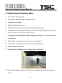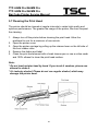
1
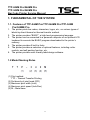
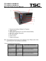
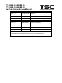
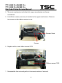
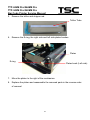
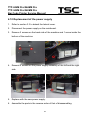
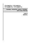
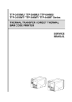
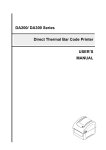
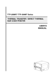
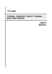
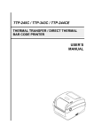
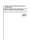
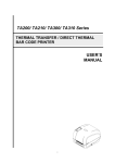
TTP-244M Pro/244ME Pro TTP-342M Pro/342ME Pro THERMAL TRANSFER / DIRECT THERMAL BAR CODE PRINTER SERVICE MANUAL TTP-244M Pro/244ME Pro TTP-342M Pro/342ME Pro Bar Code Printer Service Manual TABLE OF CONTENT 1. FUNDAMENTAL OF THE SYSTEM ........................................................................... 3 1.1. Features of TTP-244M Pro/TTP-244ME Pro/TTP-342M Pro/342ME Pro ............. 3 1.2 Model Naming Rules ...................................................................................... 3 1.3 Overview ......................................................................................................... 4 1.4 Basic Specifications....................................................................................... 7 1.4-2 Electronics/Communication Specifications ................................................ 8 1.5 1.6 Available Bar Codes ...................................................................................... 9 Various Sensors and Switches ................................................................... 10 2. SUPPLY SPECIFICATIONS..................................................................................... 12 2.1 2.2 2.3 Types of Paper .............................................................................................. 12 Paper Specifications .................................................................................... 12 Ribbon Sizes and Shapes ........................................................................... 13 3. ELECTRONICS........................................................................................................ 15 3.1 3.2 Summary of Board Connectors .................................................................. 15 Interface Pin Configuration ......................................................................... 18 3.3 3.4 3.5 3.6 Replacement of Main Board ........................................................................ 20 Print Density Selection ................................................................................ 22 Replacement of the LCD Display ................................................................ 23 Replacement of the Keypad Board ............................................................. 24 4. MECHANISM............................................................................................................ 25 4.1 4.2 4.3 4.3-1 4.3-2 Cutter Installation (Option) .......................................................................... 25 The peel-off module sensor installation (Option) ...................................... 28 Replacement of Printhead ........................................................................... 30 Replacement of Printhead (For ROHM) ...................................................... 30 Replacement of Printhead (For KYOCERA ) .............................................. 34 4.4 4.5 4.6 4.7 4.8 4.9 4.10 DC Motor Replacement................................................................................ 37 Replacement of Stepping Motor ................................................................. 39 Installation of Black Mark Sensor ............................................................... 41 Replacement of Ribbon Sensor (Receiver) ................................................ 43 Replacement of Ribbon Sensor / Gap Sensor (Transmitter) .................... 45 Platen Replacement ..................................................................................... 46 Replacement of the power supply .............................................................. 48 i TTP-244M Pro/244ME Pro TTP-342M Pro/342ME Pro Bar Code Printer Service Manual 5. TROUBLESHOOTING ............................................................................................. 49 5.1 5.2 5.3 5.4 5.5 5.6 5.7 Error Messages ............................................................................................ 49 Troubleshooting ........................................................................................... 51 Calibrating the Gap Register ....................................................................... 53 Self Test ........................................................................................................ 53 Clearing RAM ............................................................................................... 53 Diagnosis Operation Procedure ................................................................. 53 Cleaning the Print Head............................................................................... 54 UPDATE HISTORY ...................................................................................................... 55 ii TTP-244M Pro/244ME Pro TTP-342M Pro/342ME Pro Bar Code Printer Service Manual 1. FUNDAMENTAL OF THE SYSTEM 1.1. Features of TTP-244M Pro/TTP-244ME Pro/TTP-342M Pro/342ME Pro 1. The printer prints bar codes, characters, logos, etc., on various types of labels by direct thermal or thermal transfer method. 2. The printer provides “BASIC”, a high-level programming language. 3. The printer can be connected to a personal computer or an optional LCD keyboard to execute the BASIC program downloaded to the printer’s memory. 4. The printer provides 5 built-in fonts. 5. The printer provides a selection of optional features, including cutter module, and self-peeling function, etc. 6. The printer provides user-friendly label design software. 1.2 Model Naming Rules (1) Print method: TTP – Thermal Transfer Printing (2) Dot density of print head (DPI) (3) Maximum print width (Inch) (4) Maximum print speed (Inch/Sec) (5) M – Metal case 3 TTP-244M Pro/244ME Pro TTP-342M Pro/342ME Pro Bar Code Printer Service Manual 1.3 Overview Front View 9. 8. 10. 7. 6. 5. 1. 4. 2. 3. 1. 2. 3. 4. 5. 6. 7. 8. 9. 10. Printer cover/ Release handle Label dispense opening Liner opening (Option function) MENU button (Option for E series) PAUSE/ SELECT button FEED/ SET button Error indicator On-line indicator LCD display (Option for E series) Power indicator Rear View 4 TTP-244M Pro/244ME Pro TTP-342M Pro/342ME Pro Bar Code Printer Service Manual 3. 2. 4. 1. 5. 6. 7 1. Centronics interface (Option for E series) 2. USB interface 3. Label insert opening (For use with external labels) 4. RS-232C interface connector 5. SD card socket 6. Power switch 7. Power cord socket Note: The interface picture here is for reference only. Please refer to the specification for the interfaces availability. * Recommended SD card specification. SD card spec SD card capacity Approved SD card manufacturer V1.0, V1.1 128 MB SanDisk, Transcend V1.0, V1.1 256 MB SanDisk, Transcend, Panasonic V1.0, V1.1 512 MB SanDisk, Transcend, Panasonic V1.0, V1.1 1 GB SanDisk, Transcend, Panasonic V2.0 SDHC CLASS 4 4 GB V2.0 SDHC CLASS 6 4 GB SanDisk, Transcend, Panasonic V1.0, V1.1 Transcend, Panasonic microSD 128 MB 5 TTP-244M Pro/244ME Pro TTP-342M Pro/342ME Pro Bar Code Printer Service Manual V1.0, V1.1 microSD 256 MB Transcend, Panasonic V1.0, V1.1 microSD 512 MB Panasonic V1.0, V1.1 microSD 1 GB Transcend, Panasonic V2.0 SDHC CLASS 4 microSD 4 GB Panasonic V2.0 SDHC CLASS 6 microSD 4 GB Transcend V1.0, V1.1 miniSD 128 MB Transcend, Panasonic V1.0, V1.1 miniSD 256 MB Transcend, Panasonic V1.0, V1.1 miniSD 512 MB Transcend, Panasonic V1.0, V1.1 miniSD 1 GB Transcend, Panasonic V2.0 SDHC CLASS 4 miniSD 4 GB Transcend V2.0 SDHC CLASS 6 miniSD 4 GB - The DOS FAT file system is supported for the SD card. - Folders/files stored in the SD card should be in the 8.3 filename format - The miniSD/microSD card to SD card slot adapter is required. 6 TTP-244M Pro/244ME Pro TTP-342M Pro/342ME Pro Bar Code Printer Service Manual 1.4 Basic Specifications Thermal transfer and direct thermal printing High dot density printing (203 dots/inch, 8 dots/mm; 300 dots/inch, 12 dots/mm) Selectable print speeds at 1.5”, 2”, 3” or 4” per second for TTP-244M Pro/TTP-244ME Pro, and 1”, 1.5” or 2” per second for TTP-342M Pro/TTP-342ME Pro Maximum media width: 4.49” (114 mm) Adjustable label edge guide International character sets Print area:TTP-244M Pro/TTP-244ME Pro:4.09”W x 90”L;TTP-342M Pro/TTP-342ME Pro:4.09”W x 40”L User selectable bar code ratios and heights Printing on labels or ticket stock Black mark sensor Label stock and thermal transfer ribbon easy to load Internal label print counter Self test Protocol: Xon/Xoff; DSR/DTR handshaking Downloadable fonts from the Windows label design software 7 TTP-244M Pro/244ME Pro TTP-342M Pro/342ME Pro Bar Code Printer Service Manual 1.4-2 Electronics/Communication Specifications Electrical: CPU: ATMEL AT91SAM9260 32bit Stepping Motor: 24V 7.5 Degrees 4Ω DC Motor: DC 24V Memory: DRAM:8MB Flash Memory: 4MB Voltage: Switching Power, 100/240VAC, 50~60Hz Regulations: KCC, S-Mark, CE, FCC, TUV, UL, CCC, C-TICK, Gost-R, BSMI, PSB Energy Efficiency:Level V (Switching Power Supply Only) Communications Interface: RS-232C (DB-9) Band rate: 2400, 4800, 9600, 19200, 38400, 57600 or 115200 band rate Data bit: 7 or 8 data bits Stop bit: 1 or 2 stop bits Parity: None, Even or Odd Handshaking: XON/XOFF and DSR/DTR 8 TTP-244M Pro/244ME Pro TTP-342M Pro/342ME Pro Bar Code Printer Service Manual 1.5 Available Bar Codes 1D bar code Code 39, Code 39C Code 93 Code 128 UCC Code 128, Subsets A, B, and C Codabar Interleaved 2 of 5 EAN-8, EAN-13, EAN-128 UPC-A, UPC-E EAN and UPC with 2 or 5 digits add-on MSI PLESSEY POSTNET ITF14 Code 11 China Post GS1 DataBar 2D bar code PDF-417 Maxicode Data Matrix QR code Aztec 9 TTP-244M Pro/244ME Pro TTP-342M Pro/342ME Pro Bar Code Printer Service Manual 1.6 Various Sensors and Switches 1. Feed Gap Sensor The feed gap sensor detects the label/ticket gap to locate the position. The sensor is set to detect gaps along the center line of the label/ticket roll width across the length of the media. In case of Label 10 TTP-244M Pro/244ME Pro TTP-342M Pro/342ME Pro Bar Code Printer Service Manual 2. Black Mark Sensor The black mark sensor locates the position of the ticket by emitting infrared rays onto the black mark at the back side of the ticket. The sensor is positioned central to the ticket roll width on the mechanism. In case of Ticket 3. Ribbon End Sensor The sensor detects the end portion of the ribbon. 4. Ribbon Encoder Sensor The encoder is located in the gear box of the DC motor and is used to detect whether the ribbon is broken or abnormally rewound. 5. Label End Sensor The sensor detects the end portion of the label. 6. Thermal Head Position Switch The switch detects whether the thermal head is set in a printable status or not. 7. Peel-Off Sensor (Option) The sensor detects the backing paper of the label. 11 TTP-244M Pro/244ME Pro TTP-342M Pro/342ME Pro Bar Code Printer Service Manual 2. SUPPLY SPECIFICATIONS 2.1 Types of Paper Three types of paper are available: (1) label, (2) ticket, (3) direct thermal paper. Note: Our definition of ticket is “the media with black lines on its backing paper”. Item (1), (2), (3) can be further classified into direct thermal type or thermal transfer type. 2.2 Paper Specifications Specifications Items Paper Width Label / Ticket Max. 114 mm Min. 25.4 mm Print Length (Pitch) 6 ~ 2286 mm (For TTP-244M Pro/TTP-244ME Pro) 6 ~ 1016 mm (For TTP-342M Pro/TTP-342ME Pro) Thickness 0.06 mm~0.25 mm, Max 250 g/m2 Max. Roll Diameter Outer roll dia. 178 mm (1” core) Roll Up Method Print surface wound outside as standard Paper Core ID 25.40.3 mm Max. Print Width 25 mm (1") ~ 104 mm (4.09") Note: (1) The max. paper length above is for standard 8MB memory. (2) The printing length above is based on the assumption that there is not any downloaded file in the printer memory. (3) The quoted width and thickness are said of the label plus the backing paper. (4) Likewise, the approval of a label entails that of its backing paper. (5) In the peel off mode, the minimum pitch is 35 mm. (6) In the cutter mode, it is recommended that the print media be wound outside lest paper jam should result. (7) In the cutter mode, the paper thickness must be less than or equal to 250 m. (8) Paper shape is as shown on next page: 12 TTP-244M Pro/244ME Pro TTP-342M Pro/342ME Pro Bar Code Printer Service Manual 2.3 Ribbon Sizes and Shapes Item Specifications Ribbon shape Spool type Ribbon width Ribbon winding width Max. 110 mm Min. 25.4 mm Max. 110 mm Min. 25.4 mm Leader tape Polyester film, 3355 mm long End tape Polyester film (transparent), 2505 mm long Max. ribbon OD. 67 mm Winding method Ink surface wound outside Note: The Max. length of ribbon depends on its core outside diameter and thickness. This formula below defines the correlation between ribbon roll length and ribbon core diameter: 13 TTP-244M Pro/244ME Pro TTP-342M Pro/342ME Pro Bar Code Printer Service Manual L= (D2 d 2 ) 4t , where L = Ribbon length D = Max. roll diameter d = Ribbon core outside diameter t = Ribbon thickness 14 TTP-244M Pro/244ME Pro TTP-342M Pro/342ME Pro Bar Code Printer Service Manual 3. ELECTRONICS 3.1 Summary of Board Connectors Main board 9 2 10 1 11 13 7 8 3 16 14 5 6 12 15 18 4 17 Connector Description 1 Centronics port connector 2 USB connector 3 RS-232C connector 4 LCD panel connector 5 Multi-interface board connector/ GPIO interface board 6 Micro processor 7 RFID module connector 8 Head open sensor connector 15 TTP-244M Pro/244ME Pro TTP-342M Pro/342ME Pro Bar Code Printer Service Manual Pin Description Voltage Head open detect Head open: High Head close: Low Head open detect Head open: High Head close: Low Pin Description Voltage 1 Gap sensor receiver Power 5V Gap sensor receiver Gap: Low Label: High 3 Gnd 0V 4 Gap sensor emitter power 3.3V 5 Gap sensor emitter 0~3.3V 6 GND 0V Pin Description Voltage 1 Power 3.3V 2 Black mark sensor receiver BM: High No BM: Low 3 GND 0V 1 2 Gap sensor connector 2 9 Black mark sensor connector 10 11 Ribbon sensor connector 16 TTP-244M Pro/244ME Pro TTP-342M Pro/342ME Pro Bar Code Printer Service Manual Pin Description Voltage 1 power 3.3V 2 Ribbon sensor receiver With ribbon: High No ribbon: Low 3 GND 0V 4 NC Cutter/peel-off sensor connector 12 Pin Description Voltage 1 Cutter motor wire A 0~24V 2 Cutter position sensor switch Right position: High Error position: Low 3 Cutter motor wire B 0~24V 4 GND 0V 5 GND 0V 6 Peel sensor No paper: High receiver With paper: Low Logic Power 5V 7 DC motor & Ribbon encoder sensor 13 14 Stepping motor connector 15 SD card slot 16 Key & LED Pin Description Voltage 1 Power 5V 2 Encoder sensor Reflect: Low No reflect: High 3 GND 0V 4 DC motor wire A 0~24V 5 DC motor wire B 0~24V 17 TTP-244M Pro/244ME Pro TTP-342M Pro/342ME Pro Bar Code Printer Service Manual Pin Description Voltage 1 Power 3.3V 2 LED Green1 POWER 3 LED Green2 ON-LINE 4 LED Red ERROR 5 Key 1 MENU 6 KEY 2 PAUSE 7 Key 3 FEED 8 GND 0V 17 Power supply input (24V DC) connector 18 Print head signal connector 3.2 Interface Pin Configuration RS-232C PIN CONFIGURATION 1 +5 V 2 TXD 3 RXD 4 CTS 5 GND 6 RTS 7 N/C 8 RTS 9 N/C USB PIN CONFIGURATION 1 N/C 2 D- 3 D+ 4 GND 18 TTP-244M Pro/244ME Pro TTP-342M Pro/342ME Pro Bar Code Printer Service Manual Centronics Pin SPP Mode Nibble In/Out Function 1 Strobe N/A In A low on this line indicates that there are valid data at the host. When this pin is de-asserted, the +ve clock edge should be used to shift the data into the device. 2-9 Data 0-7 N/A In Data Bus. Single-directional. Out A low on this line indicates that there are valid data at the Device. When this pin is de-asserted, the +ve clock edge should be used to shift the data into the host. 10 Ack N/A 11 Busy N/A Out When in reverse direction, a high indicates data, while a low indicates a command cycle. In forward direction, it functions as PtrBusy. 12 Paper Out / N/A End Out When low, device acknowledges reverse request. 13 Select N/A Out Extensibility flag 14 Ground N/A GND 15 No Defined N/A 16-17 Ground 18 N/A No Defined N/A 19-30 Ground N/A N/A GND Ground N/A GND Ground 31 No Defined N/A N/A 32 Error / Fault N/A Out A low set by the device indicates that the reverse data is available GND Ground 33-35 Ground 36 N/A No Defined N/A N/A 19 TTP-244M Pro/244ME Pro TTP-342M Pro/342ME Pro Bar Code Printer Service Manual 3.3 Replacement of Main Board 1. Disconnect printer power. 2. Disconnect RS-232 cable and power cord. 3. Open the front panel. 4. Open the printer top cover. 5. Unfasten the two screws located at the lower edge of the lateral cover, the three screws fastening the lateral cover from inside the printer. Detach the lateral cover from the printer. 6. Disconnect all connectors on the mainboard. 7. Unfasten the ground wire fixing screw, detach the ground wire. 8. Unfasten the 4 mainboard fixing screw. 20 TTP-244M Pro/244ME Pro TTP-342M Pro/342ME Pro Bar Code Printer Service Manual Screws Screws 9. Replace with the new mainboard. 10. Assemble the parts in the reverse order of that of disassembling. 21 TTP-244M Pro/244ME Pro TTP-342M Pro/342ME Pro Bar Code Printer Service Manual 3.4 Print Density Selection As shown, on the lower edge of the mainboard JP47 is jumper to be used in the selection of print density. To select 200 dpi print density, cap jumper on positions 200DPI, as described in the instructions beside. To select 300 dpi print density, cap jumper on positions 300DPI. 22 TTP-244M Pro/244ME Pro TTP-342M Pro/342ME Pro Bar Code Printer Service Manual 3.5 Replacement of the LCD Display 1. Refer to section 3.3 to detach the lateral cover. 2. Disconnect the connector to the LCD display. 3. Unfasten the 4 fixing screws on the LCD display. 4. Replace with the new LCD display. 5. Assemble the parts in the reverse order of that of disassembling. 23 TTP-244M Pro/244ME Pro TTP-342M Pro/342ME Pro Bar Code Printer Service Manual 3.6 Replacement of the Keypad Board 1. Refer to section 3.3 to detach the lateral cover. 2. Disconnect the connector to the keypad board. 3. Unfasten the 4 fixing screws on the keypad board. 4. Replace with the new keypad board. 5. Assemble the parts in the reverse order of that of disassembling. 24 TTP-244M Pro/244ME Pro TTP-342M Pro/342ME Pro Bar Code Printer Service Manual 4. MECHANISM 4.1 Cutter Installation (Option) 1. Turn off the printer power. 2. Open the top cover. 3. Detach the front panel by loosening four screws. Front Panel 4. Install the cutter mode front panel. 25 TTP-244M Pro/244ME Pro TTP-342M Pro/342ME Pro Bar Code Printer Service Manual Cutter Mode Front Panel 5. Insert cutter module tenons in the cuts on the carriage, slide the cutter module to the right. Cutter Tenons Cuts 6. Fix the cutter module in place with the provided screw, plug in cutter module power. 26 TTP-244M Pro/244ME Pro TTP-342M Pro/342ME Pro Bar Code Printer Service Manual Screw Power Power Cord Connector Cord Clips 7. Refer to section 3.3 to disconnect all connectors on the mainboard. 8. Install the cutter driver IC which is attached to the package of cutter module at U505 on the main board. 9. Assemble the parts in the reverse order of that of disassembling. The hole must be at the left side. 27 TTP-244M Pro/244ME Pro TTP-342M Pro/342ME Pro Bar Code Printer Service Manual 4.2 The peel-off module sensor installation (Option) 1. Turn off the printer power. 2. Open the top cover. 3. Disconnect the gap sensor power connector below the carriage, detach the front panel. 4. Loosen the screws on the front panel and take it off. The peel-off sensor launcher and receiver Peel-off sensor assembly 28 TTP-244M Pro/244ME Pro TTP-342M Pro/342ME Pro Bar Code Printer Service Manual 5. Put the peel-off sensor assembly in the peel-off sensor housing and the peel-off sensor receiver must be at the downside. 6. Assemble the detached parts in reverse order of the steps above. 7. Connect the peel-off sensor assembly power connector to the connector jack. Peel-off sensor assembly power connector 29 TTP-244M Pro/244ME Pro TTP-342M Pro/342ME Pro Bar Code Printer Service Manual 4.3 Replacement of Printhead 4.3-1 Replacement of Printhead (For ROHM) For 203 dpi 1. Turn off the printer power. Open the top cover and front panel. 2. Dismantle label and ribbon. 3. Loosen 4 screws on the ribbon base assembly to move it. 4. Loosen 2 screws (black) as photo shown. 30 TTP-244M Pro/244ME Pro TTP-342M Pro/342ME Pro Bar Code Printer Service Manual 5. Disengage printhead carriage. 6. Take out the printhead module. 7. Remove 2 screws on printhead module. 31 TTP-244M Pro/244ME Pro TTP-342M Pro/342ME Pro Bar Code Printer Service Manual 8. Disconnect printhead cables, replace with the new printhead. 9. Tidy the cable so as not to interfere with the ribbon. 10. Assemble the detached parts in reverse order of the steps above. Note: Connector lock is to face up Do not touch printhead elements Do not tear printhead apart 32 TTP-244M Pro/244ME Pro TTP-342M Pro/342ME Pro Bar Code Printer Service Manual For 300 dpi 1. Turn off the printer power. Open the top cover and front panel. 2. Dismantle label and ribbon. 3. Disengage printhead carriage. 4. Loosen 1 screw in the front center of the printer head. 5. Disconnect printhead cable, replace with the new printhead. 6. Tidy the cable so as not to interfere with the ribbon. 7. Assemble the detached parts in reverse order of the steps above. Note: Connector lock is to face up Do not touch printhead elements Do not tear printhead apart 33 TTP-244M Pro/244ME Pro TTP-342M Pro/342ME Pro Bar Code Printer Service Manual 4.3-2 Replacement of Printhead (For KYOCERA) 1. Turn off the printer power. Open the top cover and front panel. 2. Dismantle label and ribbon. 3. Loosen 4 screws on the ribbon base assembly to move it. 4. Loosen 2 screws (black) as photo shown. 5. Disengage printhead carriage. 34 TTP-244M Pro/244ME Pro TTP-342M Pro/342ME Pro Bar Code Printer Service Manual 6. Take out the printhead module. 7. Remove the e-ring at the mechanism. E-ring 35 TTP-244M Pro/244ME Pro TTP-342M Pro/342ME Pro Bar Code Printer Service Manual 8. Remove 2 screws on printhead module. Screws 9. Disconnect printhead cable, replace with the new printhead module. 10. Reassemble the removed parts in the reverse order of removal. Note: 1. Tidy up the cable so that it does not protrude or interfere with the ribbon. 2. Do not touch the elements of the print head. 3. Do not disassemble the print head. 36 TTP-244M Pro/244ME Pro TTP-342M Pro/342ME Pro Bar Code Printer Service Manual 4.4 DC Motor Replacement 1. Turn off the printer power. 2. Disconnect RS-232 cable and power cord. 3. Open the front panel. 4. Open the top cover. 5. Detach the lateral cover by loosening its 5 fixing screws. 6. Unfasten the 4 mechanism fixing screws on the carriage: one in upper-right, lower left corner each, two in the lower right corner. 2 1 4 3 7. Disengage the mechanism, push the mechanism forward for about 1 cm, take out the mechanism. 8. Loosen the screw in the center of the DC motor cover. i. 37 TTP-244M Pro/244ME Pro TTP-342M Pro/342ME Pro Bar Code Printer Service Manual 9. Detach the ground wire on the mainboard. 10. Disconnect all mechanism connectors from mainboard. 11. Take out the mechanism. 12. Cut off the cable tie. Unfasten the 3 screws on the fixing tab of DC motor. 13. Replace with the new DC motor and connection wires. Note: The colors of DC motor connection wires are, from left to right, yellow, green, orange, red, gray. 14. Assemble the detached parts in the reverse order of the steps above. 38 TTP-244M Pro/244ME Pro TTP-342M Pro/342ME Pro Bar Code Printer Service Manual 4.5 Replacement of Stepping Motor 1. Turn off the printer power. 2. Disconnect RS-232 cable and power cord. 3. Open the front panel. 4. Open the printer top cover. 5. Detach the lateral cover by loosening its 5 fixing screws. 6. Unfasten the 4 mechanism fixing screws: one in upper-right and lower-left corner each, two in the lower-right corner. 7. Disengage the mechanism, slide mechanism forward for 1 cm, take out the mechanism. 8. Detach the mechanism's ground wire on mainboard. 9. Disconnect all mechanism connectors from mainboard. 10. Take out the mechanism. 11. Unfasten the 2 stepping motor fixing screws, as shown. 12. Cut off the cable tie, replace with the new stepping motor and connection wires. 39 TTP-244M Pro/244ME Pro TTP-342M Pro/342ME Pro Bar Code Printer Service Manual 13. Assemble the detached parts in the reverse order of the above steps. 40 TTP-244M Pro/244ME Pro TTP-342M Pro/342ME Pro Bar Code Printer Service Manual 4.6 Installation of Black Mark Sensor 1. Turn off the printer power. 2. Disconnect RS-232 cable and power cord. 3. Open the front panel. 4. Open the top cover. 5. Detach the lateral cover by unfastening its 5 fixing screws. 6. Loosen the 4 mechanism fixing screws. 7. Disengage the ribbon mechanism, slide mechanism forward for 1 cm, take out the mechanism. 8. Detach the mechanism ground wire on the mainboard. 9. Disconnect all mechanism connectors from mainboard. 10. Take out the mechanism and stand the mechanism perpendicularly as shown. 11. Remove two screws and black mark sensor PCB. 12. Replace with the new black mark sensor and connect in wires, fix the connection wires in the guide slots as shown. Black mark sensor PCB 41 TTP-244M Pro/244ME Pro TTP-342M Pro/342ME Pro Bar Code Printer Service Manual 13. Assemble the detached parts in the reverse order of the steps above. Note: Black mark sensor connector is to be connected to J601 42 TTP-244M Pro/244ME Pro TTP-342M Pro/342ME Pro Bar Code Printer Service Manual 4.7 Replacement of Ribbon Sensor (Receiver) 1. Follow the instructions in Section 4.3 to take out the mechanism. 2. Open the print top cover. 3. Remove the screws, springs and spring bushing on both sides of the mechanism. Spring bushing Screws Spring Note: The left side spring and the right side spring are different in shape. The right side spring has a straight end, when the left side spring has an end that is curved 90 degrees. 43 TTP-244M Pro/244ME Pro TTP-342M Pro/342ME Pro Bar Code Printer Service Manual 4. The main mechanism is divided into upper mechanism and lower mechanism. 5. And ribbon sensor (receiver) is located in the upper mechanism. Remove the screws on the ribbon sensor cover. Sensor Cover Screws 6. Replace with a new ribbon sensor PCB. Ribbon sensor PCB 7. Reassemble the removed parts in the reverse order of removal. 44 TTP-244M Pro/244ME Pro TTP-342M Pro/342ME Pro Bar Code Printer Service Manual 4.8 Replacement of Ribbon Sensor / Gap Sensor (Transmitter) 1. Please follow the steps in Section 4.6 to separate the upper mechanism from the lower mechanism. 2. The ribbon sensor (transmitter) is located in the center of the lower mechanism. Ribbon sensor (transmitter) PCB 3. Remove the two screws. Screws 4. Remove the cable tie and sensor PCB. 5. Replace with a new PCB. Reassemble the removed parts in the reverse order of removal. 45 TTP-244M Pro/244ME Pro TTP-342M Pro/342ME Pro Bar Code Printer Service Manual 4.9 Platen Replacement 1. Follow the instructions in Section 4.4 to remove the stepping motor. 2. Loosen the E-ring 1 to remove the 2 gears. 3. Lossen the E-ring 2 to remove the release lever arm. Printhead Release lever arm E-ring 1 Gear 1 E-ring 2 Gear 2 4. Remove the E-ring and the mechanism release lever on the left side of the mechanism. Printhead Bracket Mechanism Release Lever E-ring 46 TTP-244M Pro/244ME Pro TTP-342M Pro/342ME Pro Bar Code Printer Service Manual 5. Remove the teflon and stripper rod. Teflon Tube 6. Remove the E-ring, the right side and left side platen bushes. Platen E-ring Platen bush (Left side) 7. Move the platen to the right of the mechanism. 8. Replace the platen and reassemble the removed parts in the reverse order of removal. 47 TTP-244M Pro/244ME Pro TTP-342M Pro/342ME Pro Bar Code Printer Service Manual 4.10 Replacement of the power supply 1. Refer to section 3.3 to detach the lateral cover. 2. Disconnect the power supply on the mainboard. 3. Remove 2 screws on the back side of the machine and 1 screw inside the bottom of the machine. 4. Remove 4 screws on the power supply assembly of the left and the right side. 5. Replace with the new power supply. 6. Assemble the parts in the reverse order of that of disassembling. 48 TTP-244M Pro/244ME Pro TTP-342M Pro/342ME Pro Bar Code Printer Service Manual 5. TROUBLESHOOTING 5.1 Error Messages 1. Syntax Error The command format is incorrect. The serial port setting is incorrect. 2. Out of Range Numeric input is too large to be processed. The input string is too long to be stored. The size of the text or bar code exceeds that of the label. 3. Download Error The download file format is incorrect. There is not enough memory to store the file. 4. Stack Overflow A mathematical expression is too complicated. Divide it into several expressions. The nested routine is too deep. 5. Memory Error Too many variables defined. 6. RS-232 Error The serial port setting is incorrect. 7. File not Found Cannot open the file specified. Download the file again. 8. Type Mismatch Variable type mismatch. 49 TTP-244M Pro/244ME Pro TTP-342M Pro/342ME Pro Bar Code Printer Service Manual 9. Gap not Found Cannot detect label gap. Calibrate the label again. 10 Clock Access Error Can not read from / write to the real time clock. 50 TTP-244M Pro/244ME Pro TTP-342M Pro/342ME Pro Bar Code Printer Service Manual 5.2 Troubleshooting The following guide lists some of the most common problems that may be encountered when operating the bar code printer. If the printer still does not function after all suggested solutions have been invoked, please contact the Customer Service Department of your purchased reseller or distributor for assistance. Problem Solution Ribbon does not advance or rewind Check the setting of print method. (SET RIBBON ON) Poor print quality Clean the thermal print head. Adjust the print density setting. Ribbon and media are not compatible. Power indicator does not illuminate Check the power cord, see whether it is properly connected. ON-LINE indicator is off Out of paper or out of ribbon Calibrate the sensitivity of gap sensor. ERROR indicator lights on Command syntax is not correct. Rewind ribbon paper core is not installed. Serial port baud rate setting is not correct. Continuous feeding when printing labels Calibrate the gap sensor. 51 TTP-244M Pro/244ME Pro TTP-342M Pro/342ME Pro Bar Code Printer Service Manual Note: When the voltage is too low or when the printing covers a wide range on the label, the print density may become inadequate. At this, please lower the print speed to secure normal print quality. 52 TTP-244M Pro/244ME Pro TTP-342M Pro/342ME Pro Bar Code Printer Service Manual 5.3 Calibrating the Gap Register 1. Install the label. 2. Turn on the printer power while pressing the PAUSE button, the printer will calibrate the transparency of the backing paper and adjust the gap register. 5.4 Self Test 1. Install the label. 2. Turn on the printer power while pressing the FEED button, the printer will: (1) Print print head check pattern. (2) Calibrate the label length. (3) Print internal settings. (4) Initiate self-test. (5) Enter dump mode. 5.5 Clearing RAM Press the PAUSE button and FEED button more than 3 seconds, the printer will clear the memory and reset the printer. Be sure to calibrate the gap register with blank label before printing. 5.6 Diagnosis Operation Procedure When the power is turned on without pressing any button, self diagnosis is automatically performed to test the available memory. If any error should occur at this moment, the ERR light will flash. Do the self test and inspect the test pattern to check if the thermal head is available. 53 TTP-244M Pro/244ME Pro TTP-342M Pro/342ME Pro Bar Code Printer Service Manual 5.7 Cleaning the Print Head The printer should be cleaned at regular intervals to retain high quality and optimum performance. The greater the usage of the printer, the more frequent the cleaning. 1. Always turn off the printer before cleaning the print head. Allow the printhead to cool for a minimum of one minute. 2. Open the printer cover. 3. Open the printer carriage by pulling up the release lever on the left side of the front rubber roller. 4. Remove the ribbon and label. 5. Clean the print had element with a head cleaner pen or use a cotton swab and 100% ethanol to clean the print head surface. Note: * Do not touch printer head by hand. If you touch it careless, please use ethanol to clean it. * It’s industry alcohol. Please do not use regular alcohol, which may damage the printer head. 54 TTP-244M Pro/244ME Pro TTP-342M Pro/342ME Pro Bar Code Printer Service Manual UPDATE HISTORY Date 2015/5/28 Content Modify section 4.3 Editor Camille 55 Corporate Headquarters 9F., No.95, Minquan Rd., Xindian Dist., New Taipei City 23141, Taiwan (R.O.C.) TEL: +886-2-2218-6789 FAX: +886-2-2218-5678 Web site: www.tscprinters.com TSC Auto ID Technology Co., Ltd. E-mail: [email protected] [email protected] 57 Li Ze Plant No.35, Sec. 2, Ligong 1st Rd., Wujie Township, Yilan County 26841, Taiwan (R.O.C.) TEL: +886-3-990-6677 FAX: +886-3-990-5577