1
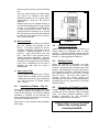
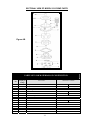
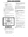
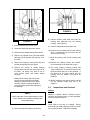
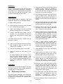
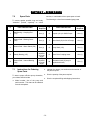
E AGL E
Installation, Operation and
Maintenance Instructions
EAGLE MODEL
S300 & S310
SUMP PUMPS
Revised: 10/2003
-1-
TABLE OF CONTENTS
INTRODUCTION
...…………………………………………………….
1
……………………………………………………………
……………………………………………………………
……………………………………………………………
……………………………………………………………
……………………………………………………………
1
1
2
2
2
……………………………………………………………
……………………………………………………………
……………………………………………………………
……………………………………………………………
……………………………………………………………
……………………………………………………………
……………………………………………………………
……………………………………………………………
……………………………………………………………
2
2
2
3
3
3
3
4
4
……………………………………………………………
……………………………………………………………
……………………………………………………………
……………………………………………………………
……………………………………………………………
……………………………………………………………
……………………………………………………………
……………………………………………………………
……………………………………………………………
4
4
4
4
4
5
5
5
5
……………………………………………………………
……………………………………………………………
……………………………………………………………
……………………………………………………………
6
7
8
8
……………………………………………………………
……………………………………………………………
……………………………………………………………
……………………………………………………………
……………………………………………………………
……………………………………………………………
9
9
9
10
11
13
……………………………………………………………
15
……………………………………………………………
……………………………………………………………
……………………………………………………………
16
16
17
SECTION 1 - Safety Regulations
Safety Regulations
Importance of Instructions
Receiving Inspection -Shortages
Preservation & Storage
Handling Techniques
SECTION 2 –Installation
Preparation for Installation
Installation of Unit in Pit
Stuffing Boxes
Installation of Motor
Impeller Adjustments
Rotation Check
Connection of Flexible Coupling
Piping
Level Controls
SECTION 3
- Operation
Bearings
Motor Bearing & Coupling
Priming
Flush Flows
Check for Free Turning
Operating at Reduced Flows
Operating at Reduced Heads
Operating with Surge Conditions
Freezing Conditions
SECTION 4 – Product Information
Sectional View
Parts List & Materials of Construction
Sectional View of Model S310
Parts List and Materials of Construction
SECTION 5 – Care & Maintenance
Lubrication
Adjusting Impeller Clearance
Disassembly Procedures
Inspections & Overhauls
Reassembly Procedures
Rotary Vapour Seal
SECTION 6 – Trouble Shooting
Trouble Shooting
SECTION 7 – Spare Parts
Spare Parts
Instructions for Ordering Spare Parts
Eagle Warranty
INTRODUCTION
This instruction manual is intended to
assist those involved with the installation,
operation, and maintenance of Eagle Model
S300 Series Pumps. It is recommended
that this manual be thoroughly reviewed
prior to installing or performing any work
on the pump or motor.
!
!
WARNING
Read this manual and
follow the safety directions
before installing or
operating this unit.
WARNING
Eagle Pump & Compressor Ltd. will not be liable for any
damages or delay caused by failure to comply with the
provisions of this instruction manual. This pump is not
to be operated at speeds, working pressures, discharge
pressures or temperatures higher than, nor used with
liquids other than originally intended for, without
written permission from Eagle Pump & Compressor Ltd.
SECTION 1 - SAFETY REGULATIONS
1.0
Safety Regulations
1.1
In addition to the general technical
regulations of the local authorities, the
following guidelines must be strictly
observed:
The design, material and workmanship
incorporated in the construction of Eagle
pumps makes them capable of giving long,
trouble-free service. The life and satisfactory
service of any mechanical unit, however; is
enhanced and extended by periodic
inspection and careful maintenance. This
instruction manual was prepared to assist
operators in understanding the construction
and correct methods of installing, operating
and maintaining these pumps.
Failure to observe these notices
could result in severe personal
injury, death, property damage
and/or pump damage.
♦
Importance of Instructions
Study thoroughly Sections 1, 2 & 3 and carefully
follow the instructions for installation and
operation. Sections 4, 5, 6 & 7 are answers to
trouble and maintenance questions. Keep this
instruction manual handy for reference.
The pump should only be operated within
the rated conditions of the pump. Do not
operate the pump at other than intended
speeds, working pressures, discharge
pressures, temperatures and oil levels
without written permission from Eagle
Pump & Compressor Ltd.
-1-
1.2
Receiving Inspection –
Shortages
Care should be taken when unloading pumps. If
the shipment is not delivered in good order and
in accordance with the Bill-of-Lading, note the
damage or shortage on both the receipt and
freight bill.
MAKE ANY CLAIMS TO THE
TRANSPORATION COMPANY
PROMPTLY.
The driver, coupling, and seal manufacturers
should be contacted for their recommendations on
preservations and protection procedures.
Instruction sheets on various components as
well as the Instruction Book and “Shipped
Loose” for the pump are included in the
shipment. DO NOT DISCARD!
.
1.3
Preservation and Storage
Eagle’s normal domestic storage preparation is
suitable for protecting the pump during shipment
in covered trucks. It also provides protection
.
2.0
Location
Preparation for Installation
Vertical
units
are
shipped
completely
assembled, except level controls, coupling
inserts and suction screen (S300-A only).
Check all bolts and nuts on entire unit to make
sure they are securely tightened. Install level
controls and suction screen per manufacturer’s
recommendations.
2.1
♦
♦
1.4
Handling Techniques
Care should be used in moving pumps. Pumps
should not be hoisted by the motor eyebolts, or
discharge pipe. Eyebolts, if installed, are intended
for removing the electric motor. Discharge piping
cannot support the full or partial weight of the
pump and may break. An assembled pump
should be hoisted using a sling through the lifting
lugs provided.
SECTION 2 - INSTALLATION
Pump unit should be placed as close as
practical to the source of supply. Floor space
and headroom allotted to the unit must be
sufficient for inspection and maintenance. Be
sure to allow for crane or hoist service.
2.0
during covered storage at the jobsite, and for the
short period between installation and start-up. If
the pump is to be idle and exposed to the
elements for an extended period, either before or
after installation, special precautions are required.
One approach is to provide special preservatives
and wrapping before shipment. However, after
installation, the protective wrappings will have
been removed.
Therefore, application of
preservatives after installation is considered a
good practice.
Installation of Unit in Pit
Installation must be done with care to avoid
damage and to ensure proper operation.
Check clearance between the unit and pit.
There must be at least ½” clearance
between the sides of the pumping unit and
any portion of the pit.
-2-
♦
There should be 4 to 6” from the bottom of the
pump to the bottom of the pit.
♦
Lower assembled pump carefully into pit.
Guide unit carefully so that it does not strike
the sides of the pit.
♦
When the coverplate is supported on the pit,
level the coverplate. Shim under coverplate
when necessary to level the unit. Pump must
hang straight down to avoid placing a bending
stress on the unit. Bolt coverplate to the
supports on the pit.
2.2
Stuffing Boxes
An upper stuffing box is available as an option
when it is desirable to seal vapors, fumes, etc., in
the sump or tank.
A) Packing – Upper Stuffing Box
Packing rings are supplied and special care
must be used during installation. To pack the
stuffing box, install the packing and lantern
ring in the proper sequences, 3 rings, lantern
ring, 2 rings, and gland. Firmly seat each ring.
Stagger joint in each 90°. Make sure center of
lantern ring lines up flush, tap in the stuffing
box.
Since the upper stuffing box seals vapors
only, there is no leakage at the gland.
Standard lubrication is by a grease fitting.
Approximately 5 shots per 100 hours is
adequate.
Sealing liquid may be supplied through a
line from the discharge pipe if the pump fluid
is clean. If it is abrasive, an outside source
of clean liquid should be used. After the
packing has been completely run in, at least
40 to 60 drops per minute should be allowed
to trickle from the stuffing box at all times
with a clean liquid flush.
FIGURE 1.
B) Mechanical Seals
When the mechanical seals are furnished,
they are installed and adjusted at the
factory. To properly prepare the seal for
operation, lubrication or flush lines must be
connected. Standard lubrication is an oil
reservoir – gravity fed directly to the seal
face. Seal flush is also provided and is
shipped completely assembled. Separate
seal manufacturer’s installation drawings are
attached to the pump and should be filed for
future use in maintaining the seal and in
adjusting the seal when the pump is
disassembled.
C) Rotary Vapour Seal
If your pump is equipped with a Rotary
Vapour Seal, the constant level oil must be
installed and the resevoir must be filled with
oil. Refer to Section 5.5 “Rotary Vapour
Seal – Step #7”
2.3
Installation of Motor – Fig. 1.0
2.4
Impeller Adjustment
Impeller clearance is adjusted at the factory, but
should always be re-adjusted prior to pump
operation. Clearance between impeller and the
casing should be checked using the procedure in
Section 5.1, Adjusting Impeller Clearance.
2.5
Rotation Check
Before the coupling is connected, the motor
should be wired and the direction of rotation
checked. A rotation arrow is located on the motor
support. Serious damage can result if the pump is
run in the wrong direction. Standard rotation for
the S300/S310 Series Pump is CW as viewed
from the driver. Once the motor rotation is
checked, connect the coupling, following the
manufacturer’s instructions. If a coupling guard is
furnished with the unit, ensure that it is securely
fastened in place.
2.6
Connection of Flexible Coupling
If the motor is shipped from Eagle’s shop, both
the coupling halves will be assembled on shafts
in their correct positions. If the motor is shipped
separately or furnished by the customer, the
motor coupling half must be fitted on the motor
shaft prior to installing the motor.
Connect coupling; follow the instructions in the
provided box for the particular make of coupling
used. This data is supplied separately, giving
complete instructions for the connection,
lubrication, alignment and maintenance.
Place motor on motor support (240) and tighten
bolts snugly.
Pump should never be operated
without the coupling guard
correctly installed.
-3-
2.7
B) Metallic Bearings
Piping
Guidelines for piping are given in the “Hydraulic
Institute Standards” and should be reviewed
prior to pump installation. All piping should be
supported independently of, and line up naturally
with, the pump flanges.
Both cast iron and bronze steady bearings are
available and must be grease lubricated. Lack
of lubrication can lead to galling and eventual
seizing. It becomes extremely difficult to keep
enough grease in the housing when handling
hot liquids, caustic solutions or solvents.
NEVER DRAW PIPING INTO PLACE BY USE
OF
FORCE
AT
THE
FLANGED
CONNECTIONS OF THE PUMP.
Discharge piping should be short and as direct
as possible to minimize friction losses.
Foundation, pump and driver hold-down bolts
should be tightened prior to connecting
discharge piping to the pump.
2.8
Unless an adequate maintenance program
exists, it is recommended that a selflubricating bearing such as a carbon be used
in place of the metallic bearing.
C) Lubrication
The type of grease to be used is Shell Alvania
E.P.I. Lowtherm or equal.
Level Controls
Consult the manufacturer’s recommendation
regarding the installation, maintenance and
operation of float switches and/or level controls.
!
WARNING
Improper installation and/or
operation could cause the pump
to run dry, resulting in serious
damage to your pump.
SECTION 3 - OPERATION
3.0
Bearings
3.1
Motor Bearing and Coupling
Thrust Bearing
Ball bearings are standard on all S300 Series
Pumps and are lubricated at the factory. Do not
grease at too frequent intervals. Approximately
10 shots every 100 hours is adequate. The type
of grease to be used is Shell Alvania E.P.I. or
equal.
Steady Bearings
A) Carbon Bearings
These bearings are chemically inert in most
liquids and can be used in liquids up to the
temperature limits of the pump.
The carbon bearing is sealed within the
housing by two lip seals and filled with
grease by a pressure lubricator located
above the support plate. The pressure cup
must be kept full of grease.
-4-
Check to be sure the motor bearings and coupling
are properly lubricated.
Refer to the
manufacturers recommendations.
3.2
Priming
Before starting up the pump, check the impeller
centerline submergence. The pump must be full
of liquid with specified submergence head above
the centerline of the impeller.
DO NOT run the pump dry, as this might damage
the pump parts or steady bearings.
3.3
Flush Flows
Before the pump is started, the flushing flow
should be started (when furnished).
3.4
Check for Free Turning
Before the pump is started, rotate the pump by
hand to make sure it turns freely, and does not rub
or bind.
Packing and/or mechanical seal, if
supplied, could interfere with free turning.
3.5
Operating at Reduced Flows
3.8
A centrifugal pump should never be operated
continuously near shut-off or zero capacity, or
with the discharge valve closed. To do so may
shorten the life of the pump and greatly increase
down time and maintenance.
Operation with the discharge valve closed will
cause a temperature increase in the liquid within
the casing. If this condition exists over a long
period, the temperature of the liquid may
increase until the boiling point is reached. If this
occurs, the rotating parts are exposed to vapor
and may score or seize to stationary parts.
Hydraulic radial thrust is unbalanced when the
pump is operating near shut-off and this subjects
the shaft to abnormal deflection and accelerated
lower steady bearing wear. The pump will be
noisy, will vibrate excessively and may result in
shaft breakage.
A simple method of relieving the pump of undue
strain is to extend a by-pass line from the pump
discharge line back to the sump or tank. A
throttle valve or an orifice plate should be placed
by the bypass line and sufficient flow returned to
allow the pump to operate at a capacity
reasonably near its rating. The by-passed liquid
should always be returned to the source of
supply and discharged below the liquid level to
avoid air entrapment.
3.6
Operating at Reduced Heads
When the discharge head or pressure is
dropped considerably below the rated point for
any length of time, the motor should be watched
for overloading. If this condition is likely to
persist, arrangements should be made either to
manually or automatically throttle the discharge
valve to build up head to a safe point.
3.7
Operating with Surge
Conditions
If the pump is installed with a quick closing valve
in the discharge line that closed when the pump
is running, dangerous pressure surges may be
built up that can cause damage to the pump or
line. In services of this kind, some cushioning
arrangement must be provided to protect the
pumping equipment.
-5-
Freezing Conditions
When exposed to freezing conditions and the
pump is standing idle, special precautions should
be taken to prevent freezing and pump damage.
Flush lines should also be properly protected form
freezing.
SECTION 4 – PRODUCT DESCRIPTION
Figure 4.A.
SECTIONAL VIEW
-6-
PARTS LIST AND MATERIALS OF CONSTRUCTION
Item
No.
100
101
102
105
106
107
111
112
113
122
134
136
178
182
187
189
190
191
192
193
194
195
197
198
199
213
221
240
306
315
332
333
334
351
361
370-A
370-B
370-C
No.
Req’d
Per
Pump
1
1
1
1
1 Set
1
1
1
1
1
1
1
1
1
1
1
▲
▲
1
1
▲
1
▲
1
1
▲
1
1
▲
1
1
1
▲
1
1
6
4
3
370-D
370-E
370-G
371-H
370-J
371
3
▲
6
6
4
1
Standard Material of Construction 1
Part Name
Casing ●
Impeller ●
Adapter Plate – Column to Casing
Upper Stuffing Box Lantern Ring*
Upper Stuffing Box Packing*
Upper Stuffing Box Gland*
Bearing Housing Cover
Ball Bearing
Dust Cover
Pump Shaft
Bearing Housing
Retainer Nut – Ball Bearing
Impeller Key ●
Suction Cover ●
Strainer ●
Mounting Plate
Lubrication or Flush Line*
Flush Line Elbow*
Head Column
Grease Fitting – To Bearing Housing
Grease Fitting – To Intermediate Bearings
Discharge Pipe
Steady Bearing
Impeller Screw ●
Impeller Washer ●
Intermediate Bearing Housing
Stuffing Box*
Motor Support
Column Extension
Discharge Elbow
Grease Seal – Bearing Cover
Grease Seal – Motor Stand
Grease Seal – Intermediate Bearing
Gasket – Suction Cover to Casing ●
Retainer Washer – Ball Bearing
Capscrew Column to Motor Stand
Capscrew Motor Stand to Support Plate
Capscrew – Bearing Housing Cover to Bearing
Housing
Capscrew – Adjustable
Capscrew with Nut-Column to Intermediate Bearing
Capscrew with Nut-Column Pipe to Casing ●
Capscrew – Strainer to Casing ●
Capscrew with Nut – Discharge Elbow to Casing ●
Gasket – Stuffing Box to Mounting Plate*
316SS
Fitted
All Iron
All
316SS
C.I.
C.I.
C.I.
316
C.I.
316 – Teflon
Teflon
C.I. or as Specified
C.I.
Steel
C.I.
Steel
C.I.
Steel
316
C.I.
C.I.
Steel or as Specified
Steel
Steel
Steel
Steel
Steel
Steel
Carbon ■
Alloy Plated Steel
416
C.I>
C.I. or as Specified
C.I.
Steel
Steel
Nitrile
Nitrile
Nitrile/Viton/Aflas
Non Asbestos
Steel
Steel
Steel
416
316
316
316
316
304
316
316
316
316
316
316
316
Steel
Steel
Steel
Steel
Steel
Steel
Neoprene
●
Please refer to Figure 4-B for S310 pumps.
▲
■
*
Quantity dependent on pit depth.
Also available in Teflon, bronze and iron. Use 316 or alloy shaft with rubber or viton bearings.
Optional equipment.
-7-
316
316
316
316
316
316
316
SECTIONAL VIEW OF MODEL S310 PUMP PARTS
Figure 4.B.
PARTS LIST AND MATERIALS OF CONSTRUCTION
No.
Req’d per
Pump
CPL
1
AD-10
1
20
1
21
2
22
1
23
1
24
1
25
2
26
1
27
1
30
6
31
2
32
8
33
1
34
1
35
1
Item
No.
Part Name
Coupler
Adapter Plate
Casing
Pipe Plug
Rotor and Shaft
Idler
Idler Bushing
Head Gasket
Idler Pin
Head
Cap Screw for Head
Relief Valve Gasket
Cap Screw for Valve
Internal Relief Valve
Suction Elbow
Suction Filter
Material Available
Steel
Steel
Iron
S.S.
S.S.
Steel
Steel
Iron/Steel
Steel/Steel
Iron
Steel
Carbon Graphite
Standard
Hard Steel
Iron
Steel
Steel
Standard
Steel
Iron
Steel
Steel
Iron
-8-
SECTION 5 – CARE & MAINTENANCE
5.0
e) Make sure jam nuts on bolts (D) are loose.
Tighten bolts (D) evenly until bearing shell is
tight against bolts (C). Make sure all bolts
are tight. Tighten jam nuts.
Lubrication
1) Thrust Bearing. See Section 3 –
Bearings
2) Steady Bearing. See Section 3 –
Bearings.
3) Motor Bearing and Coupling. Follow
manufacturer’s recommendation
5.1
f)
Adjusting Impeller Clearance
If a gradual loss in head and/or capacity occurs,
performance can be restored by adjusting the
impeller.
It is also recommended that the
impeller clearance be set at installation prior to
start up.
To adjust the impeller clearance:
a) Disconnect Coupling
b) Loosen adjustment bolts and jam nuts (D) in
Figure 2.
c) Tighten shell bolts (C) in Figure 2., while
rotating the shaft until the impeller lightly
contacts the suction cover.
Connect coupling.
With the above method, the rotating element and
impeller have been moved the desired distance
away from the suction cover, thus giving the
required clearance between these two parts.
Rotate shaft several times to check for free
turning.
5.2
Disassembly Procedures
TO PREPARE FOR DISASSEMBLY PROCEED
AS FOLLOWS:
a) Never use heat to disassemble the pump;
this could cause an explosion by any
trapped liquid.
b) Lock out power supply to motor.
c) Shut off valves controlling the flow from the
pump.
d) Disconnect coupling.
e) Disconnect motor and remove the motor from
the support.
f)
Disconnect the discharge
discharge flange.
pipe
at
the
g) Dismantle the flow controls (when furnished).
h) Remove the bolts holding mounting plate to
support and lift the pump from the sump and
lay horizontally on the proper supports.
i)
FIGURE 2.
d) Loosen bolts (C) until the following
clearances are reached between the
underside of the bolt head and the bearing
shell.
-
S300 pumps – 0.015” plus 0.004” per
intermediate bearing and packing.
-
S310 pumps – 0.005” plus 0.004” per
intermediate bearing and packing.
-9-
Remove the stuffing box gland if any
corrosive and/or toxic fluids are pumped.
USE EXTREME CAUTION!
The numbers located on Figure 3, refer to the
procedure steps. e.g.: Number 1. Refers to
Step 1.
FIGURE 4.
8) Remove bearing shell bolts and slide the
bearing shell assembly from the bearing
housing. (See Figure 4.)
FIGURE 3.
1) Remove strainer and suction cover.
9) Remove adjustment bolts and jam nuts.
2) Disconnect discharge pipe from casing.
3) Disconnect any steady bearing flush tubing.
10) Remove end cover/slip seal from the bearing
shell. A screwdriver can be used to pry the
seal from the housing.
4) Remove the impeller screw (4A) and washer
(4B) and pull the impeller (4C) and key off of
the shaft.
11) Slide the bearing shell off the bearing and
shaft.
5) Remove the column to casing bolts (5A) and
pull the casing (5B) from the column.
12) Remove the bearing locknut and washer.
Pull the bearing off the shaft with a puller.
6) Remove the column to steady bearing
housing bolts and slide the column pipe off of
the shaft. On longer units, there is one or
more column pipes and steady baring
housings.
13) The motor support, bearing housing and
upper stuffing box (if provided) need not be
removed unless they are to be replaced. If
the pump has an upper stuffing box the
packing and the lantern ring should be
replaced.
Starting at the casing end of the pump,
remove the column pipes and steady
bearing housings one at a time. While
removing columns, support the shaft to
prevent bending and possible damage to
the bearings.
14) Steady bearings and casing bushing should
not be removed unless they are to be
replaced.
5.3
Inspections and Overhaul
Impeller
HINT:
Match mark each column pipe-bearing housing
joint to enable correct position of these parts
during reassembly.
Replace if impeller shows excessive erosion,
corrosion and extreme wear or vane breakage.
Check the impeller balance.
Shaft
Check shaft to see that it is straight. Baring
areas (ball and steady bearings) must be smooth
and in good condition. Replace if necessary.
7) Remove pump half coupling hub and key.
-10-
Ball Bearing
Replace if worn, loose or rough and noisy when
rotated. New bearings should not be unwrapped
until ready for use. Replacement bearings must
be the proper size and type as specified. Refer
to Section 4, Materials of Construction.
Steady Bearings
Check bearing bore for excessive wear and
roughness. Replace worn or damaged bearings.
a) Press bearings from housing using a suitable
tool. Clean housing thoroughly.
b) Apply a light coating of oil to the bore of the
bearing housing and the O.D. of bearings.
c) Carefully press the new bearing into the
housing. It is not necessary to align the
bearing lube holes with the housing lube
hole.
For sealed bearing housings: Repeat steps (a)
through to (c) above.
d) Press a new lip seal into the bearing housing.
Care should be taken to keep the seal
“Square” as it is pressed.
e) Press the new bearing down to the lip seal.
Press the second lip seal down to the
bearing.
All steady bearings within the same group
have the same outside dimension. Any
bearing material, metallic, graphite, fluted,
etc., can be inter-changed within that housing
without any modification (includes sealed
bearings).
Grease Seals
Replace if torn or otherwise damaged. The seals
are held by a press fit. Lips on seals should face
outward (away from the bearings).
5.4
2) Place bearing lock washer and locknut on the
shaft and tighten firmly. Bent tang on the
lock washer into the groove in the locknut. A
spanner wrench should be used to tighten the
locknut.
3) Install the lip seal (#333) into the motor stand
and then install the bearing housing (#134)
into the recess on the motor stand.
To replace steady bearings:
f)
1) Press the ball bearing onto the shaft as far as
possible by hand. Heating the bearing will
facilitate assembly. Start the bearing square
on the shaft and use a driving sleeve on the
inner race to firmly seat the bearing.
Reassembly Procedure
This section covers reassembly of the pump after
complete disassembly. Make sure all directions
in Section 5.3, Inspection and Overhaul, have
been followed.
-11-
4) Slide the bearing end cover over the shaft
and seat in the shell, replace adjustment
bolts. Tighten jam nuts finger tight.
5) With the top plate in the vertical position, bolt
the head column pipe into position and install
the shaft/ball bearing assembly. Do not
damage the bearing grease seal. Replace
the bearing shell to housing bolts. Supports
should be provided to support both the
column pipe and the shaft.
6) Slide a steady bearing housing (when
furnished) against the column pipe flange. If
flush tubing is used, make sure drilled flush
opening in bring housing flange matches the
location of holes in the support plate.
7) Install additional column pipes and bearing
housings, if any.
8) Install and bolt the casing to the column.
Make sure discharge nozzle aligns with the
discharge pipe hole in the support plate.
9) Add a film of oil to the shaft and place the
impeller and key, (or screw impeller) on the
shaft for S300 pumps. For S310 pumps,
screw the rotor shaft into the shaft coupling.
10) Place the suction cover and strainer (S300),
or head (S310), with the gasket against the
casing and the bolt in place. If the unit is
furnished with a ball type float control, the
lower float rod guide arm is fastened to the
casing with an extra long bolt.
11) For S300 pumps, check the axial travel of the
impeller within the casing by using the
procedure in Section 5.1, Care &
Maintenance ~ Adjusting Impeller Clearance.
12) Connect discharge elbow and the piping to
the casing.
14) Connect all auxiliary piping.
16) If the unit has packed upper stuffing box,
repack the box with new packing and lantern
ring. Refer to Section 2, Stuffing Boxes.
15) Lubricate the pump bearings as described in
Section 3.0, Bearings.
17) Follow the directions in Sections 1, 2 & 3 for
installation and operation instructions.
13) Replace the pump half coupling hub.
Pay particular attention to the
instructions concerning the
rotation and impeller adjustment.
-12-
SECTION 5.5 - ROTARY VAPOUR SEAL
Your Eagle S300 or S310 Sump Pump may be equipped with an Eagle Rotary Vapour Seal.
The following installation guide is applicable to all types of Eagle S300 & S310 Sump Pumps. It is our
experience that following this guideline will prolong your equipment life.
PARTS BREAKDOWN & DIAGRAM
1
2
3
4
5
6
7
8
9
S300 Rotary Vapour Seal Gland
Lip Seal
Magtecta Double Seal
Gland Gasket
1/4” x 6” Long NPT Nipple
A100 Constant Level Oiler (Base)
Oil Level Spacer
Constant Level Oiler (Cap)
Lip Seal Breather Hole
8
9
-13-
COMMISSIONING & START-UP INSTRUCTIONS
• Do not disassemble any portion of the mechanical seal unit, as this will void any warranty.
The Eagle Rotary Vapour Seal has been assembled and installed at the Eagle manufacturing facility
however; the Constant Oil Leveller (6, 7, 8) is NOT installed and shipped loose with the pump unit.
The Oiler must be installed before pump operation can commence. The Oiler provides a liquid
barrier and cooling for the mechanical seal. Refer to section 7 in the installation
instructions below.
INSTALLATION INSTRUCTIONS
The following instructions are intended to help in the installation/ replacement of existing Rotary seals.
NOTES:
• Eagle Rotary Vapour seals are a one-piece cartridge design.
• Do not disassemble any portion of the unit, as this will void any warranty.
• Do not use grease for the shaft or O-ring housing (stuffing box bore). The O-rings provide
seal face anti-rotation and/ or drive.
1. Ensure there are no sharp edges over which the seal O-ring must pass. Break all sharp edges. Pay
special attention to keyways, shaft steps and housing bore edges.
2. Clean and degrease the shaft and stuffing box bore.
3. For replacements, ensure any old gasket material on stuffing box face.
4. Install a new gland gasket (4) onto the stuffing box face.
5. Slide the seal assembly onto shaft, ensuring the following
a. The lip seal facing away from the stuffing box.
b. ¼” seal gland port is facing towards window opening in stuffing box casting.
c. Assembly should locate easily onto stuffing box.
6. Insert and tighten Gland bolts.
7. Install the seal fluid barrier components (5, 6, 7)
a. Install ¼” x 6” nipple (5) into seal gland port and secure tightly.
b. Install Oiler base to end of ¼” nipple. Oiler opening should face upwards.
c. Install Oiler Spacer by sliding the spacer over the Oiler opening and allowing it to rest on the
base. The spacer is provided to ensure the proper oil level for the Vapour Seal.
d. Add oil to the Oiler Base (6) until a small amount of oil appears in the Lip Seal
Breather Hole (9).
e. While holding the Oiler Cap (8) in one hand, fill the cap approx. 3/4 full of oil, then quickly
insert the cap and place into position on the Oiler Base (6).
Recommended oil: SAE 10 Lubricant (Approximately 180 SSU viscosity @ 100 Deg F)
-14-
SECTION 6 – TROUBLESHOOTING
SYMPTOM
No Liquid
Delivered
Not Enough
Liquid Delivered
Not Enough
Pressure
Pump Works for a
While Then Quits
Pump Takes Too
Much Power
Pump is Noisy
POSSIBLE CAUSE
Priming – casing and suction pipe not completely filled with liquid or no liquid in the pit.
Speed too low
Discharge head too high.
Impeller, suction pipe or strainer completely plugged.
Wrong direction of rotation
Air pocket in the suction line (if tailpipe is supplied)
Not enough suction head for hot or volatile liquids
CHECK CAREFULLY AS THIS IS A FREQUENT CAUSE OF TROUBLE ON SUCH
SERVICE
Priming – no liquid in the pit
Speed too low.
Discharge head higher than anticipated
Impeller, suction pipe or strainer partially plugged
Wrong direction of rotation
Not enough suction head for hot or volatile liquids
CHECK CAREFULLY AS THIS IS A FREQUENT CAUSE OF TROUBLE ON SUCH
SERVICE
Mechanical Defects:
Impeller clearance too great.
Impeller damage.
Speed too low
Air or gases in liquid
Impeller diameter may be too small
Mechanical Defects:
Impeller clearance too great.
Impeller damage.
Wrong direction of rotation
Pressure gauge on wrong place on discharge nozzle or discharge pipe
Impeller not properly adjusted
Float Control needs adjustment
Not enough suction head for hot or volatile liquids
CHECK CAREFULLY AS THIS IS A FREQUENT CASUE OF TROUBLE ON SUCH
SERVICE.
Air or gases in liquid
Impeller suction pipe or strainer plugged.
Speed too high
Head lower than rating, pumping too much liquid
Liquid heavier than anticipated
Mechanical defects:
Shaft bent
Rotating element binds.
Pump and driving unit misaligned.
Wrong direction of rotation.
Hydraulic noise
Mechanical Defects:
Shaft bent
Rotating parts bind, are loose or broken
Bearing sworn out
Pump and driving unit misaligned
Impeller burring on suction cover or casing
When connected to electric motors, check whether motor wiring is correct and receives
full voltage.
-15-
SECTION 7 – SPARE PARTS
7.0
services, it is advisable to have spare parts on hand.
Spare Parts
The following is a list of recommended group parts
To ensure against possible long and costly
“downtime” periods, especially on critical
.
Qty
Required
#
Ball Bearing – Coupling End
(112)
One (1)
6
Impeller (101) for S300 Pumps
One (1)
Grease Seal – Bearing Cover
(332)
One (1)
7
Rotor Shaft (22) for S310 Pumps
One (1)
One (1)
8
Pump Shaft (122)
One (1)
9
Motor Drive Coupling Insert
One (1)
10
Mechanical seal (*If pump is
supplied with seal)
One (1)
#
PART DESCRIPTION
1
2
Grease Seal – Motor Stand (333)
3
4
Steady Bearing (197)
5
Grease Seal – Internal Bearing
(334)
7.1
Qty
depends
on pump
length
Qty
depends
on pump
length
Instructions for Ordering
Spare Parts
To assure proper efficient pump orientation,
your orders should include:
♦
PART DESCRIPTION
Qty
Required
♦
Indicate the names, part numbers and materials of
the parts required.
♦
Give the quantity of the parts required.
♦
Give the complete billing and shipping instructions.
Model number, size of the pump and
serial number. This data can be obtained
from the nameplate.
-16-
Eagle Pump & Compressor Ltd.
7025 - 5th Street, SE
Calgary, AB T2H 2G2
Phone: 403-253-0100
Fax:
403-253-8884
Eagle Pump & Compressor warrants all the
products of its own manufacture against
defective materials and workmanship only,
as follows:
This warranty shall not apply and Eagle shall not
be responsible for:
a) Improper application of the product;
b) Consequential, collateral or special losses
or damages;
c) In no event shall the total liability exceed
the initial cost of the repair;
d) Equipment conditions caused by wear due
to abnormal conditions of use;
e) Deviation from operating instructions,
specification or other special terms of sale;
f) Travel time, charges related to travel such
as mileage, sustenance, etc., and/or
overtime;
g) Labour charges other than specified and
approved by Eagle, loss or damage
resulting
from
improper
operation,
maintenance or repairs made by person(s)
other than Eagle's personnel.
Pumps
Pumps are warranted for (12) months from
date of start-up or (18) months from date of
shipment from the factory, whichever occurs
first.
Other Components
With respect to products not manufactured
by Eagle, Eagle will, if practical, pass along
the warranty of the original manufacturer.
Parts
Ninety (90) days from date of sale.
In no event shall Eagle be liable for any claims,
whether arising from breach of contract or
warranty claims of negligence or negligent
manufacture, in excess of the original repair price.
Notice of alleged defect must be given to
seller in writing with all identifying details
including serial number, model number, type
of equipment and date of purchase, within
thirty (30) days of the discovery of same
during the warranty period.
THIS WARRANTY IS THE SOLE SERVICE
AND REPAIR WARRANTY OF EAGLE, AND
ANY OTHER WARRANTIES, EXPRESSED,
IMPLIED IN LAW OR IMPLIED IN FACT,
INCLUDING ANY WARRANTIES OF
MERCHANTIABILITY AND FITNESS FOR
PARTICULAR USE, ARE HEREBY
SPECIFICALLY EXCLUDED.
Eagle's obligation under this warranty is
limited to repairing, or at its option, replacing
of any product or part thereof, which proves
to be defective, provided such defect,
occurred in normal service and not as a
result of misuse, abuse, neglect or accident.
F.O.B. nearest authorized warranty center.
No statement, representation, agreement, or
understanding oral or written, made by any agent,
distributor, representative, or employee of the
company which is not contained in this warranty
will be binding upon the company unless made in
writing and executed by the company.
If requested by Eagle, such product or part
thereof must be promptly returned to Eagle,
freight prepaid for inspection.
-17-
E A G LE
EAGLE
PUMP & COMPRESSOR LTD.
7025 - 5th Street SE, Calgary, AB T2H 2G2 Canada
Rotary Screw Compressors
Air/Gas Dryers
Vertical Sump Pumps
Multistage Horizontal Pumps
ANSI Centrifugal Pumps
www.eagle-pc.com
1-888-831-2777
11/04/2002
Printed in Canada
-18-