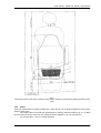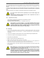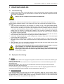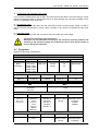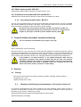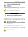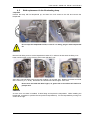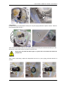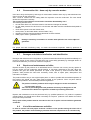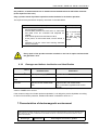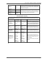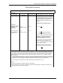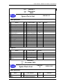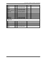
1
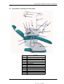
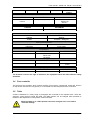
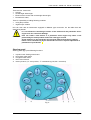
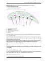
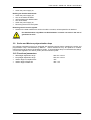
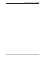
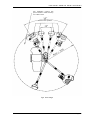
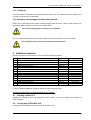
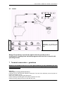
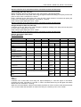
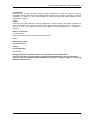
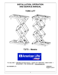
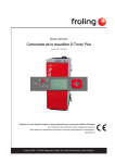
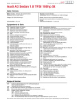
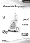
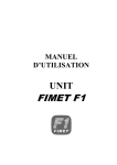
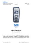
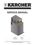
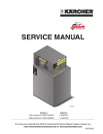
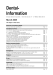
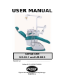
USER MANUAL Dental unit US-02.1 and US-02.3 Serial no: ............................................. Edition 5.01/ KOZN 374/2005 Żywiecka Fabryka Sprzętu Szpitalnego FAMED S.A. User manual – dental unit US-02.1 and US-02.3 Appendixes: 2, 3, Page 2 User manual – dental unit US-02.1 and US-02.3 This product complies with type category IIa in accordance with the European Medical Device Directive (MDD) 93/42/EEC, June 14th 1993, Appendix 9. The Manufacturer declares that this product conforms to the basic requirements of the MPG, Appendix 7, and documents conformity by marking this product with “CE”. Producer: FAMED S.A. Ul. Fabryczna 1 34-300 Żywiec, Poland Tel. +48 33 866 62 53 Infoline: (+48 33) 866 63 75 (24-hours a day) Fax +48 33 861 46 78 [email protected] www.famed-zywiec.com, www.famed.com.pl Medical device was registered at Registration Office of Healing Products, Medical Products and Bio fight Products in 18.09.2003 under no: PL/ DR 00 22 32 Page 3 User manual – dental unit US-02.1 and US-02.3 Dear Customer! Please, read this user manual carefully because it contents the important information and remarks of the manufacturer concerning proper product installation, usage and conservation. We congratulate you on good choice and wish satisfaction with exploitation of our merchandise. Żywiecka Fabryka Sprzętu Szpitalnego FAMED S.A. General notes • • • • The use, maintenance as well as servicing of this product performed in other ways than those, which have been stated in this manual is forbidden and may result in damages, which will encumber the user and which will not be a matter of producer’s responsibility. When the operation and parameters of the product do not match the description in item ‘Operation’ in this manual, the use of the product is not allowed and any defects have to be reported to the producer or the supplier. Every repair of the product must be done by a factory or an authorized service (the list of service companies enclosed in appendix 1) and recorded on the list of repairs, which is supplied with the guarantee certificate. Disregarding this requirement will cause the guarantee for the product to be invalid. Before starting any repairs the table must be disconnected from mains. Notes concerned with safety The sign shown below says: ‘Caution – pay special attention to the Operating Manual’. A label showing this sign is placed on any parts or mechanisms, which may prove to be harmful to the patient or the personnel if their operation does not comply with the descriptions found in this Operating Manual. • Do not connect the unit to mains in places where there is a danger of an explosion! • Use of accessories, additional equipment, cables or spare parts other that those offered and/ or advised by the producer may cause an increase of emission and/ or decrease of bed resistance to all electromagnetic phenomena. • Be careful when activating the pneumatic arm of the table of the unit. Moving elements (moved by a pneumatic spring) may catch your fingers or hand. It is not allowed to put hands or fingers on elements located close to moving elements of the structure. . Notes concerning: start-up, operation and maintenance Page 4 User manual – dental unit US-02.1 and US-02.3 • While blockade is on a table position cannot be changed since it can lead to blockade damage. • Use distilled water only! Otherwise handpieces may get damaged and it results in lost of guarantee. • Tool’s terminals will not work until the distilled water cycle is OFF • The terminals can not be used without tools. • Electrical micro-motor must not be lubricated. Notes concerning cleaning and disinfecting • • • • The product must not be disinfected in disinfection chambers! No bleaching agents (containing active chlorine or oxygen), caustic or corrosive chemicals are allowed! No agents destroying the structure of plastic (organic solvents) can be applied to the plastic elements! Before disinfecting disconnect from power socket. Disregarding the above requirements concerning cleaning and disinfecting shall result in losing the guarantee for the product! Page 5 User manual – dental unit US-02.1 and US-02.3 Content 1 PROPER USE AND APPLICATION................................................................................................... 8 1.1 APPLICATION......................................................................................................................................... 8 1.2 GENERAL REQUIREMENTS......................................................................................................................... 8 1.3 DUTIES OF THE USER ............................................................................................................................. 8 1.4 TECHNICAL DATA................................................................................................................................... 8 1.5 DESCRIPTION OF ELEMENTS AND FUNCTIONS................................................................................................. 9 1.6 DESCRIPTION OF THE PRODUCT................................................................................................................ 10 1.7 SAFETY............................................................................................................................................. 10 1.8 CRITICAL PARAMETERS.......................................................................................................................... 10 1.9 ELECTROMAGNETIC COMPATIBILITY........................................................................................................... 10 2 TRANSPORT AND FIRST USE........................................................................................................ 11 2.1 TRANSPORT........................................................................................................................................ 11 2.2 UNPACKING AND FIRST USE.................................................................................................................... 12 2.3 START-UP.......................................................................................................................................... 15 3 USAGE AND HANDLING................................................................................................................. 16 3.1 UNIT FUNCTIONING................................................................................................................................ 16 3.2 EQUIPMENT FUNCTIONING:...................................................................................................................... 16 3.3 EQUIPMENT......................................................................................................................................... 17 3.4 FOOT CONTROLLER............................................................................................................................... 18 3.5 TABLE............................................................................................................................................... 18 3.6 CUSPIDOR BLOCK................................................................................................................................. 20 3.7 LAMP 20 3.8 INTERNAL DISTILLED WATER CYCLE........................................................................................................... 20 3.9 SCALER AND MECTRON POLYMERISATION LAMP........................................................................................... 21 3.10 FUNCTIONAL PARAMETERS.................................................................................................................... 21 3.11 COLLISIONS...................................................................................................................................... 25 3.12 OPERATION WHEN PLUGGED TO THE POWER NETWORK.................................................................................25 4 ADDITIONAL MODULES.................................................................................................................. 25 4.1 STARTING SET WU-01.0...................................................................................................................... 25 4.2 CURING LAMP FARO WU-02.0........................................................................................................... 25 4.3 SUCTION SYSTEM WU-03.0 (ADDITIONALLY SUCTION PUMP)..........................................................................26 4.4 ADDITIONAL SHELF FOR TOOLS WU-04.1................................................................................................. 26 4.5 TRAY FOR CURING LAMP WU-05.0......................................................................................................... 26 4.6 MODULE OF 6-WAY SYRINGE WITH LIGHT WU-08.0....................................................................................26 4.7 NEGATOSCOPE WU-11.0..................................................................................................................... 26 4.8 LIGHT MODULE 1-HOSE WU-18.0.......................................................................................................... 26 4.9 LIGHT MODULE 2-HOSE WU-19.0.......................................................................................................... 26 4.10 ULTRASONIC SCALER MODULE WU-20.0................................................................................................ 26 4.11 ELECTRIC MICRIMOTOR MODULE WU-21.0............................................................................................ 26 4.12 WATER HEATER MODULE WU-22.0...................................................................................................... 27 4.13 ADDITIONAL HOSE MODULE WU-23.0 AND WS-23.1...............................................................................27 4.14 ARM WITH PNEUMATIC BLOCK WU-38.1............................................................................................... 27 5 CONTROL CRITERIA OF PRODUCT CORRECT FUNCTIONING.................................................. 27 6 SERVICE........................................................................................................................................... 27 6.1 STORING............................................................................................................................................ 27 6.2 WASHING, DISINFECTING AND MAINTENANCE OF THE SURFACE OF THE UNIT .......................................................27 6.3 WASHING, DISINFECTING AND MAINTENANCE OF DENTAL TOOLS.......................................................................28 6.5 BULB REPLACEMENT IN THE ILLUMINATING LAMP......................................................................................... 29 6.6 CONSERVATION LIST – DONE ONLY BY A SERVICE WORKER:...........................................................................31 6.7 DAMAGES AND DEFECTS LOCALISATION AND IDENTIFICATION...........................................................................31 6.8 REPAIRS AND MAINTENANCE ACTIVITIES..................................................................................................... 31 6.9 LIST OF THE MAINTENANCE ACTIVITIES...................................................................................................... 31 6.10 DAMAGES AND DEFECTS LOCALISATION AND IDENTIFICATION........................................................................32 Page 6 User manual – dental unit US-02.1 and US-02.3 7 CHARACTERISTICS OF ELECTROMAGNETIC ENVIRONMENT................................................. 32 8 DENTAL UNIT IDENTIFICATION..................................................................................................... 35 6.2 NAMEPLATE........................................................................................................................................ 35 6.3 LABELS............................................................................................................................................. 36 7 TERMINAL CONSERVATION – GUIDELINES................................................................................. 36 Page 7 User manual – dental unit US-02.1 and US-02.3 1 Proper use and application 1.1 Application Dental unit US-02.1 and US-02.3 is destined for dental check-ups and procedures on adults, children and disabled on wheelchairs. 1.2 General requirements The product is intended to be used indoors. Required climatic conditions: temperature from +10 to +40ºC, acceptable change of surrounding temperature during 8 hours should not exceed 20°C, relative humidity of the air should range from 30 to 80%, atmospheric pressure from 700 to 1060 hPa. The product should be used, maintained and serviced according to the indications of this manual. Using, maintaining and servicing the product in other way than indicated in this manual is not permitted and may lead to damages for which the user is to blame and for which the producer is not responsible. Caution! Installation of other accessories than those offered by the producer for the product is allowed only on the basis of a written acceptance of the producer. The Unit can not be used as hanger, stand, drill or vacuum. 1.3 Duties of the user User: any individual or corporate body who uses the product as its owner, lessee, pledge or who has a different right to the product as well as an entity who uses the product on its own or on whose behalf it is used. The user must ensure that the product shall be used exclusively in conformity with its destination and that it is used in appropriate conditions and in consistence with this manual. The user is also obliged to take all necessary precautions in order to prevent all life and health haza rds concerning the user, patients and any third party. Only authorised persons who underwent special training and are acquainted with this manual may operate the product. The user must also ensure that all persons who operate the product have read, understood and apply instructions contained in this manual. 1.4 - Technical data Power supply Value of a fuse on voltage 230V Power consumption (maximal) Input air pressure Filtration net on air filter on inlet Input water pressure Filtration net on water filter on inlet Water pressure in distilled water circulation Temperature of water for cup Maximum light illumination Maximum light illumination Saliva ejector efficiency weight Class of protection before electric paralysis Type of the part application Protection degree Usage period Maximal additional load of doctor’s table Maximal additional load of cuspidor block 230V~ 50/60Hz T3, 15 A 400 W 0,45 MPa 5 µm 0,25 MPa 80 µm 0.2 MPa 38°C ±5°C 25000 lux (for light EDI) 21500 lux (for light CELIA) 0,7 l/min by the water pressure 0.2MPa 65 kg I B IPX2 10 lat 3 kg 1 kg For the special cliente request it’s possiblr to produce the product with change parameters, not lowering it’s safety. Page 8 User manual – dental unit US-02.1 and US-02.3 1.5 Description of elements and functions FIG. 1 Pos. in fig. 1 1 2 3 4 5 6 7 8 9 10 11 12 13 14 Description Dental chair On / off switch Cuspidor block Cuspidor weight Cup filling point Saliva ejector Table’s pantograph arm Doctor’s table Steering panel Upper installed hoses Instruments Lamp’s pantograph arm Lamp On / off switch of lamp Page 9 User manual – dental unit US-02.1 and US-02.3 1.6 Description of the product The dental unit is installed on a dental chair. It can also operate independently (without the chair). A change of the height of chair causes a change of position of the unit thanks to which it is not necessary to adjust position of the unit after each change of height of the chair. The unit may be provided with a doctor’s table fixed on the arm which allows to position the table precisely. A set of tools (according to individual requirements of a client) and a panel which allows to control unit and armchair functions are located on the table. The unit may be provided with an assistant table. The unit may be provided with a shadowless lamp. Because of universality and module structure and a wide offer of accessories the unit can be set in various confgurations according to doctor’s specifications. The producer reserves the right to introduce in the product structural modifications resulting from technical progress which are not covered in this user manual. The producer reserve that all parameters and accesories can be modyfied or change, especially construction, technology and materials, not lowering accepted parameter technically-user and safeties of products. 1.7 Safety The structure of the product assures its safe operation and use on condition that the rules comprised in this manual are followed. Caution: The sign shown below says: “Caution – pay special attention to the User Manual”. A label showing this sign is placed on any parts or mechanisms, which may prove to be harmful to the patient or the personnel if their maintenance will not comply with the descriptions found in this Operating Manual. When operating the product the user has to pay attention to the elements and mechanisms marked as shown above. 1.8 1.9 Critical parameters Maximal input air pressure - 0,8 Mpa Maximal input water pressure - 0,6 Mpa Electromagnetic compatibility Medical device: dental unit US-02.1 and US-02.3 is an electric appliance. Electric appliances are a source of electromagnetic radiation and themselves are under its influence. Therefore, use of an medical devices requires some safety precautions connected with electromagnetic compatibility. In tables: item 7 Characteristics of electromagnetic environment – electromagnetic environment in which medical device dental unit US-02.1 and US-02.3 should be used is described. Recommendations and warnings which should be followed by the users were also presented. Page 10 User manual – dental unit US-02.1 and US-02.3 Use of different accessories, additional equipment, cables, spare parts than those offered and/ or recommended by the producer may cause an increase of emission and/ or decrease of bed’s resistance to all electromagnetic phenomena. Caution! Recommended distances between portable radio-transmitters and product 150 kHz to 80 MHz Rated output power of the transmitter in watts d =1,2 P [W] 0.01 0.1 1 10 100 distance in meters 0.1 0.4 1.2 4 12 150 kHz to 800 MHz 800 MHz to 2.5 GHz d =1, 2 d = 2,3 P P distance in meters 0.1 0.4 1.2 4 12 distance in meters 0.2 0.7 2.3 7 23 For transmitters whose maximum output power is not detailed above, the separation distance should be calculated on the basis of the formulas given above. P is the power in watts (W) as declared by the producer of transmitter ATTENTION The above recommendations may be inadequate in some situations. Propagation of electromagnetic waves can be absorbed or reflected from buildings, structures and people. 2 Transport and first use 2.1 Transport There is a possibility to transport the product by any covered transport means. While transporting, it is necessary to immobilize the truck and protect it against moisture. The transport conditions are as follows: from –10OC to 60OC (for the products including electronic parts), from –20OC to 60OC (the other products), - temperature: - relative humidity: from 20% to 80%. Caution! In case if unit is transported in temperature below zero degrees centigrade, all tanks and conduits containing water should be emptied. Water left in unit hydraulic systems during transport in freezing temperature may result in unit damage. While product transporting, storage and unpacking, the temperature gradient should be less than 10 OC per hour. It is strongly recommended to unpack the product after reaching room temperature. In case of products which comprise electronic systems when the difference between transport temperature and room temperature in which the product is located is considerable, the product should be left there for 12 hours. Only after that period it can be started. Laminar storage is permissible in accordance with the packaging marking. In the absence of the marking, storied storage is prohibited. In case of the specific transport conditions (particularly: low temperature transport), it is necessary to negotiate the way of transport and product packaging with the product manufacturer in order to ensure safe transport. Page 11 User manual – dental unit US-02.1 and US-02.3 2.2 Unpacking and first use 2.2.1 Unpacking The set is delivered to the customer disassembled. It is packed in wooden or cartoon boxes. Unpacking must be done inside a building as to protect the unit form damage. In order to make the unit ready to work the following must be done: • set the tray, • remove strips, • remove cartoon lid, • remove cushioning material, Package waste is recyclable and should be segregated before removed to a disposal site. Returnable packaging should be returned to the producer of the medical product. Caution! • carefully take the unit from wooden pallet and bring it into destined place 2.2.2 Installation of cuspidor block on the chair . Place the cuspidor on the chair arm. Protect it against turning using screws in the shank. Cuspidor’s axis of rotation must be vertical. A trained service worker must do the installation. After each displacement of the chair level the cuspidor block. Caution! 2.2.3 Lamp installation Remove cuspidor’s cover. Lead the power supply cable to the lamp holder and place the lamp in it. Connect the power supply cable to electronic circuit according to proper markers. A trained service worker must do the installation. Caution! 2.2.4 Table installation. Remove the table cover. Fix the table to arm with screws from the side of table metal plate and holder. Lead wires through the hole in the table metal plate and connect them to the electronic circuits according to proper markers. Connect water and sir pipes according to proper markers. Install the table cover. A trained service worker must do the installation. Caution! 2.2.5 Installing the unit The floor where that unit is installed must be stiff (otherwise there can be a problem with levelling of the unit). All connections are placed inside of dental chair’s base. There are connections for power supply water supply system, compressed air system and sewerage system. Page 12 User manual – dental unit US-02.1 and US-02.3 In order to connect the unit to the media (water, air, power, sewerage system) the connections int the floor should be made before installation (fig 2) All connections:: water ((valve which ends with an external thread ½’’, pos. 1 on fig 2), - sewerage system (Ø50, pos. 2 on fig 2) , - air ( pressure hose Øwew6mm/ Øzew12mm, pos. 3 on fig 2), power supply 230V 50Hz (electric wire 3x1.5mm2,in double insulation, length 500 mm from the floor), - suction pump (tube Ø32 elastic) - option, - suction pump steering (electric wire 2x0,5mm2, lengthć 500 mm from the floor i) – option, - possibility to disconnect voltage, must be placed in marked area. Connecting of sewerage system (Ø50) should be on floor’s level. Location of connections is free (in the range of pointed area) because of elastic connections in the chair. Additionally, on the fig. 2 the free space around unit is shown. In this area the floor should be free of obstacles in order to avoid collisions. The valve closing inflow fo water to unit should be used in order to protect against water leakage. Do not use drain trap on the connection to the sewerage system!. A trained service worker must do the installation. Caution! Page 13 User manual – dental unit US-02.1 and US-02.3 Fig.2 Chart with location of the chair in dental surgery and a drawing of connections against the basis of the chair 2.2.6 Media There are 2 basic kinds of media in dental unit : water and air. Air is being transported in blue hoses, water in green ones. The supply water must fulfil the requirements for drinking water according to § 2.1. of MOH Directive from 04.09.00 no 82. Pos. 937. Required water hardness is 60÷170 mg/l CaCO3 . Air must be clean – free of constant elements. Page 14 User manual – dental unit US-02.1 and US-02.3 Air can be provided to the unit from the compressor or from a central compressed air unit. Provided air can neither contain solids nor oil suspensions and because of that use of oil compressors is not allowed. In order to protect air system of the unit against water leakage the unit is provided with an air filter with a condenser. Filtering effectiveness 5μm. The filter has a system of automatic ejection of condensed water. Solids with size below 2 mm, sewage, microbiological substances are discharged to sewers. Caution! 2.2.7 - Preparation for start-up check whether the equipment provided fits the documentation enclosed, read the Operating Manual carefully, start up the product as described in item: 2.3 Installation and first use, Caution! 2.3 If the water doesn’t fulfil the above requirements, the user should supply outer water filter. If the air from compressor doesn’t fulfil the above requirements the filter of constant elements is recommended. If the product is not fully functional, i.e. the output parameters differ from the description contained in this manual, the bed must not be used. This situation should be reported to the producer or supplier (dealer). The use of an improperly functioning product may result in damages, which will encumber the user and which will not be a matter of producer’s responsibility. Start-up 1. The unit with chair should be placed on stiff floor in required working place, which meets the requirements descibed in this manual (item. 1.2 General requirements and 1.9 Electromagnetic compability). 2. If the chair is not stabile, the bottom plate of chair must be levelled using the adjustable foots. 3. Connect foot controller to the socket placed in chair’s base. 4. Fill the bottle with distilled water. • Make sure that the bottle with distilled water is full. • Make sure that valve which deliver the water to unit is open. • switch on the main switch on armchair cover 5 minutes after switching on of the compressor: air and water flow will open automatically and power will be connected to the unit. • After 10 minutes water in the heater reaches the required temperature and dental unit gets ready for exploaitation. Caution! Before putting into use ensure that the set is plugged in and check if the voltage in electrical installation is proper. Ensure also if the water and compressed air with an appropriate pressure are conducted to the unit. If the product is not fully functional, i.e. the output parameters differ from the description contained in this manual, the bed must not be used. This situation should be reported to the producer or supplier (dealer). The use of an improperly functioning product may result in damages, which will encumber the user and which will not be a matter of producer’s responsibility. Page 15 User manual – dental unit US-02.1 and US-02.3 3 USAGE AND HANDLING 3.1 • Unit functioning Turning on the main switch in the chair base (or in the connecting box) causes automatic opening of water and air supply. After 10 minutes water in a heater reaches adequate temperature and the unit is ready for exploitation. Always start the compressor first and the unit afterwards. . CAUTION! - Saliva ejector, suction terminals are placed on cuspidor block. In order to start the saliva ejector work the switch should be placed in “red” position (red point) and terminal should be taken out from the holder • There are buttons (described in the paragraph 3.5 “Table”) on the control panel board allowing flushing down the cuspidor and filling a cup with water. Short-duration pressing of the button will result in function operating for a period of time programmed earlier. Holding a button for more than 3 seconds does programming of glass filling or flushing time. Then the time that has passed starting from the moment of pressing and ending at the moment of releasing the button is programmed and stored. Next short-duration pressing of the button will result in function operating for a period of time programmed. • A lamp has 2 stages of illumination. The control is done through switch located at the rear side of lamp. Switching on the lamp is done by placing the switch in middle position. • The control of polymerising lamp is done through button located in lamp’s arm. The sound signal informs about half of working time. • Spray function is switched on by switch on foot controller (option) or under doctor’s table. Regulation of flow for each hose is possible thanks to knobs placed under the table (excluding the syringe) • When operation of the unit is finished it should be switched off with the main switch and the valve on water connection to the unit should be closed. Caution! 3.2 Little water leaking through the pipe used for filling the cup with water is not the sign of damage. It is caused by water dilatation while it is heated. After finishing the work the spray for instruments should be turned off. Not following this instruction can cause not big water leaking from hoses after turning off the power supply. Equipment functioning: 1. Syringe Pressing the button “water” on the syringe casing will cause water flow from its terminal. Releasing the button will stop the flow. Pressing the button “air” will cause the flow of compressed air from its terminal. Releasing the button will stop the flow. Pressing both buttons “water” and “air” at the same time will result in spray flow form its terminal. Releasing the button will stop the flow. In case of six-way syringe the heating option can be turned on and then pressing proper buttons will cause flow of appropriate mixture heated up to the temperature of about 36 o C 2. Electrical micro-motor Foot controller starts micro-motor after an arm with a terminal is taken out from the hanger. Micromotor revolution is changed through buttons “+” or “-“ located on the table panel board. Proper buttons (as described earlier in clause table) change the sense of rotation and turn on light in the terminal. Activation of any function is signalled through diode LED. Page 16 User manual – dental unit US-02.1 and US-02.3 3. Contra-angle and pneumatic micro-motor Foot controller activates these devices after arms with terminals are taken out form the hanger. Proper buttons (as described earlier in clause table) turn on a spray and light at the terminal. Activation of any function is signalled through diode LED 4. Piezoelectric scaler Foot controller activates scaler after arm with a terminal is taken out of the hanger. Power of scaler is changed through potentiometer in doctor’s table. Activation of any function is signalled through diode LED. 5. Pneumatic scaler Foot controller activates scaler after arm with a terminal is taken out of the hanger Caution! 3.3 The terminals cannot be used without tool. Setting the correct parameters according to the instruction from the producer and checking of the function working and instruments can be done by the worker of service during the installation. Equipment Equipment adviced by manufacturer: BIEN AIR Boralina Bora L Prestige L BIEN AIR MC3 IR MC3 LK NSK PA-SU-M4 PTL-II-SU Ti-Max A 600 Ti-Max A 600 L Ti-Max A 700 Ti-Max A 700 L NSK Ti-Max E Ti-Max EL Hand pieces Contra-angle turbines FARO W&H Delta P3 TE-95 RM Delta LP3 TA-98 TA-98 L SIRONA T1 T2 T3 Electric micromotors FARO SIRONA Intramatic Motor SL Intralux Motor EL 1 KAVO Gentleforce Supertorque KAVO Intramatic LUX Pneumatic micromotors NSK EX-203-M4 IS-205-M4 PTL-CD BIEN AIR CA 11 32 CA 11 L CA 15 41 CA 10 141 BIEN AIR PM 11 32 W&H A-25 LT-25 Contra-angles for micromotor NSK W&H SIRONA FPB-E WA-56 A Seria T1 Line NPB-PTL WA-56 LT Seria T1 Titan TI-25 WA-99 A Sironiti TI-25 LJ WA-99 LT TI-95 WA-86 A TI-95 LJ WA-86 LT NRS-E NRS-PTL Straight handpieces for micromotor NSK W&H SIRONA TI-65 HA-43 A Seria T1 Line EX-VI Seria T1 Titan Sironiti KAVO Gentlepower LUX Intramatic LH/CH Endoflash Duratec Multiflex KAVO Gentlepower LUX Intramatic LH/CH Endoflash Page 17 User manual – dental unit US-02.1 and US-02.3 Duratec Multiflex Scalers EMS FS-133 FS-273 MECTRON Piezo p2K SIRONA Siroson L Siroson C8 Stronic L Syringes LUZZANI Minilight SIE DENTAL C-1600 Curing lamp FARO Polispot Poliled MECTRON Starlight Compact + Starlight-P Hand polieshing device EMS Handyflow FIAC Ecu HP-1 ECOM DO-2.1 CL TREND Celia NSK Prochy Mate Compressors EKOM DK-50 Z DK-50 10Z DK-50 2V Suction pumps CATTANI Uni-Jet 75 Lighting lamps FARO Edi FAMED BM-25 DETAL CENTRA ARIA-1 A-004 SIE DENTAL Duo Dental The Producer reserves the right to introduce new equipment which will meet effective safety standards. 3.4 Foot controller The set has a foot controller, which controls working of micromotor, contra-angle, scaler and function of chip blower chair and the unit (option). It is connected to a terminal placed on the chair base. 3.5 Table A table is fastened to a rotary hinge of pantograph arm mounted to the cuspidor block. There are electronic control devices inside the table. The table position can be changed when blockade is released. After adjustment a new position must be blocked. While blockade is on a table position cannot be changed since it can lead to blockade damage. Caution! Page 18 User manual – dental unit US-02.1 and US-02.3 There are four hoses with: • Syringe. • Contra-angle without light • Electrical micro-motor with contra-angle witnout light, • Piezoelectric scaler, There is a possibility of adding following modules: • curing lamp module • negasoscope module Unit can work with all instruments equipped in Midwest type connection. On the table there are steering keyboards It is not allowed to interchange location of the turbine and the pneumatic microengine as it can cause their damage. CAUTION! User can install a new turbine or a pneumatic micro-engine only when a tool produced by the same producer and of the same type is used. A new turbine or a new pneumatic micro-engine different from those installed before can be installed only by an authorised service as it requires adjustment of parameters of provided air. Steering panel Steering panel (fig.2) has following functions: 1. 2. 3. 4. 5. cuspidor basin flushing down button warm glass water button cold glass water button chair control buttons memory buttons (“0”- zero position, “T”- trendelenburg, M1, M2 - memories) Fig. 3 Page 19 User manual – dental unit US-02.1 and US-02.3 Additional control panel (used when the unit is equipped in electrical micromotor) Function of additional control panel: • control of micromotor revolution, • micromotor revolution direction change, • handpiece light – turning on and off, • monitoring of micromotor speed with linear light bar. Fig.4. 1. 2. 3. 4. 5. 6. rotation decrease button [-] rotation increase button [+] light button rotation direction change button additional function light bar Underneath the table, water control valves for each hose are located (except for chip blower syringe). 3.6 Cuspidor block Cuspidor is located under left armrest and can be turned round the column fixed to the cha ir arm. From the patient side the porcelain, detachable bowl and glass container are located. The buttons on the steering panels of the table and assistant table are used for operating the cuspidor block e.g. filling the cup with water and cleaning the bowl. Saliva ejector is placed in holder on the side of cuspidor block. Suction system caniules are placed on rotary arm. Suction system and saliva ejector work automatically after taking out from holder. In case of using the curing lamp, it is placed on the side of cuspidor block . In cuspidorb block there is also module of internal circulation of distilled water. 3.7 Lamp Lamp rotary installed to the pantograph arm has two stages of illumination. The control is done through switch located at the rear side of lamp. Switching on the lamp is done by placing the switch in middle position. 3.8 Internal distilled water cycle The unit is equipped with distilled water cycle supplying tool’s terminals. It is placed inside cuspidor block. ON/OFF switch for the water cycle is located under the cuspidor’s cover. Switching the distilled water cycle on: • make sure the bottle is filled with distilled water, Page 20 User manual – dental unit US-02.1 and US-02.3 • switch the power supply on, Refilling the distilled water bottle • switch the power supply off • turn on the bottle clockwise • refill the bottle with distilled water • turn off the bottle, • switch the power supply on, • Removing the air from the system. Removing the air from the system. • Switch on the water outflow from each tool until the constant, uninterrupted flow is obtained. Use distilled water only! When not distilled water is used it can result in the lost of guarantee for tools. Caution! 3.9 Scaler and Mectron polymerisation lamp On customer’s demand unit may be equipped with general-purpose sleeve operating the scaler and polymerisation lamp manufactured by Mectron. These instruments may be replaced if needed. Instrument fixed to the sleeve is identified as scaler. If polymerisation lamp is connected to the sleeve, cut off water supplied to the sleeve (scaler) and set maximum power. 3.10 Functional parameters • • • • • table height adjustment range lamp height adjustment range rotation angle of cuspidor block rotation angle of lamp arm rotation angle of table arm 500 mm ±10 mm 520 mm ±10 mm >60° 300° ±10° 340° ±10° Page 21 User manual – dental unit US-02.1 and US-02.3 Page 22 User manual – dental unit US-02.1 and US-02.3 Page 23 User manual – dental unit US-02.1 and US-02.3 Unit installation minimal free space needed to table and lamp non-collision work Extreme arms positions fig 5 Arms range Page 24 User manual – dental unit US-02.1 and US-02.3 3.11 Collisions In some extreme unit positions a mechanical collision may occur. Thus attention must be paid that the unit and its elements are not damaged. 3.12 Operation when plugged to the power network Built-in into a chair base power supplier enables supplying the set with a current of 230V, 50Hz form the power network. Within the set only save voltage SELV. The unit must be plugged according to the nameplate. Caution! The unit is entirely detached from the power supply when the plug is taken out from the socket. Do not plug the unit in places where explosion hazard exists! Caution! 4 Additional modules Dental unit US-02.1 and US-02.3 can be enriched with following modules: 1 2 3 4 5 6 7 8 9 10 11 12 13 14 Module Start set Curing lamp FARO Aspirator system (additionally suction pump) Additional shelf for tools Curing lamp table 6 function chip blower syringe with light X-ray viewer Light module – 1 hose Light module – 2 hoses Ultrasonic scaler module Electric micromotor module Water heater module Additional hose module Additional hose module type WU-01.0 WU-02.0 WU-03.0 WU-04.1 WU-05.0 WU-08.0 WU-11.0 WU-18.0 WU-19.0 WU-20.0 WU-21.0 WU-22.0 WU-23.1 WU-23.0 for US-02.1 for US-02.1 for US-02.3 In case of ordering additional equipment the above types should be used. Assembly can be done only by authorised service worker. 4.1 Starting set WU-01.0 Starting set is added to each unit equipped in sution system, it is a set of single used endings od suction system. 4.2 Curing lamp FARO WU-02.0 Curing lamp is assembled on special holder on the side of unit. Page 25 User manual – dental unit US-02.1 and US-02.3 4.3 Suction system WU-03.0 (additionally suction pump) System of 4 sucking endings is mounted on special holder, raising of ending automatically switches on it’s work of the suction pumps. 4.4 Additional shelf for tools WU-04.1 Additional shelf for tools is mounted to the table 4.5 Tray for curing lamp WU-05.0 It is a tray for curing lamp. 4.6 Module of 6-way syringe with light WU-08.0 Module ensures proper working of 6-way syringe. 4.7 Negatoscope WU-11.0 Negatoskope module is mounted on table. 4.8 Light module 1-hose WU-18.0 Light module enables leading the light into the working end in one hose. 4.9 Light module 2-hose WU-19.0 Light module enables leading the light into the working end in two hoses. 4.10 Ultrasonic scaler module WU-20.0 Ultrasonic scaler is installed on the table, enables the ultrasonic scaler connection. 4.11 Electric Micrimotor module WU-21.0 Electric micromotor module powers electric motor of the end, which can be replaced by pneumatic micromotor. The unit is equipped with a system that informs user that end-piece maintenance is required. The system activates audio signal as soon as preset time has elapsed. Preset time ranges from 1 to 180 minutes. Setting change is possible through a terminal and may be done by a serviceman. Working time is counted separately for each end-piece sleeve. The system counts total end-piece working time and generates audio signal as soon as preset time has elapsed. In order to cancel audio signal, simultaneously press the push-buttons [+] and [-] on the accessory panel. As soon as the audio signal has been cancelled, time is counted from the beginning. Normally this system is inactive, however it may be activated by a serviceman on customer’s demand. This function is only informative and does not exempt the user from obligation to observe maintenance instructions specified in service manuals for end-pieces and in the maintenance guidelines provided in this manual. Caution! The unit is equipped with a system protecting against electric micro-motor overheating. According to its service manual, micro-motor is a device prepared for intermittent running, and e.g. for Bien Air micro-motor model MC3LK, its operation is as follows: - continuous running 1,7A; ok. 0,8Ncm; - intermittent running 3A for 60s; 5A for 10s; cooling within 3 minutes with air, or 20 minutes without air supply. When the above-listed parameters are exceeded, motor casing temperature excessively increases. Motor control system controls current consumed by the unit during operation. Audio signal announces exceeded parameters. Further micro-motor operation is still possible for a moment. In case of continuing motor overheating, it automatically deactivates. Further micro-motor operation is possible after having cooled it. Cooling is continued even if an end-piece is put aside and its duration depends on overload degree and may last even few minutes. Normally this system is active, however it may be deactivated by a serviceman on customer’s demand. Page 26 User manual – dental unit US-02.1 and US-02.3 4.12 Water heater module WU-22.0 Water heater module enables warming up of water till 38°C ±5°C. 4.13 Additional hose module WU-23.0 and WS-23.1 Additional hose module assure extension of sleeves and is installed on the table. 4.14 Arm with pneumatic block WU-38.1 The unit can be provided with an arm with doctor’s table with a pneumatic block. The arm is released with a button situated at the handle of the table. Then the doctor’s table can be moved up and down. When the button is released, the arm is blocked in chosen position. Be careful when releasing the pneumatic arm. Moving elements of table arm (moved by a pneumatic spring) may catch fingers or hands. It is not allowed to support or put fingers or hands in places marked with the symbol Caution! 5 Control criteria of product correct functioning The unit should be checked before first usage in each day. Caution! Way of checking the correct functioning: After the first put in use in any day the correct tools and equipment functioning should be checked according to the paragraphs “Unit functioning” and “Tools functioning”. If the unit passed positively all tests and there were not any worrying sounds, water leaking, sounds of escaping air, vibration, the unit may be safely used. Otherwise, see the point: “Damage and defects localisation and identifications”. Caution! If the product is not fully functional, i.e. the output parameters differ from the description contained in this manual, the bed must not be used. This situation should be reported to the producer or supplier (dealer). The use of an improperly functioning product may result in damages, which will encumber the user and which will not be a matter of producer’s responsibility. 6 Service 6.1 - Storing If the product will not be used for longer it should be stored in following climate conditions: temperature: 25o ± 10oC, relative humidity: 50% ± 25%. 6.2 Washing, disinfecting and maintenance of the surface of the unit For cleaning and disinfecting use cleaning solutions free from bleaching agents (active oxygen or chlorine), recommended by Famed S.A. in Annex 2 to this manual ( allowed to turnover and use on the territory of the country, where they are used). After disinfecting wash the product with distilled water to remove stains. After disinfecting dry thoroughly. Page 27 User manual – dental unit US-02.1 and US-02.3 Drying should be carried out by use of hot air (temp. max. 60o) or by wiping with a dry, soft, sterile clout. Caution! The product must not be disinfected in disinfecting chambers. Bleaching (containing active chlorine or oxygen), caustic and corrosive agents must not be used. No agents destroying the structure of plastic (organic solvents) can be applied to the plastic elements. Operating Personnel should check the condition and cleanliness of filtration sieve in the spittoon mug at least 2-3 times a day and clean them or replace when necessary. Operating Personnel should rinse the saliva ejector pipe 2-3 times per shift. Rinsing of saliva ejector pipe assures its proper operation. Caution! Disregarding the above requirements concerning cleaning and disinfecting shall result in losing the guarantee for the product! 6.3 Washing, disinfecting and maintenance of dental tools Only agents recommended by FAMED Żywiec S.A. in appendix no. 2 to this manual (whose sale and use is permitted in the country in which they are used) can be used for washing, disinfecting and maintenance of dental tools, even if producer of tools allows to use other agents. Washing, disinfecting and maintenance of dental tools should be done in accordance with tool operating manuals provided by producers. Having in view well-being of the client FAMED Żywiec S.A. developed the appendix ‘Washing, disinfecting and maintenance of dental tools: manual’ which comprises descriptions of washing, disinfecting and maintenance of offered dental tools. Using equipment elements incongruously with the user manual provided by the producer will result in the loss of guarantee. FAMED Żywiec S.A. is not responsible for effects of use of agents for washing, Caution! disinfecting and maintenance which are not on the list of recommended agents included in appendix no. 2. 6.4 Washing, disinfecting and maintenance of additional accessories Additional accessories shall be washed, disinfected and maintained in accordance with the operating manual provided by the producer. All maintenance activities which secure correct operation are described in operating manuals of particular elements of accessories. Using compressor incongruously with the user manual provided by the producer will result in the loss of guarantee. Caution! Page 28 User manual – dental unit US-02.1 and US-02.3 6.5 Bulb replacement in the illuminating lamp Lamp EDI Position the lamp with its lampshade up, and then turn lock screws to the left and remove the lampshade. Do not wipe the lampshade inside, in case if it is dusty, purge it with compressed air. Caution! Remove bulb fitting as soon as the lampshade is taken off, in order to do that catch the fitting in its lower part (as shown on the picture), softly press and take it out. After taking out bulb fitting remove the bulb, holding it in its lower part. Replace removed worn bulb with a new one (17 V, 95 W). Remember to hold the new bulb through a clean cloth. Never touch the bulb with bare fingers, as grease left on its surface will lead to its prompt wear. Caution! As soon as a new bulb is installed, fix bulb fitting and replace the lampshade. While installing the lampshade, remember to position the lamp with its lampshade up. Fix the lampshade by turning lock screws to the right. Page 29 User manual – dental unit US-02.1 and US-02.3 Lamp CELIA In order to remove the lampshade carefully turn it by 90°, paying attention to plastic catches. Remove the lampshade after turning it. Then unscrew bulb fitting. Remove worn bulb, holding it in its lower part. Hold the new bulb (12 V, 50 W) through a clean cloth and put it in place of the worn one. Never touch the bulb with bare fingers, as grease left on its surface will lead to its prompt wear. Caution! Then screw in bulb fitting, replace the lampshade and turn it by 90°, paying particular attention to catches. Page 30 User manual – dental unit US-02.1 and US-02.3 6.6 Conservation list – done only by a service worker: User has to obey the frequency and range of conservation activities done only by authorised services. User must pay for the inspections. After 3 and 12 months from the selling date the inspection must be conducted. The user should declare the inspection necessity. The neccesity of providing the conservation should be demanded by user ! The following must be done: • air and water filters in a chair base must be checked and changed as needed, • air and water pressure for each tool in a chair base and table must be controlled and adjusted as needed, • clean saliva ejector hose and Venturi valve, • check power, air and water leads, remove bands, if any • operation of all the control and steering elements must be checked, • make proper notes in guarantee card. Damages caused by incrustation or another water pollution are not the object of guarantee. Caution! For proper and safe functioning every 12 moths the technical inspection made by producer or authorised service shop (on the user’s account) must be done. It should contain the conservation activities conducted by the authorised service. 6.7 Damages and defects localisation and identification Damages and defects found in the product or product accessories should be reported immediately to a person in charge of such issues. The bed which can not be safely operated (e.g. damaged electric or mechanical elements ) must not be used till it is repaired. 6.8 Repairs and maintenance activities. Repairs are done by the his own unless he has producer has given his producer shall provide information on repairs. producer or an authorised service. The user can not carry out any repairs on undergone special training or has been authorised to do that. When the written permission for repair of the product by client’s technical staff, the the client with necessary charts, lists of spare parts, descriptions and The producer allows only to use original spare parts. In order to provide safe and reliable operation of the product one should use only spare parts provided by the producer. Worn out parts shall be removed as provided in environmental protection regulations. The product contains products which may be dangerous to the environment: Caution! - oil (pneumatic spring), The rules of proceeding with used products which may be dangerous to the environment are defined in regulations related to proceeding with waste. Repairs and maintenance must be performed only by qualified personnel. If a product is operated outside Poland, one should inform about a necessity of a repair a producer or the dealer from whom the product was purchased. Every repair of the product must be recorded on the list of repairs enclosed with the guarantee certificate. 6.9 List of the maintenance activities In order to ensure safe and proper technical condition of the product during the whole life of the product, the product should undergo periodical technical inspections to be carried out by Page 31 User manual – dental unit US-02.1 and US-02.3 the producer, an authorised service or authorised and trained technical staff of the customer (at the expense of the user). Only a positive result of product inspection can be the basis for its further operation. The required surveys and their frequency are shown in the table below. • • • • • • Survey’s subject air and water filters in a chair base must be checked and changed as needed,; air and water pressure for each tool in a chair base and table must be controlled and adjusted as needed, clean saliva ejector hose and Venturi valve, check power, air and water leads, remove bands, if any operation of all the control and steering elements must be checked, isolation of electric system must be controlled Frequency After 3 months and after 12 months after date of sale, and then every 12 months Every 3 years Every repair of the product must be recorded on the list of repairs enclosed with the guarantee card. Caution! 6.10 Damages and defects localisation and identification DEFEC Possible cause Elimination T Unit does not react Lack of power supply Switch the unit on Tool terminals do not work Lack of water in the terminals Lack of distilled water Switch the distilled water cycle on Lack of distilled water, Switched off the distilled water knob Switch the distilled water on, Refill the bottle with distilled water, Turn on the water regulation knob on the terminal If the fault cannot be eliminated, put the product aside and call the repair department, local service center or FAMED S.A’s service. If the customer resign from further product exploitation, he is obliged to product liquidation according to rules of environment protection, detailed information is situated in annex no. 3. 7 Characteristics of electromagnetic environment Medical device the dental unit US-02.1 and US-2.3 is to be used in electromagnetic environment specified below. The customer or the user of medical device the dental unit US-02.1 and US-2.3 should assure that it is used in such an environment. Emission type Classification Electromagnetic environment – guidance Page 32 User manual – dental unit US-02.1 and US-02.3 emission RF CISPR 11 Group 1 emission RF CISPR 11 Class B Harmonic emission IEC 61000-3-2 Class A Voltage fluctuation, flickering IEC 61000-3-3 Complies Medical device the dental unit US-02.1 and US-2.3 produces energy with radio frequency only for its internal function. Therefore, its RF emission are very low and are not likely to cause any interference in nearby electronic equipment.. Medical device the dental unit US-02.1 and US-2.3 is suitable for use in all establishments, including domestic establishments and those directly connected to the public low-voltage power supply network that supplies buildings used for domestic purposes. Electromagnetic immunity Medical device the dental unit US-02.1 and US-2.3 is to be used in electromagnetic environment specified below. The customer or the user of medical device the dental unit US-02.1 and US-2.3 should assure that it is used in such an environment. Immunity test Electrostatic discharge (ESD) IEC 61000-4-2 Surge IEC 61000-4-5 Series of quick transitory stages IEC 61000-4-4 Voltage dips, short interruption and voltage variations on power supply input lines IEC 61000-4-11 IEC 60601-1-2 Test level Compliance level ± 6 kV contact ± 6 kV contact ± 8 kV air ± 8 kV air ± 1 kV differential mode ± 1 kV differential mode ± 2 kV common mode ± 2 kV for power supply lines ± 2 kV common mode ± 2 kV for power supply lines ± 1 kV for input/ output lines < 5% UT (>95% dip UT) for 0.5 cycle ± 1 kV for input/ output lines < 5% UT (>95% dip UT) for 0.5 cycle 40% UT (60% dip UT) for 5 cycles 40% UT (60% dip UT) for 5 cycles 70% UT (30% dip UT) for 25 cycles 70% UT (30% dip UT) for 25 cycles Electromagnetic environment – guidance In the location of The dental unit US-02.1 and US-2.3 use the floor should be wooden, concrete or covered with ceramic tiles. If the floor is covered with a synthetic material, the relative humidity should be at least 30%. Mains power quality should be that of a typical commercial or hospital environment Mains power quality should be that of a typical commercial or hospital environment. Mains power quality should be that of a typical commercial or hospital environment. In normal use The dental unit US-01.2 is battery operated. Connect to mains network only for battery charging. < 5% UT < 5% UT (>95% dip UT) (>95% dip UT) for 5 seconds for 5 seconds NOTE UT is the a.c. mains voltage prior to application of the test level Page 33 User manual – dental unit US-02.1 and US-02.3 Electromagnetic immunity Medical device the dental unit US-02.1 and US-2.3 is to be used in electromagnetic environment specified below. The customer or the user of medical device the dental unit US-02.1 and US-2.3 should assure that it is used in such an environment. IEC 60601-1-2 Immunity test Compliance level Electromagnetic environment – guidance Test level Portable and mobile RF communications equipment should be not used not closer to any part of the dental unit US-02.1 and US2.3 including cables, than the recommended separation distance calculated from the equation applicable to the frequency of the trasmiter. Recommended separating distance: Transmitted disturbances induced by fields with radio frequencies IEC 61000-4-6 Electromagnetic field with radio frequency IEC 61000-4-3 3 Vrms 150 kHz to 80 MHz 3 Vrms 3 V/m 80 MHz to 2.5 GHz 3 V/m d =1,2 P d =1, 2 P 80 MHz to 800 MHz d =2,3 P 800 MHz to 2.5 GHz where P is the maximal output power of the transmitter in watts (W) according to the transmitter manufacturer and d is the recommended distance in meters (m). Field strengths from fixed RF transmitters, as determined by an electromagnetic site survey, a should be less than the compliance in each frequency range.b Interference may occur in the vicinity of equipment marked with following symbol: a Field strength from fixed transmitters, such as base stations for radio (cellular/cordless) telephones and land mobile radio, amateur radio, AM and FM radio broadcast and TV broadcast cannot be predicted theoretically with accuracy. To assess the electromagnetic environment due to fixed RF transmitters, an electromagnetic site survey should be considered. If the measured field strength in the location in which medical device the dental unit US-02.1 is used exceeds the applicable RF compliance level above medical device the dental unit US-02.1 and US-2.3 should be observed to verify normal operation. If abnormal performance is observed, additional measures may be necessary, such as reorienting or relocating medical device the dental unit US-02.1 and US-2.3. b Over the frequency range 150 kHz to 80 MHz, field strength should be less than 3 V/m. NOTES At 80 MHz and 800 MHz, the higher frequency range applies. These guidelines may not apply in all situations. Electromagnetic propagation is affected by absorption and reflection from structures, objects and people. Page 34 User manual – dental unit US-02.1 and US-02.3 8 Dental unit identification When sending/ asking any questions concerning the table and when ordering spare parts, please give the serial number of the table placed on the nameplate and the guarantee certificate. The nameplate is located on the lower part of the backrest plate. 6.2 Nameplate Description of individual components of the nameplate 1 - Producer’s name, trademark (address), 2 - Symbol (name) of the product, 3 - Serial Number (country of manufacture), 4 –Product index 5 - Caution! – read the User Manual, 6 - CE Mark 7 – Power feed parameters 8 – Kind of work (after each 2 min of work, 18 min. of break) 9 – Description of the application part, class of protection from electric shock and additional markings, IP-X2 Protection degree Application part type B Page 35 User manual – dental unit US-02.1 and US-02.3 6.3 Labels OR 1 See point 8.1 2 Nameplate Description of controls and adjustments under the doctor’s table. Notice! The producer reserves the right to introduce in the product modifications resulting from technical progress which are not covered in this operating manual. 7 Terminal conservation – guidelines Attention! This guideline treat only as a help. Before beginning of tools exploitation the user manuals attached to them should be read. Using the tools incongruously to them may result in the loss of guarantee. BIEN AIR Turbine (Bora, Prestige, Black Pearl Eco): Lubricate once a shift using the lubricator Lubrimed ®. The end of the lubricator put into the place of turbine and rotate at ½ turn. Clean once a week using the agent Spraynet ®. Internal cleaning: lead the agent in the turbine propulsive air canal. External cleaning: spray and remove dust with the cloth. Page 36 User manual – dental unit US-02.1 and US-02.3 Attention! Before each sterilisation turbine should be cleaned and lubricated. Contra-angle (CA 1132, CA 1141) Before lubrication take the head away from the contra-angle. Lubricate separately. Shank – lubricate once a day, after work using the agent Lubrifluid ® leading in the spray end into the place of micro-motor. Lubricate for 1 second. Head – lubricate once a shift, twice a day, once for each 15-20 minutes of constant work putting the head into the Lubrifluid spray applicator. Lubricate for 1 second. Clean with the agent Spraynet ® once a week. Attention! Before each sterilisation turbine should be cleaned and lubricated. Straight handpiece (PM 1123, PM 1132) Lubricate once a day, after work, using the agent Lubrifluid ®, leading in the spray end into the place of micro-motor. Lubricate for 1 second. Clean with the agent Spraynet ® once a week. Attention! Before each sterilisation turbine should be cleaned and lubricated. Electric micro-motor (MC2, MC3): Do not lubricate!!! Preparation Contents Order no Usage Tools Turbines with air bearings Turbines with ball bearings Electric motors BASCH Contra-angles and straight handpieces Sleeves BA 71 Spraynet Lubrimed Lubrifluid 100 ml 6 pcs. 500 ml 500 ml 107.50.01 107.37.01 930.01.21 930.01.23 Conservation Lubrication Lubrication External Internal Disinfection Sterilisation cleaning cleaning * * * * Microsurgical cables Drop wires, lock connectors Electronic systems Electric micro-motors MC2 Electric micro-motors MC3 Brush purge with a compressed air * * * * * * * * * * * * * * * * With cloth With cloth With cloth With cloth With cloth With cloth * * * * * * * * NSK Turbine: Lubricate once a shift, after work using the agent Panaspray ®. Lead the agent in the turbine propulsive air canal. Lubricate for 1 second. In case of dirt lubricate as long as the agent will outflow without the dirt. Lubrication = cleaning. When the oil is used lead 2-3 drops in the turbine propulsive air canal, connect to the sleeve and start it for 1 minute. When the lubrication is made in this way it is necessary to do it once a week. Page 37 User manual – dental unit US-02.1 and US-02.3 Contra-angle: Lubricate once a shift, after work using the agent Panaspray ®. Lead the agent in using the appropriate end (provided with the contra-angle) into the place of micro-motor. Lubricate for 1 second. Lubricate for 1 second. In case of dirt lubricate as long as the agent will outflow without the dirt. Lubrication = cleaning. FARO Turbine: Lubricate once a shift, after work using the agent Faro. Lead the agent in the turbine propulsive air canal. If the turbine has a lock connector lead the agent using the appropriate end. Lubricate for 1 second. In case of dirt lubricate as long as the agent will outflow without the dirt. Lubrication = cleaning. Electric micro-motor: Do not lubricate!!! Clean every three months in the authorised service shop. Others Piezoelectric scaler: Do not lubricate!!! Syringe: Do not lubricate!!! End remarks Using appropriate conservation agent is the guarantee of tool infallible work. If the tool will not be used for longer it should be cleaned and stored in the dry, warm place. The tool work must be immediately stopped when strange, unnatural sounds or too strong vibrations are perceived. Page 38 User manual – dental unit US-02.1 and US-02.3 Item: US-02.1 Editi on : December 2003 Spare Parts List SJW-4-01-02 Basic spare parts No Name 1 2 3 4 5 Electro-magnetic valve Venturi valve Holder of suction section Tip of suction section Pressure regulator Sieve with a cup for 6 suction device 7 Regulation valve 8 Catch 9 Electro-magnetic valve 10 Keyboard 11 Bottle PET 12 Water filter Qt Code number Cat. 3 1 1 1 1 S097413S0000010 S097413M0002125 S097413D1010360 S097413D1013600 S097413D1018350 1 2 2 1 2 1 3 2 1 1 1 1 S097413T0005312 S097413D1015110 S13622900001100 S097413S0000110 R60060-US0201001 S097413A1001000 S097413D1015260 Qt. Code number 1 1 1 S097413T0005312 S097413D1001513 S13622900001100 1 S06532080120003 Remarks 2 2 1 1 1 2 1 Repair kit No Name 1 Sieve ( strainer ) 2 Grey button 3 Plast. Catch Pressure tap screw 4 M8x12 Item: US-02.3 Editi on : December 2003 Spare Parts List Remarks SJW-4-0102 SJW-4-01-02 Cat. Remarks Basic spare parts No 1 Name Electro-magnetic valve Qt 3 Code number S097413S0000010 1 Page 39 User manual – dental unit US-02.1 and US-02.3 2 Venturi valve Holder of suction 3 section Tip of suction 4 section 5 Pressure regulator Sieve ( strainer ) 6 with a cap 7 Catch - white colour 8 Regulation valve 9 Anti-reverse valve 10 Keyboard 11 Bottle PET 12 Water filter 1 1 1 3 1 S097413M0002125 S097413D1010360 S097413D1013600 S097413D1018350 2 2 1 1 1 1 S097413T0005312 S13622900001100 S097413D1015110 S097413D1001806 R60060-US0201001 S097413A1001000 S097413D1015260 Qt. Code number 1 1 1 S097413T0005312 S097413D1001513 S13622900001100 1 S06532080120003 2 2 1 2 2 2 1 2 1 2 1 Repair filter No Name 1 Sieve (strainer) 2 Grey button 3 Plast.catch Pressure tap screw 4 M8x12 Remarks Page 40