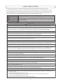
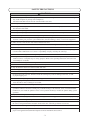
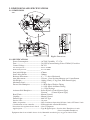
1
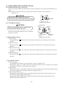
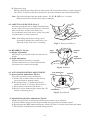
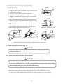
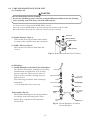
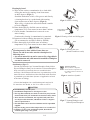
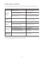
DENTAL UNIT AND CHAIR
OPERATING INSTRUCTIONS
IMPORTANT
This manual provides operating instructions for VOYAGER-II L.
The instructions contained in this booklet should be thoroughly read and
understood before operating the unit and chair.
File this manual and refer back to it for future maintenance.
0197
TABLE OF CONTENTS
Page
SAFETY PRECAUTIONS------------------------------------------------------- 1
1. OVERALL VIEW AND MAJOR COMPONENTS---------------------------- 5
2. DIMENSIONS AND SPECIFICATIONS
2-1. DIMENSIONS----------------------------------------------------------------- 6
2-2. SPECIFICATIONS------------------------------------------------------------ 6
3. OPERATING INSTRUCTIONS FOR UNIT
3-1. MASTER SWITCH----------------------------------------------------------- 7
3-2. DOCTOR TABLE SECTION------------------------------------------------ 7
3-3. CUSPIDOR SECTION------------------------------------------------------- 8
3-4. ASSISTANT INSTRUMENT HOLDER SECTION---------------------- 9
3-5. FOOT CONTROL SECTION------------------------------------------------ 9
3-6. SWING ARM SECTION----------------------------------------------------- 9
3-7. DOCTOR TABLE SAFETY LOCK DEVICE----------------------------- 9
4. OPERATING INSTRUCTIONS FOR CHAIR
4-1. MAIN SWITCH-------------------------------------------------------------- 10
4-2. CONTROLS------------------------------------------------------------------- 10
4-3. SAFETY LOCK DEVICE--------------------------------------------------- 11
4-4. HEADREST OPERATIONS------------------------------------------------ 11
4-5. AUTO MODE POSITION ADJUSTMENT------------------------------ 11
5. RIGHT/LEFT HANDED DENTISTRY CONVERSION-------------------- 12
6. CARE AND MAINTENANCE
6-1. CARE AND MAINTENANCE FOR CHAIR---------------------------- 12
6-2. CARE AND MAINTENANCE FOR UNIT------------------------------ 13
7. BEFORE ASKING FOR REPAIRS---------------------------------------- 17
8. MAINTANANCE AND INSPECTION----------------------------------- 18
9. ELECTROMAGNETIC COMPATIBILITY----------------------------------- 21
10. LIST OF COMPATIBLE HANDPIECES ------------------------------------- 23 Intended Use of the Product
This product is an active therapeutic device intended for the exclusive use for diagnoses,
treatments and relative procedures of dentistry.
The product must be operated or handled by the qualified dentists or by dental staffs under
the supervision of the dentist.
Such dentists or dental staffs should instruct and/or assist the patients to approach to and
leave from the product.
Patients should not be allowed to operate or handle the product unless he/she is so instructed.
The product is supplied together with the handpieces like electric micromotor, air turbine
and/or motor, scaler and so on.
Environmental Requirements
Ambient Temperature
Operating +5℃ - +40℃
Humidity 10 % - 80%
Storage -10℃ - +50℃
Atmospherical Pressure 600 hPa - 1060 hPa
Compatibility of Handpieces
Use the compatible handpieces as shown on the attached list for this unit. (List of compatible
handpieces).
Important Notes
In case of the troubles, please contat Takara Belmont offices or your dealers.
Do not disassemble or attempt to repair.
Disassembly, repair or modifications shoud only be done by a qualified repair technician.
Attempts at disassembly, repair or modifications may lead to abnormal operation and accidents.
Disposal of residue material
Please request a special contractor when you dispose amalgam.
In case of disposal of equipment
When disposing the unit and chair, appropriately dispose complying with all current
applicable regulations and local codes. In EU area, EU directive 2002/96/EC on waste electrical and electronic equipment (WEEE) is applied on this product. In this directive, environment conscious recycling/abandonment is obligated.
SYMBOLS
Protective earth
(ground)
Alternating current
ON (power)
OFF (power)
Chair last position
Chair auto return
Chair preset1
Chair preset2
To raise the chair
To Recline
the backrest
To lower the chair
To raise
the backrest
Air
Non-ionizing
radiation
Authorized
representative in
the European
community
Type B
Applied Parts
Water
㸶
Manufacturer
Date of manufacture
㻨㻦
Caution
It means “caution,
warnings, or
possibility to
danger”.
Separate
collection for
electrical and
electronic
equipment
Chair manual
control
㹌
㻵㻨㻳
Autoclave Symbol
This symbol on
component means that
the component can be
sterilised with an
autoclave at 135℃ max.
Refer to instruction
manual/booklet
SAFETY PRECAUTIONS
For proper operation, please carefully read through the Safety Precautions before using the product.
Items described herein are provided in order to ensure safe and appropriate use of the product, and to prevent
property damage or personal injury to the operator and other persons. Furthermore, the precautions describe
potential hazards due to improper handling and classify hazards according to degree of damage and level of
urgency. Please be sure to read the items and precautions as they both relate to safety.
Division of caution level Magnitude of danger and damage and extent of urgency
WA R N I N G
CAUTION
NOTICE
This word refers to precautions that if ignored may result in fatal or serious injuries.
This word refers to precautions that if ignored may result in minor or moderate injury
or property damage.
This word refers to precautions regarding safety.
WA R N I N G
1. Be sure to switch off the breaker for the equipment when it will not be in use for a long period of time.
When the equipment will not be in use for a long period of time, such as at the end of the day or a non-business
day, be sure to switch off the applicable breaker in the office and disconnect the power plug from the outlet.
Failure to heed this warning may result in electrical leakage or fire due to deterioration of insulation.
2. Be sure to turn off the main switch at the end of the day and during break times.
Be sure to turn off the main switch at the end of the day and during break times. This will prevent
malfunctions and resulting hazards due to accidental contact with the equipment.
3. Do not attempt to disassemble, repair or modify the equipment.
Only authorized personnel should disassemble, repair or modify the equipment. Failure to heed this
warning may cause an accident, failure, electrical shock, or fire.
4. Be sure to ground the equipment
Be sure to ground the equipment firmly and correctly. (To ground the equipment, contact a qualified
technician.) Failure to heed this warning may result in electrical shock during failure or electrical leakage.
5. Pay attention when exposing the equipment to electromagnetic interference.
The product may malfunction when exposed to electromagnetic interference. Do not install the product
close to communication equipment or an elevator that generates electromagnetic waves. In addition, do not
use devices such as a mobile phone that generates electromagnetic waves in the vicinity of the product.
6. Be sure to turn off the main switch when a high frequency surgical instrument (HF-Surg) is used.
Use of a HF-Surg may cause the equipment to malfunction due to generated noise. Be sure to turn off the
main switch when using the HF-Surg.
7. Use caution towards patients with a pacemaker.
Use caution towards patients with a pacemaker. If the patient experiences anything unusual while
product is operating, immediately turn off the power of the product and discontinue use.
8. Never fail to carry out maintenance and inspections.
Using the product without performing maintenance and inspection programs may result in bodily injury or
property damage. Refer to the section for maintenance and inspections.
9. Be sure to mount the mirror cover.
The mirror cover for the dental light must be attached whenever the light is used. Touching the light bulb may
result in burns. Refer to the operating instructions on the dental light for details.
10. Be sure to turn off the power when replacing the light bulb.
The power must be turned off when replacing the dental light bulb. Failure to heed this warning may result
in electrical shock.
The specified halogen light bulb must be used.
The bulb and the bulb holder may be hot. Wait until they become cool before replacing the bulb.
Do not touch the halogen bulb with bare hands.
Refer to the operating instructions on the dental light for details.
-1-
SAFETY PRECAUTIONS
WA R N I N G
11. Do not place articles weighing 3 kg or more on the instrument table.
Do not place articles weighing 3 kg or more on the instrument table. Failure to heed this warning may
result in breakage, malfunction of the table, or an accident.
12. Do not apply excessive force to the arms.
Do not mount or apply unnecessary force to the unit arms or the armrests of the patient chair. Failure
to heed this warning may cause an accident or the unit to tip over.
13. Do not sit on other than seat
When the backrest is at the forward position. do not sit on or place an undue load on the headrest or legreat
of dental chair. This could cause the unit to topple or could damage the unit.
14. Do not place a load on the top of the unit.
Do not get on, sit on or place heavy objects on the top of the unit. Damage to the top of the unit may result
in physical injury.
15. Immediately wipe off any water spills or leakage on the floor
Immediately wipe off any water spills or leakage on the floor.
Decreased strength of the floor may lead to physical injury including fall, or property damage.
16. Take action for power fail
Shut down the main switch of Doctor`s table after power fail recovery due to avoid the unexpected movement.
CAUTION
1. The system must be operated or handled by a qualified dentist or by dental staff under the supervision of a dentist.
Persons other than dentists or other dental professionals must not use the system.
2. Check safety before operating the product.
Before operating the system, be sure to check that all parts operate normally and safely, and that there are no
obstacles in the area.
3. Pay attention to the patient and children.
Be careful to avoid accidents due to mischief or careless operations by the patient (children in particular).
Keep an eye on the patient.
4. Stop operation of the system when feeling something is wrong.
During inspections, pay attention to any looseness, wobbling, inclination, vibration, abnormal sounds,
temperatures, or odors. If something is out of place, even slightly, immediately stop operating the system.
5. Do not strongly hit or scrape the system.
Do not strongly hit or scrape the system. Failure to heed this caution may result in breakage of the cover or
malfunction of the system.
6. Be sure to operate the switches by hand.
Except for the footswitch, be sure to operate the switches by hand. Operation of switches by means other
than hands may result in breakage or system malfunction.
7. Take caution when using water other than city water.
The system is designed for use with city water. Use of water other than city water (such as water-line
sterilization system) may result in system failure.
8. Request for flushout of water staying in the unit
In order to maintain the quality of the treatment water to stably supply water to the handpieces, be sure to
thoroughly flush out any remaining water in the unit before starting treatment. Refer to the pages for the
flushing out procedures.
-2-
SAFETY PRECAUTIONS
CAUTION
9. Cautions when shifting/moving the instrument table:
When moving the instrument table, pay attention to the surrounding area. Failure to heed this warning
may result in injuries by the tips of the handpieces.
The instrument table must be moved with the handle of the unit.
10. Do not place hot objects on the instrument table.
Do not place hot objects on the instrument table. Failure to heed this warning may result in deformation or
discoloration of the table.
11. Do not place anything articles on the Doctor's table
Do not place anything articles on the Doctor's table when the table part is moved up and down.
12. Be sure to wipe chemicals off immediately when spilled on the system.
If chemicals or water are spilled on the system, immediately wipe off with a dry, soft towel. Failure to
heed this warning may result in system malfunction, electrical leakage, stains, or rust on the equipment.
13. Take care not to activate the water heater without water in it.
Activating the water heater without water in it will burn out the heating element, resulting in fire.
14. Be sure to use the cover over the scaler tip.
After using the scaler, be sure to use the designated tip cover (for models with a cover) before placing
it in the holder. Without the cover, there is a possibility of injury caused by the scaler tip.
15. Observe the following when handling handpieces:
Change the rotation speeds of the micro-motor and detach the burr of the handpieces only after motor
rotation comes to a complete stop for safety purposes. Refer to the operating instructions that come with
each handpiece for details.
16. Observe the following when handling the film viewer:
Handle the film viewer carefully, since a fluorescent lamp is encased. Be sure to turn off the lamp when not in use.
17. Pay attention the interference between table and chair
The cart type has no safety switch, so pay attention the interference between chair and unit when chair is moved.
18. Observe the following concerning the cart hose:
Do not tread on the cart hose. Failure to heed this warning may result in damage to the hose, as well
as people tripping over.
19. Cautions when adjusting the height of the cart-type instrument table:
After adjusting the height, be sure to fasten the loosened lock screw. Failure to heed this warning may
cause the table to shift, resulting in an accident.
20. Pay attention to entrapment during automatic operation of the treatment unit.
During automatic operation of the treatment unit, pay attention to surrounding areas before initiating
operations. Failure to heed this warning may result in breakage of the backrest, stool, or instrument table.
Furthermore, check that the patient is in the correct position and always monitor the patient during system
operation.
21. Pay attention during the headrest operation
Do not allow hands, fingers, or hair to become entangled in the moving parts of the headrest during operationg.
22. Precautions in handling of the gas burner
Keep the gas burner way from flammable materials. This may cause a fire.
Be sure to extinguish the flame and turn off the main valve when the gas burner is not in use.
23. Caution when cleaning the control panel (membrane switch):
Seepage of sterilization liquid into the back of the membrane sheet will cause switch failure. Be sure to use a
paper towel applied with sterilization liquid to clean the membrane sheet surface.
-3-
SAFETY PRECAUTIONS
24. Precautions for use of handpieces
CAUTION
Handpieces may have poor spraying performance or generate heat due to the lack of cooling water/cooling
air. In the case of the development of heat or an odor of something burning, immediately discontinue use
and contact the dealer or our company because burns may occur or dental pulp may be adversely affected.
25. Do not use the water cleaning filter in a setting where freezing is expected
Do not use the water cleaning filter in a setting where freezing is expected. Damage to parts may lead to
water leakage.
26. Observe the following when cleaning the Spittoon bowl:
Never use sandpaper, wire wool, or detergents containing abrasive compounds to clean the Spittoon bowl.
Do not use overly acidic or alkaline pipe cleaning agents, as they may corrode metals.
27. Caution when cleaning the plastic covers:
When cleaning the plastic covers, use only the desinfectant (Durr FD333) recommended by this company
or a diluted neutral detergent, or the plastic cover may crack.
After cleaning, make sure to wipe off all residue with a dry and soft cloth.
28. Air pressure of the clean water system (optional) must be less than 0.2Mpa.
The air pressure to the clean water system must be regulated to less than 0.2Mpa. Excessive pressure may
rupture the clean water system.
29. Do not use water for the clean water system (optional) other than purified water, distilled water or pure water.
For the clean water system use only purified water, distilled water or pure water.
Do not use such as mouth wash or electrolytic solution which may cause clogging in tubings or adverse
effect on inner valves and instruments.
30. Close the water main valve at the end of the day.
Make sure to close the water main valve at the end of the day to prevent a water leakage.
31. Read the documents accompanying the various pieces of equipment
Before use, be sure to carefully read the package inserts and Instruction Manuals accompanying the various
pieces of equipment (including optional articles) to ensure proper use.
1. Troubleshooting and contact information
NOTICE
In the case of any problems, discontinue use, turn off the main switch and contact the dealer or our company.
2. Operational check of the air compressor:
If air is not supplied to the product, the system will not function even if the main switch is turned on.
Before operating the product, turn on the power to the air compressor.
3. The air turbine must be of the type with a water check valve.
The air turbine must have a water check valve. If the turbine is not the correct type, contact your
dealer or our company.
4. Handling of the system during power failure:
If the system stops during operation due to a power failure, place the handpiece in the holder, and turn off
the main switch.
5. Function of the flow adjustment valve/knob
The function of the flow adjustment valve/knob is to regulate, not to stop, air/water flow.
Do not overly tighten the valve/knob or the knob may break.
-4-
1. OVERALL VIEW AND MAJOR COMPONENTS
1
2
20
3
4
13
12
11
5
16
17
9
19
21
10
18
14
8
7
15
Chair base front left
6
Fig.1-1 Overall View and Major Parts
MAJOR PARTS
13. Armrest
1. Light Pole
2. Cuspidor Bowl
3. Cuspidor Unit
4. Assistant Holder
5. Doctor Table
6. Doctor Arm
7. Doctor Arm Cover
8. Foot Control
9. Headrest
10. Backrest
11. Seat
14. Foot Switch
15. Power Switch
16. Pump Cover
17. J-Box Cover
18. Presuure Gauge
19. Stop Valve for Water
20. Dental Light 048-VG
21. Handpieces
(Micromotor, Air Turbine/Motor,
Scaler and etc.) Manufacturers recommend
to use the handpieces with CE markings
12. Seat Cover
-5-
2. DIMENSIONS AND SPECIFICATIONS
2-1. DIMENSIONS
-mm-
°
0°
°
280
350
170
675
85°
430
575
13
80
R4
60
13
0°
570
305
°
215
°
72
370
730
470- 850
10°
70°
480
1740
75
58
650
1205
2015
565
1365
Fig.2-1 Dimensions
2-2. SPECIFICATIONS
Power Consumption---------------------- AC230V, 50/60Hz, 3.7/3.7A
Fuse----------------------------------------- 5A/250V(Current Rating:50A at 250VAC) Fast-blow
Control Voltage--------------------------- DC12V
Air main pressure--------------------------- 0.45 to 0.5MPa
Water main pressure------------------------ 0.1 to 0.2MPa
Seat initial Height------------------------ 470mm
Seat Lifting Stroke----------------------- 380mm
Backrest Movement---------------------- 0˚ ~ 72˚ above Horizontal
Auto Movements------------------------- 2 Preset, 1 Last Position Memory and 1 Auto Return
Net Weight--------------------------------- 140 kg (Chair), 67 kg (Unit, With Dental Light)
Maximum Load--------------------------- 135 kg
Doctor Side Handpiece------------------ 1 x High Speed Turbine Tubing
1 x Low Speed Air Motor Tubing
1 x 3-Way Syringe
Assistant Side Handpiece---------------- Saliva Ejector (Central System Type)
Vacuum (Central System Type)
Bowl Flush-------------------------------- Manual Control
Cupfiller------------------------------------ Manual Control
Dental Light------------------------------- 048-VG Type
Service Life- ------------------------------ 10 years
Mode of operation -------------------------- Non-Continuous Operation ON time:3 min, OFF time:15 min
Classification of foot controller ----------- IPX1(applicable standard IEC60529)
Protection class against electric shock --- Class I equipment
Applied parts --------------------------------- Type B applied parts : Seat for chair, Handpiece for unit
(List of compatible handpieces)
Equipment that is not suitable for use in air, flammable anesthetic gas, oxygen or nitrous oxide
-6-
3. OPERATING INSTRUCTIONS FOR UNIT
Note : Before operation, confirm that air compressor
is fully charged.
The chair can be operated only when both the
chair main switch and the master switch are ON.
Refer to 4-1.
Master Switch
ON
MA
IN
OFF
ON
OFF
HP2
3-1. MASTER SWITCH (Fig.3-1 and Fig.3-2)
Turn on the master switch located under the doctor
table, the master switch indicator located on the front side of the cuspidor unit turns to green.
CAUTION
Turn off the master switch after daily operation.
3-2. DOCTOR TABLE SECTION
(1) Handpiece Spray Water Flow Control Knobs
(Fig.3-1)
The handpiece spray water flow control knobs
located under the doctor table provide for
individual adjustment.
Each handpiece spray water flow control knob
is lined up from the facing left hand side HP1, HP2...
Turning a flow control knob counterclockwise
increases flow volume and turning clockwise
decreases.
(2) 3-Way Syringe
A. 3-Way Syringe Operation (Fig.3-3)
Depressing either or both buttons, this syringe
offers air, water and spray.
Syringe tip can be rotated freely.
To remove syringe tip : Keep depressing the
lock ring and pull out the syringe tip.
To set syringe tip : Keep depressing the lock
ring, insert the syringe tip and release the lock
ring.
HP1
Handpiece Spray Water
Control Knobs
Fig. 3-1 Master Switch and
Handpiece Spray Water
Control Knobs
Master Switch
Indicator
Cuspidor Unit
Fig. 3-2 Master Switch Indicator
Syringe Tip
Lock Ring
Water Button
Air Button
Fig. 3-3 3-Way Syringe
B. 3-Way Syringe Flow Control Screws
(Fig.3-5)
Air and/or water flow of 3-way syringe can be
Flow Control
adjusted by the flow control screws located
Screw (Water)
bottom of the table.
Decrease
Increase
Facing right hand side screw controls air and
left hand side controls water.
Hex Key Wrench
Control
Turning a flow control screw counterclockwise Flow
Screw (Air)
increases flow volume and turning clockwise
decreases. Use the hex key wrench supplied. Fig. 3-4 3-Way Syringe Flow Control Screws
ON
IN
MA
OFF
HP2
-7-
HP1
(3) Removing Table Top (Fig.3-5)
Loosen 4-screws from the table bottom and
remove the table top.
The auto select valve and the handpiece
pressure gauge are located in the table.
Table Top Cover
(4) Handpiece Drive Air Adjustment Screws (Fig.3-6 & Fig.3-7)
Adjustment of drive air of each handpiece can
be made by the screw on the auto select valve.
It is important to set the drive air pressure
in according with the handpiece manufacture's
recommendation.
Drive air pressure is indicated by the handpiece
pressure gauge.
Note : Refer to 3-5 for handpiece control
Setting The Optimum Condition (Fig.3-7)
Turn the appropriate dive air screw fully
clockwise, then depress the drive air pedal of
the foot control fully (maximum foot pressure)
and turn the screw counterclockwise slowly.
Stop turning the screw immediately when the
handpiece pressure gauge shows the desired
drive air pressure.
(5) Handpiece Coolant Air Adjustment Screws
(Fig.3-6 & Fig.3-7)
Handpiece coolant air adjustment screws are
provided for individual adjustment of handpiece
coolant air. Turning a handpiece coolant air
adjustment screw counterclockwise increases
flow volume and turning clockwise decreases.
(6) Handpiece
Refer to handpiece manufacturers operating
instructions.
3-3. CUSPIDOR SECTION
(1) Cupfiller (Fig.3-8)
Keep pressing the cupfiller button until a cup is
filled with water.
(2) Bowl Flush (Fig.3-8)
Turn the bowl flush control knob counterclockwise,
water flushes into the cuspidor bowl.
Further turning counterclockwise, increases the
amount of flush water.
-8-
ON
MA
IN
OFF
HP2
HP1
Table Top
Fixing Screws
Fig. 3-5 Removing Table Top Cover
Auto Select
Valve
View A
HP1
HP2
Handpiece
Pressure
Gauge
(HP3)
Fig. 3-6 Auto Select Valve and
Pressure Gauge
Drive Air Screw
HP1 HP2
(HP3)
Coolant Air Screw
View A
Fig. 3-7 Auto Select Valve
Cupfiller Button
Decrease
Increase
Bowl Flush
Control Knob
Fig. 3-8 Cupfiller and Bowl Flush
3-4. ASSISTANT INSTRUMENT HOLDER SECTION
Pick up an instrument (Saliva Ejector or Vacuum
Handpiece) from the assistant instrument holder,
it starts working automatically.
Returning the instrument to the assistant instrument
holder stops it automatically.
Chip Blower Button
Drive Air Pedal
ON
OFF
3-5. FOOT CONTROL SECTION (Fig.3-9)
(1) Drive Air Pedal
Depressing the drive air pedal controls handpiece
rotation speed and coolant air on/off.
Spray Water
ON/OFF Switch
On
Off
Chip Blower Button
Coolant Water On/Off Switch
(2) Spray Water ON/OFF Switch
Spray water ON/OFF switch allows water to
be turned on or off.
Refer to 3-2 (1) of this manual for adjusting
water of each handpiece.
Drive Air Pedal
Fig. 3-9 Foot Control
(3) Chip Blower Button
By depressing the chip blow button, chip blower
comes out from handpiece without bur turning.
Upper Swing
Arm Post
Stopper Ring
(4) Safety Device by Foot Control
When the drive air pedal is being depressed and
handpiece is running, all the chair control switches
are inactivated.
This is to prevent the chair from unexpected
movement by any switch being touched accidentally.
Lower Swing
Arm
3-6. SWING ARM SECTION
Table Height Adjustment (Fig.3-10)
Hold and slightly lift up the doctor table, stopper
ring will come up on upper swing arm post.
Slide up or down the stopper ring to appropriate
groove on upper swing arm post.
Lower the doctor table to fix it at that height.
3-7. DOCTOR TABLE SAFETY LOCK DEVICE
(Fig.3-11)
If excess pressure (upward or downward) is
applied to the doctor table by the movement of
chair, safety device stops the chair movement to
protect the table from being damaged.
-9-
Fig. 3-10 Swing Arm
Upward
Doctor Table
Downward
Fig. 3-11 Doctor Table Safety
Lock Device
4. CHAIR OPERATING INSTRUCTIONS
4-1. MAIN SWITCH (Fig.3-1 & Fig.4-1)
Turn on the master switch located at the left side of the pump cover, main switch illuminates in
green.
Note : Chair main switch will not activate unless master switch of unit is turned on.
Refer to 3-1.
CAUTION
I (ON)
Operate the main switch only by hand.
Turn off the main switch after daily operation.
Fig.4-1 Main Switch
4-2. CONTROLS (Fig.4-2)
CAUTION
Before operating the chair, confirm safety
for the patient and the operator.
Main Switch
O (OFF)
All chair electrical movements can be controlled
by the foot switch.
Foot Switch Disc
Preset-2
Preset-1
2
1
0
Auto Return
LP
Last Position
Memory
(1) Manual Mode Control
Fig.4-2 Foot Switch
A. Seat Lifting
Keep depressing ( ) side of the foot switch disc until the seat is lifted up to the desired
position.
B. Seat Lowering
Keep depressing (
) side of the foot switch disc until the seat is lowered to the desired
) side of the foot switch disc until the backrest is rased up to the desired
position.
C. Backrest Reclining
Keep depressing ( ) side of the foot switch disc until the backrest is reclined to the desired
position.
D. Backrest Raising
Keep depressing (
position.
(2) Auto Mode Control
E. Preset Control
VOYAGER II chair has two preset positions. (Preset-1 and Preset-2)
Momentarily depress ( 1 ) button on the foot switch, the chair will move to the preset-1 position
automatically. (Preset-2 is operated by ( 2 ) button.)
F. Auto Return
Momentarily depress ( 0 ) button on the foot switch, the chair will return to the initial position
(The seat is fully lowered and the backrest is upright position.),
G. Last Position Memory
Momentarily depress (LP) button at treatment position, the backrest and seat will move to
the mouth rinsing position automatically.
Momentarily depress (LP) button again, the backrest and seat will return to the previous
treatment position automatically.
-10-
H. Emergency Stop
During automatic procedure (Preset, Auto return and Last position memory), depressing any
side of disc or button on the foot switch will cancel the automatic movement immediately.
Note : Do not keep depressing auto mode button ( 1 )( 2 )( 0 )(LP) over 3 seconds.
Memorized position in auto mode may be changed.
4-3. SAFETY LOCK DEVICE (Fig.4-3)
All chair movements can be stopped automatically
by the safety lock device when pressure is detected
between the base and the lower link cover.
In case that the safety lock device works, lift up the
seat and remove a cause of pressure.
Note : Seat lifting and backrest rasing can be
operated by manual foot switch disc even
when the safety lock device is working.
4-4. HEADREST (Fig.4-4)
(1) Height Adjustment
Press down or pull up the headrest to the desired
height.
(2) Angle Adjustment
Push the headrest forward as required.
Lift the headrest lever to rotate backward and
release the lever at the desired angle.
Lower
Link Cover
Safety Lock
Device
Base
Fig.4-3 Safety Lock Device
Angle
Adjustment
Headrest
Lever
Height
Adjustment
Fig.4-4 Headrest
4-5. AUTO MODE POSITION ADJUSTMENT
(1) Preset position Adjustment (Fig.4-5)
Two preset positions can be memorized.
A. Set the seat and the backrest to the desired
preset position by manual control.
B. Keep depressing ( 1 ) button until buzzer
sounds (in about 3 seconds), then release it.
C. The position is memorized in Preset-1.
D. Preset-2 can be memorized by depressing ( 2 )
button as following A to C.
Foot Switch Disc
Preset-2
Preset-1
2
1
0
LP
Auto Return
Last Position
Memory
Fig.4-5 Foot Switch
(2) Mouth Rinsing Position Adjustment (Fig.4-5)
Mouth rinsing position in last position memory movement can be adjusted.
A. Set the backrest and seat to the desired mouth rinsing position by manual control.
B. Keep depressing (LP) button until buzzer sounds (in about 3 seconds) and release the button.
C. This position is memorized as mouth rinsing position.
-11-
5. RIGHT/LEFT HANDED DENTISTRY
CONVERSION
1. Bring the chair to the initial position( at lowest height
with backrest upright).
2. Swing the doctor table to cuspidor side fully.
3. Pull up two lock pins(A&B) on cuspidor mount arm,
(Fig.5-1) and rotate the cuspidor unit to just behaind
the chair.
4. Detach assistant handpiece holder from holder bar by
lifting it up. Then rotate the assistant holder bar to the
other side, and re-attach the handpiece holder on holder
bar.
5. Rotate the cuspidor unit to the other side and set lock
pins A& B on cuspidor mount arms to fix the unit.
6. Rotate dental light arm to the other side.
Pull
Knob A
Knob A
Knob B
Fig.5-1 Location of Knob
3
1
6
2
Knob B
5
4
Fig.5-2 Position for doctor table, cuspidor unit and dental light
6. CARE AND MAINTENANCE
CAUTION
Turn off the master switch and the main switch after daily operation or
in long term interval.
6-1. CARE AND MAINTENANCE FOR CHAIR
Other than cleaning, no scheduled maintenance of the chair is required.
CAUTION
Do not drench the chair for cleaning.
Do not use polishing powder, solvents, strong disinfectant and hot water for cleaning.
After cleaning, wipe with a dry soft cloth and keep dry.
Upholstery can be cleaned with a neutral detergent.
Paint parts, metal parts and plastic parts can be cleaned with DURR FD333 cleaner
( or equivalent). Do not drench the chair and unit. Wipe all surfaces dry after cleaning.
-12-
6-2. CARE AND MAINTENANCE FOR UNIT
(1) Cleaning Unit
CAUTION
Do not drench the unit for cleaning.
Do not use polishing powder, solvents, strong disinfectant and hot water for cleaning
After cleaning, wipe with a dry soft cloth and keep dry.
All surfaces can be cleaned with DURR FD333 cleaner.
Spray the cleaner (DURR FD333) on cloth and wipe the surfaces with the cloth.
Do not drench the chair and unit. Wipe all surfaces dry after cleaning.
Drain Cap
(2) Basket Strainer (Fig.6-1)
Take out the drain cap and the basket strainer
in centre of the cuspidor bowl and clean them.
Basket Strainer
Cuspidor Bowl
(3) Solid Collector (Fig.6-1)
Pull out the solid collector with filter and
clean it.
Solid Collector
Fig.6-1 Basket Strainer and Solid Collector
(4) Handpiece
1. Vacuum Handpiece and Saliva Ejector Handpiece
For effective sterilization, washing for removing
Vacuum Tip
contamination and immersion by a cleaning
agent are required. Then, rinse by water in
Upper Vacuum Cap
order to remove residual cleaning agent on
medical device.
Filter
Take following procedures from cleaning to
sterilization.
* Use the disposable saliva ejector tip.
Upper Saliva
Ejector Cap
Lower Saliva
Ejector Cap
Lower Vacuum Cap
Slide Knob
Slide Knob
Disassembly (Fig.6-2)
Disassemble the handpiece for the preparation
of cleaning as the following figures show.
Pull the hose connector to disconnect the
vacuum hose.
-13-
Vacuum
Handpiece
Body
Vacuum
Hose
Hose Connector
Saliva Ejector
Handpiece
Body
Saliva Ejector
Hose
Fig.6-2 Vacuum Handpiece and Saliva Ejector Handpiece
Cleaning by hand
A. Wipe off the surface contamination by a cloth while
rinsing the surface by running clean warm water
at 40±5 degrees. (Fig.6-3)
Scrub the intubation or hole, slide groove and filter by
a cleaning brush or by a tooth brush with running
clean warm water at 40±5 degrees. (Fig.6-4)
Wipe off by a cloth for the area which brush is unable
to reach. (Fig.6-5)
B. Rinse thoroughly by distilled water at ordinary
temperature or by clean water for more than 1 minute.
C. Check whether contamination is removed or not
after cleaning.
Continue the cleaning if contamination is remained.
D. Immersed with an alkaline detergent for 5 minutes.
(We recommend to use ID212 made by DURR)
E. Rinse thoroughly by distilled water at ordinary
temperature or by clean water for more than 1 minute.
Cloth
Fig.6-3 Surface cleaning
Fitting cleaning brush
or Tooth brush
Slide groove
Fig.6-4 Cleaning of hole and sliding part
CAUTION
Cleaning must be done within 1 hour after use.
Throw out and do not take autoclave handpiece for
following cases.
• Any waste material can not be removed by clogged hole.
• Contamination and solid material attached to handpiece
can not be removed.
Sterilization (Fig.6-7)
Vacuum Tip/Vacuum Cap/ Vacuum Handpiece Body/Saliva
Ejector Handpiece Body can be autoclave.Vacuum handpiece
body and saliva ejector body have to assemble before
autoclave. Sterilization with autoclave is permitted up to 250
times. However, sterilization of the slide knob with autoclave
is permitted up to 100 times (because of application of load
at the time of sliding).
Cloth
Fig.6-5 Cleaning the area
(brush is unable to reach)
Autoclave Symbol
This symbol on component
means that the component can
be sterilised with an autoclave at
135℃ max.
Fig.6-6 Autoclave Symbol
A. Insert the handpiece in a sterilization pouch and seal it.
B. Autoclave for 20 min. at 121℃ or 4 min. at 135℃.
CAUTION
• Sterilization by class B cycles.
• Sterilization temperature is 135 degrees or less.
• The cap, filter and body are made of resin. They may become
deteriorated if they are sterilized in an autoclave many times.
• After autoclave sterilization, the cap, filter, body and valve
are subject to discoloration, which does not have a negative
effect on performance.
• The slide knob can be autoclave 100 times and is expendable
supplies.
• Skip the drying process if the temperature is to exceed 135℃.
• If damage occurs to the sterilization pouch, discard and
sterilize again using a new pouch.
-14-
Sterilization pouch
Fig.6-7 Vacuum Handpiece and
Saliva Ejector Handpiece
Storage
After cleaning the vacuum tip, keep it in the clean place.
Note : Before use the handpieces, apply a white vaseline lightly
on the rubber parts (O-Ring) and screws part for long life.
1-2. Cleaning vacuum and saliva ejector lines (Fig.6-8)
The sucking unit comes into contact with secretions, spit and blood that contain bacteria every day. Be sure to clean and
sterilize it at the end of each work day.
Recommended cleaner : Orotol Plus made by DURR.
CAUTION
Fig.6-8 Cleaning Vacuum / Saliva Ejector Lines
Do not use strongly acidic cleaning agents or
alkaline pipe cleaning agents, which may cause
corrosion of metals, etc/
2. Micro Motor / Air Motor / Turbine / Scaler
Sterilize the handpiece according to manufacturer’s operating manual.
3. Belmont 77 Syringe
Disassembly (Fig.6-9)
Remove the nozzle from syringe by turning it in direction A.
Cleaning by hand
A. Wipe off the surface contamination by a cloth while
rinsing the surface by running clean warm water
at 40±5 degrees.
Scrub the tip and joint part of nozzle by a cleaning brush
or by a tooth brush with running clean warm water
at 40±5 degrees. (Fig.6-10)
B
Nozzle
Cleaning must be done within 1 hour after use.
Throw out and do not take autoclave handpiece for
following cases.
• Contamination and solid material attached to handpiece
can not be removed.
-15-
Syringe body
A
Nut
B. Rinse thoroughly by distilled water at ordinary
temperature or by clean water for more than 1 minute.
C. Check whether contamination is removed or not after cleaning.
Continue the cleaning if contamination is remained.
D. Immersed with an alkaline detergent for 5 minutes.
(We recommend to use ID212 made by DURR)
E. Rinse thoroughly by distilled water at ordinary
temperature or by clean water for more than 1 minute.
CAUTION
wA
Fig.6-9 Disassembly Belmont
77 Syringe
Cleaning brush
or Tooth brush
Fig.6-10 Cleaning Belmont
77 Syringe Nozzle
Sterilization (Fig.6-11)
The nozzle can be sterilized with autoclave. Sterilization with
autoclave is permitted up to 250 times.
A. Insert the handpiece in a sterilization pouch and seal it.
B. Autoclave for 20 min. at 121℃ or 4 min. at 135℃.
Apply Vaseline thinly and evenly to the two O-rings after
sterilization. Tighten the nut firmly in direction B to undo
the nozzle.
Sterilization pouch
Fig.6-11 Sterilization Belmont 77 Syringe Nozzle
CAUTION
•
•
•
•
Sterilization by class B cycles.
Sterilization temperature is 135 degrees or less.
Skip the drying process if the temperature is to exceed 135℃.
If damage occurs to the sterilization pouch, discard and sterilize again
using a new pouch.
• Before use, make sure that the nut is firmly tightened.
Storage
After cleaning the nozzle, keep it in the clean place.
4. Tubing and Hose
It is recommended that Durr FD333 be used to clean the exterior parts of tubing and hose. (5) Cleaning Oil Mist Separator (Fig.6-12)
Handpiece oil mist separator is located rear
side of the doctor table.
Once a week open the oil mist separator and
clean the oil mist filter.
(6) Flush Out System (Fig.6-13) (Option)
Flush out switch is located under the doctor
table.
Take a handpiece from the handpiece holder.
Turn on the flush out switch by pulling the
lever toward outside.
Water flushes from the handpiece to clean
water line while the switch is on.
Oil Mist Filter
Packing
Cover
Fig.6-12 Cleaning Oil Mist Separator
Flush Out
Switch
ON
MA
IN
OFF
ON
HP2
HP1
Fig.6-13 Flush Out Switch
-16-
7. BEFORE ASKING FOR REPAIRS
If any of phenomena described below has occurred, make the following checks before asking for repairs.
Phenomenon
Check point and result
Main switch is not on.
The product
does not
work at all.
The chair does
not work.
Water is not
supplied.
Vacuum suction
does not work.
Saliva ejector
handpiece does
not make suction.
Action to be taken
Turn on the main switch.
Air compressor power is not on.
Turn on the power.
Equipment circuit breaker in the clinic
cabinet panel is not on.
Turn on the equipment circuit breaker.
Locking device for motion stop is activated. Unlock the device. See page 9 & 11
for SAFETY LOCK DEVICE.
Water main valve is closed.
Open the water main valve.
Water flow rate control valve or knob for
handpiece or the like is closed.
Open the valve or knob.
Vacuum pump power is not on.
Turn on the power.
Filter of solid collector is filthy.
Clean the filter.
Filter of vacuum handpiece is filthy.
Clean the filter.
Filter of saliva ejector handpiece is filthy.
Clean the filter.
If the unit does not normally work even if actions were taken upon checkup stated above, then stop using the
unit, turn off the main switch and contact your dealer or our office.
-17-
8. MAINTANANCE AND INSPECTION
8-1. Guide for daily maintenance and inspection (Maintenance and inspection by user)
Management of maintenance and inspection of medical equipment should be implemented by the user (medical
institution). In case the user does not implement such management, it is permitted that such management is
outsourced to a qualified entity such as a medical equipment repair company.
For safe use of this product, it is necessary that inspection should be conducted in the specified frequency on
the items described below.
ಕᏬⅤ᳠
No.
Item
Frequency
Influence if inspection
not conducted
Inspection method
and diagnosis
Maintenance required in case
of nonconformity
㸦 Check
of safety
functions
Before
start
Make sure the chair
movement stops by any of
the following actions.
1.when foot controller
pedal is depressed.
2.when Dr.table is moved
to upward or downward.
3.when Dr.table is located
behind the chair.
Unexpected personal
Contact your dealer or our
injury and troubles may office if any abnormality arises.
arise due to motion of
the chair during medical
treatment and due to
pinching between
doctor section and
chair.
㸧 Check for
leakage of
water and
air
Before
start
Leakage of water and air
shall not be observed
around the product.
The product will not
normally work, and
troubles may arise.
Contact your dealer or our office
if any abnormality arises.
㸨
Check of
motions of
equipment
Before
start
1.Air turbine revolution,
water flow, air flow and so
forth shall be free of
abnormality.
2.Micromotor revolution,
water flow and so forth shall
be free of abnormality.
3.Scaler vibration, water
flow and so forth shall be
free of abnormality.
Troubles such as injury
in patient's oral cavity
and equipment failure
may arise.
Control the water flow in accordance with "Control of components" described in the instruction
manual. If any other abnormality
arises, refer to the instruction
manual attached to individual
equipment.
Contact your dealer or our office if
recovery is not achieved.
㸩
Check of
air turbine
bar
For each
patient
Appropriate bar shall be
positively mounted.
Make sure to refer to the
instruction manual attached
to individual equipment.
The bar will not normally If abnormality such as flaw and
deformation is found on the bar,
work and troubles may
replace the bar in accordance with
arise.
the instruction manual attached to
individual equipment.
㸪
Check of
scaler tip
For each
patient
Appropriate tip shall be
The tip will not normally
positively mounted and be
work and troubles may
correctly used.
arise.
Make sure to refer to the
instruction manual attached
to the scaler.
If the tip was worn or deformed,
replace the tip in accordance with
the instruction manual attached to
the scaler.
Contact your dealer or our office if
any other trouble arises.
㸫
Check of
For each
tightness of patient
syringe nut
The nut for fixing the nut of
Troubles may arise if
Type 77, 3-way syringe shall the nut comes off.
be positively tightened.
Turn and positively retighten the
nut that fixes the nozzle.
-18-
ಕᏬⅤ᳠
No.
Item
Frequency
Inspection method
and diagnosis
Influence if inspection
not conducted
Maintenance required in case
of nonconformity
㸬 Care
Vacuum
and saliva
ejector
handpiece
After
closing
Flush the suction line, and
then clean the filter of the
vacuum or saliva ejector
handpiece.
Faulty suction may
arise.
Clean the suction line and filter in
accordance with "Method for
care" described in the instruction
manual.
8 Care
After
closing
Clean the cuspidor and
dust filter.
Faulty water drainage
may arise.
Execute dust removal and
cleaning in accordance with
"Method for care" described in
the instruction manual.
9 Care
After
closing
Clean the filter of the solid
collector.
Vacuum suction will
become weak.
Clean the filter in accordance with
"Method for care" described in the
instruction manual.
10 Care
After
closing
Chemical, filthy water and
so forth shall not be found
(attached or remaining) on
the product exterior.
Discoloration and
deterioration to the
exterior, and corrosion
and rusting to metallic
components may arise.
Execute wiping in accordance
with "Method for care" described
in the instruction manual.
The product main switch
shall be off, and water/air
main valves shall be
closed.
Product failure and
troubles may arise.
Contact your dealer or our office
if the main switch cannot be
turned off or if the main valve
cannot be closed.
Cuspidor
section
Solid
collector
Exterior
11 Check of
After
main switch closing
and main
valves
12 Product's
Once
every
week
No abnormal noise or the
like shall be produced from
product's moving parts
when the product is
operated.
The product will not
normally work and
troubles may arise.
Contact your dealer or our office if
any abnormality arises.
13 Care
Once
every
week
Water may enter the air
line, and equipment failure
may arise.
Drain the water from
the air filter drain valve.
Drain the water from the air filter
in accordance with "Method for
care" described in the instruction
manual.
14 Check of
Once
every
month
Check the water pressure
and air pressure by reading
pressure gauges in the
cuspidor section.
Basic set pressure :
Water: 0.1 to 0.2 MPa
Air: 0.45 to 0.5 MPa
The product will not
normally work, and
troubles may arise.
Contact your dealer or our office
if the set pressure is abnormally
high or low.
15 Check of
Once
every
month
The table shall be free of
inclination, and water shall
not flow on the table.
Injury caused by falling
of goods located on the
table and other troubles
may arise.
Contact your dealer or our
office if any abnormality arises.
16 Care
Once
every
month
The oil level in the oil mist
separator shall be lower
than the red line.
Normal output will not be Discharge the oil in accordance
produced due to inferior with "Method for care" described
handpiece exhaust.
in the instruction manual.
moving
parts
Drain
valve
water
pressure
and air
pressure
conditions
of table
section
Oil mist
separator
-19-
8-2. Guide for Periodical Check-up
Some parts and components of the products are degraded or deteriorated depending on the frequency of
use. Annual check-up and maintenance, as well as replacement of consumable parts, are required.
The required parts (including consumable parts) are listed below. It may be different from the following
list depending on the option of the unit.
For check-up and repair, call a technician of our authorized dealer.
Parts and components that require periodical check-up
Standard
Lifetime
No.
Parts Description
Vacuum handpiece body
3 years
8
Regulator
3 years
2
Saliva ejector handpiece body
3 years
9
Valves
3 years
3
Foot controller
5 years
10
Switches
5 years
11
Film viewer body part
5 years
12
13
14
Pressure gauge
3 years
7 years
5 years
No .
Parts Description
No.
Parts Description
1
4
Water supply hose
5
6
7
Drain hose
Air supply hose
Electric wiring of moving part
3 years
3 years
3 years
5 years
Consumable parts
No . Parts Description
Arm section of moving part
Control PCBs.
1
Valve for vacum handpiece body
6
Filter for oil mist separator
2
Vacuum tip
7
Filter (Air & Water)
3
Handpiece tubings
8
Bulb for dental light
4
Vacuum hose
9
O-ring, Packing, Diaphragm
5
Saliva ejector hose
Standard
Lifetime
WARNING
Execute the maintenance in accordance with this instraction manual and operating manual attached
to each individual equipment ( Dental light, Handpiece, etc..) .
Failure to maintain this product may lead to physical injury or property damage.
-20-
9.ELECTROMAGNETIC COMPATIBILITY(EMC)
Medical electrical equipment needs special precautions regarding EMC and needs to be installed and put
into service according to the EMC information provided in this manual.
Portable and mobile RF communications equipment can affect medical electrical equipment.
The equipment or system should not be used adjacent to or stacked with other equipment. If adjacent or
stacked use is necessary, the equipment or system should be observed to verify normal operation in the
configuration in which it will be used.
Guidance and manufacture’s declaration - electromagnetic emissions
The Voyager II L is intended for use in the electromagnetic environment specified below. The customer or the user of
the Voyager II L should assure that it is used in such an environment.
Emissions test
Compliance
Electromagnetic environment - guidance
RF emissions
The Voyager II L uses RF energy only for its internal
CISPR 11
function. Therefore, its RF emissions are very low and are
Group 1
not likely to cause any interference in nearby electronic
equipment.
RF emissions
The Voyager II L is suitable for use in all establishments,
Class B
CISPR 11
including domestic establishments and those directly
Harmonic emissions
connected to the public low-voltage power supply network
Class A
IEC 61000-3-2
that supplies buildings used for domestic purposes.
Voltage fluctuations/
Flicker emissions
Complies
IEC 61000-3-3
Guidance and manufacture’s declaration - electromagnetic immunity
The Voyager II L is intended for use in the electromagnetic environment specified below. The customer or the user of
the Voyager II L should assure that it is used in such an environment.
IEC 60601
Electromagnetic environment Immunity test
Compliance level
test level
guidance
Electrostatic
±6 kV contact
±6 kV contact
Floors should be wood, concrete or
discharge (ESD)
±8 kV air
±8 kV air
ceramic file. If floors are covered
IEC 61000-4-2
with synthetic material, the relative
humidity should be at least 30%.
Electrical fast
±2 kV for power
±2 kV for power
Mains power quality should be that
transient/burst
supply lines
supply lines
of a typical commercial or hospital
IEC 61000-4-4
±1 kV for input/output
±1 kV for input/output
environment.
lines
lines
Surge
±1 kV differential mode
±1 kV differential mode
Mains power quality should be that
IEC 61000-4-5
±2 kV common mode
±2 kV common mode
of a typical commercial or hospital
environment.
Voltage dips, short
<5% UT
<5% UT
Mains power quality should be that
interruptions and
(>95% dip in UT)
(>95% dip in UT)
of a typical commercial or hospital
voltage variations
for 0.5 cycle
for 0.5 cycle
environment. If the user of the
on power supply
40% UT
40% UT
Voyager II L requires continued
input lines
(60% dip in UT)
(60% dip in UT)
operation during power mains
IEC 61000-4-11
for 5 cycle
for 5 cycle
interruptions, it is recommended that
70% UT
70% UT
the Voyager II L be powered from
(30% dip in UT)
(30% dip in UT)
an uninterruptible power supply or a
for 25cycle
for 25cycle
battery.
<5% UT
<5% UT
(>95% dip in UT)
(>95% dip in UT)
for 5 s
for 5 s
Power frequency
3 A/m
3 A/m
Power frequency magnetic fields
(50/60 Hz)
should be at levels characteristic
magnetic field
of a typical location in a typical
IEC 61000-4-8
commercial or hospital environment.
NOTE UT is the a.c. mains voltage prior to applications of the test level.
-21-
Guidance and manufacture’s declaration – electromagnetic immunity
The Voyager II L is intended for use in the electromagnetic environment specified below. The customer or the user of the
Voyager II L should assure that it is used in such an environment.
Compliance
Immunity test
IEC 60601 test level
Electromagnetic environment - guidance
level
Portable and mobile RF communications equipment
should be used no closer to any part of the Voyager II
L, including cables, than the recommended separation
distance calculated from the equation applications to
the Frequency of the transmitter.
Conducted RF
IEC 61000-4-6
3 Vrms
150 kHz to 80 MHz
outside ISM bandsa
3 Vrms
Radiated RF
IEC 61000-4-3
3V/m
80 MHz to 2.5 GHz
3 V/m
Recommended separation distance
d = 1.2√P
d = 1.2√P 80 MHz to 800 MHz
d = 2.3√P 800 MHz to 2.5 GHz
Where P is the maximum output power rating of the
transmitter in watts (W) according to the transmitter
manufacturer and d is the recommended separation
distance in metres (m).
Field strengths from fixed RF transmitters, as
determined by an electromagnetic site survey,a should
be less than the compliance level in each frequency
range.b
Interference may occur in the vicinity of equipment
marked with the following symbol:
NOTE 1 At 80 MHz and 800MHz, the higher frequency range applies.
NOTE 2 These guidelines may not apply in all situations. Electromagnetic propagation is affected by adsorption and
reflection from structures, objects and people.
a Field strengths from fixed transmitters, such as base stations for radio (cellular/cordless) telephones and land mobile
radios, amateur radio, AM and FM radio broadcast and TV broadcast cannot be predicted theoretically with accuracy.
To assess the electromagnetic environment due to fixed RF transmitters, an electromagnetic site survey should be
considered. If the measured field strength in the location in which the Voyager II L is used exceeds the applicable RF
compliance level above, the Voyager II L should be observed to verify normal operation. If abnormal performance is
observed, additional measures may be necessary, such as reorienting or relocating the Voyager II L.
b Over the frequency range 150 kHz to 80 MHz, field strengths should be less than 3V/m.
Essential performance (purpose of IMMUNITY testing)
Unless operated by the switches for chair control, the chair section of the Voyager II L does not make any
movements, except for sounding a buzzer and switching on/off the indicator.
-22-
Recommended separation distances between
Portable and mobile RF communications equipment and the Voyager II L
The Voyager II L is intended for use in an electromagnetic environment in which radiated RF disturbances are
controlled. The customer or the user of the Voyager II L can help prevent electromagnetic interference by maintaining
a minimum distance between portable and mobile RF communications equipment (transmitters) and the Voyager II L
as recommended below, according to the maximum output power of the communications equipment.
Separation distance according to frequency of transmitter
Rated maximum output power
m
of transmitter
150 kHz to 80 MHz
80 MHz to 800 MHz
800 MHz to 2.5 GHz
W
d = 1.2√P
d = 1.2√P
d = 2.3√P
0.01
0.12
0.12
0.23
0.1
0.38
0.38
0.73
1
1.2
1.2
2.3
10
3.8
3.8
7.3
100
12
12
23
For transmitters rated at a maximum output power not listed above, the recommended separation distance d in metres
(m) can be estimated using the equation applicable to the frequency of the transmitter, where P is the maximum output
power rating of the transmitter in watts (W) according to the transmitter manufacturer.
NOTE 1 At 80 MHz and 800MHz, the separation distance for the higher frequency range applies.
NOTE 2 These guidelines may not apply in all situations. Electromagnetic propagation is affected by adsorption and
reflection from structures, objects and people.
10. LIST OF COMPATIBLE HANDPIECES
DESCRIPTION
Syringe
LUZZANI(3-way ) Minilight w/Light
DCI (3-way)
Turbine
BIEN AIR BORA S36L / UNIFIX with LIGHT
NSK Ti-Max X
Air motor
BIEN AIR Aquilon 830 / UNIFIX with LIGHT /PM1132
NSK EX-203 / EX-6
Micromotor
Scaler
BIEN AIR MC3LK / PLMP021PCB. / PM1132
SATELEC SP4055 w/Light
EMS Scaler
NSK VARIOS VA 150 LUX(w/light)
-23-
NOTE
Takara Belmont (UK) Ltd.
Belmont House
One St.Andrews Way,Bow,
London E3 3PA U.K.
Tel: (44)20 7515 0333
Fax:(44)20 7987 3596
TAKARA BELMONT CORPORATION
2-1-1, Higashishinsaibashi,Chuo-ku,Osaka, 542-0083, Japan
TEL : 81-6-6213-5945
FAX : 81-6-6212-3680
BOOK NO. AEFT10G0
Printed in Japan 2012-04