1
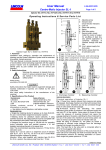
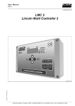
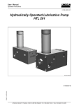
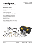
CENTRO-MATIC®
FlowMaster™ Rotary Driven Hydraulic Pump
Models 85487, 86258 & 85470
Series “B”
4.1A-68560-G00
February 2001
Form 403048
Section
- C8
Page
- 272F
CENTRO-MATIC® PUMP, MODELS 85487 & 86258
TABLE OF CONTENTS
Page
Safety...............................................................................................2
Specifications.................................................................................2
Description......................................................................................2
System Operation..........................................................................2
Installing the Pump......................................................................3
Putting Pump into Operation.......................................................3
Maintenance & Repair...................................................................3
Dimensions....................................................................................6
Repair Parts List............................................................................7
Troubleshooting...........................................................................8
SAFETY
Read and carefully observe these operating instructions
before unpacking and operating the pump! The pump must
be operated, maintained and repaired exclusively by
persons familiar with the operating instructions. Local
safety regulations regarding installation, operation and
maintenance must be followed.
Operate this pump only after safety instructions and this
service manual are fully understood.
This symbol indicates a potentially hazardous situation
which, if not avoided, could result in death or serious injury.
Please refer to the 85481 operation manual, section C8,
page 269, series “B”© for all other safety considerations.
PRODUCT SPECIFICATIONS
Supply inlet hydraulic pressure,
maximum, PSIG (bar) Operating working hydraulic
pressure, PSIG (bar) Max. output pressure, PSIG (bar) Hydraulic inlet flow, GPM (l/min) Pump ratio with manifold -
Ambient oper. temp. ºF (ºC) Operating voltage, VDC Hydraulic inlet port, In Tank return port, In Maximum hydraulic
fluid temp., ºF (ºC) Weight, Lbs (Kg) - 86258
- 85487
Container capacity , Lbs (Kg) -
Page Number - 2
3,000 (207)
300 to 450 (21 to 31).
3500 (241)
Up to 7 (27)
9:1 at low inlet pressure
(300 to 350 PSI [21 to 24
bar]) and low inlet flow
(below 2 gpm [7.5 lpm])
Pump ratio approaches
11.0:1 ratio at higher
inlet pressure and flow.
-20 to +150 (-29 to +66)
24
SAE 4
SAE 6
200 (93)
Do not exceed 3,000 PSIG (207 bar) maximum supply inlet
hydraulic pressure or 3500 PSIG (241 bar) maximum outlet
pressure. Exceeding the rated pressures may result in
damage to system components and personal injury.
DESCRIPTION
General Description
The Models 85487 and 86258 are pumping units designed
to operate a Centro-Matic® lubrication system. The units
include a vent valve to relieve the line pressure to recharge
the injectors. FlowMaster™ Rotary Driven Hydraulic Pump
includes pressure reducing valve, flow control valve and
solenoid operated (24 VDC) “On” and “Off” valve.
The FlowMaster pump is fully automatic when used with
Model 85530 Controller and a pressure switch. The
FlowMaster pump is double acting, dispensing lubricant on
both the “Up” and “Down” strokes. This unit is designed to
be used with SL-1, SL-11, SL-32 and SL33 series injectors
or a combination of these.
Model 86258 includes follower plate and low level indicator.
Model 85487 has no follower plate and no low level
indicator.
Appropriate Use
• The pump on this unit is exclusively designed to pump
and dispense lubricants using hydraulic power only.
• The maximum specification ratings should not be
exceeded.
• Any other use not in accordance with instructions will
result in loss of claims for warranty and liability.
SYSTEM OPERATION
Operation with Model 85530 System Controller
When Model 85530 times out, it will initiate a lube cycle.
The solenoid is energized to deliver hydraulic pressure to
the pump and vent valve. Pump begins dispensing
lubricant through injectors to the bearings.
When all bearings have received lubricant, pressure rises
in the system to actuate the pressure switch. When
pressure switch actuates, the control is reset to de-energize
the solenoid valve cutting off hydraulic oil pressure to the
pump and vent valve. Pump stops, pressure vents and
pressure switch de-actuates. Control begins timing toward
next lube event.
93 (41)
83 (37)
60 (27)
4.1A-68560-G00
Form 403048
CENTRO-MATIC® PUMP, MODEL 85487 & 86258
INSTALLING THE PUMP
MAINTENANCE & REPAIR
Place the unit in the approximate location making sure that
electric and hydraulic power connections are accessible.
Mark center locations of the six holes at the bottom of the
reservoir. Then drill six 1/2” (13 mm) holes. The use of
7/16” (11 mm) bolts will offer some flexibility in securing the
reservoir to the equipment.
Lubricant outlet of pump should be connected to system with
suitable hose capable of 3,500 PSI (241 bar) working
pressure. Hydraulic inlet connection should be made with at
least 3/8” (9 mm) I. D. hose capable of at least 3,000 PSI (207
bar) operating pressure. Hydraulic return to tank connection
line should be 3/4” (19 mm) I. D. hose or pipe.
Please refer to the 85481 operation manual, section C8, page
269, series “B” for setting the pump pressure and flow
control.
Low Level Kit (Model 85490)
Low Level Kit is recommended whenever higher viscosity
greases or lower temperatures are encountered and when
an external indicator of lubricant level is desired. The kit is
composed of a follower with wiper and a level indicator gage
located on the cover of the reservoir.
PUTTING PUMP INTO OPERATION
Filling Reservoir
• To bulk fill the reservoir, remove the lower and upper pipe
plugs from the side of the reservoir (see Figure 4). Attach
the appropriatebulk-filling pump to the lower inlet (3/4
NPT). Fill reservoir until grease appears at the top 1/2
NPT vent high level port.Remove the bulk-filling pump.
Replace both pipe plugs.
• To use the reservoir with a five-gallon pail of lubricant
(Model 85487 only), first remove the six bolts that secure
the lid. Remove the entire assembly of lid, pump and vent
valve. Using pipe wrench or vice grips, remove the filler
nipple extension (35) (Figure 4) attached inside the
reservoir at the 3/4 NPT inlet nipple. Insert opened pail of
lubricant and reattach lid and pump assembly.
Note: If five gallon pail lubrication is to be used (for Model
85487 only), then the optional wing screws (38) should be
used in place of the hex bolt (39).
When filling the reservoir, caution should be used as extreme
pressure can cause damage to the reservoir or serious
personal injury.
Form 403048
General Maintenance
• Keep area around pump clean. Clean off filling port area
prior to filling reservoir. Clean area around filler after filling
as lubricants will attract dirt.
• Keep lubricants clean and free of dirt and debris.
• When replacing grease pails be especially careful to
prevent any foreign matter from entering the grease pail or
contaminating the grease, as it adheres to the pump.
In Case of System Malfunction
(See Trouble Shooting Chart Page 8)
• Use the Trouble Shooting Charts to determine where to
look if problems occur.
• See the sections below for replacement and repair of
specific areas of the check valve, vent valve or safety
unloader valve.
• Each part is identified with a number keyed to the
matching part on the illustrated views.
• General recommendations of tools required are also
specified in each step.
• Pay particular attention to the Warning statements to
prevent personal injury and possible damage to pump
components.
Outlet Check Service
(See Figures 1, 2, 7 & 8, Pages 5 & 6)
The pump will not build up sufficient lubricant pressure if the
outlet check (47) is fouled. Foreign material may lodge
beneath the Check Ball (25) or between check disc (21) and
the seat of bushing assembly (22). Sealing surfaces of the
seat must form a perfect seal. Clean parts or replace if
pitted, worn or scored.
1. Turn off and disconnect the hydraulic and electric power
supply to the pump assembly.
2. Standard tools required are a bench mounted vice, a set of
open end wrenches ranging from 7/16” to 1-1/2”, a large
24” (600 mm) adjustable wrench and a smaller 10”
(254 mm) adjustable wrench.
3. Remove bolts and lock washers (52 & 53).
4. Loosen adapter union (48). Set vent valve assembly to
the side.
5. Remove entire outlet check assembly (47) by loosening
adapter (46) from pump outlet.
6. Remove adapter (46) from outlet check assembly (47).
7. Remove outlet connector (26) from bushing (22).
8. Remove ball check seat (23) from outlet connector (26).
9. Inspect all check components (21, 22, 23, 25) for presence
of foreign material, scoring and or other damage, which
may cause internal leakage. Replace components if
damage is found.
4.1A-68560-G00
Page Number - 3
CENTRO-MATIC® PUMP, MODELS 85487 & 86258
10. If foreign material is present, clean components and
reassemble. Be sure to always replace gaskets (20) &
(24) whenever vent valve is disassembled. Reverse the
above procedure to reassemble. Torque check
assembly to 100 ft.-lbs. (13.5 N-M).
Vent Valve Service (See Figures 3, 7 & 8 Pages
5 & 6)
1. Turn off and disconnect the hydraulic and electrical power
supply to the pump assembly.
2. Standard tools required are a bench mounted vice, a set of
open end wrenches ranging from 7/16” to 1-1/2”, a large
24” (600 mm) adjustable wrench and a smaller 10”
(254 mm) adjustable wrench.
3. Remove delivery hose (17). Loosen Adapter Union (48)
and Vent Hose (14).
4. Remove bolts and lock washers (52 & 53). Remove vent
valve.
5. Hold base of vent valve in vice to remove elbows (12 & 15).
Turn vent valve in vice so that vice jaws are gripping flats
machined on base of vent valve.
6. Remove hydraulic cylinder (27). Remove piston and
packing (28) from cylinder. If oil leakage was evident
from side of hydraulic cylinder then replace packing.
7. Remove packing assembly (30). If grease leakage was
evident from side of hydraulic cylinder, then replace
packing assembly.
8. Inspect needle (29) and valve seat (31). If foreign matter is
lodged and is keeping the needle from sealing in valve
seat, clean and inspect for damage. If seat appears
damaged by nicks, grooves or scouring it should be
replaced. Remove valve seat (31) from valve body (33) by
placing a ¾” open end wrench onto the flats and loosening
the seat. The use of an adjustable wrench in place of the
open end wrench may be necessary due to the
accessibility of the seat.
9. Replace the valve seat (31) if damaged. Also be sure to
remove and replace the gasket (32) below the seat.
10. Reassembly is the reverse of the above procedure.
Needle (29) and hydraulic cylinder (27) inside diameter
should be coated with oil or grease to assist in
assembly.
11. Upon reassembly tighten valve seat (31) into body (33)
using 25 ft-lbs. (39 N-M). Tighten hydraulic cylinder (27)
onto valve body (33) using 100 ft-lbs. (135 N-M)
5. Now remove the entire follower assembly from the pump
tube. After removing the follower assembly from the pump
tube wipe off the excess grease which will allow clean
access to the eight bolts that must be removed.
6. Loosen and remove the eight nuts (62) on top of the
follower.
7. Remove the follower weight and the wiper (60).
Replace the wiper with a new one.
8. Reassemble in the reverse of the above procedure
making sure that the long bolts are staggered with the
small ones and that they extend below the follower.
Low Level Indicator (see Figure 4 & 5 Page 5)
If the indicator pin appears to drop prematurely or water is
noticeable on top of the follower then the indicator seal (1)
may be damaged.
1. Remove the eight bolts (39) and lockwashers (40) which
hold the cover on to the reservoir.
2. Inspect the reservoir gasket seal (41) for damage. If
damage is apparent then replace the gasket seal.
3. Remove the entire pump, vent valve and follower assembly
from the reservoir.
4. Remove the retaining ring (56) from the indicator rod
assembly (3).
5. Hold the indicator plug (4) with a wrench while removing
the indicator nut (2).
6. Remove and replace the O-ring (1).
7. Reassemble in the reverse of the above procedure.
Torque the indicator nut (2) to 20 ft.-lbs.
Safety Unloader Valve
(See Figure 1 Page 5)
Safety unloader valve (11) is not serviceable and should be
replaced if malfunction is apparent. Upon reassembly,
tighten to 10 ft-lbs. (13.5 N-M).
The Safety Unloader (11) is set to open at 3,750 to 4,250 PSI
lubricant pressure. If pressure Switch fails to operate and shut
off hydraulic supply to pump, the Safety Unloader will open at
approximately 4,000 PSI to relieve lubricant supply line pressure
(Safety Unloader is preset and cannot be adjusted.)
Bare Pump Assembly (See Figure 4 Page 5)
Please refer to the Operation Manual (C8, Page 269 series)
for the bare pump assembly (34).
Follower (see Figures 4, 5 & 6 Page 5)
If follower wiper appears to be damaged or does not wipe the
sides of the container effectively service may be necessary.
1. Disconnect hydraulic supply from pump.
2. Remove the eight bolts (39) and lock washers (40) which
attach the cover to the reservoir.
3. Lift the entire pump, vent valve, cover assembly and
follower out of the reservoir.
4. Unscrew the low level indicator (3) from the follower
plate (50).
Page Number - 4
4.1A-68560-G00
Form 403048
CENTRO-MATIC® PUMP, MODEL 85487 & 86258
12
13
Connect to Vent
Valve Port
10
22
20
23
21
24
66
26
25
1/4”
NPTF
11
14
15
19
16 18
17
Connect
to Vent Pipe
16
Outlet Check Assembly (47)
Figure 2
Vent Assembly
Figure 1
1/4” NPTF
34
27
28
30
38 (8 Req’d,
Not Shown
39 (8 Req’d)
40 (8 Req’d)
29
41
31
32
33
43
Vent
Port
3/4”
NPTF
3/4”
NPTF
42
Vent Valve (10)
Figure 3
3/4” NPT Male
Connect to Lube System
44
Fill Port
35
Figure 4
56
6
2
64
1
3
5
4
62
(8 Req’d)
60
61
(4 Req’d)
Low Level
Figure 5
Form 403048
Follower Assembly (50)
Figure 6
4.1A-68560-G00
65
(4 Req’d)
59
(8 Req’d)
63
(4 Req’d)
Page Number - 5
CENTRO-MATIC® PUMP, MODELS 85487 & 86258
45
46
47
49
48
17.132”
(435 MM)
9.50”
(242 mm)
Tank Port
SAE 6
Solenoid Valve
Flow Control Valve
Pressure Control
Valve
Figure 7
19.5”
(495 mm)
12
Inlet Port
SAE 4
57
(6
(2
(4
(2
52
Req’d)
53
Req’d)
8
Req’d)
9
Req’d)
7
54
36
(4 Req’d)
58
55
30 15/16”
(786 mm)
51, 59
(4 Req’d)
37
64
A
A
50
15.12”
(384mm)
Model 86258
Model 85487
Figure 9
Figure 8
Page Number - 6
4.1A-68560-G00
Form 403048
CENTRO-MATIC® PUMP, MODEL 85487 & 86258
SERVICE PARTS
Item
No.
1
2
3
4
5
6
7
8
9
10
11
12
13
14
15
16
17
18
19
20
21
22
23
24
25
26
27
28
29
30
31
32
33
Qty.
1
1
1
1
1
1
1
4
2
1
1
1
1
1
1
2
1
1
1
1
1
1
1
1
1
1
1
1
1
1
1
1
1
Description
O-Ring
Indicator Nut
Cable Assembly
Indicator Plug
Washer
Indicator Bracket
Drum Cover
Bolts
Bracket
Vent Valve Assembly
Safety Unloader Ass’y
Elbow
Hydraulic Hose
Vent Hose
Elbow
Nipple
Delivery Hose
Adapter Union
Bushing
Gasket
Pump Check Disc Ass’y
Outlet Check Bushing
Ball Check Seat
Gasket
Steel ball (3/8” Dia.)
Outlet Connector
Hydraulic Cylinder
Piston
Needle
Viton Packing Ass’y
Valve Seat
Check Seat gasket
Valve Body
Model
84050
*249532
16352
249762
249357
48548
361020
241085
50016
270723
84980
*90942
20012
271598
270726
10160
11197
236607
66883
12018
*31029
+*80206
+*90204
*10313
*31001
*66001
+90860
241807
+*244673
*14722
+*239330
*14723
*31047
239336
Item
No.
34
35
36
37
38
39
40
41
42
43
44
45
46
47
48
49
50
51
52
53
54
55
56
57
58
59
60
61
62
63
64
65
66
Qty.
Description
1
1
4
1
8
8
8
1
1
1
1
1
1
1
1
1
1
4
6
2
1
1
1
1
1
12
1
4
8
4
1
4
1
Bare Pump Assembly
Extension Tube
Hex Nut
Vent pipe
Wing Screws (not shown)
Bolt
Lock Washer
Gasket
Container Assembly
Pipe Plug, Vent
Pipe Plug, Fill
Vent Fitting
Adapter
Outlet Check Assembly
Adapter Union
Reducer Nipple
Follower Assembly
Screw
Lock Washer
Bolt
Gasket
Nut
Retaining Ring
Elbow
Gasket
Lockwasher
Wiper (Nitrile)
Carriage Bolt (Short)
Nut
Bolt (Long)
O-Ring
Spacer
Adapter Elbow
Model
84050
85481
249356
51026
67420
252727
50015
66220
*249355
242765
67117
67224
249354
12213
81938
66645
14727
85489
50169
66246
50034
*31010
12538
*68888
249533
33152
66186
*249331
249332
51304
50084
270720
249833
271599
* Suggested service replacement component
+ Sold as an assembly. Individual parts not available.
* Suggested service replacement components
Form 403048
4.1A-68560-G00
Page Number - 7
CENTRO-MATIC® PUMP, MODELS 85487 & 86258
MODELS 85487 & 86258 TROUBLESHOOTING
CONDITION
Pump does not operate.
POSSIBLE CAUSE
No hydraulic power to pump.
No pressure on gauge:
- Closed Supply line shut off valve.
- No power to solenoid valve.
- Faulty Solenoid.
- Pressure Reducing Valve is set too low.
- Insufficient Hydraulic Fluid supply.
Pressure is shown on gauge on pump
manifold.
- Closed fluid outlet line.
- Flow Control Valve is fully closed.
- Pump is stalled due to grease
backpressure.
Pump is seized or damaged.
Pump runs excessively.
Pump tube malfunction.
Outlet check damage or contamination.
Vent valve damage or contamination.
Pump speeds up or runs
erratically.
Pump runs, but output is low.
System component leaking.
Vent valve not recieving proper pressure to
keep it closed.
Injector bypassing.
Low level of grease or reservoir
is empty.
Follower plate is stuck and separated
from grease.
Pump piston or checks are worn.
Insufficient hydraulic fluid supply.
Inlet pressure too low.
Faulty inlet or discharge check valve in pump.
Lubricant leaking from safety
unloader valve.
Lubricant leaking from weep
hole in vent valve.
Americas:
One Lincoln Way
St. Louis, MO 63120-1578
USA
Phone +1.314.679.4200
Fax +1.800.424.5359
Page Number - 8
Pressure of system set too high.
Safety unloader damaged or contaminated.
Vent valve lubricant seal damaged.
Europe/Africa:
Heinrich-Hertz-Str 2-8
D-69183 Walldorf
Germany
Phone +49.6227.33.0
Fax +49.6227.33.259
Asia/Pacific:
25 Int’l Business Park
#01-65 German Centre
Singapore 609916
Phone +65.562.7960
Fax +65.562.9967
4.1A-68560-G00
CORRECTIVE ACTION
Turn on or connect hydraulic supply to
pump.
Open shut-off valve.
Correct electrical fault.
Replace solenoid.
Reset Pressure Reducing Valve.
Check hydraulic supply for proper
pressure and flow.
Check outlet line and clear
obstructions.
Readjust flow control valve to 1 turn open.
Check vent valve in system.
Dismantle the pump and repair
defective or seized component. See
pump service page.
Refer to pump service page.
Repair check or remove contamination.
Repair vent valve or remove
contamination.
Repair leaks.
Orifice fitting plugged.
Repair injectors.
Refill reservoir.
Check follower plate and container
for damage.
Refer to pump service sheet.
Check hydraulic supply and adjust
flow.
Increase pressure at pressure control
valve.
Replace faulty components. See pump
service page.
Adjust pressure switch setting.
Replace safety unloader.
Replace lubricant seal.
© Copyright 1999
Printed in USA
Web site:
www.lincolnindustrial.com
Form 403048