1
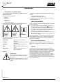
User Manual LMC 2 9.3EN-98003-A09 LMC 2 Lincoln Multi Controller 2 Subject to modifications B-LMC2 -000 a09 LINCOLN GmbH • Postfach 1263 • D-69183 Walldorf • Tel +49 (6227) 33-0 • Fax +49 (6227) 33-259 User Manual LMC 2 9.3EN-98003-A09 This User Manual was compiled on behalf of - the manufacturer - by Lincoln GmbH EdiDoc GmbH Heinrich-Hertz-Str. 2-8 Erzberger Str. 8 D-69169 Walldorf D-68753 Waghäusel All rights reserved. Any duplication of this User Manual, in its entirety or in part, by whatever means is prohibited without the prior consent in writing of Lincoln GmbH. Subject to modifications without prior notification. Subject to modifications © 2010 by Phone: +49 (6227) 33-0 Fax: +49 (6227) 33-259 E-Mail: [email protected] Page 2 of 44 LINCOLN GmbH • Postfach 1263 • D-69183 Walldorf • Tel +49 (6227) 33-0 • Fax +49 (6227) 33-259 User Manual LMC 2 9.3EN-98003-A09 Table of contents Page Introduction Explanation of symbols used ............... ..................... ......... User’s responsibility ...... ...................... ..................... ......... Environmental protection ..................... ..................... ......... Service ..... ..................... ...................... ..................... ......... 4 4 4 4 Safety instructions Intended use .................. ...................... ..................... ......... Improper use ... .............. ...................... ..................... ......... Exclusion of liability .. ...................... ..................... ......... General safety instructions .................. ..................... ......... Regulation for prevention of accidents ..................... ......... Operation, maintenance and repair ..... ..................... ......... Disposal .... ..................... ...................... ..................... ......... 5 5 5 5 5 5 5 Page Technical data ........... ...................... ..................... ............ 9 Replacement parts .... ...................... ..................... ............ 9 EC declaration of conformity ......... ..................... ............ 9 Fault messages and system status messages .. .......... 10 Description Application ..................... ...................... ..................... ......... 6 MENU Reference list ..... ...................... ..................... ......... 7 Parameters, Survey DIP-switch combinations ................... ..................... .......... 11 PMA lubrication systems … ........... ..................... .......... 12 Progressive systems … ................. ..................... .......... 16 Progressive systems for railroad lubrication .... .......... 20 - Particularities of railroad lubrication ................................... 23 Two-line systems … . ...................... ..................... .......... 26 Installation Connection .................... ...................... ..................... ......... 8 Mounting channels for fastening .......... ..................... ....... 42 Centro-Matic® systems … .............. ..................... .......... 30 COBRA chain-lubrication systems … ................ .......... 34 Subject to modifications Spray-lubrication systems … ......... ..................... .......... 38 … Quicktour Operating mode Connect ion Operation - Commissioning - Parameter presetting - Selecting the lubrication system Operation - Adapting the parameters Display panel in the operating mode Page 3 of 44 LINCOLN GmbH • Postfach 1263 • D-69183 Walldorf • Tel +49 (6227) 33-0 • Fax +49 (6227) 33-259 User Manual LMC 2 9.3EN-98003-A09 Introduction Explanation of Symbols Used The following description standards are used in this manual: Safety Instructions Structure of safety instructions: Pictogram Signal word Danger text - Danger note - How to avoid danger The following pictograms are used in this manual and are combined with the corresponding signal words: 101 3A94 4273a 00 - ATTENTION - CAUTION - ATTENTION - CAUTION - WARNING - WARNING 600 1a02 - NOTE - IMPORTANT The signal words give the seriousness of danger if the following text is not observed: ATTENTION CAUTION WARNING NOTE IMPORTANT refers to faults or damages on machines. refers to bad damages and possible injuries. refers to possible dangerous injuries. indicates improved operation of the device. indicates special operating features of the device. Example: ATTENTION! User's Responsibility To ensure the safe operation of the unit, the user is responsible for the following: 1. The pump / system shall be operated only for the intended use (see next chapter "Safety Instructions") and its design shall neither be modified nor transformed. 2. The pump / system shall be operated only if it is in a proper functioning condition and if it is operated in accordance with the maintenance requirements. 3. The operating personnel must be familiar with this Owner Manual and the safety instructions mentioned within and observe these carefully. The correct installation and connection of tubes and hoses, if not specified by Lincoln GmbH, is the user's responsibility. Lincoln GmbH will gladly assist you wit h any questions pertaining to the inst allation. Environmental Protection Waste (e.g. used oil, detergents, lubricants) must be disposed of in accordance with relevant environmental regulations. Service The personnel responsible for the handling of the pump / system must be suitably qualified. If required, Lincoln GmbH offers you full service in the form of advice, on-site installation assistance, training, etc. We will be pleased to inform you about our possibilities to support you purposef ully. In the event of inquiries pertaining to maintenance, repairs and spare parts, we require model specific data to enable us to clearly identify the components of your pump / system. Therefore, always indicate the part, model and series number of your pump / system. Subject to modifications 1 013A94 When making use of other than the tested spare parts, serious damage may affect your device. Therefore, for the operation of your device always use original parts made by Lincoln GmbH. Furthermore, you will find the following text symbols in this manual: Listing of applicable statements - Subpoint of applicable stat ements 1. Determination of the number or sequence of contents  Procedural instruction Page 4 of 44 LINCOLN GmbH • Postfach 1263 • D-69183 Walldorf • Tel +49 (6227) 33-0 • Fax +49 (6227) 33-259 User Manual LMC 2 9.3EN-98003-A09 Safety instructions Intended use - Use the LMC2 multi controller solely for controlling or monitoring Lincoln centralized lubrication-systems in stationary industrial plants. Accident prevention rules Comply wit h the rules applicable in the country of use. Do not operate - using non-authorized spare parts - with power supplies (VAC/VDC) that do not comply with the electrical design of the LMC2 Improper use Any kind of use of the LMC2 not explicitly denoted in this user information as intended use is considered improper use. If the LMC2 is used or operated in deviation from the intended use, all claims for compensation and all liability cease t o exist. NOTE 600 1a02 Misappropriate use, e.g. through disregard of the safety instructions or through improper installation of the LMC2 invalidates all legal claims against Lincoln GmbH for any personal injury or damage to materials. Exclusion of liability Operation, maintenance and repair LMC2 safety devices: - do not modify them or make them inoperative - do not remove them from the lubrication system - reattach them before commissioning or start-up Mount the LMC2 between 0. 4 and 2.0 m above the access level wit h cable glants towards bottom (wallmounting). Keep the LMC2 multi controller away from heat sources. Comply wit h the operating temperature. Replace a defective LMC2 in its entirety (see “Spare parts“ chapter, page 9). The manufacturer of the LMC2 is not liable for damage caused by CAUTION! - non-environmentally compatible disposal - unauthorized modifications to the system parts - use of spare parts not authorized by Lincoln - commissioning and start-up in defective condition - erroneous program selection by the user 4273 a00 General safety instructions The multi controller LMC2 - is designed based on state of the art technology - can be assembled safe-to-operate Improper use can lead to damage due to under- or overlubrication of bearings and bearing points. Independent alterat ions or modifications to an installed system may only be carried out af ter prior consultation with the manufacturer or its cont ract partner. The LMC2 may only be installed by qualified personnel that are familiar with its operat ing instructions. The connection (N/L/PE) to the power supply must be carried out according to VDE 0100 and VDE 0160. Install a safety device and interrupt facility to disconnect the LMC2. Disconnect the mains connection before starting installation and service work. Make sure to provide a safeguard to prevent unintentional reclosing of the disconnecting device. After completion of wiring, individual cores must be secured against dislocation. WARNING! WARNING! Dangerous residual voltages! 4273 a00 Even during a standstill the motor or valve may be applied wit h voltage. Non-compliance with the safety instructions, such as contact with electrically conducting parts with an open LMC2 or improper handling the same can endanger life. The device could overheat if the technical data specif ied in the t echnical data sheet are exceeded. This can destroy the LMC2 and can impair the electrical safety. 427 3a00 Disposal Subject to modifications Dispose of the LMC2 in an environmentally friendly way, according to the relevant and legal regulations. Page 5 of 44 LINCOLN GmbH • Postfach 1263 • D-69183 Walldorf • Tel +49 (6227) 33-0 • Fax +49 (6227) 33-259 User Manual LMC 2 9.3EN-98003-A09 Description Application The LMC 2 multi controller is used to cont rol and monitor the following stationary Lincoln lubrication systems. - PMA systems - Progressive systems - Railroad lubrication - Two-line systems - Centro-Matic ® syst ems - COBRA chain-lubrication systems - Spray systems It combines the flexibility of freely programmable controllers with the cost eff ectiveness of pre-programmed control p.c.b.’s. Functionality and menu display in the LMC2 are set to specifically matching parameters depending on the lubrication system selected. Parameter name (t = time, c = counter): - t – MO ................ .............. (Monitoring) Monitoring time - t – PS ................. ...................... .................. Pause time - t – rn .................. ...................... ... (run) Lubrication time - t – od .................. ................ (off delay) Switch-off delay - t – cl ................... .............. (clean) Nipple cleaning time - c – rn ......... (run) Lubrication / revolution / stroke count - c – PS ................ ............. Number of pause revolut ions - c – PS (Railroad lubrication) .... ........... Number of axes - c – bl .................. ............. (Bolts) Number of chain links The lubrication system and presettings for its parameters can be set (UP & DOWN keys, pos. 3, Fig. 1) using the DIP-switches (SW1, SW2, SW3 & SW4, pos. 12, Fig. 2) You can make additional parameter modifications with the operating panel on the LMC2 membrane keypad in the “Setup mode“ (see the “Operating“ section in the respective lubrication system. All settings and count values are saved every 30 minutes in the LMC2 EEPROM, which means they are not lost even if the mains supply fails. B-LM C2-020a0 9 Fig. 1 LMC2 membrane keypad 14-digit 7-segment display 2LED status display - Power on (white) - Readiness for operation (green) / Malfunction (red) - Pump is running (green) - Low-level signal (yellow) 3Operating panel - left MENU / RUN - right ENTER / RESET - up (UP) short + 1 count value long + high speed - down (DOWN) short - 1 count value long – high speed 4Information on handling 6608m0 6 12 - DIP-switch (from left: SW1, SW2, SW3, SW4) The LMC2 control p.c.b. (VDC) Subject to modifications Fig. 2 Page 6 of 44 LINCOLN GmbH • Postfach 1263 • D-69183 Walldorf • Tel +49 (6227) 33-0 • Fax +49 (6227) 33-259 User Manual LMC 2 9.3EN-98003-A09 Description, continued MENU Reference list Navigation Through key(s) ENTER + MENU Centralized LMC2 lubrication system Display menu item Parameter Factory setting PMA systems Count value Throug h UP or DOWN key ENTER 1 c – rn Number of lubrication cycles 1 to 9999 lubrication cycles ±1 stroke ENTER 1 c – PS Number of pause cycl es 1 to 9999 pause cycles ±1 pause cycle 10 c – bl Number of chain links 1 to 9999 chain links ±1 chain link ENTER ENTER Jumps back to the first parameter RUN Acknowl edgment of the modifications carried out & return to the operating mode ENTER + MENU Progressive systems ±1 minute ± 1 axis ENTER 10 min. 10 t – PS c – PS Pause time 1 min. to 99 h. and 59 min. 1 to 9999 axes ENTER 1 c – rn 1) Number of metering device cycles 1 to 99 metering device cycles ±1 cycl e 2 min. t – rn 1) Lubrication time 1 min. to 99 min. and 59 sec. ±1 second Monitoring time 1 min. to 99 min. and 59 sec. ±1 second ENTER 2 Min. t – MO 1) ENTER Jumps back to the first parameter RUN Acknowl edgement of the modifications carried out & return to the operating mode ENTER + MENU Two-line systems ENTER 12 min. t – MO Monitoring time 1 min. to 99 min. and 59 sec. ±1 second ENTER 10 min. t – PS Pause time 1 min. to 99 h. and 59 min. ENTER Jumps back to the first parameter RUN Acknowl edgement of the modifications carried out & return to the operating mode ENTER + MENU Centro-Matic systems ±1 minute ® ENTER 2 min. t – MO Monitoring time 1 min. to 99 min. and 59 sec. ±1 second ENTER 10 min. t – PS Pause time 1 min. to 99 h. and 59 min. ±1 minute ENTER 10 sec. t – od Switch-off del ay time 1 sec. to 99 sec. ±1 second ENTER RUN Jumps back to the first parameter Acknowl edgement of the modifications carried out & return to the operating mode ENTER + MENU COBRA chain lubrication systems 1 sec. to 99 sec. ±1 second ENTER 10 sec. t – cl Cleaning time per nipple ENTER 1 c – rn Number of lubrication cycles 1 to 9999 lubrication cycles ±1 lubrication cycle ENTER 1 c – PS Number of pause cycl es 1 to 9999 pause cycles ±1 pause cycle ENTER 10 c – bl Number of chain links 1 to 9999 chain links ±1 chain link ENTER RUN Jumps back to the first parameter Acknowl edgement of the modifications carried out & return to the operating mode ENTER + MENU Spray systems ENTER ENTER 10 Min. ENTER 1 min. to 99 h. and 59 min. c – rn Number of metering device cycles 1 to 99 metering device cycles ±1 cycl e 2 min. t – rn 1) Lubrication time 1 min. to 99 min. and 59 sec. ±1 second 2 Min. t – MO Monitoring time 1 min. to 99 min. and 59 sec. ±1 second 10 sec. t – od Re-spraying-time 1 sec. to 99 sec. 1) ENTER Jumps back to the first parameter RUN Acknowl edgement of the modifications carried out & return to the operating mode 1) ±1 minute Pause time 1) 1 t – PS ENTER Subject to modifications Section ±1 second Are displayed or hidden depending on the parameter presetting (see “DIP-switch c ombinations“, page 11) in the set-up mode (see “Quicktour“, pages 16, 20 and 38). Page 7 of 44 LINCOLN GmbH • Postfach 1263 • D-69183 Walldorf • Tel +49 (6227) 33-0 • Fax +49 (6227) 33-259 User Manual LMC 2 9.3EN-98003-A09 Installation Connection 5- 6- 6609m0 6 Fig. 3 78- The terminals for signal inputs (pos. 5), for the ACTUATOR lines (pos. 6) and for the mains supply (pos. 7) are located on the control p.c.b. (Fig. 3). Signal input - for 3-wire initiators up to 24 V (PNP) - for 2-wire initiators, residual voltage < 5 V Control output (ACTUATOR) - 4 relay outputs - 1 electronic output Voltage supply (24 VDC / 10 A or 230 VAC / 3 A) Program interface (RJ 45) LMC2 electrical connecti ons Route the LMC2 connection cables t hrough the cable glands (item 9 and 10) on the bottom of the housing. Possible tensile forces on the cables have to be relieved from outside of the housing. Fasten on the rear of the housing using the mounting channels (pos. 11) with the cable glands towards bottom (wall-mounting). Cable glands: 9Voltage supply (M16 screwed connection) 10 - Control inputs and outputs (for 0.5 mm² cable) 6607m0 7 Subject to modifications Fig. 4 661 0b06 Fig. 5 11 - Mounting channels for fastening (dimensions see page 36) Housi ng AProgramming BBUS interface, option (field bus plug) C - Controller D - Display I1 - I8 Signal input connection Q1-Q5 Control output (ACTUATOR) connection Connection diagram Page 8 of 44 LINCOLN GmbH • Postfach 1263 • D-69183 Walldorf • Tel +49 (6227) 33-0 • Fax +49 (6227) 33-259 User Manual LMC 2 9.3EN-98003-A09 Technical data LMC2 multi controller Dimensions (L x W x H) ....... ..................... 200 x 120 x 90 mm Display ........... ..................... ............ 4-fold 7-segment display Operating temperature ........ ...................... ...... - 10 to + 70 °C Storage temperature ........... ...................... ...... - 40 to + 85 °C AC input Inputs: Number .......... .................... 8, short-circuit proof, non-floating Cutoff f requency .................. ...................... .................. 100 Hz DC input Outputs: Number .......... ..................... ...................... ...................... ..... 5 - …….4 relay outputs NO contact s 6A, 0-240 VAC/ VDC - overload protected ............ ...................... 1 electronic output .. ...................... ..................... ...... 24 VDC/10A or 230 VAC/3A Reverse polarity protecti on: Operating voltage inputs are protected against reverse polarity Residual ripple at operating voltage: .. ...................... ..................... ..... ±5% according to DIN 41755 Input voltage ....... .................. 230 VAC ±10% ; 50/60 Hz ±5% Fast fuse ............. ..................... .................. 4 A/250 V internal Input voltage ....... ..................... ...................... .. 24 VDC ±20% Slow f use ............ ..................... ...................... ................. 10 A Safety DIN EN 60204 Protection class .. ..................... ...................... .............. Class I EMC Interference suppression VDE 0875 T 11, EN 55011 Class A Noise out put ....... ..................... .... according to EN 61000-6-4 Immunity to electrical noise ..... .... according to EN 61000-6-2 NOTE NOTE If the internal fuses need to be replaced, use only the original type. 6001 a02 The noise output complies with the requirements for the industrial sector. If used in residential areas, this can lead to interaction under certain circumst ances. 600 1a02 Protection and monitoring: Current limitation ................. ....... Sustained short-circuit proof Overload protected ............. ...................... ...................... . yes Idle protected . ..................... ...................... ...................... . yes Power failure backup time ... ................... > 15 ms at 230 VAC Protection class ................... ...................... ..................... IP 54 Replacement parts LMC2 multi controller Type 24 VDC . ........................................... ......... 236-10567-5 Type 230 VAC .... ..................... ...................... .... 236-10567-6 Declaration of Conformity according to EMC-directive 2004/108/EC We hereby declare that the multi controller Lincoln Multi Controller LMC2 in the design we have delivered complies with the regulations in the above-referenced directive. Subject to modifications The following harmonized standards were applied: DIN EN 60204 DIN EN 61000-6-4 DIN EN 61000-6-2 Safety Test Emitted Interference Interference Immunity Walldorf, 05-May-06, Dr. Ing. Z. Paluncic Page 9 of 44 LINCOLN GmbH • Postfach 1263 • D-69183 Walldorf • Tel +49 (6227) 33-0 • Fax +49 (6227) 33-259 User Manual LMC 2 Fault messages 1) and system status messages 2) ERROR CODE CAUSE 1) Signal error from actuator 9.3EN-98003-A09 REMEDY  Check the output connection and correct if applicable.  Repair the short circuit if applicable. E-OL  Check the functioning of the actuator and replace if applicable. 1) E-IN  Check the sensor connection and correct if applicable.  Repair the short circuit if applicable. 1) Signal error from sensor E-MS OFF through motor protecting switch  I f applicable, prevent overload on motor.  Repair the short circuit if applicable.  Replace incorrect / def ective motor if applicable. 1) 1) TYPE Incorrect lubricating program set  Carry out the correct DIP-switch setting to select t he version (see t able, page 11). Pressure switch to monitor the pressure relief did not drop, counter pressure could still be applied  Check the pressure line system for counter pressure and manually bleed it if necessary. E-PD  Check the pressure switch for correct operation and replace if applicable.  Check the final-pressure monitor frame size and replace if applicable.  Check the pressure relief valve and replace if applicable. 1) Set pause time is shorter than the  I ncrease the pause time. lubricating time As the pause time is also restarted at the start of the lubricating t ime, the following setting value applies: Pause time > Lubricating time Signal error from met ering device  Check the pressure line system for blockage and repair it if necessary. E-D 1) E-OP 1) E-CD 1)  Replace the piston detector or proximity switch on the metering device and replace if applicable. Pressure at the pressure switch of  Check the pressure line system for blockage and repair it. the pump is too high Wrong moving direction of conveyor chain E-FC 1)  Swivel COBRA back into the operating position.  Correct moving direction of the conveyor chain. Stroke monitor report s: Valve stroke not carried out  Check the pressure line system and valve. Monit oring time exceeded  Check for cause in the pressure line system (e.g. pipe fracture) and repair as necessary.  Remove blockage or replace the valve.  Check signal line for interruption and replace the connection if necessary. T-OUT Subject to modifications  I f applicable, adapt the monitoring time if the pressure line system is free from defects. 1) E-FL 1) E-C 1) E-AP Filling time monitoring exceeded  Check filler pump and filling syst em. COBRA misaligned mechanically from operating position  Realign COBRA. Supply air pressure too low  Check compressed air supply.  Readjust pressure regulator if necessary. 2) LL Low-level control  Fill reservoir. 2) HL High-level control  Stop reservoir filling. Page 10 of 44 LINCOLN GmbH • Postfach 1263 • D-69183 Walldorf • Tel +49 (6227) 33-0 • Fax +49 (6227) 33-259 User Manual LMC 2 9.3EN-98003-A09 Parameters, Survey DIP-switch combinations Scheme DIP switch SW 1 SW 2 SW 3 SW 4 0 0 0 0 Lubrication System / function PMA Versions Parameter presetting 0 no stroke monitoring 1 with stroke monitoring 0 no metering device and without cycle counter 1 with one metering device and without cycle counter 2 with one metering device and with cycle counter 3 with two metering devices and without cycle counter 4 with two metering devices and with cycle counter 5 - 1 circuit-…, with metering device without cycle counter 6 661c06 1 0 0 0 Progressive 6 665c06 - … Railroad lubrication 6 - 1 circuit-…, with metering device with cycle counter 7 - 2 circuit-…, with metering device without cycle counter 8 - 2 circuit-…, with metering device with cycle counter 9 - 3 circuit-…, with metering device without cycle counter 10 0 1 0 0 Two-line 6 663c06 1 1 0 0 Centro-Matic® - 3 circuit-…, with metering device with cycle counter 0 EMU without monitored metering device 1) 1 EMU with monitored metering device 1) 2 SU without monitored metering device 2) 3 SU with monitored metering device 2) 4 3ZWV without monitored metering device 3) 5 3ZWV with monitored distributor 3) 0 with one pressure switch 1 with two pressure switches 0 standard setting 0 no metering device and no cycle counter, clock-pulsed 1 with metering device and no cycle counter, clock-pulsed 2 with metering device and cycle counter, clock-pulsed 3 no metering device, no cycle counter, not clock-pulsed 4 with metering device and cycle counter, not clock-pulsed 5 with metering device and cycle counter, not clock-pulsed 6 667c06 0 0 1 0 COBRA 6 662c06 1 0 1 0 Spray lubricating system 6 666c06 0 1 1 0 Test mode 1 1 1 0 Configuration mode Subject to modifications 6 664c06 666 8b06 1) EMU – electronic change-over control 2) SU – pressure-controlled change-over control 3) 3ZWV - 3/2-way valve Page 11 of 44 LINCOLN GmbH • Postfach 1263 • D-69183 Walldorf • Tel +49 (6227) 33-0 • Fax +49 (6227) 33-259 User Manual LMC 2 9.3EN-98003-A09 PMA lubrication systems Subject to modifications Quicktour Page 12 of 44 LINCOLN GmbH • Postfach 1263 • D-69183 Walldorf • Tel +49 (6227) 33-0 • Fax +49 (6227) 33-259 User Manual LMC 2 9.3EN-98003-A09 PMA lubrication systems, continued Operating mode The following parameters are controlled or monitored for PMA lubricating syst ems via the standard LMC 1 programming: Variable: - Cycle-dependent lubrication - Number of chain pause-cycles - Number of chain links Connection 661 7b06 Fig. 6 Signal input connection 1) A - External contact E - Stroke monitoring 1) B - Chain sensor F - Reserve C – Low-level signal G - Additional lubrication D – High-level signal H - Remote reset Time stop respectively lubrication stop 661 2b06 Fig. 7 Control output (ACTUATOR) connection Q2 - System (ready for operation) PE - Protective earth conductor Q3 - Lubrication active L+ - Power supply + Q4 - Reserve M - Power supply – Subject to modifications Q1 - Pump Q5 - Reserve Page 13 of 44 LINCOLN GmbH • Postfach 1263 • D-69183 Walldorf • Tel +49 (6227) 33-0 • Fax +49 (6227) 33-259 User Manual LMC 2 9.3EN-98003-A09 PMA lubrication systems, continued Operation – Commissioning Parameter presetting, continuation  Select from the following versions to set the parameter presettings in your PMA lubrication system: - no stroke monitoring ...................... ......................... ....... 0 - with stroke monitoring ............... ................. .................... 1 NOTE 6 001a0 2 6 613m06 Fig. 8 Operating panel a - „UP“ key b - „DOWN“key The version number setting (0 - 1) is shown in the LMC2 display and is made using the UP & DOWN keys on the operating panel (see pos. a & b, Fig. 8).  Complete your selection (0 - 1) with the ENTER key. I f you do not acknowledge your selection with ENTER, the standard value of “0“ is automatically set.  Wait unt il in the display panel of the LMC 2 the text changes from „init“ (Fig. B) to „Set“ (Fig. C) or „Addr“ (Fig. A): NOTE “RESET“ as halt function: 6001a 02 1) You can int errupt the running lubrication 1) time by pressing the “RESET“ key (> 2 sec.). The next pause cycle starts from the beginning. B-LMC2 -050 f09 Fig. B Display „init“ B-L MC2-050c09 Fig. C Display „SEt“ or, if applicable, externally via switch H (see Fig. 6) 6001a 02 NOTE Selecting the lubrication system „RUN“ to trigger additional lubrications:  First swit ch SW1 to SW3 to “0-0-0“ (OFF-OFF-OFF). You can int errupt the running pause cycle by pressing the “RUN“ key (> 2 sec.). The lubricating time starts from the beginning. Then set the right-hand DIP switch (SW4) to ON: NOTE 6001a 02 6661b06 As soon as you press the "UP" key (pos. a, Fig. 9) outside of the configuration mode, the actual rest of the expired pause time (Fig. D) or lubricating time (Fig. E) is shown in the display. Fig. 10 DIP switch: PMA lubrication systems - settings After that, switch SW4 back to OFF: 6660b06 Fig. 11 Parameter presetting  Set the DIP switches 12 (see view Fig. 2) as shown in Fig. 9: 1-1-1-0: SW1 ON SW2 ON SW3 ON SW4 OFF Fig. 9 DIP switch: PMA lubrication systems – operating mode The standard settings to control your PMA lubrication system are now complete and the system is ready for operation (Fig. D). Please refer t o page 15 f or possible parameter adaptations. 6668b 06 DIP switch – configuration mode The display panel of the LMC 2 shows the text „Addr“: B-L MC2-050b 09 Fig. A Subject to modifications Display „Addr“  In the case of a field bus connect ion, set the system-related address code 0001 to 0255 by means of the UP and DOWN keys (see Fig. 8).  Complete your selection wit h the ENTER key (Fig. 8). Page 14 of 44 LINCOLN GmbH • Postfach 1263 • D-69183 Walldorf • Tel +49 (6227) 33-0 • Fax +49 (6227) 33-259 User Manual LMC 2 9.3EN-98003-A09 PMA lubrication systems, continued Operation, continued Adapting the parameters  Press and hold the “ENTER“ key and then press “MENU“ to open the configuration mode. You can modify the count value of every parameter using the “UP“ and “DOWN“ keys as below: - Press briefly ……………………….…. .. ± 1 count value - Keep pressed ……………………………. ± High speed Presettings 0 or 1: (see table on page 11) Stroke monitoring The stroke monitor checks the functioning of the linear solenoid. Menu i tem * c–rn *, Number of lubricating cycl es (Cycle-dependent lubrication) The number of lubricating cycles determines how often the chain must run through until it is completely lubricated.  Press the “UP“ or “D OWN“ key to configure the number of lubricating cycles. - Section 1 to 9999 lubricat ing cycles - Count value 1 lubricating cycle  Conclude the selection with the “ENTER“ key. Continue wit h the * c–PS * menu item. Menu i tem * c–PS *, Number of pause cycles The number of pause cycles sets the number of nonlubricated chain cycles that must transpire bet ween two lubrication processes.  Press the “UP“ or “D OWN“ key to configure the number of pause cycles. - Section 1 to 9999 pause cycles - Count value 1 pause cycle Menu item * c–bl *, Number of chain links The number of chain links determines the number of lubrication strokes for one lubricating cycle.  Press the “UP“ or “DOWN“ key to configure the number of chain links. - Section 1 to 9999 chain links - Count value 1 chain link  Conclude the selection with the “ENTER“ key.  Press the “RUN“ key (> 2 sec.) to incorporate the changes made to all menu items. Otherwise, after 30 seconds the program reverts back to the operating mode.  If you want to change a menu item again, press t he “ENTER“ key. You will once more automatically arrive at the start of the configuration mode. Display panel in the operating mode  Conclude the selection with the “ENTER“ key. Continue wit h the * c–bl * menu item. During the pause time the display panel of the LMC 2 shows the text „WAit“: B-LMC2 -050 d09 Fig. D Display „WAit“ Fig. E Display „Lub“ During the lubricating time the display panel of the LMC 2 shows the text „Lub“: Subject to modifications B-LMC2 -050 e09 Page 15 of 44 LINCOLN GmbH • Postfach 1263 • D-69183 Walldorf • Tel +49 (6227) 33-0 • Fax +49 (6227) 33-259 User Manual LMC 2 9.3EN-98003-A09 Progressive systems Subject to modifications Quicktour Page 16 of 44 LINCOLN GmbH • Postfach 1263 • D-69183 Walldorf • Tel +49 (6227) 33-0 • Fax +49 (6227) 33-259 User Manual LMC 2 9.3EN-98003-A09 Progressive systems, continued Operating mode The following parameters are controlled or monitored for progressive systems via the standard LMC 1 programming: Variable: - Pause time - Time or cycle-dependent lubrication - Monit oring time Fixed: - Filling time monitoring 15 min. Connection 661 1b06 Fig. 12 Signal input connection A - External contact 1) E – Metering device sensor 1) B – Metering device sensor F - Motor protection C – Low-level signal G - Additional lubrication D – High-level signal H - Remote reset Time stop respectively lubrication stop 661 2b06 Q3 - Filling L+ - Power supply + Q4 - Reserved M - Power supply – Subject to modifications Fig. 13 Control output (ACTUATOR) connection Q1 - Pump Q2 - System (ready for operation) Q5 - Reserve PE - Protective earth conductor Page 17 of 44 LINCOLN GmbH • Postfach 1263 • D-69183 Walldorf • Tel +49 (6227) 33-0 • Fax +49 (6227) 33-259 User Manual LMC 2 9.3EN-98003-A09 Progressive systems, continued Operation – Commissioning Parameter presetting, continuation  Select from the following versions to set the parameter presettings in your progressive system: - no metering device and no cycle counter ………… …….. 0 - wit h one metering device and no cycle counter ….…….. 1 - with one met ering device and cycle counter .................. 2 - with two metering devices, no cycle counter ………....... 3 - wit h two metering devices and cycle counter ................. 4 NOTE 6 613m06 Fig. 15 Operating panel a - „UP“ key 6 001a0 2  Complete your selection (0 - 4) with the ENTER key (Fig. 15). I f you do not acknowledge your selection with ENTER, the standard value of “0“ is automatically set. b - „DOWN“ key NOTE “RESET“ as hold function: 6001a 02 1) The version number setting (0 - 4) is shown in the LMC2 display and is made using the UP & DOWN keys on the operating panel (see pos. a & b, Fig. 15). You can int errupt the running lubrication 1) time by pressing the „RESET“ key (> 2 sec.). The pause time starts from the beginning.  Wait unt il in the display panel of the LMC 2 the text changes from „init“ (Fig. B) to „Set“ (Fig. C) or „Addr“ (Fig. A): or, if applicable, externally via switch H (see Fig. 12) NOTE B-LMC2 -050 f09 „RUN“ to trigger additional lubrications: 6001a 02 You can interrupt the running pause time by pressing the “RUN“ key (> 2 sec.). The lubricating time starts from the beginning. NOTE 6001a 02 Fig. B Then set the right-hand DIP switch (SW4) to ON: 6665b06 Parameter presetting DIP switch: progressive systems - settings After that, switch SW4 back to OFF:  Set the DIP switches 12 (see view Fig. 2) as shown in Fig. 16: 6665 c06 Fig. 18 6668b 06 Display „SEt“  First swit ch SW1 to SW3 to “1-0-0“ (ON-OFF-OFF). Fig. 17 Fig. 16 B-L MC2-050c09 Fig. C Selecting the lubrication system As soon as you press the "UP" key (pos. a, Fig. 15) outside of the configuration mode, the actual rest of the expired pause time (Fig. D) or lubricating time (Fig. E) is shown in the display. 1-1-1-0: SW1 ON SW2 ON SW3 ON SW4 OFF Display „init“ DIP switch: progressive systems – ready for operation The standard settings to control your progressive system are now complete and the system is ready for operation (Fig. D). DIP switch – configuration mode Please refer t o page 19 f or possible parameter adaptations. The display panel of the LMC 2 shows the text „Addr“: B-L MC2-050b 09 Subject to modifications Fig. A Display „Addr“  In the case of a field bus connect ion, set the system-related address code 0001 to 0255 by means of the UP and DOWN keys (see Fig. 15).  Complete your selection wit h the ENTER key (Fig. 15). Page 18 of 44 LINCOLN GmbH • Postfach 1263 • D-69183 Walldorf • Tel +49 (6227) 33-0 • Fax +49 (6227) 33-259 User Manual LMC 2 9.3EN-98003-A09 Progressive systems, continued Operation, continued Adapting the parameters  Press and hold the “ENTER“ key and then press “MENU“ to open the configuration mode. You can modify the count value of every parameter using the “UP“ and “DOWN“ keys as below: - Press briefly ……………….…….….…. ± 1 count value - Keep pressed ……………………………. ± High speed Presettings 1, 2, 3, 4, 5, 6, 7, 8, 9 or 10: (see table on page 11) Menu i tem * t–MO *, monitoring time (Lubrication with monitored metering device) Setting the monitoring time determines the time interval in which at least one metering device cycle has to have ended before a f ault indication.  Press the “UP“ or “D OWN“ key to configure the monitoring time. - Section 1 sec. to 99 min. and 59 sec. - Count value 1 sec  Conclude the selection with the “ENTER“ key. Continue wit h the * t–PS * menu item. Presettings 0, 1, 3, 5, 7 or 9: (see table on page 11) Menu i tem * t–PS *, pause time The pause time determines the time interval that must expire between two lubrication sequences.  Press the “UP“ or “D OWN“ key to configure the pause time. - Section 1 min. to 99 h and 59 min. - Count value 1 min. Presettings 2, 4, 6, 8 or 10: (see table on page 11) Menu item * c–rn *, number of metering device cycles (cycle-dependent lubrication) The number of metering device cycles determines how often all metering pistons in the monitored metering device must convey their amount s of lubricant to provide all lubrication points in the progressive system with sufficient lubricant .  Press the “UP“ or “DOWN“ key to configure the number of distributor cycles. - Section 0 to 99 distributor cycles - Count value 1 Distributor cycle 6001 a02 NOTE As the pause time is also restarted at the start of the lubricating time, the following set ting value applies: Pause time > Lubricating t ime I f the ratio is reversed, the fault indication * E-PD * appears in the LMC 1 display (see page 10).  Conclude the selection with the “ENTER“ key.  Press the “RUN“ key (> 2 sec.), to incorporate the changes made to all menu items. Otherwise, after 30 seconds the program reverts back to the operating mode (run).  If you want to change a menu item again, press the “ENTER“ key. You will once more automatically arrive at the start of the configuration mode.  Conclude the selection with the “ENTER“ key. Continue wit h the * t–rn * or * c–rn * menu items. Presettings 0, 1, 3, 5, 7 or 9: (see table on page 11) Menu i tem * t–rn *, Lubricating time (time-dependent lubrication) The lubricating time determines how long a lubrication sequence takes to provide all the lubrication points in the progressive system with sufficient lubricant.  Press the “UP“ or “D OWN“ key to configure the lubrication time. - Section 1 sec. to 99 min. and 59 sec. - Count value 1 sec Subject to modifications  Conclude the selection with the “ENTER“ key. Display panel in the operating mode During the pause time the display panel of the LMC 2 shows the text „WAit“: B-LMC2 -050 d09 Fig. D During the lubricating time the display panel of the LMC 2 shows the text „Lub“: Display „WAit“ B-LMC2 -050 e09 Fig. E Display „Lub“ Page 19 of 44 LINCOLN GmbH • Postfach 1263 • D-69183 Walldorf • Tel +49 (6227) 33-0 • Fax +49 (6227) 33-259 User Manual LMC 2 9.3EN-98003-A09 Progressive systems for Railroad lubrication Subject to modifications Quicktour Page 20 of 44 LINCOLN GmbH • Postfach 1263 • D-69183 Walldorf • Tel +49 (6227) 33-0 • Fax +49 (6227) 33-259 User Manual LMC 2 9.3EN-98003-A09 Progressive systems for railroad lubrication, continued Operating mode The following parameters are controlled or monitored for progressive systems via the standard LMC 1 programming: Variable: - Pause time (c-PS) - Time or cycle-dependent lubrication - Monit oring time Fixed: - Filling time monitoring 15 min. Connection B-LMC 2-04 0a09 Fig. 12a Signal input connection 1) A - External contact E - Sensor, rail 2 1) B - Metering device sensor F - Motor protection C - Low-level control G - Additional lubrication D - Sensor, rail 1 H - Sensor, rail 3 Counting or lubricating stop e.g. via rain sensor; then operation continues with stored times or counting status (EEPROM) 661 2b06 Q3 - Val ve circuit rail 1 L+ - Power supply + Q4 - Valve circuit rail 2 M - Power supply – Subject to modifications Fig. 13a Control output (ACTUATOR) connection Q1 - Pump Q2 - System (ready for operation) Q5 - Valve circuit rail 3 PE - Protective earth conductor Page 21 of 44 LINCOLN GmbH • Postfach 1263 • D-69183 Walldorf • Tel +49 (6227) 33-0 • Fax +49 (6227) 33-259 User Manual LMC 2 9.3EN-98003-A09 Progressive systems for railroad lubrication, continued Connection, continued Railroad Lubrication B-LMC 2-05 0a09 Fig. 14a Connections – Signal input & control output (actuator) A1 - Rail 1 S1 - Sensor 1 V1 - Valve 1 A2 - Rail 2 S2 - Sensor 2 V2 - Valve 2 A3 - Rail 3 S3 - Sensor 3 V3 - Valve 3 B - Reservoir LL - Low-level control D - Metering device M - Motor protection GSM – Data transfer standard (as an option) P - Pump I1-I8 - Signal input (see Fig. 12a) Subject to modifications Particularities of railroad lubrication Q1-Q5 - Controller output, actuator (see Fig. 13a) Mode of operation On up to 3 tracks the rail sensors D, E & H (Fig. 12a) detect the number of passing axes. The pause time of the cent ralized lubrication system results from the count ed measurand of axes (1 to 9999) determined by the rail sensors. The stop contact A (Fig. 12a, e. g. rain sensor) allows to int errupt counting of the axes (pause time) as well as to int errupt the lubricating time. Later, operation continues from the point of interruption. Page 22 of 44 LINCOLN GmbH • Postfach 1263 • D-69183 Walldorf • Tel +49 (6227) 33-0 • Fax +49 (6227) 33-259 User Manual LMC 2 9.3EN-98003-A09 Progressive systems for Railroad lubrication, continued Operation – Commissioning Parameter presetting, continuation  Select from the following versions to set the parameter presettings in your progressive system for railroad lubricat ion: - 1 circuit-…, wit h met. dev. without cycle counter ............ 5 - 1 circuit-…, with met. dev. with cycle counter …… ......... 6 - 2 circuit-…, with met. dev. without cycle counter............ 7 - 2 circuit-…, with met . dev. with cycle counter ................ 8 - 3 circuit-…, with met . dev. without cycle counter ........... 9 - 3 circuit-…, with met . dev. with cycle counter .............. 10 NOTE 6 613m06 Fig. 15a Bedienfeld a - „UP“ key b - „DOWN“ key 6 001a0 2 NOTE “RESET“ as hold function: 6001a 02 You can int errupt the running lubrication time by pressing the „RESET“ key (> 2 sec.). The pause time starts from the beginning. The version number setting (5 - 10) is shown in the LMC2 display and is made using the UP & DOWN keys on the operat ing panel (see pos. a & b, Fig. 15a).  Complete your selection (5 - 10) with the ENTER key (Fig. 15a). I f you do not acknowledge your selection with ENTER, the standard value of “5“ is automatically set.  Wait unt il in the display panel of the LMC 2 the text changes from „init“ (Fig. B) to „Set“ (Fig. C) or „Addr“ (Fig. A): NOTE „RUN“ to trigger additional lubrications: 6001a 02 Fig. B Display „init“ B-L MC2-050c09 Fig. C Display „SEt“ Selecting the lubrication system NOTE 6001a 02 B-LMC2 -050 f09 You can interrupt the running pause time by pressing the “RUN“ key (> 2 sec.). The lubricating time starts from the beginning. As soon as you press the "UP" key (pos. a, Fig. 15a) outside of the configuration mode, the actual rest of the expired pause time (Fig. D) or lubricating time (Fig. E) is shown in the display.  First swit ch SW1 to SW3 to “1-0-0“ (ON-OFF-OFF). Then set the right-hand DIP switch (SW4) to ON: 6665b06 Fig. 17a DIP switch: progressive systems - settings Parameter presetting  Set the DIP switches 12 (see view Fig. 2) as shown in Fig. 16a: 1-1-1-0: SW1 ON SW2 ON SW3 ON SW4 OFF 6665 c06 Fig. 18a DIP switch: progressive systems – ready for operation 6668b 06 Fig. 16a DIP switch – configuration mode The display panel of the LMC 2 shows the text „Addr“: The standard settings to control your progressive system are now complete and the system is ready for operation (Fig. D). Please refer t o page 24 f or possible parameter adaptations. B-L MC2-050b 09 Fig. A Subject to modifications After that, switch SW4 back to OFF: Display „Addr“  In the case of a field bus connect ion, set the system-related address code 0001 to 0255 by means of the UP and DOWN keys (see Fig. 15a).  Complete your selection wit h the ENTER key (Fig. 15a). Page 23 of 44 LINCOLN GmbH • Postfach 1263 • D-69183 Walldorf • Tel +49 (6227) 33-0 • Fax +49 (6227) 33-259 User Manual LMC 2 9.3EN-98003-A09 Progressive systems for railroad lubrication, continued Operation – Adapting the parameters  Press and hold the “ENTER“ key and then press “MENU“ to open the configuration mode. You can modify the count value of every parameter using the “UP“ and “DOWN“ keys as below: - Press briefly ……………….…….….…. ± 1 count value - Keep pressed ……………………………. ± High speed Presetting 5, 6, 7, 8, 9 or 10: (see table on page 11) Menu i tem * t–MO *, monitoring time (Lubrication with monitored metering device) Setting the monitoring time determines the time interval in which at least one metering device cycle has to have ended before a f ault indication.  Press the “UP“ or “D OWN“ key to configure the monitoring time. - Section 1 sec. to 99 min. and 59 sec. - Count value 1 sec  Conclude the selection with the “ENTER“ key. Continue wit h the * t–rn * or * c–rn * menu item. Presetting 5, 7 or 9: (see table on page 11) Menu i tem * t–rn *, Lubricating time (time-dependent lubrication) The lubricating time determines how long a lubrication sequence takes to provide all the lubrication points in the progressive system with sufficient lubricant.  Press the “UP“ or “D OWN“ key to configure the lubrication time. - Section 1 sec. to 99 min. and 59 sec. - Count value 1 sec  Conclude the selection with the “ENTER“ key. Presetting 6, 8 or 10: (see table on page 11) Menu item * c–rn *, number of metering device cycles (cycle-dependent lubrication) The number of metering device cycles determines how often all metering pistons in the monitored metering device must convey their amounts of lubricant to provide all lubrication points in the progressive system with suff icient lubricant.  Press the “UP“ or “DOWN“ key to configure the number of distributor cycles. - Section 0 to 99 distributor cycles - Count value 1 Distributor cycle  Conclude the selection with the “ENTER“ key.  Continue with the * c–PS * menu item. Presetting 5, 6, 7, 8, 9 or 10: (see table on page 11) Menu item * t–PS *, pause time The number of axes counted determines the pause time that has to lapse until the next lubrication cycle can take place.  Press the “UP“ or “DOWN“ key to configure the pause time. - Section 1 to 9999 axes - Count value 1 axis  Conclude the selection with the “ENTER“ key.  Press the “RUN“ key (> 2 sec.), to incorporate the changes made to all menu items. Otherwise, after 30 seconds the program reverts back to the operating mode (run).  If you want to change a menu item again, press t he “ENTER“ key. You will once more automatically arrive at the start of the configuration mode.  Continue wit h the * c–PS * menu item. Display panel in the operating mode During the pause time the display panel of the LMC 2 shows the text „WAit“: B-LMC2 -050 d09 Fig. D During the lubricating time the display panel of the LMC 2 shows the text „Lub“: B-LMC2 -050 e09 Fig. E Subject to modifications Display „WAit“ Display „Lub“ Page 24 of 44 LINCOLN GmbH • Postfach 1263 • D-69183 Walldorf • Tel +49 (6227) 33-0 • Fax +49 (6227) 33-259 User Manual LMC 2 9.3EN-98003-A09 Subject to modifications Note: Page 25 of 44 LINCOLN GmbH • Postfach 1263 • D-69183 Walldorf • Tel +49 (6227) 33-0 • Fax +49 (6227) 33-259 User Manual LMC 2 9.3EN-98003-A09 Two-line systems Subject to modifications Quicktour Page 26 of 44 LINCOLN GmbH • Postfach 1263 • D-69183 Walldorf • Tel +49 (6227) 33-0 • Fax +49 (6227) 33-259 User Manual LMC 2 9.3EN-98003-A09 Two-line systems, continued Operating mode The following parameters are controlled or monitored via the standard LMC 1 programming for two-line systems: Variable: - Pause time - Monit oring time Fixed: - Filling time monitoring 15 min. Connection 661 5b06 Fig. 19 Signal input connection 1) A - External contact B – Metering device sensor E – Pressure switch, pump F - Motor protection 1) C – Low-level signal G – End-of-line pressure switch 1 (DU1) D – High-level signal H – End-of line pressure switch 2 Time stop respectively lubrication stop 661 2b06 Q3 - Filling L+ - Power supply + Q4 - Change-over device 1 M - Power supply – Subject to modifications Fig. 20 Control output (ACTUATOR) connection Q1 - Pump Q2 - System (ready for operation) Q5 - Change-over device 2 PE - Protective earth conductor Page 27 of 44 LINCOLN GmbH • Postfach 1263 • D-69183 Walldorf • Tel +49 (6227) 33-0 • Fax +49 (6227) 33-259 User Manual LMC 2 9.3EN-98003-A09 Two-line systems, continued Operation – Commissioning Parameter presetting, continuation 6 613m06 Fig. 21 Operating panel a - „UP“ key 6001a 02 b - „DOWN“ key NOTE NOTE “RESET“ as hold function: The version number setting (0 - 5) is shown in the LMC2 display and is made using the UP & DOWN keys on the operating panel (see pos. a & b, Fig. 21). You can int errupt the running lubrication time by pressing the “RESET“ key (> 2 sec.). The pause time starts from the beginning. NOTE „RUN“ to trigger additional lubrications: 6001a 02  Select from the following versions to set the parameter presettings in your two-line plant: - electronic change-over without metering device monitoring ..…..………………... 0 - electronic change-over with metering device monitoring ………..…… ………….. 1 - pressure controlled change-over without metering device monitoring ……..………………. 2 - pressure controlled change-over with metering device monitoring ..……………................. 3 - 3/2-way valve without metering device monitoring ……..………………. 4 - 3/2-way valve with metering device monitoring …………………… ……. 5 You can interrupt the running pause time by pressing the “RUN“ key (> 2 sec.). The lubricating time starts from the beginning. 6 001a0 2  Complete your selection (0 - 5) with the ENTER key (Fig. 21). I f you do not acknowledge your selection with ENTER, the standard value of “0“ is automatically set.  Wait unt il in the display panel of the LMC 2 the text changes from „init“ (Fig. B) to „Set“ (Fig. C) or „Addr“ (Fig. A): NOTE 6001a 02 As soon as you press the "UP" key (pos. a, Fig. 21) outside of the configuration mode, the actual rest of the expired pause time (Fig. D) or lubricating time (Fig. E) is shown in the display. B-LMC2 -050 f09 Fig. B B-L MC2-050c09 Fig. C Display „SEt“ Selecting the lubrication system  First swit ch SW1 to SW3 to “0-1-0“ (OFF-ON-OFF). Parameter presetting  Set the DIP switches 12 (see view Fig. 2) as shown in Fig. 22: 1-1-1-0: SW1 ON SW2 ON SW3 ON SW4 OFF Fig. 22 Display „init“ Then set the right-hand DIP switch (SW4) to ON: 6663b06 Fig. 23 6668b 06 DIP switch: Two-line systems - settings After that, switch SW4 back to OFF: DIP switch – configuration mode 6663 c06 The display panel of the LMC 2 shows the text „Addr“: Fig. 24 B-L MC2-050b 09 Subject to modifications Fig. A Display „Addr“  In the case of a field bus connect ion, set the system-related address code 0001 to 0255 by means of the UP and DOWN keys (see Fig. 21). DIP switch: Two-line systems – ready for operation The standard settings to control your two-line system are now complete and the system is ready for operation (Fig. D). Please refer t o page 29 f or possible parameter adaptations.  Complete your selection wit h the ENTER key (Fig. 21). Page 28 of 44 LINCOLN GmbH • Postfach 1263 • D-69183 Walldorf • Tel +49 (6227) 33-0 • Fax +49 (6227) 33-259 User Manual LMC 2 9.3EN-98003-A09 Two-line systems, continued Operation, continued Adapting the parameters  Press and hold the “ENTER“ key and then press “MENU“ to open the configuration mode. You can modify the count value of every parameter using the “UP“ and “DOWN“ keys as below: - Press briefly ……………………….…. .. ± 1 count value - Keep pressed ……………………………. ± High speed Presettings 0, 1, 2, 3, 4 or 5:: (see table on page 11) Menu i tem * t–MO *, monitoring time (Lubrication with monitored metering device) Setting the monitoring time determines the time interval in which the corresponding final pressure monitor has to be acknowledged before a fault indication. If a monitored metering device is present , a signal change has to be completed before the end of a lubrication cycle (full pulse). Presettings 0, 1, 2, 3, 4 or 5: (see table on page 11) Menu item * t–PS *, pause time  Press the “UP“ or “D OWN“ key to configure the monitoring time. - Section 1 sec. to 99 min. and 59 sec. - Count value 1 sec  Conclude the selection with the “ENTER“ key.  Conclude the selection with the “ENTER“ key. Continue wit h the * t–PS * menu item. NOTE 600 1a02 The pause time determines the time interval that must expire between two lubrication sequences.  Press the “UP“ or “DOWN“ key to configure the pause time. - Section 1 min. to 99 h and 59 min. - Count value 1 min.  Press the “RUN“ key (> 2 sec.), to incorporate the changes made to all menu items. Otherwise, after 30 seconds the program reverts back to the operating mode.  If you want to change a menu item again, press t he “ENTER“ key. You will once more automatically arrive at the start of the configuration mode. As the pause time is also restarted at the start of the lubrication time, the following setting value applies: Pause time > Lubrication time If the ratio is reversed, the f ault indication * E-PD * appears in the LMC 1 display (see page 10). Display panel in the operating mode During the pause time the display panel of the LMC 2 shows the text „WAit“: B-LMC2 -050 d09 Fig. D Display „WAit“ Fig. E Display „Lub“ During the lubricating time the display panel of the LMC 2 shows the text „Lub“: Subject to modifications B-LMC2 -050 e09 Page 29 of 44 LINCOLN GmbH • Postfach 1263 • D-69183 Walldorf • Tel +49 (6227) 33-0 • Fax +49 (6227) 33-259 User Manual LMC 2 Centro-Matic® systems 9.3EN-98003-A09 Subject to modifications Quicktour Page 30 of 44 LINCOLN GmbH • Postfach 1263 • D-69183 Walldorf • Tel +49 (6227) 33-0 • Fax +49 (6227) 33-259 User Manual LMC 2 Centro-Matic® systems, continued 9.3EN-98003-A09 Operating mode The following parameters are controlled or monitored via the standard LMC 1 programming for Cent ro-Matic ® systems: Variable: - Pause time - Monit oring time - Switch-off delay time Connection 661 4b06 Fig. 25 Signal input connection 1) A - External contact E – Pressure switch 2 1) B – Pressure switch 1 F - Reserve C – Low-level signal G - Additional lubrication D – High-level signal H - Remote reset Time stop respectively lubrication stop 661 2b06 Fig. 26 Control output (ACTUATOR) connection Q2 - System (ready for operation) PE - Protective earth conductor Q3 - Lubrication active L+ - Power supply + Q4 - Relief M - Power supply – Subject to modifications Q1 - Pump Q5 - Reserve Page 31 of 44 LINCOLN GmbH • Postfach 1263 • D-69183 Walldorf • Tel +49 (6227) 33-0 • Fax +49 (6227) 33-259 User Manual LMC 2 9.3EN-98003-A09 Centro-Matic® systems, continued Operation – Commissioning Parameter presetting, continuation  Select from the following versions to set the parameter presettings in your Centro-Matic® system: - with one pressure switch …………..……………………... 0 - with two pressure switches …………..……… …………... 1 NOTE 6 001a0 2 6 613m06 Fig. 27 Operating panel a - „UP“ key b - „DOWN“ key “RESET“ as hold function: 1)  Complete your selection (0 - 1) with the ENTER key (Fig. 27). I f you do not acknowledge your selection with ENTER, the standard value of “0“ is automatically set.  Wait unt il in the display panel of the LMC 2 the text changes from „init“ (Fig. B) to „Set“ (Fig. C) or „Addr“ (Fig. A): NOTE 6001a 02 The version number setting (0 - 1) is shown in the LMC2 display and is made using the UP & DOWN keys on the operating panel (see pos. a & b, Fig. 27). You can int errupt the running lubrication 1) time by pressing the “RESET“ key (> 2 sec.). The pause time starts from the beginning. B-LMC2 -050 f09 or, if applicable, externally via switch H (see Fig. 25) Fig. B Display „init“ B-L MC2-050c09 Fig. C Display „SEt“ NOTE 6001a 02 „RUN“ to trigger additional lubrications: Selecting the lubrication system You can interrupt the running pause time by pressing the “RUN“ key (> 2 sec.). The lubricating time starts from the beginning.  First swit ch SW1 to SW1 to SW3 to “1-1-0“ (ON-ON-OFF). NOTE 6001a 02 Then set the right-hand DIP switch (SW4) to ON: As soon as you press the "UP" key (pos. a, Fig. 27) outside of the configuration mode, the actual rest of the expired pause time (Fig. D) or lubricating time (Fig. E) is shown in the display. 6667b06 Fig. 29 After that, switch SW4 back to OFF: Parameter presetting 6667 c06  Set the DIP switches 12 (see view Fig. 2) as shown in Fig. 28: 1-1-1-0: SW1 ON SW2 ON SW3 ON SW4 OFF Fig. 28 6668b 06 Fig. 30 DIP switch: Centro-Mati c® systems – operating mode The standard settings to control your Centro-Matic ® system are now complete and the system is ready for operation (Fig. D). Please refer t o page 33 f or possible parameter adaptations. DIP switch – configuration mode The display panel of the LMC 2 shows the text „Addr“: B-L MC2-050b 09 Fig. A Subject to modifications DIP switch: Centro-Mati c® systems - settings Display „Addr“  In the case of a field bus connect ion, set the system-related address code 0001 to 0255 by means of the UP and DOWN keys (see Fig. 27).  Complete your selection wit h the ENTER key (Fig. 27). Page 32 of 44 LINCOLN GmbH • Postfach 1263 • D-69183 Walldorf • Tel +49 (6227) 33-0 • Fax +49 (6227) 33-259 User Manual LMC 2 9.3EN-98003-A09 Centro-Matic® systems, continued Operation, continued Adapting the parameters  Press and hold the „ENTER“ key and then press „MENU“ to open the configuration mode. You can modify the count value of every parameter using the „UP“ and „DOWN“ keys as below: - Press briefly ……………………….…. .. ± 1 count value - Keep pressed ……………………………. ± High speed Presettings 0 or 1: (see table on page 11) Menu i tem * t–MO *, monitoring time Setting the monitoring time determines the time interval in which an acknowledgement needs to be made before a fault indication appears f or the pressure switch(es). Menu item * t–od *, hold time The hold time determines t he time interval, how long the relief valve will remain closed through the switch-off delay after lubrication has finished.  Press the „UP“ or „D OWN“ key to configure the monitoring time. - Section 1 sec. to 99 min. and 59 sec. - Count value 1 sec  Press the „UP“ or „DOWN“ key to configure the respraying time. - Section 1 sec. t o 99 sec. - Count value 1 sec  Conclude the selection with the „ENTER“ key.  Conclude the selection with the „ENTER“ key. Continue wit h the * t–PS * menu item. Menu i tem * t–PS *, pause time The pause time determines the time interval that must expire between two lubrication sequences.  Press the „UP“ or „D OWN“ key to configure the pause time. - Section 1 min. to 99 h and 59 min. - Count value 1 min.  Press the „RUN“ key (> 2 sec.), to incorporate the changes made to all menu items. Otherwise, after 30 seconds the program reverts back to the operating mode.  If you want to change a menu item again, press the „ENTER“ key. You will once more automatically arrive at the start of the configuration mode.  Conclude the selection with the „ENTER“ key. Continue wit h the * t–od * menu item. Display panel in the operating mode NOTE 600 1a02 As the pause time is also restarted at the start of the lubrication time, the following setting value applies: Pause time > Lubrication time If the ratio is reversed, the f ault indication * E-PD * appears in the LMC 1 display (see page 10). During the pause time the display panel of the LMC 2 shows the text „WAit“: B-LMC2 -050 d09 Fig. D Display „WAit“ Fig. E Display „Lub“ Fig. D Display „HoLd“ During the lubricating time the display panel of the LMC 2 shows the text „Lub“: B-LMC2 -050 e09 During the hold time the display panel of the LMC 2 shows the text „HoLd“: Subject to modifications B-LMC2 -050 g09 Page 33 of 44 LINCOLN GmbH • Postfach 1263 • D-69183 Walldorf • Tel +49 (6227) 33-0 • Fax +49 (6227) 33-259 User Manual LMC 2 9.3EN-98003-A09 COBRA chain-lubrication systems Subject to modifications Quicktour Page 34 of 44 LINCOLN GmbH • Postfach 1263 • D-69183 Walldorf • Tel +49 (6227) 33-0 • Fax +49 (6227) 33-259 User Manual LMC 2 9.3EN-98003-A09 COBRA chain-lubrication systems, continued Operating mode The following parameters are controlled or monitored for COBRA chain-lubrication systems via the standard LMC 1 programming: Variable: - Nipple cleaning time - Cycle-dependent lubrication - Number of pause cycles - Number of chain links Fixed: - Filling time monitoring 1 min. Connection 661 8b06 Fig. 31 Signal input connection A - External contact, chain forwards E - Air pressure switch B - Chain sensor F - Malfunction, right side C - Low-level signal G - Malfunction, left side D - Lubricant pressure H - Locking 661 2b06 Q3 - Clean L+ - Power supply + Q4 - COBRA 1X-1 M - Power supply – Subject to modifications Fig. 32 Control output (ACTUATOR) connection Q1 - Pump Q2 - System (ready for operation) Q5 - COBRA 1X-2 PE - Protective earth conductor Page 35 of 44 LINCOLN GmbH • Postfach 1263 • D-69183 Walldorf • Tel +49 (6227) 33-0 • Fax +49 (6227) 33-259 User Manual LMC 2 9.3EN-98003-A09 COBRA chain-lubrication systems, continued Operation – Commissioning Parameter presetting, continuation NOTE No parameter presettings can be set for COBRA chain-lubrication systems. The standard setting “0“ applies. 6 001a0 2  Complete your selection (0) with the ENTER key (Fig. 33). I f you do not acknowledge your selection with ENTER, the standard value of “0“ is automatically set. 6 613m06 Fig. 33 Operating panel a - „UP“-Taste  Wait unt il in the display panel of the LMC 2 the text changes from „init“ (Fig. B) to „Set“ (Fig. C) or „Addr“ (Fig. A): b - „DOWN“-Taste NOTE B-LMC2 -050 f09 “RESET“ as halt function: 6001a 02 Fig. B You can int errupt the running lubrication time by pressing the “RESET“ key (> 2 sec.). The next pause cycle starts from the beginning. Display „init“ B-L MC2-050c09 Fig. C Display „SEt“ Selecting the lubrication system  First swit ch SW1 to SW3 to “0-0-1“ (OFF-OFF-ON). NOTE „RUN“ to trigger additional lubrications: 6001a 02 Then set the right-hand DIP switch (SW4) to ON: You can int errupt the running pause cycle by pressing the “RUN“ key (> 2 sec.). The lubricating time starts immediately. 6662b06 Fig. 35 DIP switch: COBRA chain-lubrication systems - settings NOTE 6001a 02 As soon as you press the "UP" key (pos. a, Fig. 33) outside of the configuration mode, the actual rest of the expired pause time (Fig. D) or lubricating time (Fig. E) is shown in the display. After that, switch SW4 back to OFF: 6662 c06 Fig. 36 Parameter presetting  Set the DIP switches 12 (see view Fig. 2) as shown in Fig. 34: 1-1-1-0: SW1 ON SW2 ON SW3 ON SW4 OFF Fig. 34 The standard settings to control your COBRA chain-lubrication system are now complete and the system is ready for operation (Fig. D ). Please refer t o page 37 f or possible parameter adaptations. 6668b 06 DIP switch – configuration mode The display panel of the LMC 2 shows the text „Addr“: B-L MC2-050b 09 Fig. A Subject to modifications DIP switch: COBRA chain-lubrication systems – operati ng mode Display „Addr“  In the case of a field bus connect ion, set the system-related address code 0001 to 0255 by means of the UP and DOWN keys (see Fig. 33).  Complete your selection wit h the ENTER key (Fig. 33). Page 36 of 44 LINCOLN GmbH • Postfach 1263 • D-69183 Walldorf • Tel +49 (6227) 33-0 • Fax +49 (6227) 33-259 User Manual LMC 2 9.3EN-98003-A09 COBRA chain-lubrication systems, continued Operation, continued Adapting the parameters  Press and hold the “ENTER“ key and then press “MENU“ to open the configuration mode. You can modify the count value of every parameter using the “UP“ and “DOWN“ keys as below: - Press briefly ……………………….…. .. ± 1 count value - Keep pressed ……………………………. ± High speed Menu i tem * t–cl *, Nipple cleaning time Menu item * c–PS *, Number of pause cycles The nipple cleaning time determines the time interval of the duration of the cleaning of a lubrication nipple. The number of pause cycles sets the number of nonlubricated chain cycles that must transpire between two lubrication processes.  Press the “UP“ or “D OWN“ key to configure the nipple cleaning time. - Section 1 sec. to 99 sec. - Count value 1 sec  Conclude the selection with the “ENTER“ key.  Press the “UP“ or “DOWN“ key to configure the number of pause cycles. - Section 1 to 9999 pause cycles - Count value 1 pause cycle  Continue wit h menu item * c–rn *.  Conclude the selection with the “ENTER“ key. Menu i tem * c–rn *, Lubricating cycles (Cycle-dependent lubrication) The number of lubricating cycles determines how often the chain must run through until it is completely lubricated. Continue with the * c–bl * menu item. Menu item * c–bl *, Number of chain links The number of chain links determines the number of lubrication strokes for one chain cycle.  Press the “UP“ or “D OWN“ key to configure the number of lubricating cycles. - Section 1 to 9999 lubricat ing cycles - Count value 1 lubricating cycle  Press the “UP“ or “DOWN“ key to configure the number of chain links. - Section 1 to 9999 chain links - Count value 1 chain link  Conclude the selection with the “ENTER“ key.  Conclude the selection with the “ENTER“ key. Continue wit h the * c–PS * menu item.  Press the “RUN“ key (> 2 sec.) to incorporate the changes made to all menu items. Otherwise, after 30 seconds the program reverts back to the operating mode.  If you want to change a menu item again, press the “ENTER“ key. You will once more automatically arrive at the start of the configuration mode. Display panel in the operating mode During the pause time the display panel of the LMC 2 shows the text „WAit“: B-LMC2 -050 d09 Fig. D Subject to modifications During the lubricating time the display panel of the LMC 2 shows the text „Lub“: Display „WAit“ B-LMC2 -050 e09 Fig. E Display „Lub“ Page 37 of 44 LINCOLN GmbH • Postfach 1263 • D-69183 Walldorf • Tel +49 (6227) 33-0 • Fax +49 (6227) 33-259 User Manual LMC 2 9.3EN-98003-A09 Spray lubrication system Subject to modifications Quicktour Page 38 of 44 LINCOLN GmbH • Postfach 1263 • D-69183 Walldorf • Tel +49 (6227) 33-0 • Fax +49 (6227) 33-259 User Manual LMC 2 9.3EN-98003-A09 Spray lubrication system, continued Operating mode The following parameters are controlled or monitored via the standard LMC 1 programming for spray lubricat ion systems: Variable: - Pause time - Time or cycle-dependent lubrication - Monit oring time - Re-spraying time Fixed: - Filling time monitoring 15 min. Connection 661 6b06 Fig. 37 Signal input connection A - External contact 1) E - Compressed air switch 1) B – Metering device sensor F - Motor protection C – Low-level signal G - Additional lubrication D – High-level signal H - Remote reset Time stop respectively lubrication stop 661 2b06 Q3 - Filling L+ - Power supply + Q4 - Air valve M - Power supply – Subject to modifications Fig. 38 Control output (ACTUATOR) connection Q1 - Pump Q2 - System (ready for operation) Q5 - Reserve PE - Protective earth conductor Page 39 of 44 LINCOLN GmbH • Postfach 1263 • D-69183 Walldorf • Tel +49 (6227) 33-0 • Fax +49 (6227) 33-259 User Manual LMC 2 9.3EN-98003-A09 Spray lubrication systems, continued Operation – Commissioning Parameter presetting, continuation  Select from the following versions to set the parameter presettings in your spray lubrication system: - no metering device, no cycle counter, clock-pulsed .…... 0 - with metering device, no cycle counter, clock-pulsed …. 1 - with metering device and cycle counter, clock-pulsed ... 2 - no metering dev., no cycle counter, not clock-pulsed …. 3 - with metering dev., no cycle counter, not clock-pulsed .. 4 - with metering dev. and cycle counter, not clock-pulsed 5 NOTE 6 613m06 Fig. 39 Operating panel a - „UP“ key 6 001a0 2 b - „DOWN“ key NOTE “RESET“ as hold function: 6001a 02 1) You can int errupt the running lubrication 1) time by pressing the “RESET“ key (> 2 sec.). The pause time starts from the beginning. The version number setting (0 - 5) is shown in the LMC2 display and is made using the UP & DOWN keys on the operating panel (see pos. a & b, Fig. 39).  Complete your selection (0 - 5) with the ENTER key (Fig. 39). I f you do not acknowledge your selection with ENTER, the standard value of “0“ is automatically set.  Wait unt il in the display panel of the LMC 2 the text changes from „init“ (Fig. B) to „Set“ (Fig. C) or „Addr“ (Fig. A): or, if applicable, externally via switch H (see Fig. 37) NOTE „RUN“ to trigger additional lubrications: 6001a 02 You can interrupt the running pause time by pressing the “RUN“ key (> 2 sec.). The lubricating time starts from the beginning. NOTE 6001a 02 As soon as you press the "UP" key (pos. a, Fig. 39) outside of the configuration mode, the actual rest of the expired pause time (Fig. D) or lubricating time (Fig. E) is shown in the display. B-LMC2 -050 f09 Fig. B Display „init“ B-L MC2-050c09 Fig. C Display „SEt“ Selecting the lubrication system  First swit ch SW1 to SW3 to “1-0-1“ (ON-OFF-ON). Then set the right-hand DIP switch (SW4) to ON: 6666b06 Fig. 41 DIP switch: Spray lubrication systems - settings Parameter presetting  Set the DIP switches 12 (see view Fig. 2) as shown in Fig. 40: 6666 c06 1-1-1-0: SW1 ON SW2 ON SW3 ON SW4 OFF Fig. 40 Fig. 42 6668b 06 DIP switch – configuration mode DIP switch: Spray lubrication systems – ready for operation The standard settings to control your spray lubrication system are now complete and the system is ready for operation (Fig. D). Please refer t o page 41 f or possible parameter adaptations. The display panel of the LMC 2 shows the text „Addr“: B-L MC2-050b 09 Fig. A Subject to modifications After that, switch SW4 back to OFF: Display „Addr“  In the case of a field bus connect ion, set the system-related address code 0001 to 0255 by means of the UP and DOWN keys (see Fig. 39).  Complete your selection wit h the ENTER key (Fig. 39). Page 40 of 44 LINCOLN GmbH • Postfach 1263 • D-69183 Walldorf • Tel +49 (6227) 33-0 • Fax +49 (6227) 33-259 User Manual LMC 2 9.3EN-98003-A09 Spray lubrication systems, continued Operation, continued Adapting the parameters  Press and hold the “ENTER“ key and then press “MENU“ to open the configuration mode. You can modify the count value of every parameter using the “UP“ and “DOWN“ keys as below: - Press briefly ……………………….…. .. ± 1 count value - Keep pressed ……………………………. ± High speed Presettings 1 or 2: (see table on page 11) Menu i tem * t–MO *, monitoring time (Lubrication with monitored metering device) Setting the monitoring time determines the time interval in which at least one metering device cycle has to have ended before a f ault indication.  Press the “UP“ or “D OWN“ key to configure the monitoring time. - Section 1 sec. to 99 min. and 59 sec. - Count value 1 sec  Conclude the selection with the “ENTER“ key. Continue wit h the * t–PS * menu item. Presetting 0: (see table on page 11) Menu i tem * t–PS *, pause time The pause time determines the time interval that must expire between two lubrication sequences.  Press the “UP“ or “D OWN“ key to configure the pause time. - Section 1 min. to 99 h and 59 min. - Count value 1 min.  Conclude the selection with the “ENTER“ key. Continue wit h the * t–rn * or * c–rn * menu items. Presettings 0 or 1: (see table on page 11) Menu i tem * t–rn *, Lubrication time (time-dependent lubrication) The lubrication time determines how long a lubrication sequence takes to provide all the lubrication points in the spray lubrication system with sufficient lubricant.  Press the “UP“ or “D OWN“ key to configure the lubrication time. - Section 1 sec. to 99 min. and 59 sec. - Count value 1 sec Subject to modifications Continue wit h the * t–od * menu item. Presetting 2: (see table on page 11) Menu item * c–rn *, number of metering device cycles (cycle-dependent lubrication) The number of metering device cycles determines how often all metering pistons in the monitored metering device must convey their amount s of lubricant to provide all lubrication points in the spray lubrication system with sufficient lubricant .  Press the “UP“ or “DOWN“ key to configure the number of metering device cycles. - Section 0 to 99 metering device cycles - Count value 1 metering device cycle  Conclude the selection with the “ENTER“ key. Continue with the * t–od * menu item. Presettings 0, 1, or 2: (see table on page 11) Menu item * t–od *, re-spraying time The re-spraying time determines the time interval of how long the spraying procedure is to last after lubrication has finished in order to clean the nozzles by delaying switchoff.  Press the “UP“ or “DOWN“ key to configure the respraying time. - Section 1 sec. t o 99 sec. - Count value 1 sec  Conclude the selection with the “ENTER“ key.  Press the “RUN“ key (> 2 sec.), to incorporate the changes made to all menu items. Otherwise, after 30 seconds the program reverts back to the operating mode (run).  If you want to change a menu item again, press the “ENTER“ key. You will once more automatically arrive at the start of the configuration mode. Display panel in the operating mode During the pause time the display panel of the LMC 2 shows the text „WAit“: B-LMC2 -050 d09 Fig. D During the lubricating time the display panel of the LMC 2 shows the text „Lub“: Display „WAit“ B-LMC2 -050 e09 Fig. E During the hold time the display panel of the LMC 2 shows the text „HoLd“: Display „Lub“ B-LMC2 -050 g09 Fig. D Display „HoLd“ Page 41 of 44 LINCOLN GmbH • Postfach 1263 • D-69183 Walldorf • Tel +49 (6227) 33-0 • Fax +49 (6227) 33-259 User Manual LMC 2 9.3EN-98003-A09 Installation, continuation Mounting channels for fastening 1171c07 Fig. 43 Mounting channels for fastening Subject to modifications Dimensions (L x W x H) ...... ..................... 200 x 120 x 90 mm Page 42 of 44 LINCOLN GmbH • Postfach 1263 • D-69183 Walldorf • Tel +49 (6227) 33-0 • Fax +49 (6227) 33-259 User Manual LMC 2 9.3EN-98003-A09 Subject to modifications Note: Page 43 of 44 LINCOLN GmbH • Postfach 1263 • D-69183 Walldorf • Tel +49 (6227) 33-0 • Fax +49 (6227) 33-259 User Manual LMC 2 Lincoln’s Global Distribution and Service Network – The Best in Our Industry – Whatever service is required – selecting a lubricating system, customised system installation or the supply of top quality products – you will always be best advised by the staff of the Lincoln offices, representatives and contract dealers. Systems dealers Our systems dealers have the most ext ensive specialised knowledge in our industry. They plan your installations to suit your specifications with exactly the combination of Lincoln components that you need. They then build the installations at your operation with experienced technicians or work closely with your personnel to ensure that everything goes smoothly. All dealers have the complete range of pumps, distributers, monitoring devices and accessories in stock and meet our exacting demands with their specialised knowledge about products, installations and service. Whenever and wherever you need our experts, from St. Louis to Singapore, Walldorf and worldwide, Lincoln’s first-class systems dealers are at your service. Find out where the nearest Lincoln distribution and service off ice to you is located: America: Lincoln Industrial One Lincoln Way St. Louis, MO 63120-1578 USA Phone: (+1) 314 679 4200 Fax: (+1) 800 424 5359 Home: www.lincolnindustrial.com Europe/Africa/Asia: Lincoln GmbH Tel: (+49) 6227 33-0 Fax: (+49) 6227 33-259 E-Mail: [email protected] Asia/Australia/Pacific: Lincoln Industrial 3 Tampines Central 1 Corporation # 04-05 Abacus Plaza Singapore 529540 Heinrich-Hertz Straße 2-8 69190 Walldorf Germany © Copyright 2010 Printed in Germany Phone: (+65) 6588-0188 Fax: (+65) 6588-3438 E-Mail: [email protected] DI N EN I SO 9 001 durch DQS R eg.-Nr. 799 DIN EN ISO 14 001 du rch G UT