1
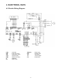
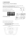
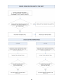
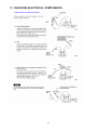
TECHNICAL DATA & SERVICE MANUAL
ULISSE 13PCLA
AUG38PCLI
Model No.
AUG38PCLI
0.8180.516.0
Product Code No.
39.7028.942
11/2006
IMPORTANT!
Please read before installation
This air conditioning system meets strict safety and operating
standards.
For the installer or service person, it is important to install or
service the system so that it operates safely and efficiently.
For safe installation and trouble-free operation, you must:
• Carefully read this instruction booklet before beginning.
• Follow each installation or repair step exactly as shown.
• Observe all local, state and national electrical codes.
• Pay close attention to all warning and caution notices given in
this manual.
•The unit must be supplied with a dedicated electrical line.
• Ground the unit following local electrical codes.
• The Yellow/Green wire cannot be used for any connection
different from the ground connection.
• Connect all wiring tightly. Loose wiring may cause overheating
at connection points and a possible fire hazard.
• Do not allow wiring to touch the refrigerant tubing, compressor,
or any moving parts of the fan.
• Do not use multi-core cable when wiring the power supply and
control lines. Use separate cables for each type of line.
When transporting
Be careful when picking up and moving the indoor and outdoor
units. Get a partner to help, and bend your knees when lifting to
reduce strain on your back. Sharp edges or thin aluminium fins on
the air conditioner can cut your fingers.
WARNING
This symbol refers to a hazard or unsafe practice which can result
in severe personal injury or death.
When installing...
… In a ceiling
Make sure the ceiling is strong enough to hold the unit-weight.
It may be necessary to build a strong wooden or metal frame to
provide added support.
… In a room
CAUTION
This symbol refers to a hazard or unsafe practice which can result
in personal injury or product or property damage.
Properly insulate any tubing run inside a room to prevent
"sweating", which can cause dripping and water damage to
walls and floors.
... In moist or uneven locations
If necessary, get help
These instructions are all you need for most installation sites and
maintenance conditions.
If you require help for a special problem, contact our sale/service
outlet or your certified dealer for additional instructions.
Use a raised concrete base to provide a solid level foundation
for the outdoor unit. This prevents damage and abnormal
vibrations.
... In area with strong winds
Securely anchor the outdoor unit down with bolts and a metal
frame. Provide a suitable air baffle.
In case of improper installation
The manufacturer shall in no way be responsible for improper
installation or maintenance service, including failure to follow the
instructions in this document.
... In a snowy area (for heat pump-type systems)
SPECIAL PRECAUTIONS
When connecting refrigerant tubing
• During installation, connect before the refrigerant system and
then the wiring one; proceed in the reverse orden when removing
the units.
• Keep all tubing runs as short as possible.
• Use the flare method for connecting tubing.
• Apply refrigerant lubricant to the matching surfaces of the flare
and union tubes before connecting them; screw by hand and
then tighten the nut with a torque wrench for a leak-free
connection.
• Check carefully for leaks before starting the test run.
WARNING
When wiring
ELECTRICAL SHOCK CAN CAUSE SEVERE
PERSONAL INJURY OR DEATH. ONLY QUALIFIED,
EXPERIENCED ELECTRICIANS SHOULD ATTEMPT
TO WIRE THIS SYSTEM.
• Do not supply power to the unit until all wiring and tubing are
completed or reconnected and checked, to ensure the grounding.
• Highly dangerous electrical voltages are used in this system.
Carefully refer to the wiring diagram and these instructions when
wiring.
Improper connections and inadequate grounding can cause
accidental injury and death.
2
Install the outdoor unit on a raised platform that is higher then
drifting snow. Provide snow vents.
NOTE:
Depending on the system type, liquid and gas lines may be either
narrow or wide. Therefore, to avoid confusion, the refrigerant
tubing for your particular model is specified as narrow tube for
liquid, wide tube for gas.
When servicing
• Turn the power OFF at the main power board before opening
the unit to check or repair electrical parts and wiring.
• Keep your fingers and clothing away from any moving parts.
• Clean up the site after the work, remembering to check that no
metal scraps or bits of wiring have been left inside the unit being
serviced.
• Ventilate the room during the installation or testing the refrigeration
system; make sure that, after the installation, no gas leaks are
present, because this could produce toxic gas and dangerous
if in contact with flames or heat-sources.
Table of Contents
Page
1. SPECIFICATIONS
1-1 Unit specifications
1-2 Major Component specifications
1-3 Other Component specifications
4
4
5-6
6
2. DIMENSIONAL DATA
2-1 Unit Dimensions
7
7
3. REFRIGERANT FLOW DATA
3-1 Refrigerant Flow Diagram
8
8
4. ELECTRICAL DATA
4-1 Electric Wiring Diagram
9
9
5. PERFORMANCE DATA
5-1 Performance Chart
10
10
6. FUNCTIONS
6-1 Cool Mode Operation
6-2 Dry Mode Operation
6-3 Fan Mode Operation
6-4 Auto Fan Speed
6-5 Forced Mode
6-6 Protection Operation in Cool and Dry Mode
6-7 I FEEL Function
6-8 NIGHT Function
6-9 Drain Pump
11
11
12
12
12
13
13
14
14
14
7. DIAGNOSTIC
15
8. JUMPERS CONFIGURATION
16
9. MAINTENANCE
17
10. TROUBLESHOOTING
18-25
11. CHECKING ELECTRICAL COMPONENTS
26-27
3
1. SPECIFICATIONS
1-1 Unit Specifications
AUG38PCLI
230 V ~ 50 Hz
Power Source
Voltage Rating
V
230
Available Voltage Range
V
198 - 264
Running Ampere
A
5,60
W
1245
Power Input
0,96
Power Factor
Performance
Capacity
Features
Controls / Temperature Controls
Control Unit
Timer
Fan Speed Indoor / Outdoor Unit
Airflow Direction
Vertical
Orizzontal
Air Filter
Compressor
Refrigerant Gas
Refrigerant Standard Charge at Shipment
Refrigerant Control
Condensate Drain System
Net Weight
13640
4,00
400/375/335
1,90
55/54/52
62
BTU/h
kW
m³/h
l/h
dB-A
dB-A
Air Circulation
High/Med./Low
Moisture Removal
High Speed
Power Noise Level Indoor Unit (1) High/Med./Low
Power Noise Level Outdoor Unit (1)
Outdoor Unit
35
A
Compressor Locked Rotor Amperes
Dimensions & Weight
Indoor Unit
3,21
W/W
C.O.P.
g
Height
Width
Depth
Height
Width
Depth
Internal Unit
External Unit
Microprocessor / I.C. thermostat
Wireless remote control
ON/OFF 24 Hours & Daily Program
3 and Auto / 1
Manual
Manual
Washable/ Easy Access
Rotary (Hermetic)
R410A
1150
Capillary Tube
Automatic with Pump
790
mm
580
mm
245
mm
490
mm
525
mm
250
mm
44
kg
15
kg
DATA SUBJECT TO CHANGE WITHOUT NOTICE
NOTE
Rating Cooling Conditions:
- Outside Air Temperature:
- Inside Air Temperature:
35°C DB
27°C DB, 19°C WB
(1) Reference data: room size 100 m³, reverberation time 0,5 s, distance 2 m.
4
1-2 Major Component Specifications
AUG38PCLI
Controller PCB
Model
Controls
Control Circuit Fuse (F1)
Jumper Setting JP1 … JP5
SAC ON-OFF IDU
Microprocessor
250VAC - 3,15A - T
2,54mm - 5 pcs
SAC WREM
Remote Control Unit
Thermistor Coil Sensor
Resistance at 25°C
kΩ
NTC (with Brass Pipe)
10 ± 3%
Thermistor Room Sensor (TH Room)
Resistance at 25°C
kΩ
10 ± 5%
Fan Motor Indoor Unit (FMI)
Model
Number / Diameter / Length
No. Of Pole - RPM High/Med./Low (230V)
Nominal Input
Coil Resistance at 25°C
Safety Device
Setting
mm
W
Ω
Ω
Ω
Ω
Operating temp. Open
Close
Run Capacitor (C)
µF
VAC
Fan Motor Outdoor Unit (FMO)
Model
Diameter
No. Of Pole / RPM (230V)
Nominal Input
Coil Resistance at 25°C
Safety Device
Setting
W
cc
cc
Ω
Ω
µF
VAC
Rotary (Hermetic)
80235455
3680
--520
*C-R : 2402
*C-S : 3582
30
450
W
Ω
Ω
Operating temp. Open
Close
Compressor
Model
Nominal Cooling Capacity
Compressor Oil: RB68A or Freol Alpha68M
Compressor Oil: DAPHNE FV68S or equivalent
Coil Resistance
at 20°C
*at 25°C
Run Capacitor (C)
Overload Relay (OLR)
Operating Temperature
µF
VAC
K35610-MO1525
Ø 340
6 / 885
75
BLU-BRN: 230 ± 5%
BLU-BLK: 243 ± 5%
Internal Bimetallic Type
150 ± 5
Autoreset
2,5
450
mm
Run Capacitor (C)
Short Time Trip
°C
Open
Close
6-16 Sec. At 25°C
5
K35406-MO2024
Cross-Flow / Ø 100 / 410
4 - 1350/1275/1165
27
GRY-WHT: 545 ÷ 630 ± 5%
WHT-VLT: 92 ÷ 105 ± 5%
VLT-ORG: 62 ÷ 71 ± 5%
GRY-BRN: 78 ÷ 90 ± 5%
Internal Bimetallic Type
150 ± 10
Autoreset
2,00
440
°C
°C
°C
A
External
150 ± 5%
69 ± 11%
23,5
DATA SUBJECT TO CHANGE WITHOUT NOTICE
AUG38PCLI
Condensate Pump
Model
Rating
Nominal Input
Coil Resistance at 20°C
Safety Float Switch
Model
Contact Rating
Float
W
Ω
Up
Down
Heat Exchanger Coil (Evaporator)
Coil
Rows
Fin Pitch
Face Area
mm
m²
Heat Exchanger Coil (Condenser)
Coil
Rows
Fin Pitch
Face Area
PC 95643
230V - 50Hz
12 ± 10%
122 ± 10%
F83161,3
10(4)A - 250VAC
Open
Close
Alluminium Plate Fin / Copper Tube
2
1,8
0,185
Alluminium Plate Fin / Copper Tube
3
1,6
mm
0,3
m²
DATA SUBJECT TO CHANGE WITHOUT NOTICE
1-3 Other Component Specifications
OPERATING RANGE
Indoor Air Intake
Outdoor Air Intake
Temperature
Temperature
32°C DB / 23°C WB
46°C DB
19°C DB / 14°C WB
19°C DB
32°C BS / 80% R.U.
43°C DB
16°C BS / 80% R.U.
16°C DB
DATA SUBJECT TO CHANGE WITHOUT NOTICE
Temperature
Cooling
Dry
Maximun
Minimun
Maximun
Minimun
6
2. DIMENSIONAL DATA
2-1 Unit Dimensions
A
E
C
B
D
AUG38PCLI
A
B
C
D
E
F
790
580
245
525
490
250
7
F
3. REFRIGERANT FLOW DATA
3-1 Refrigerant Flow Diagram
8
4. ELECTRICAL DATA
4-1 Electric Wiring Diagram
PCB
FMI
CM
OLR
FMO
C
DP
Controller
Indoor fan motor
Compressor motor
Overload relay
Outdoor fan motor
Capacitor
Drain Pump
SWITCH
IND
TH
TP
FS
9
Switch Assy
Indicator assy
Thermistor
Terminal plate
Float switch
5. PERFORMANCE DATA
5-1 Performance Chart
Operation characteristics with relative humidity around 50%.
OPERATING CURRENT (A)
AUG38PCLI
9
8
32 °C
27 °C
21 °C
7
6
5
20
25
30
35
40
EXTERNAL TEMPERATURE (°C)
10
45
50
6. FUNCTIONS
6-1 Cool Mode Operation
In Cooling Mode, the operation of the compressor (CM), Outdoor Fan (FMO) and Indoor Fan (FMI) are
determined by the difference between the room air temperature (RAT) and the set point temperature (SPT)
as shown in the graph.
NOTES
1. In this graph, the FMI is operating with the “Auto Fan Speed” setting. If the user has selected the Low,
Medium or High fan speed, the FMI will run constantly at that speed only.
2. In addition to the temperature difference of above, the operations of the main components (CM, FMO,
FMI) is also controlled by protection delays. That is: - the minimum off time of compressor is 3 minutes. - the minimum off time of compressor is 3 minutes. - the indoor fan can change speed only after it has operated at the same speed for 30 sec if in AUTO
and 1 sec for the other settings (High, Med, Low).
11
6-2 Dry Mode Operation
Dry operation remove moisture from indoor air running, in cooling mode, at a low level without reducing the
ambient temperature. This is done cycling ON and OFF indoor and outdoor units according to below.
ROOM
TEMPERATURE
DRY LEVEL
≥ SPT+2°C
LEVEL 0
< SPT+2°C
≥ SPT-1°C
LEVEL 1
< SPT-1°C
≥ 15°C
LEVEL 2
< 15°C
DRY OFF ZONE
Operation according to COOLING mode
CM ON
FMO ON
FMI switches between L and OFF (30 seconds)
CM switches 9 minutes OFF and 3 minutes ON
FMO switches 9 minutes OFF and 3 minutes ON
FMI switches OFF and L during CM operation
CM OFF
FMO OFF
FMI OFF
SPT = Set Point Temperature
6-3 Fan Mode Operation
With this mode, the indoor fan is turned ON while CM and FMO stay OFF all the time. The user can select
between 4 speeds: HIGH, MEDIUM and LOW.
6-4 Auto Fan Speed
With this option selected, the indoor fan speed changes automatically according to the difference between
the detected air temperature (RAT sensor) and the set point (SPT):
COOLING MODE
2 ≤ (RAT – SPT):
1 ≤ (RAT – SPT) < 2:
(RAT – SPT) < 1:
HIGH speed
MEDIUM speed
LOW speed
NOTE
SPT = Set Point Temperature
12
6-5 Forced Mode
In this mode the system operates (COOLING or HEATING mode – fixed settings) or is switched off by
means of the MODE button of the indoor unit control board. The operation modes can be selected
pressing the button in a cyclic way (OFF COOL HEAT OFF…). The settings are:
COOLING mode
SET POINT temperature = 25°C
FAN SPEED = HIGH
6-6 Protection Operations in Cool and Dry Mode
Freeze-up
This protection prevents ice formation on the indoor coil heat exchanger.
The protection is activated by the indoor coil temperature (ICT sensor) and only after 6 minutes
of compressor operation.
This protection acts in 2 levels:
LEVEL 1
INDOOR FAN SPEED: ANY (as selected from remote controller)
COMPRESSOR: ON
OUTDOOR FAN: cycling (30 seconds ON B 30 seconds OFF).
DRAIN PUMP: operates according to paragraph 9.2
LEVEL 2
INDOOR FAN SPEED: ANY (as selected from remote controller)
COMPRESSOR: OFF for at least 6 minutes and until ICT ≥ 8°C
OUTDOOR FAN: OFF for at least 6 minutes and until ICT ≥ 8°C
DRAIN PUMP: always ON ( stops when exiting the protection)
The system exit this protection routine when ICT temperature rises above 8°C.
13
6-7 I FEEL Function
As standard configuration the air conditioner operates detecting the room temperature through the sensor
equipped in the wireless remote controller (icon I FEEL shown on the display). This feature provides a
personalised environment since the temperature can be detected where the remote controller is located.
It is possible to de-activate this option pressing the I FEEL button on the remote controller.
In this case the I FEEL icon is no longer displayed and room temperature is detected through the sensor
included in the indoor unit.
6-8 NIGHT Function
When this function is active, room temperature changes automatically to compensate for body temperature
variations while sleeping. After 10 hours of operation system switches automatically to OFF state.
This mode of operation is available both in COOLING and HEATING mode.
When running in this mode indoor fan is automatically switched to LOW speed.
6-9 DRAIN PUMP
Pump operates when the unit is running in COOLING and DRY modes.
The level detection is done through a float switch connected at the input FS (closed under normal condition,
and opened when water overflow). System operation is according to the following chart:
FS
Contact
30sec
20sec
30sec
20sec
14
7. DIAGNOSTIC
With this feature is possible to have a visual signal that a trouble is occurring.
This mode is always active and the signalling is made through the display board LEDS .
In case of no troubles the LEDS status follows its normal function.
NOTES
The troubles are showed according a priority list that is in case of more than one
trouble present, is always showed, at first, the one with the highest priority (1 2 3 etc).
Sensor damaged means a situation where sensor is short-circuited or opened.
In case of damaged sensors, the system (CM, FMO, FMI etc), if in OFF state, does not start.
WRONG MODE SELECTED means a situation where the operating mode chosen with remote controller
does not comply with the one allowed by jumpers settings.
Priority
1
2
3
4
5
LEDS status
TROUBLE
No parameters
RAT damaged
ICT damaged
WRONG MODE
SELECTED
Water level alarm
Effects
LD1(stby)
LD2(opr)
LD3(timer)
z
F
F
F
F
O
F
F
O
O
O
F
O
F
O
O = LED off
z = LED on
F = LED blinking
15
System does not operate
See paragraph
6-9 DRAIN PUMP
8. JUMPERS CONFIGURATION
Jumpers are located on the indoor PCB near the MODE button.
Unit is shipped with jumpers set according to the following table:
JUMPER
STATUS
JP1
open
JP2
closed
JP3
open
JP4
closed
JP5
closed
16
9. MAINTENANCE
Changing the Address of the Air Conditioner
In case of more than one air conditioner operating in the same room, it may be necessary to assign
an address to each unit in order to avoid operation conflicts.
Address is set acting on the dip-switches located on the indoor PCB and on the
remote controller. The PCB settings must match the corresponding ones on the wireless remote controller.
How to change address of the air conditioner
Dip switch is located on the indoor PCB near the buzzer.
Set the PCB to the address desidered
UNIT
ADDRESS
1
2
3
4
SETTINGS
SW1
SW2
off
off
off
on
on
off
on
on
As default switches SW1 and SW2
are in off status (PCB factory state).
How to change address on Remote Control Unit
Dip switch is located on the battery compartment.
1) Pull out the door and remove the batteries.
2) Set the switch SW1 and SW2 according to the indoor PCB settings
(do not act on SW3 and SW4)
3) Insert the batteries and pull on the door
As default switches SW1 and SW2 are in off status (remote controller factory state).
17
10. TROUBLESHOOTING
CHECK BEFORE AND AFTER «TROUBLESHOOTING»
(A) Check power supply wiring.
• Check the power supply wires are correctly connected.
(B) Check power supply.
• Check that voltage is in specified range (±10% of the rating).
• Check that power is being supplied.
• WARNING: If the following troubleshooting must be done with power supplied,
be careful not to touch any uninsulated live part that can cause ELECTRIC SHOCK.
A CIRCUIT BREAKER TRIPS OR FUSE BLOWS.
• When circuit breaker is set to ON, it trips in a few moments. Resetting is not possible.
• Measure insulation resistance. There is a possibility of ground fault.
If resistance value is 1 Mohm or less, insulation is defective.
B CIRCUIT BREAKER TRIPS IN SEVERAL MINUTES AFTER TURNING AIR CONDITIONER ON.
1 • There is the possibility of short circuit.
18
2 • The unit does not run.
C WATER LEVEL ALARM - OPERATION LAMP IS BLINKING.
Malfunctioning of the condensate drainanege system.
NOTE: In case of emergency the air conditioner can work by draining the condensate from
the little pipe into a rather short container. Extract the little pipe and remove the cap.
19
D UNIT AND COMPRESSOR DO NOT RUN.
The unit does not run when air conditioner is in the follwing conditions:
• When the room temperature is below the setting temperature.
• During the protection modes.
20
E SOME PARTS OF THE AIR CONDITIONER DO NOT OPERATE.
21
F AIR CONDITIONER OPERATES, BUT ABNORMALITIES ARE OBSERVED.
22
23
G POOR COOLING OR HEATING.
24
H EXCESSIVE COOLING OR HEATING.
I A SENSOR IS DEFECTIVE.
25
11. CHECKING ELECTRICAL COMPONENTS
26
27
Via Varese, 90 - 21013 Gallarate - VA - Italy
Tel. +39 0331 755111 - Fax +39 0331 776240
www.argoclima.com