1
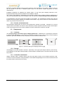
CombiSol project
Solar Combisystems Promotion and Standardisation
D6.3 : Guidelines for manufacturers and installers
Editor:
Jan Erik Nielsen (PlanEnergi)
Contributions from
Alexander Thür, Johann Breidler, Gabriele Kuhness (AEE INTEC)
Thomas Letz, Guillaume Pradier, Xavier Cholin (INES Education)
Philippe Papillon, Mickael Albaric (CEA Ines)
Chris Bales (SERC)
Barbara Mette, Jens Ullmann (ITW)
(2010)
Date
19/1/2011
Version
DRAFT
Revision
1
The sole responsibility for the content of this publication lies with the authors. It does not necessarily reflect the
opinion of the European Union. Neither the EACI nor the European Commission are responsible for any use that may
be made of the information contained therein.
CONTENTS
Figure list.......................................................................................................................... 3
Introduction ...................................................................................................................... 4
1
Guidelines for manufacturers ................................................................................... 5
1.1
General ........................................................................................................................... 5
1.2
Papers and procedures ................................................................................................. 5
1.2.1
1.2.2
1.2.3
1.2.4
1.3
Components ................................................................................................................... 7
1.3.1
1.3.2
1.3.3
1.3.4
1.3.5
1.3.6
1.3.7
1.3.8
1.3.9
2
Collector...................................................................................................................................... 7
Storage ....................................................................................................................................... 7
Controller and sensors................................................................................................................ 7
Solar loop.................................................................................................................................... 8
Expansion vessel and over temperature protection ................................................................... 8
Back-up heater ........................................................................................................................... 9
Hot water units............................................................................................................................ 9
System ...................................................................................................................................... 10
Installation................................................................................................................................. 10
Guidelines for installers .......................................................................................... 11
2.1
General ..........................................................................................................................11
2.2
Paper and procedures ..................................................................................................11
2.2.1
2.2.2
2.3
Documents for the user ............................................................................................................ 11
Service and maintenance ......................................................................................................... 11
Components ..................................................................................................................12
2.3.1
2.3.2
2.3.3
2.3.4
2.3.5
2.3.6
2.3.7
2.3.8
2.3.9
3
System specific design guidelines for the installer ..................................................................... 5
User manuals.............................................................................................................................. 6
Installer manuals......................................................................................................................... 6
Service and maintenance ........................................................................................................... 7
Collector.................................................................................................................................... 12
Storage ..................................................................................................................................... 12
Controller and sensors.............................................................................................................. 12
Solar loop.................................................................................................................................. 12
Expansion vessel and over temperature protection ................................................................. 13
Back-up heater ......................................................................................................................... 14
Hot water units.......................................................................................................................... 14
System ...................................................................................................................................... 14
Installation................................................................................................................................. 15
Bibliography ............................................................................................................. 16
D6.3: Guidelines for manufacturers and installers
page 2
Figure list
Figure 1: System layout (good example) [[3]] .................................................................................................. 5
Figure 2: Pipe connection with thermo-siphon heat trap [[3]]........................................................................... 6
Figure 3: Collectors with good emptying behaviour [[2]] ................................................................................. 7
Figure 4: Temperature sensors fixed correctly [[3]].......................................................................................... 8
Figure 5: External pipe insulation good quality of insulation and protection .................................................... 8
Figure 6: Connecting the expansion vessel [[2]] ............................................................................................. 9
Figure 7: Stagnation cooler - example [[2]] ..................................................................................................... 9
Figure 8: Domestic hot water unit - example, placed directly to the unit [[2]] ............................................... 10
Figure 9: Ökofen unit with all-in-one - example, placed directly to the unit [[2]] ........................................... 10
Figure 10: System layout (good example) [[3]] ............................................................................................. 11
Figure 11: Collectos with good emptying behaviour [[2]] .............................................................................. 12
Figure 12: Temperature sensors fixed correctly [[3]]...................................................................................... 12
Figure 13: External pipe insulation good quality of insulation and protection ............................................... 13
Figure 14: Connecting the expansion vessel [[2]] ......................................................................................... 13
Figure 15: Stagnation cooler - example [[2]] ................................................................................................. 13
Figure 16: Temperature resistant collection tank made of metal (left) but not temperature resistant collection
tank made of plastics (right) [3] ............................................................................................................... 14
Figure 17: Good example of insulated pipe connections and combination of thermo-siphon heat traps and
insulation of pipes and all other cold bridges like air vent and thermometer. Could however be better if
already from the manufacturer these heat traps were integrated/pre-assembled in the store unit. [[3]] 15
Figure 18: Switch controlled circulation pump - connected to switches in kitchen and bath room [[3]] ......... 15
D6.3: Guidelines for manufacturers and installers
page 3
Introduction
The guidelines given here are based on lessons learned in the CombiSol Project:
• Guidelines for best practise [D2.1]
• Guidelines for design and dimensioning [[1]]
• Trend analysis for “standardised systems”: Where is the market going [[2]]
• 70 installed systems have been evaluated and analysed: Where are the weak points; where to take
special care [[3]]
• 40 solar combisystems were monitored and analyzed by energy balances on a monthly basis [[4]]
The results from the systems evaluated and conclusions from the analysis done show that there are “room
for improvements”, both at product and installation level - so the guidelines here are indeed relevant.
The trend analysis shows that standardised integrated system units are now showing up in the market - it is
expected that this trend in general will lead to improved system performance.
D6.3: Guidelines for manufacturers and installers
page 4
1 Guidelines for manufacturers
1.1
General
The main focus for product and system improvements should not be on increasing the solar gains but much
more on reducing heat losses in solar combisystems.
Integrated / standardised systems/units with pre-installed closely connected components and one common
controller are recommended.
1.2
1.2.1
Papers and procedures
System specific design guidelines for the installer
Manufacturer should provide detailed and understandable guidelines for - and examples of - system layout.
Drawings of example system layouts should be given for at least:
• Installation in connection with fast reacting oil or gas back-up
• Installation in connection with slower reacting biomass back-up
Figure 1: System layout (good example) [[3]]
Manufacturer should provide rules for sizing the system and its components depending on the space
heating and hot water load (estimated annual energy consumption of the house):
• Specification of collector and storage size depending on the energy consumption of the house
• Specification of pump, piping and heat exchangers depending on collector and storage size
• Specification of size of expansion vessel and pressure setting depending on collector size (and type),
piping and height difference between collectors and expansion vessel
D6.3: Guidelines for manufacturers and installers
page 5
Double tank solution should normally be avoided - as it typically increases the system losses more
than the system gain.
As much system integration as possible is recommended:
• pre-assembled components
• integrated back-up
• one integrated controller for both solar and back-up system.
1.2.2
User manuals
Manufacturer should provide a complete, but simple and understandable user manual describing:
• the functioning of the system
• user control possibilities with recommendations for settings
• how the user detect if the system is not operating properly
The user manual should also include:
• recommendation to make a service contract with installer
• notice that the installer should fill out a commissioning check and supply the user and the
manufacturer with copies
1.2.3
Installer manuals
Besides the system specific design guidelines, a detailed installation manual should be available. Included
here should be specifications how to avoid cold bridges and instructions on how to make the necessary
heat traps.
Source: Ines Education / France
Figure 2: Pipe connection with thermo-siphon heat trap [[3]]
It is recommended that the heat traps are pre-installed to the tank.
D6.3: Guidelines for manufacturers and installers
page 6
Examples of editable detailed system layouts should be made available for the installer, making it easy for
him to provide to the user a detailed system layout of the specific system (important for future
maintenance).
Installation guidelines for installing the collector field in a way with good emptying behaviour (overtemperature protection) shall be included in the installation manual.
The control of (the different configurations and operating modes of) the system should be explained in a
clear and understandable way in the installation and user manuals. Control settings should be specified.
A commissioning check list should be provided to the installer. The manufacturer should agree with the
installer that for all system installed, the installer should send a copy of this check list to the manufacturer
and a copy should remain at the user.
1.2.4
Service and maintenance
Recommended requirements for service and maintenance should be provided - template for a service
contract which the installer can offer the user should be provided. Special reminder to keep the description
of the actual system layout and control available for future maintenance should be included.
1.3
1.3.1
Components
Collector
The collector design should have good “emptying behaviour”. Guidelines for connecting the collectors
in series/parallel depending on the number of collectors should be given order to keep a good emptying
behaviour, good flow distribution and low pressure loss for the whole collector field.
Figure 3: Collectors with good emptying behaviour [[2]]
1.3.2
Storage
Cold bridges to the tank should be avoided - especially in the upper part always heated by the back-up.
Pre-installation of heat traps where possible is recommended. Insulated caps for unused connection should
be provided.
1.3.3
Controller and sensors
Simple controller and/or controller leaving only few and logical choices to the installer should be used.
Location of sensor should be clearly described - and suitable fixings/fittings for the sensors should be used
for good thermal contact and secure fixing.
D6.3: Guidelines for manufacturers and installers
page 7
Source : AEE INTEC / Austria
Figure 4: Temperature sensors fixed correctly [[3]]
1.3.4
Solar loop
Manufacturer should deliver and/or give specifications for the piping including insulation - pre-insulated
pipes are recommended. Materials used shall fit the max. temperatures - and for the part placed outdoor fit the outdoor environment (solar radiation, rain, birds, insects, …).
Manufacturer should deliver and/or give specifications for the pumps - use of high efficiency pumps is
recommended.
Figure 5: External pipe insulation good quality of insulation and protection
1.3.5
Expansion vessel and over temperature protection
Manufacturer should deliver and/or give specifications for the expansion vessel. Rules for pressure setting
depending on collector size (and type), piping and height difference between collectors and expansion
vessel should be clear to the installer.
Specification how to install expansion vessel to avoid unnecessary heat loss should be given.
D6.3: Guidelines for manufacturers and installers
page 8
Figure 6: Connecting the expansion vessel [[2]]
Cases where “stagnation cooler” is needed should be specified - and manufacturer should deliver and/or
give specifications for such cooler.
Figure 7: Stagnation cooler - example [[2]]
Specification for safety line from safety valve shall be given:
• Temperature resistant piping with right dimensions leading to temperature resistant container
(preferably showing/indicating the fluid content).
1.3.6
Back-up heater
Units including solar and back-up systems are recommended - and this is the trend seen.
If manufacturer delivers only the solar part, recommendations and examples should be given how to
connect to the different possible back-up systems. Interaction of solar and back-up controllers should be
described. If certain back-up system types are not feasible with the solar system - this should be stated.
1.3.7
Hot water units
Separate hot water heat exchangers should be part of / close to the storage to avoid heat loss.
D6.3: Guidelines for manufacturers and installers
page 9
Figure 8: Domestic hot water unit - example, placed directly to the unit [[2]]
1.3.8
System
Manufacturer should aim at system integration and pre-assembling. This gives easier/cheaper installation
and less risk of errors.
Figure 9: Ökofen unit with all-in-one - example, placed directly to the unit [[2]]
In general there should be focus on system heat losses (including especially cold bridges). Pre-installation
of heat traps where possible is recommended. Insulated caps for fittings and unused connection should be
provided.
1.3.9
Installation
It should be noted in the installer manual that it is very important that the solar system operates on as low
temperatures as possible, hence the return temperature from the heat distribution system should be as low
as possible. In the manual hints - or references to hints - should be given: How to check if the return
temperature is higher than necessary - and how to lower it (with examples).
“On demand” hot water circulation system should be recommended.
D6.3: Guidelines for manufacturers and installers
page 10
2 Guidelines for installers
2.1
General
The main focus for product and system improvements should not be on increasing the solar gains but much
more on reducing heat losses in solar combisystems,
Integrated / standardised systems/units with pre-installed closely connected components and one common
controller are recommended.
2.2
2.2.1
Paper and procedures
Documents for the user
Installer should provide for the user
• System layout (principle diagram) - installer should recommend the user to put it a visible place
(see e.g. figure below)
• Description of the control of the system including which settings can be adjusted by the user
• Commissioning report - including check list for insulation and heat traps
• Service manual, describing service intervals and service points - the installers should offer the user
a service contract
• Service contract
Figure 10: System layout (good example) [[3]]
2.2.2
Service and maintenance
Recommended requirements for service and maintenance should be provided to the user. Special reminder
to keep the description of the actual system layout and control available for future maintenance should be
included. Template for service contract should be provided for the installer.
D6.3: Guidelines for manufacturers and installers
page 11
2.3
2.3.1
Components
Collector
The collector design should have good “emptying behaviour”. Guidelines for connecting the collectors
in series/parallel depending on the number of collectors should be given order to keep a good emptying
behaviour, good flow distribution and low pressure loss for the whole collector field.
Figure 11: Collectos with good emptying behaviour [[2]]
2.3.2
Storage
Cold bridges should be avoided. Pre-installation of heat traps where possible is recommended. Insulated
caps for unused connection should be provided.
2.3.3
Controller and sensors
Sensor location is critical - and immersion sleeves should fit the sensor diameter for good thermal contact.
Sensors should be secured/fixed in the location.
Source : AEE INTEC / Austria
Figure 12: Temperature sensors fixed correctly [[3]]
2.3.4
Solar loop
Manufacturer should deliver and/or give specifications for the piping including insulation. Materials used
shall fit the max. temperatures and for the part placed outdoor - fit the outdoor environment (solar radiation,
rain, birds, insects, …)
D6.3: Guidelines for manufacturers and installers
page 12
Figure 13: External pipe insulation good quality of insulation and protection
2.3.5
Expansion vessel and over temperature protection
Expansion vessel is to be put on the “cold side” and connected in the top (see figure) - or via heat trap.
Pressure setting and dimensioning should be done according to manufacturer’s instructions for the specific
type and size of installation.
Figure 14: Connecting the expansion vessel [[2]]
Check if stagnation cooler is necessary - to be checked with manufacturer recommendations.
Figure 15: Stagnation cooler - example [[2]]
Safety line from safety valve shall be temeperature resistant and lead to temperature resistant container.
D6.3: Guidelines for manufacturers and installers
page 13
Source: AEE INTEC / Austria - OK
Source: ITW / Germany - NOT OK
Figure 16: Temperature resistant collection tank made of metal (left) but not temperature resistant collection
tank made of plastics (right) [3]
2.3.6
Back-up heater
Before installing the solar system in connection with an existing back-up boiler/unit it is recommended to
investigate possibilities /relevance for exchanging this boiler / unit at the same time.
If existing boiler / unit is not exchanged - it should be assured that the control of the solar part of the system
and the back-up system works without conflicts.
Units including solar and back-up systems are recommended.
2.3.7
Hot water units
Separate hot water heat exchangers should be part of / close to the storage to avoid heat loss.
2.3.8
System
Manufacturer should aim at system integration and pre-assembling. This gives easier/cheaper installation
and less little risk of errors.
In general there should be focus on system heat losses (including especially cold bridges). Pre-installation
of heat traps where possible is recommended. Insulated caps for fittings and unused connection should be
provided.
D6.3: Guidelines for manufacturers and installers
page 14
Source : AEE INTEC
Figure 17: Good example of insulated pipe connections and combination of thermo-siphon heat traps and
insulation of pipes and all other cold bridges like air vent and thermometer. Could however be better if
already from the manufacturer these heat traps were integrated/pre-assembled in the store unit. [[3]]
2.3.9
Installation
The installer should check if the return temperature is higher than necessary - and take measures to lower it
- guidelines from manufacturer should be followed.
“On demand” hot water circulation system should be recommended.
Source : AEE INTEC
Figure 18: Switch controlled circulation pump - connected to switches in kitchen and bath room [[3]]
The installer should check if e.g. the storage is fully insulated from the manufacturer - if not, the installer
should finish the insulation. Especially insulation of the top part of the tank is VERY IMPORTANT.
D6.3: Guidelines for manufacturers and installers
page 15
3 Bibliography
[1]
[2]
[3]
[4]
Thür A. et al,
Thür A. et al,
CombiSol“
Thür A. et al,
Letz T. et.al,
2010, D2.3 „Guidelines for Design and Dimensioning"
2010, D2.4 „Updated State of the Art Report Of Solar Combisystems Analysed within
2010, D5.4 „Summary of the Qualitative Evaluation of Solar Combisystems“
2010, D4.4 “ Comparison of results of all monitored plants”
D6.3: Guidelines for manufacturers and installers
page 16