1
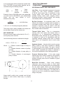
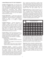
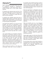
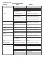
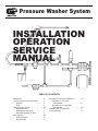
Pressure Washer System
INSTALLATION
OPERATION
SERVICE
MANUAL
TABLE OF CONTENTS
Introduction . . . . . . . . . . . . . . . . . . . . . . . .2
Typical Operation & Requirements . . . . . .2
Pressure . . . . . . . . . . . . . . . . . . . . . . .2
Flow . . . . . . . . . . . . . . . . . . . . . . . . . .2
Designing Your System . . . . . . . . . . . . . . .3-5
Pump Selection . . . . . . . . . . . . . . . . . .3
Motor/Engine Selection . . . . . . . . . . . .3
Determining Spray Tip Size . . . . . . . .5
Drive System . . . . . . . . . . . . . . . . . . . . . . .5-6
Pulley Selection . . . . . . . . . . . . . . . . .5
Belt Selection . . . . . . . . . . . . . . . . . . .6
Selecting Remaining Components . . . . . . . .6-7
Upstream or Inlet Side
Components . . . . . . . . . . . . . . . . . . . . .6
Downstream or Outlet Side
Components . . . . . . . . . . . . . . . . . . . . .6-7
Installing Your Components . . . . . . . . . . . . .8
Troubleshooting . . . . . . . . . . . . . . . . . . . . . .9
spray gun is open or closed, therefore a device is
needed to control the direction of flow, either allowing
the flow to go through the open spray gun, or
redirecting (by-passing) the flow back to the inbound
side of the pump when the spray gun is closed.
Without an unloading or regulating valve, dangerously
high pressures will be produced when the spray gun is
closed because the water being forced out of the pump
has no place to go. Serious bodily injury or
property damage could be caused by failure to
properly utilize an appropriate unloader or regulator
valve in your pressure washer system. As a safety
device, at least one pressure relief valve should be
installed in the outbound side of the pump to guard
against failure of component parts, and the
development of dangerously high pressure.
INTRODUCTION
Thank you for purchasing a GENERAL PUMP
pressure washer pump. With proper installation and
maintenance it will provide you with many years of
dependable, trouble-free service.
This manual was developed as a basic guide to
understanding the operation and requirements,
installation, and servicing of GENERAL PUMP
positive displacement pumps.
Pressure cleaning equipment is potentially
hazardous and could cause personal injury or
property damage if installed, repaired or operated
in an unsafe manner, or in a manner which is not
consistent with the manufacturer’s recommendations
or requirements.
Cleaning chemicals or detergents may be introduced
into the flow of water either inbound or outbound of
the pump. An inbound or upstream type of chemical
injector simply uses the pumps ability to draw or suck
fluid in to introduce a chemical into the stream of water.
Care must be taken to avoid introducing any
chemicals which are not compatible with the materials
in the pump and downstream components. An
upstream injector does allow chemicals to be applied
to the work surface at the normal high working
pressure of the system. An outbound or downstream
type of chemical injector uses a venturi (very similar
to that used in an automobile carburetor) to draw a
chemical into the water stream. A downstream injector
requires low pressure to activate chemical flow.
Low pressure is achieved by changing to a large sized
spray tip, or opening up a large orifice at the
outlet end of the spray gun using an adjustable
nozzle or a double lance. There are several
advantages to using a downstream injector over using
an upstream type.
There are many manufacturers of pressure washer
pumps and complementary components. Be sure that
the required components that you choose to use
are consistent with the high quality standards of
GENERAL PUMP. GENERAL PUMP does not
assume liability or responsibility for the design or
operation of a customer’s high pressure system.
TYPICAL OPERATION AND
REQUIREMENTS
PRESSURE
The pressure produced in a pressure washer
system is the result of forcing a known volume
(or flow) of water through a known size orifice
(spray tip). Pressure is measured in pounds per
square inch (PSI).
FLOW
The flow or volume produced in a pressure
washer system is determined by the speed that
the pump shaft is rotated (RPM). The faster the
shaft is rotated, the higher the output volume.
The flow or volume is measured in gallons per
minute (GPM).
1. Fewer component parts are exposed to the
cleaning chemicals, extending system life.
2. The operator can control the flow of chemical
(on and off) by changing the system pressure at
the nozzle.
3. Applying chemical at low pressure is more
economical because less chemical bounces off
the work surface.
The pump, which is driven by an electric motor or a
gas engine, draws or accepts filtered water in through
a series of inlet check valves as the plungers move
back. As the plungers move forward, the inlet valves
close,
forcing
the
water
to
travel
through a series of outlet check valves, and to the
outbound side of the pump.
Heated pressure washers and steam cleaners
increase the ability of a high pressure flow of water to
break down dirt and grease. They also increase the
action of most cleaning chemicals. These systems are
very complex, and add more potential for
personal injury and property damage hazards. Design
of these systems requires many more additional
components as well as experienced design personnel
with knowledge of fuels, heat transfers, electronics,
etc.
After the water exits the pump, its flow direction
must be controlled with an unloading or regulating
valve. A positive displacement pump is always
delivering a certain volume of water whether the
2
TYPICAL PRESSURE WASHER SYSTEM
SPRAY GUN
HIGH
PRESSURE
HOSE
SPRAY TIP
WAND
UNLOADER OR
REGULATOR VALVE
PRESSURE
RELIEF VALVE
PULSATION
DAMPENER
PRESSURE
GAUGE
PUMP
CHEMICAL
INJECTOR
THERMAL
RELIEF
VALVE
FLUID
BY-PASS
HOSE
POWER SOURCE
(MOTOR/ENGINE)
INLET FILTER
DRIVE
SYSTEM
DESIGNING YOUR SYSTEM
PUMP SELECTION
The heart of any pressure washer system is the high
pressure pump. Size the pump according to your
cleaning needs. Higher than required pressure and
volume will cause needless wear of all components
in the system, and could actually damage your work
surface instead of cleaning it. Never exceed the
maximum pressures of rotation speed as is stated on
the Technical Data Sheet supplied with each pump.
MOTOR/ENGINE SELECTION
The size of the electric motor or gas engine required
to drive your pump is determined by the pump GPM
and PSI output desired. Refer to the Technical Data
Sheet supplied with each pump, or the following
chart. Both charts are based on electric horsepower
requirements; for gas engines multiply by 1.8. Gas
engine output horsepower varies with running RPM.
Be sure to run a gas engine fast enough to supply
required horsepower, but do not exceed
manufacturer’s specifications.
Refer to the Technical Data Sheet to determine what
pump RPM is needed to deliver your required GPM
output.
3
ELECTRIC MOTOR HORSEPOWER REQUIRED TO DRIVE A PUMP
GPM
100 PSI
200 PSI
250 PSI
300 PSI
400 PSI
500 PSI
700 PSI
.5
.04
.07
.09
.11
.14
.18
.26
1000 PSI 1250 PSI 1500 PSI 2000 PSI 2500 PSI 3000 PSI 4000 PSI
.35
.44
.53
.70
.88
1.10
1.40
1.0
.07
.14
.18
.21
.28
.35
.52
.70
.88
1.05
1.40
7.76
1.92
2.80
1.5
.10
.21
.26
.31
.41
.52
.77
1.03
1.29
1.55
2.06
2.58
3.09
4.12
2.0
.14
.28
.35
.42
.56
.70
1.04
1.40
1.76
2.10
2.80
3.53
4.20
5.60
2.5
.17
.34
.43
.51
.69
.86
1.29
1.72
2.15
2.58
3.44
4.30
5.14
6.88
3.0
.21
.42
.53
.63
.84
1.05
1.56
2.10
2.64
3.15
4.20
5.28
6.30
8.40
3.5
.24
.48
.60
.72
.96
1.20
1.80
2.40
3.00
3.60
4.80
6.00
7.20
9.60
4.0
.28
.56
.70
.84
1.12
1.40
2.08
2.80
3.52
4.20
5.60
7.04
8.40
11.20
5.0
.35
.70
.88
1.05
1.40
1.75
2.60
3.50
4.40
5.25
7.00
8.80
10.50
14.00
6.0
.42
.84
1.05
1.26
1.68
2.10
3.12
4.20
5.28
6.30
8.40
10.56
12.60
16.50
7.0
.49
.98
1.23
1.47
1.96
2.45
3.64
4.90
6.16
7.35
9.80
12.32
14.70
19.60
8.0
.56
1.12
1.40
1.68
2.24
2.80
4.16
5.60
7.04
8.40
11.20
14.08
16.80
22.40
9.0
.62
1.24
1.55
1.86
2.48
3.10
4.65
6.18
7.73
9.28
12.40
15.56
18.58
24.80
10.0
.70
1.40
1.75
2.10
2.80
3.50
5.20
7.00
8.80
10.50
14.00
17.60
21.00
28.00
NOTES:
1.
2.
A gasoline engine should be sized 1.8 times the electric horsepower requirement.
Always select a motor/engine with a horsepower rating above the minimum requirements shown above.
Example: 5.0 GPM - 1250 PSI is 4.40 minimum electric horsepower requirement, use a 5
horsepower electric motor.
If you wish to direct drive your pump from an electric motor, you may want to use a “C” face motor.
Check with your motor supplier for technical information.
SPRAY TIP SELECTION CHART
OUTPUT VOLUME (GPM) AT VARIOUS PRESSURES (PSI)
*TIP
SIZE
ORIFICE
DIA. (“)
40 PSI
100 PSI
250 PSI
500 PSI
600 PSI
700 PSI
800 PSI
1000 PSI
1200 PSI
1500 PSI
2000 PSI
2500 PSI
3000 PSI
3500 PSI
4000 PSI
2
.034
.20
.32
.50
.71
.77
.80
.89
1.0
1.1
1.2
1.4
1.6
1.7
1.9
2.0
4
.052
.40
.63
1.00
1.40
1.60
1.70
1.80
2.0
2.2
2.5
2.8
3.1
3.5
3.8
4.0
4.5
.055
.45
.71
1.10
1.50
1.70
1.90
2.00
2.2
2.4
2.8
3.0
3.6
3.9
4.3
4.5
5
.057
.50
.79
1.30
1.80
1.90
2.10
2.20
2.5
2.8
3.1
3.6
4.0
4.4
4.7
5.0
5.5
.060
.55
.87
1.40
1.90
2.10
2.30
2.50
2.8
3.0
3.4
3.8
4.4
4.8
5.2
5.5
6
.062
.60
.95
1.50
2.10
2.30
2.50
2.70
3.0
3.2
3.7
4.2
4.8
5.2
5.6
6.0
6.5
.064
.65
1.00
1.70
2.30
2.50
2.70
2.90
3.3
3.6
4.0
4.6
5.2
5.7
6.0
6.5
7
.067
.70
1.10
1.80
2.50
2.70
2.90
3.10
3.5
3.8
4.3
5.0
5.6
6.1
6.6
7.0
7.5
.070
.75
1.20
1.90
2.70
2.90
3.20
3.40
3.8
4.1
4.6
5.3
6.0
6.5
7.0
7.5
8
.072
.80
1.30
2.00
2.80
3.10
3.40
3.60
4.0
4.4
5.0
5.6
6.2
7.0
7.5
8.0
8.5
.074
.85
1.30
2.20
3.00
3.30
3.60
3.80
4.3
4.6
5.3
6.0
6.7
7.4
8.0
8.5
9
.076
.90
1.40
2.30
3.20
3.50
3.80
4.00
4.5
5.0
5.5
5.4
7.1
7.8
8.5
9.0
9.5
.078
.95
1.50
2.40
3.40
3.70
4.00
4.30
4.8
5.2
5.8
6.8
7.6
8.3
9.0
9.5
10
.080
1.00
1.60
2.50
3.50
3.90
4.20
4.50
5.0
5.4
6.1
7.0
8.0
8.7
9.4
10.0
12
.087
1.20
1.90
3.00
4.20
4.60
5.00
5.40
6.0
6.4
7.3
8.4
9.5
10.4
11.2
12.0
15
.094
1.50
2.40
3.80
5.30
5.80
6.40
6.80
7.5
8.2
9.2
10.6
12.0
12.9
14.0
15.0
20
.109
2.00
3.20
5.00
7.10
7.80
8.40
9.00
10.0
10.8
12.2
14.2
16.0
17.4
18.8
20.0
30
.141
3.00
4.70
7.50
10.60
11.60
12.80
13.60
15.00
16.40
18.40
21.2
24.0
26.0
28.0
30.0
40
.156
4.00
6.30
10.00
14.20
15.60
16.80
18.00
20.00
21.60
24.40
28.4
32.0
34.8
37.6
40.0
*
A commonly used standard for tip size is the “nozzle number” which is equivalent to the nozzle
capacity in GPM at 4000 PSI. Spray angle does not affect nozzle volume.
4
PULLEY SELECTION
There are many typed of belts and pulleys available,
the following is a basic guide. Manufacturer’s
representatives should be consulted concerning your
specific requirements.
DETERMINING SPRAY TIP SIZE
As stated earlier in this manual, the output pressure
is determined by forcing the output volume of water
through a certain size orifice or spray tip. Stray tip
size is a very important factor of proper pressure
washer performance, using a tip that is sized too
small will allow overpressurization of the pump and
components. You must know your output GPM and
your output PSI to properly select a spray tip size.
To use the chart on Page 4, find the desired PSI,
read down the column until you find the output GPM
closest to your pump application. Read to the far
left to find the spray tip number and orifice diameter.
Example: 1000 PSI at 4.0 GPM needs a number 8
spray tip.
From the MOTOR Pulley Guide (below), determine the
pulley size (A, B or C section), and number and
size (A, B or C section) of belt required. The larger in
size and/or number of belts used will increase the
life of belts. Be sure to consider space limitations of
your finished assembly.
MOTOR PULLEY GUIDE
“A” Section Belt
Spray tips are available in various spray angles. It is
advisable to have different spray angle tips in the
same size for different cleaning applications. Some
spray tips or nozzles are available with an adjustable
spray angle.
“C” Section Belt
To Transmit:
HORSEPOWER
1 Belt
Single
Groove
Pulley
2 Belts
Double
Groove
Pulley
1 Belt
Single
Groove
Pulley
2 Belts
Double
Groove
Pulley
1 Belt
Single
Groove
Pulley
DRIVE SYSTEM
There are three common methods of driving or
connecting the pump and motor/engine. Direct drive
and gear reduction drive require special components
that are matched to the pump and to the motor/
engine, as well as other technical considerations. A
belt and pulley system is the recommended method
of driving the pump because it allows easy reduction
of the motor/engine RPM to your required pump
RPM, as well as absorbing shocks produced by
both the engine and the pump.
“B” Section Belt
1
2-1/2 Dia.
-
-
-
-
1-1/2
3
-
-
-
-
2
3-1/4
-
-
-
-
3
3-3/4
3 Dia,
4 Dia.
3-1/2 Dia.
-
5
5-1/4
3-1/2
5
5
-
7-1/2
-
4-1/2
6
5
-
10
-
5-1/4
8
5
8 Dia.
15
-
7
10
6
9
20
-
9
-
7
10
To determine pump pulley size (based on a 1725
RPM motor), find the motor pulley size on the chart
below, follow the column down untif you find your
required pump RPM to meet your requirements, or
the next higher RPM. Follow the column to the left
to find pump pulley diameter.
PUMP PULLEY
OUTSIDE DIAMETER
(INCHES)
2-1/2
2-1/2
1725
2-1/4
1574
1725
3
1431
1590
1725
3-1/4
1310
1460
1604
1725
3-1/2
1210
1346
1480
1615
1725
3-3/4
1125
1250
1375
1500
1625
1725
4
1050
1168
1283
1400
1518
1634
1725
4-1/4
985
1094
1201
1311
1420
1530
1640
1725
4-1/2
926
1030
1131
1235
1339
1440
1543
1650
1725
4-3/4
876
947
1070
1168
1265
1362
1460
1558
1652
1725
5
830
922
1013
1105
1198
1290
1382
1473
1568
1660
1725
5-1/4
788
975
963
1050
1137
1225
1312
1400
1487
1575
1662
1725
5-1/2
750
934
917
1000
1082
1167
1250
1333
1417
1500
1581
1646
1725
5-3/4
715
795
875
955
1032
1113
1192
1272
1350
1430
1510
1575
1650
1725
6
685
760
937
913
990
1065
1140
1217
1290
1370
1450
1509
1581
1653
1725
6-1/2
630
700
771
840
910
980
1050
1120
1190
1260
1330
1393
1460
1526
1292
1725
7
584
648
713
778
843
907
973
1039
1102
1168
1231
1294
1355
1417
1500
1602
1725
8
507
564
620
676
734
789
845
902
959
1016
1072
1132
1186
1240
1312
1421
1509
1725
9
450
500
550
600
650
700
750
800
850
900
950
1066
1054
1102
1166
1263
1342
1533
1725
10
405
450
495
540
585
630
675
720
765
810
855
906
949
992
1050
1137
1208
1380
1553
1725
11
366
407
448
488
530
570
610
652
692
733
774
823
836
902
954
1034
1098
1255
1411
1568
1725
12
336
373
410
446
485
522
560
596
634
671
708
755
791
827
875
947
1006
1150
1294
1438
1591
1725
13
309
343
378
412
447
480
515
549
584
618
652
697
730
763
807
875
929
1062
1194
1327
1460
1592
1725
14
286
318
650
382
414
445
477
509
540
573
605
647
678
708
750
813
863
986
1109
1232
1355
1479
1602
1725
15
267
297
326
358
386
415
445
475
505
534
564
604
633
661
700
758
805
920
1035
1150
1265
1380
1495
1610
16
250
278
306
333
361
389
416
445
473
500
528
566
293
620
656
711
755
863
970
1078
1186
1294
1402
1509
MOTOR PULLEY OUTSIDE DIAMETER (INCHES)
2-3/4
3
3-1/4
3-1/2
3-3/4
4
4-1/4
4-1/2
4--3/4
5
5
5-1/4
5-1/2
5-3/4
6
6-1/2
7
8
9
10
11
12
13
14
SELECTING REMAINING
COMPONENTS
If your motor/engine will be operated at a speed other
than 1725 RPM, the pump pulley diameter can be
calculated using the following formula.
RPM
Ratio
X
Motor
Pulley
Diameter
X
UPSTREAM OR INLET SIDE COMPONENTS
Pump
Pulley
Diameter
Inlet Filter - A very important component to increase
system life and avoid operating problems.
A 60-120 mesh screen filter is necessary to stop
foreign matter from entering the system and
possibly holding valves open, clogging orifices,
scratching plungers, tearing packing, and causing
unnecessary wear on all components.
Example: Using a 1200 RPM motor, and a pump that
you want to turn at 850 RPM for your desired GPM
output, and you have chosen a 4-1/2”
diameter motor pulley:
1200
850
=
By-Pass Provision - As mentioned earlier in this
manual, the unloader or regulator valve by-passes or
recirculates pumped water when the gun trigger is
released. A provision must be made in the inlet
plumbing (or inlet water holding tank) to accept this
flow of water without restrictions.
1.412 RPM Ratio
1.412 x 4.5 = 6.39 actual pump pulley diameter
There may not be a pulley available in the exact size
as calculated. Simply use the closest one.
Thermal Relief Valve - This is a temperature
sensing valve that opens and dumps water to
atmosphere at a predetermined temperature.
Recirculating water (through the by-pass loop) has
a tendency to heat up to temperatures that can
eventually damage internal pump parts. A thermal
relief valve is an inexpensive way to avoid colstly
repairs.
BELT SELECTION
Be sure to use the same section belts (A, B, or C)
as the pulleys were sized for.
Use the following formula to calculate belt length:
L=2(C) + 1.57 (D + d)
Where:
+
(D - d)2
4C
Upstream Injector - A device which uses the pumps
ability to draw or suck fluid to introduce a cleaning
chemical into the water stream. This type of injector
is recommended for very mild chemicals only as the
entire system (especially the pump) is exposed to
the corrosive tendencies of the cleaning chemicals.
L = Effective outside length of belt(s) in
inches.
C = Distance between centers of pulleys
in inches.
D = Outside diameter of pump pulley in
inches.
d = Outside diameter of motor/engine
pulley in inches.
Pressure Reducing Valve - If the water supply
entering the pump is above maximum inlet pressure
rating called out on the Pump Data Sheet. A
pressure reducing valve must be installed for proper
pumpoperation.
Back-Flow Preventer - When using cleaning
chemicals, care must be taken to avoid these
chemicals from being back-flushed and contaminating
the city water supply. Check your local plumbing
codes. An alternative option to a “back-flow preventer”
is the use of a water holding tank. If a holding tank is
used, be sure not to exceed the negative pressure
rating of the pump.
Always install a safety cover or guard over belt and
pulleys to avoid serious bodily injury or property
damage.
6
DOWNSTREAM OR OUTLET SIDE COMPONENTS
PSI, to activate the chemical flow. A double nozzle
holder, rollover nozzle, and a double lance are a few
accessories that allow mounting a low pressure spray
tip, as well as the standard high pressure spray tip.
An adjustable nozzle allows a large orifice to be
opened around the high pressure spray tip.
Unloader or Regulator Valve - As mentioned earlier,
this device is required to direct the constant flow of
water either through the spray tip when the gun is
open, or by-pass the flow back to the inlet side of the
pump when the gun is closed. Be sure to adhere to
manufacturer’s requirements when selecting,
installing, setting up, and servicing unloader valves.
The valve should be mounted as close to the pump
outlet as possible; do not use any hose between
the pump and the unloader.
High Pressure Hose - A required component of your
system. Be sure that the hose that you select to
use is compatible with all chemicals that will be
introduced into the system, is rated at least 50%
greater than the system operating pressure, has good
quality Permanite couplings on each end (do not use
hose clamps), and is as short as possible to avoid
pressure accumulation when releasing trigger, and
to minimize operating pressure loss in hose.
Pressure Relief Valve - A safety device which when
installed and set-up according to the manufacturer’s
specifications will open and dump to atmosphere a
quantity of water if the system becomes
overpressurized due to a failure of system
components.
PRESSURE DROP IN PSI PER 100 FT OF HOSE
WITH TYPICAL WATER FLOW RATES
(HOSE INSIDE DIAMETER, INCHES)
WATER
FLOW
GAL/MIN
Pulsation Dampener - Pulsation Dampeners are
installed in systems either to smooth out the
pulsations caused by the pump itself or to absorb
pressure spikes when the gun is shut off. A duplex
pump may require a pulsation dampener because of
the pulsation not experienced with a triplex pump.
When there are long runs of pipe, a pulsation
dampener may be required to soften the hammer
effect developed when a gun is shut off.
1/4
5/16
3/8
16
5
2
1
54
20
7
2
180
60
25
6
2
3
380
120
50
13
4
2
4
220
90
24
7
3
5
320
130
34
10
4
6
220
52
16
7
1
8
300
80
25
10
2
10
120
38
14
3
15
250
80
30
7
20
121
50
12
25
200
76
19
40
410
162
42
370
93
.05
Pressure Gauge - Allows the equipment operator to
monitor the system for peak performance. A worn
spray tip will be evident with a decrease in system
pressure. High pressure may indicate a partially
plugged spray tip or other restriction, or a defect in
the unloader valve.
Important factors in gauge selection:
- Liquid filled - to absorb the pressure fluctuations
in the system.
- Restriction orifice installed to avoid damage from
pressure “spikes”.
- Select a gauge so that normal system operating
pressure is in the middle of the gauge’s range.
60
1/2
5/8
3/4
1”
2
If quick disconnect couplings are used on the ends
of the high pressure hose, be sure that they are of
the “straight through” design. Air-type quick couplers
with internal “shut-offs” are not acceptable because
pulsations in the water flow will destroy the moving
parts and lodge them in the gun and/or spray tip.
Spray Gun - Must be selected to withstand pressure,
volume, temperature, and chemicals in the system.
Guns must be durable to withstand the kind of abuse
typical in pressure wash applications. Consider
comfort to reduce operator fatigue. Ease of
serviceability is also important. There are many types
and styles of guns available. Be sure to “shop
around” and select one that most closely fits your
needs.
Downstream Injector - Introduces a cleaning
chemical into the water stream after or downstream of
the pump. Care must be taken to size the injector to
the system volume or GPM. Check with
manufacturer’s literature. Too small of an injector
causes a large pressure drop across the injector and
injects a very high concentration of chemical. Too large
of an injector will not draw any chemical. Downstream
injectors require low pressure, generally about 200
7
INSTALLING YOUR
COMPONENTS
the crankcase (and crankcase bearing) to avoid an
excessive side load on the rotating parts. Be sure
that the pulleys are properly aligned to avoid
excessive belt and pulley wear and belt noise. Do
not overtighten the belts to avoid an excessive side
load on the rotating parts.
Refer to manufacturer’s printed literature and install
all components according to manufacturer’s
recommendations to avoid serious bodily injury or
property damage and to insure proper system
operation.
Mount the motor/engine in relationship to the pump
such that when running, the rotation of the pump
crankshaft is counterclockwise as you face the
pump crankshaft or pump pulley. A gas engine has
only one rotation direction, which may vary
between manufacturers/ Be sure you know the
dotation direction before you begin assembly. Most
electric motors may be operated in either rotation
direction by changing the wiring. Check the
manufacturer’s specifications of your motor to
determine the proper rotation direction for your
application.
All plumbing and component parts must be of the
same size or larger than is on the inlet and outlet of
your pump. The thread sizes are a guide to the
required sizes of plumbing for proper water flow
both in and out of the pump.
All plumbing and component parts must have an
operating pressure rating of at least 50% above the
maximum rated output pressure of the pump, and
should have an actual burst pressure of 3-5 times
the normal system working pressure.
Water and electricity can be a very dangerous
combination. Use extreme caution when installing
or working on electrical components. Always use
watertight conduit, connections, boxes, motors,
switches, and other electrical components. Never
allow a water spray or a leak to come in contact with
any electrical components to avoid serious bodily
injury or property damage. If you are not sure
about your electrical requirements, component
selection, or hook-up, seek the advice of a
professional electrician.
Avoid bends and restrictions in the inlet and outlet
plumbing. They force the motor/engine to work
harder to drive the pump (reduction of efficiency)
and create turbulence in the water flow which can
cause cavitation on the inlet side and premature
wear in the pump and in the outlet plumbing. Bends
and restrictions will cause a reduction in outlet
pressure and increase amp draws with an electric
motor.
Use a thread sealant on all plumbing connections
and tighten all connections securely to avoid air
entering the system. Avoid using hoses which are
secured with hose clamps, they are very susceptible
to air leaks, and will not retain very high
pressures. Permanently coupled hoses with
appropriately sized pipe threads installed are the
best way to connect hose to hard plumbing. Air
leaks in the inlet plumbing will cause a reduction of
outlet pressure, noisy pump operation, and
excessive wear and tear on the pump.
Always install a guard over belts and pulleys which
meets OSHA standards to protect personnel from
injury due to contact with moving parts. Any moving
part must be covered to guard against serious
bodily injury and property damage.
Do not introduce acids or other caustic materials or
any abrasives into your pressure washer system or
warranties will be void and components in the
system will be damaged. Protect the pump
system from a freezing condition.
When mounting the pulleys on the pump and
motor/engine, install them as close as possible to
8
TROUBLESHOOTING
PROBLEM
Pulsation
Low Pressure
REMEDY
CAUSE
Faulty pulsation dampener.
Check precharge; if low, recharge it or install a new one.
Worn nozzle.
Replace nozzle, of proper size.
Belt slippage.
Tighten or replace; use correct belt.
Air leak in inlet plumbing.
Disassemble, reseal and reassemble.
Relief valve studk, partially plugged or improperly
adjusted valve seat worn.
Clean, adjust relief valve; check for worn and dirty valve
seats. Kit available.
Inlet suction strainer clogged or improperly
sized.
Clean. Use adequate size. Check more frequently.
Worn packing. Abrasives in pumped fluid or
severe cavitation. Inadequate water.
Install proper filter. Suction at inlet manifold must be limited
to lifting less than 20 feet of water or -8.5 PSI vacuum.
Fouled or dirty inlet or discharge valves.
Clean inlet and discharge valve assemblies.
Worn inlet, discharge valve block or dirty.
Replace worn valves, valve seats and/or discharge hose.
Leaky discharge hose.
Restricted inlet or air entering the inlet plumbing.
Pump runs extremely rough,
pressure very low.
Inlet restrictions and/or air leaks. Stuck inlet or
discharge valve.
Proper size inlet plumbing; check for air tight seal.
Replace worn cup or cups, clean out foreign material,
replace worn valves.
Water leakage from under*
manifold. *Slight leakage
Worn packing
Install new packing.
Oil leak between crankcase and
pumping section.
Worn crankcase piston rod seals; o-rings on
plunger retainer worn.
Replace crankcase piston rod seals. Replace o-rings.
Worn crankshaft seal or improperly installed oil
seal o-ring.
Remove oil seal reatiner and replace damaged o-ring
and/or seals.
Bad bearing.
Replace bearing.
Worn main bearing from excessive tension on
drive belt.
Replace crankshaft bearing and/or tension drive
belt.
May be caused by humid air condensing into
water inside the crankcase
Change oil intervals. Use any high grade automotive 30
weight nondetergent oil.
Worn packing and/or piston rod sleeve, o-rings
on plunger retainer worn.
Replace packing. Replace o-rings.
Oil leaking from underside of
crankcase.
Worn crankcase piston rod seals.
Replace seals.
Oil leaking at the rear portion of
the crankcase.
Damaged crankcase, rear cover o-ring, drain plug
o-ring, or sight glass o-ring.
Replace cover o-ring, drain plug o-ring, or sight glass
o-ring.
Pulley loose on crankshaft.
Check key and tighten set screw.
Borken or worn bearing.
Replace bearing.
Scored, damaged or worn plunger.
Replace plungers.
Over pressure to inlet manifold.
Reduce inlet pressure.
Abrasive material in the fluid being pumped.
Install proper filtration on pump inlet plumbing.
Excessive pressure and/or temperature of fluid
being pumped.
Check pressures and fluid inlet temperature; be sure they
are within specified range.
Over pressure of pump.
Reduce pressure.
Running pump dry.
Do not run pump without water.
Oil leaking in the area of
the crankshaft.
Excessive play in the end of the
crankshaft pulley.
Water in crankcase.
Loud knocking noise in pump.
Frequent or premature failure of
the packing.
9