1
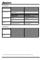
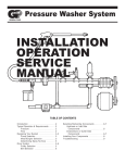
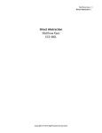
Section
10
Maintenance & Lubrication
Logstacker
80-683
1
General .................................................................................................................................. 3
Safety Precautions ............................................................................................................... 3
Preventive Maintenance ...................................................................................................... 3
Benefits of Preventive Maintenance ...................................................................... 4
Establishing a PM Program .................................................................................. 4
Maintenance Record Keeping ................................................................................ 4
Shift Maintenance Checklist .................................................................................. 4
Using the Checklist ................................................................................................ 4
Scheduled Maintenance ...................................................................................................... 4
Scheduled Maintenance Checklist ........................................................................ 5
Using the Checklist ................................................................................................ 5
Scheduled Oil Sampling ....................................................................................... 5
Daily Maintenance & Lubrication .......................................................................... 6
Pressurized Axle (Optional) ................................................................................... 6
Lubrication Points ................................................................................................................ 8
Service Maintenance Check Lists ....................................................................................... 9
General .................................................................................................................. 13
Before Starting Engine ......................................................................................... 13
Operator Troubleshooting.................................................................................................... 15
Maintenance Specifications .................................................................................. 17
Wheel Nut Torque .................................................................................................. 17
Tire Inflation Pressure .......................................................................................... 17
Lubricant Selection and Specifications .............................................................................. 17
2
80-683
Section
10
Maintenance and Lubrication
General
Machines receiving regular care from its operators and mechanics generally has decreased downtime and greater
reliability. Information in this section provides guidance to
keep the Log Stacker running at top operating efficiency.
Procedures provided in this section can be performed with
a standard shop tools.
Safety Precautions
The following safety precautions are included for your protection. Read them carefully prior to performing any maintenance and lubrication procedures.
1.
Read This Manual.
Be sure you understand the procedures outlined in
this manual prior to performing any machine service
or maintenance. Pay particular attention to any safety
warnings presented. Don’t hesitate to ask an Allied
Systems Company Representitive if there are any
questions.
2.
Perform Maintenance on Level Ground.
The machine should be on level ground and working
or moving equipment whenever possible. The parking brake should be set and the wheels blocked.
Figure 5-1: Typical Swivel Locking Pin Location
3.
Remove Load.
The machine should be unloaded, with the carriage
on the ground.
WARNING: Never rely on the hydraulics to support any part of the machine during maintenance or lubrication. If necessary, support
components with appropriate safety stands.
NEVER stand under a component that is supported only by the hydraulics. Make sure it is
resting on its mechanical stops or safety
stands.
4.
5.
Four Wheel Drive: Install Swivel Locking Pin.
All four wheel drive units are equipped with swivel
locking pins. Always install pin when working in the
area of the swivel hinge. The machine must be on a
level surface. The swivel locking pin can be installed
with the bogie turned right or left.
Stop the Engine.
Before performing any maintenance or lubrication,
remove the key from the switch, and tag the key
swtich with “DO NOT START” to ensure the engine is
not inadvertently started.
Before performing any maintenance or lubrication, remove the key from the switch, and
tag the key switch ”DO NOT START”, to ensure
that the engine is not inadvertently started.
6.
Use Safe Ladders/Scaffolding.
It is essential that safe ladders, personnel lifts and/
or scaffolding be used while servicing upper lubrication points. These areas can be dangerously slippery
in wet, frosty or oily conditions.
Preventive Maintenance
Preventive maintenance is necessary to prevent premature equipment failure. The preventive maintenance system is based on a series of maintenance checks and servicing points. To be effective, the program demands strict
adherence to a planned schedule.
NOTE: Never operate the unit with the locking pins in
the locked position. Damage to the machine could result.
80-683
3
Benefits of Preventive Maintenance
There are several benefits to a good preventive maintenance program. Some benefits include:
•
Promotes Safety - equipment operates more efficiently
and is more responsive to operator control.
•
Improves Equipment Availability - equipment downtime is minimized saving money and increasing productivity.
•
Reduces Unexpected Downtime - helps avoid operating equipment destruction by replacing or rebuilding
parts before they fail.
•
Allows Planning of Daily Production - by knowing
the condition of available equipment.
•
Allows Planning of Maintenance Man Hours - by
distributing duties and necessary lead time for parts
ordering.
•
Provides Complete History of Equipment - based
on performance, frequency and type of repairs and
actual labor hours spent on maintenance.
ished lubricants and hydraulic pressure readings should
be recorded on the schedule form. Record all discrepancies regardless of their status (i.e. whether remedied or
pending). Operators and mechanics should sign off forms
and return them to the maintenance supervisor for approval
and retention in an equipment unit file.
Accurately recorded maintenance forms give maintenance
personnel an overall view of how equipment is performing
under normal operating conditions. Good, easy to review
records enable maintenance personnel to identify and
evaluate problem areas and allow adjustment in the maintenance scheduling as required.
Shift Maintenance
Establishing a Preventive Maintenance Program
The key to an effective preventive maintenance program
is diligence in following a maintenance schedule set at
regular planned intervals. Such intervals should be made
compatible with the nature of operation of the equipment
and with the capabilities of the maintenance facility. In
any event, the intervals and inspection requirements must
be planned, regular, and consistent.
Specific maintenance should be completed using the following intervals:
•
•
•
•
•
•
10 hours (each shift or daily)
50 hours (weekly)
250 hours (monthly)
500 hours (quarterly)
1000 hours (semiannually)
2500 hours (annually)
Each successive schedule (e.g. weekly, monthly, quarterly,
etc.) encompasses the former and is accumulative in nature. For example, when performing monthly maintenance,
take note of the shift maintenance reports and remedy
any discrepancy; then comply with the shift and weekly
maintenance, and in addition perform the checks specified in the monthly schedule.
Maintenance Record Keeping
Check off each scheduled maintenance form as the inspection and service is performed. Quantities of replen4
Shift maintenance records are the building blocks of a preventive maintenance program and are usually completed
by the operator. It consists of the routine (daily and weekly)
servicing and lubrication of the major systems. On a daily
basis, the operator should identify, remedy and/or record
potential problem areas and recognize any change in the
performance of the machine. Comments recorded on the
shift maintenance report are a valuable tool to the maintenance department, and is important to the overall success of a preventive maintenance program.
Shift Maintenance Checklist
A recommended checklist is provided as an aid in developing a practical shift maintenance program. A shift maintenance report, based on this checklist, should be used to
report defects found when making maintenance checks at
the beginning of each shift.
Using the Checklist
The reference numbers in the left-hand column of the checklist indicate the physical location of each check point or
lubrication point as it appears on the shift maintenance
diagram. Circled reference numbers on the diagram indicate lubrication points. Boxed numbers indicate maintenance checkpoints.
Shift maintenance details are provided in the service maintenance check list.These procedures consist of checks
easily performed by the operator.
Scheduled Maintenance
Periodic scheduled maintenance should be performed in a
well-equipped maintenance facility by trained mechanics.
The timely scheduling and completion of these periodic
inspections by the maintenance department determine the
length of machine downtime. Therefore, maintenance
scheduling relies on a critical balance in the use of labor
hours and the availability of equipment.
80-683
Section
Scheduled Maintenance Checklist
A machine’s operating environment affects the maintenance
schedule. More frequent checks are required for machines
operating in severe conditions, like heavy dust, extreme
temperatures or extremely heavy loads.
These maintenance checklists are designed as a guide
until adequate experience is obtained in establishing a
schedule to meet your specific needs and operating environment.
A detailed list of component checks is provided with a
suggested schedule basis given in hours of operation, or
calendar time.
The engine manufacturer’s operation and maintenance
manual should be consulted and adhered to for additional
engine related checks and/or maintenance details.
Establish a maintenance schedule using these checklists
as a guide.
10
Using the Checklist
Although specific maintenance is identified in these checklists, location and procedure references are not provided
in the columns.
Scheduled maintenance is normally performed by trained
mechanics, who are knowledgeable of the equipment systems and component locations. Scheduled maintenance
procedures can be found by referring to the appropriate
section of the service manual.
Scheduled Oil Sampling
Use scheduled oil sampling (SOS) to monitor machine
condition and maintenance requirements. Take oil samples
from engine, transmission, axles, and hydraulic system
when the oil is hot and well mixed to ensure an accurate
analysis. Contact an Allied Systems Company Representative for complete information and assistance in establishing a scheduled oil sampling analysis program for your
equipment.
CAUTION
Failure to adhere to adhere to manufacturer’s
suggested maintenance schedules may result
in loss of warranty coverage.
80-683
5
Daily Maintenance & Lubrication
The chart below includes all points referenced in the Daily
Maintenance and Lubrication Check List shown on the
following page.
Circled Numbers Indicate Lubrication Points
The height of the upper lube points and maintenance check points make it essential that safe
ladders and/or scaffolding be used while servicing the machine. These areas can be dangerously slippery under wet, frosty, icy, snowy
or oily conditions.
Boxed Numbers Indicate Maintenance Check
Pressurized Axle (Optional)
Points
Note: Due to variations in engine types and models,
the indicated location of engine filters (fuel, oil, coolant, etc.) are not shown. Consult your engine service
manual for exact locations.
Some machines have pressurized front axle
housings with 3 psi pressure. Shut off air supply to the axle, then open air drain cock located
on axle housing bulkhead before checking axle
oil level.
Figure 5-2b: Daily Maintenance and Service Check Points, Typical Four-Wheel Drive Machine
6
80-683
Section
10
Figure 5-2a: Daily Maintenance and Service Check Points, Typical Two-Wheel Drive Machine
80-683
7
Lubrication Points
DAILY/EACH SHIFT
Before Engine Startup, Check the Following
Item
No. of Fittings
1
Steering Cylinder Pins
4
22
Boom to Chassis Pins
2
52
Boom to Carriage Pins*
3
25 & 51
Hoist Cylinder Pins*
4
17
Hinge Bearings *
2
50 HOURS OR WEEKLY
20 & 28
Tilt Cylinder Pins
4
33
Holddown arm pins
2
32
Kickoff arm pins
2
27 & 34
Holddown Cylinder Pins
4
26 & 29
Kickoff cylinder pins
4
30
Auxiliary holddown arm pins
2
31 & 53
Auxiliary holddown cylinder pin
4
37
Swivel Bearing
*b
1
41
Front and rear support bearings
*b
2
13
Driveline - converter to transmission
*a
3
14
Driveline - transmission to front axle
*a
3
48
Driveline - transmission to front support bearing
*a*b
3
47
Driveline - front support to mid support
*a*b
3
43
Driveline - mid support to rear support
*a*b
3
40
Driveline - rear support to hinge
*a*b
3
38
Driveline - hinge to rear axle
*a*b
3
250 HOURS
33
Fan Drive Bearing (Not on all engines)
1
500 HOURS
30
Tailwheel bearing
*c
2
29
Tailpost
*c
1
* When operating in water, lubricate submerged points more frequently
*a Use handgun or low pressure adapter; lubricate sparingly
*b Four wheel drive units only
*c Two wheel drive units only
8
80-683
Section
10
Service Maintenance Check Lists
Daily/Each Shift
Item
OK
No
5
____
_____
________
11 HYDRAULIC TANK (Check oil level - check for leaks)
____
_____
________
2 RADIATOR (Check coolant level - check for leaks)
____
_____
________
19 AIR CLEANER (Check indicator - clean or change element as req’d
____
_____
________
19 AIR INTAKE SYSTEM (Check for leaks and damage)
____
_____
________
42 ENGINE BELTS (Check for adjustment and wear)
____
_____
________
8
AIR TANKS (Check drain valves for correct operation
____
_____
________
2
RADIATOR & OIL COOLER (Are fins clean and unobstructed?)
____
_____
________
____
_____
________
____
_____
________
- - LUBRICATE CHASSIS (Refer to lube chart)
____
_____
________
- - ENGINE (Does it sound normal?)
____
_____
________
31
8
ENGINE (Check Oil Level -check for leaks)
50
WHEELS & TIRES (Check condition and pressure)
HYDRAULIC BRAKE FLUID (Check fluid level - if so equipped)
Add/Repair
After Starting the Engine, Check the Following
3
INSTRUMENTS (Check for normal readings)
____
_____
________
15 CONTROLS (Check for normal operation)
____
_____
________
12 EXHAUST SYSTEM (Check for leaks and excessive emissions
____
_____
________
19 TRANSMISSION (Check oil level - check for leaks)
____
_____
________
Note Anything Abnormal Or In Need Of Repair
LIGHTS _________________________________
DEFROSTER _____________________________
HORN __________________________________ REVERSE WARNING HORN __________________
WINDSHIELD WIPERS _________ HEATER _____________________
_______________________
AIR CONDITIONER ____________ ___________________________
_______________________
OPERATOR __________________ SUPERVISOR _______________
MODEL ______________________ SERIAL NUMBER ____________
80-683
DATE __________________
HOUR METER ___________
9
Service Maintenance Check Lists
50 HOURS OR WEEKLY
Item
OK
No
Add/Repair
1. Repeat daily maintenance & lubrication check list
____
_____
________
2. Check for fluid leaks (oil, fuel and water) and correct
____
_____
________
3. Check brakes for adjustment and wear
____
_____
________
4. Check wheel lug nuts and studs mechanically, Torque to Spec
____
_____
________
5. Record engine RPM (at idle, high free idle and converter stall)
____
_____
________
6. Empty dust cap bowl on air filter
____
_____
________
7. Check transmission oil level (at operating temperature)
____
_____
________
8. Check battery electrolyte level
____
_____
________
____
_____
________
OK
No
1. Repeat 50 hour check
____
_____
________
2. Take engine oil sample for analysis *
____
_____
________
3. Change engine oil and all filters *
____
_____
________
4. Check axle differential and planetary oil level
____
_____
________
5. Change cooling system filter (if so equipped)
____
_____
________
6. Check all hydraulic pressures and record (see hydraulic schematic)
____
_____
________
7. Check fire suppression system (if so equipped)
____
_____
________
8. Check disc brake calipers, pads, rotors and lines (if so equipped)
____
_____
________
9. Grease all non-Lube-For-Life drivelines
____
_____
________
10. Check and adjust the parking brake (if required)
____
_____
________
9. Visually check for structural damage (inspect chassis & attachments
for indication of fatigue or damage)
250 HOURS OR MONTHLY
Item
Add/Repair
IMPORTANT: Consult the engine manufacturer’s Operation and Maintenance Manual for additional
engine related checks and/or details.
10
80-683
Section
10
Service Maintenance Check Lists
500 HOURS OR QUARTERLY
Item
OK
No
Add/Repair
1. Repeat 250 hour check
____
_____
________
2. Take oil samples of transmission, axle and hydraulic systems *
____
_____
________
3. Drain and refill transmission, change filter *
____
_____
________
4. Service fuel filters per manufacturer’s recommendation *
____
_____
________
5. Service hydraulic filters *
____
_____
________
6. Inspect brake systems & components
____
_____
________
1000 HOURS OR SEMI-ANNUALLY
Item
OK
No
Add/Repair
1. Repeat 500 hour check
____
_____
________
2. Clean and flush cooling system
____
_____
________
3. Check pins and bushings for excess wear
____
_____
________
4. Drain, flush and refill differentials *
____
_____
________
5. Drain, flush and refill planetaries *
____
_____
________
OK
No
1. Repeat 1000 hour check
____
_____
2. Check and recharge accumulators, record pressure (if so equipped)
____
_____
________
3. Replace hoses as required, steam clean engine, tighten
mounting bolts and turbocharger mounting bolts
____
_____
________
4. Drain hydraulic tank, flush tank and refill
____
_____
________
5. Change hydraulic oil and filters *
____
_____
________
2500 HOURS OR ANNUALLY
Item
Add/Repair
* Normal drain period and filter change intervals are for average environmental and duty-cycle conditions. Severe or sustained
high operating temperatures or very dusty atmospheric conditions will cause accelerated deterioration and contamination.
Change intervals should be adjusted according to the results of oil sampling analysis. Consult your Wagner dealer for
assistance in establishing an oil sampling program for your equipment.
IMPORTANT: Consult the engine manufacturer’s Operation and Maintenance Manual for additional
engine related checks and/or details.
80-683
11
Service Maintenance Check Lists
Repairs
Problem: ____________________________________________________________________________
___________________________________________________________________________________
___________________________________________________________________________________
___________________________________________________________________________________
___________________________________________________________________________________
___________________________________________________________________________________
Parts: _______________________________________________________________________________
___________________________________________________________________________________
___________________________________________________________________________________
___________________________________________________________________________________
___________________________________________________________________________________
___________________________________________________________________________________
Mechanic: _____________________________________________________ Hours Labor: _________
Operator: ________________________________
Supervisor: _______________________________
Machine Model ___________________________
Equipment No: ____________________________
Date: ________________________ Shift: _______________________ Hour Meter: ______________
12
80-683
Section
Maintenance Procedures
General
Perform the following maintenance procedures at the beginning of each work shift. The number before each maintenance procedure corresponds with the numbers given in
the Daily Maintenance and Service Check Points (Fig. 52). This provides an additional aid in locating each check
point.
Before Starting Engine
5
Engine Oil Level
Check the oil level prior to starting the engine. Make
sure that the area around the dipstick is clean and
the machine is sitting on level ground.
NOTE: A 15-minute drain-back time is recommended is the engine has been running.
The oil level must be maintained between the “L” (low)
mark and the “H” (high) mark, but as close to the “H”
mark as possible.
CAUTION
CAUTION: Never operate the engine with the
oil level below the “L” mark or above the “H”
mark. Refer to the engine’s Operation and Maintenance Manual for detailed engine service information.
Use only approved engine oil (see Lubricant
Specifications, page 5-14). Do not overfill.
Check engine for leaks.
11
Hydraulic Oil Level
Always check the hydraulic oil level prior to operation. The dipstick and fill pipe are located on the RH
chassis deck, to the right of the operator’s cab.
CAUTION
CAUTION: Always open the tank breather petcock (located on the breather pipe) before removing the dipstick, filler cap or in-tank filter
cover plate. Failure to vent the tank can result
in injury or a substantial oil spill. Be sure to
close the petcock before operating the machine.
Check the oil level with the hoist cylinders retracted
(down). The oil level should be at or near the “H” (high)
mark on the dipstick. Fill with approved hydraulic fluid
80-683
10
as required (see Lubricant Specifications). Do not
overfill.
3
Engine Coolant Level
Daily inspection of the coolant level is recommended.
Cooling systems using anti-aeration baffles restrict
visual observation of the true coolant level. Although
the coolant can be seen, the system may not be full.
To gain a true fill, add water slowly up to the bottom
of the fill neck and allow a 30-second settling period.
Remember to compensate for the loss of anti-freeze
when adding water.
Never remove the radiator cap if the engine is
hot. The coolant will be under pressure and
could flash to steam with explosive force, causing severe burns. Remove the readiator cap
only when the engine is cool.
NOTE: If the engine is hot, the coolant level will
be higher than when it is cold.
Inspect the radiator daily for restrictions caused by
leaves, dust, paper or bent fins. Inspect the radiator
cap, hoses and connectors for any signs of leakage
or damage.
19 Air Cleaner
The air cleaner is a cyclonic-type, dry air filter. A service indicator shows the condition of the filter. The
indicator will show in the green zone when the filter
is clean. The indicator will show red when the filter is
restricted. If red appears in the indicator window,
change the primary element and press the reset button on the indicator. Check the safety element and
change as required.
42 Engine Belts
Check the tension of the drive belts by pressing with
the thumb halfway between the pulleys. The belt
should not deflect more than the values shown in the
table (Fig. 5-3). If any belt is loose or worn, report to
maintenance for corrective action.
Engine
Cummins
Caterpillar
Belt Deflection Inches (mm)
3/8 to 5/8 (9.5 to 15.9)
1/2 to 3/4 (13 to 19)
Figure 5-3: Engine Belt Deflection
13
8
Air Tank Valves (If Applicable)
Visually inspect the valves and connections for damage or leaks. There should be signs of water coming
from the drain hoses. If not, report the condition to
maintenance.
35 50 Wheels and Tires
Visually inspect the tires for low air pressure and
damage. Also check the wheel assemblies for cracks,
loose or missing lug nuts, borken studs, etc.
16
Hydraulic Brake Fluid
Check the fluid level in each of the two brake
reserviors. Each reservoir must be full. Clean the
area around the filler cap before removing. Fill the
reservoirs with transmission fluid. Do not use automotive brake fluid.
After Starting the Engine
5
Engine
After starting, check that the engine runs and sounds
normal. It should come up to operating temperature
within a few minutes after starting. If you notice unusual noises, leaks or excessive smoke, shut down
the engine and immediately ocntact maintenance.
3
Instruments
Check all the instruments for normal readings immediately after starting the engine. Make sure that temperatures are within acceptable limits. Also, check
that all controls function properly. They should be
smooth and responsive.
14
14
Air Intake System
Inspect all connections for damage and air leaks. Look
for damaged fittings and loose connections. Do not
operate the machine if leaks are present. Dirt could
enter the engine through the intake and cause severe damage.
1
Exhaust System
Check for exhaust leaks. Make sure that exhaust
gases are not entering the operator’s cab. Mounting
brackets must be in place and all connections tight.
Check for excessive smoke.
2
Transmission Oil Level
The level should be checked after engine warm-up,
with 180° to 200° showing on the transmission temperature guage. The dipstick and fill tubes are located
on the chassis deck, directly above the transmission. Check the level with th engine running at idle, at
operating temperature, and with the transmission in
neutral. The level should be between the “H” (high)
and “L” (low) marks. Fill with approved fluid only. See
Lubricant Specifications on page 5-14. Do not overfill. Inspect for leaks.
80-683
Section
10
Operator Troubleshooting
The following tables list the most common problems that
may be encountered by operators. If the problem cannot
be solved using the corrective actions listed in this table,
notify maintenance personnel.
Engine*
Symptom
Probable Cause
Engine turns over but fails Fuel Solenoid not energized or is faulty
to start
Fuel Tank empty
Fuel shutoff valve at tank closed
Fuel filter blocked
Engine Fails to turn over Battery disconnect switches open
Transmission not in neutral
Low battery condition
Battery terminals corroded or loose
Insufficient fuel supply
Engine runs unsteadily
and power output is low
Air leak into fuel system
Contaminated fuel
Exhaust smokes badly
Engine overheats
Engine oil pressure low
Incorrect fuel
Air intake restricted
Too much oil in sump
Air intake restricted
Restricted airflow through radiator
Low coolant level
Low oil level
Oil leaks
Contaminated oil
Corrective Action
Replace fuel solenoid
Fill Tank
Open Valve
Replace filter
Close Switches
Place lever in neutral
Check charge system
Clean and tighten terminals
Clean fuel strainers, replace filter, fill
tank,tighten fuel lines
Clean fuel strainers, replace filter, fill
tank,tighten fuel lines
Drain tank and lines, clean strainers,
replace fuel
Drain tank and fill with proper fuel
remove restriction
Drain to proper level
Remove restriction
Clean fins
Check coolant level, fill as needed
Check oil level
Tighten connections, Correct as required
Change oil and filters
Transmission/ Converter*
Probable Cause
Symptom
Transmission or converter Low oil level
overheats
High oil level
Restricted airflow for oil cooler
Lack of Power
Low engine RPM at converter stall
High engine RPM at converter stall
Failing charge pump
Corrective Action
Fill to proper level
Remove excess oil
Remove restriction
Check engine (governor)
Check engine (governor)
Check torque converter
Wet Disc Brake System (If Applicable)*
Probable Cause
Loss of oil pressure - refer to service
manual
Loss of braking efficiency - Air in hydraulic brake system
Refer to Service Manual Loss of accumulator pressure
Low system pressure
Symptom
Brakes won't release
*
Corrective Action
Troubleshoot as required
Check the pump
Troubleshoot as required
Wait for system to recharge
Also refer to the manufacturer’s Operation and Maintenance Manual for additional information
80-683
15
Hydraulic System*
Symptom
No response to controls
Sluggish operation or
response to controls
Excessive pump noise
Hydraulic system
overheating
Probable Cause
Closed control shutoff valve
Low oil level
Failed pilot pump/relief
Hydraulic oil cold
low oil level
Suction leak
Plugged tank breather
Restriction in circuit
Pump damaged/failing
Cavitation
Corrective Action
Open valve
Fill tank to proper level
Replace pump or relief
Allow adequate warm-up time
Aeration due to insufficient oil/poor oil
quality
Low oil level
Operating over pressure relief or
excessive system leakage
Fill tank to proper level
Correct suction leak
Replace breather
Remove restriction, check filter
Check engine speed
Eliminate restriction in suction line, replace
tank breather
Fill tank to proper level, correct suction
leak
Fill tank to proper level
Correct operating procedure, or replace
system components
Probable Cause
Battery disconnect switches open
Neutral start switch open
Battery low
Battery terminals corroded or loose
Other connections loose
Alternator drive belt slipping or broken
Loose or corroded battery connections
Defective alternator or battery
Corrective Action
Close switches
Place transmission shift lever in neutral
Test charge system
Clean/tighten terminals
Tighten connections
Tighten or replace belt
Clean/tighten terminals
Replace battery and/or alternator
Electrical System*
Symptom
Engine fails to turn over
Voltmeter indicates
discharge
*
16
Also refer to the manufacturer’s Operation and Maintenance Manual for additional information
80-683
Section
10
Maintenance Specifications
Most of the required maintenance specifications, such as
the hydraulic pressure relief settings, can be obtained from
the Service Manual and the hydraulic schematic.
Note: Set Hydraulic pressures at 1500 rpm. Override
should not be over 50-100 psi on control valves. Check
or set pressures after hydraulic oil is above 100° F with
calibrated gauges.
Wheel Nut Torque
Wheel nut torque for specific machines is located in the
service manual under Section 3-5, wheels and tires.
Tire Inflation Pressure
Tire inflation pressure for specific machines is located in
the service manual under Section 3-5, wheels and tires.
Lubricant Selection and Specifications
The efficiency and useful life of mechanical equipment is
as dependent on proper lubrication as on proper engineering design. The importance of proper lubrication is
increased because of the greater loads and pressures
imposed on present day mobile heavy equipment. For
this reason, we are vitally interested in promoting widespread usage of the best possible lubricants for Allied
Systems Company products.
have given excellent results in a wide range of operating
conditions. In all cases, the lubricant supplier assumes
all responsibility for the performance of his product and for
product liability.
Allied Systems Company requires that lubricants meet, or
exceed, the specifications of the oils listed above to avoid
component failure and to qualify for warranty consideration.
Our suggested lubrication and selection and specification list is located in section 10-1 of the service
manual. If a cross reference to Mobil Oil Corporation
specifications is required, please consult your local lubricant dealer.
When changing fluids use the following guidelines:
• Add only filtered fluids.
• It is important to service filters and breathers at
the proper hourly intervals.
• If adding lubricants other than what is currently in
the reservoir, a warranty of compatibility should be
obtained from the oil supplier.
• When the fluid is changed due to changes in
ambient temperatures, the system should be completely drained and the fluid replaced.
Because many brands of fluid are available, it is not practical to test each one. Selecting the correct fluid should
be done with the help of a reputable oil supplier who is
responsible for the quality of the fluid. Our lubricant recommendations are based on commercial products that
80-683
17