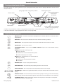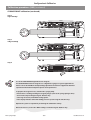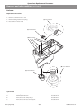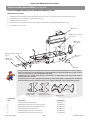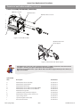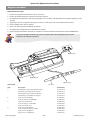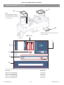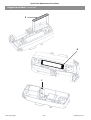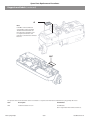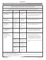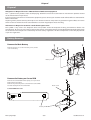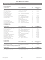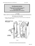
1
Alaris Syringe Pumps ® Technical Service Manual This manual has been prepared for use by qualified service personnel only. Cardinal Health cannot accept any liability for any breakdown or deterioration in performance of parts or equipment resulting from unauthorised repair or modification. t Cardinal Health, 1180 Rolle, Switzerland Alaris®, Guardrails® and Asena® are registered trademarks of Cardinal Health, Inc. or one of its subsidiaries. All other trademarks belong to their respective owners. © 2002-2007. Cardinal Health, Inc. or one of its subsidiaries. All rights reserved. Alaris® Syringe Pumps 2/89 1000SM00001 Issue 10 Contents Chapter 1. General Information 4 2. Configuration & Calibration 9 3. Routine Maintenance 21 4. Troubleshooting 30 5. Circuit Descriptions 37 6. Spare Part Replacement Procedures 40 Appendix Alaris® Syringe Pumps A. Specifications 62 B. Disposal 69 C. Spare Parts Listing 71 D. Fitting & Replacement Guidelines 76 E. Configuration & Drug Protocol Records 79 F. Service Contacts 86 G. Document History 88 3/89 1000SM00001 Issue 10 Chapter 1 General Information In this chapter Introduction 5 General precautions 5 Front panel and main display 6 Controls and indicators 6 Loading a syringe 7 Starting the pump 8 Basic features 8 General Information Introduction The Alaris® Syringe Pumps are designed to deliver a continuous and accurate infusion whenever small fluid volumes need to be administered with great precision. High performance, comprehensive alarm protection and sophisticated monitoring systems combined with simple operation make these syringe pumps suitable for both general and critical infusions in a variety of areas within a hospital. The Asena® brand name has been recently changed to the Alaris® brand name. This change in brand name has no effect on the intended use or functionality of the product. Recommended disposable products for use with this product may refer to either the Asena® brand name or Alaris® brand name and both types are suitable for use with this infusion pump. Familiarity Ensure that you are fully familiar with this syringe pump by carefully studying the Directions for Use (DFU) prior to attempting any repairs or servicing. As part of a policy of continuous improvement, product enhancements and changes are introduced from time to time. Purpose This Technical Service Manual shows how to set up, test and maintain the following Alaris® Syringe Pump models: Alaris® GH Syringe Pump Alaris® GH Syringe Pump with Guardrails® Safety Software Alaris® CC Syringe Pump Alaris® CC Syringe Pump with Guardrails® Safety Software Alaris® PK Syringe Pump Alaris® TIVA Syringe Pump Alaris® GS Syringe Pump It is intended for use by personnel experienced in medical equipment testing and maintenance procedures. Symbols Wherever you see this symbol in the manual you will find a Hints & Tips note that we hope you will find useful. These notes provide useful advice or information that may help you perform the task more effectively. Wherever you see this symbol in the manual you will find a Toolbox note that highlights an aspect of test or maintenance that is important for you to know about. A typical example is a software upgrade that you should check has been installed. General precautions w Please read the general Operating Precautions described in the Directions for Use carefully prior to using the pump. This pump contains static-sensitive components. Observe strict precautions for the protection of static sensitive components when attempting to repair and service the pump. B A An explosion hazard exists if the pump is used in the presence of flammable anaesthetics. Exercise care to locate the pump away from any such hazardous sources. M This pump is protected against the effects of high energy radio frequency emissions and is designed to fail safe if extremely high levels of interference are encountered. Should false alarm conditions be encountered, either remove the source of the interference or regulate the infusion by another appropriate means. L Alaris® Syringe Pumps An electrical shock hazard exists if the pumps casing is opened or removed. Refer all servicing to qualified service personnel. If the pump is dropped, subjected to excessive moisture, humidity or high temperature, or otherwise suspected to have been damaged, remove it from service for inspection by qualified service personnel. When connected to an external power source, a three-wire (Live, Neutral, Earth) supply must be used. If the integrity of the external protective conductor in the installation or its arrangement is in doubt, the pump should be operated from the battery. 5/89 1000SM00001 Issue 10 General Information Front panel and main display The display shown is for general guidance only. For pump specific front panel and main display information refer to relevant Directions For Use. Syringe Type Fitted / Drug Name / Profile* Time Remaining Icon Pressure Information** / Pressure Icon (if enabled) Infusion Status Infusion Rate Volume Infused Blank Softkeys Pressure button (not available on the Alaris® GS Syringe Pump) * “Profile” is only available on an Alaris® Syringe Pump with Guardrails® Safety Software with a Data Set loaded. ** Pressure Information is only displayed on the Alaris® CC Syringe Pump. Controls and indicators a b h c i ON/OFF button - Press once to switch the pump ON. Press and hold down for 3 seconds to switch the pump OFF. RUN button - Press to start the infusion. The Green LED will flash during infusion. HOLD button - Press to put the infusion on hold. The amber LED will be lit while on hold. MUTE button - Press to silence alarms. PURGE/BOLUS button - Press to access PURGE or BOLUS soft keys. Press and hold down soft key to operate. PURGE the extension set during set up. Pump is on hold Extension set is not connected to the patient Volume Infused (VI) is not added BOLUS fluid or drug delivered at an accelerated rate. Pump is infusing Extension set is connected to the patient VI is added d e g f j k Alaris® Syringe Pumps OPTION button - Press to access optional features. PRESSURE button - Press to display the pumping pressure and alarm level. BLANK SOFTKEYS - Use in conjunction with the prompts shown on the display. CHEVRON keys - Double or single for faster/slower, increase or decrease of values shown on main display. BATTERY indicator - When illuminated, indicates that the pump is running on the internal battery. When flashing, indicates that the battery power is low, with less than 30 minutes of use remaining. AC POWER indicator - When illuminated, indicates that the pump is connected to an AC power supply and the battery is being charged. 6/89 1000SM00001 Issue 10 General Information Loading a syringe 1. Squeeze the finger grips together on the plunger holder and slide the mechanism to the right. Pull the syringe clamp forward and down. 2. Place the syringe barrel flange in the slot between the two blue sections of the syringe flange clamp. Note: Earlier pumps have a single section syringe flange clamp. In this instance place the syringe barrel flange in the space between the syringe clamp and the syringe flange clamp. Syringe flange clamp To ensure the syringe is loaded correctly, check the syringe remains in position before the syringe clamp is closed. Syringe clamp 3. Lift the syringe clamp until it locks against the syringe barrel. 4. Squeeze the finger grips on the plunger holder and slide the mechanism to the left until it reaches the plunger end. 5. Release the finger grips. Ensure that the plunger grippers are securing the plunger in place and the upper finger grip returns to its original position. Upper finger grip Ensure that both plunger grippers are fully locked onto the plunger flange and the upper finger grip has returned to its original position. Guide to handling the pressure disc Pressure Disc Inserting the Pressure Disc Pressure Transducer Withdrawing the Pressure Disc When withdrawing the pressure disc, make sure you pull it (with your finger inside the disc recess) towards the front of the pump as shown in the diagram above. Alaris® Syringe Pumps 7/89 1000SM00001 Issue 10 General Information Starting the pump 1. Push pump on to bar, the Alaris® Docking Station or mount to pole. Connect to AC Mains. 2. Press the a button to switch pump ON. 3. Follow SETUP / Drug / Profile instructions as per Directions For Use. 4. Load syringe. 5. Insert pressure disc into pressure transducer (Model CC only, required for dedicated mode). 6. Confirm syringe. 7. Change the rate if necessary using the f keys. 8. Purge: Press the i button followed by the PURGE softkey. 9. Connect the pump to test equipment as required (see chapter 2 Configuration & Calibration). 10. Press the b button to start the infusion. Basic features Pressure Level (not available on Model GS) Press the e button. Pressure Alarm level and current pressure level are shown on graph. Use the f keys to adjust pressure alarm level. Volume to be Infused (not available on Models TIVA & GS) Press VTBI. Enter VTBI using the f keys. Press OK. Select rate at end of VTBI using the f keys. Press OK. Clear Volume Infused Press VOLUME. Select YES (to clear) or NO (to exit). Purge/Bolus Press the i button, use the f keys to set rate, then press and hold down the PURGE or BOLUS softkey. Hands-free Bolus* (Model TIVA only) Press the i button, if required, select HANDSFREE BOLUS, use the f keys to adjust bolus dose. Use rate softkey to adjust bolus rate if required. Press BOLUS softkey to deliver. During PURGE/BOLUS, the pressure limit alarms are temporarily increased to maximum levels. Option Button d Drug Library* Select Drugs and Dosing (Models CC & TIVA) or Drug name (Model GH). Set VTBI Over Time 24 Hour Log Specify a VTBI and delivery time (not available on Models TIVA & GS). Pump must be on hold. Volume infused log over 24 hours and accumulative total (on the hour only). Rate Lock Disables changing rate once infusion has started (not available on Model TIVA). When rate lock is enabled, the following are unavailable: 1. Rate changes/titration 2. Bolus/Purge 3. Switch pump off Event Log* Hospital Name* Access Event Log. The Event Log holds up to 1500 individual events. Pumps with Guardrails® Software enabled retain one year of events. Displays the name of Hospital/Ward/Department as set up on the pump. Accessible while the pump is infusing. Additional options may be shown, please refer to the relevant Directions For Use, for more information. * Note: For Guardrails® Software enabled pumps or the Alaris® PK Syringe Pump these options may vary or will not be available. Please refer to the relevant Alaris® Syringe Pump Directions For Use or Guardrails® Editor Directions For Use for comprehensive information. Alaris® Syringe Pumps 8/89 1000SM00001 Issue 10 Chapter 2 Configuration & Calibration In this chapter Access codes 10 Dedication options (301/302) 10 Data Set Activation (612) 10 Handsfree Bolus (175) 10 Power Lock (711) 10 Configuration options (251) 11 Calibration procedures (243) 15 Configuration & Calibration Access codes The syringe pump software contains a number of configuration and test routines that can be accessed by the user. The majority of tests are ‘MENU’ driven from a technical access code (see below). Code Description 123 Self Test Procedure 166 External Reprogramming 167 Teach Learn Procedure 175 Handsfree Bolus 243 Calibration Selection Menu 251 User Configuration Menu 301 Fully Dedicated 302 Semi-dedicated 376 Service Access Menu 401 Upload Data Set to Pump (Guardrails® Software enabled Pumps and the Alaris® PK Syringe Pump) 402 Download CQI Event Log from Pump (Guardrails® Software enabled Pumps only) 418 Alternative Alarm Tone. (Not available for Guardrails® Software enabled Pumps & the Alaris® PK Syringe Pump) 499 Download Data Set from Pump (Guardrails® Software enabled Pumps and the Alaris® PK Syringe Pump) 611 Cold Start (RAM Clear) 612 Data Set activitation (Alaris® PK Syringe Pump) 711 Power Lock (Alaris® PK Syringe Pump) Each MENU (and some unique items) has its own three-digit access code that can be entered using the following procedure: 1. Hold down b and turn the pump ON. 2. Enter the required access code using the f keys and the NEXT softkey. 3. When the required code shows on screen, press OK to confirm. Dedication options (301/302) Fully Dedicated (set using access code 301) will remind a user that a pressure disc must be fitted to start any infusion. In this mode occlusion pressures are always displayed in mmHg. Semi-Dedicated (set using access code 302) will remind a user that a pressure disc must be fitted when drugs and dosing features are used. When a pressure disc is not in use, pressure levels L-0 to L-10 will be displayed. Data Set Activation (612) This code is used to load the predefined pump configuration and drug setup into the non-volatile storage. It is necessary to enter the code 612 after a cold start (code 611); the configuration and drug setup will then be available in normal operation. Alternatively a data set may be uploaded as appropriate. See directions for use contained within the Alaris® PK Editor Software package. Handsfree Bolus (175) Enable or disable the Handsfree Bolus. If enabled pressing bolus button displays screen prompting for hands free or hands on. Default volume after clear setup is 0.0. Upper amount restricted to bolus volume limit in general options or drug protocol bolus volume limit. Power Lock (711) Available on the Alaris® PK Syringe Pumps with software V2.3.11 & above. Disabled The new alternative Power Down sequence now allows the user to Power Down the pump whilst the infusion is suspended (on hold) in TCI mode and predictive TIVA mode. Enabled The Power Down sequence (Power Lock) remains the same where the user may only Power Down the pump by stopping the infusion, selecting ‘new operation’ from the options menu, confirming the selection, then Powering Down the pump. Alaris® Syringe Pumps 10/89 1000SM00001 Issue 10 Configuration & Calibration Configuration options (251) Enter access code 251 to display the User Configuration menu: Drug Library* Set drug names list on a Model GH - Select Character Group f Select Character f To go to next Character use NEXT. Set drug names and protocols for Models CC and TIVA (see drug protocol setup instructions on following pages). General Options* See table on the following page. Clock Set Set the current date and time. To set the clock, use f and NEXT to adjust and OK to store. Hospital Name* Enables establishment name (max 20 characters) to be displayed during the power-up sequence. To set the hospital name, use f and NEXT to adjust and OK to store. Enable Syringes* Configure the type and size of syringes permitted for use. To enable syringes, use f and SELECT, to enable/disable and OK to store. Language Configure the language used for messages shown on display. Select language required using f and SELECT to store. Contrast Set the display panel contrast. Use f to adjust contrast and OK to store. Enable Units* Select the type of units permitted for use on the pump. To enable units, use f and MODIFY, to enable/disable and OK to store. * Note: For Guardrails® Software enabled pumps and the Alaris® PK Syringe Pump these options may vary or will not be available. Please refer to the relevant Alaris® Syringe Pump Directions For Use or Guardrails® Editor Directions For Use for comprehensive information. Alaris® Syringe Pumps 11/89 1000SM00001 Issue 10 Configuration & Calibration Configuration options (251) (continued) Alaris® TIVA Syringe Pump drug protocol setup Select Drug Library from Configuration Options (251). Use f to select drug and press MODIFY to modify selected drug or NEW to create new drug name. QUIT will return to 251 main menu. When modifying a drug protocol, pressing BACK at any time will take you to the previous step. Modify - Existing drug ENABLE/DISABLE - Enables or disables the drug being available. DELETE - Select Yes to delete from drug library. EDIT - See table below. Edit Drug Protocol - New or existing drug Press OK softkey to confirm each step. To Adjust Drug Option (Softkeys are shown in Bold) Select Character Group f Select Character f Drug Name To go to next Character NEXT Alaris® Syringe Pumps Concentration Units f Minimum Concentration f or OFF Default Concentration f or OFF Maximum Concentration f or OFF Dose Rate Units f Induction Dose f or OFF Induction Time f Pause After Induction MODIFY Maintenance Rate f Bolus Dose f Bolus Rate RATE Hands Free Bolus MODIFY 12/89 1000SM00001 Issue 10 Configuration & Calibration Configuration options (251) (continued) Alaris® CC Syringe Pump* drug protocol setup Select Drug Library from Configuration Options (251). Use f to select drug and press MODIFY to modify selected drug or NEW to create new drug name. QUIT will return to 251 Main menu. When modifying a drug protocol, pressing BACK at any time will take you to the previous step. Modify - Existing drug ENABLE/DISABLE - Enables or disables the drug being available. DELETE - Select Yes to delete from drug library. EDIT - See table below. Edit Drug Protocol - New or existing drug Press OK softkey to confirm each step. * Note: For Guardrails® Software enabled pumps this option will not be available. Please refer to the relevant Alaris® Syringe Pump Directions For Use or Guardrails® Editor Directions For Use for comprehensive information. To Adjust Drug Option (Softkeys are shown in Bold) Select Character Group f Select Character f Drug Name To go to next Character NEXT Alaris® Syringe Pumps Dose Rate Units f Maximum Dose f or OFF Default Dose f or OFF Minimum Dose f or OFF Concentration Units f Minimum Concentration f or OFF Default Concentration f or OFF Maximum Concentration f or OFF Maximum Bolus f or OFF Bolus Rate f Pressure Alarm f or OFF 13/89 1000SM00001 Issue 10 Configuration & Calibration Configuration options (251) (continued) General options Option Description GS NURSE CALL FITTED Enables Nurse Call (hardware option). NURSE CALL INVERT When enabled, the nurse call output is inverted. RS232 SELECTED Sets the pump’s communications to use RS232 (hardware option). Models GH* CC* TIVA Automatically sets the line occlusion pressure alarm level to a specified amount above the current pressure. Adjusts the automatic offset value used by auto pressure and auto set pressure. HANDS FREE BOLUS Enables / disables hands-free bolus. Sets the maximum pressure limit. CAP PRESSURE NEOI WARNING Sets the Near End Of Infusion (NEOI) warning time. EOI POINT Sets the End Of Infusion volume. KVO AT EOI Enables pump to run at the Keep Vein Open (KVO) rate when End Of Infusion (EOI) is reached. KVO RATE Sets the Keep Vein Open (KVO) rate. BACK OFF Motor will reverse to relieve line pressure when an occlusion occurs. AUTO SAVE When disabled, the patient information is cleared on power up. RATE LOCK When enabled, the rate can be locked to prevent unwanted changes of the set infusion rate. QUIET MODE When enabled, the button beeps are muted. AC FAIL When enabled, the AC Power Failure Alarm will sound if AC power is disconnected. RATE TITRATION When enabled, the rate can be changed whilst the pump is infusing. PRESSURE DISPLAY Enables / disables the Pressure Icon on the main display. AUTO PRESSURE Enables / disables the automatic pressure alarm level option. AUTO SET PRESSURE AUTO OFFSET PRESSURE DEFAULT Sets the default occlusion alarm level. DEFAULT BOLUS VOLUME Sets the default hands-free bolus volume for No Drug mode only. MAX PRESSURE Sets the maximum pressure limit. WEIGHT Sets the default patient weight in kg. CAP RATE Sets the maximum value for infusion rate. PURGE RATE Sets the purge rate. PURGE VOLUME LIMIT Sets the maximum permissible purge volume. PURGE SYRINGE Prompt to purge syringe after confirmation. BOLUS Enables / disables the bolus feature. DEFAULT BOLUS Sets the default bolus rate. CAP BOLUS RATE Sets the maximum value for bolus rate. BOLUS VOL LIMIT Sets the maximum permissible bolus volume. MANUAL BOLUS Volume infused will be increased if plunger is manually moved in and syringe remains confirmed. CALL BACK TIME Adjusts the time for the pump to sound the call back alarm. VTBI CLEAR RATE Rate will be set to zero when VTBI has been set-up with stop as the end rate. EVENT LOG DISPLAY Enables / disables the event log display. BATTERY ICON Enables / Disable the Battery Icon on the main display.** AUDIO VOLUME Sets the alarm volume of the pump at high, medium or low. AUTO NIGHT MODE Sets Backlight to dim between 21:00 and 06:00hrs. Key: = available option = unavailable option Alaris® Syringe Pumps * For Guardrails® Software enabled pumps and the Alaris® PK Syringe Pump these options may vary or will not be available, with only the first three options listed in table above adjustable in the General Options on the pump. Please refer to the relevant Alaris® Syringe Pump Directions For Use or Guardrails® Editor Directions For Use for comprehensive information. ** For Alaris® GS Syringe Pump the battery icon can be seen via the Options menu by pressing the d key. 14/89 1000SM00001 Issue 10 Configuration & Calibration Calibration procedures (243) Enter access code 243 to display the Calibration Selection menu (see Access Codes). SYRINGE CLAMP calibration Fit calibration tool into position on pump as shown in Steps 1-2 and close the clamp. At each step, CAL is displayed if value is within tolerances. Press CAL button to store calibration point. Calibration tool required: 1000TG00095 Note: If CAL is not displayed, check for correct positioning of calibration tool. If calibration cannot be performed, repairs to pump may be necessary. Note: The calibration values shown on the displays are for illustrative use only and may vary. Step 1 Step 2 Step 3 Alaris® Syringe Pumps 15/89 1000SM00001 Issue 10 Configuration & Calibration Calibration procedures (243) (continued) PLUNGER POS (position) calibration Fit calibration tool in position on pump as shown in Steps 1-3. At each step CAL is displayed if value is within tolerance. Press CAL button to store calibration point. Note: If CAL is not displayed, check for correct positioning of calibration tool. If calibration cannot be performed, repairs to pump may be necessary. Note: The calibration values shown on the displays are for illustrative use only and may vary. Calibration tool required: 1000TG00095 Step 1 Channel for locking clip Step 2 Close-up of calibration tool, showing locking clip in position. Step 3 Locking clip Step 4 Alaris® Syringe Pumps 16/89 1000SM00001 Issue 10 Configuration & Calibration Calibration procedures (243) (continued) SYRINGE FORCE calibration Precondition: This preconditions the mechanism and should only be done if motorplate or chassis has been replaced. Fit Calibration tool as shown, zero the gauge, run until gauge registers 10kgf and then carefully declutch mechanism and withdraw plunger. Do not press any button during this procedure. Calibration tool required: 0000TG00200 (top) or 0000TG00020 (bottom) To convert Kilograms of Force (kgf) to Newtons (N) multiply by 9.806650. For example 10kgf = 98.07N. Excessive force will damage the plunger mechanism. Do not apply more than 10 kgf ±0.05kgf to the plunger mechanism at any time. Note: The calibration values shown on the displays are for illustrative use only and may vary. Precondition 10kgf ±0.05kgf Zero Gauge Syringe Force Calibration Tool Plunger Fit Calibration tool and position plunger as shown in Steps 1 to 3, zero the gauge. At each step press CAL when required calibration force is reached. Note: If CAL does not appear in display, check for correct positioning of tool. If calibration cannot be performed, repairs to pump may be necessary. Allow 30 seconds for pressure to stabilise following any preconditioning calibration. Step 1 0kgf ±0.05kgf Alaris® Syringe Pumps 17/89 1000SM00001 Issue 10 Configuration & Calibration Calibration procedures (243) (continued) SYRINGE FORCE calibration (continued) Step 2 3Kgf ±0.05Kgf Step 3 10Kgf ±0.05Kgf Step 4 Use of the 0000TG00200 Digital Occlusion Testgear. The 0000TG00200 Occlusion testgear uses a digital force gauge to register applied forces. Please refer to the MecMesin Compact Gauge Operation Instructions supplied for detailed operational information and power options and requirements. To prepare the testgear for use, load into the syringe pump. • Ensure there is nothing touching the testgear plunger (such as the syringe plunger drive). • Turn on the Compact Gauge using the ‘On/Zero’ key. • Select ‘kg’ force units, and ‘MAX’ reading option. • If the display indicates other than 0.00kg, zero the system using the ‘On/Zero’ key. Operate the system as required for performing the calibration activity. Before the next use, ensure the ‘MAX’ reading is cleared using the ‘On/Zero’ key. Alaris® Syringe Pumps 18/89 1000SM00001 Issue 10 Configuration & Calibration Calibration procedures (243) (continued) LINE PRESSURE calibration – Alaris® CC Syringe Pump ONLY Tools required: Dedicated pressure sensing disc extension set Pressure gauge (range 0-1400 mmHg) (Tolerance +/- 0.1mmHg) Dedicated pressure sensing disc extension set (i.e. G30402M) 50ml Luer-lock syringe 50ml Luer-lock syringe Pressure Transducer Pressure gauge Load pressure disc infusion set into transducer. Connect infusion set to syringe and gauge. Using syringe, apply pressure required as shown at steps 1-3. At each step press CAL when required calibration pressure is displayed on pressure gauge. Note: The calibration values shown on the displays are for illustrative use only and may vary. Step 1 25mmHg ± 1mmHg Step 2 500mmHg ± 1mmHg Step 3 1000mmHg ± 1mmHg Step 4 Alaris® Syringe Pumps 19/89 1000SM00001 Issue 10 Configuration & Calibration Calibration procedures (243) (continued) BATTERY calibration 1. Connect the Pump to AC mains. 2. Select BATTERY CALIBRATION from menu and press OK. 3. The pump will automatically run the battery calibration. Battery calibration cycles the battery through a charge, discharge and re-charge sequence during which the gas gauge within the battery pack will be updated with a measurement of the current capacity of the cells. Battery compartment should be ventilated during calibration (open battery cover). Pump may fail calibration if too hot, so care should be taken not to calibrate too many pumps in close proximity (in a docking station, for example). Ensure that the battery is supported as you open the battery compartment. Disconnecting the AC mains at any time during calibration will cause battery calibration to fail. 4. When calibration is complete, the following is shown on the display: 1 2 4 CAP 2488 mAh 00:09 CHR 2362 mAh 05:28 VOL 8.21 V 02:05 BATTERY STATE FINISH OK 3 6 5 Value Description Pass Criteria 1 Battery Capacity Pack capacity value updated after measured discharge phase (if changed). Greater than 2100mAh 2 Current Battery Charge Level Current charge in pack. n/a 3 Battery Voltage Current pack voltage. n/a 4 Initial Charge Time Time taken during intial charge phase. Intial charge phase checks pack is fully charged and if not it is charged. Lower than 2 hours 59 minutes 5 Discharge Time Time taken during measured discharge phase. Pack is discharged to determine how much charge is available from the pack. Between 4 hours 15 minutes & 10 hours 6 Final Charge Time Time taken during final charge phase. Pack is fully recharged ready for use. Lower than 2 hours 59 minutes 5. All pass criteria (see table above) should be met and the pump should display FINISH at the end of the calibration otherwise calibration has failed. If calibration has failed retry calibration or replace battery. 6. Press OK to exit. The plunger drive will move automatically during the discharge phase, so ensure that the plunger drive is not obstructed during calibration (remove syringes etc). Alaris® Syringe Pumps 20/89 1000SM00001 Issue 10 Chapter 3 Routine Maintenance In this chapter Self-test procedure (123) 22 Comms test (123) 23 Data transfer 24 Information logs (376) 27 Recommended cleaning and inspection 28 Performance verification procedure 29 Routine Maintenance For routine maintenance, the following self-test and performance verification procedures should be performed. Refer to the relevant Directions for Use for the recommended routine maintenance period. Self-test procedure (123) Self-tests included in full test Enter access code 123 to view the Test Selection menu (see Access Codes in chapter 2). Refer to table below for the tests in each menu item. Test Section Test Action Software info Displays the software version. Data Set Info Displays the Data Set information. (pumps with Guardrails® Safety Software only) Safety ID Check displays the version of the safety ID. Safety LED Check red LED illuminated. Safety Alarm Check Backup alarm sounds. Serial Number Check displays serial number of unit. Language Check displays correct language. Real-time Clock Check displays correct date and time. Service Date Check displays date when service is next required. Disc Detect Check the display changes correctly to indicate if a disc is Out or In (Model CC only). Line Pressure Check pressure is 000mmHg +/-20mmHg with no pressure applied (Model CC only). Motor Encoder Check motor runs and Passed is displayed. Drive Engage Check display indicates Drive Engaged or Disengaged when clutched/ declutched. Plunger Fit Check display indicates if the Plunger button is Out or In. Plunger Position Check display smoothly and continuously changes during full plunger travel. Software Safety Processor Full only Sensor Insert the syringe size calibration tool (1000TG00095) and check the following values are displayed for diameters inserted: Syringe Clamp 12mm diameter = 11.5 to 12.5mm 32mm diameter = 31.5 to 32.5mm Syringe Force Check motor runs and syringe force is displayed. Battery Battery Check displays values in CAP, CHR and VOL; no dashes should be seen. Audio Audio Speaker Check the main audible alarm sounds. Display Check that all of the display pixels are illuminated. Backlight Check that the backlight switches from LOW to HIGH when indicated. Battery LED Check the Battery LED (Amber) flashes. Start LED Check the Start LED (Green) flashes. Stop LED Check the Stop LED (Amber) flashes. Warning LED Check the Warning LED (Amber) flashes. Alarm LED Check the Alarm LED (Red) flashes. Key Keypad Press the key indicated and check changes to next key. Comms Comms RS232 only. Check Nurse call and RS232 operation. Visual Indicator Alaris® Syringe Pumps 22/89 1000SM00001 Issue 10 Routine Maintenance Self-test procedure (123) (continued) Self-tests not included in full test Test Section Test Action Remote Remote Check the function of the IrDA output for remote access Syringe clamp Displays calibration values for Closed and Open positions. Calibration records Linearity Plunger position Displays calibration values for Left, Middle and Right positions. Syringe force Displays calibration values for 0, 3 and 10 kgf. Line pressure Displays calibration values for 25, 500 and 1000mmHg (Model CC only) Linearity Check the mechanism runs full travel and graph displays smooth linear travel. Occlusion base Check the occlusion base level is within tolerance shown on graph. Comms test (123) Select COMMS TEST from the displayed menu. Note: Section only applicable if RS232 Hardware option is fitted. No specific customer test equipment is available to conduct the RS232 on nurse call alarm tests. It is assumed that the customer will have associated systems that make use of the RS232 and nurse call options, hence: The nurse call system can be tested, once connected to the customer facility, by running the pump and simulating an alarm condition (e.g. Disengaging the drive while running). The RS232 system can be tested by communicating with the pump using a customer application. If no customer systems are available for in-use testing, the following connections to the 9 pin D type output socket will permit testing. It is recommended that all test connections are made via a 9 way D type plug that can be fitted into the pump socket. Test Description RS232 Test Only available when Nurse Call option is fitted. Note: NURSE CALL FITTED & RS232 SELECTED must be enabled () in access code 251 General Options for this test to work. Connect the 9-pin D type connector to the 9 pin D type output socket at the rear of the pump. The display ‘_ _ _ _’ will change to PASS if the communications test is successful. Nurse Call Only available when Nurse Call option is fitted. Note: NURSE CALL FITTED & RS232 SELECTED must be enabled () in access code 251 General Options for this test to work. Locate the 9-pin D type connector at the rear of the pump. Check that the Nurse Call relay switches from NC to NO connections during test. GND DSR RXD TXD NC C 4 5 3 2 1 RS232 pinout 9 8 7 6 NC NC O CTS COM Pin Number (Pump Socket Id) Required Action Comments 1 Nurse call relay - normally closed connection With nurse call test in progress - Confirm continuity with pin 5 - Alternately switches with pin 8. 2 Link pin 2 to pin 3 RS232 Tx and RX test link. With RS232 test in progress Confirm 'PASS' is displayed on test screen. 3 See pin 2 ----- 4 Not used ----- 5 0 volt line With respect to pin 7. 6 Not used ----- 7 Apply 9 to12 volts DC RS232 Power supply - with respect to pin 9. 8 Nurse call relay - normally open connection With nurse call test in progress - Check continuity to pin 5 - Alternately switches with pin 1. 9 Nurse call relay - common connection ---- Alaris® Syringe Pumps 23/89 1000SM00001 Issue 10 Routine Maintenance Data transfer Upgrading software Upgrade of the Alaris® Syringe Pump (except the Alaris® TIVA Syringe Pump) software to V1.5.10 or greater is recommended at the next service, for Alaris® Syringe Pumps with software versions V1.5.9 and below. Perform upgrades by acquiring the software upgrade kits specified in spare parts listings. This will address a potential issue that may result in a condition where the running LED is flashing, the infusion status shows "INFUSING" but the volume infused display will not increment and no drug will be infused into the patient. This potential issue may occur under the following remote circumstances :(i) A new syringe was recently fitted into the drive mechanism and (ii) An infusion is started, very quickly stopped and then restarted. (The pump must be stopped between 0.375 secs and 0.435 secs after starting - a window of 0.06 secs.) If the pump is subsequently stopped and restarted, the infusion will start normally. When upgrading a pump from one software version to another where the first or middle digit changes, cold start will be required before and after software upgrade. Calibration will also be required after software upgrade and cold start. Tools required The Software Distribution Disk (See table below) Programming kit 1000SP00172 (Includes Programme Header and IrDA cable) IrDA port on PC or Comms Port RS232 cable 1000SP00336 Ver. 3 Software Maintenance Utility (SMU) 1000CD00028 IrDA power-down test To check PC is set up correctly for communication with Alaris® Syringe Pumps the Power Down Test needs to be performed on one Alaris® Syringe Pump only as follows: 1. Load the IrDA Power Down Test program on your PC. 2. Select GO on the PC software program. 3. Align the IrDA converter with the pump IrDA window (optimum distance is 5cm). 4. Connect to serial port. 5. Enter access code 166. 6. Press Yes to continue Bootstrap. 7. Select IrDA interface. 8. Select a Baud rate of 115200. 9. The pump will then display Bootstrap in progress. 10. Press the c button to silence the alarm. 11. Select Transmit on PC. Check progress bar moves on PC and pump powers down. Software Versions available Software Enhanced Software Guardrails® Safety Software Syringe Pump Model Mk1/Mk2 Mk3 Mk1/Mk2 Mk3 Alaris® GS Syringe Pump 1000SP01221 (MP v1.5.10) 1000SP01225 (MP v2.0.0) 1000SP01270 (MP v1.9.4) 1000SP01276 (MP v2.3.6) Alaris® GH Syringe Pump 1000SP01221 (MP v1.5.10) 1000SP01226 (MP v2.0.0) 1000SP01270 (MP v1.9.4) 1000SP01268 (MP v2.3.6) MP v3.1.4 (Installed by Cardinal Health Personnel) Alaris® CC Syringe Pump 1000SP01221 (MP v1.5.10) 1000SP01227 (MP v2.0.0) 1000SP01270 (MP v1.9.4) 1000SP01267 (MP v2.3.6) MP v3.1.4 (Installed by Cardinal Health Personnel) Alaris® TIVA Syringe Pump 1000SP01221 (MP v1.6.2) 1000SP01228 (MP v2.1.0) 1000SP01270 (MP v1.9.4) 1000SP01269 (MP v2.3.6) Alaris® PK Syringe Pump Mk3 1000SP01289 (MP v3.2.12) Key: MP = Main Processor. Mk1/Mk2/Mk3 are the released versions of the Control PCB. Alaris® Syringe Pumps 24/89 1000SM00001 Issue 10 Routine Maintenance Data transfer (continued) Soft bootstrap 1. Load the software program onto your PC. Start the ‘MP Only’ version of relevant pump software. Check the correct pump type is displayed. 2. Select GO. 3. Align the IrDA converter pump with the IrDA window (optimum distance is 5cm), or connect RS232 cable. 4. Connect to serial port. 5. Enter access code 166. 6. Press Yes to continue Bootstrap. 7. Select IrDA interface or RS232 interface. 8. Select a Baud rate of 115200. 9. The pump will then display Bootstrap in progress. 10. Press the c button to silence the alarm. 11. Select Start on PC. Monitor progress of all selected channels 12. Power down pump. Hard bootstrap 1. Load the software program onto your PC. Start the relevant pump software (not the ‘MP Only’ version). 2. Disconnect the battery and separate the pump. 3 Fit the Programme header onto the control board. 4. Reconnect the battery. The pump will alarm, press the c button to silence. 5. Align the IrDA converter pump with the IrDA window (optimum distance is 5cm), or connect RS232 cable. 6. Connect to serial port. 7. Switch the Programme header to the correct position either RS232 or IrDA. 8. Switch on the Programme header. 9. Select GO on the PC software program. 10. Select Start on PC. Monitor progress of all selected channels 11. Power down pump. Cold start It may be necessary to carry out a cold start if the pump has changed between certain software. Refer to documentation supplied with the software disk to see if cold start is required. 1. Enter access code 611, then power down when prompted. 2. Perform a full calibration. Caution - Potential Erasure of Data: Cold Start erases ALL information from the pump. This feature should only be used when changing between incompatible software versions. Full recalibration and reconfiguration will be required. Cardinal Health technicians should not reinstate drug information (this MUST be left to the customer). Power Failure Failures may occur when using laptops when communicating with Alaris® Syringe Pumps, due to power requirements. External power supply may be used in conjunction with IrDA or RS232 cable to compensate for lack of power from laptop. Please Note IrDA data transfer can be affected by bright sunlight or fluorescent lighting. Alaris® Syringe Pumps 25/89 1000SM00001 Issue 10 Routine Maintenance Data transfer (continued) Teach Learn (Software versions V1.4.13 and above) 1. For the teacher pump only (not required for learn pumps), in General Options 251, switch off RS232 before commencing Teach Learn procedure. 2. Turn the teacher pump on in normal operation. For multiple teach-learn operations, to avoid call-back alarm every 2 minutes, turn teacher pump on in access code mode. 3. Enter the access code 167 on learn pump. 4. Align the two IrDA ports on the pumps (optimum distance is 5cm). 5. Press OK and then Yes to confirm. 6. A progress bar will travel across the learn pump. 7. When completed, select No to cancel retry. Possible reasons for failure: RS232 is not switched off. If software versions are different, confirm teach learn procedure on learner pump to continue. Verify settings after completion of learn. The pump models are different. For example, an Alaris® GS Syringe Pump can only teach an Alaris® GS Syringe Pump. The line of sight between the IrDA windows was obstructed during data transfer. Check protocols are correct on learn pump after teach learn procedure, before returning pump to use. After a Teach/learn procedure it is necessary to clear the previous patient setup in order to update the syringe information. On power-up after Teach/learn and when prompted with CLEAR SETUP, select YES. Event Log download A PC application known as the Event Log Download Utility (ELDU) (part number 1000SP00209) is available to download logs from Alaris® Syringe Pumps. ELDU operation 1. Click on ELDU icon on PC. 2. Click Accept to agree with Restrictions of Use and continue. 3. Select Configure from drop-down menu. 4. Select Setup Pump and choose Alaris® as pump type. 5. Select Settings to select log to be downloaded. 6. Check communications are set as follows: - Required PC com port selected. - Set baud rate to 38400. 7. Click OK to confirm. 8. Align the IrDA converter pump with the IrDA window (optimum distance is 5cm), or connect RS232 cable. 9. Power up pump. 10. Click Download Log from main screen. 11. Press Close, when finished. 12. Select File from drop-down menu and save file. Log may be printed here as required. Alaris® Syringe Pumps 26/89 1000SM00001 Issue 10 Routine Maintenance Data transfer (continued) Data Set Upload and Download (401 & 499) Upload Data Set to an Alaris® Syringe Pump with Guardrails® Safety Software or an Alaris® PK Syringe Pump (401) Using the Guardrails® Editor Transfer Tool or Alaris® PK Editor Software Transfer Tool allows a released Data Set to be uploaded to an Alaris® Syringe Pump. Download Data Set from an Alaris® Syringe Pump with Guardrails® Safety Software or an Alaris® PK Syringe Pump (499) Using the Verification Tool allows an uploaded Data Set in an Alaris® Syringe Pump to be downloaded to a PC for comparison and verification. Download CQI Event Log (402) Download CQI Event Log from an Alaris® Syringe Pump with Guardrails® Safety Software (402) Using the CQI Event Log Downloader allows the CQI Event Log to be downloaded from an Alaris® Syringe Pump to a PC for use with the Guardrails® CQI Reporter. The Guardrails® CQI Reporter is a program for querying and reporting on the collective event data allowing the user to analyse trends in medication administration and track medication errors. Warning At no time should the Guardrails® Safety Software or the Alaris® PK Editor Software be used to upload to or download from an Alaris® Syringe Pump while the pump is connected to a patient. For more information relating to the Guardrails® Editor, the Alaris® PK Editor Software and the Guardrails® CQI Reporter refer to the relevant Directions For Use supplied with the software. Information logs (376) Use access code 376 to view the information logs (see Access Codes in chapter 2). Log View Notes Service Displays the last 10 fault codes. Option to view the time and date at which they occur. Clear Service Clears any information stored in the service log. Will not be available if there is no data in the service log. Event Displays the complete event log (maximum 1500 events except Pumps with Guardrails® Software enabled which have one year of events). Option to view the time and date at which they occur. Key Displays the last 200 key presses and the time they occurred. Does not record while in Tech mode. Use Displays the hours of use since reset and since last cold start. Press OK to clear hours since reset. Access code 376 provides the following additional service options: Service Date Set the date when pump will display ‘Service due’ and any service message entered. Service Message Enter message to be displayed on service date. Serial Number Record the serial number of the pump. Unit Reference Free-form text field for user reference only. Event Log Access provided when standard power-up mode leads to errors such that the Event Log access from the Options d button cannot be accessed. PCB Identification Allows Control PCB ID to be reviewed. (Pumps with Guardrails® Safety Software only) Number Alaris® Syringe Pumps 27/89 1000SM00001 Issue 10 Routine Maintenance Recommended cleaning and inspection To ensure this pump remains in good operating condition, it is important to keep it clean and carry out the routine procedures described below. All servicing should only be performed by a qualified service engineer. Thoroughly clean external surfaces of the pump, by wiping over with a lint-free cloth, lightly dampened with warm water and a standard disinfectant/detergent solution. Do not use the following disinfectant types: - NaDcc (such as PRESEPT) - Hypochlorites (such as CHLORASOL) - Aldehydes (such as CIDEX) - Cationic Surfactants (such as Benzalkonium Chloride) - Iodine (such as Betadine) Recommended cleaners are: Brand Concentration Hibiscrub 20% (v/v) Virkon 1% (w/v) Before cleaning always switch OFF and disconnect from the AC power supply. Never allow fluid to enter the casing and avoid excess fluid build up on the pump. Do not use aggressive cleaning agents as these may damage the exterior surface of the pump. Do not steam autoclave, ethylene oxide sterilise or immerse this pump in any fluid. Labels should be replaced as required if not flat, legible or fully adhered. Case components must be checked for damage and replaced if necessary. Check the pole clamp is not damaged and that it functions correctly. Inspect the AC power supply plug and cable for damage. Use an appropriate cleaning method that does not allow an excess of fluid to accumulate around the keypads. Aggressive cleaning can potentially create a fluid ingress path into the shelf keypad which can result in keypad failure. In case of failure, usually resulting in a KY1 error code, the shelf keypad must be replaced. As a preventive measure, shelf keypads manufactured after week number 15, 2003 should be used since they offer more protection to excessive cleaning. The week number may be found on the keypad connection tail. We recommend that all pumps within the following serial numbers Alaris® GS Syringe Pump 08510 - 09976 Alaris® GH Syringe Pump 16437 - 22286 Alaris® CC Syringe Pump 03471 - 06632 Alaris® TIVA Syringe Pump 01310 - 02369 (or pumps outside of this range which had their shelf keypad replaced between 2nd July 2002 and 30th April 2003) have their shelf keypad replaced at the next routine service. All other pumps have a shelf keypad that does not exhibit this potential risk. Alaris® Syringe Pumps 28/89 1000SM00001 Issue 10 Routine Maintenance Performance verification procedure Model / Serial Number: Service Order / Inventory Number: Hospital Name / Reference: INSPECTION UPDATES ERROR LOG CH3 Software Version: Physical inspection and clean Recommended when serviced UPDATE REF: For models GS, GH & CC upgrade software version to 1.5.10 or higher TSM CH3 Fit transmission buffer pad below 8001- 03469 & 8002 -06789 TSM CH6 Fit modified pole clamp arm as required TSM CH6 Fit support bracket for motor plate (1000SP00408) TSM CH6 Fitted Not fitted / Not Applicable Check/set serial number, set service date (optional) 376 Check all functions in self-test SELF TEST CH3 123 Check date and time is correct (set as required (251) CH2 Syringe size detection test 12 mm spacer (11.5 to 12.5) 32mm spacer (31.5 to 32.5) Alarms functionality check INFUSING Drive Disengaged, Check Syringe, AC power fail, Pressure Disc out (CC), Near End of Infusion, Plunger Location, End of Infusion Ensure pump works on battery and AC mains Linear speed test* Pump set to 200 ml/h, syringe type BD Plastipak 50, for a distance of 15 mm. 2 min 27.01 secs to 2 mins 30.59 secs ______ mins ______ secs Occlusion test Pump set to 100 ml/h, syringe type BD Plastipak 50, alarm level L-3, VERIFICATION TESTS CH3 2.7 KgF to 3.3 KgF _____________ KgF OR Dedicated (CC), alarm level 200 mmHg, drive occlusion at 2.7 KgF to 3.3 KgF Line pressure readings (CC) Alarm set to 50 mmHg – pump alarms 40 mmHg to 60 mmHg Alarm set to 750 mmHg – pump alarms 710 mmHg to 790 mmHg SETUP _____________ mmHg _____________ mmHg Set rate to zero (or lowest value possible), Clear Volume Infused and VTBI Clear Error / Alarm/Battery logs (as required) Class I Type CF Alternatively attach printed test results ELECTRICAL SAFETY TESTS _____________ Ω Earth Resistance Test <= 0.2 Ω _____________ μA Earth Leakage Current <= 500 μA _____________ μA Enclosure Leakage Current <= 100 μA Verification Performed By CHX _______________________________ ___________________ _______________________ Sign Print Date indicates the chapter number in the Technical Service Manual (TSM) - 1000SM00001. E.G. CH3 = Refer to TSM Chapter 3 * Latest issue of the plunger protector jig (0000JG00014 Issue 7) has been improved so that the needle of the dial gauge rests upon the plunger head (avoid resting the needle on the moulding flash line) of the pump. This improves the linear speed accuracy test results as any variation caused by the jig movement during the test are eliminated. Alaris® Syringe Pumps 29/89 1000SM00001 Issue 10 Chapter 4 Troubleshooting In this chapter Software fault codes 31 Exception error handling 36 General fault diagnosis 36 Troubleshooting Software fault codes The following errors, MT1, DE1, PF1, PP1 and SC1 may be experienced if the self test operation or calibration operation has been accessed by quitting from the configuration menu. If these are displayed the pump should be power cycled and these operations entered directly. Code Module AC1 AC2 AD1 AM1 AM2 Action/Replace AC alarm manager failure AC Alarm manager ADC Converter Audio manager AS1 AS2 Failure Control PCB AC VCO failure Voltage reference/Power regulation Audio status output driver Control PCB VCO failure Software execution Audio Status Audio status monitoring input ADC AS3 Speaker current test at power up BT1 Battery gas gauge BT2 BT3 Battery BT4 CK1 Battery cell voltage is low Drive Engage Detect Excessive timing drift Control PCB Drive engagement software module Control PCB Drive engagement opto self test Plunger drive flexi, Control PCB or Transmission PCB flexi Emitter in wrong state DB1 Drug database file system DB3 Drugs Manager Drug database file retrieval Drug database file storage DB4 CRC Error DS1 Dosing retrieval failure DS2 Dosing storage failure DS3 Dosing data failure DS4 DS5 Battery or Control PCB Battery cell voltage is high DE3 DB2 Dosing Manager Dosing drug library failure Dosing IDFS failure DS7 Dosing Data Set manager failure DS8 Dosing Profile manager failure DSM1 Data Set loading failure DSM2 Data Set integrity failure DSM3 Data Set incompatible format DSM4 Data Set CRC failure Data Set Manager Data Set read failure DSM6 Data Set element CRC failure DSM7 Data Set storage failure DSM8 Data Set storage retrieval failure DSM9 Data Set data corruption Alaris® Syringe Pumps Control PCB Control PCB Dosing patient data failure DS6 DSM5 Speaker, wiring or Control PCB Battery discharging when connected to mains. Clock DE1 DE2 Control PCB 31/89 Upload or check Data Set Upload or check Data Set Control PCB Control PCB 1000SM00001 Issue 10 Troubleshooting Software fault codes (continued) Code Module Failure Action/Replace EV1 Open log file at power up EV2 File storage software module EV3 Log read index EV4 Log write index EV5 Log data read EV6 Log data write EV7 Event Log Log data seek Control PCB EV8 Log repair failure EV9 Log format failure EV10 Log reporting failure EV11 Log extracting failure EV12 Log pack failure EV13 Log unpack failure FD1 Fluid delivery software module FD2 Alarm manager software module FD3 Plunger drive software module FD4 Pressure monitor software module FD5 FD6 Fluid Delivery Syringe software module User configuration software module FD7 Fluid delivery setup data retrieval FD8 Fluid delivery setup data storage FD9 Fluid delivery critical data FD11 VI cross check error FL1 Open fluid log file at power up FL2 File storage software module FL3 Log read index FL4 Log write index FL5 Log data read FL6 Log data write FL7 Fluid Log Control PCB Log data seek FL8 Log repair failure FL9 Log format failure FL10 Log reporting failure FL11 Log extracting failure FL12 Log pack failure FL13 Log unpack failure Control PCB GG1 Gas Gauge Communications with gas gauge Battery or Control PCB GR1 Guardrails® Limit Guardrails® Limit failure Control PCB Data corrupt Control PCB Serial number to set Set Serial Number in access code 376 RTC to set Set RTC in access code 251. Control PCB Storage failure Control PCB IM1 IM2 IM3 Identification Manager IM4 Alaris® Syringe Pumps 32/89 1000SM00001 Issue 10 Troubleshooting Software fault codes (continued) Code Module Failure Action/Replace KL1 Open key log file at power up KL2 File storage software module KL3 Log read index KL4 Log write index KL5 Log data read KL6 KL7 Log data write Key Log Control PCB Log data seek KL8 Log repair failure KL9 Log format failure KL10 Log reporting failure KL11 Log extracting failure KL12 Log pack failure KL13 Log unpack failure KY1 Keypad key stuck down for 10mins KY2 LC2 LC3 Keypad LCD ME1 ME2 Line failure LCD control parameter storage LCD display memory test Motor Encoder Overrun detected Motor encoder or Control PCB Motor encoder interrupt service software run when encoder is disabled MT1 Motor module software MT2 Encoder has failed, preventing motor software continuing to run MT3 Safety processor has failed, preventing motor software continuing to run MT4 Motor rotation in wrong direction MT5 Motor rotation speed has drifted Stepper Motor Running at wrong rate MT7 Motor rotation detected when it should be stopped MT8 Motor not rotating when it should be MT9 Motor rotation inhibit control of Safety Processor MT10 MT12 Motor critical data NC1 ADC preventing nurse call operation NC3 Nurse Call Monitor signal is out of range Relay current monitor drive NC4 Safety processor failure PA1 Patient Data retrieval failure PA2 PA3 Patient Data Patient Data storage failure Patient Data data error PA4 Patient Data IDFS error PB1 Plunger button module software PB2 Check motor wire connections, opto flag not slipping and encoder gear is not in line with opto. Chassis PCB, Control PCB. Motor rotation travel data has reached maximum value MT11 NC2 Control PCB or Display PCB Motor encoder module software ME3 MT6 Keypad or Control PCB Plunger Button PB3 Alaris® Syringe Pumps Plunger button opto self test Control PCB or RS232/Nurse Call PCB Control PCB Plunger drive flexi, Control PCB or Transmission PCB flexi Emitter in wrong state 33/89 1000SM00001 Issue 10 Troubleshooting Software fault codes (continued) Code Module PC1 Failure PIP Controller software module PC2 PIP Controller critical data PC3 Phase module critical data PC4 Action/Replace PIP Controller Fluid delivery software module PC5 PIP Controller setup data retrieval PC6 PIP Controller setup data storage PD1 Pressure disc module software PD2 Pressure Disc Pressure disc opto self test Pressure disc opto or Control PCB PD3 Emitter in wrong state PF1 Plunger fitment software module PF2 Plunger Fitment Gripper opto module software PF3 Plunger button opto module software PFM1 Profile storage failure PFM2 PFM3 Profile Manager Profile retrieval failure Profile data corruption PG1 Plunger gripper module software Plunger Grippers Plunger gripper opto self test PG3 Emitter in wrong state PL1 Plunger drive software module PL2 Alarm manager software module PL3 Plunger drive travel deviation Plunger Drive PL4 Plunger position monitor software PL5 Motor software module PL6 Syringe software module User configuration option software PM1 Pressure measurement software PM2 Pressure sensor PM4 Control PCB or Chassis PCB Calibrate linear travel. Plunger position linear potentiometer. Control PCB or Chassis PCB Syringe force Pressure Measurement User configuration options PM5 Syringe PM6 Setup retrieval failure PM7 Setup storage failure PP1 Plunger position monitor software PP2 ADC PP3 PP4 Plunger gripper opto, Transmission PCB, or Control PCB Control PCB or Chassis PCB PL7 PM3 Optos,Cables, Control PCB or Plunger assy. Control PCB Profile startup failure PFM4 PG2 Control PCB Plunger Position Monitor Control PCB Plunger position sensor Plunger position linear potentiometer. Plunger position sensor calibration Calibrate linear travel PP5 Plunger position cal data retrieval PP6 Plunger position cal data storage PP7 Drive engagement software Alaris® Syringe Pumps Control PCB 34/89 Control PCB 1000SM00001 Issue 10 Troubleshooting Software fault codes (continued) Code Module Failure Action/Replace PS1 Pressure sensor software module PS2 ADC PS3 Current reading invalid PS4 Voltage (Normal) reading invalid PS5 PS6 Pressure Sensor Pressure sensor calibration Calibrate pressure sensor Pressure sensor cal data retrieval PS8 Pressure sensor cal data storage PS9 Pressure sensor amplifier gain PS10 Pressure sensor shift failure SC1 Syringe clamp software module SC2 ADC SC4 Syringe Clamp Calibrate syringe clamp SC6 Syringe clamp cal data storage SD1 Service data file retrieval Service data file storage Service data file contents SF1 Syringe force sensor software SF2 ADC SF3 Syringe force sensor current reading SF4 Syringe force sensor normal reading SF6 Syringe Force Control PCB Perform Cold start. Control PCB SD3 SF5 Pressure sensor or Control PCB Syringe clamp sensor readings Syringe clamp calibration Syringe clamp cal data retrieval SD Data Control PCB Control PCB or syringe clamp potentiometer SC5 SD2 Pressure sensor or Control PCB Voltage (Test) reading invalid PS7 SC3 Control PCB Control PCB Motor plate or Control PCB Voltage (test) reading Syringe force sensor calibration Calibrate syringe force SF7 Syringe force cal data retrieval SF8 Syringe force cal data storage SF9 Syringe force sensor amplifier Motor plate or Control PCB SF10 Syringe force output Calibrate syringe force. Motor plate. SP1 Safety processor program memory SP2 Safety Processor Safety processor ID version SP3 Safety processor SV1 Service Log software module SV2 File storage software module SV3 Log read index SV4 Log write index SV5 Log data read SV6 SV7 Control PCB Control PCB Log data write Service Log SV8 Log repair failure SV9 Log format failure SV10 Log reporting failure SV11 Log extracting failure SV12 Log pack failure SV13 Log unpack failure Alaris® Syringe Pumps Control PCB Log data seek 35/89 1000SM00001 Issue 10 Troubleshooting Software fault codes (continued) Code Module Failure Action/Replace SY1 Syringe manager software module SY2 Syringe clamp SY4 SY5 Syringe Manager Control PCB Plunger fitment Plunger button stuck in Check plunger button. Control PCB. SY6 Syringe data table retrieval SY7 Syringe data table storage TC0 No fault found TC1 TCI data corruption TC2 TC3 Control PCB TCI not configured PK / TCI Contact your local Cardinal Health, Alaris® Products service representative TCI incorrect state TC4-12 PK Model error 4-12 TC13 PK Model parameters error TC14 PK Model init error UC1 User config. option file retrieval UC2 UC3 User Config. options UC4 UT1 UT2 User config. option file storage Control PCB User config. option data retrieval User configuration model User Timer Perform Cold start User timer master clock Control PCB User timer software request Exception error handling Exception errors include Assertion Errors and Enum Failure Errors and are used to trap logical errors in the software execution. The pump will display the error type, the title of the software module in which the error occurred and the line number. The user should make a note of these for use in diagnosis. This information is stored in the service log (access code 376). After an error, the pump will not store information when powered down. When the pump is switched on again, the user should always confirm clear setup if this is not done automatically. General fault diagnosis No battery power No AC mains power Delivery rates out of tolerance Alaris® Syringe Pumps 36/89 Fuses Mains Lead Battery Display PCB Exposed to fluids Power PCB Control PCB Mechanism Rear Case Dropped or damaged Labels & Keypads Front Case General Fault Parts to Check/Test 1000SM00001 Issue 10 Chapter 5 Circuit Descriptions In this chapter Functional module block diagram 38 Module overview functional description 39 Circuit Descriptions Functional module block diagram Transmission Control PCB Linear Travel Potentiometer Function Keypad Keypad and LED Indicators Transmission Interface PL8 PL6 PL5 Rate/Soft Keypad PL7 Start/Stop Keypad Motor Plate PL5 PL9 PL4 Chassis PCB Real-time Clock Display IrDA Pressure Transducer (Model CC) Main Processor Audio Alarm Safety Processor PL2 Carriage PCB PL1 Backup Speaker Plunger PCB Motor Drive PL10 Pressure Transducer PL3 Backup Battery Syringe Clamp PL18 Main Audio Speaker CCFL Backlight PL1 Syringe Sizing Potentiometer PL15 PL3 Display PCB and Backlight Stepper Motor Options PL2 Power Distribution Serial Comms PL13 RS232/Nurse Call Battery with Gas Gauge Mains Inlet PL12 (Battery Charger) Programme Header Alaris® Syringe Pumps 38/89 Power PCB 1000SM00001 Issue 10 Circuit Descriptions Module overview functional description The Alaris® Syringe Pumps are designed to be serviced generally to major assembly level. The PCBs are designed as non-serviceable items and as such, can only be replaced as complete parts. The major assemblies are: Control PCB Power Supply Unit PCB Display PCB Battery The Power Supply Unit (PSU) is a single output switchedmode power supply rated at 15 VDC/1.6 A continuous duty. The PSU has a wide input voltage range of 85 to 264VAC, 47-63 Hz single phase. Display PCB Transmission Transducer (Model CC) Cardinal Health will make available, on request, circuit diagrams which will assist appropriately qualified technical personnel to repair those parts of the device which are designated by the manufacturer as repairable. Control PCB Contains the main processor module, which provides the control functions for almost all aspects of the pump. It drives and monitors all other modules using the program code stored in the flash eprom. The main processor runs the main application program. The main processor directly interfaces to: Safety Processor Keypads Display Real Time Clock Communications Switch to IrDA and RS232 (optional) interfaces Nurse Call Output Indicator LEDs Audible Alarm Motor – controller and dual channel coil driver DAC System Sensors (including: syringe clamp, plunger position, drive engagement opto, plunger button opto, syringe force sensor, line pressure sensor, pressure disc opto, motor encoder, AC power). Backlight Power supply Battery gas gauge The function of the Safety Processor Module is to ensure the correct operation of the Main Processor by constantly exchanging data. If an error is detected, the module can independently disable the stepper motor that drives the transmission. Additionally, it can create both audible and visible alarms using its dedicated piezoelectric buzzer, alarm LED and, if fitted, the Nurse Call Interface. The Safety Processor controls (independent of main processor): Audio sounder Visual indicator LED Control signal to inhibit motor drive Power supply hold up control Pressure Transducer (Model CC) Monitors the line pressure when the pressure disc is inserted and flags the presence of a pressure disc. The Control PCB checks the transducer for presence of a pressure disc and the line pressure when a disc is present. Alaris® Syringe Pumps Power Supply Unit PCB 39/89 The Pump uses a Cold Cathode Fluorescent Lamp (CCFL) as a backlight for the negative mode LCD display. The CCFL Backlight Supply Module generates the high voltages required to drive the lamp and facilitates software based brightness control. Battery The Battery Pack Module provides system power in the absence of a mains supply. The Battery Pack Module consists of six 1.2V 2.7Ah NiMH battery cells connected in series, a thermal fuse, thermal circuit breaker and Gas Gauge Module sealed in a heat shrink sleeving. The Gas Gauge Module is permanently connected across the battery terminals so that it can monitor terminal voltage, charge / discharge current and the battery pack temperature. Through charge monitoring information, from the Gas Gauge Module, the Control PCB Main Processor Module determines the battery charge level and hence ‘Battery Low’ and ‘Battery Empty’ conditions. Battery capacity will reduce over time. Annual battery calibration is recommended to update Gas Gauge Module with ‘up to date’ battery capacity information. If the battery pack fails to achieve the calibration limits, it is recommended that the battery pack is replaced and calibration performed. Transmission The Transmission Interface Module provides the Pump with the capability of monitoring a number of critical parameters associated with the transmission operation. The device can detect failures or incorrect operation of the transmission and prevent incorrect drug dosage administration. The electronics for this module occupy three separate PCBs that are located in various areas of the transmission as follows: Plunger PCB – Located inside the Plunger Holder Assembly. Contains the electronics that detect correct syringe plunger location and gripper motion. Carriage PCB – Located on the Transmission Carriage. Contains electronics that detect correct engagement of the Half Nut with the Leadscrew. Chassis PCB – Located on the Chassis Extrusion. This facilitates measurement of motor speed, syringe drive force and linear plunger position. Additionally, the IrDA compliant infrared transceiver is positioned on the reverse side of this PCB. The stepper motor which drives the mechanical transmission of the pump is controlled by the Motor Drive module on the Control PCB. 1000SM00001 Issue 10 Chapter 6 Spare Parts Replacement Procedures In this chapter Access to pump 41 Rear case and subassemblies 43 Front case and subassemblies 47 Pressure transducer assembly (Model CC) 57 Keypads and labels 58 Spare Parts Replacement Procedures Ensure the pump is disconnected from the AC power supply and switched off before attempting to service. The pump contains static-sensitive components and therefore strict ESD precautions should be observed at all times. Always protect the plunger holder and syringe clamp when the pump is upside down. For regular servicing, the use of the case support cradle Part No. 0000JG00047 is recommended. Batteries should be disposed of as outlined by the local country regulations. Do not send batteries back to the manufacturer. For fastener torque settings, please refer to Appendix D Fitting & Replacement guidelines. Only use Cardinal Health recommended spare parts. Following all spare part replacement and repair activities, testing must be performed in accordance with the Performance Verification Procedure (PVP), see Chapter 3, 'Routine Maintenance'. Access to pump Replacement Procedure 1. Remove the two case screws in battery cover, remove cover and battery. 2. Remove the six case screws. 3. Model CC only: Insert a flat-blade screwdriver into the blanking plug of transducer, prise plug away from transducer and remove securing screw. 4. Carefully separate case halves and disconnect cables. 5. Where necessary, remove the foot rivets with a flat-blade screwdriver and remove the feet from the case. Refer to additional information on the following page concerning rivet orientation. 6. Reassemble in reverse order. (H/J) Case Screws (C) Blanking Plug (F) Pressure Transducer (I) Feet (Note: Feet shown are the rivet style. Adhesive backed feet are now available.) (B) Battery Cover (E) Rear Case (D) Front Case (A) Battery (Note: It is essential that the battery pack is calibrated after fitting as failure to do so will degrade the quoted auxiliary battery power on this product.) Spare Parts Item Description Part Number A B C D D D D D E E F G H I I J ASENA SP, Assy, Battery ASENA SP, Battery Cover/Handle ASENA CC, Assy, Plug Blanking Transducer ASENA GS, Kit, Front Case ASENA GH, Kit, Front Case ASENA TIVA, Kit, Front Case ASENA CC, Kit, Front Case ASENA PK, Kit, Front Case Alaris GS/GH/TIVA/PK, Kit, Rear Case ASENA CC, Kit, Rear case ASENA CC, Kit, Pressure Transducer ASENA SP, Case Sealing Cord (1m) (internal, not shown) ASENA SP, Kit, Fixings (screws, washers etc) ASENA SP, Kit, Spare adhesive foot rivet replacement ASENA SP, Kit, Spare adhesive foot Alaris SP main case screws 80 off 1000SP01122 1000SP01121 1000ME01317 1000SP00478 1000SP00479 1000SP00480 1000SP01153 1000SP01204 1000SP01115 1000SP01154 1000SP01155 1000ME00311 1000SP00466 1000SP00593 1000SP00595 1000SP01325 Alaris® Syringe Pumps 41/89 1000SM00001 Issue 10 Spare Parts Replacement Procedures Access to pump (continued) The Pump has two types of rivet feet, one type is white and the other is black. The rivet feet can be removed and replaced without opening the pump, and may be replaced with adhesive backed feet as described below. There are also two types of cases, one that had rivet feet and therefore holes in the cases for them and the other is without the holes but only a recess for the adhesive backed foot to fit into. For cases that had rivet feet and therefore holes, kit 1000SP00593 is required. For cases without the holes, kit 1000SP00595 is required. Kit 1000SP00593 contains a fitting instruction, 242 adhesive backed feet, 242 foot bonding pads and one 20g tube of Loctite 454 gel adhesive. This kit is intended as a replacement for the rivet style foot and has enough feet for 48 pumps. Kit 1000SP00595 contains 11 adhesive backed feet only. This kit is intended for cases that do not have the rivet feet and therefore no holes in the cases. Only a recess is present for the adhesive backed foot to be placed into. Alaris® Syringe Pumps 42/89 1000SM00001 Issue 10 Spare Parts Replacement Procedures Rear case and subassemblies Power Supply Unit & Speaker Replacement Procedure 1. Disconnect the PSU cable. 2. Remove the three PSU screws. 3. Remove earth wire screw and washer. 4. Remove PSU and insulator. 5. With a pair of soft-faced pliers, carefully compress the catch holding the internal speaker and pull the speaker up and out. 6. Reassemble in reverse order. (D) PSU Screws (C) Insulator (B) PSU (A) Speaker (D) Earth Screw Earth Wire Spare Parts Item Description Part Number A ASENA SP, Kit, Speaker 1000SP01130 B ASENA SP, Assy, Power Supply Unit (PSU) 8000EL00063 C ASENA SP, Assy, PSU Insulator 1000ME01306 D ASENA SP, Kit, Fixings (screws, washers etc) 1000SP00466 Alaris® Syringe Pumps 43/89 1000SM00001 Issue 10 Spare Parts Replacement Procedures Rear case and subassemblies (continued) Rear case – mains inlet, PE stud and magnet Replacement Procedure 1. Remove two nuts to remove PE stud. 2. Remove the two screws on Mains inlet. 3. Remove mains inlet and retainer. 4. Remove magnet by lifting one end. 5. Reassemble in reverse order. Retainer (C) Magnet (B) Mains Inlet (A) PE Stud (E) Mains Inlet Retainer Screws Spare Parts Item Description Part Number A ASENA SP/GW, Kit, PE Stud 1000SP00467 B ASENA SP, Kit, Mains Inlet 1000SP01124 C Magnet IR Detect 1000ME01303 D ASENA SP, Fuse, T-1.25A Slow Blow, Mains (not shown) 1000EL00222 E ASENA SP, Kit, Fixings (screws, washers etc) 1000SP00466 Alaris® Syringe Pumps 44/89 1000SM00001 Issue 10 Spare Parts Replacement Procedures Rear case and subassemblies (continued) Pole clamp and RS232 Replacement Procedure (C) Tube Restraint RS232 1. Remove three pole clamp screws. 2. Remove two tube restraint screws. 3. Remove two nuts & washers from RS232 socket screws. 4. Reassemble in reverse order. (B) Tube Restraint (E) RS232 Socket Connector (A) Pole clamp (F) Restraint screw (F) Pole Clamp screw The Pole Clamp Arm material has been changed to a stronger material to prevent the arm from bending when tightened. The Pole Clamp Arm spares kit replaces parts of the Pole Clamp assembly to address bent or slipping Pole Clamps. Note: There is no requirement to remove the V Clamp. V Clamp (remains fixed to the pump case). Apply small amount of Castrol LMX grease to this surface. Apply Loctite 243 & Loctite 7471 here. (D) Spring (D) Arm clamp (D) Modified Knob Pole Clamp Screw. (D) Ball Bearing (D) Pivot Screw (Torque to 2Nm using Driver) Apply Loctite 7471 here. Spare Parts Item Description Part Number A ASENA SP, Assy, Pole clamp 1000SP00115 B ASENA SP, Tube restraint blank 1000ME01213 C ASENA SP, Tube restraint RS232 1000ME01214 D SPARE KIT POLE CLAMP ARM 1000SP00589 E ASENA SP/GW, Kit, RS232 connector 1000SP00468 F ASENA SP, Kit, Fixings (screws, washers etc) 1000SP00466 G POLE CLAMP SNAKE EYE DRIVER NOT SHOWN 1000ME01466 Alaris® Syringe Pumps 45/89 1000SM00001 Issue 10 Spare Parts Replacement Procedures Rear case and subassemblies (continued) Rail cam Replacement Procedure 1. Remove screw from lever release. 2. Remove screw from lever rail cam. (C) Lever Release 3. Remove locking washer from spring. 4. Reassemble in reverse order. (A) Lever Release (A) Rail Cam Kit (B) Lever Rail Cam (A) Lever Rail Cam Spare Parts Item Description Part Number A ASENA SP, Kit, Rail Cam 1000SP01114 B Alaris SP Cam rail clamp only kit 1000SP01323 C Alaris SP Cam rail relase level only kit 1000SP01324 Alaris® Syringe Pumps 46/89 1000SM00001 Issue 10 Spare Parts Replacement Procedures Front case and subassemblies Front case – Control PCB and RS232 (if option fitted) Replacement Procedure 1. Disconnect cable from RS232 PCB. 2. Remove the four retaining screws and washers from RS232 PCB. 3. Remove the three retaining screws and disconnect all flexi and cable connections. Push the motor towards the transmission to ease removal of Control PCB. 4. When fitting Control PCB ensure all flexi and cables are routed clear of PCB. 5. Connect all flexi and cable connections - secure with the three retaining screws. 6. Reassemble RS232 PCB in reverse order. (B) RS232 PCB & Fixings Motor (A) Control PCB (C) Retaining screws Spare Parts Item Description A Asena GS, Control PCB, Mk3 1000SP01275 A Asena GH, Control PCB, Mk3 1000SP01272 A Asena CC, Control PCB, Mk3 1000SP01271 A Asena TIVA, Control PCB, Mk3 1000SP01273 A Asena PK, Control PCB, Mk3 1000SP01218 B ASENA SP, Kit, RS232 (PCB & Fixings) 1000SP01160 C ASENA SP, Kit, Fixings (screws, washers etc) 1000SP00466 Alaris® Syringe Pumps Part Number 47/89 1000SM00001 Issue 10 Spare Parts Replacement Procedures Front case and subassemblies (continued) Display PCB Replacement Procedure 1. Remove the flexible circuit ferrite. 2. Remove the four display fixing screws and two display mounting brackets. 3. Reassemble in reverse order. For the Model GS fit the adaptor bracket to the display. 4. Secure the shelf keypad flexi to the display using double-sided adhesive pad. (D) Mounting Bracket (C) Window Adaptor (A) Display PCB (K) Mounting Bracket Screws (x4) Models GH/CC/TIVA/PK Display Option Shown Fitted to Display PCB (F) Display Insulator (H) Gasket Model GS Display Option (B) Display PCB (H) Gasket (J) Backlight shield (G) Display Insulator Models GH/CC/TIVA/PK Display Option Spare Parts Item Description Part Number A ASENA GS, Display PCB 1000SP01118 B ASENA GH/CC/TIVA, Display PCB 1000SP01119 C Adaptor GS Display MkII Asena 1000ME01500 D ASENA SP, Assy, Bracket Display Mounting 1000ME00261 E Pad Self-adhesive Double-sided 12x12mm 0000ME00423 F ASENA GS, Assy, Display Insulator G ASENA GH/CC/TIVA, Assy, Display Insulator 1000SP00188 H ASENA SP, Assy, Gasket Display 1000ME01301 I ASENA GH/CC/TIVA, Kit, Display Protection 1000SP01137 (not shown on back of Display PCB) J ASENA GS, Kit, Backlight Shield 1000SP00273 K ASENA SP, Kit, Fixings (screws, washers etc) 1000SP00466 (not shown on back of Display PCB) Alaris® Syringe Pumps 1000SP00187 48/89 1000SM00001 Issue 10 Spare Parts Replacement Procedures Front case and subassemblies (continued) Front case – Chassis PCB and Plunger assembly Replacement Procedure 1. Remove the two Chassis PCB screws. Disconnect all cables. 2. Extend the plunger out to its full extent and fully loosen the two plunger retaining screws in the carriage. 3. Carefully remove the plunger flexi from the carriage PCB and straighten. While applying controlled force to the plunger, extract it from the carriage and withdraw it completely. 4. Reassemble in reverse order. (A) Chassis PCB (D) Chassis PCB Screw x2 (D) Plunger Screw x2 Carriage PCB (B) Plunger Flexi Check Buffer Pad fitted if serial numbers are within either of the ranges 8001-03468 & below or 8002-06788 & below. If not fitted, clean the surface of the carriage face nearest the plunger drive tube and fit Buffer Pad in the position shown (sloping edge to match carriage profile, see diagram). (C) Buffer Pad Spare Parts Item Description Part Number A ASENA SP, Kit, Chassis PCB 1000SP00189 B ASENA SP, Kit, Plunger assembly (not shown) 1000SP01113 C ASENA SP, Kit, Carriage buffer 1000SP00230 D ASENA SP, Kit, Fixings (screws, washers etc) 1000SP00466 Alaris® Syringe Pumps 49/89 1000SM00001 Issue 10 Spare Parts Replacement Procedures Front case and subassemblies (continued) Chassis assembly and Pressure Transducer (Model CC only) Replacement Procedure 1. Carefully peel away the label on the bottom of the front case to gain access to the chassis screw. Remove this screw. 2. Remove the two screws securing the syringe flange clamp. 3. Carefully withdraw the chassis. 4. Remove the two screws from the pressure transducer assembly and carefully withdraw (Model CC only). 5. Reassemble in reverse order. (A) Chassis (E) Pressure Transducer Screws (x2) (C) Pressure Transducer (B) Syringe Flange Clamp (2 piece) (E) Chassis Screw (B) Flange Clamp Screws (D) Label Syringe Flange Clamp has been enhanced in response to market feedback indicating under certain conditions, false error alarms may occur on the pump close to the End of Infusion (EOI) particularly when syringes of small sizes are used (5,10ml etc.) if incorrectly fitted to the pump. Fit Enhanced 1 piece Syringe Flange Clamp if serial numbers are within either of the ranges 8001-02315 & below or 8002-04311 & below. Alternatively the latest 2 piece Syringe Flange Clamp may be fitted if the pump is required to have an EOI point below 5%. Pump must have software versions v1.8.1 or higher if fitting the 2 piece Syringe Flange Clamp. Original syringe flange clamp Enhanced 1 piece syringe flange clamp Enhanced 2 piece syringe flange clamp Spare Parts Item Description Part Number A ASENA SP, Kit, Chassis Assembly 1000SP01112 B ASENA SP, Kit, Syringe Flange Clamps (1 piece) 1000SP00577 B ASENA SP, Kit, Syringe Flange Clamps (2 piece) 1000SP00570 C ASENA CC, Kit, Pressure Transducer 1000SP01155 D ASENA SP, LBL, Label Chassis Screw Cover 1000LB00431 E ASENA SP, Kit, Fixings (screws, washers etc) 1000SP00466 Alaris® Syringe Pumps 50/89 1000SM00001 Issue 10 Spare Parts Replacement Procedures Front case and subassemblies (continued) Front case – Syringe Sizing assembly Replacement Procedure 1. Remove the syringe sizing retainer screws, case brace and retainer. 2. Remove the shim and discard, then lever the syringe sizing mechanism from the housing and withdraw the potentiometer. 3. Pull the syringe clamp back to its full extent. Carefully remove the bung, screw and washer. Pull hard on the syringe clamp to remove. 4. Carefully lever the syringe sizing mechanism from the housing and pull through the case. Remove the shaft bearing and the v-ring seal. 5. Secure the assembly loading jig to the syringe sizing mechanism. Fit the shaft bearing and v-ring seal onto the end of the jig. 6. Lay the assembly on one side, potentiometer to the left, wires exiting upwards. The injection 'pip' feature on the pre-moulded shaft should be visible. (F) Retainer Screw x2 Retainer (B) Syringe Sizing Mechanism Shim (C) Syringe Sizing Clamp Bung Potentiometer (D) Apply Grease liberally 7. Fit the seal protector into the upper case and load the syringe sizing mechanism. Compress the v-seal against the protector. 8. Withdraw the protector and push the syringe sizing mechanism through the hole in the front case until the flat sides locate in the case and the potentiometer aligns with the case recess. Ensure the moulding pip is located on the side. 9. Slide the shim component down the side wall of the syringe potentiometer recess. Bend the shim 'outward'. 10. Fit the syringe sizing retainer so that the shim is visible protruding from the retainer. Fit the case brace. Secure with two screws. 11. Remove the assembly loading jig. 12. The syringe shaft flats to be moved into the open position. 13. Fit the syringe clamp over the shaft, fit the screw, washer and bung into the shaft end. Alaris® Syringe Pumps 51/89 1000SM00001 Issue 10 Spare Parts Replacement Procedures Front case and subassemblies (continued) (A) Cam Kit (G) Syringe Clamp Jig (E) Potentiometer (B) Syringe Sizer Kit Check for presence of shim. If shim is not fitted, or the cam has sharp edges, fit the Cam Kit on reassembly. If the cam has sharp edges or the shim is folded incorrectly, these may cause excessive wear of areas around the front case. Mechanical movement and small changes in the syringe diameter can result in a syringe detect failure, which may occur if shim is not present or case is worn. If pump has serial numbers within either of the ranges 8001-02574 & below or 8002-04778 & below fit enhanced syringe clamp 1000SP01123 on reassembly. Old syringe clamps can be recognised as clear plastic; new syringe clamps are solid blue plastic. Old syringe clamps may crack and fail after being subjected to Isopropyl alcohol used in the cleaning process. Replace the foot last if replacing the case. If fitting a new syringe sizing mechanism, apply generous amounts of grease (CASTROL LMX) to the slot of the mechanism and lightly grease the v-seal. Spare Parts Item Description Part Number A ASENA SP, Kit, CAM Kit 1000SP00170 B ASENA SP, Kit, Syringe Sizer (see previous page) 1000SP01116 C ASENA SP, Kit, Syringe & Flange Clamps (see previous page) 1000SP01123 D ASENA Kit Grease LMX 1000SP01144 E ASENA SP, Assy, Syringe Size Potentiometer 1000SP01125 F ASENA SP, Kit, Fixings (screws, washers etc) 1000SP00466 G ASENA SP, Test, Syringe Clamp Jig 1000SP00481 Alaris® Syringe Pumps 52/89 1000SM00001 Issue 10 Spare Parts Replacement Procedures Front case and subassemblies (continued) Chassis assembly breakdown Replacement Procedure 1 Remove the pulley nut, washers and withdraw the pulley and toothed belt. 2 Remove three screws securing stepper motor. 3. Remove the leadscrew by driving out the roll pin using a suitable punch. 4. Remove three screws securing motor plate. 5. Remove three screws securing bearing block. 6. Refit plunger into carriage, declutch plunger and withdraw plunger and carriage. Hold linear potentiometer actuator and spring on the side of the carriage. 7. Remove one screw holding carriage PCB. 8. Remove the linear travel potentiometer. 9. Fit new linear potentiometer to centre area of chassis and flush to rear of chassis slot and flush to motor-plate end. 10. Reassemble in reverse order (D) Chassis (A) Chassis Assembly (E) Carriage PCB (D) Linear Potentiometer (I) Bearing Block (B) Motor (H) Carriage (J) Leadscrew (G) Bearing Block Screw x3 There are 2 different chassis assemblies available therefore before fitting a replacement chassis assembly check software version to ensure fitting the correct part, see table below. Control PCB assembly numbers are supplied for reference when the software is inaccessible. Alaris® Syringe Pumps Chassis Part Number Mark Software version Control PCB assembly number 1000SP01136 MkI & MkII V1.x.x 8000EL00008 & 8000EL00070 1000SP01328 MkIII V2.x.x & above 8000EL00100 53/89 1000SM00001 Issue 10 Spare Parts Replacement Procedures Front case and subassemblies (continued) Chassis assembly breakdown (continued) (G) Motor screw x3 (C) Motor Plate (G) Motor Plate Screw x3 Figure 1 - Current Motor Plate (F) Motor Plate Strain Beam Support Figure 2 - Motor Plate Strain Beam Support Check Motor Plate serial code, if the code begins with "PH", e.g. PHDA 123, then this is the current version (see Figure 1) and does not require a Motor Plate Strain Beam Support. All previous version Motor Plates require a Motor Plate Strain Beam Support fitted in position shown (see Figure 2) if not fitted. Spare Parts Item Description Part Number A ASENA SP, Kit, Chassis Assembly 1000SP01112 B ASENA SP, Kit, Stepper Motor 1000SP01109 C ASENA SP, Kit, Motor Plate 1000SP01110 D ASENA SP, Kit, Chassis Enhancement (MkI & MkII) 1000SP01136 D ASENA SP, Kit, Chassis Enhancement MkIII Kit 1000SP01328 E ASENA SP, Carriage PCB 8000EL00022 F SP Kit Motor Plate Strain Beam Support 1000SP00408 G ASENA SP, Kit, Fixings (screws, washers etc) 1000SP00466 H Spare Carriage Asena 1000SP01107 I Spare Bearing Block Asena (P8) 1000SP01111 J Alaris SP leadscrew kit 1000SP01327 Alaris® Syringe Pumps 54/89 1000SM00001 Issue 10 Spare Parts Replacement Procedures Front case and subassemblies (continued) Plunger assembly breakdown Replacement Procedure 1. Remove three screws holding plunger backplate. 2. Remove components as required. Follow diagrams step ii to step ix. 3. Reassemble in reverse order. i ii (H) Backplate (E) Backplate screws (I) Intermediate tube iii iv (F) Gear declutch Spare Parts Item Description Part Number A ASENA SP, Kit, Plunger Assembly 1000SP01113 (Complete Plunger Assembly, not shown) B ASENA SP, Plunger Detect PCB 8000EL00019 C ASENA SP, Gripper Bottom 1000ME01218 D ASENA SP, Gripper Top 1000ME01219 E ASENA SP, Kit, Fixings (screws, washers etc) 1000SP00466 F GEAR DECLUTCH 1000ME01198 G Alaris SP plunger fixings kit 1000SP01320 H Alaris SP Plunger back plate kit 1000SP01321 I Alaris SP Intermediate tube kit 1000SP01322 Alaris® Syringe Pumps 55/89 1000SM00001 Issue 10 Spare Parts Replacement Procedures Front case and subassemblies (continued) Plunger assembly breakdown (continued) vi (C) Gripper Bottom v (D) Gripper Top (a) (G) Plunger Fixings kit vii Ensure flexible circuit exits via this slot (B) Plunger Detect PCB viii View on arrow (a) ix Ensure Keyway locates correctly between these 2 parts Feed flexible circuit through this slot after routing as shown Alaris® Syringe Pumps 56/89 1000SM00001 Issue 10 Spare Parts Replacement Procedures Pressure Transducer Assembly (Model CC only) The following instructions detail the fitting of the Pressure Transducer Assembly. Replacement Procedure (D) Mylar Gasket 1. Fit the mylar gasket. 2. Align the hole in the gasket with the hole in the centre disc holder and ensure label is square to the Centre Disc Holder. 3. Use a clean wipe and apply pressure to the mylar gasket. 4. Crease the mylar gasket along the ledge of the centre disc holder and ensure it is well adhered along the front face of the step edge. Centre Disc Holder 5. Load the spring onto the disc-detect flag shaft. 6. Locate spring arms to spring retainer on the flag and to the recess in the disc holder top. 7. Rotate and install the plastic flag. 8. Fit the sealing cord starting at the break bar. 9. Load the disc holder centre onto the disc holder top. 10. Secure disc holder centre to disc holder top using screw. 11. Load pressure transducer into assembled housing. 12. Once the PCB is located, apply pressure over the sensor area of the PCB to ensure good location. Sealing Cord (D) Flag (C) Transducer Screw x4 (B) Top Disc Holder 13. Slide the flexible circuit ferrite into place and ensure the flexible circuit is formed at 90° to the PCB. Ferrite 14. Lower the Base Disc Holder onto the Centre Disc Holder. 15. Secure the base with the screws. 16. Use a lint-free cloth and approved cleaner to wipe the surface clean. 17. Start the gasket at the pointed end. Work around the perimeter and minimise the gap at the join (if using cord - N/A if using single-piece gasket). (A) Pressure Transducer Spare Parts Item Description Part Number A ASENA CC, Kit, Pressure Transducer 1000SP01155 B ASENA CC, Assy, Top Disc Holder 1000ME00450 C ASENA SP, Kit, Fixings (screws, washers etc) 1000SP00466 D Alaris SP CC disc detect parts kit 1000SP01326 Alaris® Syringe Pumps 57/89 1000SM00001 Issue 10 Spare Parts Replacement Procedures Keypads and labels Replacement Procedure 1. Discard any keypads removed as they cannot be reused. 2. Ensure all residual adhesive is removed from bonding surfaces. 3. Fit replacement keypads after removing backing paper from underside. Handle replacement keypads carefully to avoid damage. 4. Apply finger pressure to keypads working from one end, to drive the air out of the adhesive/case interface. 5. Remove label(s) from case as required. 6. Clean case where replacement label(s) to be fitted. 7. Fit replacement label(s) taken from label sheet as required. 8. Ensure all keypad membrane flexi tails are routed and secured with double sided adhesive pads (0000ME00423). To ensure an effective case fluid seal, ensure the top 5mm edge of the shelf keypad is given careful attention as described in step 4 above. (A/B) Keypad (A/D) Keypad (A/C) Keypad Top Edge Spare Parts Item Description Part Number A ASENA GH/CC, Key, Switch Overlay Keypad 1000SP01126 ASENA GS, Key, Switch Overlay Keypad 1000SP01127 ASENA TIVA, Key, Switch Overlay Keypad 1000SP00403 B C D Alaris® Syringe Pumps ASENA PK, Key, Switch Overlay Keypad 1000SP01203 Keypad Asena SP On/Off 1000LB00625 Asena PK Keypad - On/Off BOM 1000LB01405 Keypad Asena GH Shelf 1000LB00626 Asena PK Keypad - Shelf- BOM 1000LB01404 Keypad Asena GS Shelf 1000LB00628 Keypad Asena GH Options 1000LB00627 Asena PK Keypad - Options - BOM 1000LB01403 Keypad Asena GS Options 1000LB00629 Keypad Asena TIVA Options 1000LB00630 58/89 1000SM00001 Issue 10 Spare Parts Replacement Procedures Keypads and labels (continued) C A Note: Item A additionally provides a clear window for the combined serial number & status label part nr. 1000LB00590. B Note: Item B also available separately. Part No. 1000LB00431 B (one spare) Cardinal Health 1180 Rolle Switzerland 1000LB01410 Iss 3 3DWHQWV3DWHQWHU3DWHQWHV%UHYHWV3DWHQWH%UHYHWWL3DWHQWHQ䔈峀 AU 144122; 144123; 144125; 723884; 737149; CA 90906; 91584; DE 29920378.6; 49910883.3; FR 997137; GB 2083560; 2083561; 2083563; IE D13001; D13003; D13007; JP 1117996; 1117997; 1117999; US 6407335; 6428509 Alaris® GS Label Set 1000LB01410 Iss 3 1000AW01933 Iss 3 E 1000LB01410 Iss 3 F 115-230V ~50-60Hz 20VA A C 1000LB01410 Iss 3 Alaris® GS D Picture shows Alaris® GS Syringe Pump Label Set. Refer to the following model types for correct label set. Description Part Number LABEL SET CC SYRINGE PUMP 1000LB01408 LABEL SET GH SYRINGE PUMP 1000LB01409 LABEL SET GS SYRINGE PUMP 1000LB01410 LABEL SET TIVA SYRINGE PUMP 1000LB01411 LABEL SET PK SYRINGE PUMP 1000LB01414 Alaris® Syringe Pumps 59/89 1000SM00001 Issue 10 Spare Parts Replacement Procedures Keypads and labels (continued) E D F Alaris® Syringe Pumps 60/89 1000SM00001 Issue 10 Spare Parts Replacement Procedures Keypads and labels (continued) A Note: Label A is a blank combined serial number and status label. Transfer information from old label. This label should be used in conjunction with the clear protective cover from the universal label set. B/C The picture above shows the label set that is available as a separate item from the standard Alaris® Syringe Pump label sets. Item Description ABC Instrument Label 1”x1 1/2” Part Number 1000LB00590 Use in conjunction with universal label set. Alaris® Syringe Pumps 61/89 1000SM00001 Issue 10 Appendix A Specifications In this appendix Infusion 63 Electrical 64 Physical 64 Environmental 64 Electromagnetic Compatibility 65 Specifications To be used for reference only, for more detailed specifications refer to relevant Directions For Use. These specifications refer to all models covered by this manual unless otherwise stated. Infusion Infusion rate (ml/h) 5ml syringes 10ml syringes 20ml syringes 30ml syringes 50ml syringes Models GH/CC/TIVA/PK 0.1 - 150 0.1 - 300 0.1 - 600 0.1 - 900 0.1 - 1200 Volume Infused Model GS 0.1 - 150 0.1 - 200 0.1 - 200 0.1 - 200 0.1 - 200 0.0 - 9990ml Bolus rate (ml/h) 5ml syringes 10ml syringes 20ml syringes 30ml syringes 50ml syringes Models GH/CC/PK 10 - 150 10 - 300 10 - 600 10 - 900 10 - 1200 Bolus volume limit Purge rate (ml/h) Purge volume Model GS 10 - 150 10 - 300 10 - 500 10 - 500 10 - 500 Model TIVA 150 150, 300 150, 300 or 600 150, 300, 600 or 900 150, 300, 600, 900 or 1200 0.5 (0.1ml - v2.3.x & above or v1.9.x); - 25.0ml 100 - 500 0.5 - 5ml During PURGE/BOLUS the pressure limit alarms are temporarily increased to the maximum settings level. Keep Vein Open (KVO) rate 0.1ml/h - 2.5ml/h End Of Syringe rate Stop, KVO (0.1ml/h to 2.5ml/h), or set rate if lower than KVO. Volume To Be Infused (VTBI) 0.1ml - 1 00ml (0.1ml - 1000ml - v2.3.x & above or v1.9.x),, 1min - 24h (Models CC/GH) VTBI done rate (Models CC/GH) Stop, KVO (0.1ml/h to 2.5ml/h), set rate if lower than KVO or continue at set rate. Near End Of Infusion alarm 1min - 15min to end of infusion, or 10% of syringe volume, whichever is smaller. End Of Infusion (EOI) alarm 0.1% - 5% of syringe volume. Pumping pressure limit L-1 to L-10 (100mmHg to 1000mmHg approx) L-0 (50mmHg approx) Occlusion accuracy with pressure set (% of full scale) (Model CC): Pressure (mmHg) At 23°C Between 5°C and 40°C ±4% 0 ±2% ±7% System accuracy Volumetric Mean ± 2% (nominal) Alaris® Syringe Pumps 25 ±4% ±7% 500 ±5% ±10% 1000 ±6% 63/89 1000SM00001 Issue 10 Specifications Electrical Battery type NiMH sealed rechargeable 7.2V/2.7Ah. Battery life Typically 4h from fully charged @ 5.0ml/h & 20ºC under nominal conditions. Battery charging 2.5h from fully discharged to 90% charged. Fuse type 2 x T-1.25A, slow blow. AC power supply 115/230VAC, 50/60Hz, 20VA (nominal). Electrical safety Class I Type CF. Physical Weight 2.7 kg (excluding power cable) Dimensions Models W H D GS/GH/PK 310mm 121mm 200mm CC 335mm 121mm 200mm TIVA 310mm 121mm 200mm Latex The Alaris® Syringe Pump range does not contain any Latex. Environmental IPX Rating IPX1 Operating limits Temperature +5°C to +40°C Relative humidity 20% to 90% Atmospheric pressure 700hPa to 1060hPa Transport limits Temperature -30°C to +50°C Relative humidity 10% to 95% Atmospheric pressure 500hPa to 1060hPa Alaris® Syringe Pumps 64/89 1000SM00001 Issue 10 Specifications Electromagnetic Compatibility Warning: • The use of any accessory, transducer, or cable with the Alaris® Syringe Pump other than those specified may result in increased emissions or decreased immunity of the pump. • The Alaris® Syringe Pump should not be used adjacent to or stacked with other equipment, however if adjacent or stacked use is necessary, the Alaris® Syringe Pump should be observed to verify normal operation in the configuration in which it will be used. Caution: • The Alaris® Syringe Pump is a CISPR 11 Group 1 Class A Medical Equipment System and intended for use by healthcare professionals only. • Medical Electrical Equipment needs special precautions regarding EMC and needs to be installed, put into service and used according to the EMC information provided in the accompanying documents. • Portable and Mobile RF communications can affect Medical Electrical Equipment. • Operating the pump near equipment which radiates high energy radio frequencies (electro surgical or cauterizing equipment, portable radios, cellular telephones, etc.) may cause false alarm conditions. If this happens, reposition the pump away from the source of interference or turn off the pump and manually regulate the flow. Guidance and Manufacturer’s Declaration – Electromagnetic Emissions The Alaris® Syringe Pump is intended for use in the electromagnetic environment specified below. The customer or the user of the Alaris® Syringe Pump should assure that it is used in such an environment. Emissions Test CISPR 11 RF Emissions CISPR 11 RF Emissions EN 61000-3-2 Harmonic Emissions EN 61000-3-3 Compliance Electromagnetic Environment – Guidance Group 1 The pump uses RF energy only for its internal function in the normal product offering. Therefore, its RF emissions are very low and are not likely to cause any interface in nearby electronic equipment. Class A Class A The pump is suitable for use in all establishments, other than domestic, and those directly connected to the public low-voltage power supply network that supplies buildings used for domestic purposes. Complies Voltage Fluctuations, Flicker Emissions Alaris® Syringe Pumps 65/89 1000SM00001 Issue 10 Specifications Electromagnetic Compatibility (continued) Guidance and Manufacturer’s Declaration - Electromagnetic Immunity The Alaris® Syringe Pump is intended for use in the electromagnetic environment specified below. The customer or the user of Alaris® Syringe Pump should assure that it is used in such an environment. Immunity Test EN 61000-4-2 Electro-Static Discharge (ESD) EN 60601-1-2 Compliance Level Test Level ±6 kV contact Floors should be wood, concrete, or ceramic tile. ±15 kV air (Note 2) If floors are covered with synthetic material, the relative humidity should be at least 30 %. ±2 kV for power supply lines ±2 kV for power supply lines Mains power quality should be that of a typical commercial or hospital environment. ±1 kV for input/ output lines N/A (Note 4) ±1 kV Line(s) to Line(s) ±1 kV Line(s) to Line(s) ±2 kV Line(s) to Earth ±2 kV Line(s) to Earth EN 61000-4-8 Power Frequency Magnetic Field (50/60 Hz) 3 A/m 400 A/m 50 Hz (Note 2) Power frequency magnetic fields should be at levels characteristic of a typical location in a typical commercial or hospital environment. EN 61000-4-11 <5 % UT (Note 1) <5 % UT Mains power quality should be that of a typical commercial or hospital environment. EN 61000-4-4 Electrical Fast Transient, Burst (EFT) (Note 3) EN 61000-4-5 Power Line Surge (Note 3) Voltage Dips, Short Interruptions, and Voltage Variations (Note 3) ±8 kV air ±8 kV contact (Note 2) Electromagnetic Environment – Guidance (>95 % dip in UT) (>95 % dip in UT) for 0.5 cycle for 0.5 cycle 40 % UT 40 % UT (60 % dip in UT) (60 % dip in UT) for 5 cycles for 5 cycles 70 % UT 70 % UT (30 % dip in UT) (30 % dip in UT) for 25 cycles for 25 cycles <5 % UT <5 % UT (>95 % dip in UT) (>95 % dip in UT) Mains power quality should be that of a typical commercial or hospital environment. If the user of the pump requires continued operation during power mains interruptions, it is recommended that the pump be powered from an uninterruptible power supply or a battery. The pump does employ an internal short duration battery. for 5 sec for 5 sec Note 1—UT is the AC mains voltage prior to application of the test level. Note 2—Compliance levels raised by EN 60601-2-24. Note 3—Performed at the Minimum and Maximum Rated Input Voltage. Note 4—Cardinal Health recommends using signal cables of less than 3 meters in length and this requirement is applicable only if signal cables are 3 meters or more in length. (EN 60601-1-2:2002, Clause 36.202.4) Alaris® Syringe Pumps 66/89 1000SM00001 Issue 10 Specifications Electromagnetic Compatibility (continued) Guidance and Manufacturer’s Declaration—Electromagnetic Immunity LIFE SUPPORT Equipment The Alaris® Syringe Pump is intended for use in the electromagnetic environment specified below. The customer or the user of the Alaris® Syringe Pump should ensure that it is used in such an environment. Immunity Test EN 60601-1-2 Test Level Compliance Level Electromagnetic Environment – Guidance Portable and mobile RF communications equipment should be used no closer to any part of the pump, including cables, than the recommended separation distance calculated from the equation applicable to the frequency of the transmitter. Recommended Separation Distance EN 61000-4-6 Conducted RF 3 V rms 150 kHz to 80 MHz 10 V rms (Note 3) EN 61000-4-3 Radiated RF 3 V/m 80 MHz to 2.5 GHz 10 V/m (Note 3) 3.5 d = [-----] √P V1 12 d = [-----] √P 80 MHz to 800 MHz V2 12 d = [-----] √P 80 MHz to 2.5 GHz E1 23 d = [-----] √P 800 MHz to 2.5 GHz E1 where P is the maximum output power rating of the transmitter in watts (W) according to the transmitter manufacturer and d is the recommended separation distance in meters (m).a Field strengths from fixed RF transmitters, as determined by an electromagnetic site survey, b should be less than the compliance level in each frequency range. c Interference may occur in the vicinity of equipment marked with the following symbol: Note 1—At 80 MHz and 800 MHz, the higher frequency range applies. Note 2—These guidelines may not apply in all situations. Electromagnetic propagation is affected by absorption and reflection from structures, objects, and people. Note 3—Compliance levels raised by EN 60601-2-24. The compliance levels in the ISM frequency bands between 150 kHz and 80 MHz and in the frequency range 80 MHz to 2.5 GHz are intended to decrease the likelihood that mobile/portable communications equipment could cause interference if it is inadvertently brought into patient areas. For this reason, an additional factor of 10/3 is used in calculating the recommended separation distance for transmitters in these frequency ranges. b Field strengths from fixed transmitters, such as base stations for radio (cellular/cordless) telephones and land mobile radios, amateur radio, AM and FM radio broadcast, and TV broadcast cannot be predicted theoretically with accuracy. To assess the electromagnetic environment due to fixed RF transmitters, an electromagnetic site survey should be considered. If the measured field strength in the location in which the pump is used exceeds the applicable RF compliance level above, the pump should be observed to verify normal operation. If abnormal performance is observed, additional measures may be necessary, such as re-orienting or relocating the pump. a c Over the frequency range 150 kHz to 80 MHz, field strengths should be less than 10 V/m. Alaris® Syringe Pumps 67/89 1000SM00001 Issue 10 Specifications Electromagnetic Compatibility (continued) Recommended Separation Distances for LIFE SUPPORT Equipment between portable and mobile RF communications equipment and the Alaris® Syringe Pump The Alaris® Syringe Pump is intended for use in an electromagnetic environment in which radiated RF disturbances are controlled. The user of the Alaris® Syringe Pump can help prevent electromagnetic interference by maintaining a minimum distance between portable and mobile RF communications equipment (transmitters) and the Alaris® Syringe Pump as recommended below, according to the maximum output power of the communications equipment. Separation Distance According to Frequency of Transmitter m Rated Maximum Output Power of Transmitter 150 kHz to 80 MHz Outside ISM bands 3.5 d = [------] √P V1 150 kHz to 80 MHz In ISM bands 12 d = [------] √P V2 80 MHz to 800 MHz 800 MHz to 2.5 GHz 12 d = [ ------] √P E1 23 d = [------] √P E1 0.01 0.03 0.12 0.12 0.23 0.1 0.11 0.38 0.38 0.73 1 0.35 1.20 1.20 2.30 10 1.11 3.80 3.80 7.28 100 3.50 12.00 12.00 23.00 W For transmitters rated at a maximum output power not listed above, the recommended separation distance d in meters (m) can be determined using the equation applicable to the frequency of the transmitter, where P is the maximum output power rating of the transmitter in watts (W) according to the transmitter manufacturer. Note 1—At 80 MHz and 800 MHz, the separation distance for the higher frequency range apply. Note 2—The ISM (Industrial, Scientific, and Medical) bands between 150 kHz and 80 MHz are 6.765 MHz to 6.795 MHz; 13.553 MHz to 13.567 MHz; 26.957 MHz to 27.283 MHz; and 40.66 MHz to 40.70 MHz. Note 3—An additional factor of 10/3 is used in calculating the recommended separation distance for transmitters in the ISM frequency bands between 150 kHz and 80 MHz and in the frequency range 80 MHz to 2.5 GHz to decrease the likelihood that mobile/portable communications equipment could cause interference if it is inadvertently brought into patient areas. Note 4—These guidelines may not apply in all situations. Electromagnetic propagation is affected by absorption and reflection from structures, objects, and people. Alaris® Syringe Pumps 68/89 1000SM00001 Issue 10 Appendix B Disposal In this appendix Disposal 70 Battery Removal 70 Disposal Disposal Information on Disposal for Users of Waste Electrical & Electronic Equipment This U symbol on the product and/or accompanying documents means that used electrical and electronic products should not be mixed with municipal waste. If you wish to discard electrical and electronic equipment, please contact your Cardinal Health affiliate office or distributor for further information. Disposing of this product correctly will help to save valuable resources and prevent any potential negative effects on human health and the environment which could otherwise arise from inappropriate waste handling. Information on Disposal in Countries outside the European Union This symbol is only valid in the European Union. The product should be disposed of taking environmental factors into consideration. To ensure no risk or hazard, remove the internal rechargeable battery and the Nickel Metal Hydride battery from the control board and dispose of as outlined by the local country regulations. All other components can be safely disposed of as per local regulations. Battery Removal Remove the Main Battery Remove the two case screws in battery cover, remove cover and battery. Battery Cover Battery Remove the Battery on Control PCB Remove the Control PCB from the pump, see 'Spare Parts Replacement Procedures'. Remove the protective plastic cover from the Control PCB. Desolder battery from the Control PCB. Plastic cover Control PCB Reverse side Battery Alaris® Syringe Pumps 70/89 1000SM00001 Issue 10 Appendix C Spare Parts Listing In this appendix Electrical parts listing 72 Front case parts listing 72 Rear case parts listing 73 Keypads and labels 73 Transmission parts listing 74 Software 74 Test equipment 75 Spare Parts Listing Electrical Parts Listing Part Number DESCRIPTION 1000EL00222 FUSE, T-1.25A SLOW BLOW, MAINS 1000SP00189 ASENA SP, KIT, CHASSIS PCB 1000SP01273 Asena TIVA, Control PCB, Mk3 1000SP01118 ASENA GS, DISPLAY PCB 1000SP01119 ASENA GH/CC/TIVA, DISPLAY PCB 1000SP01272 Asena GH, Control PCB, Mk3 1000SP01122 ASENA SP, ASSY, BATTERY 1000SP01124 ASENA SP, KIT, MAINS INLET 1000SP01125 ASENA SP, ASSY, SYRINGE SIZE POTENTIOMETER 1000SP01130 ASENA SP, KIT, SPEAKER 1000SP01275 Asena GS, Control PCB, Mk3 1000SP01155 ASENA CC, KIT, PRESSURE TRANSDUCER 1000SP01160 ASENA SP, KIT, RS232 (PCB & FIXINGS) 1000SP01271 Asena CC, Control PCB, Mk3 8000EL00019 ASENA SP, PLUNGER DETECT PCB 8000EL00022 ASENA SP, CARRIAGE PCB 1000SP01218 Asena PK, Control PCB, Mk3 8000EL00063 ASENA SP, ASSY, POWER SUPPLY UNIT (PSU) Front Case Parts Listing Part Number DESCRIPTION 1000SP01153 ASENA CC, KIT, FRONT CASE 1000SP00478 ASENA GS, KIT, FRONT CASE 1000SP00479 ASENA GH, KIT, FRONT CASE 1000SP00480 ASENA TIVA , KIT, FRONT CASE 1000SP01204 ASENA PK , KIT, FRONT CASE 1000SP00593 ASENA SP, KIT, SPARE ADHESIVE FOOT RIVET REPLACEMENT 1000SP00595 ASENA SP, KIT, SPARE ADHESIVE FOOT 1000SP01137 ASENA GH/CC/TIVA, KIT, DISPLAY PROTECTION 1000SP01123 ASENA SP, KIT, SYRINGE & FLANGE CLAMPS 1000SP01116 ASENA SP, KIT, SYRINGE SIZER 1000ME01500 Adaptor GS Display MkII Asena 1000SP00187 ASENA GS, ASSY, DISPLAY INSULATOR 1000SP00188 ASENA GH/CC/TIVA, ASSY, DISPLAY INSULATOR 0000ME00423 PAD SELF ADHESIVE DOUBLE SIDED 12X12MM 1000ME00261 ASENA SP, ASSY, BRACKET DISPLAY MOUNTING 1000ME01301 ASENA SP, ASSY, GASKET DISPLAY 1000ME00450 ASENA CC, ASSY, TOP DISC HOLDER 1000ME00311 ASENA SP, CASE SEALING CORD (1M) 1000SP01326 Alaris SP CC Disc Detect parts Kit 1000SP00466 ASENA SP, KIT, FIXINGS (SCREWS,WASHERS,ETC) 1000SP00170 ASENA SP, Kit, CAM Kit 1000SP00570 ASENA SP, Kit, Syringe Flange Clamps (2 piece) 1000SP00577 ASENA SP, Kit, Syringe Flange Clamps (1 piece) 1000SP00273 ASENA GS, Kit, Backlight Shield 1000SP01144 ASENA Kit Grease LMX Alaris® Syringe Pumps 72/89 1000SM00001 Issue 10 Spare Parts Listing Rear Case Parts Listing Part Number DESCRIPTION 1000SP01115 Alaris GS/GH/TIVA/PK, KIT, REAR CASE 1000SP01154 ASENA CC, KIT, REAR CASE 1000SP01121 ASENA SP, BATTERY COVER/HANDLE 1000SP00593 ASENA SP, KIT, SPARE ADHESIVE FOOT RIVET REPLACEMENT 1000SP00595 ASENA SP, KIT, SPARE ADHESIVE FOOT 1000SP01114 ASENA SP, KIT, RAIL CAM 1000SP00115 ASENA SP, ASSY, POLE CLAMP 1000ME01213 ASENA SP, TUBE RESTRAINT BLANK 1000ME01214 ASENA SP, TUBE RESTRAINT RS232 1000ME01303 MAGNET IR DETECT 1000ME01306 ASENA SP, ASSY, PSU INSULATOR 1000ME01317 ASENA CC, ASSY, PLUG BLANKING TRANSDUCER 1000SP00466 ASENA SP, KIT, FIXINGS (SCREWS,WASHERS,ETC) 1000SP00467 ASENA SP/GW, KIT, PE STUD 1000SP00468 ASENA SP/GW, KIT, RS232 CONNECTOR 1000SP01323 Alaris SP Cam Rail Clamp only Kit 1000SP01324 Alaris SP Cam Rail Release Lever only Kit 1000SP01325 Alaris SP Main Case Screws 80 off 1000SP00589 SPARE KIT POLE CLAMP ARM Keypads and Labels Part Number DESCRIPTION 1000SP01126 ASENA GH/CC, KEY, SWITCH OVERLAY KEYPAD 1000SP01127 ASENA GS, KEY, SWITCH OVERLAY KEYPAD 1000SP00403 ASENA TIVA, KEY, SWITCH OVERLAY KEYPAD 1000SP01203 ASENA PK, KEY, SWITCH OVERLAY KEYPAD 1000LB00625 Keypad Asena SP On/Off 1000LB01405 Asena PK Keypad - On/Off BOM 1000LB00626 Keypad Asena GH Shelf 1000LB01404 Asena PK Keypad - Shelf- BOM 1000LB00628 Keypad Asena GS Shelf 1000LB00627 Keypad Asena GH Options 1000LB01403 Asena PK Keypad - Options - BOM 1000LB00629 Keypad Asena GS Options 1000LB00630 Keypad Asena TIVA Options 1000LB00431 ASENA SP, LBL, LABEL CHASSIS SCREW COVER 1000LB01408 LABEL SET CC SYRINGE PUMP 1000LB01409 LABEL SET GH SYRINGE PUMP 1000LB01410 LABEL SET GS SYRINGE PUMP 1000LB01411 LABEL SET TIVA SYRINGE PUMP 1000LB01414 LABEL SET PK SYRINGE PUMP 1000LB00293 Label Set Asena Syringe Pumps Low-Tac 1000LB00590 Instrument Label 1”x1 1/2” Alaris® Syringe Pumps 73/89 1000SM00001 Issue 10 Spare Parts Listing Transmission Parts Listings Part Number DESCRIPTION 1000ME01218 ASENA SP, GRIPPER BOTTOM 1000ME01219 ASENA SP, GRIPPER TOP 1000SP00230 ASENA SP, KIT, CARRIAGE BUFFER 1000SP01109 ASENA SP, KIT, STEPPER MOTOR 1000SP01111 Spare Bearing Block Asena (P8) 1000SP01112 ASENA SP, KIT, CHASSIS ASSEMBLY 1000SP01113 ASENA SP, KIT, PLUNGER ASSEMBLY 1000SP01136 ASENA SP, KIT, CHASSIS ENHANCEMENT (MkI & MkII) 1000SP01328 ASENA SP, KIT, CHASSIS ENHANCEMENT MkIII Kit 1000SP01110 ASENA SP, KIT, MOTOR PLATE 1000SP01107 SPARE CARRAIGE ASENA 1000ME01198 GEAR DECLUTCH 1000SP00408 SP KIT MOTOR PLATE STRAIN BEAM SUPPORT 1000SP01320 Alaris SP Plunger Fixings Kit 1000SP01321 Alaris SP Plunger Back Plate Kit 1000SP01322 Alaris SP Intermediate Tube Kit 1000SP01327 Alaris SP Leadscrew Kit Software Part Number DESCRIPTION 1000SP01221 Asena Mk1&2 V1.5.10 & V1.6.2 Sprs Kit 1000SP01270 ASENA SYRINGE PUMP, SOFT, SOFTWARE CD V1.9.4 (MK1 & 2) 1000SP01227 ASENA CC, SOFT, SOFTWARE CD V2.0.0 (MK3) 1000SP01225 ASENA GS, SOFT, SOFTWARE CD V2.0.0 (MK3) 1000SP01226 ASENA GH, SOFT, SOFTWARE CD V2.0.0 (MK3) 1000SP01228 ASENA TIVA, SOFT, SOFTWARE CD V2.1.0 (MK3) 1000SP01267 ASENA CC, SOFT, SOFTWARE CD V2.3.6 (MK3) 1000SP01276 ASENA GS, SOFT, SOFTWARE CD V2.3.6 (MK3) 1000SP01268 ASENA GH, SOFT, SOFTWARE CD V2.3.6 (MK3) 1000SP01269 ASENA TIVA, SOFT, SOFTWARE CD V2.3.6 (MK3) 1000SP01289 Asena PK Spares Kit V3.2.12 (SMUv3) 1000CD00028 Alaris® Software Maintenance Utility CD Alaris® Syringe Pumps 74/89 1000SM00001 Issue 10 Spare Parts Listing Test Equipment Part Number DESCRIPTION 1000SP00373 Alaris Calibration Kit Includes: 1000TG00080 Linear Speed Test Gear BOM 0000TG00033 Test Gear Stopwatch 0000JG00175 Syringe Sizing Shim 1000TG00095 Linear Sizing Spacer BOM 1000TG00010 Syringe Sizing Spacer BOM 1000TG00055 Syringe Sizing Spacer BOM 1000TG00011 Syringe Sizing Spacer 1000TG00059 Linear Sizing Spacer BOM 0000JG00014 Asena SP & P Series,test,plunger Protect 5000SP00010 Spare Key Elec/mech P5000 0000TG00200 Digital Occlusion Test Gear (Cal) 0000TG00032 Test Gear Magnet PCAM 0000JG00047 ASENA SP, TEST, CASE CRADLE JIG 0000JG00053 ASENA SP, TEST, PE STUD SOCKET 1000SP00172 ASENA SP, KIT, IRDA PORT CABLE & HEADER PCB 1000SP00209 ASENA SP, KIT, EVENT LOG DOWNLOAD UTILITY 1000SP00336 Alaris SP/GW, ASSY, RS232 CABLE 1000SP00481 ASENA SP, TEST, SYRINGE CLAMP JIG 1000ME01466 POLE CLAMP SNAKE EYE DRIVER G30402M EXT SET, 200cm, P-DISC Alaris® Syringe Pumps 75/89 1000SM00001 Issue 10 Appendix D Fitting & Replacement Guidelines In this appendix General assembly information 77 Torque guide 77 Fitting & Replacement Guidelines General assembly information 1. A wide range of self-tapping fasteners are available. 2. PT screws are for plastic, self-tapping applications. 3. TAPTITE screws are for metal self thread-forming applications. These can be recognised by a triangular cross-section on the end. 4. Almost all fasteners on the Alaris® Syringe Pumps are self-tapping and have the potential to be over-tightened (over-torqued). 5. The force required to create a thread for the first time is more than when reassembling a previously made joint. 6. Always use the correct torque level when first making an assembly stage. 7. Take care with the torque applied when re-assembling parts. Less torque is required, so a hand tool may be more appropriate. 8. In many situations a stripped thread will require replacement of the failed component. 9. The head patterns of the fasteners are of the following types: Pozi Number 1 (smaller X head) Pozi Number 2 (larger X head) Torx Number T8 (Small star profile, used typically on countersunk parts with smaller heads - Backplate / Mains Inlet / Carriage PCB screw). Torx Number T10 (Medium star profile, used on the majority of Alaris® Syringe Pump Torx fasteners) Torx Number T20 (Larger star shape, typically for case securing screws) M3 (Hex head with 5.5mm across flats (AF) drivers) M4 nuts (Hex head with 7mm across flats (AF) drivers) 10. Always select the correct tool and bit pattern for the fastener. Torque guide 1. When selecting a torque for a servicing activity, be aware that refastening will require less torque than the initial manufacture. 2. Use this information as a guide to the 'do not exceed' torque levels when servicing the equipment. When servicing it is recommended that torque is applied gradually until the component is secure. In any process do not exceed the stated levels. 3. If a torque driver is available for servicing this will help control the applied torque. Otherwise, be aware that excess force may cause the component to fail. Plunger Drive Assembly: Stage Description Component Description Qty Established Process Torque Intermediate Tube Bearing Plate Screw - PT K30x8 Pan Hd Torx (T10) 2 50 cNm Fixing Gripper Gears Screw - PT K22x12 Pan Hd (T6) 2 50 cNm Screw on the Backplate Assembly Screw - PT K30x12 Csk Torx (T8) Rogard 3 40 cNm Qty Established Process Torque Main Chassis Assembly: Stage Description Component Description Mount motor onto motor plate Screw - M3x12 Pan Hd Torx (T10) 3 60 cNm Mount motor plate to chassis assembly Screw - Taptite M4x10 Csk Pozi 3 1.0 Nm Attach drive belt and leadscrew pulley Nut - M4 Full 1 40 cNm Secure Carriage PCB to carriage Screw - PT K30x6 Csk Pozi 1 30 cNm Secure carriage plate to carriage Screw - PT K30x6 Pan Hd Torx (T10) 1 40 cNm Secure bearing block to chassis Screw - Taptite M4x10 Csk Pozi 3 1.0 Nm Alaris® Syringe Pumps 77/89 1000SM00001 Issue 10 Fitting & Replacement Guidelines Torque guide (continued) Front Case Assembly: Stage Description Component Description Qty Established Process Torque Secure syringe sizing retainer Screw - PT K30x8 Csk Pozi 2 40 cNm Attach syringe clamp Screw M3 x 8 Pan Hd Torx (T10) 1 50 cNm Secure display / mounting brackets to front case Screw PT K30x12 Csk Pozi 4 50 cNm Secure syringe flange clamp to chassis / bearing block Screw - PT K30x14 Pan Hd Torx (T10) 2 70 cNm Secure chassis to front case Screw M3x8 Taptite Csk Pozi 1 50 cNm Secure plunger drive to carriage Screw - PT K30x6 Pan Hd Torx (T10) 2 30 cNm Secure RS232 option Spacer 8mm Hex Br/Ni Pl M3x6mm 4 hand tight Nut M3 St. St A2 4 40 cNm Screw M3x6 Pan Hd Pozi Z+C 4 40 cNm Secure Control board Screw - PT K30x6 Pan Hd Torx (T10) 3 30 cNm Secure Chassis PCB to chassis Screw - M3x8 Taptite Pan Hd 2 50 cNm Secure Model CC pressure transducer Screw - PT K30x12 Pan Hd Torx (T10) 2 70 cNm Qty Established Process Torque assembly to front case Assembly Rear Case: Stage Description Component Description Attach pole clamp to rear case Screw - M3x8 Pan Hd Torx (T10) 3 70 cNm Attach pole clamp arm to pole v clamp Pivot screw 1 2 Nm Secure rail clamp to cam Screw - PT K30x10 Csk Torx (T8) Rogard 1 70 cNm Attach camera lever Screw PT K30x8 Pan Hd Torx (T10) 1 60 cNm Secure mains inlet assy to retainer Screw - PT K30x12 Csk Torx (T8) Rogard 2 40 cNm Secure PE stud M6 Nut 2 hand tight Secure PSU to case Screw - PT K30x8 Pan Hd Torx (T10) 3 40 cNm Secure earth lead to PSU metal frame Screw M3x6 Pan Hd Pozi 1 hand tight Fit tube restraint / RS232 cover Screw PT K30x8 Csk 2 40 cNm Fit RS232 male / female connectors Jack Socket RS232 P8000 1 hand tight Secure Model CC pressure Screw - 4gx1/2” S/T B Zn Clr Pz1 1 60 cNm Qty Established Process Torque transducer assembly to rear case Final Assembly: Stage Description Component Description Secure front case to rear case Screw PT K40x12 Pan Hd Torx (T20) 6 70 cNm Secure battery cover / handle Screw PT K40x12 Pan Hd Torx (T20) 2 70 cNm Qty Established Process Torque Pressure Transducer Assembly for Model CC only: Stage Description Component Description Secure disk holder centre to top Screw PT K30x8 Pan Hd Torx (T10) 1 50 cNm Secure disk holder base to centre Screw PT K30x8 Pan Hd Torx (T10) 4 50 cNm Alaris® Syringe Pumps 78/89 1000SM00001 Issue 10 Appendix E Configuration & Drug Protocol Records In this appendix Alaris® GS Syringe Pump Configured Options Record 80 Alaris® GH Syringe Pump Configured Options Record 81 Alaris® CC Syringe Pump Configured Options Record 82 Alaris® TIVA Syringe Pump Configured Options Record 83 Alaris® CC Syringe Pump Drug Protocol Setup 84 Alaris® TIVA Syringe Pump Drug Protocol Setup 85 Configuration & Drug Protocol Records Alaris® GS Syringe Pump Configured Options Record General Options Enter the pump-specific information for your records on a copy of this page. Option Software Version Default 1.5.10 & 2.0.0 Range Setting 1.9.x 2.3.x and above NURSE CALL FITTED Disabled Disabled Enabled/Disabled NURSE CALL INVERT Disabled Disabled Enabled/Disabled RS232 SELECTED Disabled Disabled Enabled/Disabled NEOI WARNING 1min 5mins 1min - 15mins EOI POINT 1.0% 1.0% 0.1% - 5% of syringe volume KVO AT EOI Enabled Enabled Enabled/Disabled KVO RATE 1.0ml/h 1.0ml/h 0.1ml/h - 2.5ml/h Enabled Enabled/Disabled BACK OFF AUTO SAVE Enabled Enabled Enabled/Disabled RATE LOCK Disabled Disabled Enabled/Disabled QUIET MODE Disabled Disabled Enabled/Disabled AC FAIL Enabled Enabled Enabled/Disabled PRESSURE DISPLAY Disabled Enabled Enabled/Disabled PRESSURE DEFAULT L3 L3 L0 - L10(50mmHg -1000mmHg) CAP RATE Max infusion rate 200ml/h 1.0ml/h - 200ml/h PURGE RATE 200ml/h 200ml/h 100ml/h - 500ml/h PURGE VOLUME LIMIT 2.0ml 2.0ml 0.5ml - 5.0ml Disabled Enabled/Disabled PURGE SYRINGE BOLUS Enabled Enabled Enabled/Disabled DEFAULT BOLUS Max bolus rate 500ml/h 10ml/h - 500ml/h CAP BOLUS RATE Max bolus rate 500ml/h 10ml/h - 500ml/h BOLUS VOL LIMIT 5.0ml 5.0ml 0.5ml (0.1ml)* - 25.0ml MANUAL BOLUS Disabled Enabled/Disabled CALL BACK TIME 2.0mins 0.1mins - 15mins EVENT LOG DISPLAY Disabled BATTERY ICON Enabled Enabled/Disabled Enabled Enabled/Disabled AUDIO VOLUME Medium Medium Low, Medium, High AUTO NIGHT MODE Enabled Enabled Enabled/Disabled * For software versions 1.9.x & 2.3.x and above Syringes Enabled Make Hospital Name Approved by Date Alaris® Syringe Pumps Size(s) Make Size(s) Software Version Serial No. Configured by Date 80/89 1000SM00001 Issue 10 Configuration & Drug Protocol Records Alaris® GH Syringe Pump Configured Options Record Enter the pump-specific information for your records on a copy of this page. General Options Option Software Version Default 1.5.10 & 2.0.0 Range Setting 1.9.x 2.3.x and above NURSE CALL FITTED Disabled Disabled Enabled/Disabled NURSE CALL INVERT Disabled Disabled Enabled/Disabled RS232 SELECTED Disabled Disabled Enabled/Disabled NEOI WARNING 1min 5mins 1min - 15mins EOI POINT 1.0% 1.0% 0.1% - 5% of syringe volume KVO AT EOI Enabled Enabled Enabled/Disabled KVO RATE 1.0ml/h 1.0ml/h 0.1ml/h - 2.5ml/h BACK OFF Disabled Enabled Enabled/Disabled AUTO SAVE Enabled Enabled Enabled/Disabled RATE LOCK Disabled Disabled Enabled/Disabled QUIET MODE Disabled Disabled Enabled/Disabled AC FAIL Enabled Enabled Enabled/Disabled RATE TITRATION Disabled Disabled Enabled/Disabled PRESSURE DISPLAY Disabled Enabled Enabled/Disabled CAP PRESSURE L10 L0 - L10(50mmHg -1000mmHg) PRESSURE DEFAULT L3 L3 L0 - L10(50mmHg -1000mmHg) CAP RATE Max infusion rate 1200ml/h 1.0ml/h - 1200ml/h PURGE RATE 200ml/h 200ml/h 100ml/h - 500ml/h PURGE VOLUME LIMIT 2.0ml 2.0ml 0.5ml - 5.0ml Disabled Enabled/Disabled PURGE SYRINGE BOLUS Enabled Enabled Enabled/Disabled DEFAULT BOLUS Max bolus rate 500ml/h 10ml/h - 1200ml/h CAP BOLUS RATE Max bolus rate 1200ml/h 10ml/h - 1200ml/h BOLUS VOL LIMIT 5.0ml 5.0ml 0.5ml (0.1ml)* - 25.0ml MANUAL BOLUS Disabled Enabled/Disabled CALL BACK TIME 2mins 0.1mins - 15mins VTBI CLEAR RATE EVENT LOG DISPLAY Disabled BATTERY ICON Disabled Enabled/Disabled Enabled Enabled/Disabled Enabled Enabled/Disabled AUDIO VOLUME Medium Medium Low, Medium, High AUTO NIGHT MODE Enabled Enabled Enabled/Disabled Syringes Enabled Make Hospital Name Approved by Date Alaris® Syringe Pumps Drug Names Size(s) * For software versions 1.9.x & 2.3.x and above 1 7 2 8 3 9 4 10 5 11 6 12 Software Version Serial No. Configured by Date 81/89 1000SM00001 Issue 10 Configuration & Drug Protocol Records Alaris® CC Syringe Pump Configured Options Record General Options Enter the pump-specific information for your records on a copy of this page. Option Default Software Version 1.5.10 & 2.0.0 Range Setting 1.9.x 2.3.x and above NURSE CALL FITTED Disabled Disabled Enabled/Disabled NURSE CALL INVERT Disabled Disabled Enabled/Disabled RS232 SELECTED Disabled Disabled Enabled/Disabled NEOI WARNING 1min 5mins 1min - 15mins EOI POINT 1.0% 1.0% 0.1% - 5% of syringe volume KVO AT EOI Enabled Enabled Enabled/Disabled KVO RATE 1.0ml/h 1.0ml/h 0.1ml/h - 2.5ml/h BACK OFF Disabled Enabled Enabled/Disabled AUTO SAVE Enabled Enabled Enabled/Disabled RATE LOCK Disabled Disabled Enabled/Disabled QUIET MODE Disabled Disabled Enabled/Disabled AC FAIL Enabled Enabled Enabled/Disabled RATE TITRATION Disabled Disabled Enabled/Disabled PRESSURE DISPLAY Disabled Enabled Enabled/Disabled AUTO PRESSURE Disabled Enabled Enabled/Disabled Disabled Enabled/Disabled 30mmHg 15mmHg - 100mmHg 300mmHg 1mmHg - 1000mmHg AUTO SET PRESSURE AUTO OFFSET PRESSURE DEFAULT 300mmHg MAX PRESSURE 1000mmHg 1000mmHg 1mmHg - 1000mmHg WEIGHT 70Kg 1.00Kg 0.01Kg - 250Kg CAP RATE Max infusion rate 1200ml/h 1.0ml/h - 1200ml/h PURGE RATE 200ml/h 200ml/h 100ml/h - 500ml/h PURGE VOLUME LIMIT 2.0ml PURGE SYRINGE BOLUS Enabled 2.0ml 0.5ml - 5.0ml Disabled Enabled/Disabled Enabled Enabled/Disabled DEFAULT BOLUS Max bolus rate 500ml/h 10ml/h - 1200ml/h CAP BOLUS RATE Max bolus rate 1200ml/h 10ml/h - 1200ml/h BOLUS VOL LIMIT 5.0ml 5.0ml 0.5ml (0.1ml)* - 25.0ml MANUAL BOLUS Disabled Enabled/Disabled CALL BACK TIME 2.0mins 0.1mins - 15mins VTBI CLEAR RATE Disabled Enabled/Disabled EVENT LOG DISPLAY Disabled BATTERY ICON Enabled Enabled/Disabled Enabled Enabled/Disabled AUDIO VOLUME Medium Medium Low, medium, high AUTO NIGHT MODE Enabled Enabled Enabled/Disabled * For software versions 1.9.x & 2.3.x and above Units Enabled ng/min μg/kg/min μg/24h mg/kg/min mg/24h g/24h U/h U/kg/24h ng/kg/min μg/h μg/kg/24h mg/h mg/kg/24h U/min U/kg/h kU/24h μg/min μg/kg/h mg/min mg/kg/h g/h U/kg/min U/24h mmol/h Syringes Enabled Make Hospital Name Size(s) Make Serial No. Software Version Approved by Configured by Date Date Alaris® Syringe Pumps 82/89 Size(s) 1000SM00001 Issue 10 Configuration & Drug Protocol Records Alaris® TIVA Syringe Pump Configured Options Record General Options Enter the pump-specific information for your records on a copy of this page. Option Default Range 1.6.2 & 2.1.0 1.9.x 2.3.x and above NURSE CALL FITTED Disabled Disabled Enabled/Disabled NURSE CALL INVERT Disabled Disabled Enabled/Disabled RS232 SELECTED Disabled Disabled Enabled/Disabled NEOI WARNING 1min 5mins 1min - 15mins EOI POINT 1.0% 1.0% 0.1% - 5% of syringe volume KVO AT EOI Enabled Enabled Enabled/Disabled KVO RATE 1.0ml/h 1.0ml/h 0.1ml/h - 2.5ml/h BACK OFF Disabled Enabled Enabled/Disabled AC FAIL Enabled Enabled Enabled/Disabled PRESSURE DISPLAY Disabled Enabled Enabled/Disabled PRESSURE DEFAULT L-5 L-3 L0 - 10(50mmHg -1000mmHg) WEIGHT 70.0Kg 70.0Kg 0.01Kg - 250Kg PURGE RATE 200ml/h 200ml/h 100ml/h - 500ml/h PURGE VOLUME LIMIT 2.0ml 2.0ml 0.5ml - 5.0ml PURGE SYRINGE Enabled Disabled Enabled/Disabled HANDS FREE BOLUS Enabled Enabled Enabled/Disabled DEFAULT BOLUS VOL 5.0ml 5.0ml 0.1ml - 100ml DEFAULT BOLUS RATE 1200ml/h 1200ml/h 150ml/h - 1200ml/h MANUAL BOLUS Disabled Enabled/Disabled CALLBACK TIME 2.0mins 0.1mins - 15.0mins Enabled Enabled/Disabled Enabled Enabled/Disabled Software Version EVENT LOG DISPLAY Disabled BATTERY ICON AUDIO VOLUME Medium Medium Low, Medium, High AUTO NIGHT MODE Enabled Enabled Enabled/Disabled Setting Syringes Enabled Make Hospital Name Approved by Date Alaris® Syringe Pumps Size(s) Make Size(s) Software Version Serial No. Configured by Date 83/89 1000SM00001 Issue 10 Alaris® Syringe Pumps 84/89 Units Date Min Date Default Configured by Max Approved by Dose Units Dose Rate Software Version Drug Name (12 Chars max*) Ward/Unit Serial Number No. (1-50*) Hospital Alaris® CC Syringe Pump Drug Protocol Setup Min Default Concentration Max Rate (ml/h) Pressure Alarm * - 100 drug names with a maximum of 17 characters are available for V2.3.x & above software. Max (ml) Bolus Configuration & Drug Protocol Records 1000SM00001 Issue 10 Alaris® Syringe Pumps 85/89 Dose Rate Units Date Max Date Default Configured by Min Approved by Units (–/ml) Concentration Software Version Drug Name (12 Chars max*) Ward/Unit Serial Number No. (150*) Hospital Alaris® TIVA Syringe Pump Drug Protocol Setup Induction (dose) (–/Kg) Time (sec) Pause after Induction (/) Maintenance Rate (ml/h) Hands Free (/) * - 100 drug names with a maximum of 17 characters are available for V2.3.x & abovesoftware. Dose (–/Kg) Bolus Configuration & Drug Protocol Records 1000SM00001 Issue 10 Appendix F Service Contacts Service Contacts Service Contacts For service, contact your local Cardinal Health Affiliate Office or Distributor. AE ES NO Cardinal Health, PO Box 5527, Dubai, United Arab Emirates. Tel: (971) 4 28 22 842 Fax: (971) 4 28 22 914 Cardinal Health, Avenida Valdeparra 27, Edificio Alcor, 28108 - Alcobendas, Madrid, España. Tel: (34) 91 657 20 31 Fax: (34) 91 657 20 42 Cardinal Health, Solbråveien 10 A, 1383 ASKER, Norge. Tel: (47) 66 98 76 00 Fax: (47) 66 98 76 01 AU FR Cardinal Health, 8/167 Prospect Highway, Seven Hills, NSW 2147, Australia. Tel: (61) 2 9838 0255 Fax: (61) 2 9674 4444 Fax: (61) 2 9624 9030 Cardinal Health, Immeuble Antares - Technoparc, 2, rue Charles-Edouard Jeanneret. 78300 POISSY, France. Tél: (33) 1 30 06 74 60 Fax: (33) 1 39 11 48 34 BE GB SE Cardinal Health, Otto De Mentockplein 19, 1853 Strombeek - Bever, Belgium. Tel: (32) 2 267 38 99 Fax: (32) 2 267 99 21 Cardinal Health, The Crescent, Jays Close, Basingstoke, Hampshire, RG22 4BS, United Kingdom. Tel: (44) 0800 917 8776 Fax: (44) 1256 330 860 Cardinal Health, Hammarbacken 4B, 191 46 Sollentuna, Sverige. Tel: (46) 8 544 43 200 Fax: (46) 8 544 43 225 CA HU US Cardinal Health, 235 Shields Court, Markham, Ontario L3R 8V2, Canada. Tel: (1) 905-752-3333 Tel: 800-908-9918 Fax: (1) 905-752-3343 Cardinal Health, Döbrentei tér 1, H-1013 Budapest, Magyarország. Tel: (36) 14 88 0232 Tel: (36) 14 88 0233 Fax: (36) 12 01 5987 Cardinal Health, 10221 Wateridge Circle, San Diego, CA 92121, USA. Tel: (1) 800 854 7128 Fax: (1) 858 458 6179 CN IT ZA Cardinal Health, Shanghai Representative Office, Suite 9B, Century Ba-Shi Building, 398 Huai Hai Rd(M.), Shanghai 200020, China. Tel: (56) 8621-63844603 Tel: (56) 8621-63844493 Fax: (56) 8621-6384-4025 Cardinal Health, Via Ticino 4, 50019 Sesto Fiorentino, Firenze, Italia. Tel: (39) 055 30 33 93 00 Fax: (39) 055 34 00 24 Cardinal Health, Unit 2 Oude Molen Business Park, Oude Molen Road, Ndabeni, Cape Town 7405, South Africa. Tel: (27) 860 597 572 Tel: (27) 21 510 7562 Fax: (27) 21 5107567 DE NL Cardinal Health, Pascalstr. 2, 52499 Baesweiler, Deutschland. Tel: (49) 2401 604 0 Fax: (49) 2401 604 121 Cardinal Health, Kantorenpand “Hoefse Wing”, Printerweg, 11, 3821 AP Amersfoort, Nederland. Tel: (31) 33 455 51 00 Fax: (31) 33 455 51 01 Asena® Syringe Pumps NZ 87/89 Cardinal Health, 14 George Bourke Drive Mt Wellington, Auckland PO Box 14234 Panmure, Auckland Tel: 09 270 2420 Freephone: 0508 422734 Fax: 09 270 6285 1000SM00001 Issue 10 Appendix G Document History Document History Issue Date CO No. Author 1 19/12/02 4091 Ian Tyler 2 14/01/03 4268 Ian Tyler Update Description Initial release RS232 pin-out table pin descriptions pin5 and 9 switched. Drug Protocol Setup table - Dose Rate Max & Min headings switched. Note added on cleaning with reference to shelf keypads. 3 24/04/03 4432 Ian Tyler Added pole clamp pivot screw and changed one screw description. Added pole clamp arm and updated part numbers. Drawings of Pole clamp and Transducer to show latest versions. Information relating to Guardrails® Safety Software. Pole clamp arm replacement. 4 10/06/04 4710 Ian Tyler Updates for latest Software versions, including - configuration options, part numbers, error codes and new screen display. Enhanced 2 piece syringe flange clamp. Adhesive feet availability information. Added additional diagrams for Chassis and Plunger assembly. 5 27/09/04 5478 Ian Tyler Administration change. 6 6/04/05 5688 Ian Tyler Add Alaris® PK Syringe Pump Add more information regarding battery calibration 7 20/04/05 5920 Ian Tyler Updated TIVA Drug setup & protocol to include more units in column headings Add access code 612 Update Speed test values New PK error codes Strain plate update 8 4/11/05 6064 Ian Tyler New software settings Pole clamp part numbers update Rebranded from ALARIS Medical Systems to Cardinal Health Added access codes 175 & 711 9 23/06/06 6932 Ian Tyler 10 01/07 7322 Ian Tyler Alaris® Syringe Pumps Administration rebrand change. Updated Motor Plate replacement instructions & drawings Update of Spare Parts 89/89 1000SM00001 Issue 10