1
2003.8 E81040
GT-R
Instruction Manual
●Please read this manual before the use.
●Refer to the Genuine Nissan service manual along with this instruction manual.
●Keep this manual at handy after the installation of this product.
●If this product is installed at our dealer, please make sure to hand this manual to your customer.
Distinctive Feature of the Product
◆Uses factory equipped ECU that is superior in noise prevention and smooth data collection from OE
sensors.
◆Whole application is built from the scratch. No need to analyze complicated maps.
◆Basic data gained from dyno and actual running test are pre-installed.
◆All the necessary data for compensation are also pre-installed.
◆Atmospheric pressure sensor inside the unit manages engine performance when driving highlands.
◆Easy connection to the PC for through the optional cable and communication software.
Contents
Main Unit
Optional Data Communication Kit
Enclosed Parts・・・・・・・・・・・・・・・4
Enclosed Parts・・・・・・・・・・・・・・11
Wire Preparation・・・・・・・・・・・・・・5
PC Requirements ・・・・・・・・・・・・・13
1:Removing the OE ECU・・・・・・・・・・・6
Installation/Preparation/Connection ・・・14
2:Aquiring A/F signal・・・・・・・・・・・7
Starting the application/
3:Installation of REYTEC main unit_・・・・8
________Key
4:Installation of Boost pressure sensor・・8
Setting Procedure ・・・・・・・・・・・・16
5:Removing O2 sensor connector ・・・・・・10
1:Before Injection Setting・・・・・・・・17
6:Adjustment・・・・・・・・・・・・・・・10
2:Fitting A/F Meter ・・・・・・・・・・・17
Configuration/Uninstall・15
3:Connecting REYTEC ・・・・・・・・・・・17
4:Engine Setting・・・・・・・・・・・・・17
5:Setting Tips for Modified Engine・・・・18
6:Idling Speed Setting・・・・・・・・・・21
7:Fuel MAP Setting・・・・・・・・・・・・27
8:Ignition MAP Setting・・・・・・・・・・29
Saving the File ・・・・・・・・・・・・・30
1
NOTE
■ This product is to control fuel injection and ignition timing of an engine in the range of its product
capability. It does not guarantee the operation of each part. It is necessary to study the product and
check all the concerning parts before installation.
■ This product is designed to use in the closed environment such as racing and sports driving at race
track. Read this manual carefully to installation the product properly.
■ Please send originally equipped ECU to us as a trade-in. If you do not have OE ECU to trade-in,
please consult with us.
■ When this product is equipped, the exhaust gas inspection table is necessary at the time of the
official automobile inspection in Japan.
■ Please do not use this product to a vehicle not specified in this manual. There is a possibility of
serious damage to an engine.
■ This product is designed to pull the capacity of an engine to its full extent, however, the product does
not extend the capacity of the engine.
■ As an engine output increases by equipping this product, a suspension and/or brake system may
need some modification as well. We recommend working through with these components according
to the vehicle usage and condition.
■ The parts inside the product may be damaged with static electricity. Touch any metal nearby before
touching the main unit to remove bodily static electricity.
■ Do not drop, strike and shake the main unit.
■ Avoid any kind of liquid. Raindrops should be kept away from the main unit.
■ Do not disassemble the main unit. If a seal on the unit is broken, tech-support and product guarantee
will be void.
■ Please use unleaded premium gasoline only.
■ To avoid short-circuiting, disconnect the battery before installation. Ensure to pull out an ignition key
from key cylinder too.
■ Do NOT install the main unit in the place as following:
*Place with humid and dust.
*Under direct sunlight.
*Near the heat.
■ This product may be influenced by a strong electric wave, and it may cause incorrect operation when
used in such environment.
■ This product does not accommodate the engine diagnosis system.
■ Do not use a product that sends out false signal to ECU to control fuel injection. It may ruin the
application and damage the unit.
2
WARNING
■ Incorrect installation and/or wiring connection may cause a fire on vehicle. We do not take any
responsibilities for any loss and/or injury that result from the failure to follow the instruction given in
this manual.
■ Know your tools. Use them as they are designed. Be aware of the possibilities of injury and/or burn if
you use the tools in the way they are not intended.
■ Prepare proper tools and protection before the installation. If you do not have them you should not
work on a vehicle. Be aware of the possibilities of injury and/or burn if you use the tools in the way
they are not intended.
■ Be sure the engine is turned off and cold when you install this product.
■ This product should be installed in a proper place to perform well. Please examine the place to install
the unit and sensors beforehand.
■ Be sure to fit all components properly. You may loose the parts while driving the vehicle, if the parts
are not fitted properly.
■ Exhaust fumes are poisonous. They contain carbon monoxide, which is fatal if inhaled. Never run the
engine in a confined place. If you have to, be sure to ventilate.
3
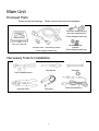
Main Unit
Enclosed Parts
This kit includes the followings. Please check all items before the installation.
Connector, Rubber-bushing
qt.3/each (3 spares/each)
(Turbo-charged models only)
REYTEC main unit
Boost pressure sensor, Coupler, Cable,
Pressure hose, T-connector qt.1/each
(Turbo-charged models only)
M6 bolts and nuts
qt.2/each
(Turbo-charged models only)
Necessary Tools for Installation
Screwdrivers
Wrenches
A set of Ratchet wrench
Connector Pliers
Timing light
4
Solder and Solder iron
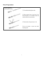
Wire Preparation
Terminal Preparation
(For Boost pressure sensor)
① Put a rubber-bushing thru a wire.
② Remove about 3mm of vinyl tunic of the
wire and place it on a terminal. Pinch the
smaller nails with connector pliers.
③ Paste solder to the part shown in ②.
④ Put the insulator in place and pinch
remaining nails.
5
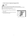
1. Removing the Originally Equipped ECU
NOTE
■ Turn the ignition switch OFF before begin installation, and disconnect a battery.
■ Do not touch terminals of the unit. A computer chip inside may be destroyed with static electricity.
■ Do not pull connectors with excessive force.
■ Make sure the wires are not pulled too tight and pinched.
① Factory equipped ECU can be found in the place shown in
illustration below.
② Loosen the bolts from ECU, and disconnect the connector. Pull
connector itself but not wire harness.
(Left side, under passenger seat)
6
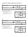
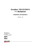
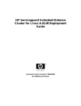
2. Aquiring A/F Signal and Fitting Air-temp Sensor
【R32】
R32 rear view of connecter
Boost output signal
Ground
Line for A/F output signal
Obtaining A/F logger output signal
① Connect A/F output line to 55th (white) wire
Ground
30(black)
(line for O2 sensor).
② Connect the ground wire to 30th (black) wire.
30
ECU
55(white)
Line for A/F output signal
Wiring Illustration
【R33】
R33 rear view of connecter
Boost output signal
Ground
Line for A/F output signal
Obtaining A/F logger output signal
② Connect A/F output line to 55th (white) wire
Ground
30(black)
(line for O2 sensor).
② Connect the ground wire to 30th (black) wire.
30
ECU
55(white)
Line for A/F output signal
Wiring Illustration
7
3. Installation of REYTEC Main Unit
NOTE
■ Do not touch the terminal of ECU. The parts inside the product may be damaged with static
electricity.
① Check the terminal for damage and bend. Fit the connector to the terminal.
② Tighten the lock screw till the colored (in orange) nail of the connector sits on the terminal.
4. Fitting Boost Pressure Sensor
NOTE
■ Bndle and organize all the wires and hoses so that they do not touch any moving part in Engine
compartment.
■ Do not fit any installment such as pressure gauges, to pipe line of the Boost pressure sensor, intake
manifold, T-connector and fuel regulator.
■ Boost pressure sensor must be fitted its pressure output part facing down.
8
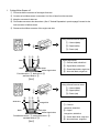
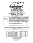
1. Cutting Airflow Sensor off
① Pull out the Airflow connector of the engine front side.
② Cut wires of an Airflow sensor. Leave about 3 to 5cm of wires from the connector.
③ Keep the connector for later use.
④ Fit a female connector to the wires above. (See 2. Terminal Preparation in previous page) Connect it to the
male connector of airflow sensor.
⑤ Disconnect the Airflow connector of the engine rear side.
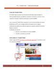
Wiring of Boost Pressure sensor
1
①-Ground (black)
2
①
③
3
④
①②
②-Signal (white)
②
③-Power (red)
③
Airflow signal wires
black
white
①-Ground(white, shield line)
②-Signal(black, shield line)
black
black-white
Airflow signal wires
Put white wire to ①, black wire to ②
③-Power(black-white, single line)
④-Not used(black, single line)
and black-white to ③.
【R32】
Wiring of Boost Pressure sensor
1
①-Ground (black)
2
①
③
3
④
①②
white-blue
②-Signal (white)
②
③-Power (red)
③
orange-blue
Airflow signal wires
①-Ground
(white-blue, shield line)
black-white
Airflow signal wires
black
Put white-blue wire to ①, orange-blue wire to ②
and black-white to ③.
②-Signal
(orange-blue, shield line)
③-Power(black-white, single line)
④-Not used(black , single line)
【R33】
9
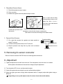
2. Fitting Boost Pressure Sensor
① Fit the Boost pressure sensor in place.
② Fit the connector.
③ Bundle and organize wires with plastic tie-wrap or similar.
There is a place ideal for fitting
the Boost pressure sensor on the
cleaner box. Drill a φ 6.0 ~
6.5mm hole, and fit it with the bolt
and nut provided.
Boost pressure sensor must
be fitted with its pressure outlet
facing down.
Example of the Boost pressure sensor location.
(Illustration is a front left side of engine compartment)
※Be careful not to break surroundings of the radiator bracket.
3. Piping for Boost Pressure
① Cut a pipe that connects fuel regulator and intake manifold to
To intake manifold
T-Connector
wedge T-connector.
② Connect enclosed pressure hose to the T-connector.
③ Keep the pressure hose away from any heat, such as exhaust
manifold.
To fuel regulator
To pressure sensor
T-Connector
5. Removing O2 sensor connector
Remove O2 sensor connector. REYTEC does not collect signal from the sensor.
6. Adjustment
① Tighten idle adjust screw on AAC valve to the end. From that position, loose the screw 3 to 4 rotation.
※If the position of throttle sensor has not been changed, skip this adjustment.
② Turn the ignition OFF for once, and then start the engine.
③ Check the engine and surroundings for any leak, spilt and other problems.
④ When the engine gets warm enough (water temperature above 70 degree), adjust initial ignition timing to
BTDC 20°.
※If rough idling occurs, try idle adjust screw ( Do not turn it more than a half rotation).
10
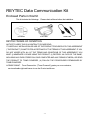
REYTEC Data Communication Kit
Enclosed Parts in this Kit
This kit includes the followings. Please check all items before the installation.
1CD-ROM
1Link Cable
1USB Cable
REYTEC TERMS OF CONDITION
NOTICE TO USER: THIS IS A CONTRACT. PLEASE READ
IT CAREFULLY. INSTALLATION OR USE OF THE PRODUCT PROVIDED WITH THIS AGREEMENT
(“THE PRODUCT”) CONSTITUTES ACCEPTANCE OF THE TERMS OF THIS AGREEMENT. IF YOU
DO NOT AGREE WITH ALL OF THE TERMS AND CONDITIONS OF THIS AGREEMENT, YOU
MUST (i) IMMEDIATELY CEASE USING THE PRODUCT, (ii) DESTROY ALL DATA OF THE SAME,
INCLUDING ANY DATA STORED ON YOUR COMPUTER AND ANY FORMS OF MEDIA, OR SEND
THE PRODUCT TO TOMEI POWERED, (iii) FOLLOW THE PROCEDURES ESTABLISHED BY
TOMEI POWERED.
LICENSE GRANT. Tomei Powered inc. ("Tomei Powered") grants you a non-exclusive,
non-transferable right and license to use the Product as follows:
11
1. COPYRIGHT. The Product is proprietary to Tomei Powered and its licensors. Tomei Powered and its licensors retain
all copyrights, trade secret rights, patents, trademarks, intellectual property rights and any other proprietary rights relating
to the Product.
2. USE of THE PRODUCT.
The Product is designed for REYTEC of Tomei POWERED ONLY. You may not use
the Product for any Electric Engine Control Unit (“ECU”) other than REYTEC, including vehicle manufacturer’s ECU.
3. LIMITATIONS.
You may not resale the Product.
You may not decompose, modify, re-engineer, re-compile, re-assemble and give any change to the Product for any
reason.
You may not lend, lease, hire and rental the Product.
You may not make any forms of copies of the Product, and you may not sell any forms of copies of the Product to the
other.
The Product may be used in Japan only.
4. LIMITATION of LIABILITY.
In no event will Tomei Powered be liable to you for any consequential, incidental or
special damages, including any loss of profits, damages, or loss of data arising out of the use or inability to use the
Product, even if Tomei Powered has been advised of the possibility of such damages. In no event shall Tomei Powered’s
liability under this agreement exceed the amount of the Product prices. The foregoing limitation shall apply not
withstanding any failure of essential purpose of any limited remedy. Some states do not allow the exclusion or limitation of
incidental, consequential or special damages, so the above limitations may not apply to you.
5. If you do not agree with all of the terms and conditions of this agreement, you must (I) immediately cease using the
Product, (ii) destroy all data of the same, including any data stored on your computer and any forms of media, or send the
Product to Tomei Powered, (iii) follow the procedures established by Tomei Powered.
12
NOTE
■ A Windows on your computer must have Japanese operating system.
■ Be careful not to scratch the CD-Rom.
■ Wipe with clean, soft cloth when the CD-ROM gets dirty.
■ Do not use solvent to clean the CD-ROM.
■ Do not put a label or sticker on the CD-ROM. Use soft felt pen when you write on the CD-ROM.
■ Do not insert a broken, deformed CD-ROM into the CD-ROM drive. Do not try to repair with glue or
cement if the CD-ROM is broken. It may ruin the drive.
■ Always store the CD-ROM in the case when done.
■ Do not pull cables when you disconnect a connector. Always grab the connector.
■ Do not leave the product under direct sunlight. Keep away from heat.
■ The content of the product is subject to change without notice.
■ In no event will Tomei Powered be liable to you for any consequential, incidental or special damages,
including any loss of profits, damages, or loss of data arising out of the use or inability to use the
product.
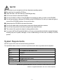
System Requirements
REYTEC requires PC to have at least the following specification.
The specification below, however, is minimum requirements and it does not guarantee the full adaptation.
OS
Windows 98 Second Edition / Me / 2000 / NT / XP
PC
AT compatible and NEC98NX series
CPU
Pentium2
Memory
128MB
HDD
100MB
Display
800 600 High Color (16 Bit)
CD-ROM Drive
Read speed 2X
A serial port RS232C type D-sub9pin male connector, or USB1.1 port is required.
Windows is a registered trademark in the U.S.A. and other countries of Microsoft Corporation.
Pentium is a registered trademark in the U.S.A. of Intel Corporation.
13
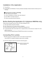
Installation of the Application
① Turn the PC on.
② Set CD-ROM into CD-ROM drive. The set up will start automatically. Follow the instruction. Reboot your PC if
necessary.
※If the set up does not start, try following:
① Select “Start” menu then “Browse”.
② Look for CD-ROM drive in “Browse” then select “setup.exe”.
③ Click “OPEN”. This will start “setup.exe”.
④ When the setup starts, follow the instruction.
Before Starting the Application (For Windows 98SE/Me only)
Please check the system resource of your PC before starting REYTEC.
① Click “My Computer” and choose “Property”.
② Click “Performance” tab. The system resource is displayed.
③ End any anti-virus soft installed on your computer before starting REYTEC.
④ To protect REYTEC Data Communication from unexpected trouble, make sure there is at least 70% of the
system resource free.
※If you have been installed Windows NT/2000/XP, this procedure is not necessary.
Connecting PC to vehicle
REYTEC uses connector of diagnosis system on the vehicle as an input terminal.
※Once REYTEC is installed, the diagnosis system will be unavailable.
The connector of diagnosis system can be found in the following place:
Right hand side of steering wheel
Above the fuse box
14
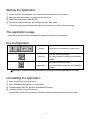
Starting the application
① A short cut of REYTEC will appear on your screen when the installation is done properly.
② Make sure all the other program, including anti-virus is shut off.
③ Double click the short cut to start REYTEC.
④ If you did not create the short cut, start the application from “Start” button.
※If you are using output device other than stated in this manual, shut it off from “Device manager”.
The application usage
Please refer to the Help screen for this application usage, each screen item, and glossary.
Key Configuration
[Arrows]
Moves cursor to the direction, so does mouse.
Increases numbers of the data.
[Page Up]
The numbers will turn red when any modification
is made.
Decreases numbers of the data.
[Page Down] The numbers will turn blue when any modification
is made.
※Data may be unable to be fluctuated unless it is pushing the Fn key depending on PC model.
Uninstalling the application
① Select “Control Panel” from “Start” menu.
② Open “ADD/REMOVE Programs” in “Control Panel”.
③ Find and highlight “REYTEC” and click “ADD/REMOVE Program”.
④ Uninstaller will starts. Follow the instruction.
※Some folders of REYTEC may remain even after uninstalling. Check these folders before you delete.
15
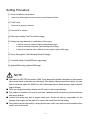
Setting Procedure
① Check fuel delivery components.
↓
Inspect fuel delivery pipe and vacuum hose for leak. Replace fuel filter.
↓
② Fit A/F meter.
↓
See previous page as a reference.
↓
③ Connect PC to vehicle.
↓
④ Start engine setting. (Real Time Monitor page)
↓
⑤ Setting may vary depends on modification of the engine.
↓
・
In case the injector is replaced. (Data Rewriting Setup3 page)
↓
・
In case the camshaft is replaced. (Data Rewriting Setup2 page)
↓
・
In case the compression ratio is different from the original. (Ignition MAP page)
↓
⑥ Set up idling speed. (Data Rewriting Setup1/2/3 page)
↓
⑦ Fuel MAP setting. (Fuel MAP/Data Logger page)
↓
⑧ Ignition MAP setting. (Ignition MAP page)
NOTE
■ Data edited on REYTEC are stored in RAM. These data will be deleted if the battery is disconnected
(the memory backs up the data only a few days). If the battery is disconnected from vehicle, you may
have to reload the data to the RAM. Even if the edited data are lost, default setting is kept so that the
engine will start.
■ When you change fuel setting, always use A/F meter to avoid engine damage.
■ This product is intended to be used at race track. Installation should be done by trained mechanics
with proper facilities.
■ Incorrect fuel setting may lead to engine break down. We do not take any responsibility for the
damage of the engine and any part of the vehicle that results from the fuel setting.
■ This product may be influenced by a strong electric wave, and it may cause incorrect operation when
used in such environment.
16
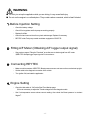
WARNING
■ Do not try to set up the application while you are driving. It may cause fatal injury.
■ Do not run the engine in a confined place. They contain carbon monoxide, which is fatal if inhaled.
1.Before Injection Setting
・
Check the battery voltage.
・
Check if fuel regulator and fuel pomp are working properly.
・
Replace fuel filter.
・
Check fuel and vacuum lines for any leak and damage. Replace if necessary.
・
REYTEC voids Fuel pump control modulator equipped on R32GT-R.
2. Fitting A/F Meter (Obtaining A/F logger output signal)
・
See previous pages “Fitting the Terminals” as a reference to obtain signal from A/F meter.
※REYTEC accepts logger input signal of 5v at maximum.
3. Connecting REYTEC
・
Make sure all connectors of REYTEC, Boost pressure sensor and vacuum lines are hooked up tight .
・
Set the cable to the diagnosis connector of the vehicle.
・
Turn ignition ON, and start the application.
4. Engine Setting
・
Check the Idle switch is “ON” at the Real Time Monitor page.
※It is not necessary to adjust the Throttle voltage for turbo charged models.
・
See if air-temperature sensor shows correct reading. Also check the Boost pressure is at about
0kg/cm2.
17
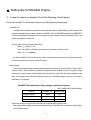
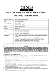
5. Setting tips for Modified Engine
① In case the injector is replaced. (Go to Data Rewriting, Setup3 page.)
Set up the Fuel MAP-Trim and Injection delay time at Data Rewriting, Setup3 page.
Fuel MAP-Trim
Fuel MAP-Trim is reflected in both Idle Fuel and Fuel MAP setting. Default setting is 100% (based on the
originally equipped injector’s capacity: 259cc for SR20DE, 370cc for SR20DET and 444cc for RB26DETT).
If injectors are replaced with larger ones, the setting has to be changed to avoid excessively rich A/F. See
following example as a reference.
E.g. OE 380cc injector is replaced with 550cc
550(cc)
380(cc) = 1.46
Then, Trim (100%) is divided by this number; in this case the number is 1.46.
100(%)
1.46 = 68.5(%)
So the Fuel MAP-Trim should be set about 68% to compensate the increase of the injector’s capacity.
The amount of the fuel is as same as the OE injector.
Injection Delay
There is a time lag that injector actually starts injecting fuel after they get order from ECU. This we call an
“Injection Delay”. When injectors are replaced, the injection delay changes as well. As a general, larger
injectors have longer injection delay. Injection Delay tends to be longer when the battery voltage is lower
than 14v and it gets shorter when the voltage is above 14v. If the battery voltage is too low, it may result in
start failure or rough idling.
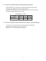
Fuel MAP-Trim and Injection Delay setting by capacity of injectors
※UJ:UNISIA JECS (Hitachi Unisia)
Injector
Fuel MAP-Trim
Injection Delay
UJ-444cc (yellow)
100%
0.82
UJ-555cc (pink)
80%
0.71
UJ-600cc (purple)
74%
0.80
※Numbers above are only yard stick and they do not guarantee the best A/F ratio.
Each injector differs slightly due to the production accuracy. Fuel MAP-Trim is reflected in both Idle Fuel
and Fuel MAP setting.
18
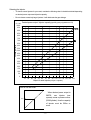
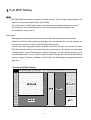
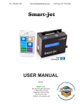
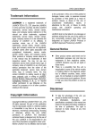
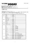
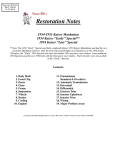
Selecting the Injector
・
To choose correct injector for your need, consider the following chart. It should be decided depending
on desired power output and injector’s capacity.
・
Do not choose excessively large injectors. It will deteriorate the gas-mileage.
(cc/min) Desired power output / Injector capacity (specific gravity of gasoline at 0.75)
1000
950
Turbo
900
850
800
750
NA
700
650
Injector Capacity
600
550
500
450
400
350
300
250
200
150
100
50
0
10
20 30
40 50 60
70 80
90 100 110 120 130 140 150
Output of each Injector (PS per 1 injector)
How to use this chart
When desired power output is
500PS,
one
injector
(one
cylinder) needs to produce 83PS
500cc
(500/6cylinder), thus the capacity
of injector must be 500cc or
more.
80ps
19
② In case the camshaft is replaced. (Data Rewriting Setup2 page)
Select Data Rewriting, then Setup2 page. Set up idling speed depending on the cam profile.
Idling speed can be adjusted by AAC valve and Ignition feed back.
Idling speed is set slightly higher at low water temperature by AAC valve for smoother operation.
Following is an example of idling speed by cam profile.
Idling Speed By Cam Profile
Camshaft
Duration
Lift
Idling Rev
TOMEI PONCAM
260°
9.15mm
900 rpm
TOMEI PROCAM
260°
10.8mm
1100 rpm
③ In case the compression ratio is different from the original. (Ignition MAP page)
If the compression ratio is higher than the stock, retard ignition timing at Ignition MAP.
Highlight the whole Ignition MAP, then press “Page down” key.
Retard about 4°to 6°when compression ratio increases 1.
20
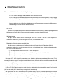
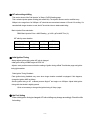
6. Idling Speed Setting
Please read the following before start setting the idling speed.
REYTEC controls air supply at idling with AAC valve and adjust screw.
Idle fuel, Idle ignition and Water-Temperature compensation at DATA Rewriting, Setup1, 2 and 3 pages
are all related to the idling control. AAC Valve Compensation, Cold start fuel compensation, A/C and P/S
compensation, too.
It may be tedious to set up idling from throttle opening and Boost pressure compared to Airflow system.
Understanding the function of AAC valve should help.
AAC Valve
AAC valve is a proportionality solenoid valve. It controls amount of the auxiliary air by the output signal that has
the frequency of about 160Hz. The amount of air increases according to the signal length.
Idle Adjust Screw
Idle adjust screw controls amount of auxiliary air and can be found at the AAC valve body. Wind it
counter-clock wise when you wish to engine rev higher, and clock wise to lower.
Relationship of Idle Adjust Screw and AAC Valve
Idle adjust screw controls amount of auxiliary air and can be found at the AAC valve body. Wind it
counter-clock wise when you wish to engine rev higher, and clock wise to lower. Following is the relationship of
AAC valve and idle adjust screw.
① Idle adjust screw is closed too much. → AAC valve opens.
② Idle adjust screw is at proper position. → AAC valve opening should be 25 to 35%.
③ Idle adjust screw is opened too far. → AAC valve closes.
In the case of ①, AAC valve will be opened too much. Actual rev will be lower than desired idling speed. Fuel is
too lean (A/F ratio too large). If idle adjust screw is tightened more, AAC valve will be opened till its end and thus will
not be able to supply air any more.
In the case of ②, the idling should be stable and smooth. AAC valve has a “slack” so that it can compensate the
change in the engine environment.
In case of ③, AAC valve is closed too much. Actual rev will be higher than desired idling speed. Fuel is too rich
(A/F ratio too small). AAC valve will keep opening/closing intermittently.
Idle adjust screw and AAC valve interfere with each other closely. Above is a general relationship of these two
items, although, it may vary depending on the modification and /or condition of an engine. Above is a general tips
rule for AAC valve and Idle adjust screw settings. It may differ by engine condition and modification made to the
engine. In such case, the adjust screw may be slightly loosen to keep AAC valve opening between 25 and 35%.
21
Idling Speed Control
By using AAC valve and getting feedback information from ignition system, idling speed is automatically
adjusted.
・
Actual idling speed is lower than desired speed.
Cause: AAC valve is opened too far already. Fuel is too lean (A/F ratio too large). Idle adjust screw is
tighten too much.
・
Actual idling speed is higher than desired speed.
Cause: AAC valve is not opened enough. Fuel is too rich (A/F ratio too small). Idle adjust screw is
loosen too much. Air is leaking in from other than IAA unit.
・
Air inhaled does not stabilize. AAC valve keeps opening/closing intermittently.
Cause: Unstable ignition timing gives unstable feedback information. Air is leaking in from other than
IAA unit.
Idling speed is too low→AAC valve opens→Increase fuel to compensate AAC opening→Idling gets
higher→AAC closes→Idling gets too low…
Correcting Ignition Feedback
In case the actual rev is lower than the desired idling speed = Advance ignition timing more than 20° for RB26.
In case the actual rev is higher than the desired idling speed = Retard ignition timing more than 20° for RB26.
When the engine gets warm and the ignition gets no feedback, idling should be stable. If the idle setting is
proper, AAC valve opening should be 25 to 35%, and a difference in the actual speed and desired speed should
be smaller.
22
① Starting Engine
Start the engine with all the electric components (A/C, head lumps and etc.).
※If the battery voltage is too low, it may “wet” plugs, disabling the engine to start.
If the engine will not start, try Cold Start Fuel Compensation at DATA Rewriting, Setup3 page.
The amount of fuel at cold start is compensated depending on water and air temperature. Injection pattern
at cold start is synchronized injection. If the plugs are wet, decrease the amount of the fuel.
If it seems that the idling is stable, engine will be checked and it will warm to the water temperature of
70℃.
② AAC valve Opening Control
After warming up the engine, adjust idle screw for the AAC valve opening to be 25 to 30%. The opening
may vary slightly depending on the engine conditions.
To higher AAC valve opening Turn Idle adjust screw clockwise.
To lower AAC valve opening
Turn Idle adjust screw counter clockwise.
※When the opening exceeds the range, consider following.
☆Opening below 25%(Air supply excessive)
☆Opening above 35%(Air supply short)
・Idle adjust screw is opened too much.
・Idle adjust screw is closed too much.
・Desired idling speed is too low.
・Desired idling speed is too high.
・Throttle valve is already open.
・Idling is too rough.
・Idling is too rough.
・A/F is too lean.
・A/F is too rich.
23
③ A/F ratio setting at Idling
This can be done at “Idle Fuel Injection” of Setup1, DATA Rewriting page.
This is a basic injection pattern at idling (idle switch ON). The injection amount can be modified every
200rpm in the range from 0 to 3000rpm. A/F should be set somewhere between 12.5 and 13.0 at idling. If a
camshaft with longer duration is used, the A/F should be richer to obtain stable idling.
Basic Injection Pulse calculation
RB26 Basic Injection Pulse = MAP Reading
0.008
Fuel MAP Trim (%)
A/F ratio by cam duration
Camshaft
Duration
Lift
A/F Ratio
TOMEI PONCAM
260°
9.15mm
12.5~13.0
TOMEI PROCAM
260°
10.8mm
12.5~13.0
④ Initial Ignition Timing
Always adjust ignition timing when A/F ratio is changed.
Initial ignition timing of RB26 engine is BTDC 20°.
Adjust a crank position sensor so that the reading of ignition timing at Real Time Monitor page and ignition
timing light matches.
False Ignition Timing Feedback
False ignition timing feedback may occur when longer duration camshaft is equipped. If this happens,
change the Ignition MAP as follows:
Set the ignition timing to 20°at Boost pressure 0kg/cm2 and engine rev 3000rpm. Adjust initial ignition
timing while the throttle is slightly opened.
※It is not necessary to change Idle ignition timing of Setup1 page.
⑤ Idle Fuel Setting
When initial ignition timing is changed, A/F ratio at idling may change accordingly. Check the Idle
fuel setting.
24
⑥ Air Conditioner Compensation
Air conditioner gives heavy electrical load to engine, and it usually drops the idling when turned on (mixture
becomes lean). This feature injects more fuel when it is in use. Specify the amount of the fuel to be
increased so that the engine keeps the same idling speed despite of A/C.
⑦ Power Steering Compensation
Power steering unit too, gives heavy load to engine, and drops the idling when steered (mixture becomes
lean). Specify the amount of the fuel to be increased so that the engine keeps the same idling speed
regardless of the steering movement.
⑧ AAC Valve Compensation
After setting the Idle fuel, Initial ignition timing and AAC valve opening, Set up the amount of fuel to be
Injected when AAC valve opens. This can be done at Setup3 of DATA Writing page.
When AAC valve opens during idling, the engine may run rough (stall or cough) as a load from electrical
equipments increases. AAC Valve Compensation prevents sudden dropping of idling speed in such case.
・
AAC Valve controls the amount of air supply when the load increases.
・
AAC Compensation means that injection of fuel when AAC valve increases the air supply.
For instance, consider followings.
At idling, water temperature at 70 degree in Celsius and A/F ratio at 12.7, AAC valve opening 30% and
idling speed at 950rpm. AAC valve opening rises to 60% as electrical load increase for some reason
(heater ON, wiper moving, head light ON and etc.), and it reduces A/F ratio. For that reason, idling speed
may drop too low or engine may stall. If compensation starts at the point of AAC valve opening 45%, 15%
advantage can be obtained, and keeps A/F in proper ratio. As a result, the idling speed gets back to the
original rev before engine stalls. Once idling backed up at the original rev, AAC valve opening backs to
original rev as well. Specify when to start this compensation in throttle opening (in percent).
Set AAC compensation to start at AAC valve opening +10 to 15%, idling stable.
Turn A/C and P/S off, head lumps and heater on to set the starting position.
⑨ Before setting Water-Temperature Compensation
An engine has to be cold when setting Water-Temperature Compensation.
※S14 and S15 has a regulator on the throttle valve, thus idle switch will be turned OFF. REYTEC refers to
Fuel MAP when engine is cold (Idle switch OFF, that is), not Idle fuel setting of Setup1 page. Idling setting at
cold start of S14 and S15 should be done at Fuel MAP.
25
⑩ Water-Temperature Compensation
In order to burn fuel more efficiently while the engine is cold at start, REYTEC increases the amount of fuel.
The amount of increase (Shown in %) is reflected on the Idle Fuel and Fuel MAP.
Desirable A/F Ratio by Water Temperature
Water Temp.
A/F at Idle
-40℃~ 0℃
Apprx 12.0
0℃~40℃
Apprx 12.5
40℃~60℃
Apprx 13.0
70℃~above
No Compensation
26
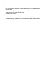
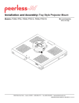
7.Fuel MAP Setting
GT-R
REYTEC-RB26Turbo controls fuel injection by Boost pressure. From the data of Boost pressure and
engine rev, you can trace where to look in the Fuel MAP.
The vertical axis of Fuel MAP shows engine rev and horizontal axis shows Boost pressure in kg/cm2.
The both grid can be changed. Make sure to re-set up the whole items after changing the grid.
Use a reliable A/F meter to set up.
Data Logger
Data logger records signals collected from sensors and ECU and stores those data into memory.
Watch for the A/F ratio while sampling for data logger. If the ratio becomes too lean, stop sampling. You
may need to increase the numbers in Fuel MAP before start sampling.
Choose 3 items from logger graph: Engine rev, Boost pressure and A/F ratio. You can trace from where
REYTEC extracts the data if you know the Boost pressure and engine rev. For instance, you have gained
a sampling data at 1.0kg/cm2 Boost pressure, 3000rpm to 8000rpm. The data shows the A/F ratio of 12.0,
and the desirable ratio is 11.0, you need to increase numbers of injection pulse of the Fuel MAP, at Boost
pressure 1.0kg/cm2, 3000rpm to 8000rpm. (Select Config, Fuel DispChange to change Bit-view/Pulse
page view.)
Example of A/F Ratio Setting
A/F 13~13.5
A/F 11~11.5
A/F 12
A/F 11.8
A/F 11
A/F 12.5
27
Fuel Increase at Acceleration
REYTEC injects extra fuel at acceleration. To inject the right amount of fuel, it sense the acceleration from
the throttle opening.
Programmed data for RB26 continuously compensates the amount of fuel.
The adjustment should be done after setting of Fuel MAP.
Desirable A/F ratio is around 13.0.
Fuel Decrease at Acceleration
This is to set back the increased fuel to a basic injection pattern. When the fuel is injected more for
acceleration, it has to be decreased more. Time needed for time compensation will be shortened by
increasing numbers in Fuel Decrease setting.
28
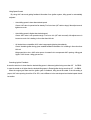
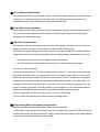
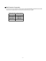
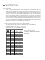
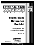
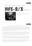
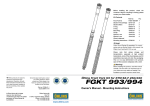
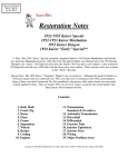
8. Ignition MAP Setting
Ignition Timing Control
In order to obtain an optimal performance, REYTEC controls ignition timing depending on the driving
condition. As long as the compression ratio is kept original, resetting is unnecessary. A knock sensor is not
used for REYTEC, as the sensor originally equipped by manufacturer is usually a radio-wave sensing type,
and it tends to pick up the noise created by engine modification. When you want to change ignition timing,
you should use microphone, amplifier and headphone to check the engine knocking. Place microphone
near the engine block, and listen for the knocking noise while you advance/retard ignition timing. Check the
spark plugs as well. Do not advance ignition timing too much, as it will break engine at higher load. Even if
you do not sense engine knock, advancing ignition timing excessively cause improper combustion. Ignition
timing can be adjusted in the range of 0 to 50 degrees in the Ignition MAP.
・ In case the compression ratio differs from the original (Ignition MAP page)
If the compression ratio is higher than the stock, retard ignition timing at Ignition MAP page.
Highlight the whole Ignition MAP, then press “Page down” key.
Retard about 4°to 8°when compression ratio increases 1.
Turbo
Engine
Rev
1.1kg/cm
1.3kg/cm
1.5kg/cm
800
15
15
15
1200
16
16
16
1600
17
17
17
2000
18
18
18
2500
19
19
19
3000
24
20
20
3500
25
23
22
4000
25
24
23
4500
26
23
22
5000
26
23
22
5500
25
23
22
6000
24
24
21
6500
25
24
21
7000
25
23
21
7500
25
24
22
8000
26
25
23
Boost
Boost
2
Boost
2
Camshaft::TOMEI PONCAM
2
Turbo Charger:ARMS-B7660 or equivalent
Output:600ps
29
Saving the Edited File
Select “File Control” from Menu page. Clicks “save” to save the data. You can choose where to save it.
Default setting is a “Data” folder. Click “load” to load the data you have saved.
File name is pre-set, such like “data name. extension (varies by vehicle and PC)”.
GT-R R32highpressure *.hrt
standard*.lrt
R33highpressure *.hrc
standard*.lrc
(*: File name)
REYTEC cannot handle different types of extension other than above. You will have to change the
extensions when the different types of them are used.
30
31
Sales Department TEL+81 42 795 8411
●Please call the number above for inquiry.
Business Hours: Monday thru Friday (Closed on National Holidays) 9:00-18:00
1737-3 Tsuruma, Machida,
Tokyo 194-0004
JAPAN
TEL +81 42 795 8411
FAX +81 42 799 7851
URL http://www.tomei-p.co.jp
REYTEC for GT-R 03.8 E81040
32