1
SIMATIC
PCS 7 process control system
Service support and diagnostics
(V8.0)
Preface
1
Additional support
2
Ensuring Availability
3
Configuring diagnostics
conditions
4
Message concept of PCS 7
5
Failure - What next?
6
Diagnostics in PCS 7
7
Failure, replacement and
return
8
Service Manual
03/2012
A5E02779775-02
Legal information
Warning notice system
This manual contains notices you have to observe in order to ensure your personal safety, as well as to prevent
damage to property. The notices referring to your personal safety are highlighted in the manual by a safety alert
symbol, notices referring only to property damage have no safety alert symbol. These notices shown below are
graded according to the degree of danger.
DANGER
indicates that death or severe personal injury will result if proper precautions are not taken.
WARNING
indicates that death or severe personal injury may result if proper precautions are not taken.
CAUTION
with a safety alert symbol, indicates that minor personal injury can result if proper precautions are not taken.
CAUTION
without a safety alert symbol, indicates that property damage can result if proper precautions are not taken.
NOTICE
indicates that an unintended result or situation can occur if the relevant information is not taken into account.
If more than one degree of danger is present, the warning notice representing the highest degree of danger will be
used. A notice warning of injury to persons with a safety alert symbol may also include a warning relating to property
damage.
Qualified Personnel
The product/system described in this documentation may be operated only by personnel qualified for the specific
task in accordance with the relevant documentation, in particular its warning notices and safety instructions. Qualified
personnel are those who, based on their training and experience, are capable of identifying risks and avoiding
potential hazards when working with these products/systems.
Proper use of Siemens products
Note the following:
WARNING
Siemens products may only be used for the applications described in the catalog and in the relevant technical
documentation. If products and components from other manufacturers are used, these must be recommended or
approved by Siemens. Proper transport, storage, installation, assembly, commissioning, operation and
maintenance are required to ensure that the products operate safely and without any problems. The permissible
ambient conditions must be complied with. The information in the relevant documentation must be observed.
Trademarks
All names identified by ® are registered trademarks of Siemens AG. The remaining trademarks in this publication
may be trademarks whose use by third parties for their own purposes could violate the rights of the owner.
Disclaimer of Liability
We have reviewed the contents of this publication to ensure consistency with the hardware and software described.
Since variance cannot be precluded entirely, we cannot guarantee full consistency. However, the information in
this publication is reviewed regularly and any necessary corrections are included in subsequent editions.
Siemens AG
Industry Sector
Postfach 48 48
90026 NÜRNBERG
GERMANY
A5E02779775-02
Ⓟ 05/2012 Technical data subject to change
Copyright © Siemens AG 2012.
All rights reserved
Table of contents
1
Preface.........................................................................................................................................................7
2
Additional support.......................................................................................................................................11
3
Ensuring Availability....................................................................................................................................13
3.1
Introduction..................................................................................................................................13
3.2
3.2.1
3.2.2
3.2.2.1
3.2.2.2
3.2.2.3
3.2.2.4
3.2.2.5
3.2.2.6
3.2.2.7
3.2.3
3.2.3.1
3.2.4
3.2.4.1
3.2.4.2
3.2.4.3
3.2.4.4
3.2.5
3.2.5.1
3.2.5.2
3.2.5.3
3.2.6
3.2.6.1
3.2.7
3.2.7.1
Data backup................................................................................................................................14
Options for data backup..............................................................................................................14
Backing up ES project data.........................................................................................................16
How to back up parameter settings of the SIMATIC station........................................................16
How to archive a project..............................................................................................................17
How to retrieve a project..............................................................................................................19
How to archive and retrieve a multiproject..................................................................................20
How to archive custom libraries...................................................................................................21
How to export operator and display texts....................................................................................22
How to back up custom functions and actions............................................................................23
Backing up OS project data.........................................................................................................24
Backing up configuration data.....................................................................................................24
Backing up batch data.................................................................................................................25
Backing up configuration data.....................................................................................................25
How to generate a backup...........................................................................................................25
How to restore data from a backup.............................................................................................27
How to archive batches...............................................................................................................28
Backing up SIMATIC Route Control data....................................................................................29
Backing up configuration data.....................................................................................................29
How to back up project data from SIMATIC Route Control ........................................................29
How to restore data from a backup.............................................................................................30
Creating an image.......................................................................................................................31
Backing up data by generating an image file...............................................................................31
Comparing project versions.........................................................................................................32
Comparing project versions with VXC.........................................................................................32
3.3
3.3.1
3.3.2
3.3.3
3.3.3.1
3.3.3.2
3.3.4
3.3.4.1
3.3.4.2
3.3.5
3.3.5.1
3.3.5.2
3.3.5.3
3.3.5.4
3.3.6
Hardware update.........................................................................................................................32
Hardware updates.......................................................................................................................32
How to make adjustments after a hardware change...................................................................35
Updating the CPU........................................................................................................................35
How to perform a firmware update for the CPU (as of V5.0).......................................................36
How to perform a firmware update for the H-CPU (as of V4.5)...................................................38
Updating an interface module......................................................................................................39
Updating an interface module (IM)..............................................................................................39
How to perform a firmware update of an interface module (IM)..................................................40
Updating a CP xxx.......................................................................................................................41
Updating a communication processor (CP).................................................................................41
How to perform a firmware update of the CP 341.......................................................................42
How to perform a firmware update of the CP 443-1....................................................................43
How to perform a firmware update of the CP 443-5 Extended....................................................45
Working with GSD files................................................................................................................48
Service support and diagnostics (V8.0)
Service Manual, 03/2012, A5E02779775-02
3
Table of contents
4
3.3.6.1
Working with GSD files................................................................................................................48
3.4
3.4.1
Software update..........................................................................................................................49
Software updates.........................................................................................................................49
3.5
Updating the PCS 7 OS in runtime..............................................................................................50
Configuring diagnostics conditions.............................................................................................................51
4.1
5
6
7
4
Requirements for diagnostics......................................................................................................51
Message concept of PCS 7........................................................................................................................53
5.1
Servicing a system - message concept.......................................................................................53
5.2
PCS 7 message system..............................................................................................................54
5.3
Origin of a message....................................................................................................................55
5.4
How to determine the source of a message................................................................................56
5.5
5.5.1
5.5.2
5.5.3
5.5.4
5.5.5
5.5.6
5.5.7
Understanding messages............................................................................................................57
Introduction..................................................................................................................................57
Message types in message lists and archives............................................................................58
Target groups of messages.........................................................................................................58
Message lists in process mode...................................................................................................59
Overflow of message buffer.........................................................................................................60
Message priorities.......................................................................................................................61
Influencing messages..................................................................................................................62
Failure - What next?...................................................................................................................................63
6.1
Activities in the event of a fault....................................................................................................63
6.2
6.2.1
6.2.2
6.2.3
6.2.4
6.2.5
6.2.6
6.2.7
Preparing for expert support........................................................................................................64
Information on cause of fault.......................................................................................................64
Plant documentation....................................................................................................................65
How to read the CPU diagnostic buffer.......................................................................................66
CPU fault - preparing diagnostics................................................................................................66
How to back up the diagnostic data of the PCS 7 OS.................................................................68
Remote diagnostics of a PCS 7 system......................................................................................69
Interactive operator control and monitoring with the OS Web Option.........................................70
Diagnostics in PCS 7..................................................................................................................................73
7.1
Diagnostic capabilities in PCS 7 subsystems..............................................................................73
7.2
Diagnostics with the maintenance station (asset management).................................................75
7.3
Diagnostics for PC user settings.................................................................................................77
7.4
Diagnostics for PC components..................................................................................................77
7.5
Diagnostics for network connections...........................................................................................79
7.6
Diagnostics during configuration.................................................................................................80
7.7
Diagnostics for the CPU..............................................................................................................81
7.8
Diagnostics for modules..............................................................................................................81
7.9
Diagnostics for PROFIBUS DP...................................................................................................82
7.10
Diagnostics on PROFINET..........................................................................................................82
Service support and diagnostics (V8.0)
Service Manual, 03/2012, A5E02779775-02
Table of contents
7.11
Diagnostics for PROFIBUS PA....................................................................................................83
7.12
Diagnostics on FOUNDATION Fieldbus......................................................................................84
7.13
Diagnostics for the OS.................................................................................................................84
7.14
Diagnostics for the BATCH Stations............................................................................................85
7.15
Diagnostics for the Route Control stations..................................................................................86
7.16
Diagnostics for time of day..........................................................................................................86
7.17
Diagnostics for hardware displays...............................................................................................87
7.18
Diagnostic tools...........................................................................................................................90
7.18.1 Diagnostics tools of PCS 7..........................................................................................................90
7.18.2 Diagnostics for the PCs...............................................................................................................91
7.18.2.1 Windows System Information......................................................................................................91
7.18.2.2 Managing the operating system..................................................................................................91
7.18.2.3 Shares for drives, folders and files..............................................................................................92
7.18.2.4 System tools - Local Users and Groups......................................................................................93
7.18.2.5 Command line commands...........................................................................................................93
7.18.2.6 Set PC station..............................................................................................................................94
7.18.2.7 Set PG/PC interface....................................................................................................................94
7.18.2.8 Station Configuration Editor.........................................................................................................95
7.18.2.9 Printers and print jobs..................................................................................................................96
7.18.2.10 PC DiagMonitor......................................................................................................................97
7.18.2.11 Installed SIMATIC software....................................................................................................97
7.18.3 Diagnostics in the network...........................................................................................................97
7.18.3.1 NetPro.........................................................................................................................................97
7.18.3.2 NCM S7 Industrial Ethernet.........................................................................................................98
7.18.3.3 SIMATIC NET switches - SCALANCE X-300 / X-400.................................................................99
7.18.3.4 "Network Connections" Windows dialog box...............................................................................99
7.18.3.5 NCM S7.......................................................................................................................................99
7.18.3.6 Topology Editor (PROFINET)....................................................................................................100
7.18.3.7 MBSA........................................................................................................................................101
7.18.4 Operator station diagnostics......................................................................................................101
7.18.4.1 Lifebeat monitoring....................................................................................................................101
7.18.4.2 Simatic Shell..............................................................................................................................101
7.18.4.3 WinCC "System Info" channel...................................................................................................102
7.18.4.4 User Administrator.....................................................................................................................103
7.18.4.5 WinCC Channel Diagnostics.....................................................................................................104
7.18.4.6 Status of multi-user operation....................................................................................................104
7.18.4.7 Status of connections................................................................................................................105
7.18.4.8 Area overview............................................................................................................................105
7.18.4.9 Redundancy status display........................................................................................................106
7.18.4.10 Time master role of the OS server (status)..........................................................................106
7.18.5 Diagnostics for the BATCH station............................................................................................107
7.18.5.1 Status icons in the BATCH server taskbar................................................................................107
7.18.6 Diagnostics for the Route Control station..................................................................................109
7.18.6.1 Status icons in the Route Control server taskbar......................................................................109
7.18.7 Diagnostics for the SIMATIC station..........................................................................................109
7.18.7.1 SIMATIC Manager.....................................................................................................................109
7.18.7.2 HW Config.................................................................................................................................111
7.18.7.3 Module information....................................................................................................................112
Service support and diagnostics (V8.0)
Service Manual, 03/2012, A5E02779775-02
5
Table of contents
7.18.7.4
7.18.7.5
7.18.8
7.18.8.1
7.18.8.2
7.18.8.3
7.18.8.4
7.18.8.5
8
PROFIBUS diagnostics with diagnostic repeater......................................................................113
SIMATIC PDM...........................................................................................................................114
Additional diagnostic options.....................................................................................................115
Additional diagnostic options for PCS 7....................................................................................115
Amprolyzer (add-on product).....................................................................................................116
BANY (add-on product).............................................................................................................117
BT 200 bus test device..............................................................................................................119
SYSTEM Process Control Diagnostics (add-on product)..........................................................119
Failure, replacement and return................................................................................................................121
8.1
Failure, replacement and return - guide to documentation........................................................121
Index.........................................................................................................................................................125
6
Service support and diagnostics (V8.0)
Service Manual, 03/2012, A5E02779775-02
1
Preface
Purpose of this documentation
This documentation contains information to support you in the following:
● Performing steps to ensure the availability of a PCS 7 system
● Verifying requirements for effective diagnostics for your PCS 7 system
● Understanding the alarm concept of a PCS 7 system
● Responding appropriately to faults and preparing detailed information about the state of
the PCS 7 system for service experts
● Selecting the correct diagnostic tool, enabling you to perform diagnostics on your PCS 7
system with the help provided
Disclaimer of liability
WARNING
Siemens assumes no liability for inappropriate use of the instructions provided in this
documentation or any consequences that might result for the customer.
● Only trained service employees should be authorized to work on the process control
system.
● Always observe the plant-specific rules and government regulations when making
changes to your system.
● Observe the plant-specific boundary conditions and adjust the work accordingly.
● Always bear in mind that changes in a system can impact other sections of the system.
Target Audience of this Documentation
This documentation is intended for use by the following trained service personnel (Service
Level 1):
● PCS 7 users
● SIMATIC S7 specialists
Service support and diagnostics (V8.0)
Service Manual, 03/2012, A5E02779775-02
7
Preface
Options for accessing PCS 7 documentation
Note
PCS 7 Readme
The information given in the PCS 7 Readme on the Internet takes precedence over all the
PCS 7 manuals. Please read this PCS 7 Readme carefully; it contains important information
and amendments on PCS 7 for you.
● The PCS 7 Readme on the Process Control System; SIMATIC PCS 7 DVD includes
important notes on PCS 7 and takes precedence over the documentation supplied for
PCS 7.
● Following the installation of PCS 7, you can find documents such as Process Control
System PCS 7; PCS 7 Readme and What's New in PCS 7? via the submenu SIMATIC >
Product Information > <Language>.
As of PCS 7 V8.0, you obtain basic PCS 7 system documentation with the Process Control
System; SIMATIC PCS 7 DVD.
The PCS 7 Internet site www.siemens.com/pcs7-documentation (www.siemens.com/pcs7documentation) provides convenient access to the complete PCS 7 documentation. You can
find the following for current PCS 7 versions:
● In the section "Hardware manuals for SIMATIC PCS 7 ..."
– The manuals for components approved for a PCS 7 version
● In the section "Software manuals for SIMATIC PCS 7 ..."
– The complete system documentation
The separate setup program for PCS 7 documentation and the PCS 7 help system for
download. After the installation of the setup program, you will find the documentation at
the following locations on the Engineering Station:
- as online help (CHM file) for the SIMATIC Manager application
- as PDF file in the Windows Start menu with the SIMATIC documentation
– The complete documentation for PCS 7 as a Manual Collection
Validity of the documentation
This documentation is valid for the Process Control System; SIMATIC PCS 7 software
package, V8.0 or higher.
Required Knowledge
This documentation provides information about working with PCS 7 and is intended for trained
service personnel. The following knowledge is required to understand the documentation:
● Basic knowledge of Microsoft Windows operating systems
● Knowledge of the functions and configurations of SIMATIC PCS 7 (Engineering System,
PCS 7 Operator Station).
8
Service support and diagnostics (V8.0)
Service Manual, 03/2012, A5E02779775-02
Preface
● Knowledge of the functions and configurations of SIMATIC S7 (S7-400, STEP 7)
● Knowledge of the functions and configurations of SIMATIC NET (network components and
transmission media)
Important information about this documentation
This documentation is a guide for service support. It therefore does not claim to be complete.
Due to our lack of knowledge of the particular circumstances in your plant, we cannot
guarantee the following with this documentation:
● That you will be able to use this documentation to remedy problems yourself.
● That, if service is required (similar to what is presented), the procedure described will
necessarily enable you to find the cause of the fault or to correct the fault.
● That detailed information about individual hardware or software components is complete.
● That detailed information about individual hardware or software errors is complete.
● That this documentation cannot provide the same expert knowledge as that provided by a
service technician or a member of the hotline staff.
● That procedures carried out will not disturb the system.
● That the procedures described can be performed via remote access.
Changes Compared with the Previous Version
Below you will find an overview of the most important changes in the documentation compared
to the previous version:
New as of PCS 7 V8.0 Update 1
● Diagnostic tools for PROFINET
● Diagnostic tools for FOUNDATION Fieldbus
● BANY for PROFINET
New as of PCS 7 V8.0
● Monitoring the time synchronization of the OS server
For additional information, refer to the section "Time master role of the OS server (status)
(Page 106)."
● Diagnostic tools for the following operating systems:
– Microsoft Windows 7
– Windows Server 2008
New since PCS 7 V7.0
● Maintenance station for universal diagnostics/maintenance in PCS 7
You can find information about this in the section "Diagnostics with the maintenance station
(asset management) (Page 75)".
● Diagnostics for PROFIBUS PA
You can find information on this in the section" Diagnostics for PROFIBUS PA (Page 83) ".
Service support and diagnostics (V8.0)
Service Manual, 03/2012, A5E02779775-02
9
Preface
● Diagnostic tools for the following operating systems:
– Microsoft Windows XP Professional
– Windows Server 2003
● Other diagnostic tools:
– Simatic Shell (Page 101)
– Microsoft Baseline Security Analyzer (MBSA) (Page 101)
– BANY PROFIBUS (Page 117)
Conventions
In this documentation, the names of elements in the software interface are specified in the
language of this documentation. If you have installed a multi-language package for the
operating system, some of the designations will be displayed in the base language of the
operating system after a language switch and will, therefore, differ from the designations used
in the documentation.
10
Service support and diagnostics (V8.0)
Service Manual, 03/2012, A5E02779775-02
Additional support
2
If this manual does not contain the answers to any questions you may have about how to use
the products described, please contact your local Siemens representative.
You can locate your local representative at:
http://www.siemens.com/automation/partner (http://www.siemens.com/automation/partner)
The guide that provides details of the technical documentation offered for the individual
SIMATIC products and systems is available at:
http://www.siemens.com/simatic-tech-doku-portal (http://www.siemens.com/simatic-techdoku-portal)
The online catalog and online ordering system are available at:
http://mall.automation.siemens.com/ (http://mall.automation.siemens.com/)
Technical support
Technical support for all A&D products can be accessed
● Via the Support Request web form
Technical support (http://www.siemens.en/simatic-tech-doku-portal)
● You can find additional technical support information in the Internet at
http://www.siemens.com/automation/service (http://www.siemens.de/automation/supportrequest)
Service & Support on the Internet
In addition to our documentation pool, we also offer you a knowledge base on the Internet.
http://www.siemens.com/automation/service&support (http://www.siemens.com/automation/
partner)
Here you will be able to access:
● The newsletter, which will keep you constantly up-to-date with the latest information about
our products
● The right documents via our Service & Support search facility
● A forum that provides users and specialists with an international platform for exchanging
experiences
● Your local Automation & Drives representative
● Information about local service, repairs, spare parts The "Our service offer" section offers
even more options.
Service support and diagnostics (V8.0)
Service Manual, 03/2012, A5E02779775-02
11
Ensuring Availability
3.1
3
Introduction
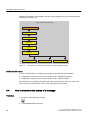
Overview
This section presents measures for ensuring availability of a PCS 7 system.
You can find information on fault-tolerant systems in the Process Control System PCS 7; FaultTolerant Process Control Systems manual.
The information in this section enables you to perform the following tasks:
● Maintain the specified condition of a system.
Examples: Adherence to maintenance intervals, replacement of batteries
● Optimize the system and prevent faults
Examples: perform firmware updates, eliminate known sources of errors
● Minimize downtime caused by faults
Examples: provide backups
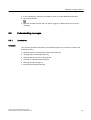
Note to reader
This section is split up into several topical fields. The following information is provided for each
topic area:
What?
What is described?
When?
When can you perform this action?
How ?
You can find Information on the topic in the section entitled "...".
Service support and diagnostics (V8.0)
Service Manual, 03/2012, A5E02779775-02
13
Ensuring Availability
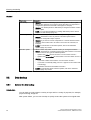
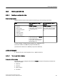
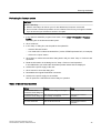
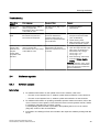
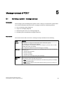
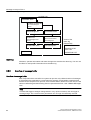
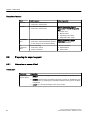
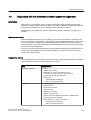
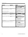
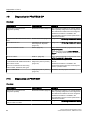
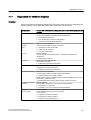
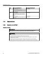
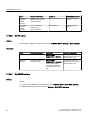
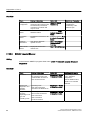
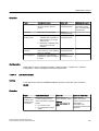
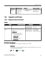
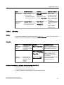
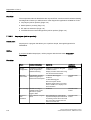
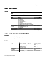
3.2 Data backup
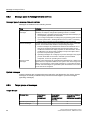
Content
Topic area
Information
Data backup
● WHAT?: Information on backing up and restoring data in a PCS 7 plant.
Backups are necessary if you want to restore the state of a component or
configuration (because a hard disk is damaged, for example).
● WHEN?: You should perform a data backup if changes have been made in
a PCS 7 plant.
● HOW?: You can find information on creating data backups in the section
"Options for data backup (Page 14)".
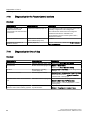
Hardware update
A SIMATIC station may switch to STOP mode if you change the hardware.
● WHAT?: Information on how to perform a firmware update and the
subsequent configuration steps required.
● WHEN?: If you want to convert components to a current firmware version
(because new functions are to be used or errors must be corrected, for
example).
● HOW?: For information on firmware updates, refer to the "hardware
updates (Page 32)" section.
Software update
A SIMATIC station may switch to STOP mode if you change the software.
● WHAT?: Information on converting projects from older versions to a current
version. There are two types of software updates:
–
Updates that utilize the new functions of a new version of PCS 7
–
Updates that do not utilize the new functions of a new version of PCS 7
● WHEN?:
–
If you want to utilize new functions of a new version of PCS 7.
–
If you want to continually adapt your PCS 7 projects to the current state
of technology.
–
If software corrections necessitate conversion.
● HOW?: For information about software updates, refer to the "Software
updates (Page 49)" section.
3.2
Data backup
3.2.1
Options for data backup
Introduction
You can back up project data in a variety of ways and for a variety of purposes, for example,
project archiving, image file.
After system failure, you can use a backup to quickly restore the system to its original state.
14
Service support and diagnostics (V8.0)
Service Manual, 03/2012, A5E02779775-02
Ensuring Availability
3.2 Data backup
Recommendations for increasing data security
● Always back up the data in the following cases:
– After configuration changes
– Before and after system component upgrades
– Before and after configuration software upgrades
● Keep at least the three most recent versions of your PCS 7 project.
● Use different storage media for backing up the data.
Examples:
– LAN hard disk
– USB hard disk
– MOD
– CD/DVD
This retains availability of your data even after failure of a device.
● You can also backup your data on hard disks of PCs in a network. Simultaneous hard disk
failures on more than one PC are very unlikely.
Data backup options
The sections below describe the options for backing up data:
Backing up ES project data
● Backing up parameter settings of the SIMATIC station (Page 16)
● Archiving a PCS 7 project (Page 17)
● Retrieving a PCS 7 project (Page 19)
● Archiving and retrieving a multiproject (Page 20)
● Archiving custom libraries (Page 21)
● Exporting operator and display texts (Page 22)
● Backing up custom functions and actions (Page 23)
Backing up OS project data
● Backing up OS configuration data (Page 24)
Backing up batch data
● Backing up configuration data (Page 25)
● Generating a backup (Page 25)
● Restoring data from a backup (Page 27)
● Archiving batches (Page 28)
Backing up SIMATIC Route Control data
Service support and diagnostics (V8.0)
Service Manual, 03/2012, A5E02779775-02
15
Ensuring Availability
3.2 Data backup
● Backing up configuration data (Page 29)
● Backing up project data from SIMATIC Route Control (Page 29)
● Restoring data from a backup (Page 30)
Creating an image file
● Backing up data by generating an image file (Page 31)
Note
Make sure that backups are stored in a protected location (in separate rooms, fireproof
cabinets, etc.).
Make sure the backups are readable (particularly when reusable storage media such as
floppy disks are used).
3.2.2
Backing up ES project data
3.2.2.1
How to back up parameter settings of the SIMATIC station
Introduction
You can change parameters (such as controller settings) online in the SIMATIC station using
the PCS 7 OS and the engineering station.
Some situations make it necessary to back up the current data blocks, FBs or parameter
settings from the SIMATIC station. This is the case, for example, when the configuration data
have been restored from a data backup.
You can make use of the following backup options:
● Reading data blocks and FBs from the SIMATIC station
● Reading charts with current parameters from the SIMATIC station
NOTICE
These actions overwrite all settings in the configuration with the current values of the
system. Make sure that the settings for start values, for example, are correctly maintained.
DANGER
If you read back the data from the SIMATIC Station, you must ensure that hazardous
conditions cannot occur following a hot restart of the system or after configuration data
are downloaded.
16
Service support and diagnostics (V8.0)
Service Manual, 03/2012, A5E02779775-02
Ensuring Availability
3.2 Data backup
Reading data blocks and FBs from the SIMATIC station
1. Open the project in the SIMATIC Manager.
2. Select the menu command View > Online.
3. In the tree view, select the data blocks and FBs you want to read from the SIMATIC Station.
4. Select Edit > Copy from the menu.
5. Select the menu command View > Offline.
6. Select Edit > Paste from the menu.
Reading charts with current parameters from the SIMATIC station
1. Double-click any CFC chart in SIMATIC Manager to start the CFC Editor.
2. Select the menu command Chart > Read Back.
3. In the "Read Back Chart" dialog box, make the following settings:
– Source files: Program of the CPU
– Scope: OCM-capable parameters
Recommendation: back up the project at this point. You can find information on this in the
section "How to archive a project (Page 17)".
This data backup includes all current parameter settings of the SIMATIC station.
3.2.2.2
How to archive a project
Introduction
You can use various tools to archive project data.
Below, the PKZip (PKZip Server) program is used for archiving:
You can find the setup for PKZip on the SIMATIC PCS 7-DVD. PKZip is automatically installed
during the PCS 7 system setup.
You can start PKZip from the SIMATIC Manager.
Requirement
● A tool is installed for archiving project data (default: PKZip).
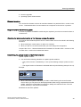
Making settings in SIMATIC Manager
1. In SIMATIC Manager, select the menu command Options > Settings.
The "Settings" dialog box opens.
2. Select the "Archive" tab.
3. Select your "preferred archiving program" from the drop-down list box (PKZip is the default).
Service support and diagnostics (V8.0)
Service Manual, 03/2012, A5E02779775-02
17
Ensuring Availability
3.2 Data backup
4. Select the following "options":
– Check options
– Check target directory on retrieval
5. You can set the default path for the archiving or retrieving projects in the "Archive directory
during" area.
6. Click "OK" to apply your settings.
Archiving a project
1. In SIMATIC Manager, select the menu command File > Archive
The "Archive" dialog box opens.
2. Select the "Multiprojects" (or "User Projects") tab.
3. Click "Browse" and select the project you want to archive from the list.
4. Click "OK" to save your settings.
The "Archive - Select Archive" dialog box opens.
5. Make the following settings for the archiving:
– Select the drive and folder for the archive file from the "Save" drop-down list.
– In the "File name" box, enter the file name under which the archive file should be saved.
Recommendation:
Name the archive file of the project in such a way that it allows you to deduce the date
of the archiving from the name. Example: "yearmonthdayprojectname"; 091230name
6. Click "Save" to apply your settings.
The "Archive – Options" dialog box opens.
7. If you want to archive the project on floppy disks, select the size of the diskette.
For additional information about this dialog box, click "Help".
8. Click "OK".
The archiving process begins.
When the "Archive" dialog box closes, archiving is completed.
Write protection
Note
If you copy the project directly to the CD/DVD, all files and directories will be write-protected.
Before using the project again, you need to remove the "Read-only" file attribute for all files
and folders in the project.
Backing up configuration data
Also back up the following configuration data:
● GSD files (Siemens\STEP 7\S7Data\GSD) to another partition or to another drive
● C scripts of the standard functions
18
Service support and diagnostics (V8.0)
Service Manual, 03/2012, A5E02779775-02
Ensuring Availability
3.2 Data backup
Backup of PDM configuration data on the Engineering Station
PDM configuration data is included automatically in the backup of your PCS 7 project.
Additional information
You can find information on the product version in the PCS 7 Readme on the SIMATIC PCS
7-DVD.
3.2.2.3
How to retrieve a project
Requirements
● The tool that was used to archive the project is installed (default: PKZip).
● You set up all defaults required for the tool that is used to archive the project (for additional
information, refer to the "How to archive a project (Page 17)" section.
Note
You can find the setup for PKZip on the Process Control System; SIMATC PCS 7 DVD.
PKZip is automatically installed during the PCS 7 system setup.
Procedure
1. In SIMATIC Manager, select the menu command File > Retrieve.
The "Retrieve - Select Archive" dialog box opens.
2. Edit the following settings for the archive file:
– In the "Search in" list:
Enter the drive and folder where the project was archived.
– In the "File name" box:
Enter the name of the file where the project is archived.
3. Click "Open" to save your settings.
The "Select Destination Directory" dialog box opens.
4. Select the destination directory/project directory in the selection list.
5. Click "OK" to apply your settings.
The retrieval is finished when the "Retrieving" dialog box closes.
Service support and diagnostics (V8.0)
Service Manual, 03/2012, A5E02779775-02
19
Ensuring Availability
3.2 Data backup
3.2.2.4
How to archive and retrieve a multiproject
Introduction
You can store a multiproject in compressed form in an archive file in the same way as individual
projects or libraries. This can be done on a hard disk or on transportable storage media (such
as a ZIP disk).
If individual projects of a multiproject are stored on more than one PC in a network, you must
use the following programs to archive the multiproject:
PKZip
This program is installed automatically together with PCS 7 (STEP 7 add-on package).
Recommendation:
Archive the multiproject on an engineering server.
Requirements for archiving a multiproject
● A tool is installed for archiving project data (default: PKZip). PKZip is automatically installed
during the system setup from PCS 7.
● Archiving a multiproject is a cross-project function. Therefore, no other process can access
any of the projects in the multiproject during archiving.
Archiving a multiproject
1. Select the multiproject in SIMATIC Manager.
2. Select the menu command File > Archive.
The "Archive" dialog box opens.
3. Select the "Multiprojects" tab.
4. Confirm the selected multiproject by clicking "OK" to save your entries.
5. Make the following settings for the archiving:
– In the "Save to" drop-down list:
Select the drive and folder.
– In the "File name" box:
Enter the name of the file in which the data are to be saved.
6. Click "Save" to apply your settings.
The "Archive – Options" dialog box opens.
7. If you want to archive the project on floppy disks, select the size of the diskette.
For additional information about this dialog box, click "Help".
8. Click "OK".
The archiving process begins.
When the "Archive" dialog box closes, archiving is finished.
20
Service support and diagnostics (V8.0)
Service Manual, 03/2012, A5E02779775-02
Ensuring Availability
3.2 Data backup
Retrieving a multiproject
1. In SIMATIC Manager, select the menu command File > Retrieve.
2. In the next dialog box, select the archived multiproject.
3. Click "Open" to save your entries.
The "Select Destination Directory" dialog box opens.
4. Select the destination directory where the archive is to be unzipped. Click "OK".
The multiproject is retrieved.
After the retrieval operation, the "Retrieve" dialog box opens.
5. Click "OK".
The following is displayed in the "Retrieve" dialog box.
– The name of the retrieved project
– A prompt for opening the project
6. Click "Yes" as required to open the project, or click "No" to close the session.
Result
A subdirectory is automatically created in the destination directory you selected. The
subdirectory contains the following:
● By default: The name of the multiproject
● Individually: A unique directory name derived from the name of the multiproject
The following are placed in the subdirectory:
● Multiproject
● Projects contained in the multiproject
● Libraries, including the master data library
Once a multiproject is retrieved, all project directories of the multiproject are located on the
same level below this directory.
3.2.2.5
How to archive custom libraries
Introduction
If you have created a custom project library in PCS 7, we recommend that you archive it.
Perform the steps below for each library to be backed up.
Procedure
1. In SIMATIC Manager, select the menu command File > Archive.
The "Archive" dialog box opens.
2. Open the "Libraries" tab.
3. Click "Browse" and select the library you want to archive from the list.
Service support and diagnostics (V8.0)
Service Manual, 03/2012, A5E02779775-02
21
Ensuring Availability
3.2 Data backup
4. Click "OK" to save your settings.
The "Archive - Select Archive" dialog box opens.
5. Make the following settings for the archiving:
– In the "Save to" drop-down list:
Select the drive and folder
– In the "File name" box:
Enter the name of the file in which the data are to be saved.
6. Click "Save" to apply your settings.
The archiving process begins.
3.2.2.6
How to export operator and display texts
Introduction
To visualize the process on the operator station you use faceplates, which show the plant
operator the measured values, operating limits, units, and operator texts of the blocks, for
example.
If you have changed operator or display texts in your blocks, we recommend that you back up
the operator and display texts.
Exporting operator and display texts
In SIMATIC Manager you can export information relating to parameters, signals and messages
to a file (format: *.csv).
You can edit this file in standard MS Office applications (such as Excel and Access).
The same mechanisms that are used for converting to project-specific languages are used for
the export.
Requirement
PCS 7 allows you to store all operator and display texts in every desired language. The only
requirement is that the language is installed in your project:
● The languages available in SIMATIC Manager can be displayed via the menu command
Options > Language for Display Devices.
● The number of languages offered is specified when Windows is installed (system
characteristics).
Procedure
1. Open the project in the SIMATIC Manager.
2. In the component view, select the master data library (or, if not available, the project folder).
3. Select the menu command Options > Manage Multilanguage Texts > Export.
The "Export User Texts" dialog box opens.
22
Service support and diagnostics (V8.0)
Service Manual, 03/2012, A5E02779775-02
Ensuring Availability
3.2 Data backup
4. Make the following settings:
– In the "Text Tables" group, set the storage location and the format for the export file
(available formats: *.xls and *.csv).
– In the "Language" group, set the source and target languages in accordance with your
display language.
5. Click "OK".
6. If you have to manage several project-specific languages, repeat steps 3 to 5 for each
language. Please note that you then have to set different export file names or target
directories.
3.2.2.7
How to back up custom functions and actions
Introduction
PCS 7 enables you to create dynamic sequences in your OS project by creating custom
functions and actions. These functions and actions are written in ANSI-C language.
You must back up any project functions, standard functions, local actions, and global actions
that you have created or modified.
Project and standard functions
Project functions and standard functions have file names with the extension *.fct. By default,
PCS 7 places these functions in the following folders:
● Project functions are placed in the "\library" folder of the OS project.
● Standard functions are placed in the "\aplib" folder in the installation directory of PCS 7.
Local and global actions
Local and global actions have file names with the extension *.pas. By default, PCS 7 places
these actions in the following folders:
● Local actions are placed in the "\<Name of PC>\Pas" folder of the project directory.
● Global actions are placed in the "\Pas" folder of the OS project.
Service support and diagnostics (V8.0)
Service Manual, 03/2012, A5E02779775-02
23
Ensuring Availability
3.2 Data backup
Additional information
● Online Help for WinCC Information System
3.2.3
Backing up OS project data
3.2.3.1
Backing up configuration data
Introduction
The configuration data of the PCS 7 operator station is automatically backed up when a
multiproject is archived. A separate backup is not required.
Backing up OS configuration data
Configuration data for the PCS 7 operator station are saved by default in the following
folder: ...\Siemens\WinCC\WinCCProjects.
To back up data, compress the project paths in this folder and save them on a suitable medium
(such as a CD).
Backing up OS PC data
The OS configuration data are located on the PCS 7 engineering station. You therefore back
up OS server PCs or OS client PCs with an image. You can find information on this in the
section "Backing Up Data by Generating an Image File (Page 31)".
24
Service support and diagnostics (V8.0)
Service Manual, 03/2012, A5E02779775-02
Ensuring Availability
3.2 Data backup
3.2.4
Backing up batch data
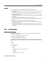
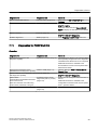
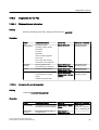
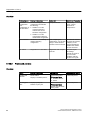
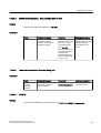
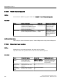
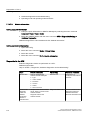
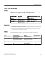
3.2.4.1
Backing up configuration data
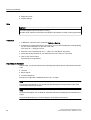
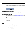
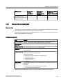
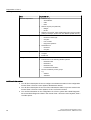
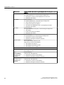
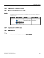
Data backup options
SIMATIC BATCH offers several options for backing up and restoring project data.
Data
Menu command for backup
operation
Menu command for restore
operation
● Materials
Options > Backup
Options > Restore
● Libraries
You can find information on this
in the section "How to generate
a backup (Page 25)".
You can find information on this
in the section "How to restore
data from a backup (Page 27)".
(2)
(3)
Select batch(es), select Archive
in the shortcut menu
-
● Basic recipes
● Formula categories
● Formulas
● Rights and roles
● User settings (1)
● Project settings
● Completed batches
You can find information on this
in the section "How to archive
batches (Page 14)".
(1) "User settings" can/will only be backed up to a database copy.
(2) Save the data to an SBB file (compressed XML file).
(3) Restore the data from an SBB file (compressed XML file).
Additional information
● Manual Process Control System PCS 7; SIMATIC BATCH
3.2.4.2
How to generate a backup
Elements of the backup
You can back up all configured data with the Backup command. The backup includes the
following elements:
● Materials
● Libraries
● Basic recipes
● Formulas
Service support and diagnostics (V8.0)
Service Manual, 03/2012, A5E02779775-02
25
Ensuring Availability
3.2 Data backup
● Rights and roles
● Project settings
Rule
NOTICE
The follow applies when a backup is running:
Operator input cannot be executed on the BATCH client where a backup is being generated.
Procedure
1. In BatchCC, select the menu command Options > Backup.
2. If there are non-archived batches in the project, you must acknowledge the message dialog
for non-archived batches. In this case, click "OK".
The "Save as..." dialog box opens.
3. Enter the name of the backup file ("...".sbb) in the "File Name" input field.
4. Select the storage location for your backup file from the "Save to" input field.
5. Click on the "Save" button.
The backup file is generated.
Import/Export Assistant
Using the IEA, you can export/import the following batch objects to/from a file with the extension
*.sbx:
● Libraries
● Basic recipes
● Formula categories
The export is supported in SIMATIC BATCH V6.1 or higher.
Note
For reasons of performance, you should only export/import one recipe to/from a file when
exporting/importing large recipes.
Note
All referenced objects such as libraries, materials and formula categories are included in the
export.
All formulas that belong to a formula category are included in the export.
26
Service support and diagnostics (V8.0)
Service Manual, 03/2012, A5E02779775-02
Ensuring Availability
3.2 Data backup
Starting with the Import/Export Assistant (IEA)
● Start the export assistant from BatchCC by selecting the Options > Export menu command.
● Start the import assistant from BatchCC by selecting the Options > Import menu command.
Additional information
● SIMATIC BATCH Manual
3.2.4.3
How to restore data from a backup
Introduction
You can restore the data from a backup file and update the Batch process cell in the SIMATIC
BATCH Control Center (BatchCC).
Requirement
No Batch process cell is available in the BatchCC.
Reading a backup
1. In BatchCC, select the menu command Options > Restore.
The "Restore" dialog box opens.
2. Select the storage location for the backup file ("...".sbb).
3. Click "Open".
The backup file is loaded.
Updating the Batch process cell
1. Select the Batch process cell in the tree view of BatchCC.
2. Select the menu command Edit > Update Process Cell.
The "Batch Process Cell - ..." dialog box opens.
3. Click "OK".
The "Update Process Cell" dialog box opens.
4. Compare the columns "Current process cell" und "New process cell" line-by-line. Rearrange
them if necessary.
You can find additional information about this in the manual Process Control System PCS
7; SIMATIC BATCH.
5. Click "OK".
The "Updating Process Cell" dialog box opens and closes automatically when the update
is completed.
Service support and diagnostics (V8.0)
Service Manual, 03/2012, A5E02779775-02
27
Ensuring Availability
3.2 Data backup
Result
In BatchCC, the data from the backup file is entered into the batch database and made
available again to the plant.
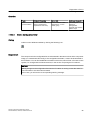
3.2.4.4
How to archive batches
Long-term archive
You archive batches in long-term archives in BatchCC. Long-term archives are used for longterm storage of batch data in accordance with the FDA.
Rules
● Only completed batches can be archived.
● Data from long-term archives cannot be used to restore defective batch data or batch
structures.
Requirement
The archiving technology is preset in BatchCC.
● Technology "Directory":
The archive data is saved to a shared network folder. SIMATIC BATCH does not use any
specific login or password settings for access to this folder.
● Technology "SQL Server":
The archive data is saved to an SQL database. Login and password are mandatory for this
technology; a specification of the domain is not used.
● Technology "FTP Server":
The archive data is saved to an FTP Server. Login and password are mandatory for this
technology; a specification of the domain is only required if the login is assigned to a domain.
For additional information, refer to the SIMATIC BATCH online help.
Archiving Individual Batches
You archive a single completed batch as follows:
1. Select the batches to be archived in the detail view.
2. Open the shortcut menu (by right-clicking) and select the menu command Archive.
Archiving multiple batches
You archive multiple completed batches as follows:
1. Open a Batch overview list from the "Details" shortcut menu.
2. Select the batches to be archived.
3. Right-click to open the shortcut menu and select the Archive menu command.
28
Service support and diagnostics (V8.0)
Service Manual, 03/2012, A5E02779775-02
Ensuring Availability
3.2 Data backup
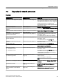
3.2.5
Backing up SIMATIC Route Control data
3.2.5.1
Backing up configuration data
Data backup options
SIMATIC Route Control provides the following options for backing up and restoring project
data.
● You can back up the project data from SIMATIC Route Control with a PCS 7 project.
For additional information, refer to the "How to archive a project (Page 17)" section.
● You can generate an image of the partition on which the project database is located.
● You can export/import the partial routes of SIMATIC Route Control.
For additional information, refer to the "How to back up project data from SIMATIC Route
Control (Page 29)" section.
Additional information
● Manual Process Control System PCS 7; SIMATIC Route Control
3.2.5.2
How to back up project data from SIMATIC Route Control
Introduction
This section describes the separate backup of partial routes from SIMATIC Route Control to
a file.
Note
You can back up the partial routes with the offline project data from SIMATIC Route Control.
The interface blocks are part of the PCS 7 project and are backed up during the archiving of
the PCS 7 project.
Preparing the database backups
Before performing a backup, you must always carry out the following steps in Route Control
engineering:
● Check the database consistency via the menu command Options > Check Consistency.
● Compress the database via the menu command Options > Compress Database.
Service support and diagnostics (V8.0)
Service Manual, 03/2012, A5E02779775-02
29
Ensuring Availability
3.2 Data backup
Creating a backup
1. Select the multiproject/project in the SIMATIC Manager.
2. Select the Options > SIMATIC Route Control> Engineering menu command.
The "Route Control Engineering - ..." dialog box opens.
3. Select the menu command Options > Export/Import CSV > CSV Export/Import Wizard ....
The "Wizard: CSV file data exchange (Export/Import)" opens.
4. Check the path in the "Directory" input box.
5. In the "Direction" group, activate the check box "RC project engineering >> CSV file(s)
(Export).
6. Click "Continue".
7. Select all check boxes.
8. Click "Continue".
9. Click "Finish".
The files are exported.
Additional information
● Manual Process Control System PCS 7; SIMATIC Route Control
3.2.5.3
How to restore data from a backup
Introduction
You restore partial routes from SIMATIC Route Control from a backup file.
Importing a backup
1. Select the multiproject/project in the SIMATIC Manager.
2. Select the Options > SIMATIC Route Control> Engineering menu command.
The "Route Control Engineering - ..." dialog box opens.
3. Select the menu command Options > Export/Import CSV > CSV Export/Import Wizard ....
The "Wizard: CSV file data exchange (Export/Import)" opens.
4. The dialog box "Wizard: CSV file data exchange (Export/Import)" opens.
5. Check the default path set in the "Directory" input box.
6. In the "Direction" group, activate the check box "CSV file(s) >> RC project engineering
(Import).
7. Click "Continue".
8. Select all check boxes.
9. Click "Continue".
10.Click "Finish".
The project engineering data are imported.
30
Service support and diagnostics (V8.0)
Service Manual, 03/2012, A5E02779775-02
Ensuring Availability
3.2 Data backup
Additional information
● Manual Process Control System PCS 7; SIMATIC Route Control
3.2.6
Creating an image
3.2.6.1
Backing up data by generating an image file
Introduction
It is advisable to generate an image file of the installation in order to backup partitions and
hard disk data (e.g. after reinstallation).
Image file
An image file maps all of the data on the backed-up medium (hard disk, logical drives). It is
used to back up data on partitions or hard disks. Many of the software packages that can be
used to generate image files also offer data compression.
Boot partitions are included in the backup. This enables you to save all the PC settings
including the Windows system settings.
All the data of a PC can usually be restored from an image file within a short amount of time
(e.g., 2 GB data takes approx. 10 minutes). In the event of a fault, you can restore the complete
PC installation.
Rules
● You must use the same hardware to restore data.
● Note the following settings of the hard disk for the image file
(you can find additional information on this in the section "Managing the operating system
(Page 91)"):
– Partition size
– Formatting of partition or hard disk (e.g., NTFS, FAT32)
● Authorizations and license keys cannot be included in the backup.
● The image software must be compatible with the current operating system.
Basic procedure
1. Move the authorizations and license keys to another medium (diskette, partition, etc.) before
generating the image.
2. Follow the instructions of the manufacturer of the image software when creating an image.
Service support and diagnostics (V8.0)
Service Manual, 03/2012, A5E02779775-02
31
Ensuring Availability
3.3 Hardware update
Additional information
● Documentation relating to the image software used
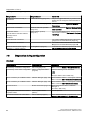
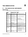
3.2.7
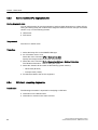
Comparing project versions
3.2.7.1
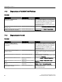
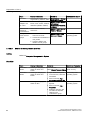
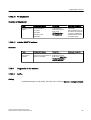
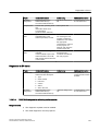
Comparing project versions with VXC
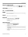
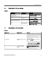
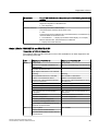
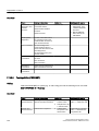
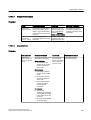
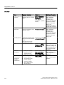
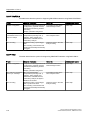
Version Cross Manager (VXM)
The Version Cross Manager is a separate application you can order as an option. You use the
Version Cross Manager to compare two user programs for download-relevant differences
quickly and reliably. This allows you to detect whether changes have been made to the user
program, and what those changes are.
Overview
Comparison of
Detailed
information
Called with
Additional information
Changes to different project
versions in the user program
CFC charts
In the Siemens SIMATIC programs
Start menu: STEP 7 > VXM Compare Versions
Configuration manual Process
SFC charts
User programs based on
XML files
(for synchronizing processcontrol project data with
planning data, for example)
CFC charts
Version Cross Manager
Online help
SFC charts
● XML file generated with
File > Export....
3.3
Hardware update
3.3.1
Hardware updates
Control System PCS 7;
Engineering System
Online help
Version Cross Manager
Version Cross Manager
● Compare XML files using File >
Compare With XML File....
Introduction
In this section, a hardware update refers to changing the firmware in SIMATIC modules.
Updating the firmware of a SIMATIC module is referred to as a "firmware update" in the
following.
A firmware update includes the following:
32
Service support and diagnostics (V8.0)
Service Manual, 03/2012, A5E02779775-02
Ensuring Availability
3.3 Hardware update
● Function upgrades
● Operating system enhancements
Released modules
You can find the firmware versions for modules released of a particular PCS 7 version in the
"PCS 7 - Released Modules" documentation that corresponds to the version in question.
Requirements for the firmware update
A firmware update for a SIMATIC module may be required if you wish to use new functions or
correct errors.
Checking the latest product version or the firmware version of a module
You need to check the latest product version or the firmware version of a module in the following
situations:
● When replacing a module (due to a defect, for example)
● When you wish to use new functions after you have change the configuration
Compare the PCS 7 - Released Modules documentation for the older PCS 7 versions to find
out which PCS 7 version first included the feature.
Determining the product version or the firmware version
Update-capable modules:
● You can find the following identifiers on update-capable modules:
– The product version is indicated by a cross (in the following example: product version
6).
– The original version of a firmware is indicated with text (in the following example: V3.0.2).
Example:
CPU 416-2
X 7
8 9
416-2XK02-0AB0
V3.0.2
● When a firmware update is delivered you obtain a label showing the current firmware
version which you can paste over the displayed label. After having completed the firmware
update, replace the module label accordingly to identify the valid FW version. This will
ensure uniformity in the plant documentation.
Modules that cannot be updated:
Service support and diagnostics (V8.0)
Service Manual, 03/2012, A5E02779775-02
33
Ensuring Availability
3.3 Hardware update
● If only the manufacturer can perform changes to a module, only the product version is
shown on the housing of the module (indicated by a cross; in the following example: product
version 10).
Example:
PS 407 10A
X 11
12 13
407-0KA01-0AA0
Recommendation for performing firmware updates
Perform these firmware updates at regular intervals when an opportunity presents itself (such
as during a scheduled plant shutdown).
Supply sources for the latest firmware version
You can request the update files for the latest firmware versions from your Siemens contact
partner, or download these from the Internet (http://support.automation.siemens.com). If you
cannot access the Internet address, contact Technical Support.
Note
The update file may be supplied in an executable, self-extracting file (.exe). When you want
to perform consecutive updates for different module types of module versions, you must unzip
the update files in separate folders for the different CPUs as follows:
● Type of module
● Product version
● Firmware version
Overview
The sections below describe topics related to hardware updates:
● Adjustments after a hardware change (Page 35)
● Updating a SIMATIC S7 CPU (Page 35)
● Updating an interface module IM xxx (Page 39)
● Updating a CP xxx (Page 41)
● Working with GSD files (Page 48)
34
Service support and diagnostics (V8.0)
Service Manual, 03/2012, A5E02779775-02
Ensuring Availability
3.3 Hardware update
3.3.2
How to make adjustments after a hardware change
Basic procedure
A change to the hardware always requires a change to the software. Configure the hardware
changes in HW Config. Compile the changes and then download the data to the CPU. You
can then physically replace, remove or add the modified hardware.
Procedure
1. Open the project (the AS) in HW Config.
2. Drag the object (such as the CPU: Type, Firmware Version x.x) from the hardware catalog
and drop it into the appropriate slot in the AS configuration table.
The following message appears: "Do you want to exchange component ... with
component ...?"
3. After verification, click "Yes" to confirm.
4. Select the menu command Station > Save/Compile.
You can also perform the compiling during the subsequent work.
3.3.3
Updating the CPU
Preparation
Compare the type and manufacture date of the modules you are using with the information in
the document PCS 7 Released Modules.
If replacement of the CPU is required, contact your Siemens representative.
Firmware update for CPU S7-400H
Note
In a fault-tolerant PCS 7 system, the (S7-400H) CPUs must always have a uniform hardware
version and the same firmware version.
Update capability of CPUs
The online update of the firmware can be performed using the procedure described below as
of the following firmware versions:
● CPU S7-400H as of firmware version 4.5
As of firmware version 4.5, the firmware can be updated in RUN mode.
● CPU S7-400 as of firmware version 5.0
Service support and diagnostics (V8.0)
Service Manual, 03/2012, A5E02779775-02
35
Ensuring Availability
3.3 Hardware update
You always need a memory card for a firmware update for older CPUs.
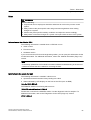
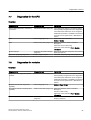
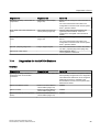
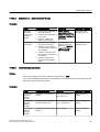
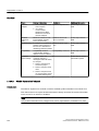
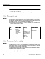
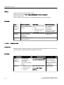
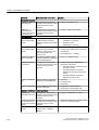
3.3.3.1
Components
Update CPU S7-400
Update CPU S7-400H
PC with external EPROM burner or programming
device for programming the memory card
X
X
Memory Card Flash-EPROM; 8 MB
X
X
STEP 7
X
X
Files for the firmware update (available on the
Internet).
X
X
How to perform a firmware update for the CPU (as of V5.0)
You are provided with several files (*.UPD) with the latest firmware to update the firmware of
a CPU. Download these files to the CPU. You do not need a memory card for the online update.
However, it is still possible to perform a firmware update with a memory card.
Preparation
Compare the type and manufacture date of the modules you are using with the information in
the document PCS 7 Released Modules.
If replacement of the CPU is required, contact your Siemens representative.
Requirements
● STEP 7 V5.3 or higher is installed on the programming device or PC.
● The update file for the firmware update is available on the programming device/PC.
● The CPU, whose firmware is to be updated, must be accessible online, for example, via
PROFIBUS, MPI or Industrial Ethernet. The files containing the latest version of the
firmware are available in the file system of your programming device or PC. A folder may
only contain the files for one firmware version.
Note
For CPUs with a PROFINET interface, you can update the firmware via Industrial Ethernet
on the PROFINET interface. Updating via Industrial Ethernet is significantly faster than
MPI or DP (depending on the configured baud rate).
You can update the firmware of the other CPUs via Industrial Ethernet, if the CPU is
connected to Industrial Ethernet via a CP.
36
Service support and diagnostics (V8.0)
Service Manual, 03/2012, A5E02779775-02
Ensuring Availability
3.3 Hardware update
Procedure in HW Config
To update the firmware of a CPU, proceed as follows:
1. Open the station with the CPU to be updated in HW Config.
2. Select the CPU.
3. Select the menu command PLC > Update Firmware.
4. Select the path to the firmware update files (CPU_HD.UPD) by clicking the "Browse" button
in "Update Firmware" dialog.
Once you have selected a file, information about which modules and which firmware
versions are suited for the file is displayed in the lower fields of "Update Firmware" dialog.
5. Click "Run".
STEP 7 checks whether the selected file can be interpreted by the CPU and loads the file
to the CPU if the result is positive. If the operating state of the CPU must be changed to do
this, you are prompted by dialogs to take action.
Procedure in SIMATIC Manager
The procedure corresponds to the one in HW Config; the menu command here is also "PLC
> Update Firmware". However, STEP 7 only checks if the module supports the function at the
time it is executed.
Note
Protecting the update process
There a digital signature, which is checked during the update of the CPU to protect the
firmware update. If an error is detected, the old firmware remains active and new firmware is
discarded.
Values received after the update of the firmware are retained
Once the CPU memory has been reset, the following values are retained:
● The parameters of the MPI interface (MPI address and highest MPI address).
● The IP address of the CPU
● The device name (NameOfStation)
● The subnet mask
● The static SNMP parameters
Updating a CPU with an operating system update card
You can find information on this at the following Internet address:
http://www.siemens.automation.com/service (http://support.automation.siemens.com/WW/
view/en/2774118)
Service support and diagnostics (V8.0)
Service Manual, 03/2012, A5E02779775-02
37
Ensuring Availability
3.3 Hardware update
3.3.3.2
How to perform a firmware update for the H-CPU (as of V4.5)
The firmware version can be changed using the online functionality as of firmware version
V4.5.x.
● Firmware update of an H system in RUN
● It is not possible to downgrade in RUN
Performing the firmware update of a H-CPU in RUN as of V4.5
Generally, a firmware version can only be upgraded to the next higher firmware version when
a firmware update in RUN is performed. It is not possible to downgrade in RUN. You should
also read the information provided in the version-specific description.
To update the firmware of the CPU of an H system in RUN, follow these steps:
1. Make sure that the H system is in the redundant state without errors.
2. Select one of the CPUs in HW Config or SIMATIC Manager.
3. Select the menu command PLC > Update Firmware.
The "Update Firmware" dialog box opens. Both CPUs are displayed with order number,
current firmware version, name and mounting position.
4. Select the firmware file to be loaded to the CPUs.
5. After confirmation with the "Run" button, a dialog with the following content opens:
"Caution ... all CPU data will be deleted. Do you want to continue?".
Click "Yes".
6. You can activate "Automatically continue" in the next dialog.
Click "Next". The firmware update starts in the "Run" state.
7. The firmware update is finished on both CPUs.
Check the operating mode and the active firmware version of both CPUs.
Downgrading an H-CPU
If a CPU in your S7-400H, fails, order a new CPU with the same number. This comes with the
latest firmware version. This firmware can be higher than the predecessor CPU. In this case,
the new CPU must be set to the older firmware version.
1. Insert the new CPU into your automation system.
Note
Do not connect the fiber-optic cable to the CPU of an H system.
2. Select this CPU in HW Config or SIMATIC Manager.
3. Select the menu command PLC > Update Firmware.
The "Update Firmware" dialog box opens.
4. Select the firmware file that corresponds to the version of the predecessor CPU.
38
Service support and diagnostics (V8.0)
Service Manual, 03/2012, A5E02779775-02
Ensuring Availability
3.3 Hardware update
5. Download this file to the CPU. The new CPU now has the same firmware version as the
previously used CPU.
6. Now connect the fiber-optic cable for the CPU of an H system.
Switch the system to the "Redundant" operating mode by starting this CPU.
You can then upgrade both CPUs of the H system to the latest firmware in the "Run" state.
Difference of the firmware update to a non-redundant system
Following the actual firmware update, a self-test starts automatically for the H-system. This
function may take several minutes. This time period depends on the amount of load memory
(size of the inserted memory card) and the amount of working memory.
Updating an H-CPU with an operating system update card
You can find additional information on this at the following Internet address:
http://www.automation.siemens.com/service (http://support.automation.siemens.com/WW/
view/en/6741018)
3.3.4
Updating an interface module
3.3.4.1
Updating an interface module (IM)
Introduction
The interface modules (IM) ) are the interface to the PROFIBUS DP in PCS 7.
Preparation
● Compare the type and version of the interface modules you are using with the information
in the document PCS 7 Released Modules.
● If replacement of the interface module is required, contact your Siemens representative.
● A firmware update is possible for some interface modules. You will find the procedure in
the section "How to perform a firmware update of an IM (Page 40)" below.
Update capability of interface modules or couplers downstream from interface modules
You can update the firmware of the following components (interface modules or couplers
downstream from interface modules):
Components
Order Number
IM 153-2
6ES7 153-2Bx00-0XB0
IM 152-1
6ES7 152-1AA00-0AB0
Service support and diagnostics (V8.0)
Service Manual, 03/2012, A5E02779775-02
As of firmware version
V2.02
39
Ensuring Availability
3.3 Hardware update
Components
Order Number
Y-Koppler
6ES7 197-1LB00-0XA0
Y-Link
6ES7 197-1LA01-0XA0
DP/PA-Link
6ES7 157-0AA82-0XA0
As of firmware version
V4.x
Firmware update for SIMATIC stations with redundant interface modules
Note
You can perform a firmware update of the interface modules for SIMATIC 400H station with
redundant interface modules during runtime.
3.3.4.2
How to perform a firmware update of an interface module (IM)
Introduction
This section provides a description of the update of the firmware for interface modules
(Interface Module (IM)) via Industrial Ethernet.
Requirements
The following is required to perform the update via Industrial Ethernet:
● STEP 7 V5.3 or higher is installed on the programming device or PC.
● The update file for the firmware update is available on the programming device / PC.
● The CP 443-1 is routing-capable (check in HW Config: Properties of the CP > brief
description "Routing" is listed).
● The files containing the current (new) version of the firmware is available in the file system
of your programming device or PC.
● The IM has been integrated in your PCS 7 project.
Procedure
1. Open SIMATIC Manager.
2. In the component view, select the SIMATIC station in which the IM is located.
3. Double-click the "Hardware" object in the detail window.
HW Config opens.
4. Select the IM whose firmware you want to update.
5. Select the menu command PLC > Update Firmware.
The "Update Firmware" dialog box opens.
6. Make the settings in accordance with the table below.
7. Click "Execute". The firmware is updated.
40
Service support and diagnostics (V8.0)
Service Manual, 03/2012, A5E02779775-02
Ensuring Availability
3.3 Hardware update
Settings in the "Update firmware" dialog box
Setting
Action
Location of the
firmware file
In the "Firmware File" group, specify the folder where you placed the file for
the firmware update. If you want to search, you can use "Browse" to open
Explorer.
Activation of "new"
firmware
Use the "Activate firmware after download" check box to specify when the
"new" firmware is to be activated as follows:
● Select the "Update firmware after download" check box if the IM is to
perform an automatic RESET after the new firmware was successfully
loaded. The new firmware is active following the restart.
● Clear the "Update firmware after download" check box to prevent the IM
from performing a RESET reset the new firmware was loaded. The "new"
firmware becomes active only after the power supply has been switched
off.
Firmware update in a redundant system
After the firmware update of the active IM, the "RESET" automatically triggers the switchover
of the two IMs.
You can now update the second IM in the redundant system. Each IM must be updated
separately.
Updating the identifier
Note
After the firmware update of the IM has been successfully completed, update the identifier of
the firmware version. You can find information on this in the section "Hardware Updates
(Page 32)".
3.3.5
Updating a CP xxx
3.3.5.1
Updating a communication processor (CP)
Introduction
In PCS 7, communication modules (CPs) are used to connect a SIMATIC station to bus
systems. By updating the firmware, you can enhance the CP properties without replacing the
hardware.
Service support and diagnostics (V8.0)
Service Manual, 03/2012, A5E02779775-02
41
Ensuring Availability
3.3 Hardware update
Update capability of CPs
The specific properties of a module are retained when there is a firmware update. The CP type
is not changed by a firmware update.
CP type
Update capability
CP 341
Can be updated in all versions
CP 443-1
Can be updated in all versions
CP 443-5 Extended
Can be updated in all versions
Order number
Overview
The sections below describe procedures for updating firmware:
● CP 341 firmware update (Page 42)
● CP 443-1 firmware update (Page 43)
● CP 443-5 Extended firmware update (Page 45)
3.3.5.2
How to perform a firmware update of the CP 341
Introduction
This section explains how to update the CP 341 firmware.
Preparations
● Compare the type and version of the modules you are using with the information in the
document PCS 7 Released Modules.
● If you need to replace the CP, contact your Siemens representative.
Requirements for the firmware update
● STEP 7 V5.3 or higher is installed on the programming device or PC.
● The update file for the firmware update is available on the programming device / PC.
● The software package "Configuration package for point to point communication" as of V5.0
is installed (supplied with the CP).
● The valid parameter assignment is stored in HW Config and has been downloaded to the
CPU.
Procedure
1. Open SIMATIC Manager.
2. In the component view, select the SIMATIC station in which the CP 341 is located.
42
Service support and diagnostics (V8.0)
Service Manual, 03/2012, A5E02779775-02
Ensuring Availability
3.3 Hardware update
3. Double-click the "Hardware" object in the detail window.
HW Config opens.
4. Double-click on the CP whose firmware is to be updated.
The "Properties" dialog box of the CP opens.
5. Select the "General" tab.
6. Click "Parameters ...".
The dialog box for the configuration interface opens.
7. Select the menu command Options > Firmware Update ...
– If the CP is available, the firmware version of the current module firmware is indicated
(Vx.y.z).
– If there is no firmware on the CP, a message to that effect is displayed. This can occur,
for example, if the firmware update was aborted. The old firmware is deleted in this case.
You must download a firmware.
8. In the "Firmware File" group, specify the folder where you placed the file for the firmware
update. To search for this, open an Explorer window by clicking "Browse".
The version of the selected firmware is displayed under "Selected FW version".
9. Switch the CPU to STOP.
10.Click "Download Firmware" to start the download procedure to the CP.
11.Click "Download Firmware" to confirm the download procedure.
If you click "Cancel", the download is aborted. The module will not be operational if this
happens.
Restart the firmware download to make the module operational again.
Note
Before deleting the older firmware, the CP checks if the order number of the firmware to be
downloaded is permitted.
Result
The new firmware is installed in the operating system memory of the CP. The progress of the
installation is indicated by a progress bar and a percentage under "Done". Once the firmware
update is complete, the module is ready for immediate operation.
3.3.5.3
How to perform a firmware update of the CP 443-1
Preparation
● Compare the type and version of the modules you are using with the information in the
document PCS 7 Released Modules.
● If you need to replace the CP, contact your Siemens representative.
Service support and diagnostics (V8.0)
Service Manual, 03/2012, A5E02779775-02
43
Ensuring Availability
3.3 Hardware update
Requirements for the firmware update
● STEP 7 V5.3 or higher is installed on the programming device or PC.
● The update file for the firmware update is available on the programming device/PC.
● Ethernet card (CP 1613, 3COM network adapter, for example)
Determining the MAC address of the CP 443-1
When updating firmware, you must know the current MAC address of the CP 443-1.
1. Open SIMATIC Manager.
2. In the component view, select the CP 443-1 for which the firmware is to be updated from
below the SIMATIC station.
3. Select the CPU > Diagnostics/Settings > Module Information.
4. Click "Special Diagnostics".
The NCM S7 diagnostics tool opens.
Note
If the NCM S7 diagnostics do not start, the connection between the programming device/
PC and the CP 443-1 is faulty. Correct the fault.
5. Note the MAC address setting of the CP 443-1 under "Industrial Ethernet".
Performing the firmware update
NOTICE
Note the following:
● A warning message appears before the download operation begins if an incorrect CP type
has been inadvertently addressed. The firmware can nevertheless be downloaded to an
incorrect CP type if the message is acknowledged.
● With the next steps, all data on your CP are deleted and cannot be recovered!
● Do not cancel a download operation once it is started. The CP may no longer be usable
if you do this and you will have to send it in for repair.
1. In the Siemens SIMATIC programs Start menu, select: STEP 7 > NCM S7 Industrial
Ethernet > Firmware Loader.
The dialog box of the firmware loader opens.
2. Click "Continue".
3. In the "Step 1" dialog box, set the path for the update file:
– Click "Browse".
– Use "Select file" to select the desired file ("<drive>:\TEMP\Cp4435ba.fwl", for example).
– Click on the "Open" button.
4. Click "Continue".
44
Service support and diagnostics (V8.0)
Service Manual, 03/2012, A5E02779775-02
Ensuring Availability
3.3 Hardware update
5. In the "Step 2" dialog box, set the MAC address.
6. Click "Continue".
7. Check the following settings:
– "Application access point"
– "Interface parameter assignment used"
8. Make sure that the correct settings have been activated in the configuration console.
Note
The access point must be set to "S7ONLINE CP xxxx(ISO)".
9. Activate the firmware update by clicking "Download".
10.Check whether the open *.fwl file includes the required firmware update for the CP.
Procedure when a download error occurs
If the download operation was terminated by an error, no LED is lit on the CP.
1. Switch the power supply of the rack off and on again.
2. Repeat the load operation.
If the CP responds to the download start, but the download operation does not finish properly,
it could be that:
● The same address has been assigned more than once on the plant bus.
● The load on the plant bus is too high.
Note
If a CP does not respond to a load procedure via the configured MAC address, load the CP
again via the imprinted address.
3.3.5.4
How to perform a firmware update of the CP 443-5 Extended
Preparation
● Compare the type and version of the modules you are using with the information in the
document PCS 7 Released Modules.
● If you need to replace the CP, contact your Siemens representative.
Service support and diagnostics (V8.0)
Service Manual, 03/2012, A5E02779775-02
45
Ensuring Availability
3.3 Hardware update
Requirements for the firmware update
● STEP 7 V5.3 or higher is installed on the programming device or PC.
● The update file for the firmware update is available on the programming device / PC.
● MPI cable
Note
Ensure the following for the firmware update of the CP 443-5 Extended:
● If you want to connect devices that operate with PROFIBUS standard DPV1 to your
PCS 7 system after conversion, you might have to replace the hardware (e.g. CP type:
6GK7 443-5DX03-0XE0 with firmware V5.1 or higher).
● This hardware requires special device drivers.
For information on generating the device drivers, refer to the Process Control System
SIMATIC PCS 7; Programming Instructions, Creating Blocks for PCS 7 documentation.
Preparing for the firmware update
1. Make sure that the required firmware update files are available on the programming device
or PC.
Files for the firmware update are available on the Internet. You can find information on this
in the section "Hardware Updates".
2. Switch off the power supply (PS) of the rack where the CP is inserted.
3. Use an MPI cable to establish a direct connection between the MPI interface of your
programming device or PC and the PROFIBUS interface of the CP.
4. Switch on the power supply of the rack and the programming device or PC.
5. In the Siemens SIMATIC programs Start menu select: SIMATIC NET > Set PG/PC
Interface.
You use this to establish the access path to the CP 443-5 Extended.
Example: Make the following setting for the CP 5611 (FWL):·
– Select "FWL_LOAD" as the "Application access point" to the CP 443-5 Extended.
– Select the MPI interface with the supplement "(FWL)" as the interface.
6. Click "OK".
7. Make sure there are no active applications on your programming device.
8. Restart the interface.
46
Service support and diagnostics (V8.0)
Service Manual, 03/2012, A5E02779775-02
Ensuring Availability
3.3 Hardware update
Performing the firmware update
NOTICE
Note the following:
● With the next steps, all data on your CP are deleted and cannot be recovered!
● Do not cancel a download operation once it is started. The CP may no longer be usable
if you do this and you will have to send it in for repair.
1. In the Siemens SIMATIC programs Start menu, select: STEP 7 > NCM S7 > Firmware
Loader.
The dialog box of the firmware loader opens.
2. Click "Continue".
3. In the "Step 1" dialog box, set the path for the update file
– Click the "Browse" button.
– Use "Select file" to select the desired file ("<drive>:\TEMP\Cp4435ex.fwl", for example).
– Click on the "Open" button.
4. Click "Next" to confirm the next three dialog boxes until you reach "Step 4: Perform Load
Operation".
5. Read the information in the dialog box for "Step 4: Perform Load Operation".
In the table below you will find the download operation states that are displayed.
6. Switch off the power supply of the rack.
7. Click "Cancel" to close the dialog box.
8. Reestablish the original PROFIBUS connection.
9. Switch on the power supply for the module.
The CP performs a self-test and is then ready for operation.
States of the download operation
Where
Display
State
On the PG/PC in the
The bar in the dialog box changes.
Firmware Loader dialog box
Download procedure is running.
On the PG/PC in the
The message "Download completed
Firmware Loader dialog box successfully" is displayed.
Download procedure is
complete.
CP 443-5 Extended
The CP RUN LED flashes.
Download procedure is running.
CP 443-5 Extended
The CP STOP LED is lit.
Download procedure is
complete.
Service support and diagnostics (V8.0)
Service Manual, 03/2012, A5E02779775-02
47
Ensuring Availability
3.3 Hardware update
Procedure when a download error occurs
If the download operation was terminated by an error, no LED is lit on the CP.
1. Switch the power supply of the rack off and on again.
2. Repeat the load operation.
3.3.6
Working with GSD files
3.3.6.1
Working with GSD files
Introduction
STEP 7 Version 5 applies a more stringent test to the GSD files (GSD = Device Master
dataFfile). Syntax errors or non-interpretable errors can occur with GSD files from an older
project, however.
Improved help texts are provided for syntax errors and GSD problems starting with STEP 7
Version 5.1 SP2.
If the following measures are not successful, contact the device manufacturer and request a
new GSD file. You can find solutions for some errors in this table:
48
Service support and diagnostics (V8.0)
Service Manual, 03/2012, A5E02779775-02
Ensuring Availability
3.4 Software update
Troubleshooting
When Error
Occurs
Error message
Source of Error
Remedy
During insert
operation
The 'SIMATIC 400(1) station'
does not support the
transmission rate of '187.5 kbps'
of the 'MBK-P' node.
The entry '187.5_supp = 1' is
not present.
1. Contact the device
manufacturer.
Install a new
GSD
The path\file name of the GSD
file contains a syntax error.
Vendor_Name: the number of
characters between the
quotation marks must not
exceed 32; special characters
are not allowed.
1. Create a backup copy of the file
and open it with a text editor
(such as WordPad)
The decimal separator in the
transmission rate must be
entered as a period and not as
a comma.
1. Create a copy of the file.
File cannot be interpreted.
Determine the
names of the
GSD files and
the path:
The 'SIMATIC 400(1)' station
does not support the
transmission rate of '187.5 kbps'
of the "MBK-P' node.
via the object
properties of the
DP slave
2. Check Vendor_Name.
3. Make corrections to the name,
save the file and link it again.
2. Open the original file with a text
editor (such as WordPad). In
transmission rate, change
'187,5_supp = 1' to
'187.5_supp = 1').
3. Start HW Config, select menu
command Options Update
catalog.
Remarks:If the entry '187.5_supp =
1' is not present, the transmission
rate is not supported. Contact the
device manufacturer.
3.4
Software update
3.4.1
Software updates
Information
● For additional information on the update of the PCS 7 software, refer to the
– Process Control System PCS 7; Software update without utilization of new functions
– Process Control System PCS 7; Software update with utilization of new functions
● For additional information on updating redundant operator stations at runtime, refer to the
PCS 7 Process Control System; Fault-Tolerant Process Control Systems manual, "Guide
to updating a redundant OS at runtime" section.
A corresponding brief overview is provided in the"Updating the PCS 7 OS in runtime
(Page 50)" section of this documentation.
● Information on installing hot fixes are included in the respective software package with the
hot fix.
Service support and diagnostics (V8.0)
Service Manual, 03/2012, A5E02779775-02
49
Ensuring Availability
3.5 Updating the PCS 7 OS in runtime
Note about software updates
Note
Note that you must use the appropriate hardware in order to take advantage of features in
new software versions.
You can find information on the minimum requirements for PC stations in PCS 7 in the manual
PCS 7 Process Control System; PC Configuration and Authorization.
3.5
Updating the PCS 7 OS in runtime
Introduction
You have the option of updating a redundant PCS 7 OS configuration at runtime in order to
adapt the "older" version of your current PCS 7 process control system to a "newer" PCS 7
version.
Updating the PCS 7 OS involves the following tasks:
● Preparatory measures
● Installation of the "new" software
● Commissioning measures required to adapt your existing PCS 7 process control system
Updating the PCS 7 OS during running operation offers the following benefits:
● Operation of the PCS 7 system is not disrupted.
● The AS does not enter STOP mode.
● The automation process can still be operator controlled and monitored.
Updating a redundant OS during operation
You can find more information about this in the documentation Process Control System PCS
7; Fault-tolerant Process Control Systems, Guide to Updating a Redundant OS During
Operation.
50
Service support and diagnostics (V8.0)
Service Manual, 03/2012, A5E02779775-02
Configuring diagnostics conditions
4.1
4
Requirements for diagnostics
Requirements
Several requirements must be fulfilled to ensure that the status of a PCS 7 system can be
diagnosed effectively. The most important requirements are:
● Diagnostics are enabled for the components.
● Diagnostic options were activated during configuration
Information on configuring the diagnostic options
The primary configurations can be found in the following documentation:
● Configuration manual Process Control System PCS 7; Engineering System
● Configuration manual Process Control System PCS 7; Operator Station
● Process Control System PCS 7; Maintenance Station function manual
● Manual SIMATIC; SIMATIC PDM (Process Device Manager)
You can search for information in the index of these manuals by entering "Diagnostics ..." as
a key word.
Checking PC components
● You check PC components using software tools of PCS 7 (such as a maintenance station
or PC DiagMonitor) and the operating system.
● The following configuration actions assist you in diagnosing PC components:
Configured element
Reference
Lifebeat monitoring
Configuration manual Process Control System PCS 7;
Diagnostic screen for PC diagnostics
Configuration manual Process Control System PCS 7;
Operator Station
WinCC "System Info" channel
Online help for WinCC Information System,
"Communication > System Info"
Diagnostics for systems with redundant
OS PCs
Configuration manual Process Control System PCS 7;
Operator Station
Operator Station
Checking module properties
1. Open the project in the SIMATIC Manager.
2. In the component view, select the SIMATIC station.
Service support and diagnostics (V8.0)
Service Manual, 03/2012, A5E02779775-02
51
Configuring diagnostics conditions
4.1 Requirements for diagnostics
3. Double-click the "Hardware" object in the detail window.
HW Config opens.
4. Double-click the module you wish to check.
The properties dialog box for the selected module opens.
5. Browse the individual tabs for appropriate options.
Activate the diagnostic properties depending on the module type.
Available diagnostic options can be found in the following tabs:
– Diagnostics"
– Inputs"
– Outputs"
– Options"
SIMATIC modules with diagnostic properties
The following components are available in PCS 7 diagnostic-capable modules:
● S7-400
● S7 300 modules
● ET 200M
● ET 200S
● ET 200iSP
● ET 200pro
● DP slaves
● DP/AS-i link
● Diagnostic repeaters
● Network components (SCALANCE; OSM, ESM)
Additional information
● Online help PC DiagMon
52
Service support and diagnostics (V8.0)
Service Manual, 03/2012, A5E02779775-02
Message concept of PCS 7
5.1
5
Servicing a system - message concept
Introduction
The message system and diagnostic options of PCS 7 help you to assess the system status.
You can find information about the PCS 7 message concept in the following sections:
● PCS 7 message system (Page 54)
● Origin of a message (Page 55)
● Determining the source of a message (Page 56)
● Evaluating and understanding messages (Page 57)
Basic terms
Some basic terms used in the PCS 7 message concept are defined in the following:
Term
Events
Definition
Events lead to a change in the data status in the automation system.
For example, an event can be the following:
A bit is modified in an automation system by a change to a process value, or after a
specified limit value was reached.
The configuration determines which events trigger a message.
Messages
Messages are triggered by events or by a message frame. PCS 7 has the following
message types:
● Operator input messages
● Process messages
● Operating messages
● Process control messages and system messages
Error and
fault
In PCS 7, the PCS 7 Operator Station operator control and monitoring system is also
used to display errors and faults in the process.
● Error: component (object) status that does not disturb the process (for example,
defective display lamps).
● Fault:component (object) status that interferes with the process (for example, a
defective motor).
Service support and diagnostics (V8.0)
Service Manual, 03/2012, A5E02779775-02
53
Message concept of PCS 7
5.2 PCS 7 message system
Additional information
You can find detailed information about the message system as follows:
● In the WinCC Information System:
Select the Start menu command under the SIEMENS SIMATIC products WinCC
Information System, and look under "System Overview > How WinCC Works >
– Message system of a PCS 7 OS
– Archive system of a PCS 7 OS
– Reports system of a PCS 7 OS
● In the configuration manual PCS 7 Process Control System; Operator Station, in the section
"Settings for the alarm system"
● In the online help for SIMATIC BATCH, you will find the following information under "Batch
Data Management":
– Batch reports
– Archiving batches
● In the SIMATIC Route Control online help, you will find the following information under
"Operator Control and Monitoring":
– Route log
5.2
PCS 7 message system
PCS 7 message system
PCS 7 acquires data on the status of your process and process control system using blocks
assigned with appropriate parameters. You can influence the response to an event with a
suitable program.
The most important message systems of PCS 7 are:
● WinCC operator control and monitoring system
● SIMATIC BATCH batch data management
Both message systems are available on the PCS 7 OS in process mode (runtime).
Configuration of messages in the message lists of PCS 7 OS
Every process message displayed on a PCS 7 OS always includes the following information:
● Date
● Time
● Origin
● Event
● Message Class
You can achieve the following when configuring messages:
54
Service support and diagnostics (V8.0)
Service Manual, 03/2012, A5E02779775-02
Message concept of PCS 7
5.3 Origin of a message
● Specify the status used to report an event
● Use the "Alarm Logging" editor on the PCS 7 OS to modify the selection of message
information to be displayed in WinCC
Message accuracy for signal transitions
Note
Be aware of the accuracy of the message system.
If events are recorded within one scan cycle, they can appear in the wrong order in the
message list.
Remedy: You can find information about this in the function manual Process Control System
PCS 7; High-precision Time Stamping.
Additional information
You can find detailed information on configuring messages in the following manuals:
● Configuration manual Process Control System PCS 7; Engineering System
● Configuration manual PCS 7 Process Control System; Operator Station
5.3
Origin of a message
Message path
Messages can originate in different locations in PCS 7 depending on the configuration. Each
message is given a time stamp. The event which causes a time stamp to be assigned to a
message depends on the place where the message has originated. Irrespective of where they
Service support and diagnostics (V8.0)
Service Manual, 03/2012, A5E02779775-02
55
Message concept of PCS 7
5.4 How to determine the source of a message
originate, all messages are handled in the same way regarding how they are displayed and
archived on the PCS 7 OS.
2ULJLQRID3URFHVV0HVVDJH
3URFHVVVLJQDOIDXOW\
$6&3
&38
3ODQW%XV
26&3
0HVVDJH
9LVLDOL]DWLRQ
Figure 5-1
$
$ODUP
$
$UFKLYLQJ
$
The letter "A" in the picture symbolizes an alarm message in PCS 7.
Additional information
You can find information on configuring messages in the following documentation:
● Configuration manual Process Control System PCS 7; Engineering System
● Configuration manual Process Control System PCS 7; Operator Station
For information on configuring messages with enhanced time stamp accuracy, refer to the
PCS 7 Process Control System; 10 ms Time Stamping function manual.
5.4
How to determine the source of a message
Procedure
1. Enable the message list by clicking
2. "Activate/Deactivate Autoscroll".
56
Service support and diagnostics (V8.0)
Service Manual, 03/2012, A5E02779775-02
Message concept of PCS 7
5.5 Understanding messages
3. In the message list, select the message for which you need additional information.
4. Click "Open Infotext".
5. Note the message number and use "Alarm Logging" to determine the source of the
message.
5.5
Understanding messages
5.5.1
Introduction
Overview
You can find important information for understanding the PCS 7 message concept in the
following sections:
● Message types in message lists and archives (Page 58)
● Target groups of messages (Page 58)
● Message lists in process mode (Page 59)
● Overflow of message buffer (Page 60)
● Message priorities (Page 61)
● Influencing messages (Page 62)
Service support and diagnostics (V8.0)
Service Manual, 03/2012, A5E02779775-02
57
Message concept of PCS 7
5.5 Understanding messages
5.5.2
Message types in message lists and archives
Message types in message lists and archives
Messages are divided into the following classes:
Term
Definition
Operator Input
messages
Operator Input messages are generated when an operator controls process
variables, for example, changes the operating mode of a controller.
● SIMATIC PCS 7 generates operator input messages automatically if you
use faceplates prepared from the libraries.
● If you configure faceplates according to the programming guide Process
Control System PCS 7; Creating Blocks for PCS 7, PCS 7-conforming
operator input messages are also available for your own blocks.
Process messages
Process messages signal process events that take place in the automated
process, such as limit value violations and operating messages.
● Process messages are predefined for the blocks and therefore do not
need to be configured. Message texts and message priority can be
modified as needed in the object properties for the CFC blocks. These
modifications can also be made centrally in the process object view or
by means of import/export operations.
● Operating messages are a subgroup of process messages. They signal
process values that can be used to evaluate a process-related
component, such as an operating hours counter.
Process control
messages
Process control messages are generated when SIMATIC PCS 7 detects and
signals errors in components within its own system. Such errors range from
failure of a component to a wire break message for a connected I/O signal.
Process control messages are generated by the driver blocks in PCS 7 and
do not need to be configured.
System messages
System messages are messages that are triggered by self-diagnostics of a device. System
messages are usually included in the process control messages or process messages
(operating messages).
5.5.3
Target groups of messages
Target Groups
58
Message type
Target group:
Process
management
Target group:
Operations
management and
recording
Target group: System
specialist and
maintenance specialist
Operator Input messages
X
X
X
Process messages
X
X
X
Service support and diagnostics (V8.0)
Service Manual, 03/2012, A5E02779775-02
Message concept of PCS 7
5.5 Understanding messages
Message type
Target group:
Process
management
Target group:
Operations
management and
recording
Target group: System
specialist and
maintenance specialist
Operating messages
X
X
X
X
X
Process control messages
System messages
5.5.4
X
Message lists in process mode
Message lists
PCS 7 places incoming messages in message lists. The message is available in different alarm
lists, depending on the event source and on the alarm status.
The following messages lists are available by default. You can modify these standard message
lists or create additional message lists.
Default message lists
List
Content
Incoming alarm list The incoming alarm list contains the alarms which require acknowledgment,
however, which are still pending acknowledgment or deactivation.
Acknowledged
alarm list
The acknowledged alarm list contains the acknowledged process alarms.
Outgoing alarm list The outgoing alarm list contains the alarms flagged as "Outgoing". Those alarms
are no longer active, but are not yet acknowledged.
History list
The history list provides a view of the alarm log which contains all alarms, except
the operator log.
Process control list The process control list provides a view of the alarm log, filtered according to
process alarms (and comparable ones).
Example: Rack failure
Process alarms are also displayed in the following lists:
● Incoming alarm list
● Acknowledged alarm list
● Outgoing alarm list
● History list
Operation list
The operation list provides a view of the alarm log. The operation list contains the
operator log.
Examples:
● The operator has set the controller setpoint to 5 bar
● The operator has activated the drive
The following figure illustrates the path a message takes through the message lists.
Service support and diagnostics (V8.0)
Service Manual, 03/2012, A5E02779775-02
59
Message concept of PCS 7
5.5 Understanding messages
$/$50/2*
,1&20,1*DODUP
,1&20,1*$/$50/,67
$OOXQDFNQRZOHGJHG
DODUPV
$FNQRZOHGJPHQW
$&.12:/('*('
$/$50/,67
287*2,1*DODUP
287*2,1*$/$50/,67
$FNQRZOHGJHGDFWLYH
DODUPV
$ODUPVFOHDUHGEHIRUH
DFNQRZOHGJPHQW
287*2,1*DODUP
$FNQRZOHGJPHQW
2SHUDWLRQ
9LHZVRIWKH
DODUPORJ
ILOWHUHGOLVWV
+,6725</,67
352&(66&21
752//,67
23(5$7,21/,67
Alarm log
All alarms, operator information and status changes are saved to the alarm log. You can use
the filters to read specific information from the alarm log.
5.5.5
Overflow of message buffer
Overflow of message buffer
Each component of the overall PCS 7 system can process only a limited number of messages.
If more alarms are generated in a component (for example, an AS) within a particular time
frame than the component can process, some of these alarms will be lost. If this case, the AS
sets an overflow flag and the following event is reported at the PCS 7 OS: "NRMS7 Messages
Lost".
Note
If events that trigger messages change status in very quick succession, this can trigger a
message surge. The overview of the plant status can no longer be sufficiently ensured.
60
Service support and diagnostics (V8.0)
Service Manual, 03/2012, A5E02779775-02
Message concept of PCS 7
5.5 Understanding messages
Additional information
You can prevent a message surge by activating the "Messaging Triggered by
Acknowledgment" function. You can find information on configuring in the configuration manual
Process Control System PCS 7; Engineering System.
5.5.6
Message priorities
Changing message priorities
In PCS 7, a priority can be assigned to each message. 0 is the lowest priority and 16 the highest
priority. When a signaling block is newly generated, its messages initially have the lowest
priority (0).
You can change the message priority in a variety of ways:
● In the object properties for the block
● In the process object view
● Via an import operation
Rules
● Message priorities can only be specified if you defined the message number range as
"Unique for Entire CPU".
● In PCS 7 OS, the unacknowledged message with the highest priority is always displayed
in the message row above the overview. If multiple messages have the same priority, the
most recent message is displayed here.
● You can filter the list according to priority.
Additional information
You can find information about configuring message priorities in the configuration manual
Process Control System PCS 7; Operator Station.
Service support and diagnostics (V8.0)
Service Manual, 03/2012, A5E02779775-02
61
Message concept of PCS 7
5.5 Understanding messages
5.5.7
Influencing messages
Options
PCS 7 offers the following options for influencing messages:
● Message suppression
– You can suppress individual block messages with the CFC configuration.
– In process mode, you can suppress individual messages directly in the faceplate using
the "Suppress message" check box.
● Locking and releasing messages for blocks and OS areas
Locking (and releasing) messages for blocks and OS areas is used when the plant operator
wants to lock all messages of an interrupt-capable block or OS area.
● Hiding and displaying messages
You hide individual messages to reduce the number of messages displayed in process
mode. The messages are entered in a history list. The following variations are used to hide
and display messages in PCS 7:
– Manual hiding and showing of messages in process mode
– Automatic hiding and displaying of messages in process mode
Additional information
● Configuration manual Process Control System PCS 7; Operator Station
● Configuration manual Process Control System PCS 7; Engineering System
● Manual Process Control System PCS 7 OS Process Management
62
Service support and diagnostics (V8.0)
Service Manual, 03/2012, A5E02779775-02
Failure - What next?
6.1
6
Activities in the event of a fault
Basic procedure in the event of a fault
1. Evaluate the messages with regard to the following aspects:
– Time
– Sequence
– Source
2. Determine the location and area of the fault.
Note
If the components you are using do not have diagnostics capability, only secondary faults
are signaled.
– Use diagnostic tools to analyze the fault. You can achieve the following with the
diagnostic tools:
You can find the cause of a fault.
or
You can verify the presumed cause of a fault.
– You can find the following information in the section "Diagnostics for PCS 7" for support:
The diagnostic tools available for PCS 7
Applications for the various diagnostic tools according to subsystem
Note
Make use of skilled experts if you cannot find a solution to your problem based on
available information. For information on this topic, refer to the section "Additional
support (Page 11)" of this documentation.
3. Determine the actions to be taken.
In a running plant, check if a stop is necessary.
NOTICE
Note the following information:
● The following actions may only be carried out by qualified personnel and in compliance
with valid statutory provisions and plant-specific rules:
– Changes to the configuration
– Replacement of and changes to components
● Bear in mind that uncharacteristic situations can occur in the plant after activation.
Make sure the activation of components and secondary systems is carefully directed.
Service support and diagnostics (V8.0)
Service Manual, 03/2012, A5E02779775-02
63
Failure - What next?
6.2 Preparing for expert support
Examples of causes
Fault
Possible causes
Initial diagnostics
CPU fault
● Fault due to internal error
CPU diagnostics
● Fault due to external error
CP fault
● Fault due to internal error
● Fault due to external error
Module Diagnostics > Special
Diagnostics > NCM S7 Diagnostics
CP... >
Information from:
● Module" folder
● Operating mode" folder
● Diagnostic buffer" folder
I/O module
fault
● Fault due to SIMATIC station component
● Fault due to external influences (such as
a short circuit on the module terminals)
Module diagnostics > Status
information and, if available,
diagnostic information
PC
component
fault
If the PC is running:
If the PC is defective:
● Fault due to events
● Repair/replace
● Faulty connections
● Restore data
6.2
Preparing for expert support
6.2.1
Information on cause of fault
Introduction
Topic area
Information
Supporting
service experts
● WHAT?:Actions for making essential information available to experts for fault
analysis.
● WHEN?:If expert support is needed in the event of a fault, you facilitate the work
of the experts by providing them essential information on the plant or the faulty
components.
● HOW?: You can find information on this in this section.
64
Service support and diagnostics (V8.0)
Service Manual, 03/2012, A5E02779775-02
Failure - What next?
6.2 Preparing for expert support
Overview
You support the work of service experts by providing them with information:
● Service experts need information about your plant and the faulty system in order to provide
quick support.
For additional information, refer to the "Plant documentation (Page 65)" section below.
● Service experts need information from the diagnostic buffer of the CPU in order to analyze
the cause of a CPU fault.
For additional information, refer to the "How to read the CPU diagnostic buffer (Page 66)"
section below.
● A memory dump facilitates the analysis of the cause of the CPU fault.
For additional information, refer to the "CPU fault - preparing diagnostics (Page 66)" section
below.
● Backing up the diagnostics files facilitates the analysis of an OS fault.
For additional information, refer to the "How to back up the diagnostic data of the PCS 7
OS (Page 68)" section below.
● You can take all measures necessary to enable remote diagnostics via "remote access".
For additional information, refer to the "Remote diagnostics of a PCS 7 system (Page 69)"
section below.
6.2.2
Plant documentation
Maintaining system information
Information on the components of your system is among the most important information
needed for successful repair.
You need this information in the following situations:
● When you are planning maintenance
● When you contact the hotline for assistance
Continual maintenance of this information shortens downtimes in case of a fault. Therefore,
always keep up-to-date lists (in a database or in a table, for example) containing the following
data:
● Plant
● Unit
● Location in plant
● Components
● Versions
– Hardware (version, in case of replacement)
– Firmware
– Software
– Libraries used in the S7 program
Service support and diagnostics (V8.0)
Service Manual, 03/2012, A5E02779775-02
65
Failure - What next?
6.2 Preparing for expert support
6.2.3
How to read the CPU diagnostic buffer
Saving diagnostic data
You can make it easier for service engineers to perform initial diagnostics on a faulty CPU by
saving and having ready the contents of the diagnostic buffer as service data (as of firmware
version V4.0) or in the following formats:
● HEX format
● TXT format
Requirement
The CPU is in STOP mode.
Procedure
1. Select the faulty CPU in the SIMATIC Manager.
2. As of firmware version V4.0:
Select the menu command CPU > Save service data.
Specify the storage location and name. Save the files.
3. Select the menu command PLC > Diagnostics/Settings > Module Information.
The "Module Information - Online" dialog box opens.
4. Select the "Stacks" tab and read out the following system memory:
– Block stack (B stack)
– Interrupt stack (I stack)
5. Provide these data to the service engineers.
6.2.4
CPU fault - preparing diagnostics
Introduction
The following information is important for analyzing a CPU fault:
● Information on the affected CPU
● Information or actions in the event of a fault
66
Service support and diagnostics (V8.0)
Service Manual, 03/2012, A5E02779775-02
Failure - What next?
6.2 Preparing for expert support
Rules
WARNING
Note the following:
● Only trained service employees should be authorized to work on the process control
system.
● Always observe the plant-specific rules and government regulations when making
changes to a system.
● Observe the plant-specific boundary conditions and adjust the work accordingly.
● Always bear in mind that changes in a system can impact other sections of the system.
Information on the affected CPU
The following information is needed when a CPU fault occurs:
● Order number
● Firmware version
● Hardware version
If you can access the CPU from the engineering station, you can query this information via the
module information. For additional information, refer to the "Module information (Page 112)"
section.
Note
A constantly updated list of all module information facilitates troubleshooting in the event of
a fault and reduces the time needed for correcting the fault.
Information in the event of a fault
The following information is needed if a fault occurs:
● Operations and actions/event history leading to the fault
● Status indicated by LED displays on the front of the CPU (such as RUN)
Only the RUN LED is lit
The SIMATIC station is functioning without errors.
RUN LED and additional red LED is lit
Faults have occurred in the SIMATIC station. Use the diagnostic tools for analysis. For
additional information, refer to the "Diagnostics for the CPU (Page 81)" section.
STOP LED is lit
Service support and diagnostics (V8.0)
Service Manual, 03/2012, A5E02779775-02
67
Failure - What next?
6.2 Preparing for expert support
● If the STOP LED is lit, read out the diagnostic buffer. For additional information on
procedures, refer to the "How to read the CPU diagnostic buffer (Page 66)" section
Save the diagnostics buffer to a HEX file and to a TXT file!
● These data can be analyzed by trained service engineers. They contain information about
the cause, for example:
– I/O error
– Synchronization error with an H-CPU
● If the possibility exists that a hardware error in the I/O caused the CPU to switch to STOP
mode, save the diagnostic buffer of the relevant module and the associated bus interface
module (for example, CP 443-5).
● Generate a memory dump.
All LEDs are off or are flashing
You recognize the "CPU defective" status by the following LED displays on the front of the
CPU:
● All LEDs are flashing.
● All LEDs are off, even though the power supply is switched on.
For additional support, contact your Siemens representative or Technical Support. Have the
"information in the event of a fault" indicated above ready.
6.2.5
How to back up the diagnostic data of the PCS 7 OS
Basic procedure
We recommend that you back up the diagnostic files for analysis of the cause of the OS fault
by experts.
Back up the diagnostic folder
1. Close WinCC.
2. Back up all diagnostic folders of WinCC
(default: [Installation path]\Siemens\WinCC\Diagnostics).
3. Give this information to the service employees.
You can back up the diagnostic files using the shortcut menu command Save to >
Compressed (zipped) Folder.
Note
Once the diagnostic files are backed up (not in diagnostic folder), you can delete the
content of the diagnostic folder. In this way, you avoid keeping old information in the new
diagnostic files.
If the same error occurs the next time you start WinCC, make an additional backup to help
the experts. Only a few messages will need to be analyzed in this backup.
68
Service support and diagnostics (V8.0)
Service Manual, 03/2012, A5E02779775-02
Failure - What next?
6.2 Preparing for expert support
6.2.6
Remote diagnostics of a PCS 7 system
Options for remote diagnostics and remote administration of a PCS 7 plant
We recommend you use the operating system features "NetMeeting" for remote diagnostics
of PCS 7 plants and for administrative access on PC stations with Windows XP Professional
and Windows 2003.
You can find additional information on this in the operating system's online help.
(VWDEOLVKLQJDFRQQHFWLRQYLDWKH
ಮ1HWPHHWLQJಯSURJUDP
&XVWRPHU6XSSRUW
6HUYLFH3HUVRQDO
7&3,3RU0RGHP
3&6WDWLRQLQ
3&63ODQW
7&3,3RU0RGHP
Transmission paths
The data can be transmitted along the following routes:
● Telephone line (modem)
● TCP/IP connection (system-internal network connection)
Security requirements
If you wish to perform remote diagnostics in a PCS 7 plant, you need to protect the this plant
against unauthorized access.
Several measures are required to realize a security concept. Optimal protection is only
provided with all security measures as a whole.
For additional information, refer to the whitepaper Safety concept in PCS 7 and WinCC - Base
document.
Service support and diagnostics (V8.0)
Service Manual, 03/2012, A5E02779775-02
69
Failure - What next?
6.2 Preparing for expert support
6.2.7
Interactive operator control and monitoring with the OS Web Option
Interactive operator control and monitoring of a PCS 7 plant using the OS Web Option
Use the OS Web Option for interactive control and monitoring of a PCS 7 plant.
For additional information, refer to the Process Control System PCS 7; OS Web Option manual.
The figure below shows how the OS Web Option (OS Web server, Web client) can be used in
a PCS 7 plant.
:HEFOLHQW
6RIWZDUH
3&6b:HEFOLHQW
,QWUDQHW,QWHUQHW
26FOLHQW
26FOLHQW:HEVHUYHU
6RIWZDUH
3&6:HE6HUYHU
/LFHQVHV
6HUYHUOLFHQVHV
26FOLHQW
7HUPLQDOEXV
(QJLQHHULQJ
VWDWLRQ(6
26VHUYHU
26VHUYHU
3ODQWEXV
$XWRPDWLRQ
6\VWHP$6
Transmission paths
The data can be transmitted along the following routes:
● Telephone line (modem)
● TCP/IP connection (system-internal network connection)
● Internet
70
Service support and diagnostics (V8.0)
Service Manual, 03/2012, A5E02779775-02
Failure - What next?
6.2 Preparing for expert support
Security requirements
If you use the OS Web Option in a PCS 7 plant, you must protect this plant against unauthorized
access.
Several measures are required to realize a security concept. Optimal protection is only
provided with all security measures as a whole.
For additional information, refer to the whitepaper Safety concept in PCS 7 and WinCC - Base
document.
Service support and diagnostics (V8.0)
Service Manual, 03/2012, A5E02779775-02
71
Diagnostics in PCS 7
7.1
7
Diagnostic capabilities in PCS 7 subsystems
Disclaimer of liability
WARNING
Siemens assumes no responsibility for inappropriate use of the instructions provided in this
documentation or any consequences that might result for the customer.
WARNING
Note the following:
● Only trained service employees should be authorized to work on the process control
system.
● Always observe the plant-specific rules and government regulations when making
changes to your system.
● Observe the plant-specific boundary conditions and adjust the work accordingly.
● Always bear in mind that changes in a system can impact other sections of the system.
Introduction
The message system and diagnostic tools of PCS 7 help you to assess the status of your
system. You can find information about the diagnostic tools In the following sections.
This description illustrates the capabilities of the diagnostic tools so that you can apply them
to your individual requirements.
● You will also find information on the fields of application for diagnostic tools.
● You will learn how to call up a diagnostic tool.
● Since malfunctions can have a variety of causes and because procedures for using the
diagnostic tools are already available in the online help, a detailed description is not
provided here.
Service support and diagnostics (V8.0)
Service Manual, 03/2012, A5E02779775-02
73
Diagnostics in PCS 7
7.1 Diagnostic capabilities in PCS 7 subsystems
Assessing the status of your process control system
Topic
Questions Answered
Diagnostics in PCS 7
Where can I perform a specific diagnostics operation?
Diagnostic tools
● Which diagnostic procedures can be performed with a diagnostic tool?
● How is the diagnostic tool activated?
● Where can I find a description of the diagnostic tool or diagnostic
capability?
Diagnostics
Diagnostics refers to all activities intended to:
● Ascertain the status of a system
● Find errors and faults as early as possible and identify their cause
Diagnostic messages
Diagnostic capabilities are used to analyze the system status and to determine the causes of
faults.
Overview of diagnostic tools
You can find information on using diagnostic tools, grouped according to areas of application,
in the following sections:
● Full Diagnostics Using the Maintenance Station (Page 75)
● Diagnostics for PC user settings (Page 77)
● Diagnostics for PC Components (Page 77)
● Diagnostics for Network Connections (Page 79)
● Diagnostics during Configuration (Page 80)
● Diagnostics for the CPU (Page 81)
● Diagnostics for Modules (Page 81)
● Diagnostics for PROFIBUS DP (Page 82)
● Diagnostics on PROFIBUS PA (Page 83)
● Diagnostics on PROFINET
● Diagnostics on Foundation Fieldbus
● Diagnostics for the OS (Page 84)
● Diagnostics for the BATCH station (Page 85)
● Diagnostics for the Route Control station (Page 86)
● Diagnostics for the time of day (Page 86)
For many components, you will find displays on the front panel indicating the status of the
component and any errors. Analyzing these displays enables you to obtain information without
intervening in the system. The additional product manuals you will need for this analysis can
be found in the section "Diagnostics for Hardware Displays (Page 87)".
74
Service support and diagnostics (V8.0)
Service Manual, 03/2012, A5E02779775-02
Diagnostics in PCS 7
7.2 Diagnostics with the maintenance station (asset management)
7.2
Diagnostics with the maintenance station (asset management)
Introduction
With PCS 7 V6.1 and higher, a PCS 7 system can be fully diagnosed with the help of the
maintenance station. The maintenance station is an operator station that is specially configured
and assigned parameters for use in diagnostic and maintenance functions.
We particularly recommend the use of a maintenance station in medium and large PCS 7
systems.
Maintenance station
With the maintenance station, PCS 7 enables you to call up information on the states of all
PCS 7 components on diagnostics screens which are hierarchically structured. As part of this
process, the data of a component are analyzed using the available online functions of the
associated tools. You can access ES data from the diagnostics screens (can be controlled via
access protection mechanisms).
Screens for process-control diagnostics can be generated automatically for the entire PCS 7
system and made available on the maintenance station. The top level forms an overview
screen for the entire system.
Diagnostics options
You will find information on the states of individual PCS 7 components with diagnostic capability
on the maintenance station's special diagnostics screens.
Area
Diagnostics for ...
Automation systems
● CPU
● SIMATIC PCS 7 BOX
● Distributed I/O, such as ET 200M, ET 200S,
ET 200iSP, ET 200pro, input and output modules
● Field devices (HART, PROFIBUS PA, ...)
● Redundancy
PC stations
–
Master/standby configuration
–
Status of redundant partners
● Operator stations
● BATCH stations
● Route Control stations
● Archive servers
● SIMATIC PCS 7 BOX
● SIMATIC Industrial PCs
● Standard PCs (also WebNavigator client or WebNavigator
diagnostic client via IP address)
● Redundancy for PC stations from PCS 7
Service support and diagnostics (V8.0)
Service Manual, 03/2012, A5E02779775-02
–
Master/standby configuration
–
Status of redundant partners
75
Diagnostics in PCS 7
7.2 Diagnostics with the maintenance station (asset management)
Area
Diagnostics for ...
Ethernet components
● Switches, e.g.:
–
SCALANCE X
–
OSM
–
ESM
● Network objects (via profile file)
–
Bridges
–
Router
● Network components, which enable diagnostics using the "NIB II"
profile (for example, printers and other SNMP-capable devices)
PROFIBUS components
● PROFIBUS DP
–
Interface modules (IM)
–
Couplers
–
Link modules
–
Diagnostic repeaters
● PROFIBUS PA
PROFINET components
–
Interfaces
–
Couplers
● Interface modules (IM)
● Couplers
● IE/PB-Link
Intelligent field devices
● HART field devices
● Field devices on the following fieldbus systems:
–
PROFIBUS DP
–
PROFINET
–
PROFIBUS PA
–
FOUNDATION Fieldbus
● Devices of different product groups
e.g.
–
SIPART
–
SITRANS
Additional information
● You will find a description of how to configure a maintenance station in the configuration
manual PCS 7 Process Control System; Maintenance Station.
● You will find a description of how to use the maintenance station in process mode in the
manual PCS 7 Process Control System; PCS 7 OS Process Control.
● You can find information on the configuration of a PCS 7 system with a Web Diagnostic
Server and Web Diagnostic Client in the manual PCS 7 Process Control System; PCS 7
OS Web Option.
76
Service support and diagnostics (V8.0)
Service Manual, 03/2012, A5E02779775-02
Diagnostics in PCS 7
7.4 Diagnostics for PC components
7.3
Diagnostics for PC user settings
Overview
Diagnostics for
Diagnostics tool
Called with
Defining users,
Windows User
setting authorizations for access Management (Page 93)
to files and folders
(Windows users and user groups)
Control Panel > Administrative Tools
> Computer Management > System >
Local users and groups
WinCC users
Open WinCC Explorer by selecting the
menu command Editors >
User Administrator > Open
User administrator
(Page 103)
PCS 7 users (user roles and
rights in PCS 7 applications)
Shares
7.4
In the Siemens SIMATIC programs
Start menu: SIMATIC Logon >
Configure SIMATIC Logon
Shares for drives, folders
and files (Page 92)
Control Panel > Administrative Tools
> Computer Management > System >
Shared Folders > Shares
Diagnostics for PC components
Overview
Diagnostics for
Diagnostics tool
Called via
Status of PC stations, redundancy
Maintenance Station (Page 75)
The maintenance station is an operator station
that is specially configured for use in diagnostics.
The maintenance station has to be configured.
Additional information is available in the
documentation Process Control System PCS 7;
Maintenance Station
PC configuration
Windows System Information
(Page 91)
Enter the following in the "Run" dialog of the
Start menu: msinfo32"
Note:
You can save the system information to a file.
1. Select in the Start menu under Options >
System Programs > System Information.
2. Select the menu command File > Save.
Functions of drivers, logs, and services
Managing the operating
system (Page 91) Event
displays
Control Panel > Administrative Tools >
Computer Management > System > Event
Viewer
Note: Only blue icons = "all correct"
Service support and diagnostics (V8.0)
Service Manual, 03/2012, A5E02779775-02
77
Diagnostics in PCS 7
7.4 Diagnostics for PC components
Diagnostics for
Diagnostics tool
Called via
Function of standard network modules
Set PC station (Page 94)
In the Siemens SIMATIC programs Start menu:
SIMATIC NET > Settings > Set PC Station
In the tree view, select PC Station > "Network
Module" modules > Softnet IE.
Click "Test".
Online verification of operating
capability of redundant OS components
Redundancy status display
(Page 106)
Picture must be configured and downloaded to
the OS.
Additional information is available in the
configuration manual Process Control System
PCS 7; Operator Station
Networks and network connections
For additional information, refer to the section
"Diagnostics for network connections
(Page 79)."
Security settings and patches
MBSA (Page 101)
Enter the following in the "Run" dialog of the
Start menu: "Mbscali.exe"
Printers and print jobs
Printers and print jobs
(Page 96)
In the Start menu in the settings for Printers and
Faxes
To obtain information about a print job, click on
the printer executing the job.
Installed versions of the PCS 7 software
Installed SIMATIC software
(Page 97)
In the Siemens SIMATIC programs Start menu:
SIMATIC > Product Information > Installed
Software
Language version of the PCS 7 software
● European language version:
__SIMATIC PCS 7 EU__
● Asian language version:
__SIMATIC PCS 7 CHS__
PCS 7 bundle PCs
PC DiagMonitor (Page 97)
PC DiagMonitor is started automatically on
bundle PCs when the PC starts up.
Operating system faults with Dr. Watson
error
Dr. Watson Log
Enter the following in the "Run" dialog of the
Start menu: drwtsn32"
Make the following settings:
● Select the "Visual Notification" check box.
● Windows XP SP2 allows the following:
Select "Full" (default setting "Mini") for the
"Crash Dump Type" option.
You can find additional information on the use
and the settings in the Microsoft "Help and
Support Center".
78
Service support and diagnostics (V8.0)
Service Manual, 03/2012, A5E02779775-02
Diagnostics in PCS 7
7.5 Diagnostics for network connections
7.5
Diagnostics for network connections
Overview
Diagnostics for
Diagnostics tool
Connections with diagnostic capability Maintenance Station (Page 75)
Called with
The maintenance station is an operator station
that is specially configured for use in diagnostics.
The maintenance station has to be configured.
Additional information is available in the
documentation Process Control System PCS 7;
Maintenance Station
Network configuration
NetPro (Page 97)
Network > Check Consistency
Established connections to SIMATIC
stations
NetPro (Page 97)
Select CPU: PLC > Activate Connection Status
Status of network cards on Industrial
Ethernet
Windows "Network Connections"
dialog (Page 99)
Control Panel > Network Connections
Connections to other stations; IP
address, MAC address
Command line input (Page 93)
Enter the following in the "Run" dialog of the
Start menu: "cmd"
Determining MAC addresses and
TCP/IP addresses
Command line input (Page 93)
Enter the following in the "Run" dialog of the
Start menu: "cmd"
Connection established to domain
servers:
Command line input (Page 93)
In the DOS window, enter 'ping IP address'
In the DOS window, enter ipconfig –all.
DHCP, WINS, DNS
Enter the following in the "Run" dialog of the
Start menu: "cmd"
In the DOS window, enter ipconfig –all.
PC station
Set PC Station (Page 94)
In the Siemens SIMATIC programs Start menu:
SIMATIC NET > Set PC Station
Redundant switches:
Observer function (Page 99)
Enter the following in the "Run" dialog of the
Start menu: "cmd"
● SCALANCE X-300
In the DOS window, enter TELNET . Additional
information in the Configuration Manual
● SCALANCE X-400
SIMATIC NET; Industrial Ethernet Switches
SCALANCE X-300 / X-400
Status of network components, status
of a WinCC application
Station Configuration Editor
(Page 95)
Configuration with HW Config and loading of PC
station required
Call: in the taskbar via the button:
Connections to intelligent field devices SIMATIC PDM (Page 114)
In SIMATIC Manager: Options > Set PG/PC
Interface
PC Ethernet modules
NCM S7 Industrial Ethernet
(Page 98)
In the Siemens SIMATIC programs Start menu:
STEP 7 > NCM S7 Industrial Ethernet >
Diagnostics
Status of configured channels and
their connections to the SIMATIC
station
WinCC - Channel Diagnosis
(Page 104)
In the Siemens SIMATIC programs Start menu:
WinCC > Tools > Channel Diagnostics >
"Channels/Connections" tab
Service support and diagnostics (V8.0)
Service Manual, 03/2012, A5E02779775-02
79
Diagnostics in PCS 7
7.6 Diagnostics during configuration
Diagnostics for
Diagnostics tool
Called with
Connections to the OS: faulty or
established
Lifebeat Monitoring (Page 101)
Call picture (@CONFIG.PDL) in process mode.
Status of process interface
Status of connections (Page 105)
In the WinCC Explorer: Options > Status of
Connections
Client-server connections
Status of multi-user operation
(Page 104)
In the WinCC Explorer: Options > Status of MultiUser Operation
Determine stations
BANY (add-on product)
(Page 117)
If you have installed BANYnet, call the program
with the menu command Start menu > Programs
> BANYnet.
Find IP address and MAC address
Picture must be configured and downloaded to
the OS.
Message frames
Collisions
PROFIBUS DP connections
You can find additional information in the section
"Diagnostics on PROFIBUS DP (Page 82)"
PROFIBUS PA connections
You can find additional information in the section
"Diagnostics on PROFIBUS PA (Page 83)".
Status of devices which support
SNMP (e.g., network switches)
7.6
PC DiagMonitor (Page 97)
In the Siemens SIMATIC programs Start menu:
PC DiagMonitor > Management Station
Diagnostics during configuration
Overview
Diagnostics for
Diagnostics tool
Called with
Consistency of hardware configuration
HW Config (Page 111)
Menu command Station > Check Consistency
Consistency of PC station configuration
Station Configuration Editor
(Page 95)
Click the following icon in the taskbar:
Analyze "Status" column table entry
Block consistency in a SIMATIC station
SIMATIC Manager (Page 109)
Select SIMATIC Station > S7 Program > Blocks
Menu command Edit > Check Block Consistency
Chart consistency in a SIMATIC station
SIMATIC Manager (Page 109)
Select SIMATIC Station > S7 Program > Charts
Menu command Edit > Check Consistency
Connection error
Module Information (Page 112) Select the SIMATIC station in SIMATIC
Manager or
the CPU in HW Config.
Open signal interconnections in PCS 7
Operator Station
PCS 7 operator station
(WinCC)
Convert pictures
Connection functions for a PC station
Set PC Station (Page 94)
In the Siemens SIMATIC programs Start menu:
SIMATIC NET > Settings > Set PC Station
80
Service support and diagnostics (V8.0)
Service Manual, 03/2012, A5E02779775-02
Diagnostics in PCS 7
7.8 Diagnostics for modules
7.7
Diagnostics for the CPU
Overview
Diagnostics for
Diagnostics tool
CPU module information, redundancy,
connections
Maintenance station (Page 75) The maintenance station is an operator station
that is specially configured for use in diagnostics.
Called with
The maintenance station has to be configured.
Additional information is available in the manual
Process Control System PCS 7; Maintenance
Station
CPU
HW Config (Page 111)
Select CPU: Menu command
Station > Online
CPU
Module Information (Page 112) Select the SIMATIC station in SIMATIC
Manager or
Select the CPU in HW Config.
Select the menu command PLC > Module
Information
Module displays
Evaluating the Module Display
(Page 87)
Notes on the manuals: Diagnostics for hardware
displays (Page 87)
CPU fault - preparing diagnostics
Only to support experts
CPU fault - preparing diagnostics (Page 66)
7.8
Diagnostics for modules
Overview
Diagnostics for
Diagnostics tool
Called with
Diagnostics of all diagnostic-capable
modules
Maintenance station (Page 75) The maintenance station is an operator station
that is specially configured for use in diagnostics.
The maintenance station has to be configured.
Additional information is available in the manual
Process Control System PCS 7; Maintenance
Station
Modules and CPs with diagnostics
capability
HW Config (Page 111)
Station > Open Online
I/O modules and CPs with diagnostics
capability
Module Information (Page 112) Select the SIMATIC station in SIMATIC
Manager or
the CPU in HW Config.
Select the menu command PLC > Module
Information
Module displays
Service support and diagnostics (V8.0)
Service Manual, 03/2012, A5E02779775-02
Evaluating the Module Display
(Page 87)
Notes on the manuals: Diagnostics for Hardware
Displays (Page 87)
81
Diagnostics in PCS 7
7.10 Diagnostics on PROFINET
7.9
Diagnostics for PROFIBUS DP
Overview
Diagnostics for
Diagnostics tool
Devices and connections with
diagnostic capability
Maintenance station (Page 75) The maintenance station is an operator station
that is specially configured for use in diagnostics.
Called via
The maintenance station has to be configured.
Additional information is available in the
documentation Process Control System PCS 7;
Maintenance Station
Internal PROFIBUS DP interface of the
CPU
Module Information (Page 112) Diagnostics via HW Config > Module Information
PROFIBUS DP error
PROFIBUS DP Diagnostics
With Diagnostic Repeater
(Page 113)
Diagnostics via HW Config > Module Information
Status of PROFIBUS nodes
NetPro (Page 97)
In the Siemens SIMATIC programs Start menu:
STEP 7 > NetPro
Select the menu command View > With DP
Slaves to display the DP slaves in the network
view
Status of stations
NCM S7 (Page 99)
In the Siemens SIMATIC programs Start menu:
STEP 7 > NCM S7 > Diagnostics
Station failure
SYSTEM Process Control
Diagnostics (add-on product)
(Page 119)
Picture must be configured and downloaded to
the OS.
Fault indication with detailed information
about cause of error
Name and comment from HW Config
PCS 7; Operator Station
Order number, addresses, slot types
Error on PROFIBUS
7.10
Additional information is available in the
configuration manual Process Control System
Amprolyzer (add-on product)
(Page 116)
Available if the Amprolyzer is installed.
Diagnostics on PROFINET
Overview
Diagnostics for
Diagnostics tool
Called via
Devices and connections with
diagnostic capability
Maintenance Station (Page 75)
The Maintenance Station is an operator station
that is specially configured for use in diagnostics.
The Maintenance Station has to be configured.
Additional information is available in the
documentation Process Control System PCS 7;
Maintenance Station
Internal PROFINET interface of the CPU Module information (Page 112)
Diagnostics via HW Config > Module Information
(only for CPU 41x- PNIO
82
Service support and diagnostics (V8.0)
Service Manual, 03/2012, A5E02779775-02
Diagnostics in PCS 7
7.11 Diagnostics for PROFIBUS PA
Diagnostics for
Diagnostics tool
Called via
Status of PROFINET stations
Topology Editor (Page 100)
Diagnostics via Edit > PROFINET IO >
Topology.
Status of PROFINET stations
NetPro (Page 97)
In the Siemens SIMATIC programs Start menu:
STEP 7 > NetPro
Select the menu command View > With DP
Slaves to display the DP slaves in the network
view
Status of stations
NCM S7 (Page 99)
In the Siemens SIMATIC programs Start menu:
STEP 7 > NCM S7 > Diagnostics
Fieldbus diagnostics
BANY (Page 117)
In the Programs > BANY PNIO Start menu
7.11
Diagnostics for PROFIBUS PA
Overview
Diagnostics for
Diagnostics tool
Called via
Devices and connections with
diagnostic capability
Maintenance Station (Page 75)
The Maintenance Station is an operator station
that is specially configured for use in diagnostics.
The Maintenance Station has to be configured.
Additional information is available in the
documentation Process Control System PCS 7;
Maintenance Station
Devices and connections on the
SIMATIC PDM (Page 114)
PROFIBUS PA with diagnostic capability
SIMATIC Manager: View > Process Device
Network View
Status of devices on the PROFIBUS PA
with diagnostic capability
NCM S7 (Page 99)
In the Siemens SIMATIC programs Start menu:
STEP 7 > NCM S7 > Diagnostics
Station failure
SYSTEM process control
diagnostics (add-on product)
(Page 119)
Picture must be configured and downloaded to
the OS.
Fault indication with detailed information
about cause of error
Name and comment from HW Config
PCS 7; Operator Station
Order number, addresses, slot types
Error on PROFIBUS
Service support and diagnostics (V8.0)
Service Manual, 03/2012, A5E02779775-02
Additional information is available in the
configuration manual Process Control System
Amprolyzer (add-on product)
(Page 116)
Available if the Amprolyzer is installed.
83
Diagnostics in PCS 7
7.13 Diagnostics for the OS
7.12
Diagnostics on FOUNDATION Fieldbus
Overview
Diagnostics for
Diagnostics tool
Called via
Devices and connections with
diagnostic capability
Maintenance Station (Page 75)
The Maintenance Station is an operator station
that is specially configured for use in diagnostics.
The Maintenance Station has to be configured.
Additional information is available in the
documentation Process Control System PCS 7;
Maintenance Station
Diagnostics of the FF Link (IM 153‑2 FF
and FDC 157)
Module information (Page 112)
Diagnostics via HW Config > Module Information
Devices and connections on Foundation
Fieldbus with diagnostic capability
SIMATIC PDM (Page 114)
SIMATIC Manager: View > Process Device
Network View
7.13
Diagnostics for the OS
Overview
Diagnostics for
Diagnostics tool
Called with
Operating capability of all OS
components and communication
connections
Maintenance station (Page 75)
The maintenance station is an operator station
that is specially configured for use in diagnostics.
The maintenance station has to be configured.
Additional information is available in the
documentation Process Control System PCS 7;
Maintenance Station
WinCC projects and the assigned
SIMATIC stations
Lifebeat monitoring (Page 101)
Connections between OS components
Simatic Shell (Page 101)
Windows Explorer (workstation):
Select PC station > "Simatic Shell" folder > in the
shortcut menu Properties
Connection between WinCC and AS
Status of connections
(Page 105)
In WinCC: Options > Status of Connections
Connection between OS server and OS
client
Status of multi-user operation
(Page 104)
In WinCC: Options > Status of Multi-User
Operation
Status of channels and connections to
the AS
WinCC Channel Diagnostics
(Page 104)
In the Siemens SIMATIC programs Start menu:
WinCC > Tools > Channel Diagnostics
Visual representation of redundancy
monitoring on OS client
Area overview (Page 105)
In WinCC: Area overview > "Status of the
connected server" icon
OS is in process mode
84
Call picture (@CONFIG.PDL) in process mode.
Picture must be configured and downloaded to
the OS.
Service support and diagnostics (V8.0)
Service Manual, 03/2012, A5E02779775-02
Diagnostics in PCS 7
7.14 Diagnostics for the BATCH Stations
Diagnostics for
Diagnostics tool
Called with
Operating capability of redundant OS
components
Redundancy status display
(Page 106)
Picture must be configured and downloaded to
the OS.
You can find information about this in the
configuration manual Process Control System
PCS 7; Operator Station
Time master role of the redundant OS
server
Time master role of the OS
server (status) (Page 106)
The tags "@TimeSyncDevice1State" and
"@TimeSyncDevice2State" need to be
configured on a faceplate. The OS must be
loaded.
General system information of an OS
server
WinCC "System Info" channel
(Page 102)
Picture must be configured and downloaded to
the OS.
You can find information about this in the
configuration manual Process Control System
PCS 7; Operator Station
OS fault - preparing diagnostics
Only to support experts
Status PCS 7 Web Server
7.14
You can find information on this in the section
"OS fault - preparing diagnostics (Page 68)".
Internet Explorer: http://
<server_address>.status.html
Diagnostics for the BATCH Stations
Overview
Diagnostics for
Diagnostics tool
Operating capability of all BATCH
components and communication
connections
Maintenance station (Page 75) The maintenance station is an operator station
that is specially configured for use in diagnostics.
Called with
The maintenance station has to be configured.
Additional information is available in the
documentation Process Control System PCS 7;
Maintenance Station
Status of the BATCH server
Status icons in the BATCH
server taskbar (Page 107)
Taskbar
Status of master
Status icons in the BATCH
server taskbar (Page 107)
Taskbar
Status of the standby server (partner
server)
Status icons in the BATCH
server taskbar (Page 107)
Taskbar
Service support and diagnostics (V8.0)
Service Manual, 03/2012, A5E02779775-02
85
Diagnostics in PCS 7
7.16 Diagnostics for time of day
7.15
Diagnostics for the Route Control stations
Overview
Diagnostics for
Diagnostics tool
Called with
Operating capability of all
SIMATIC Route Control
components and communication
connections
Maintenance station (Page 75)
The maintenance station is an operator station that is
specially configured for use in diagnostics.
Status of redundant servers
Status icons in the Route Control
server taskbar (Page 109)
Taskbar
Established connections to
SIMATIC stations
NetPro (Page 97)
NetPro: Online view > Select CPU: PLC > Activate
Connection Status
The maintenance station has to be configured.
Additional information is available in the
documentation Process Control System PCS 7;
Maintenance Station
7.16
Diagnostics for time of day
Overview
Diagnostics for
Diagnostics tool
Called with
AS-CPU time
SIMATIC Manager (Page 109)
Select CPU: PLC > Set Time of Day
AS-CPU time
Module Information (Page 112) Station > Open Online
PC time
Managing the operating
system (Page 91)
Control Panel > Date/Time. Do not change these
settings.
Activated time services
Windows System Utilities
Control Panel > Administrative Tools > Services
Select CPU: PLC > Set Time of Day
Select "Windows Time": Action > Properties
"General" tab > Startup type: ...
Synchronization status on the terminal
bus
Set PG/PC Interface (Page 94) In the Siemens SIMATIC programs Start menu:
SIMATIC NET > Set PG/PC Interface
Select interface > Click "Diagnostics" > In the
"Time" group
Configuration of time displayed in
WinCC Editor "Time
operator control and monitoring systems Synchronization"
86
Open WinCC Explorer with the menu command
Editors > Time Synchronization > Open
Service support and diagnostics (V8.0)
Service Manual, 03/2012, A5E02779775-02
Diagnostics in PCS 7
7.17 Diagnostics for hardware displays
7.17
Diagnostics for hardware displays
Overview
Many components have displays indicating the component status and errors. Analyzing these
displays enables you to obtain information without intervening in the system.
Components
You can find information about diagnostic options in the following manuals and
sections:
Power supply module
Reference manual SIMATIC;
Central module for
S7-400
Reference manual SIMATIC;
S7-400 Programmable Controller; CPU Data
● Monitoring functions of the CPU
● Status and error displays
● Operating mode switch
CPU
S7-400 Programmable Controller; Module Specifications
● Backup battery (optional)
● Error messages by means of LED displays
● Operator control and display elements
CP 441
Manual SIMATIC;
CP 441 Point-to-Point Communication - Installation and Parameter
Assignment
● Diagnostics for CP 441
CP 443-1
Device manual S7 CPs/Part B4;
CP 443-5 Extended
Device manual S7 CPs/Part B4;
Description of CP 443-1
● Displays and operating mode switch
Description of CP 443-5 Extended
● Displays and operating mode switch
S7-300 I/O modules
Reference manual SIMATIC;
S7-300 Programmable Controller; Module Specifications
● Diagnostic data for the signal modules
Additional information is available in the ET 200M Signal Modules for Process
Automation () manual or in the
ET 200M distributed I/O device HART analog modules () manual.
S7-300 fail-safe signal
modules
Manual SIMATIC;
Programmable Controller S7-300; Fail-safe Signal Modules
● Diagnostics of F-SM errors
● Properties, front view, connection and block diagram
S7-300
ex I/O modules
Manual SIMATIC;
Service support and diagnostics (V8.0)
Service Manual, 03/2012, A5E02779775-02
Programmable Controller S7-300, ET 200M s
ex I/O modules
● Digital input module: Properties
● Diagnostics for analog modules
● Module view and block diagram
87
Diagnostics in PCS 7
7.17 Diagnostics for hardware displays
88
Components
You can find information about diagnostic options in the following manuals and
sections:
ET 200M
Manual SIMATIC;
ET 200M Distributed I/O; Commissioning and Diagnostics
● Diagnostics by means of LED display IM 153-1, IM 153-2
● Diagnostics with STEP 7
ET 200iSP
Manual SIMATIC;
ET 200pro
Manual SIMATIC;
ET 200pro Distributed I/O System; Commissioning and diagnostics
● LED display ...
● Insertion and removal of modules
● Diagnostics with STEP 7
ET 200S
Manual SIMATIC;
DP/PA Coupler
Manual SIMATIC;
Bus couplers DP/PA- Link and Y-Link
Diagnostics by means of LED displays
● LED displays of the IM 157
● LED displays of the DP/PA coupler
● LED displays of the Y coupler
Y-Link
Information under DP/PA Coupler
FF Link
Manual SIMATIC;
Bus couplers FF- Link
AFD
(use on fieldbus PROFIBUS PA or
FOUNDATION
Fieldbus)
Manual SIMATIC;
SIMATIC NET; PROFIBUS PA
● Diagnostics by means of LED displays
● Diagnostic messages for electronic modules
AFS (use on fieldbus PROFIBUS PA or
FOUNDATION
Fieldbus)
Manual SIMATIC;
ET 200iSP Distributed I/O; Commissioning and Diagnostics
● Status and error LEDs on IM 151-2
● Insertion and removal of modules
● Line break of the NAMUR encoder on the digital input module
● Diagnostics with STEP 7
ET 200S Distributed I/O; Commissioning and Diagnostics
● Diagnostics by means of LED displays
● Diagnostic messages for electronic modules
SIMATIC NET; PROFIBUS PA
● Diagnostics by means of LED displays
● Diagnostic messages for electronic modules
Service support and diagnostics (V8.0)
Service Manual, 03/2012, A5E02779775-02
Diagnostics in PCS 7
7.17 Diagnostics for hardware displays
Components
You can find information about diagnostic options in the following manuals and
sections:
Diagnostic repeaters
Manual SIMATIC;
Diagnostic Repeater for PROFIBUS DP
● LED diagnostics
Switch for Ethernet
Operating Instructions SIMATIC NET;
Industrial Ethernet Switches SCALANCE X-400
● LED
Commissioning manual SIMATIC NET; Industrial Ethernet, SCALANCE X-100
and SCALANCE X-200 Product Line
● SCALANCE X<…> displays (SCALANCE X208 displays, for example)
Manual SIMATIC NET; Industrial Ethernet OSM/ESM
● Display and control elements
Status LEDs for PROFINET IO and PROFIBUS DP
Comparison of LEDs for diagnostics
The following table includes information on the LEDs available for an initial diagnostics and
the meaning of the LED.
LED
Meaning for PROFINET IO
Meaning for PROFIBUS DP
BUSF
Lit up in red:
Lit up in red:
Bus error (no physical connection to a
subnet/switch)
Bus error at interface (e.g. bus short-circuit)
Incorrect transmission rate
Full duplex transmission is not activated
Flashing:
Flashing:
The PROFINET device is a controller:
The module is a DP master:
Failure of a connected IO device
Failure of a connected station
At least one of the assigned IO devices
cannot be addressed
At least one of the assigned slaves cannot
be addressed
Incorrect configuration
Incorrect configuration
The PROFINET device is an IO device:
The module is a DP slave:
The watchdog time has expired.
The watchdog time has expired.
Bus communication via PROFINET is
interrupted.
Bus communication via PROFIBUS DP is
interrupted.
IP address is incorrect.
PROFIBUS address is incorrect.
Incorrect configuration
Incorrect configuration
Incorrect parameter assignment
Incorrect or missing device name
IO controller not available/turned off, but
Ethernet connection exists.
RX
Lit up in yellow:
Not available
Data is received via the interface.
The LED flickers when low data volumes
are transferred.
Service support and diagnostics (V8.0)
Service Manual, 03/2012, A5E02779775-02
89
Diagnostics in PCS 7
7.18 Diagnostic tools
LED
Meaning for PROFINET IO
Meaning for PROFIBUS DP
TX
Lit up in yellow:
Not available
Data is sent via the interface.
The LED flickers when low data volumes
are transferred.
LINK
Lit up in green:
Not available
Another device (most often a switch) is
connected and the physical connection
exists.
FO
Lit up in yellow:
Not available
The respective transmission path has to be
inspected.
End of form
7.18
Diagnostic tools
7.18.1
Diagnostics tools of PCS 7
Disclaimer of liability
WARNING
Siemens assumes no liability for improper use of the instructions provided in this
documentation and for any consequences that might result for the customer.
WARNING
Note the following:
● All work must be performed by trained service personnel.
● Always observe the plant-specific rules and government regulations when making
changes to your system.
● Observe the plant-specific boundary conditions and adjust the work accordingly.
● Always bear in mind that changes in a system can impact other parts of the system.
90
Service support and diagnostics (V8.0)
Service Manual, 03/2012, A5E02779775-02
Diagnostics in PCS 7
7.18 Diagnostic tools
7.18.2
Diagnostics for the PCs
7.18.2.1
Windows System Information
Calling
Enter the following in the "Run" dialog of the Start menu: "msinfo32".
Overview
Topic
Detailed information
Called with
Additional information
PC
configuration
Operating system
System Overview
Online help of the
operating system
System Overview >
Components > Display
Online help of the
operating system
Operating system version
PC NAME
Processor
BIOS data
Users currently logged on
Time zone
Size of the work memory
Information on the swap file
Graphics
settings
Type of graphics card
Printer
Display of existing printers
System Overview >
Components > Printer
Online help of the
operating system
Drives
Recognized internal and
external drives or storage
media
System Overview >
Components > Storage
> Drives
Online help of the
operating system
Called via
Additional information
Set resolution and frequency
Partitioning of hard disks
7.18.2.2
Managing the operating system
Calling
Called via Computer Management
Overview
Topic
Detailed information
Event display
Icons indicate status (specialist System Tools > Event
knowledge required for analysis) Viewer
Removable
memory
Recognized external drives or
storage media
Service support and diagnostics (V8.0)
Service Manual, 03/2012, A5E02779775-02
Select folder,
press "F1" - blue icon
only = "everything OK"
Data Memory >
Removable Media
91
Diagnostics in PCS 7
7.18 Diagnostic tools
Topic
Detailed information
Called via
Hard disks
Drive names, formats, size,
segmentation, partitions, status
Data Memory > Storage
Media Management
Additional information
Network
adapters and
PC cards
Network adapter type access
levels, users, servers, network
addresses (IP/MAC address)
System Tools > System
Information >
Components > Network
> Adapter
Network-wide
analysis of
connected PCs
Active users in network,
Active PCs
System Tools > Shared
Folders > Shares
Management of
users and user
groups
● Creation and modification of
local user accounts
System Tools > Local
Users and Groups
Online help of the
operating system
● Creation and modification of
user profiles
● Creation, addition and
deletion of local groups
7.18.2.3
Shares for drives, folders and files
Calling
Called via Computer Management > System
Overview
Topic
Detailed information
Called via
Additional information
Drives and
folders
Granting or changing of
shares for drives and
folders
In the tree view
Drives and
folders
Granting or changing of
shares for drives and
folders
● Open Windows Explorer
Select the folder,
Select Shared Folders > Share press "F1" key
● In the tree view, select the
drive/folder
Online help of the
operating system
● Menu command: File >
Properties > "Shares" tab
Files
Granting or changing of
shares for files
● Select the file in Windows
Explorer
Online help of the
operating system
● Menu command: File >
Properties
● Select the "Security" tab
and make the required
settings in the
"Permissions" group.
92
Service support and diagnostics (V8.0)
Service Manual, 03/2012, A5E02779775-02
Diagnostics in PCS 7
7.18 Diagnostic tools
7.18.2.4
System tools - Local Users and Groups
Overview
Topic
Detailed information
Called with
Additional information
Managing
users and
groups in the
operating
system
● Creation and modification of
local user accounts
Control Panel >
Administrative Tools >
Computer Management
> System > Local users
and groups
Online help of the
operating system
In the Siemens
SIMATIC programs
Start menu: SIMATIC
Logon > Configure
SIMATIC Logon
Online help for
Application
permissions
● Creation and modification of
user profiles
● Creation, addition and
deletion of local groups
● Standard users, language
and password changes
● Selection of the computer
from which the user data are
to be obtained
SIMATIC Logon
● Selection of the device via
which component logon is to
be checked
● Setting a delay time for
logging off from SIMATIC
Logon
7.18.2.5
Command line commands
Calling
Enter the following in the "Run" dialog of the Start menu: "cmd"
You can find additional information on the Windows commands named here by searching the
Microsoft "Help and Support Center".
Overview
Topic
Detailed information
Called via
Additional information
Connections
(network
adapter
function)
Verification of own network
adapter
Enter "ping localhost" or
Help and Support
Center
Connections
(network
adapter
function)
Verification of a connection to Enter "ping - {PC‑name}" or
another Ethernet node
"ping ‑ {IP‑address}"
Help and Support
Center
Connections
(network
adapter
function)
Identification of own network
adapter
Help and Support
Center
Service support and diagnostics (V8.0)
Service Manual, 03/2012, A5E02779775-02
"ping 127.0.0.0".
Enter "ipconfig"
93
Diagnostics in PCS 7
7.18 Diagnostic tools
7.18.2.6
Topic
Detailed information
Called via
Additional information
Connections
(network
adapter
function)
Identification of network
adapter of servers and
network services
Enter "ipconfig -all"
Help and Support
Center
Connections
(network
adapter
function)
Active connections,
Enter "netstat"
Help and Support
Center
computer I/Os,
Ethernet statistics
Set PC station
Calling
In the Siemens SIMATIC programs Start menu: SIMATIC NET > Settings > Set PC Station
Overview
Topic
Detailed Information
Called with
Additional information
Configuration
Detected modules
SIMATIC NET
Configuration > Modules
folder
Online help for Microsoft
Management Console; see
"Set PC station" topic
Diagnostic
options
Available options vary
for each module
SIMATIC NET
Configuration > Modules >
folder, select module.
Online help for Microsoft
Management Console; see
"Set PC station" topic
You can find additional
information in the online
help
7.18.2.7
Set PG/PC interface
Calling
Options:
● In the Siemens SIMATIC programs Start menu: SIMATIC NET > Set PG/PC Interface
● SIMATIC Manager via menu command Options > Set PG/PC Interface
94
Service support and diagnostics (V8.0)
Service Manual, 03/2012, A5E02779775-02
Diagnostics in PCS 7
7.18 Diagnostic tools
Overview
7.18.2.8
Topic
Detailed Information
Called with
Additional information
Time
synchronization
Synchronization status on
the PC's terminal bus
(requirement: CP 1613)
Select interface > Click
"Diagnostics" > In the
"Time" group
Online help for
Microsoft
Management
Console; see "Set PC
Station" topic
Station Configuration Editor
Calling
Call this on the Windows taskbar by clicking the following icon:
.
Requirement
The components in the configuration list must be entered in the same order as in the component
image you created with HW Config. If the configuration deviates, it cannot be downloaded to
the PC station. You can find additional information on this in the manual PCS 7 Process Control
System; PC Configuration and Authorizations, in the section "Preparing the PC stations".
NOTICE
Making changes to the configuration list when the PC station is running causes the entire PC
communication to be closed and restarted.
In this case, you will receive a corresponding warning message.
Service support and diagnostics (V8.0)
Service Manual, 03/2012, A5E02779775-02
95
Diagnostics in PCS 7
7.18 Diagnostic tools
Overview
Information on
Detailed information
Called with
Additional information
Hardware
configuration
and
configuration of
the PC station
The status display in the
configuration list indicates
the following:
Components" tab
Online help
Topic: "Status
Symbols for
Components"
● Whether or not the
created component
matches the current
hardware configuration
● Whether or not the
configuration matches a
downloaded configuration
Check module
Verification of accessibility of
modules following
configuration.
After completing the
configuration, you can click
"Ring" to check whether
modules can be accessed.
Provided the module
supports this function,
a display on the
module will indicate
whether the module
can be accessed.
PC station
Diagnostics for a PC station
Diagnostics" tab > Export
Requires expert
knowledge.
Save file
7.18.2.9
Consult an expert if
you encounter
problems with the
content of a log file
Printers and print jobs
Overview
Topic
Detailed information
Called with
Additional information
Printers and
devices
Device failure
Via the Start menu:
Printers and faxes
Online help via F1
Display of available printers
● Problem devices
● Printer
Pending print
jobs
96
Display of print jobs
Deletion of print jobs
Via the Start menu:
Printers and faxes
Online help via F1
Double-click the name
of the printer.
Service support and diagnostics (V8.0)
Service Manual, 03/2012, A5E02779775-02
Diagnostics in PCS 7
7.18 Diagnostic tools
7.18.2.10 PC DiagMonitor
Overview of DiagMonitor
Topic
Detailed information
Called with
Additional information
Preparing the PC
station
CPU temperature,
In the Siemens
SIMATIC programs
Start menu:
PC DiagMonitor >
PC DiagMonitor
Online help
Called via
Additional information
In the Siemens
SIMATIC programs
Start menu: SIMATIC >
Product Information >
Installed Software
Online help
fan speed,
hard disks,
operating hours
BIOS data
Only a SIMATIC PC can
be used as a monitored
computer. DiagMonitor
requires device drivers
for specific types.
7.18.2.11 Installed SIMATIC software
Overview
Topic
Detailed information
Installed versions Installed software and
of the PCS 7
versions, language version of
software
the PCS 7 software
7.18.3
Diagnostics in the network
7.18.3.1
NetPro
Calling
In SIMATIC Manager or HW Config, select the menu command Options > Configure Network.
Service support and diagnostics (V8.0)
Service Manual, 03/2012, A5E02779775-02
97
Diagnostics in PCS 7
7.18 Diagnostic tools
Overview
7.18.3.2
Topic
Detailed information
Called with
Additional information
Consistency of
configuration
Nodes that are not networked
(exception: MPI nodes that are
not networked) inconsistent
connections in subnets with
only one node
Network > Check
Consistency
Online help for STEP 7
"Checking the
consistency of the
network" topic
Connection
status
Established connections to
SIMATIC stations
Select CPU: PLC >
Activate Connection
Status
Connection
status
Established connections to PC
stations
Select PC stations: PLC
> Activate Connection
Status
Faults on
PROFIBUS
Only when a diagnostic
repeater is used
CPU > PROFIBUS >
Display Network
Topology
Status of DP
slaves
Display DP slaves in the
network view
View > With DP Slaves
NCM S7 Industrial Ethernet
Calling
In the Siemens SIMATIC programs Start menu: STEP 7 > NCM S7 Industrial Ethernet >
Diagnostics
Overview
Topic
Detailed information
Called with
Additional information
CP status
Dynamic information about
the operating mode of the
communication functions of
CPs connected online
Diagnostics > Online
> Open Connection
Online help for STEP 7,
topic: "Hardware
diagnostics"
Manual SIMATIC NET;
NCM S7 for Industrial
Ethernet
98
General CP
diagnostics and
statistics
functions
Operating mode
Diagnostics
functions
depending on CP
type and
operating mode
ISO transport connections
Scan event messages
recorded in the Ethernet CP
ISO-on-TCP connections
Diagnostics > Online
> Open Connection
Diagnostics > Online
> Open Connection
TCP connections
UDP connections
E-mail connections
Service support and diagnostics (V8.0)
Service Manual, 03/2012, A5E02779775-02
Diagnostics in PCS 7
7.18 Diagnostic tools
7.18.3.3
SIMATIC NET switches - SCALANCE X-300 / X-400
Calling
Called via the Web user interface or TELNET
Overview
Topic
Detailed Information
Called via
Additional information
Redundancy
Observer function fault
diagnostics and fault
protection for high speed
redundancy (HSR).
Enter the following in
the "Run" dialog of the
Start menu: "cmd"
Documentation
In the DOS window,
enter TELNET .
Additional information
in the documentation
SIMATIC NET; Industrial
Ethernet Switches
SCALANCE X-300 /
X-400
SIMATIC NET;
Industrial Ethernet
Switches SCALANCE
X-300 / X-400
7.18.3.4
"Network Connections" Windows dialog box
Overview
7.18.3.5
Topic
Detailed information
Called with
Additional information
Status of network
cards on
Industrial
Ethernet
Dynamic display of the status
of physical and virtual
network adapters
In the Start menu via the
Network Connections
Online help of the
operating system
NCM S7
Calling
In the Siemens SIMATIC programs Start menu: STEP 7 > NCM S7 > Diagnostics
Service support and diagnostics (V8.0)
Service Manual, 03/2012, A5E02779775-02
99
Diagnostics in PCS 7
7.18 Diagnostic tools
Overview
Topic
Detailed information
Called via
Additional information
General CP
diagnostics and
statistics
functions
Operating mode
General" tab
● Online help NCM
Diagnostics, Topic
"General diagnostic
functions"
Connected stations
Station-related statistics
functions
● Manual SIMATIC
NET; NCM S7 for
PROFIBUS
Station overview
Mode-specific
diagnostics
Dynamic information about
the operating mode of the
communication functions of
CPs connected online
FMS connections DP master diagnostics
Communication status of
slaves and call of data for DP
slave diagnostics
DP slave diagnostics (nonpassive slaves)
PROFIBUS
connections
DP master
DP slave
FDL connection
FMS connection
PROFIBUS
connections
Faults and inconsistencies in
FMS connections of the CP
PROFINET
connections
7.18.3.6
Topology Editor (PROFINET)
Calling
Select the PROFINET IO system (e.g. in HW Config) and call the following menu command:
Edit > PROFINET IO > Topology.
Overview
Topic
Detailed information
Called via
Additional information
Devices and
interconnections
Checking the configured
● "Table view" tab >
devices and interconnections
"Online" button
Online help for Topology
Editor > "Table view" tab
● "Graphic view" tab
> "Online" button
Devices and
interconnections
100
Offline/online comparison
● "Offline/online
comparison" tab >
"Start" button
Online help for Topology
Editor > "Offline/online
comparison" tab
Service support and diagnostics (V8.0)
Service Manual, 03/2012, A5E02779775-02
Diagnostics in PCS 7
7.18 Diagnostic tools
7.18.3.7
MBSA
Introduction
The Microsoft Baseline Security Analyzer (MBSA) is a tool for administrators that enables them
to check a Windows network for security vulnerability.
Overview
Topic
Detailed information
Additional information
Security
vulnerability
Configuration, passwords,
utilities, creation of security
reports, required updates
● Whitepaper Security concept PCS 7 and WinCC
7.18.4
Operator station diagnostics
7.18.4.1
Lifebeat monitoring
● MBSA description from Microsoft®
Overview
Topic
Detailed information
Called with
Additional information
Monitoring of
components of
WinCC projects
and their
associated
SIMATIC stations
Configured components
are displayed graphically in
a plant picture. Faulty
components have a red line
running through them in the
graphic.
Configure lifebeat
monitoring and
call the picture in
process mode
Online help for WinCC
Information System, "Lifebeat
Monitoring"
Information about
configuration in the
configuration manual Process
Control System PCS 7;
Operator Station
7.18.4.2
Simatic Shell
Calling
1. Select "My Computer" in the tree view of Windows Explorer.
2. Select the "Simatic Shell" folder.
3. Select the menu command Settings from the shortcut menu.
Service support and diagnostics (V8.0)
Service Manual, 03/2012, A5E02779775-02
101
Diagnostics in PCS 7
7.18 Diagnostic tools
Overview
Topic
Detailed information
Called via
Additional information
Network
adapters
● Network adapters of the
local computer
Network adapters" list
Online help of Simatic
Shell
Multicast service life
(TTL)" input line
Online help of Simatic
Shell
● "IP" column
current TCP/IP
addresses and MAC
addresses of the local
network adapters
Multicast
service life
(TTL)
Maximum number of route
jumps between subnets
("TTL" IP parameter)
Multicast proxy
IP address of a computer in
Multicast proxy" input
another subnet, which is to
line
be used as a substitute for
distributing Multicast packets
Compatibility
Compatibility mode for
communication between
different versions of WinCC
Computer
status change
When the status of a
computer changes, a
message is sent to all station,
for example:
Online help of Simatic
Shell
Compatibility" check box Online help of Simatic
Shell
Online Help for WinCC
Information System
● When a computer has
archived a project
● When a computer shuts
down
● When a computer boots
up, thus becoming part of
a network/station group.
7.18.4.3
WinCC "System Info" channel
Introduction
The WinCC "System Info" channel is used to evaluate system information from server PCs.
This channel does not require hardware because it directly accesses the system information
on the server PC on which it is installed.
Note
Only system information from a single server can be represented or evaluated on a client.
102
Service support and diagnostics (V8.0)
Service Manual, 03/2012, A5E02779775-02
Diagnostics in PCS 7
7.18 Diagnostic tools
Overview
Topic
Detailed information
Called with
Additional information
Time information
Display of time of day, date and
day of the week in process
pictures
Display in
configured picture
Online help for WinCC
Information System,
topic: "Communication
> System Info"
CPU load
CPU load in a trend display
Display in
configured picture
Drive capacities -
● Display and monitoring of
available drive capacities of
different servers on a multiclient system
Display in
configured picture
Storage space
● Monitoring of available drive
capacity and message
triggering
Timers and
counters
Using timers
and counters (to count operating
hours, for example)
Display in
configured picture
Event triggering
Triggering of events through
evaluation of system information
in scripts
Display in
configured picture
Configuration
Online help for WinCC Information System, "Communication > System Info > Channel
Configuration > How to Configure the Channel System Info".
7.18.4.4
User Administrator
Calling
In the Start menu under the SIEMENS SIMATIC products, select the menu command
WinCC.
Overview
Topic
Detailed information
Called via
Additional information
For the OS
Assignment and verification
of access permissions for
users of the PCS 7 Operator
Station:
In the tree view of
WinCC Explorer, select:
Online help for
Creating users
Setting access
permissions
● For process mode
● For configuration system
editors
Service support and diagnostics (V8.0)
Service Manual, 03/2012, A5E02779775-02
Editors >
User Administrator >
Open
WinCC Information
System, see topics "User
administrator
functionality" and
"Preventing unauthorized
operation"
103
Diagnostics in PCS 7
7.18 Diagnostic tools
7.18.4.5
WinCC Channel Diagnostics
Calling
In the Siemens SIMATIC programs Start menu: WinCC > Tools > Channel Diagnosis
Overview
Topic
Detailed information
Called with
Additional information
Connections
Overview of the status of the
configured channels and their
connections to the SIMATIC station,
directly or by network connection
through Internet Explorer
Channels/
Connections" tab
Online Help for WinCC
Information System,
"How to Test the
Channel and the
Connection"
Trace mode
Trace mode can be activated in
process mode (this affects runtimes)
Only to support
experts
Online Help for WinCC
Information System,
"How to Configure the
Trace Function of a
Channel"
Additional information
Online help for WinCC Information System, "Channel Diagnostics Using Channel Diagnosis"
7.18.4.6
Status of multi-user operation
Calling
Diagnostics on the connection between OS server and an OS client
Only when WinCC is in process mode: in the menu of the WinCC Explorer.
Overview
104
Topic
Detailed information
Called with
Additional information
Connection
status
Status - logical connections,
current status of the
server-client interface
Options > Status of
Multi-User Operation
Online help for WinCC
Information System, topic:
"Options Status of multiuser operation"
Connection
status on the
server
Current status of
connections in multi-user
operation
"Process Data Server"
tab
Connection
status on the
client
Current status of the client on "Process Data Clients"
which the scan is started
tab
Service support and diagnostics (V8.0)
Service Manual, 03/2012, A5E02779775-02
Diagnostics in PCS 7
7.18 Diagnostic tools
7.18.4.7
Status of connections
Overview
Topic
Detailed information
Called with
Additional information
Connection
status (OS-AS)
Connection between WinCC
and an automation system
Status - logical connections,
current status of the process
interface
Only when OS is in
process mode: in the
menu of the WinCC
Explorer. Options >
Status of Connections
Online help for WinCC
Information System, topic:
"Checking the status of the
connection"
Collective status of the
connection diagnostics of the
local client
See the section titled
"Status of multi-user
operation (Page 104)"
OS
connections
(server - client)
7.18.4.8
Area overview
Overview
Information on
Detailed information
Called with
Additional information
Redundancy
status of the OS
server on the OS
client
Visual representation of the
redundancy monitoring
Click the "Status of
the connected
server" icon in the
area overview in
process mode
Online help WinCC
Green indicator:
● The monitored OS
servers are in process
mode and have the
status "OK".
Information System
Red indicator:
● Not all the monitored
servers are in process
mode.
● Not all the monitored
OS servers have the
status "OK".
● Not all the monitored
OS servers have a
correct network
connection.
No indicator:
● The process
"CCEmergencyWatchR
TServer.exe" is missing
in the startup list on the
OS client.
● No server data is loaded
on the OS client.
Service support and diagnostics (V8.0)
Service Manual, 03/2012, A5E02779775-02
105
Diagnostics in PCS 7
7.18 Diagnostic tools
Note
Redundant single-station systems
The redundancy status is displayed in the process control messages.
7.18.4.9
Redundancy status display
Overview
For diagnostics in systems with redundant PCs, it is important to always have an overview of
the redundancy status. The redundancy status represents the status of the individual master
and standby computers. You use the redundancy status display for this.
● The status of the redundant server pair and the non-redundant server assigned to the OS
client are displayed on the OS clients.
● The server status is displayed on the OS servers.
Topic
Detailed information
Called via
Additional information
Redundant OS
components
Master; standby
Status
Connection
Create a picture the OS
server in the WinCC
project. Insert a control.
For additional information on
configuring, refer to the
configuration manual PCS 7
Standalone
● Not initialized
● Initialized
● No connection
● Fault
Graphics Designer:
Object palette >
"Default" tab > in the
"Smart Objects" tree >
drag the control and
drop it into the picture >
in the "Insert Control"
dialog box >
Select "PCS 7
Redundancy State
Control".
Process Control System;
Operator Station
7.18.4.10 Time master role of the OS server (status)
Overview
The status of the time master OS server on the plant bus can be displayed in a plant picture.
A BCE network adapter or up to two communication processors (for example, CP 1623) can
be used as the access point for time synchronization.
You can determine the status of the access points in the process mode when the following
internal text tags are configured on a faceplate:
● Network adapter 1 : @TimeSyncDevice1State
● Network adapter 2 : @TimeSyncDevice2State
106
Service support and diagnostics (V8.0)
Service Manual, 03/2012, A5E02779775-02
Diagnostics in PCS 7
7.18 Diagnostic tools
Information on
Detailed information
Called with
Additional information
Time master for
OS server
(status)
Status information
Process picture on the OS
● Active master
● Configured text tags on
the faceplate
You can find information on
configuration in the online
help of the WinCC
Information System
● Standby master
● Slave
● Deactivated
7.18.5
Diagnostics for the BATCH station
7.18.5.1
Status icons in the BATCH server taskbar
Overview
Information on
Detailed information
Called with
Status server
Status icons in the BATCH server taskbar
Double-click a status
You can find information
icon to display a field
about status icons in the
containing information
online help.
about the server status.
Status of redundant
servers
Status icons in the BATCH server taskbar
Double-click a status
icon to display a field
containing information
about the server status.
● Process mode is active at the master
server:
Additional information
For information on
redundant BATCH
servers, refer to the
SIMATIC BATCH manual.
● Display on the standby server.
–
Server in standby mode/data
replication completed
–
Data replication running
Information on the status icons
The following icons are displayed in the BATCH server taskbar:
The status of the corresponding BATCH application is indicated within those icons by means
of one of the following thumbnails:
Service support and diagnostics (V8.0)
Service Manual, 03/2012, A5E02779775-02
107
Diagnostics in PCS 7
7.18 Diagnostic tools
Thumbnail
Meaning of the thumbnail
Readiness
The server is ready for operation, SIMATIC BATCH is not started
Status transition
A status transition is active at least at one server application.
Process mode is
active
The server application has assumed the process mode. This is the master in a
system with redundant servers.
Redundancy to
standby
Only supported for redundant servers.
The server applications are prepared for process mode. The server is in standby
mode.
The server exits
process mode
Only supported for redundant servers.
The master exits process mode The server application is currently changing to
the standby mode.
Process mode is
started at the server
Only supported for redundant servers.
The standby server assumes the master function. The server application is
currently changing to the master mode.
Meaning of the thumbnail colors
The thumbnails can be visualized in the following colors:
● Thumbnail: Green
The thumbnail shows proper execution of the corresponding process.
● Thumbnail: Magenta
Shows that the server application has logged on to the databases and to the process.
● Thumbnail: Blue
indicates an external fault (e.g. cable break at a network connection).
● Thumbnail: Red
This is displayed after a fault state (error) was detected.
At least one of the SIMATIC BATCH components has reported an error.
108
Service support and diagnostics (V8.0)
Service Manual, 03/2012, A5E02779775-02
Diagnostics in PCS 7
7.18 Diagnostic tools
7.18.6
Diagnostics for the Route Control station
7.18.6.1
Status icons in the Route Control server taskbar
Overview
With SIMATIC Route Control, status icons in the Route Control server taskbar indicate the
redundancy status.
Information on
Detailed information
Called with
Additional information
Status of
redundant
servers
Status display of the
server in process mode:
Double-click a status
icon to display a field
containing information
about the server status.
For information on redundant
Route Control servers, refer
to the SIMATIC Route
Control manual.
Icon in the
taskbar of the
Master server
Icon in the
taskbar of the
Standby server
7.18.7
Diagnostics for the SIMATIC station
7.18.7.1
SIMATIC Manager
Calling
In the Siemens SIMATIC programs Start menu: SIMATIC Manager
Service support and diagnostics (V8.0)
Service Manual, 03/2012, A5E02779775-02
109
Diagnostics in PCS 7
7.18 Diagnostic tools
Overview
Topic
Detailed information
Called via
Additional information
Diagnosing
hardware
Quick view: icons indicate
operating status or module
status.
PLC > Diagnostics/
Setting > Hardware
Diagnostics
Online help for STEP 7,
topic: "Hardware
diagnostics and
troubleshooting"
Then, Module
Information > Update:
F5‑key
You can find information
on this in the section
"Module information
(Page 112)".
Additional information:
Double-click on the icon
Module
information
Use this menu command to
read out information on the
selected module.
Select CPU or CP: PLC
> Module information
Online help for STEP 7,
topic: "Hardware
diagnostics and
troubleshooting"
You can find information
on this in the section
"Module information
(Page 112)".
Operating mode
Displays the operating mode
of the current module (RUN,
STOP).
Select CPU or CP: PLC
> Module information
This requires an online
connection to the CPU.
Time
Checks/sets time of day
Select CPU: PLC >
Diagnostics/Setting >
Set Time of Day
Online help for STEP 7,
topics "CPU Clocks with
Time Zone Setting and
Summer/Winter Time"
and "Using the Clock
Functions"
Faults on
PROFIBUS
● Faulty bus segment
● Distance of an error
location from the
diagnostics repeater
Select master system:
PLC > PROFIBUS
Node Diagnostics,
Monitor/Modify Node
Online help for STEP 7,
topic "Topology display
using diagnostics
repeaters"
All installed
authorizations
● Products (name,
version, release)
Help > About >
"Display" button
(Versions of
installed
components)
● Components (name,
version, release)
Online help for STEP 7,
topic "Installed SIMATIC
software"
● Firmware updates
● DLLs (STEP 7‑DLLs,
Windows DLLs)
110
Service support and diagnostics (V8.0)
Service Manual, 03/2012, A5E02779775-02
Diagnostics in PCS 7
7.18 Diagnostic tools
Topic
Detailed information
Called via
Additional information
PA devices and
HART devices
Requirements: SIMATIC
PDM is installed.
View > Process Device
Plant View
● Icons provide
information about the
status of these devices
Select device.
Online Help for
SIMATIC PDM >
Configuring networks
and process devices
Language version
Help > About >
European language version;
Click "Display".
Asian language version
"Products" tab
Language version
of the PCS 7
software
7.18.7.2
Select shortcut menu
command Open Object. Icons: ...> Device icons
in the process device
plant view
__SIMATIC PCS 7 EU__
= European language
version
__SIMATIC PCS 7
CHS__ = Asian
language version
HW Config
Calling
In the Siemens SIMATIC programs Start menu: SIMATIC Manager. In the tree view, click on
"SIMATIC Station" and double-click "Hardware" in the selection list.
Overview
Topic
Detailed information
Called via
Additional information
Components
accessible
online
Icon indicates
the operating mode
of modules (= system
diagnostics).
Station > Open Online
The <F5> key refreshes the
display. Double-click the icon to
obtain additional information.
Time
Check/set
Station > Open Online
Online help for STEP 7, topics
"CPU-xxx clocks with time zone
setting", "Daylight-saving/
standard time" and "Using the
clock functions"
Select CPU: PLC > Set
Time of Day
Module
information
Use this menu
command to read
information on the
selected
module.
Select module: PLC >
Module information
You can find information on this
in the section "Module
information (Page 112)".
Additional information is available in the online help for STEP 7.
● Diagnostic icons in the online view
● Information functions in the quick view
● Basic procedure for determining the cause of a STOP (CPU)
Service support and diagnostics (V8.0)
Service Manual, 03/2012, A5E02779775-02
111
Diagnostics in PCS 7
7.18 Diagnostic tools
● Hardware diagnostics and troubleshooting
● Operating mode and operating mode transitions
7.18.7.3
Module information
Calling up quick information
1. Call up the quick information in SIMATIC Manager by selecting the menu command
Component View > View > Online.
2. Select the SIMATIC station with the menu command CPU > Diagnostics/Settings >
Hardware Diagnostics.
Additional diagnostics: select module and click "Module Information"
Calling up module diagnostics
1. Open HW Config.
2. Select the menu command Station > Open Online.
3. Select the module.
4. Select the menu command PLC > Module Information.
Diagnostics for the CPU
Extensive diagnostic checks are performed on a CPU.
Additional information:
Help on STEP 7, "Diagnostics, hardware diagnostics and troubleshooting"
Topic
Detailed information
Called using
Additional information
Module data
Data for identifying the
selected module Examples:
General" tab
Comparison of
configured and inserted
modules
Diagnostic Buffer" tab
Check of events in the
diagnostic buffer and
detailed information
about the selected event
● Type
● Order number
● Firmware
● Version
● Status
● Slot in the rack
Events in the
diagnostic
buffer and
detailed
information
about the
selected event
112
Analysis of the cause of a CPU
STOP, history of events at the
selected module.
Diagnostic data for the
selected module
Service support and diagnostics (V8.0)
Service Manual, 03/2012, A5E02779775-02
Diagnostics in PCS 7
7.18 Diagnostic tools
Topic
Detailed information
Called using
Additional information
DP slave
diagnostics
Diagnostic data for the
selected DP slave (in
accordance with EN 50170)
"DP Slave Diagnostics"
tab
To determine the cause
of a DP slave error
Target system
Current time, operating hours
and
information about clock
synchronization
(synchronization intervals)
Time System" tab
Performance
data
Operand areas and the
available blocks of the
selected (CPU/FM) module
Performance Data" tab
Performance
data
Display of all module types
available
in the functional scope of the
selected module. List of OB,
SFB and SFC that can be used
in the module.
Used to check the
standard blocks
contained and called in
the user program.
Topic
Detailed information
Called using
Additional information
Module data
Data for identifying the
selected module Examples:
General" tab
Comparison of
configured and inserted
modules
"DP Slave Diagnostics"
tab
To determine the cause
of a DP slave error
For checking the user
program to determine
whether the CPU meets
the appropriate
requirements to execute
a user program, for
example, with regard to
process image size
Diagnostics for DP slaves
● Type
● Order number
● Firmware
● Version
● Status
● Slot in the rack
DP slave
diagnostics
7.18.7.4
Diagnostic data for the
selected DP slave (in
accordance with EN 50170)
PROFIBUS diagnostics with diagnostic repeater
Requirements
● The diagnostic repeater must be installed.
● The cable diagnostics must be prepared.
Service support and diagnostics (V8.0)
Service Manual, 03/2012, A5E02779775-02
113
Diagnostics in PCS 7
7.18 Diagnostic tools
Calling
Select the diagnose repeater in HW Config.
Select menu command PLC > Diagnostics/Setting > Module Information
Additional information:
Help on STEP 7, topic "Diagnostics, hardware diagnostics and troubleshooting"
Overview
Topic
Detailed information
Called using
Additional information
Quick
overview
Icons indicate the status
of the PROFIBUS master
systems
Module Information" dialog
box
Online help for STEP 7,
topic: "Hardware
diagnostics and
troubleshooting"
Error on bus
segment
7.18.7.5
● Status
● Icons in front of the tab
names (DP1, DP2,
DP3, PG)
DP slave
diagnostics
Diagnostic data for the
selected DP slave (in
accordance
with EN 50170)
Location of
error
Graphical representation
of the error location
Comparison of configured
and inserted modules
"DP Slave Diagnostics" tab To determine the cause of
DP slave errors
SIMATIC PDM
Introduction
SIMATIC PDM is a software package for configuration, parameter assignment, commissioning,
and maintenance of field devices (for example, transducers).
Overview
Topic
Detailed information
Called via
Additional information
Quick
information;
display
configuration
Icons provide an
overview of the
configuration and
device status
In the SIMATIC Manager: View
> Process Device Plant View
Online help for SIMATIC
PDM; "Configuring
networks and devices"
Icons: ...> Functions >
Diagnostics > Overview
of device icons
Open project in the Process
Device Plant View > Select
device > Edit > Object
properties >
Online Help for
(then: see device status
below)
Device
information
● Type
● EDD/DLL (type file)
● Manufacturer
● Versions
114
SIMATIC PDM
Device" tab
Service support and diagnostics (V8.0)
Service Manual, 03/2012, A5E02779775-02
Diagnostics in PCS 7
7.18 Diagnostic tools
Topic
Detailed information
Device status
● Communication
●
●
●
●
Called via
Open project in the Process
Maintenance status Device Plant View > Select
Device > Edit > Object
Process errors
Properties > "Diagnostics" tab
Configuration errors > "Device status" list
Overall status
Additional information
Online help for SIMATIC
PDM, if manufacturer
files are available in it
● Device-specific
messages
Document
Manager
Call documents
assigned to a device
Open project in the Process
Device Plant View > Select
device > Edit > Object
properties > "Document
Manager" tab
Online Help for
Determine field
devices online
(LifeList, as of
SIMATIC PDM
V8.0 SP1)
LifeList – determine
available devices
(PROFIBUS/
FOUNDATION
Fieldbus)
In the Siemens SIMATIC
programs Start menu:
SIMATIC PDM > LifeList
Operator manual
7.18.8
Additional diagnostic options
7.18.8.1
Additional diagnostic options for PCS 7
SIMATIC PDM
SIMATIC;
Help for SIMATIC PDM
Disclaimer of liability
WARNING
Siemens assumes no liability for improper use of the instructions provided in this
documentation and for any consequences that might result for the customer.
WARNING
Note the following:
● Only trained service employees should be authorized to work on the process control
system.
● Always observe the plant-specific rules and government regulations when making
changes to your system.
● Observe the plant-specific boundary conditions and adjust the work accordingly.
● Always bear in mind that changes in a system can impact other sections of the system.
Service support and diagnostics (V8.0)
Service Manual, 03/2012, A5E02779775-02
115
Diagnostics in PCS 7
7.18 Diagnostic tools
Overview
The components and tools listed below are not part of PCS 7 and are used for advanced testing
and diagnostics. Below you will find some of the diagnostics applications suitable for PCS 7:
● Amprolyzer (add-on product) (Page 116)
● BANY (add-on product) (Page 117)
● BT 200 bus test device (Page 119)
● SYSTEM Process Control Diagnostics (add-on product) (Page 119)
7.18.8.2
Amprolyzer (add-on product)
Introduction
Amprolyzer is a program that allows you to perform simple, thorough diagnostics for
PROFIBUS.
Calling
If you have installed Amprolyzer, call the program with the Start menu Programs >
Amprolyzer.
Overview
Topic
Detailed information
Called via
Additional
information
System
configuration
Comparison of target/
actual configuration,
lifebeat monitoring
Addition of a new bus using the
"Add Bus" button.
Manual in PDF
format
Interpretation, statistics,
detection/triggering of
frame errors and repeats
1. Without filters/triggers:
Message
frame traffic
Display of all bus information using
the "Show Bus State" button.
As above
Manual in PDF
format
2. With filters/triggers:
Record Complex" button
Message frame traffic is recorded
here, in addition to a display of all
bus information.
116
Bus recording Parallel recording of
multiple busses at the
same time, special
triggers, filters
As above
Interface to
data
evaluation
Recorded data are automatically
Manual in PDF
exported and displayed in MS Excel. format
Open interface using MS
Excel
Manual in PDF
format
A recording can be sent as an Excel
file, so that the recipient does not
have to have this tool.
Service support and diagnostics (V8.0)
Service Manual, 03/2012, A5E02779775-02
Diagnostics in PCS 7
7.18 Diagnostic tools
7.18.8.3
BANY (add-on product)
Overview
BANY is a Microsoft Windows-based tool used for documentation, diagnostics, recording, and
analysis of your PCS 7 Ethernet, PROFINET and PROFIBUS networks.
The program packages below can be supplied separately or as a bundle:
Program packages
Application
Program call after installation via the Start
menu:
BANYnet
Diagnostic tool for Ethernet
networks
Programs > BANYnet.
BANY PROFIBUS
Diagnostic tool for
PROFIBUS networks
Programs > BANY PROFIBUS.
BANY PNIO
Diagnostic tool for
PROFINET networks
Programs > BANY PNIO.
Requirements
● The PC to be used for analyzing PROFIBUS with BANY PROFIBUS must be equipped with
a PROFIBUS network adapter (CP 5512).
● If you wish to analyze the terminal bus and plant bus at the same time, the PC must be
equipped with two Ethernet network adapters.
BANYnet
The table below lists the options for diagnosing Ethernet networks using BANYnet:
Topic
Detailed information
Called via
Additional information
System configuration
Comparison of target/actual
configuration, graphical overview,
lifebeat monitoring
In the Start window via the
"Plant Manager" button
Online help
Status of OSM/ESM
Display, parameter assignment,
bus load measurement, SNMP
server
In the Start window via the
"System Diagnostics" button
Online help
Message frame traffic
Interpretation (including PCS 7),
statistics, batch analysis
In the Start window via the
"Bus Analysis" button
Online help
Bus recording
Parallel recording, special trigger,
filter
Called via menu in the "Bus
Analysis" dialog box
Online help
Service support and diagnostics (V8.0)
Service Manual, 03/2012, A5E02779775-02
117
Diagnostics in PCS 7
7.18 Diagnostic tools
BANY PROFIBUS
The table below lists the options for diagnosing PROFIBUS networks using BANY PROFIBUS :
Topic
Detailed information
System configuration
Comparison of the target and actual In the Start window via the
configuration, graphical overview,
"Plant Manager" button
master/slave monitoring, lifebeat
monitoring
Called via
Additional information
Online help
Display, parameter assignment
Bus analysis,
transmission rates of 9.6
kbps to 12 Mbps
Bus load measurement,
interpretation (including PCS 7),
statistics, batch analysis, bus
bottlenecks, available reserves,
redundancy analysis
In the Start window via the
"Bus Analysis" button
Online help
Bus recording
Parallel recording, special trigger,
filter
Called via menu in the "Bus
Analysis" dialog
Online help
The recording can be started and
finished automatically with the help
of triggers.
BANY PNIO
The table below lists the options for diagnosing PROFINET networks using BANY PNIO :
Topic
Detailed information
Called via
Additional information
System configuration
Comparison of the target and actual in the Start window via the
configuration, graphical overview,
"Plant Manager" button
master/slave monitoring, lifebeat
monitoring
Online help
Display, parameter assignment
Bus analysis transmission
rates up to 100 Mbps
Bus load measurement,
interpretation (including PCS 7),
statistics, batch analysis, bus
bottlenecks, available reserves,
redundancy analysis, analysis in
RUN and in real time
In the Start window via the
"Bus Analysis" button
Online help
Bus recording
Parallel recording, special trigger,
filter, synchronous check
Called via menu in the "Bus
Analysis" dialog
Online help
The recording can be started and
finished automatically with the help
of triggers.
118
Service support and diagnostics (V8.0)
Service Manual, 03/2012, A5E02779775-02
Diagnostics in PCS 7
7.18 Diagnostic tools
7.18.8.4
BT 200 bus test device
Overview
Note
The bus test device is not a software program – for this reason, the Call column is omitted.
Topic
Details
Information and Help
Bus line diagnostics
Tests for :
Device description
● Line break
● Monitor breaks
● Line exchange A ←→ B
● Short circuit
● Number of terminating resistors inserted
● Reflection points (for example, for line breaks)
Test of PROFIBUS
interfaces
● RS 485 drivers
Device description
● Internal voltage supply at 5V
● RTS signal
Test of accessibility
... of stations
Device description
Protocol functions
7.18.8.5
Device description
SYSTEM Process Control Diagnostics (add-on product)
Introduction
Display of PROFIBUS diagnostic information on the operator station
Online help: SYSTEM DIAGNOSTICS help
Overview
Topic
Detailed information
Called with
Additional information
PROFIBUS DP – General
Station failure
Picture in the OS
See "Configuration"
below
Display from HW Config
PROFIBUS DP fault
Fault indication with
detailed information
about cause of error
Picture in the OS
See "Configuration"
below
From HW Config
Information
"Name and comments"
Picture in the OS
See "Configuration"
below
Configuration information
Order number,
addresses, slot types
Picture in the OS
See "Configuration"
below
Service support and diagnostics (V8.0)
Service Manual, 03/2012, A5E02779775-02
119
Diagnostics in PCS 7
7.18 Diagnostic tools
Configuration
The configuration is described in the online help SYSTEM DIAGNOSTICS - Help > section
"PROFIBUS DP/PA DIAGNOSTICS".
120
Service support and diagnostics (V8.0)
Service Manual, 03/2012, A5E02779775-02
8
Failure, replacement and return
8.1
Failure, replacement and return - guide to documentation
Guide to documentation
You can find information on component response and the procedure to be followed in the event
of failure, exchange and return in the following documentation:
Scenario
Information can be found in ...
Section ...
Failure and function
fault on modules
Manual Programmable
Controller S7-400; CPU Data
● Monitoring functions of the CPU
Failure and function
fault of SIMATIC
ET 200M
Manual SIMATIC Distributed I/
O Device ET 200M
● Commissioning and diagnostics
Failure and function
fault of SIMATIC
ET 200iSP
Manual SIMATIC Distributed I/
O Device ET 200iSP
● Commissioning and diagnostics
Failure and function
fault of SIMATIC
ET 200S
Manual SIMATIC ET 200S
Distributed I/O Device
● Commissioning
Failure and
malfunction of
SIMATIC
ET 200pro
Manual SIMATIC Distributed I/
Failure and function
fault on ex I/O
Manual Programmable
Failure and function
fault of redundant I/O
modules
Configuration manual PCS 7
● Failure of Redundant I/O Modules
Process Control System; Fault- ● How to Set the CPU in Respect of the
Tolerant Process Control
Response of the I/O Modules in the Event
Systems
of Channel Errors
Failure and function
fault of components
of distributed I/O
components
Manual Programmable
I/O
modules
● Wiring and fitting
● Fault-tolerant operation
O Device ET 200pro
Controller
S7-300, ET 200M
ex I/O modules
Controller S7-400H; FaultTolerant Systems :
● Alarm, error, and system messages
● SIMATIC S7 ex digital modules
● Diagnostics for analog modules
● Failure and Replacement of a PROFIBUS
DP Master
● Failure and Replacement of a Redundant
PROFIBUS DP Interface Module
● Failure and Replacement of a Redundant
PROFIBUS DP Slave
● Failure and Replacement of Redundant
PROFIBUS DP Lines
Failure of devices
configured using
PDM
Service support and diagnostics (V8.0)
Service Manual, 03/2012, A5E02779775-02
Manual SIMATIC; The Process
Device Manager
● Device Replacement
121
Failure, replacement and return
8.1 Failure, replacement and return - guide to documentation
Scenario
Information can be found in ...
Section ...
Failure of a CPU in a
redundant AS
Configuration manual PCS 7
● Failure of the Master CPU
Failure of
synchronization
between the CPUs in
a redundant AS
Configuration manual PCS 7
● Failure of a Fiber-Optic Cable
Operating Instructions
● Installation and Commissioning
Automation systems
Process Control System; FaultTolerant Process Control
Systems
Process Control System; FaultTolerant Process Control
Systems
Communication
Failure and function
fault of SCALANCE
X-400
Failure and function
fault of SCALANCE
X-200
SIMATIC NET; Industrial
Ethernet Switches SCALANCE
X-400
Commissioning manual
SIMATIC NET; Industrial
Ethernet, SCALANCE X-100
and SCALANCE X-200
Product Line
–
Installation and removal
–
Displaying LEDs
–
Replacing the C-PLUG
● Installation and Maintenance
● Configuration / Diagnostics via Remote
Mechanisms
● SCALANCE X2<...> Display
Failure and function
fault on the OSM
User manual SIMATIC NET;
Disrupted network
connections
Configuration manual PCS 7
● Failure, Failover and Restarting of
Process Control System; FaultRedundant OS Servers
Tolerant Process Control
– Disrupted network connection to the
Systems
OS partner server
– Disrupted Network Connection
Between the OS Client and the OS
Server
– Disrupted Network Connection
Between the OS and AS
Fault on PROFIBUS
DP
Manual SIMATIC; Diagnostic
Industrial Ethernet, OSM/ESM
Network Management
Repeater for PROFIBUS DP
● Notes on Troubleshooting
● Mounting
● Commissioning
● Diagnostics
Faults on PROFINET Manual SIMATIC; PROFINET
System Description
● Diagnostics for PROFINET IO
● Diagnostics for PROFINET CBA
Operator control and monitoring stations
Failure of a
redundant OS server
Configuration manual PCS 7
Process Control System; FaultTolerant Process Control
Systems
● Failure of a redundant OS server
Switchover response Configuration manual PCS 7
● Switchover response of OS clients in the
of OS clients in the
Process Control System; Faultevent of an OS server failure
event of an OS server Tolerant Process Control
failure
Systems
Failure of BATCH
servers
122
Manual Process Control
System PCS 7; SIMATIC
BATCH
● Failure of BATCH servers
Service support and diagnostics (V8.0)
Service Manual, 03/2012, A5E02779775-02
Failure, replacement and return
8.1 Failure, replacement and return - guide to documentation
Scenario
Information can be found in ...
Switchover response Manual Process Control
of BATCH clients in
System PCS 7; SIMATIC
the event of a BATCH BATCH
server failure
Section ...
● Switchover response of BATCH clients in
the event of a BATCH server failure
Reaction of Route
Control Servers to
Failures
Manual Process Control
● Reaction of Route Control Servers to
Failures
Switchover response
of Route Control
clients in the event of
a Route Control
server failure
Manual Process Control
● Switchover response of Route Control
clients in the event of a Route Control
server failure
Service support and diagnostics (V8.0)
Service Manual, 03/2012, A5E02779775-02
System PCS 7; SIMATIC
Route Control
System PCS 7; SIMATIC
Route Control
123
Index
Restoring Route Control data, 30
A
Access levels, 92
Activities, 63
In the event of a fault, 63
Additional diagnostics options for PCS 7, 115
Adjustments, 35
After hardware changes, 35
Archiving, 17, 20, 28
Batches, 28
Multiproject, 20
Project, 17
Technology, directory, 28
Technology, FTP Server, 28
Technology, SQL Server, 28
AS-OS connections, 84
Diagnostics, 84
Asset management, 51
Authorization, 31, 109
Excluding from backup, 31
Availability, 119
B
Backing up, 23
Custom actions, 23
Custom functions, 23
Backing up configuration data, 16, 17, 19, 20, 21, 24,
25, 29
AS parameters, 16
Custom libraries, 21
Engineering station, 17, 19
Multiproject, 20
PCS 7 OS, 24
Project-specific libraries, 21
SIMATIC BATCH, 25
SIMATIC Route Control, 29
Backing up custom actions, 23
Backing up custom libraries, 21
Backing up libraries, 21
Backing up the AS parameters, 16
Service support and diagnostics (V8.0)
Service Manual, 03/2012, A5E02779775-02
Backup, 16, 17, 19, 20, 21, 24, 25, 26, 27, 29, 31
Operator and display texts, 22
Project data of SIMATIC Route Control, 29
Restoring Route Control data, 30
Restoring Route Control data from the backup
copy, 30
AS parameters, 16
BATCH project, 25
Creating, 25
Custom library, 21
Multiproject, 20
PC stations in an image file, 31
PCS 7 OS data, 24
PCS 7 ES, 17, 19
Project data, 17, 19
Restoring, 27
SIMATIC Route Control, 29
BANY, 117
BANY PROFIBUS, 117
BANY PROFINET, 117
BANYnet Ethernet, 117
Calling, 117
BANYnet
Calling, 117
Basic terms, 58
Message concept, 53, 58
Batches, 28
Archiving, 28
BT 200 bus test device, 119
Calling, 119
Bus line diagnostics, 119
Bus recording, 116, 117
Bus segment, 113
125
Index
C
Calling
Amprolyzer, 116
BANYnet, 117
BT 200 bus test device, 119
Computer management, 91
HW Config, 111
Lifebeat monitoring, 101, 105
Module Information, 112
NCM S7 Industrial Ethernet, 98
NCM S7 PROFIBUS, 99, 100
NetPro, 97
PROFIBUS, 117
PROFIBUS diagnostics with diagnostic repeater,
113
PROFINET, 117
Redundancy state control, 106
Set PC Station, 94
Set PG/PC Interface, 94
Shares for drives, folders and files, 92
SIMATIC Manager, 109
SIMATIC PDM, 114
Station Configuration Editor, 95
System - Local Users and Groups, 93
SYSTEM diagnostics control engineering, 119
User Administrator, 103
WinCC "System Info" channel, 102
WinCC Channel Diagnostics, 104
Calling NCM S7 Industrial Ethernet, 98
Calling NCM S7 PROFIBUS, 99, 100
Calling sharing for drives, folders and files, 92
Causes, 63
Of a CP fault, 63
Of a CPU fault, 63
Of a PC component fault, 63
Of an I/O module fault, 63
Command line commands, 93
Command prompt, 93
ipconfig, 93
netstat, 93
ping, 93
Comparing project versions, 32
Components - accessible online, 111
Computer management, 91
Calling, 91
Configuration, 80, 94
Diagnostics, 80
Configuration information, 119
126
Connection status, 97, 104
On the client, 104
On the server, 104
Connections, 84, 104, 114
Diagnostics of AS-OS connections, 84
With SIMATIC PDM, 114
Consistency, 97
CP 341 firmware update, 42
CP 443-1 firmware update, 43
CP 443-5 Extended firmware update, 45
CP diagnostics – and statistic functions, 98
CP status, 98
CP type and diagnostics based on the operating
mode, 98
CPU, 81
Diagnostics, 81
CPU diagnostic buffer, 66
Reading, 66
CPU fault, 66
Preparing diagnostics, 66
CPU load, 102
CPU operating system, 36
Firmware, 36
Update, 36
Creating, 25
Backup, 25
Creating users, 103
Custom functions, 23
D
Data, 27
Restoring from a backup, 27
Data backup, 14, 24, 25, 29, 31
PCS 7 OS, 24
SIMATIC BATCH, 25
SIMATIC Route Control, 29
With backups, 14
With image file, 31
Default folder, 23
Global actions, 23
Local actions, 23
Project functions, 23
Standard functions, 23
Device information, 114
Device status, 114
DiagMonitor, 97
Diagnostic functions based on CP type and operating
mode, 99, 100
Diagnostic repeaters, 113
Determining the module status, 113
Service support and diagnostics (V8.0)
Service Manual, 03/2012, A5E02779775-02
Index
Diagnostics
Router, 99
Switches, 99
Diagnostics for the BATCH stations, 85
Diagnostics for the Route Control stations, 86
Diagnostics on Foundation Fieldbus, 84
Diagnostics on PROFIBUS PA, 83
Display configuration, 114
Displays, 87
Diagnostics for the hardware, 87
DOS window/command prompt, 63
DP slave, 112
Diagnostics, 112
DP slave diagnostics, 113
DP slaves, 97
Status, 97
Drive capacities, 102
Drives, 91, 92
Sharing, 92
Drives and folders, 92
E
Engineering station, 17, 19
Backing up configuration data, 17, 19
Ensuring Availability - Preventive Measures, 13
ESM, 117
Status, 117
Ethernet diagnostics and statistics functions, 99
Event triggering, 102
Event viewer, 91
Example, 39
Determining the current firmware version , 39
Export
SIMATIC BATCH, 26
Export
Operator and display texts, 22
Exporting/importing batch objects, 26
F
Failure characteristics, 50
Redundant interface, 50
Failure, replacement and return - guide to
documentation, 121
Fault, 109
On the PROFIBUS, 109
Firmware
Updating, 36
Service support and diagnostics (V8.0)
Service Manual, 03/2012, A5E02779775-02
Firmware update, 40, 42
CP 341, 42
IM, 40
Interface module, 40
Firmware version, 39
Determining, 39
FMS connections, 99, 100
Folder, 24
For PCS 7 OS data, 24
Folders, 92
Sharing, 92
Full diagnostics using the maintenance station, 75
G
General CP diagnostics and statistic functions, 99,
100
Graphics card, 91
Graphics driver, 91
Graphics settings, 91
H
Hard disks, 91
Hardware, 32, 87, 109
Diagnostics, 109
Diagnostics for displays, 87
Update, 32
Hardware configuration, 95
Preparing the PC station, 95
HART device, 109
Hiding messages, 62
Hot restart, 50
Redundant interface, 50
HW Config, 81, 111
Calling, 111
Diagnostics for the CPU, 81
Module Information, 111
I
Icons in the taskbar, 107, 109
BATCH server, 107
Route Control server, 109
IM, 40
Firmware update, 40
Import/Export Assistant, 26
Importing
SIMATIC BATCH, 26
Industrial Ethernet
Switches, 99
127
Index
Industrial Ethernet bus, 106
Information, 64
About cause of fault, 64
Installing, 69
pcAnywhere program, 69
Interactive operator control and monitoring with the
OS Web Option, 70
Interface module, 40
Firmware update, 40
Interface to data evaluation, 116
L
Library, 21
Backup, 21
Lifebeat monitoring, 101
Lifebeat monitoring , 105
Local Area Network, 106
Location of error, 113
M
Maintenance station, 51
Managing users and user groups, 91, 93
MBSA, 101
Memory card, 36
Downloading, 36
Message, 57
Understanding, 57
Message concept, 58
Basic terms, 53, 58
Message flow, 58
In WinCC, 58
Message flow in WinCC, 59
Message frame traffic, 116, 117
Message lists, 58
Message priority, 61
Message system, 54
Message types, 58
In archives, 58
In message lists, 58
Module Information, 109
Module properties, 51
Checking for diagnostics, 51
Modules, 51, 95, 111, 112, 113
Checking, 95
Data, 112
State, 111, 112
State with diagnose repeater, 113
With diagnostic properties, 51
Monitoring components, 101, 105
128
Multiproject, 20
Archiving, 20
Retrieving, 20
Multi-user operation, 104
Status, 104
N
NetPro, 97
Network, 91
Analyzing connected PCs, 91
Network adapters and PC cards, 91
Network connections Windows dialog box, 99
O
Observer, 99
Obtaining information on a message, 56
Online update, 36
Operating mode, 109
Operating system, 32
Supply source for the latest firmware version, 32
Origin and configuration of a message, 55
OS, 104
Channel diagnostics , 104
OS fault - diagnostics, 68
Preparing diagnostics, 68
OS server, 106
Diagnostics of redundancy, 106
Time master role, 106
OSM, 117
Status, 117
Overflow of message buffer, 60
P
PA device, 109
PC components, 51, 77
Checking for diagnostics, 51
Diagnostics, 77
PC DiagMonitor, 97
PC station, 95
PC user settings, 77
Diagnostics, 77
pcAnywhere, 69
Installing, 69
PCS 7 OS data, 24
Backing up, 24
PDM device, 114
Pending print jobs, 91
Performance data, 112
Service support and diagnostics (V8.0)
Service Manual, 03/2012, A5E02779775-02
Index
Plant documentation, 65
Preparing, 69
Remote diagnostics, 69
Preparing remote diagnostics, 69
Printers and devices, 91
Printers and print jobs, 96
Process control messages, 106
PROFIBUS, 82, 97, 99, 100, 116, 117, 119
Call analysis, 117
Analysis, 117
Connections, 99, 100
Diagnostics, 82
Interface diagnostics, 119
PROFIBUS monitor, 116
PROFIBUS DP, 119
Fault, 119
General, 119
PROFINET, 82, 117
Call analysis, 117
Analysis, 117
Diagnostics, 82
Project, 17, 19
Archiving, 17
Retrieving, 19
R
Reading, 66
CPU diagnostic buffer, 66
Redundancy, 106
Diagnostics of of OS servers, 106
Time master role of the OS server, 106
Redundancy state control, 106
Calling, 106
Redundant interface, 50
Failure characteristics, 50
Hot restart, 50
Redundant OS components, 106
Requirements, 51
Diagnostics, 51
Resolution and frequency, 91
Restore, 20
Multiproject, 20
Restoring, 20, 27
Backup, 27
Multiproject, 20
Retrieving, 19
Project, 19
Router, 99
Service support and diagnostics (V8.0)
Service Manual, 03/2012, A5E02779775-02
S
Set PC station, 94
Set PC Station
Calling, 94
Set PG/PC Interface, 94
Calling, 94
Setting access permissions, 103
Shared files, 92
Sharing, 92
Drives, 92
Files, 92
Folders, 92
SIMATIC BATCH, 25, 28
Archiving batches, 28
Backing up configuration data, 25
SIMATIC Manager, 109
Authorizations, 109
Calling, 109
Faults on PROFIBUS, 109
HART devices, 109
Module Information, 109
Operating mode, 109
PA devices, 109
System error, 109
Time, 109
SIMATIC PDM (add-on), 114
SIMATIC Route Control, 29
Backing up project data, 29
Backing up configuration data, 29
Simatic Shell, 101
Software, 49
Update, 49
Updating, 49
State, 58
Messages, 58
Station Configuration Editor, 95
Calling, 95
Status, 97, 104, 107, 109, 117
DP slaves, 97
Multi-user operation, 104
OSM/ESM, 117
Redundant BATCH servers, 107
Redundant Route Control servers, 109
Time master role of the OS server, 106
Storage media, 91
Storage space, 102
Supply source, 32
Latest operation system version, 32
Switches
Industrial Ethernet, 99
129
Index
System, 93, 109
Local users and groups, 93
System error, 109
System and system settings, 91
System configuration, 116, 117
SYSTEM diagnostics control engineering, 119
T
W
WinCC, 102, 104
Channel Diagnostics , 104
WinCC System Info channel, 102
Windows Help and Support Center, 91
Working with GSD files, 48
Target groups of messages, 58
Target system, 112
Time, 86, 94, 109, 111
Diagnostics, 86
Time-of-Day Synchronization, 94
Time information, 102
Time master role of the OS server, 106
Time synchronization, 106
Timers and counters, 102
Tools, 77, 80, 81, 82, 84, 86
For diagnostics during configuration, 80
For diagnostics of OS connections, 84
For diagnostics of PC components, 77
For diagnostics of PC user settings, 77
For diagnostics of the CPU, 81
For diagnostics of the PROFIBUS, 82
For diagnostics of the time of day, 86
For diagnostics on PROFINET, 82
Trace mode, 104
U
Update, 32, 36, 39, 41, 49
CP 443-x, 41
CPU operating system, 36
Firmware, 36
Hardware, 32
IM 152-1, 39
IM153-1, 39
IM153-2, 39
IM157, 39
Software, 49
Updating, 40
Firmware of an IM via Ethernet, 40
Updating a SIMATIC S7 CPU, 35
Updating the firmware, 36
User, 92
User Administrator, 103
130
Service support and diagnostics (V8.0)
Service Manual, 03/2012, A5E02779775-02