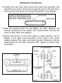
1
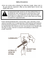
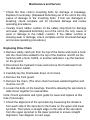
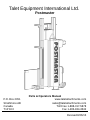
Talet Equipment International Ltd.
Postmaster
P.O. Box 2351
Strathmore AB
Canada
T1P 1K3
Parts & Operators Manual
www.taletattachments.com
[email protected]
Toll Free 1-888-317-5878
Fax 1-403-934-3042
Revised 8/26/15
To The Owner
General Comments
Congratulations on the purchase of your new Talet Postmaster. Your
unit was carefully designed and manufactured to give you many years
of dependable service. Your Postmaster will require some minor
maintenance to keep it in top working condition. Be sure to observe all
maintenance procedures and safety precautions in this manual and
the safety decals located on the unit itself and on any equipment top
which it is mounted.
About This Manual
Read this manual before using your Postmaster. This manual has
been designed to help you do a better and safer job. Read this manual
carefully and become familiar with the operating procedures before
attempting to operate. Remember, never let anyone operate this unit
without them having read a d complete understanding the “Safety
Precautions” and “Operating Instructions” section of the manual, or
having them be fully trained by an experienced, qualified person who
has read and completely understands the “Safety Precautions” and
“Operating Instructions” (see sections B and G respectively).
Service
When servicing your Postmaster remember to use only original
manufacturer replacement parts. Substitute parts may not meet the
standards required for safe, dependable operation.
To facilitate parts ordering, record the model and serial number in the
space provided on the page. This information may be obtained from
the identification plate located on the right side of the unit by the quick
attach mounting plate.
Model___________________Serial No._____________________
Your parts department needs this information to insure that you
receive the correct parts for your specific model of auger bucket.
Safety Precautions
Safety Alert Symbol
This is the “Safety Alert Symbol” used by this
industry. This symbol is used to warn of possible
injury. Be sure to read all warnings carefully. They
are included for your safety and for the safety of
others working around you.
Signal Words
Note the use of signal words Danger, Warning, and Caution with the
safety messages. The appropriate signal word for reach has been
selected using the following guidelines:
●
●
●
DANGER: Indicates an immediate hazardous situation in which, if
not avoided, will result in death or serious injury. This signal word is
to be limited to the most extreme situations; typically for machine
components which, for functional purposes, cannot be guarded.
WARNING: Indicated a potentially hazardous situation in which, if
not avoided, can result in death or serious injury and indicated
hazards that exposed when guards are removed. It may also be
used to alert against unsafe practices.
CAUTION: Indicates a potentially hazardous situation which, if not
avoided, may result in minor or moderate injury. It may also be used
to alert against unsafe practices.
Safety Rules
To insure skid steer stability, and to prevent tipping, always observe
the following safety rules:
●
●
Keep clear of unit while in operation.
Before operating the skid steer, read the operating and safety
instructions provided by the manufacturer. Observe all warnings and
caution particularly those which describe the use of seat belts and
other operator restraints and those which describe the proper way of
carrying loads as close to the ground as possible.
Safety Precautions
●
●
●
●
●
●
When using the Postmaster be sure that the proper weight of the
load is not too heavy. A light load sticking out too far can have the
same tipping effect on the loader as a heavy load carried too close.
Never operate the Postmaster when people are standing by the unit
and could be injured.
Do not obstruct your vision when traveling or working. Carry the
Postmaster low for maximum stability and visibility when traveling.
Operate at speeds slow enough so that you have complete control
at all times. Travel slowly over rough or slippery ground and on
hillsides.
Avoid steep slopes or unstable surfaces. If you must drive on a
slope, keep the load low and proceed with extreme caution. Do not
drive across a steep slope under any circumstances. Drive straight
up and down the slope.
Avoid turning on an incline, if at all possible. If it is necessary, use
extreme caution and make the turn wide and slow with the bucket
carried low.
If you can't see where you are going then stop.
Skid-steer Loader Safety
1. Read the entire skid-steer loader operators manual before ever
attempting to use the skid steer loader. This knowledge is necessary
for safe operation.
2. Follow all safety decals on the skid-steer loader. Keep them clean
and replace them if they become worn and hard to read.
3. Know the limitation of your equipment. Do not use equipment for
anything other than what it was originally designed for.
Safety Precautions
4. Pay attention to the job at hand. Do not let your mind lose
concentration on what you are doing.
5. Use your seat belt and R.O.P.S. (Roll Over Protective Structure)
when operating the skid-steer loader. Keep belt and R.O.P.S. in
good repair. Do not modify R.O.P.S. or seat belt. Do not remove
R.O.P.S. or seat belt. Overturning the skid-steer loader without
proper R.O.P.S. and seat belt can result in death.
6. Fasten your seat belt before and during skid steer loader operation.
Remain seated at all times.
7. Do not take passengers on the skid steer loader or attachment.
There is no safe place for a passenger.
8. Use hand hold when getting on and off the skid-steer loader. Failure
to do so could cause a fall.
9. Inspect the skid steer loader before you try to operate the unit.
Check for needed maintenance or repairs and have them done
before using the equipment.
10.Never leave the skid steer loader running unattended. Always lower
lift arms, set parking brake, turn off engine, and remove key.
11.Wear appropriate clothing such as safety glasses, ear plugs, etc.
Do not wear loose fitting clothing; it may catch on the equipment.
Always wear a hardhat when operating the skid-steer loader to
prevent head injury.
12.When driving on public roads use safety light, reflectors, slow
moving vehicle sign, etc., to prevent accidents. Check with local
governments for regulations that may affect you.
13.Turn off the skid-steer loader before performing maintenance. If the
lift arms must be left raised for any reason, use a positive lift arm
lock to secure arms in place. Serious damage or personal injury
could result from lift arms accidentally lowering.
14.Reduce speed when driving on rough terrain, slopes, or turning, to
avoid overturning the skid-steer loader.
Safety Precautions
15.Do not smoke when refueling the skid-steer loader. Allow room in
the gas tank for expansion. Wipe up any spilled liquid. Secure cap
tightly when done.
Escaping fluid under pressure can have efficient force to
penetrate the skin causing serious personal injury. Fluid
escaping from a very small hole can be almost invisible.
Use a piece of cardboard or wood, rather than your hands,
to search for suspected leaks.
Keep unprotected body parts, such as face, eyes, and arms, as far
away as possible from a suspected leak. Flesh injected with hydraulic
fluid may develop gangrene or other permanent disabilities. If injured
by injected fluid, see a doctor at once. If you doctor is not familiar with
this type of injury, ask him to research immediately to determine
proper treatment.
Pre-Operation
General Information
The purpose of this manual is to assist in setting up, operating and
maintaining your Postmaster. Parts lists and diagrams along with
optional equipment available are located on page of this manual. The
illustrations and data used in this manual are current at the time of
printing, however, we reserve the right to redesign and change the
Postmaster as may be necessary without notification.
Preparing the Vehicle
Your skid-steer must be equipped with a universal quick-tach hitch and
auxiliary hydraulics. Read your skid-steer loader operators manual and
know the limitations of your skid steer loader. It may require a counterweight kit to ensure that the weight of the Postmaster does not exceed
the rated capacity of your loader. Contact your local dealer if you are
mounting the Postmaster to a different skid-steer than what it was
originally purchased for and are not sure if a counterweight is required.
Never let anyone operate the skid-steer loader and
attachment without understanding all of the “Safety
Precautions” and “Operating Instructions” sections of this
manual. Always choose hard, level ground to park the skid
steer loader on and set the parking break so that the unit
cannot roll.
Additional Weight
Adding additional weight (up to 700 lbs. total hammer weight) is
recommended on both the Postmaster, except when using the T-Post
adapter. There are various options available for adding weight, for
example; logging chain, metal punch slugs, lead tire weights, etc. Do
not use concrete or sand.
Operating the hammer empty can result in vibration
causing damage to the hammer and frame. A minimum of
50 lbs. of additional weight is required before operation.
Options
Postmaster Options
The basic Postmaster is shipped complete with a 6” round post head
assembly. Refer to the table below for optional post head collars:
Option
3.5” Post Head Collar (Square)
6” Post Head Collar (Round)
8” Post Head Collar (Round)
4” x 6” H-Beam Post Head Collar (Square)
8” Post Head Collar (Square)
6” Post Head Collar (Square)
6” x 8” Post Head Collar (Square)
“T” Post Adapter*
Part #
88812
88813
88814
88815
88816
88819
89147
87122
* Requires Part #88813
Post Grapple (One Man Operation)
Allows the skid steer operator to pick up fence posts from the ground,
set them up, and pound with no extra hydraulics and is all controlled
from the cab of the skid-steer loader.
Tilt
Allows the Postmaster to hydraulically tilt left or right up to 19 degrees.
Postmaster Assembly
88 Series Postmaster
Postmaster Assembly
88 Series Postmaster
No. Req'd Part No.
1
2
1841
2
1
90295
3
1
88809
4
1
88801
1
90486
1
88802
1
90487
5
1
87592
6
1
87582
7
1
30036
8
1
30037
9
2
30038
10
1
87596
1
89143
11
6
1004
10
1004
6
87553
10
87553
6
90296
10
90296
6
90149
10
90149
12
2
87597
2
1047
2
1514
2
1536
13
4
87593
6
87593
14
8
1228
4
87563
15
1
87594
1
89142
16
4
87595
4
1513
6
87595
6
1513
Description
.50” UNC Lock Nut
Top Cover (Included in 88809)
Postmaster Hammer
Postmaster Frame - 8000 Model
Postmaster Frame with Tilt - 8000 Model
Postmaster Frame - 9000 Model
Postmaster Frame with Tilt - 9000 Model
1" Safety Catch Pin
Hair Pin 3/16" x 3 3/4"
Leveler
Leveler Guide
.25" x 1.00" Self Drilling Screw
Back Cover - 8000 & 9000 Models
Back Cover - 9000 Models Only
.25” UNC x 1.25” Hex Capscrew - 8000 Models
.25” UNC x 1.25” Hex Capscrew - 9000 Models
Rubber Retainer - 8000 Models
Rubber Retainer - 9000 Models
.25” Fender Washer - 8000 Models
.25” Fender Washer - 9000 Models
.25” UNC K-Nut - 8000 Models
.25” UNC K-Nut - 9000 Models
Rubber Cushion
.38” UNC x 2.00” Hex Capscrew
.38” Flat Washer
.38” UNC Nylock Nut
M8 x 1.25mm U-Nut - 8000 Model
M8 x 1.25mm U-Nut - 9000 Model
.50” UNC Hex Nut
.50” UNC x 3” All Thread Hex Capscrew
Front Cover - 8000 Model
Front Cover - 9000 Model
M8 x 25mm Hex Capscrew - 8000 Model
.31" Flat Washer - 8000 Model
M8 x 25mm Hex Capscrew - 9000 Model
.31" Flat Washer - 9000 Model
Postmaster Assembly
Post Head Assembly
Postmaster Assembly
Post Head Assembly
No. Req'd Part No.
1
2
1841
2
4
1646
3
8
87553
4
2
87588
5
1
88810
6
2
88811
7
1
----88812
88813
88814
88815
88816
88819
89147
87122
8
2
10002
Description
.50” UNC Lock Nut
.50” Heavy Washer
Rubber Retainer
Upper Guide Block
Post Upper Head Plate
Intermediate Guide Block
Post Head Collar
3.5” Post Head (Square)
6” Post Head (Round)
8” Post Head (Round)
4” x 6” H-Beam Post Head (Square)
8” Post Head (Square)
6” Post Head (Square)
6” x 8” Post Head (Square)
“T” Post Adapter*
.50” UNC x 7” Hex Capscrew GR8
The following upper head and collar assemblies include all parts
needed to update units that have a four-bolt collar pattern to the new
design:
●
3.5” Post Head Collar (Square) and Upper Head Plate Assembly – 88803
●
6” Post Head Collar (Square) and Upper Head Plate Assembly – 90076
●
6” Post Head Collar (Round) and Upper Head Plate Assembly – 88804
●
8" Post Head Collar (Round) and Upper Head Plate Assembly – 88805
Postmaster Assembly
Drive Assembly
Postmaster Assembly
Drive Assembly
No. Req'd Part No.
1
2
87541
2
2
87542
3
1
87543
1
87544
4
2
87598
5
4
87545
6
8
87564
7
1
87546
1
87216
8
1
87547
9
1
87549
10
1
87548
11
1
87540
1
87551
12
2
1092
2
90005
2
1841
13
1
87608
14
1
87599
15
1
87600
16
8
87601
17
16
2653
16
87565
18
1
87508
19
6
1004
20
1
90526
Description
Bushing (Includes (3) Capscrews and (1) Key)
Double Tooth Sprocket
Drive Chain – 8000 Series
Drive Chain – 9000 Series
Replacement Key
Bearing Assembly
.31” UNC x 1.25” Flathead Socket Capscrew
Nylong Guide Plate – 8000 Series
Nylong Guide Plate – 9000 Series
Chain Coupler (1.25” - Drive Chain Side)
Chain
Chain Coupler (1.00” - Hydraulic Motor Side)
Hydraulic Motor 101-1036
Replacement Key
.50” UNC x 2.00” Hex Capscrew
.50" Flat Washer GR8
.50” UNC Lock Nut
Replacement Key
Drive Shaft
Idler Shaft
.31” UNC K-Nut
M10 x 35mm Hex Capscrew
M10 Hex Nut
Motor Spacer
.25" x 1.25" Hex Capscrew
Bearing Spacer
Postmaster Assembly
Hydraulics
Postmaster Assembly
Hydraulics
No. Req'd Part No. Description
1
1
90198 Hose Assembly .50” x 30” 8FJ – 8FJ
2
1
87538 Hose Assembly .50” x 24” 8FJ – 8FJ
3
1
90038 Tee 8 MB - 8 MJ – 8MJ
4
1
90158 Flow Control Valve
2
90450 .25" UNC x 2.50" Hex Capscrew
2
1842 .25" UNC Lock Nut
5
1
90040 90° Elbow 8MB – 8MJ
6
2
90199 Hose Assembly .50” x 80” 8FJ – 10MB
7
2
3070 Straight Adapter 10MB – 8MJ
8
1
87540 Hydraulic Motor 101-1036
9
1
80132 Flat Face Female Coupler (10 ORB)
10
1
80133 Flat Face Male Coupler (10 ORB)
11
1
90039 Straight Adapter 8MB – 8MJ
Postmaster Assembly
Optional Post Grapple Assembly
Postmaster Assembly
Optional Post Grapple Assembly
No.
1
2
3
4
5
6
7
8
9
10
11
12
13
14
15
16
17
18
19
20
21
22
23
24
25
26
27
28
29
30
Req'd Part No.
2
1839
2
1517
1
87527
2
87528
2
87529
2
87530
2
3171
1
87531
1
87532
1
61464
1
61465
1
87576
1
87577
1
87533
4
87578
1
87579
1
87534
1
87535
1
1112
1
1506
1
1517
1
1936
1
1149
2
90074
2
87582
2
90223
1
87583
1
87584
1
87585
2
90073
1
1745
1
87587
1
88326
Description
.62” UNC Lock Nut
.62” Flat Washer
Chain Guard
Spanner Bushing
Idler Sprocket Bushing **Discontinued**
Idler Sprocket
90° Elbow 4MB - 4MJ
Hose Assembly .25” x 60” 4FJ – 4MP
Hose Assembly .25” x 68” 4FJ – 4MP
Female Coupler
Male Coupler
Cylinder
Grapple Chain (With Spring Link)
Grapple Chain
Connector Link
Pivot Actuator
Actuator Shim
Spring - 5/8” x 8 ½”
.62” UNC x 1.00” Hex Capscrew
.62” Lock Washer
.62” Flat Washer
.75” UNC Lock Nut
.75” UNC x 5.00” Hex Capscrew
.75" Nylon Bushing
Hair Pin
Hitch Pin (Includes Hair Pin)
Grapple Pivot Mount
Pivot Actuator (Includes Nuts and Zerks)
Actuator Pivot Plate
1" Nylon Bushing
.44” UNC Nylock Nut
Chain Anchor (.44” UNC)
Grapple Frame
Postmaster Assembly
Hydraulics - Postmaster With Grapple
Postmaster Assembly
Hydraulics - Postmaster With Grapple
No. Req'd Part No.
1
1
90198
2
1
87538
3
1
90038
4
1
90158
2
90450
2
1842
5
1
90040
6
2
90199
7
2
3070
8
1
87540
9
1
80132
10
1
80133
11
1
90039
12
1
90159
13
1
90155
14
1
90240
15
1
90239
16
2
90241
17
2
90242
18
1
30183
19
1
61464
20
1
61465
Description
Hose Assembly .50” x 30” 8FJ – 8FJ
Hose Assembly .50” x 24” 8FJ – 8FJ
Tee 8 MB - 8 MJ – 8MJ
Flow Control Valve
.25" UNC x 2.50" Hex Capscrew
.25" UNC Lock Nut
90° Elbow 8MB – 8MJ
Hose Assembly .50” x 80” 8FJ – 10MB
Straight Adapter 10MB – 8MJ
Hydraulic Motor 101-1036
Flat Face Female Coupler (10 ORB)
Flat Face Male Coupler (10 ORB)
Straight Adapter 8MB – 8MJ
Tee 8MJ – 8MJ – 8FJ
Tee 8MJ – 8MJ – 8MB
Straight Adapter 8MB - 8FJ
Check Valve - 8FB
Reducer 8FJ - 4MJ
90° Elbow 4MP - 4FJ
Swivel Adapter with Restrictor
Female Coupler
Male Coupler
Postmaster Assembly
Postmaster With Tilt Assembly
Postmaster Assembly
Postmaster With Tilt Assembly
No. Req'd Part No.
1
1
90297
2
1
3
2
90298
4
1
90282
2
90451
5
2
90276
6
1
90278
7
1
90277
8
1
90492
90491
9
1
90493
90491
10
1
90281
11
1
90299
12
1
1003
1
90300
13
1
90292
14
1
30183
15
1
90291
16
10
1090
17
10
90301
18
3
6616
19
1
89289
Description
Mount Plate
Postmaster Frame*
Guide Plate
Diverter Valve
.31" UNC x 3" Socket Head Capscrew
Straight Adapter 10MB - 4MJ
Hose Assembly .25" x 32" 4FJ - 90° 4FJ
Hose Assembly .25" x 39.75" 4MP - 90° 4FJ
Hose Assembly .50" x 22.5" 10MB - 8FJ
Hose Assembly .50" x 20.5" 10MB - 8FJ**
Hose Assembly .50" x 26.5" 10MB - 8FJ
Hose Assembly .50 x 20.5" 10MB - 8FJ**
Cylinder
Cylinder Pin
.25" UNC x 1.00" Hex Capscrew
.25" UNC Centrelock Nut
90° Elbow 6MB - 4FP
Swivel Adapter with Restrictor
90° Elbow 6MB - 4MJ
.50" UNC x 1.50" Hex Capscrew
.50" UNC Centrelock Nut
.25" Grease Zerk
Wire & Plug Assembly
* Top of frame has been removed for better visibility.
** Used with post grapple option.
Postmaster Assembly
Postmaster With Tilt Wiring
Magnetic Switch Box
Part No. Description
15756
Electrical Control - Battery
In-Cab Controls
Part No. Description
25887
Electrical Control - 14 Pin Case/New Holland/Volvo/Ditch
Witch/Kubota
25904
Electrical Control - 14 Pin John Deere
25886
Electrical Control - 8 Pin ASV/CAT/Komatsu
Mounting Instructions
After determining the right capacity of your loader and adding any
counterweight kits that are needed you are ready to install your
Postmaster.
Installation Instructions
1. If you unit was shipped in the upright position, remove the lag bolt
that is bolting the Postmaster to the pallet.
2. Remove the metal bands from around the mounting plate and pallet.
3. If you have received a Postmaster with Grapple, remove the grapple
assembly from the top of the Postmaster. The grapple will be
installed later.
4. Attach the Postmaster to your skid steer by following your skid-steer
operators manual for installing an attachment. After making sure the
attachment is securely latched to the skid-steer, remove the
shipping pallet.
5. Remove the hydraulic hoses from the “D” ring hose guide and
connect to your skid-steers auxiliary hydraulics.
6. Remove the transit bolt from the top left of the hammer rails and
install in the storage hole located on the left side of the unit.
Do not route hydraulic hoses through the “D” ring hose
guide on the quick-tach mounting plate at this time.
Damage to the hydraulic hoses will occur.
Mounting Instructions
Do not operate with the transit bolt installed and do not
transport without re-installing the transit bolt.
7. Raise the Postmaster in the air and tilt forward 90°. Watch for any
obstructions or pinching of hydraulic hoses.
Do not tilt the Postmaster with holes in the “D” ring hose
guide. Damage to the hoses will occur.
8. Grease the exposed hammer rails as well as the upper and lower
bearing assemblies. If the post pounder includes the optional tilt
feature, also grease the cylinder and the main mounting plate using
the two grease zerks located on the front side.
9. After ensuring that the safety catch is in place, pull the hammer out
towards you until it hits it's safety catch. The chain drive unit can
now be run without effecting the hammer, therefore allowing you to
set the flow control.
10.Grease the rest of the hammer rails and oil the chain drive.
Do not operate the Postmaster without first setting the flow
control. Serious damage to the drive assembly may occur.
11.Before starting the skid-steer, set the flow control at three (3).
12.With the skid-steer running at full throttle, engage the auxiliary
hydraulics. Note the direction of the chain rotation (this is visible
from the operator's seat). The chain should be rotating from the
bottom to the top. If it is not, reverse the hydraulic hoses at the skidsteer end.
Mounting Instructions
Note: On Postmasters with grapples, if the chain is not running at all,
reverse the hoses.
13.After the correct chain rotation has been achieved, count the
number of rotations of the pick up link per minute. This is visible
from the operators seat or looking down at the chain.
14.Time the number of rotations and increase the flow control setting
by one (1) increment at a time until you reach the desired number of
rotations per minute but DO NOT exceed the maximum of 50
rotations per minute for safe performance.
Keep hands and loose clothing clear of the chain drive
assembly. Severe personal injury could occur.
15. When the flow control has been properly set, turn off the auxiliary
hydraulics and slide the hammer back into the Postmaster until it
reaches the bottom.
Exceeding 50 rotations per minute will cycle the chain
faster than the hammer drops making the chain come into
contact with the hammer as it is still falling causing severe
damage to the drive assembly.
16.Slowly tilt the Postmaster back to a vertical position.
Mounting Instructions
17. Shut off the skid-steer and disconnect the hydraulic hoses. Route
the hoses through the “D” ring hose guide on the quick-tach mounting
plate and reconnect to the skid-steer auxiliary hydraulics.
18. Your Postmaster is ready for operation.
Note: If you have purchased a Postmaster with the Post Grapple
Assembly it is recommended that you use your Postmaster without the
grapple a few times before installing. Therefore the Post Grapple
Installation Instructions are located in the operating section of this
manual following the Postmaster Operation Instructions.
Operating Instructions
General Information
After reading all “Safety Precaution” and following the “Mounting
Instructions” in this manual you are ready to operate your Postmaster.
In this section you will find operating instructions for the Postmaster
and Postmaster with Grapple.
Postmaster Operation
If you have purchased a Postmaster with Post Grapple Assembly, we
recommend that you use your Postmaster without the grapple a few
times before installing.
1. The basic Postmaster requires a second person to position the
fence post. This person will set the fence post at the desired location
and grasp the post securely making sure his hands are at least 30”
from the top of the post.
2. After the post is in position the skid-steer operator can move the
skid-steer into position with the arms raised and the Postmaster
positioned directly over the top of the fence post.
3. Lower the Postmaster onto the top of the fence post (ensuring that
the post is inside of the positioning collar) keep lowering until the
collar and head assembly has moved up approximately 2 inches.
This can be measured by watching the post guide on the back of the
unit which is visible from the skid-steer operators seat.
Operating Instructions
4. After the second person has cleared the area, continue lowering the
Postmaster onto the post approximately 24 inches. This can be
measured by noting when the post guide is approximately 6 inches
above the first reinforcement plate.
5. The Postmaster can now be activated by turning the auxiliary
hydraulics to the forward or locking position. Drive the post into the
ground until the post guide is approximately 6 inches above the
rubber cushion on the safety stop block. Shut off the auxiliary
hydraulics and reposition the skid-steer to ensure that the post is
driven into the ground STRAIGHT.
6. Repeat steps 4 & 5 until the post has been driven to the desired
depth.
7. Shut off the auxiliary hydraulics and raise the Postmaster until the
post is cleared and move onto the next post.
Operating Instructions
Postmaster with Grapple Installation
Once you have become comfortable with the operation of the
Postmaster and are driving the posts in straight, you are ready to
install your Post Grapple Assembly.
1. Lower the Postmaster to the ground and shut off the skid-steer
loader.
2. Set the grapple unit down in front of the Postmaster aligning the
square tubes of the grapple with the square tubes of the Postmaster.
(One on either side of the chain guard and drive assembly.)
3. Remove the hitch pins from the post grapple mounting plates.
4. Slide the square tubes of the grapple into the tubes of the
Postmaster. Align the mounting holes and insert the hitch pins and
spring pins provided.
5. Route the hydraulic hoses for the post grapple through the “D” ring
hose guide and connect to the corresponding connectors located
directly below the flow control.
6. The hydraulic system has been shipped dry and will require that the
auxiliary hydraulics be activated slowly to fill the hoses, motor and
cylinder. (The post grapple may act erratic until all the air is out of
the hydraulic system.)
7. With the skid-steer running at slow idle, turn the auxiliary hydraulics
to the forward locking position for a few seconds at a time until the
grapple arms raise. (Be cautious when the grapple is raised and the
jaws are completely open as the post hammer will raise.)
8. Reverse the auxiliary hydraulics until the jaws close.
9. Repeat steps #7 & #8 until grapple operation is smooth.
10.Once you have accomplished smooth operation and the grapple
jaws are closed, return the auxiliary hoses to the forward or locking
position until the hammer starts to raise. This will raise and open the
grapple jaws.
11.The Postmaster and Post Grapple are now ready for operation.
Operating Instructions
Postmaster with Grapple Operation
Picking up a post from the ground may require a few tries to get it
perfect. We recommend attaching a 24” length of deck chain to the
hook provided next to the bottom of the drive assembly. This will help
the operator align the grapple jaws with the head of the fence post,
ensuring a perfect pick-up of the fence post every time.
NOTE: This guide chain may need to be adjusted up or down in length
to compensate for the arc of the skid-steer's lift arms.
1. Set a fence post on the ground with the head of the post facing the
skid-steer.
2. Raise the Postmaster approximately two feet off the ground (making
sure that the grapple arms are in the UP position and the jaws open.
Refer to step 10 in the Post Grapple Installation Instructions.
3. Drive forward and position the Postmaster over the head of the
fence post. Align the end of the guide chain approximately 1” to 2” to
the right of the head of the fence post. NOTE: You do not need to
center the jaws over the post since the grapple is self aligning.
4. After the skid-steer is in position, lower the lift arms until the
Postmaster is resting lightly on the fence post, allowing for the
grapple to center the post.
5. Turn the auxiliary hydraulics to the reverse position until the jaws
close on the fence post.
6. Lift the Postmaster 4” to 6” off the ground and repeat step 5.
7. Raise the arms of the skid-steer until the fence post has swung
down and is clear of the ground. This should set the head of the
fence post into the positioning collar. If the fence post is jammed
against the front or back of the positioning collar DO NOT release
Opening the jaws of the grapple when the fence post is not
in the positioning collar could cause the post to fall back
toward the skid-steer. Serious injury to the operator could
occur.
Operating Instructions
the jaws. Back up the loader while lowering the fence post to the
ground. Once the post is on the ground, open the jaws.
NOTE: If the fence post was jammed on the back side of the
positioning collar (towards the skid-steer), shorten the guide chain one
link at a time (repeat steps 3-7) until the fence post is positioned in the
collar. If the fence post was jammed on the front of the positioning
collar, lengthen the guide chain one link at a time (repeat steps 3-7)
until the fence post is positioned in the collar.
8. When the fence post has been properly positioned in the positioning
collar, move the skid-steer to the desired location and lower the lift
arms until the tip of the post is touching the ground.
9. Briefly turn the auxiliary hydraulics to the forward position (just
enough to release the hydraulic pressure). You do not want the jaws
to open at this time. Releasing the hydraulic pressure should loosen
the jaws enough that the post will slide through but still maintain the
spring tension that is holding the post in position.
10.Align the fence post by moving the skid-steer and using the guide
chain as a plum line.
11.Lower the Postmaster onto the fence post approximately 24 inches.
Reposition the skid-steer using the guide chain as a plum line.
12.Turn on the auxiliary hydraulics in the forward position which will
open the jaws, swing the grapple assembly up out of the way and
start the hammer.
13.Continue pounding the post into the ground until the post guide /
hammer stop is approximately six (6) inches above the rubber
cushion on the safety stop block. Turn off the hydraulics and
reposition the lift arms.
14.Repeat steps 11-13 until the post is driven to the desired depth.
Operating Instructions
Failure to lower the Postmaster as the post guide nears
the rubber cushion on the safety stop block will result in
the hammer bottoming out. Although occasionally bottom
out the hammer will give the operator a jolt it will not under
normal load conditions damage the Postmaster. However,
repeated bottoming out of the hammer will cause structural
damage and excessive wear to the Postmaster and skidsteer lift arms.
15. Turn off the auxiliary hydraulics and raise the Postmaster up off the
post and proceed to the next post.
Postmaster With Tilt Operation
1. Grease the cylinder as well as the front mounting plate using the
two grease zerks provided.
2. Attach the wiring harness to the Diverter valve on the Postmaster.
Run the wires along the hoses to the skid-steer using zip-ties to
secure them as you go along.
3. Run the control portion of the wiring harness up the arm of your
skid-steer and into the cab keeping the wiring away from hot
components such as a heater or exhaust. Mount the switch out of the
way of other controls.
4. The remainder of the wiring harness needs to be hooked up to a 12
volt power supply. Consult your dealer with assistance if needed.
5. Move the skid-steer to an area with no obstacles blocking the
postmaster operation.
6. Hold the switch in either direction while enabling the auxiliary
hydraulics to tilt the Postmaster.
Maintenance and Service
General Information
Your Postmaster was designed to be virtually maintenance free. Very
little effort is needed to keep it in top condition. It is however, important
to follow these procedures to get full performance and longevity out of
the unit.
Perform maintenance only when the Postmaster has been
completely lowered to the ground and hydraulically
disconnected from the skid-steer.
Lubrication
Every 40 Hours
●
●
Grease the zerks on each of the four (4) bearings
Grease zerks on both ends of the pivot linkage on the post grapple
assembly.
●
Grease zerks on each side of the tilt plate.
●
Lubricate hammer rails
●
●
●
Lubricate drive chain and chain coupling with a high quality
commercial chain lubricant.
Visually inspect the nylon guide plate for wear. Replace if the drive
chain is hitting the flathead socket capscrews.
Check the bolts on the Postmaster upper head assembly for
tightness.
Daily Inspection
• Check hydraulic hoses for damage, leakage or signs of excessive
heat. Replace is necessary.
• Check all bolts for tightness.
• Visually inspect the machine for damage.
• Visually check the drive chain for alignment.
Maintenance and Service
●
●
Check the flow control mounting bolts for damage or breakage.
Replace if necessary. (Repeated bottoming out of the unit is the only
cause of damage to the mounting bolts. If bolt are damaged or
breaking, check complete unit for structural damage and review
operating procedures.
Visually check rubber cushion on the safety stop block for damage
and wear. (Repeated bottoming out of the unit is the only cause of
wear or damage to the rubber cushion. If the rubber cushion is
showing wear or damage, check complete unit for structural damage
and review operating procedures.)
Replacing Drive Chain
1. Remove safety catch pin from the top of the frame and insert a hook
into the chain links welded to the top of the hammer and lift out the
hammer with a hoist, forklift, or another skid-steer. Lay the hammer
on the ground.
2. Disconnect the hydraulic hoses and remove the Postmaster from
the skid-steer loader.
3. Carefully lay the Postmaster down on it's back.
4. Remove the front guard.
5. Remove the chain. (The drive chain has been welded together and
must be cut off.
6. Loosen the bolts on the bearings, therefore allowing the sprockets to
slide closer together for reassemble.
Note: Check sprockets and nylon guide for wear and replace at this
time if necessary.
7. Check the alignment of the sprockets by measuring the distance
from each side of the sprocket to the frame on the upper and lower
sprocket. Then place a straight edge on the side of the sprockets
from the upper sprocket to the lower sprocket to ensure straight
alignment. See diagram on next page.
Maintenance and Service
8. Position the new drive chain around the frame and sprockets and
install the pick-up link. Drive pins through the pick-up link and chain,
weld connector pin holes shut and grind weld flush. See diagram
9. Slide the bearings back out and tighten the bolts. Measure the
distance between the two shafts. This measurement must be the
same on both sides. See diagram.
10.Check the tension of the drive chain by either placing a 50 lb.
Weight or the upper head assembly on the center of the chain,
midway between the upper and lower sprocket. Deflection with the
weight placed on the chain should be 3/16”. Tighten or loosen chain
as needed.
Maintenance and Service
Removal
To remove the Postmaster, just follow the simple procedure outlined
below. Remember, always position the skid-steer loader on hard and
lever ground when the unit is to be removed.
1. Lower the Postmaster to the ground.
2. Unlock the toolbar attachments locking levers.
3. Slowly tilt the toolbar forward while driving in reverse to clear the
unit without going so far as to stress the hydraulic lines.
4. Shut off the engine and set the parking brake. Relieve the hydraulic
pressure from the hoses.
5. Climb out of the skid-steer. Disconnect the hydraulic hoses from the
skid-steer's auxiliary hydraulics. Connect the power and return hose
couplers together to keep foreign particles out of the hydraulic
system.
Storage
To prepare the Postmaster for storage, first wash off all dirt and grime
from the unit. If you have a post grapple or the tilt option, coat the
exposed portions of the cylinder rod with grease. Lubricate the drive
chain and chain coupler and all grease fittings. Make sure the
hydraulic system is properly sealed against contaminates entering the
unit. When storing the Postmaster, place the unit somewhere clean
and dry with a cover over it if possible.
Specifications
DESCRIPTION
Overall Length
Overall Width
Overall Height
8000 SERIES POSTMASTER SPECIFICATIONS
8000 SERIES
48” (121cm)
24” (61cm)
64” (163cm)
Hammer Weight
Length of Stroke
Strokes Per Minute
Motor
Minimum Hydraulic Requirements
Skid-Steer Mounting
Posts (Wood/Steel)
DESCRIPTION
Overall Length
Overall Width
Overall Height
275 LBS (125kg)
36” (91cm)
50
Eaton
12 GPM (45 LPM)
2600 PSI (136 BAR)
Universal Hitch
3” - 8” (8-20cm)
Optional T-Post and H-Beam Adapter
9000 SERIES POSTMASTER SPECIFICATIONS
9000 SERIES
48” (121cm)
24” (61cm)
90” (229cm)
Hammer Weight
Length of Stroke
Strokes Per Minute
Motor
Minimum Hydraulic Requirements
Skid-Steer Mounting
Posts (Wood/Steel)
275 LBS (125kg)
56” (142cm)
50
Eaton
12 GPM (45 LPM)
2600 PSI (136 BAR)
Universal Hitch
3” - 8” (8-20cm)
Optional T-Post and H-Beam Adapter
All specifications and designs are subject to change without notice and without liability
therefore.
Decals
The diagrams on this page show the location of all the decals used on
the Talet Postmaster and/or Slab Blaster. The decals are identified by
their part number, with reductions of the actual decals located on the
following pages. Be sure to read all decals before operating the
Postmaster and/or Slab Blaster. They contain information you need to
know for both safety and machine longevity.
Warranty
All new Talet products are warranted to be free from defects in
materials or workmanship which may cause failure under normal
usage and service when used for the purpose intended.
In the event of failure within twelve (12) months from initial retail sale,
lease or rental date (excluding cable, ground engaging parts such as
sprockets, digging chain, bearings, teeth, tamping and demolition
heads, blade cutting edges, pilot bits, auger teeth, auger heads &
broom bristles), if after examination, Talet determines failure was due
to defective material and/or workmanship, parts will be repaired or
replaced. Talet may request defective part or parts be returned prepaid
to them for inspection at their place of business at Strathmore, Alberta
or to a location specified by Talet.
Any claims under this warranty must be made within fifteen (15) days
after the Buyer learns of the facts upon which such claim is based. All
claims not made in writing and received by Talet within the time period
specified above shall be deemed waived.
This warranty is in lieu of all other warranties expressed or implied and
there are no warranties of merchantability or of fitness for a particular
purpose. In no event shall talet be liable for consequential or special
damage.
Talet's liability for any and all losses and damages to buyer, resulting
from any cause whatsoever, including talet's negligence, irrespective
of whether such defects are discoverable or latent, shall in no event
exceed the purchase price of the particular products with respect to
which losses or damages are claimed, or, at the election of talet, the
repair or replacement of defective or damaged products.