1
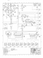
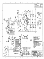
SR-6520 / SR-8520 /P / PD POWERED MIXERS w/ DIGITAL EFFECTS SR-6520P/PD SR-8520P/PD SR-6520P p/n 071-6521-100 (120V) SR-8520P p/n 071-8521-100 (120V) SR-6520PD p/n 071-6521-200 (120V) SR-8520PD p/n 071-8521-200 (120V) (These are the model names for warranty claims) SERVICE MANUAL MARCH 1998 IMPORTANT NOTICE: The information contained herein is CONFIDENTIAL and PROPRIETARY to Fender Musical Instruments Corp. It is disclosed solely for use by qualified technicians for purposes of equipment maintenance and service. It is not to be disclosed to others without the expressed permission of Fender Musical Instruments Co. All specifications subject to change without notice. CONTENTS: For warranty repair service, only Fender specified part numbers are to be used. It is recommended they also be used for post-warranty maintenance and repair. Notices Specifications Circuit description Parts lists: Preamp PCB assy Front panel assy Pwr amp PCB assy Rear panel assy Cabinet assembly Miscellaneous Dig rev cntrl Schematics Service diagram Parts marked with an asterisk (*) indicate the required use of that specific part. This is necessary for RELIABILITY and SAFETY requirements. DO NOT USE A SUBSTITUTE! A coded naming convention is used in the description of certain parts. The codes and what they mean are as follows: CAPACITOR CODES HARDWARE CODES CAP AE CAP CA CAP CD CAP MPF CAP MY CAP PFF BLX CR HWH M NI OHP PB PHP PHPS SMA SMB SS TF ZI = = = = = = Aluminum Electrolytic Ceramic Axial Ceramic Disk Metalized Polyester Film Mylar Polyester Film/Foil RESISTOR CODES RES CC RES CF RES FP RES MF RES WW Fender Musical Instruments Corp. 7975 North Hayden Road Scottsdale, AZ 85258 1 = = = = = Carbon Comp Carbon Film Flame Proof Metal Film Wire Wound = = = = = = = = = = = = = = Black Oxide Chrome Plated Hex Washer Head Machine Screw Nickel Plated Oval Head Phillips Particle Board Pan Head Phillips Pan Head Phillips Sems Sheet Metal "A" Point Sheet Metal "B" Point Stainless Steel Thread Forming Zinc Plated CIRCUIT DESCRIPTION SPECIFICATIONS Type: PR 189 POWER AMPLIFIER: The signal from the preamp feeds from P1B pin 4, through a ribbon cable, to P1A on the power amplifier PCB. The signal couples (via C1) to the unity gain amplifier U1B. U1B contains a closed loop (gain of 1) negative feedback path, along with positive feedback through the inverting Operational Transconductance Amplifier (OTA) U2. U1B and U2 make up the gain reduction circuit for the DELTACOMP clip protection feature. POWER AMPLIFIER SECTION: Power output: 520 Watts R.M.S. @ 2 Ohms 350 Watts R.M.S. @ 4 Ohms Distortion at 520 watts: Less than .2% @ 1 kHz into 2 Ohms Minimum load impedance: 2 Ohms Sensitivity: 1.28V R.M.S. Input impedance: 22K ohm DELTACOMP range: The attack and release circuit for the DELTACOMP is made up by the Diode, Resistor, and Capacitor network which drives the Base of Q29. Comparator U1A senses the voltage from the Collectors of Q27 & Q28. When the power amplifier approaches clipping on a positive swing, the collector of Q9 pulls up R50, which turns on Q28, transferring 15vdc to the collector, pulling down R52. This causes the output (pin 1) of U1A to switch from +15vdc to -15vdc, lighting the DELTACOMP/Clip Led. Note when the DELTACOMP is disabled, the Led indicates clipping of the output stage. With the DELTACOMP enabled, the Led indicates an active DELTACOMP circuit. The negative control voltage from R52 also feeds through P1A to P1B on the preamp PCB. The voltage is routed to the DELTACOMP switch (S1), located on the front panel. With the switch engaged, the control voltage is sent back through the ribbon cable (via P1 pin 6) to the attack/release circuit. The negative voltage drives through Diodes CR34 - CR37, and charges Capacitors C26-C29 all at once in parallel as a one pole filter through a single time constant of R52 X (C26+27+28+29) or 3.9K X 8.8µF = 34.3ms. As they charge, Q29 turns on and provides current to pin 5 of the OTA (U2). The current controls the output amplitude of U2. The inverted signal from U2 mixes with the input to U1B providing cancellation which reduces the input to the power amplifier. This prevents the amplifier from clipping. When the output of the power amplifier is reduced, the output of U1A toggles back to +15vdc. Due to the blocking action of Diodes CR34 - CR37, Capacitors C26-C29 are forced to discharge as a 4-pole filter with different time constants through R58. R62 prevents Parasitic oscillation while Zener CR38 provides 2 slopes which results in smoother limiting. 20 dB PREAMP SECTION: Input impedance: LOW-Z HI-Z Hi-Z Input Sensitivity for 520 watts: 55 mV (MAIN MASTER and CHANNEL Main at maximum,all tone controls and GEQ at "0" detent). Channel tone controls: Graphic equalizer: 1.82k 18.2k When the power amplifier approaches clipping on a negative swing, R46 is pulled low, turning on Q26 which pulls up the Base of Q27 transferring -15 vdc to the collector. JFET Q1 and associated components provide a 4-5 second turn-on delay for the audio input to the power amplifier. When the power is switched on, Capacitor C3 charges through Resistor R4. The negative Gate voltage pinches off the JFET, removing the ground from the input of the amplifier. When the power is switched off, C3 immediately discharges through Diode CR1, grounding the input of the amplifier. LOW +/- 15 dB at 100 Hz MID +/- 15 dB at 750 Hz HIGH +/- 15 dB at 10 kHz TROUBLESHOOTING TIP: Check for proper operation of this circuit when experiencing excessive turn-on or turn off "Pops", or no output when signal applied to the input. Many times the JFET itself can be the culprit. NOTE: Excessive turn-off "Pops" can also be caused by uneven discharge of the +/- power supplies. Usually a mismatch in the Filter Capacitors will cause this problem. Its easy to look at both supplies on an oscilloscope. Invert one scope input and check for even discharge to zero volts. +/- 12 dB at 63, 125, 250, 500, 1k, 2k, 4k, 8k, and 16kHz. Dimensions: Height: Width: Depth: Weight: SR 6520PD 10-7/16 inches (26.5 cm) 23-5/8 inches (60.0 cm) 12 inches (30.5 cm) 40.0 lbs. (18.2 kg) Q4 is the current source for the Differential Amplifier (Q2, Q3). For the Diff amp to work properly, one half of the current from the current source must flow through each leg of the Diff amp. If the same amount of current flows through each leg of the Diff amp, the voltage drop across resistors R12 & R13 must be the same. If not, there will be a DC offset at the output of the amplifier. The overall gain of the amplifier is set up around the Diff amp. R15 (27K) is the feedback resistor and R14 (1K) is the pull-down resistor. Rfb + Rpd ÷ Rpd = Av. Therefore 27K + 1K ÷ 1K = 28K ÷ 1K = 28 Av. SR 8520PD 10-7/16 inches (26.5 cm) 27-5/8 inches (70.2 cm) 12 inches (30.5 cm) 42 lbs. (19.1 kg) 2 CIRCUIT DESCRIPTION Cont. PARTS LIST NOTE: SHADED ITEMS ARE FOR REFERENCE ONLY Q7 & Q11 make up a voltage amplification stage. Again, to operate properly, the same amount of current must flow through these transistors. Thus the voltage drop across R21 & R22 must be the same. NOTICE: Reference designators 100-199 refer to and are listed only for channel 1. Channel 2 designators are 200-299 etc. Part quantities are listed only for the SR-6520PD (6 channel version). Adjustable bias is provided by Q8 & it's associated components. 1.2volts is provided to the Base of Driver Transistors Q14 & Q15, and -1.2 volts is provided to the base of the Driver Transistors. This provides + or - 0.6 volts to the bases of the output transistors (Q18-Q25) in parallel, biasing them on. PREAMP PRINTED CIRCUIT BOARD ASSEMBLY Transistors Q12, Q13, and associated components comprise the Current Limiting or Short Proof protection circuit. There are usually two conditions which demand excessive output current from the amplifier. A shorted speaker cable, or a load impedance which is below the minimum rating of the amplifier. If these conditions occur, the voltage drop across the Emitter Resistors (.33Ω 5 Watt) will dramatically increase. On the positive side of the amplifier, C11 charges through R25 & R27. On the negative side C12 charges through R31 & R32. This will cause Q12 & Q13 to turn on. This limits the amount of signal which is available to the Base of the Driver Transistors (Q14 - Q17). QTY DIFFERENCES IN VERSIONS: In all versions (SR6520/8520, SR6520P/8520P, & SR6520PD/8520PD) the power amp remained unchanged; normal schematic revisions were not related to version changes. The "P" version added Phantom power, which caused the preamp PCB assy to change by adding traces to carry phantom power to the XLR microphone connectors, and added a +15V regulator circuit to the preamp PCB assy in order to provide the phantom power. The "PD" version added digital effects (PCB assy 041875) and a ribbon cable to connect the PCB's together (P2 to P3), along with some obvious cosmetic changes WARRANTY PHILOSOPHY ON DIGITAL REVERB MODULE: Replacement, rather than repair of the 041092 module is the recommended warranty procedure for failures of the module. 3 DESCRIPTION REFERENCE DESIGNATION 1 1 1 1 PART # 037832 037875 049148 049271 PCB. ASSY PREAMP SR6520P PCB. ASSY PREAMP SR8520P PCB ASSY PREAMP SR6520PD PCB ASSY PREAMP SR8520PD (STUFFED) (STUFFED) (STUFFED) (STUFFED) 1 1 1 028577 038534 048914 CABLE ASSY REVERB 30" CABLE, JUMPER 3CKT RIBBON CABLE, RIBBON 8CKT RIBBON (SR6520/8520/P) P2 TO P3 (SR6520/8520/P TAPE IN) 1 1 21 1 1 1 1 17 13 028485 028492 028465 028474 033605 037943 033606 028459 028460 CAP AE RDL CAP AE RDL CAP AE RDL CAP AE RDL CAP AE RDL CAP AE RDL CAP AE RDL CAP AE RDL CAP AE RDL C11 C10 C14,16,25,103,104,111 C7 C29 C37 C27 C3,12,18-20,105,106 C5,114,115 20 12 12 1 6 1 1 020909 069724 025984 007029 025986 025777 020842 CAP CD CAP CD CAP CD CAP CD CAP CD CAP CD CAP CD 1 2 1 1 1 16 1 1 2 033588 033578 036234 033590 033591 033596 033579 033580 033581 CAP PF RDL 100V .01uF 10% CAP PF RDL 100V .001uF 10% CAP PF RDL 100V .015uF 10% CAP PF RDL 100V .022uF 10% CAP PF RDL 100V .033uF 10% CAP PF RDL 100V .068uF 10% CAP PF RDL 100V .0015uF 10% CAP PF RDL 100V .0022uF 10% CAP PF RDL 100V .0033uF 10% 16V 16V 25V 25V 50V 50V 50V 50V 50V 1KV 1KV 1KV 1KV 1KV 1KV 1KV 470uF 20% 1000uF 20% 22uF 20% 100uF 20% .15uF 20% .33uF 10% .47uF 20% 2.2uF 20% 4.7uF 20% 47pF 10% 100pF 10% 180pF 10% 220pF 10% 390pF 10% 470pF 10% 500pF 10% @ P1 (SR6520/8520PD) C4,6,13,15,21-24,112,113 C101,102 C107,108 C34 C110 C42 C9 C36 C32,40 C41 C26 C31 C1,2,8,39,116,117 C30 C35 C17,38 PARTS LIST PARTS LIST PREAMP PRINTED CIRCUIT BOARD ASSEMBLY (CONT) QTY DESCRIPTION REFERENCE DESIGNATION 1 1 7 PART # 033582 033583 033586 CAP PF RDL 100V .0039uF 10% CAP PF RDL 100V .0047uF 10% CAP PF RDL 100V .0068uF 10% C28 C43 C33,109 1 1 1 21 064089 006260 027416 016795 DIODE 1N4003 DIODE 1N4448 SIGNAL BENT HEADER 8 PIN IC DUAL OP-AMP TLO72C CR2 CR1 P1 U1-9,101,102 7 6 1 1 6 1 1 1 030771 030987 025933 049295 037248 028098 028039 028097 JACK 1/4" PCB 2COND SCC JACK 1/4" PCB 3COND DOC JACK PHONO DUAL PC MOUNT JACK RCA QUAD VERT PC MOUNT JACK XLR FEMALE PC MOUNT LED 5X5mm GREEN SLB-55MG3 LED 5X5mm RED SLB-55VR3 LED 5X5mm YELLOW SLB-55YY3 J1,3-8 J102 J2 (RCA) (SR6520/8520/P) J2A,B (SR6520/8520 PD) J101 LD3 LD1 LD2 1 23 18 9 9 031879 031266 033002 031267 040534 POT RTRY 50K 30A TAPER POT RTRY 50K B TAPER POT RTRY 50KB TAPER CNTR DT POT SLIDE 50KB 45mm CNTR DT CONTROL SL 60MM CSE 50K PANASONIC R6 R8,19,22,29,30,117,120,122 R110-112 R33-37,40-43 (SR6520/8520/P) R33-37, 40-43 (SR6520/8520PD) 1 1 6 2 34 024942 024947 024965 024969 024971 RES CF 1/4W 22ohm 5% RES CF 1/4W 47ohm 5% RES CF 1/4W 1K 5% RES CF 1/4W 1.5K 5% RES CF 1/4W 2.2K 5% 2 7 1 1 23 2 10 1 6 1 2 024980 024981 024985 024987 024993 029613 024997 028549 024999 025058 025059 RES CF 1/4W RES CF 1/4W RES CF 1/4W RES CF 1/4W RES CF 1/4W RES CF 1/4W RES CF 1/4W RES CF 1/4W RES CF 1/4W RES CF 1/4W RES CF 1/4W R2 R14 R11,15,21,24,28,46 R1,10 R25,48,50,52,54,56,58,60,62,64, R109,115,116,119 R39,44 R3-5,12,13,32,38 R27 R31 R7,16-18,26,118,121,123 R55,63 R9,20,23,45,113 R53 R114 R61 R51,59 8.2K 10K 15K 22K 47K 91K 100K 110K 150K 180K 220K 5% 5% 5% 5% 5% 5% 5% 5% 5% 5% 5% PREAMP PRINTED CIRCUIT BOARD ASSEMBLY (CONT) QTY PART # DESCRIPTION 2 1 24 24 029450 025061 031819 031818 RES CF 1/4W RES CF 1/4W RES MF 1/4W RES MF 1/4W 3 5 2 1 .5ft 1 036375 033574 029904 027113 027182 016739 SPACER RND NYL .147X.250X.720 STANDOFF SWEDGE 4-40X.937 SWITCH PUSHBUTTON PC MOUNT TERMINATION RING #6 18-14GA WIRE 18GA BONDED BLACK XSTR NPN 2N4401 TO-92 240K 330K 1.82K 18.2K REFERENCE DESIGNATION 5% 5% 1% 1% R47,57 R49 R101-104 R105-108 (AT LD1-3) S1,2 (CRIMPED ON GND WIRE) (GND TO FOIL SHIELD) Q1 FRONT PANEL PREAMP ASSEMBLY 4 42 1 9904814100 033326 BUSHING SNAP-IN CABLE RIBBON 8 CIRCUIT (POT SHAFT) (INTERCONNECT) (SR6520/8520/P 9 9 2 18 7 2 7 7 1 028939 041109 028841 028797 028800 038511 038513 038514 038515 KNOB,GRAPHIC EQUALIZER KNOB EQ BXR SERIES KNOB PUSHBUTTON KNOB RTRY DARK BLUE KNOB RTRY LIGHT GRAY KNOB RTRY SALMON 177C KNOB RTRY RED 192C KNOB RTRY PURPLE 265C KNOB RTRY GREEN BASIC (SR6520/8520/P) (SR6520/8520PD) 18 7 9 041835 041833 041836 KNOB CTL DBL GRY/BLUE KNOB CTL DBL GRY/WHT KNOB CTL DBL GRY/BLK 7 1 13 1 1 5 13 13 041834 041837 038537 049153 049154 014172 037990 038538 KNOB CTL DBL GRY/GREEN KNOB CTL DBL GRY/DK GRY NUT JAM 3/8-32 BLK NYLON PANEL FRONT SR6520PD PANEL FRONT SR8520PD SCREW M 4-40X1/4 PHP BLX SCREW PLASTITE 6X3/8 PHP BLX WASHER FW 3/8X5/8X3/32 BLK NYLON (LOW/MID/HIGH) (LEVEL) (MAIN REV,MON REV) (MONITOR) (EFF/REV/SEND) (AUXILIARY) (LOW/MID/HIGH) SR6520P/8520P/PD (LEVEL) SR6520P/8520P/PD (MAIN REV, MON REV, MONITOR) SR6520P/8520P/PD (EFF/REV/SEND) SR6520P/8520P/PD (AUXILIARY) SR6520P/8520P/PD (1/4" INPUT JACKS) 037786 = SR6520P 037826 = SR8520P (PCB TO PANEL MTG) (XLR/RCA JACKS) (1/4" JACKS) PARTS LIST PARTS LIST POWER AMP PRINTED CIRCUIT BOARD ASSEMBLY QTY PART # DESCRIPTION REFERENCE DESIGNATION 1 1 1 1 033310 033311 033312 032927 PCB ASSY POWER AMP PCB ASSY POWER AMP PCB ASSY POWER AMP PCB SR6520P/SR8520P PWR AMP (120V) (220V/240V) (100V) (BLANK BOARD) 8 2 2 3 2 2 028459 028460 028471 025787 028494 025786 CAP AE RDL 50V CAP AE RDL 50V CAP AE RDL 50V CAP AE RDL 16V CAP AE RDL 35V CAP AE RDL 80V C1,2,5,24,26-29 C3,10 C22,23 C6,11,12 (NON POLAR) C16,17 C14,15 1 2 1 025970 025982 069724 CAP CD CAP CD CAP CD 1 5 1 024854 027278 027257 CAP MPF 400V .1uF 10% CAP MPF 63V .1uF 10% CAP MPF 100V .0022uF 10% C13 C18-21,25 C4 6 24 2 4 1 1 064089 006260 020534 025821 031019 027329 DIODE 1N4003 DIODE 1N4448 SIGNAL BENT DIODE 1N5402 RECTIFIER 200V DIODE HV FDH400 SWITCHING DIODE ZENER 1N5245B .5W 15V DIODE ZENER 1N5228B 3.9V CR22-25,28,29 CR1,3-13,16,17,26,27,30-37 CR20,21 CR14,15,18,19 CR2 CR38 2 4 1 1 2 1 1 2 1 1 1 025996 020775 028330 020798 020789 027416 031269 025796 027404 016795 027387 FUSE CLIP PCB .250 & 5mm FUSE CLIP PCB 5mm FUSE QA 1-1/4X1/4 250V 10AMP FUSE QA 5mm 250V 5AMP FUSE QA 5mm 250V 1AMP HEADER .1 CTR 8 CKT SQ PIN HEATSINK SR SERIES HEATSINK TO-220 IC 3080EA OTA IC DUAL OP AMP TLO72C INDUCTOR AIR CORE RDL 2.5uH XF1 (100V/120V) XF2,3 (220V/240V) F1 (100V/120V) F1 (220V/240V) F2,3 (220V/240V ONLY) P1 (MAIN HEATSINK) U3,4 U2 U1 L1 2.2uF 20% 4.7uF 20% 47uF 20% 100uF 20% 1000uF 20% 6800uF 20% 1KV 5pF 10% 1KV 68pF 10% 1KV 100pF 10% POWER AMP PRINTED CIRCUIT BOARD ASSEMBLY (CONT) QTY C7 C8,9 C30 5 PART # 4 8 1 1 1 1 017974 074211 69904200200 025674 013562 013564 1 2 2 1 7 1 4 2 1 1 6 1 2 4 2 1 5 DESCRIPTION REFERENCE DESIGNATION MICA PAD TO-220 MICA PAD TO-3 PRE-GREASED NUT PEM 6-32 POT TRIM LINEAR 30% 1.5K REGULATOR +15V MC7815CT REGULATOR -15V MC7915 Q14-17 Q18-25 AT Q18-25 R20 (Bias adjust} U3 U4 024952 024956 024961 024963 024965 024967 024971 024975 024977 025942 024981 024985 024987 024988 024989 024993 024997 RES CF 1/4W RES CF 1/4W RES CF 1/4W RES CF 1/4W RES CF 1/4W RES CF 1/4W RES CF 1/4W RES CF 1/4W RES CF 1/4W RES CF 1/4W RES CF 1/4W RES CF 1/4W RES CF 1/4W RES CF 1/4W RES CF 1/4W RES CF 1/4W RES CF 1/4W R67 R21,22 R27,31 R57 R3,6,14,25,32,54,64 R19 R12,13,16,17 R18,52 R62 R10 R47,49,51,63,66,68 R55 R1,61 R7,15,28,29 R2,60 R59 R46,48,50,53,56 1 1 2 024998 024999 025069 RES CF 1/4W 120K 5% RES CF 1/4W 150K 5% RES CF 1/4W 1M 5% R65 R58 R4,5 4 4 033205 036960 RES MF 1/4W RES MF 1/4W 15ohm 5% 47ohm 5% R23,24,33,34 (fused) R8,9,26,30 (fused) 1 1 2 8 1 031900 027627 027628 032958 032905 RES CF 1/2W RES FILM 1W RES FILM 2W RES WW 5W RES WW 10W 15K 5% 10ohm 5% 47ohm 5% .33ohm 10% 400ohm 5% R11 R45 R43,44 R35-42 R69 2 027638 SCREW TF 4-40X3/8" HWH ZI 100ohm 5% 220ohm 5% 470ohm 5% 680ohm 5% 1K 5% 1.2K 5% 2.2K 5% 3.9K 5% 4.7K 5% 7.5K 5% 10K 5% 15K 5% 22K 5% 27K 5% 33K 5% 47K 5% 100K 5% (AT U3,4) PARTS LIST PARTS LIST POWER AMP PRINTED CIRCUIT BOARD ASSEMBLY (CONT) QTY PART # DESCRIPTION REFERENCE DESIGNATION 4 14 014171 033051 SCREW M 4-40X3/8" PHP BLX SCREW M 6-32X1/2" PHPS ZI 4 16 4 2 1 1 20 1 4 4 037568 025805 036235 025804 029779 032906 025802 026411 022376 017746 SCREW M 6-32X3/4" PHP ZI SLEEVE INSULATING 3/16" SPACER AL #6X1/4X1/4" STANDOFF 6-32X1/2 RND AL SWITCH THERMAL NC (OPEN 248oF) SWITCH THERMAL NO(CLOSE 194oF) TAB MALE .250X.032 PCB MT THERMISTOR 2.5 ohm 8 AMP WASHER FLAT 6X3/8 NI WASHER SHOULDER NYL 1/8X1/4 (AT Q8,14-17) (AT Q18,20-23,25) (AND STANDOFFS) (AT Q19,24) (AT Q18-25) (AT Q19,24) (HEATSINK MOUNT) TS1 (CIRCUIT BREAKER) TS2 (FAN HI/LO SPEED) CP1-25 TH1 (AT Q19,24) (AT Q14-17) 1 1 3 4 4 1 1 2 2 3 4 1 2 014689 025748 016739 025751 025744 014408 014867 027745 016742 025752 025745 014866 027744 XSTR N-CH JFET J111 TO-92 XSTR NPN 2SC1567 TO-126 XSTR NPN 2N4401 TO-92 XSTR NPN 2SC2362K TO-92 XSTR NPN MJ15022 TO-3 XSTR NPN MPSA63 TO-92 XSTR NPN MPSU10 TO-202 XSTR NPN NEC 2SC2336B TO-220 XSTR PNP 2N4403 TO-92 XSTR PNP 2SA1016K TO-92 XSTR PNP MJ15023 TO-3 XSTR PNP MPSU60 TO-202 XSTR PNP NEC 2SA1006B TO-220 Q1 Q8 Q12,27,28 Q2,3,4,10 Q18,20,22,24 Q29 Q11 Q14,15 Q13,36 Q5,6,9 Q19,21,23,25 Q7 Q16,17 REAR PANEL POWER AMP ASSEMBLY (CONT) QTY 2 6 1 1 1 11 5 4 1 2 2 2 037883 POWER AMP ASSY 120V (DOMESTIC) 1 1 1 1 1 1 2 026038 010401 026541 033331 012473 033576 032900 BUSHING SR .625X.062X37/64 BLX BUSHING SR .625X.125X37/64 WHT CABLE ASSY POWER CORD CABLE ASSY POWER CORD FAN 115V 4-1/8" GASKET FAN 4.9X4.9 JACK PHONE 1/4" HI CURRENT (100/120V PWR CORD) (220/240V PWR CORD) (100V/120V) (220V/240V) 016352 069393 049155 049156 032925 031184 015627 025804 026479 031153 9904300100 026401 DESCRIPTION REFERENCE DESIGNATION NUT HEX 3/8-32X3/32 TK NI NUT HEX 6-32 EXT LOCK PANEL REAR POWER AMP SR6520PD PANEL REAR POWER AMP SR8520PD RECTIFIER BRIDGE DIODE SCREW M 6-32X1/4" PHPS BLX SCREW TF 6-32X3/4" PHP BLX STANDOFF 6-32X1/2" RND AL SWITCH ROCKER DPST WASHER FLAT 3/8X.614 NI WASHER LCK INTL 3/8X.681X.032 ZI WASHER SHLDR FIBER 3/8X5/8 (SPEAKER OUTPUT JACK) (FAN,RECTIFIER,GND) 037998 = SR6520P 037999 = SR8520P (FAN/RECTIFIER MNT) (POWER SWITCH) (SPEAKER JACK) (SPEAKER JACK) (OUTPUT JACKS) CABINET ASSEMBLY REAR PANEL POWER AMP ASSEMBLY 1 PART # (SPEAKER OUTPUT) 6 1 1 1 1 049150 049151 040951 040952 CABINET ASSY SR6520PD CABINET ASSY SR8520PD CABINET ASSY SR6520P CABINET ASSY SR8520P 8 4 4 1 2 1 4 4 12 4 031867 027849 019275 027846 031845 032524 021972 017393 026576 026625 CORNER 2 HOLE W/NOTCH BLK PWDRD GLIDE CAB 1.24X.335 BLX GLIDE CUSHION INSERT HANDLE 9.25" NO LOGO HANDLE CAP 2-3/16" BLK PWDRD HANDLE INSERT NUT T 10-32X3/4 STR 3 PRNG BLX SCREW M 10-32X1-1/8 OHP BLX SCREW SMA 8X5/8" TH BLACK SCREW WOOD 8X1" FH (COMPLETE CABINET) (COMPLETE CABINET) (COMPLETE CABINET) (COMPLETE CABINET) (STEEL 18GA) (RUBBER) (RUBBER) (SPRING STEEL) (HANDLE MOUNTING) (HANDLE MOUNTING) (CORNER MOUNTING) (GLIDE MOUNTING) PARTS LIST PARTS LIST MISCELLANEOUS QTY 1 4 4 1 1 1 1 1 1 4 11 1 4 1 1 4 PART # 031882 029821 026201 069393 038531 033542 041875 041092 031184 029828 9904101110 017439 036496 031707 033210 9904300900 DESCRIPTION REFERENCE DESIGNATION CLIP W/ADHESIVE EYELET RFLNGD .215 OD X.315 L GROMMET RUBBER NUT 6-32 HEX EXT LOCK OWNER'S MANUAL SR6520P/8520P REVERB UNIT 4 SPRING 4BB3S1D DIGITAL REVERB CONTROL PCB ASSY DIGITAL REVERB PCB SCREW M 6-32X1/4" PHPS BLX SCREW PB 8X3/4" PHP ZI SCREW PB 8X5/8" PHP SCREW SMA 6X1/2" PHP BLX SCREW TF 10-32X1-1/2" PHP BLX TRANSFORMER POWER TRANSFORMER POWER WASHER FLAT 1/4X1" STEEL BLX (RIBBON CABLE MOUNT) (REVERB PAN MOUNTING) (REVERB PAN MOUNTING) (XFORMER GND WIRE) DIGITAL REVERB CONTROL PRINTED CIRCUIT BOARD ASSEMBLY (PAN) (SR6520/8520/P) (SR6520PD/8520PD) (SR6520PD/8520PD) (XFORMER GND WIRE) (REVERB PAN MOUNTING) (FRONT/REAR PANEL MT) (TRANSFORMER MOUNT) (DOMESTIC 120V) (100V/220V/240V) (TRANSFORMER MOUNT) 7 QTY PART # DESCRIPTION REFERENCE 1 041092 PCB UNIT DSP REVERB 2 1 1 041818 041814 041815 BRACKET RT ANGLE CABLE 10CKT X 101MM W/CONNECT CABLE 12CKT X 101MM W/CONNECT (DIGITAL EFFECTS UNIT W/OUT CONTROL BOARD) (DIG REV CONTROL BOARD MNT) @P3 @P2 2 1 1 3 4 038703 027278 027281 028461 028465 CAP CA CAP MPF CAP MPF CAP AE RDL CAP AE RDL 8 2 1 006260 041074 041816 DIODE 1N4448/1N914B SIGNAL ENCODER 16 POS BI HEADER 8CKT RT ANG CR1-8 S1,2 P1 1 1 2 1 028120 031611 041812 041813 IC 4053B TPL 2 CHAN ANLG SW IC DUAL OP AMP PC4560 IC REGULATOR +5V MC7805CT IC REGULATOR -5V MC7905CT U5 U4 U1,2 U3 1 1 041878 041876 PCB ASSY DIG REV CONTROL PX22 PCB FAB DIGITAL REV CONTROL (STUFFED) (RAW BOARD) 3 1 2 6 2 1 1 024965 024971 024977 024981 024987 025081 025069 RES CF RES CF RES CF RES CF RES CF RES CF RES CF 4 3 032908 016742 SCRW TF 6-32X3/8 PHP ZI XSTR PNP 2N4403 TO-92 .1µF .1µF .22µF 10µF 22µF 1/4W 1/4W 1/4W 1/4W 1/4W 1/4W 1/4W 50V 63V 63V 35V 25V 5% 5% 5% 5% 5% 5% 5% 10% 20% 20% 1K 2.2K 4.7K 10K 22K 5.6M 1M C4,5 C11 C7 C1,2,3 C6,8-10 R1,2,15 R4 R3,11 R6,7,8,9,13,14 R5,10 R12 (PCB MOUNT) Q1-3 DESIGNATION