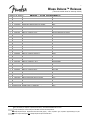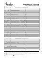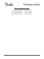
1
Blues Deluxe™ Reissue
(This is the model name for warranty claims)
p/n 2232200000 (120V)
SERVICE MANUAL
CONTENTS:
Notices................................................2
Specifications .....................................3
Service Notes.....................................4
Circuit Description..............................5
Parts Lists:
PCB Assembly ............................6
Chassis Assembly.......................8
Cabinet Assembly .......................8
End Item Assembly .....................9
Footswitch Assembly ................10
Service Diagram List ......................11
Fender Musical Instruments Corporation / 8860 East Chaparral Road, Suite 100 / Scottsdale, AZ 85250
Issued: July, 2005
2
Blues Deluxe™ Reissue
(This is the model name for warranty claims)
IMPORTANT NOTICE
• Copyright © 2005 FMIC. All rights reserved. All
information contained herein is CONFIDENTIAL
and PROPRIETARY and is the property of
Fender® Musical Instruments Corporation. It is
not to be sold or assigned to another party and is
disclosed solely for use by Fender Authorized
Service Centers for purposes of product service
and maintenance. All information is not to be
disclosed to others without the expressed
permission of Fender® Musical Instruments
Corporation. All specifications are subject to
change without notice. This information and any
copies produced electronically or otherwise must
be surrendered upon demand of Fender® Musical
Instruments Corporation.
• Parts marked with two asterisks (**) indicate the
required use of that specific part.
This is
necessary for RELIABILITY and SAFETY
requirements.
DO NOT USE A SUBSTITUTE!
PARTS LIST CODES
The description codes used in the itemized Parts Lists are defined below:
CAPACITOR CODES
CAP AE
= Aluminum Electrolytic
CAP CA
= Ceramic Axial
CAP CD
= Ceramic Disk
CAP CR
= Ceramic Radial
CAP MPF = Metalized Polyester Film
CAP MY
= Mylar
CAP PFF = Polyester Film/Foil
RESISTOR
RES CC
RES CF
RES FP
RES MF
RES MOX
RES WW
CODES
= Carbon Comp
= Carbon Film
= Flame Proof
= Metal Film
= Metal Oxide
= Wire Wound
HARDWARE CODES
BLX
= Black Oxide
CR
= Chrome Plated
HWH
= Hex Washer Head
M
= Machine Screw
NI
= Nickel Plated
OHP
= Oval Head Phillips
PB
= Particle Board
PHP
= Pan Head Phillips
PHPS
= Pan Head Phillips Sems
SMA
= Sheet Metal "A" Point
SMB
= Sheet Metal "B" Point
SS
= Stainless Steel
TF
= Thread Forming
ZI
= Zinc Plated
3
Blues Deluxe™ Reissue
(This is the model name for warranty claims)
SPECIFICATIONS
Model Name:
Blues Deluxe Reissue
Release Number:
(Not a model number)
PR 658
Part Numbers
(120V, 60Hz) US:
(110V, 60Hz) TW:
(240V, 50Hz) AUS:
(230V, 50Hz) UK:
(230V, 50Hz) ARG:
(230V, 50Hz) EUR:
(100V, 50Hz) JPN:
(220V, 60Hz) ROK:
2232200000
2232201000
2232203000
2232204000
2232205000
2232206000
2232207000
2232209000
Power Requirement:
180 W
Power Output:
40 W RMS into 8 or 4 ohms @ 5 %THD
Power Amp Sensitivity:
230mV for 40W into 8 or 4 ohms @ 5 %THD
Impedances
Input (Pre-Amp):
Pre Amp Out:
Pwr Amp In:
Speaker Complement:
Dimensions
Weight:
INPUT1: 34k ohms, INPUT2 : 68kOhms
1.5k ohms
2.7k ohms
Eminence 12", 8 ohm,
(P/N 0994812002)
Height:
Width:
Depth:
18.75 in ( 47.6 cm)
23.5 in ( 59.7 cm)
10.5 in (26.7 cm)
49.5 lbs (22.7 kg)
Product specifications are subject to change without notice
4
Blues Deluxe™ Reissue
(This is the model name for warranty claims)
SERVICE NOTES
1. CHASSIS REMOVAL is accomplished by first
removing two (2) screws from each cabinet side
panel and two (2) screws from the top of the
cabinet. Disconnect the ¼” speaker plug(s)
from the speaker jack(s) and then slide the
chassis toward the rear of the cabinet.
2. BLUES DELUXE REISSUE MAIN PCB REMOVAL is accomplished by removing the
following items: All Vacuum tubes, all knobs including washers and nuts (8), four (4) jacks,
nuts and washers. Disconnect the transformer
and primary leads at P1-P12, P15-18. Remove
(1) chassis ground screw, six (6) screws at the
standoffs attached from the bottom of the chassis.
3. BLUES DELUXE REISSUE BREAKAWAY
PCB REMOVAL is accomplished by disconnecting wires from P13-14 and P19-20 then
removing thirteen (13) screws which attach the
vacuum tube PCB to the chassis from the bottom. Also unsolder gray wire from the external
speaker jack and green wires at pilot lamp.
PCB EXCHANGE POLICY
Parts marked with a single asterisk (*) in the Part
Lists are not field replaceable. If a failure due to
one of these components is detected, please
contact the FMIC Customer Service Department to
order the complete PCB Assembly.
5
Blues Deluxe™ Reissue
(This is the model name for warranty claims)
CIRCUIT DESCRIPTION
PRE-AMPLIFIER
The guitar signal is input to J1 for high gain and J2
for lower gain. When both inputs are used, both
signals receive low gain. V1-A and V1-B provide
two gain stages while R6 provides clean volume
control. The tone stack, composed of R13,14,15
and associated components provide treble, bass
and middle tone control respectively. V2-A provides
gain lost in the tone stack. When the channel select
switch is depressed, relays K1 and K2 are
energized. This has the effect of disconnecting the
volume control, thereby increasing the gain of the
first stage while removing the short across R7, drive
control, allowing it to control the amount that V2-A
is overdriven. R26 is now in the circuit and is used
to control the volume of the overdriven signal. The
clean or distorted signals are input to opamp U1-A,
employed as a unity gain buffer to develop the
PREAMP out signal at J3. Opamps U2-A and U2-B
function as reverb tank drive and recovery
respectively. When an external signal is plugged
into J4, POWER AMP IN, the internal pre-amp
signal is diverted from the power amp and the
external signal instead is fed to the reverb drive and
the power amp.
POWER AMPLIFIER
R40 and R38 sum the signals from the preamp and
the reverb tank and feed them into the power
amplifier. V3-A and V3-B serve as phase splitters
.
which produce two out of phase signals for the
purpose of driving V4 and V5 which act as a pushpull pair in a class A-B power amplifier. T1 matches
the 6L6 plate impedance to the speaker load.
POWER SUPPLY
The line voltage is fed to T2’s primary through the
line fuse, F1, and the inrush current limiter, RT1.
The input voltage is then stepped up or down as
needed, rectified and filtered to produce the high X,
Y, Z and B+ voltage for the tubes as well as the +/16V rails for the opamps. A 6.3VAC secondary
powers the power indicator lamp and the tubes’
heaters.
FOOTSWITCH INTERFACE
A two button footswitch (P/N 0994056000) is
included for remote switching of the channels and
reverb. When the VAC signal is clamped by either
the internal (S2) or external (footswitch) diodes, a
positive or a negative level that is being compared
to a reference by comparators U3-A/B is changed,
causing the comparator outputs to change state.
U3-b senses the positive level change and
energizes K1 and K2. U3-A senses the negative
level change and turns on Q2 which mutes the
reverb. U4-A and associated circuitry act as a zero
crossing detector which mutes the preamp during
channel changes.
6
Blues Deluxe™ Reissue
(This is the model name for warranty claims)
PARTS LIST:
QTY.
1
1
2
1
1
1
1
2
1
1
5
1
1
1
1
4
2
8
16
2
2
2
6
4
1
3
1
3
2
2
21
2
4
1
1
3
2
1
1
1
2
2
2
1
1
1
2
1
1
2
1
2
PART #
REF
36621001
36470001
36468001
36469001
33095001
41269001
30936003
41256000
38698001
38701001
51406003
51458003
20917000
20909000
25951000
25995000
34788003
26730001
6260001
29690001
31019001
28119060
9512001
38689001
28459003
24819000
24820000
31040000
28494000
36954003
25802000
26368001
25116001
24953001
31065001
51658000
59922000
28039000
27255003
27278003
27281003
27272003
27286003
27262003
24823000
24853000
24833000
24845000
24854000
24855000
28503000
31901000
MAIN – PCB ASSEMBLY
DESCRIPTION
**PCB ASSY BLUES DELUXE REISSUE
RES FILM 1W 5% 6.8k LL
**RES MOX FP 1W 5% 10k LL
**RES MOX FP 1W 5% 470ohm LL
**RES MOX FP 1W 5% 4.7k LL
**RES MOX FP 1W 5% 1ohm LL
RES MOX 2W 5% 1.2kohm LL
CAP PFF RDL .0022uF 50V 5%
RES WW BT 5W 10% 470ohm
CAP CA 47pF 100V
CAP CA 470pF 50V LL
CAP CD 220pF 500V 10%
CAP CD 470pF 500V 10%
CAP CD 250pF 1000V 10%
CAP CD 47pF 1000V 10%
CAP CD 750pF 1000V 10%
CAP CD 8200pF 1000V 20%
CAP CR .1uF 50V 20% .2" LS
DIODE 1N4006 800V 1A
DIODE 1N4448 SIGNAL
DIODE HV 3kV 200mA
DIODE ZEN 1N5245B 15V 5% LL
DIODE ZEN 1N5353B 16V 5W 5%
CAP AE AX 22uF 25V 20%
CAP AE AX .47uF 100V 20%
CAP AE RDL 2.2uF 50V 20%
**CAP AE AX 22uF 500V +50%-10%
**CAP AE AX 47uF 350V 20%
CAP AE RDL 100uF 100V 20%
CAP AE RDL 1000uF 35V 20%
CAP AE RDL 22uF 63V 20%
FSTN TAB MALE .250x.032 PCB MT
RES CF 1/2W 5% 100ohm LL
RES CF 1/2W 5% 100k LL
RES CF 1/4W 5% 120 LL
RES CF 1/2W 5% 91k LL
JACK MONO R/A
JACK PHONE PCB STEREO PREMIUM LOW PROFILE
LED RED 5x5mm SLB-55VR3
CAP MPF .001uF 100V 10%
CAP MPF .1uF 63V 10%
CAP MPF .22uF 63V 10%
CAP MPF .047uF 63V 10%
CAP MPF .47uF 63V 10%
CAP MPF .0068uF 100V 10%
CAP MPF RDL .01uF 400V 10%
CAP MPF RDL .1uF 250V 10%
CAP MPF RDL .022uF 400V 10%
CAP MPF RDL .047uF 400V 10%
CAP MPF RDL .1uF 400V 10%
CAP MPF RDL .1uF 630V 10%
**THERMISTOR 10 ohm 5A C60-11
PIN MALE PCB .093 DIA.
REFERENCE DESIGNATION
R56
R75
R61-62
R74
R66
R97
C10
R78-79
C15
C13
C57-61
C23
C7
C28
C53
C62-65
C54-55
D3 D6-9 D11-12 D15
D16-17 D19-32
D4-5
D1-2
D13-14
C1 C8 C14 C21 C50 C56
C12 C16 C19-20
C47
C33,C35-36
34
C39 C42-43
C40-41
C38 C45
P1-21
R80-81
R4 R11 R16 R58
R24
R57
J1-2 J5
J3-4
D18
C22
C29
C4 C46
C3 C9
C17 C48
C52
C18
C25
C6 C24
C2
C5
C26-27
RT1
SP1-2
* Non-serviceable part. Replace complete parent assembly. See PCB EXCHANGE POLICY above.
Unique Fender® part. Order directly from the FMIC Customer Service Department.
** Safety Requirement part. Replacement must match Safety Agency…–Value, if specified –Type, if specified –Approval Mark(s) if on part.
** Both a unique Fender® part and a Safety Requirement part as defined above.
7
Blues Deluxe™ Reissue
(This is the model name for warranty claims)
PARTS LIST:
QTY.
1
1
2
1
2
1
1
1
2
7
5
9
2
1
8
1
1
1
6
1
3
1
1
1
1
1
1
3
4
1
2
1
3
1
2
2
6
2
2
2
2
3
2
PART #
37600000
41507000
41510000
47031000
47540000
37597000
27873000
24937001
24965001
24981001
24997001
25069001
25084001
28955001
24969001
24985001
24999001
24955001
25059001
29450001
24972001
24959001
24960001
24991001
25828001
24947001
24961001
24977001
24993001
25065001
28990001
28018001
24995001
26510001
41465003
REF
REF
36613000
28091000
31611000
16795000
0994005000
0994001XXX
MAIN – PCB ASSEMBLY
DESCRIPTION
CONTROL SNAPIN 100k B TAPER
CONTROL SNAPIN 1M 10A TAPER
CONTROL SNAPIN 25k B TAPER
CONTROL SNAPIN 25k 30C TAPER
CONTROL SNAPIN 250k 15A TAPER
CONTROL SNAPIN 250k 30A TAPER
Pot, vertical trimpot, 15mm
RES CF 1/4W 5% 10ohm LL
RES CF 1/4W 5% 1k LL
RES CF 1/4W 5% 10k LL
RES CF 1/4W 5% 100k LL
RES CF 1/4W 5% 1M LL
RES CF 1/4W 5% 10M LL
RES CF 1/4W 5% 130k LL
RES CF 1/4W 5% 1.5k LL
RES CF 1/4W 5% 15k LL
RES CF 1/4W 5% 150k LL
RES CF 1/4W 5% 180ohm LL
RES CF 1/4W 5% 220k LL
RES CF 1/4W 5% 240k LL
RES CF 1/4W 5% 2.7k LL
RES CF 1/4W 5% 330ohm LL
RES CF 1/4W 5% 390ohm LL
RES CF 1/4W 5% 39k LL
RES CF 1/4W 5% 430k LL
RES CF 1/4W 5% 47ohm LL
RES CF 1/4W 5% 470ohm LL
RES CF 1/4W 5% 4.7k LL
RES CF 1/4W 5% 47k LL
RES CF 1/4W 5% 470k LL
RES CF 1/4W 5% 51k LL
RES CF 1/4W 5% 510k LL
RES CF 1/4W 5% 68k LL
RES CF 1/4W 5% 9.1k LL
XSTR N-CH JFET J113 TO-92
CABLE JMPR 2 CKT .156 ROUND
CABLE JMPR 6 CKT .156 ROUND
RELAY DPDT DIP 24VOLT 8.3mA
SWITCH PUSH SLFLK SHORT STROKE
IC OP-AMP DUAL PC4560
IC OP-AMP DUAL TL072
TUBE 7025/12AX7A (CHINESE) FNDR GT
TUBE 6L6GC YL FNDR GT
REFERENCE DESIGNATION
R26
R14
R15 R39
R67
R6-7
R13
R82
R63
R41 R85
R27 R43 R46 R90-91 R93-94
R12 R19 R30 R42 R77
R3 R28 R32 R53-54 R86-87 R89 R92
R20-21
R18
R5 R10 R17 R31 R64-65 R76 R103
R102
R9
R34
R8 R35-36 R40 R59-60
R52
R37 R49-50
R84
R104
R22
R38
R99
R55
R33 R68 R88
R29 R45 R51 R96
R95
R47-48
R44
R1-2 R69
R23
Q1-2
PW4A PW4B
PW1A PW1B PW2A PW2B PW3A PW3B
K1-2
S1-2
U2-3
U1 U4
V1-3
V4-5
* Non-serviceable part. Replace complete parent assembly. See PCB EXCHANGE POLICY above.
Unique Fender® part. Order directly from the FMIC Customer Service Department.
** Safety Requirement part. Replacement must match Safety Agency…–Value, if specified –Type, if specified –Approval Mark(s) if on part.
** Both a unique Fender® part and a Safety Requirement part as defined above.
8
Blues Deluxe™ Reissue
(This is the model name for warranty claims)
PARTS LIST:
QTY.
0.09
1
2
6
6
4
2
1
1
1
8
1
1
1
1
1
1
21
1
1
1
8
1
1
1
1
4
1
1
1
3
1
3
PART #
REF
REF
REF
16352000
16440000
16444000
16473000
20424000
21550000
21642000
21741000
22004000
22707000
25718000
26038000
26116000
26541000
28069000
31184000
31625000
32219000
36570000
36620000
36702000
36958000
50438000
37039000
38900000
41701000
48356000
REF
53479000
65557000
53480000
DESCRIPTION
CHASSIS ASSY BLUES DLX REISSUE
TUBING SHRINK 3/16 BLACK
LABEL GROUNDING SEMKO
NUT HEX 3/8-32x3/32 TK NI(049)
STNDOFF RND AL 6-32x1x1/4
WASHER LOCK EXTERNAL #6 THIN C
SCRW M 8-32x1/2 PHP ZI
TUBE RING UNIVERSAL (277H-2)
JACK PHONE TIP SHUNT 12A
PILOT LIGHT #T47
HOLDER IDAL LITE ASSY PIL
NUT KEPS #8-32 ZINC
CHOKE FILTER
JEWEL PILOT LITE RED #20
BUSHING SR .625x.062x37/64 BLK
BUSHING SR .500x.063x7/16 BLK
**CORD PWR ASSY W/.250 TAB 120V
BUSHING SNAP 3/4x1-1/8 WHT
SCRW M6-32x1/4 PHPS BLX ITLW
NUT HOLDER PILOT LIGHT 1/
COLLAR-PILOT LIGHT
SWITCH TOGGLE DPST W/NUTS
KNOB CHICKEN HEAD 1/4 SHFT (BLAC
**FUSE HOLDER 3AG FINGER GRIP
**XFMR PWR 120v HR DLX/VIBVB
**XFMR AUDIO OUTPUT 40W
SWITCH TOGGLE SPST W/NUTS
SCRW TF 6-32X1/4 PHP ZI
JACK PHONE TRANSFER 13A
SHIELD SNAP-IN TUBE
WIRE SET CHS H/R DVL/DLX
NUT HEX 7/16 20X1/8 NI
PANEL TOP CHRM BLUES REISSUE
WASHER FLAT .442 X.692 NI
PARTS LIST:
QTY.
1
6
6
5
6
2
AR
AR
7”
7”
PART #
041989000
036618000
049563000
022327000
0041989003
036618000
069393000
041987000
036343000
REF
REF
REF
CHASSIS ASSEMBLY
REFERENCE DESIGNATION
FT
EA
EA
EA
EA
EA
EA
EA
EA
EA
EA
EA
EA
EA
EA
EA
EA
EA
EA
EA
EA
EA
EA
EA
EA
EA
EA
EA
EA
EA
EA
EA
CABINET ASSEMBLY
DESCRIPTION
CABINET ASSY BLUES DELUXE
SCREW M 6-32 X 1/12 OHP BRONZE
WASHER C’SINK #6 ANTQ BRONZE
WASHER FLAT 8 X 7/16 NI
GRILLE ASSY BLUES DELUXE
SCREW BAFFLE
NUT 6-32 HEX EXT LOCK
STRIP BOTTOM BLUES DELUXE
TWEED COVERING
TAPE ALUMINUM 7” X 60 TDS
VELCRO STRIP HOOK 1.5” wd BLACK
VELCRO STRIP LOOP 1.5” wd BLACK
REFERENCE DESIGNATION
* Non-serviceable part. Replace complete parent assembly. See PCB EXCHANGE POLICY above.
Unique Fender® part. Order directly from the FMIC Customer Service Department.
** Safety Requirement part. Replacement must match Safety Agency…–Value, if specified –Type, if specified –Approval Mark(s) if on part.
** Both a unique Fender® part and a Safety Requirement part as defined above.
9
Blues Deluxe™ Reissue
(This is the model name for warranty claims)
PARTS LIST:
QTY.
4
4
4
4
4
1
PART #
026625000
024653000
022483000
064162000
037247000
036784000
DESCRIPTION
SCREW WOOD 8 X 1 FH
GLIDE CABINET NICKEL PLATED
INSERT GLIDE CUSHION 1.02 DIA
NUT T 8-32 X ½ STR 3 PRNG BLX
SCREW M 8 -32 X 1 OHP NI
HANDLE, MOLDED
PARTS LIST:
QTY.
1
1
6
2
1
1
1
3
6
0.002
1
1
1
1
4
1
1
1
1
1
1
1
4.5
1
1
1
1
1
1
PART #
2232200000
12582000
15990000
26459000
28453000
50394000
31849000
29828000
36619000
36650000
0994812002
38566000
41989000
47485000
47821000
REF
65562000
0994056000
REF
REF
REF
65558000
REF
REF
REF
REF
59718000
REF
9906900590
PART #
0994056000
*
*
*
*
*
*
*
*
*
REFERENCE DESIGNATION
END ITEM ASSEMBLY
DESCRIPTION
BLUES DELUXE REISSUE
CLAMP CABLE NYL SCRW MNT 1/4
SCRW M 10-32x3/4 THP NI
WSHR FLAT 6x3/8 ZI
PAD CARDBOARD REVERB #12FN86
REVERB UNIT 4 SPRING 4EB3C1B
REVERB BAG
SCRW PB 8x3/4 PHP ZI
SCREW M 10-32x1-1/2 THP NI
PIN ESCUTCHEON #18x3/8 NI
SPKR 12" 8ohm 50W
CABLE ASSY SPKR RT ANG 13-1/2"
CAB ASSY HR /BLUES DLX TWEED
COVER,BROWN BLUES/HR DLX
SCRW M 10-32 3/4 THP STL BLX
LABEL TUBE BLUES DLX REISSUE
MANUAL OWNERS BLUES DLX REISSUE
FTSW 2 BTN CH/RVB
LABEL CSA C/US
LABEL SERIAL B BLK ON CHRM
NAMEPLATE TWEED AMPS
PANEL REAR BLUES DLX REISSUE
FOAM TAPE 1/4" 1/16 3M4516
TAG WARRANTY 5 YR FENDERHANG TAG GROOVE TUBE
REGISTRATION CARD
STABILIZER TUBE HOT ROD
CHS ASSY BLUES DLX REISSUE 120V
CLAMP CABLE NYL ADHESIVE
PARTS LIST:
QTY.
1
1
2
1
8
1
1
1
1
1
CABINET ASSEMBLY
REFERENCE DESIGNATION
FOOTSWITCH ASSY
DESCRIPTION
FTSW 2 BTN CH/RVB
NUT HEX 12mm X 1mm NI
WSHR NYL 0.485 X 0.775 X 0.150 TK
CABLE ASSY FTSW RT ANG 12’ (N.S.)
SCRW SMB 6 X 3/8 PH PHS BLX
HSG END CUP RIGHT FTSW
HSG END CUP LEFT FTSW
TOP PLATE
HSG FTSW 2 BUTTON
PCB ASSSY FT SW 2 BUTTON
REFERENCE DESIGNATION
* Non-serviceable part. Replace complete parent assembly. See PCB EXCHANGE POLICY above.
Unique Fender® part. Order directly from the FMIC Customer Service Department.
** Safety Requirement part. Replacement must match Safety Agency…–Value, if specified –Type, if specified –Approval Mark(s) if on part.
** Both a unique Fender® part and a Safety Requirement part as defined above.
10
Blues Deluxe™ Reissue
(This is the model name for warranty claims)
Service Diagram List
Service Diagram (0065561000)............. Blues Deluxe Reissue
PCB Assembly (0065560000)............. Blues Deluxe Reissue
Chassis Assembly (0065552000)............. Blues Deluxe Reissue
End Item Assembly (2232200000)............. Blues Deluxe Reissue