1
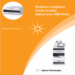
Agilent 1260 Infinity
Quaternary LC VL
System Manual and
Quick Reference
Agilent Technologies
Notices
© Agilent Technologies, Inc. 2010
Warranty
No part of this manual may be reproduced
in any form or by any means (including electronic storage and retrieval or translation
into a foreign language) without prior agreement and written consent from Agilent
Technologies, Inc. as governed by United
States and international copyright laws.
The material contained in this document is provided “as is,” and is subject to being changed, without notice,
in future editions. Further, to the maximum extent permitted by applicable
law, Agilent disclaims all warranties,
either express or implied, with regard
to this manual and any information
contained herein, including but not
limited to the implied warranties of
merchantability and fitness for a particular purpose. Agilent shall not be
liable for errors or for incidental or
consequential damages in connection
with the furnishing, use, or performance of this document or of any
information contained herein. Should
Agilent and the user have a separate
written agreement with warranty
terms covering the material in this
document that conflict with these
terms, the warranty terms in the separate agreement shall control.
Manual Part Number
G1311-90310
Edition
06/2010
Printed in Germany
Agilent Technologies
Hewlett-Packard-Strasse 8
76337 Waldbronn
This product may be used as a
com-ponent of an in vitro diagnostic
sys-tem if the system is registered
with the appropriate authorities and
com-plies with the relevant regulations. Otherwise, it is intended only
for gen-eral laboratory use.
receive no greater than Restricted Rights as
defined in FAR 52.227-19(c)(1-2) (June
1987). U.S. Government users will receive
no greater than Limited Rights as defined in
FAR 52.227-14 (June 1987) or DFAR
252.227-7015 (b)(2) (November 1995), as
applicable in any technical data.
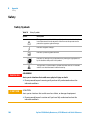
Safety Notices
CAUTION
A CAUTION notice denotes a
hazard. It calls attention to an
operating procedure, practice, or
the like that, if not correctly performed or adhered to, could
result in damage to the product
or loss of important data. Do not
proceed beyond a CAUTION
notice until the indicated conditions are fully understood and
met.
Technology Licenses
The hardware and/or software described in
this document are furnished under a license
and may be used or copied only in accordance with the terms of such license.
Restricted Rights Legend
If software is for use in the performance of a
U.S. Government prime contract or subcontract, Software is delivered and licensed as
“Commercial computer software” as
defined in DFAR 252.227-7014 (June 1995),
or as a “commercial item” as defined in FAR
2.101(a) or as “Restricted computer software” as defined in FAR 52.227-19 (June
1987) or any equivalent agency regulation
or contract clause. Use, duplication or disclosure of Software is subject to Agilent
Technologies’ standard commercial license
terms, and non-DOD Departments and
Agencies of the U.S. Government will
WA R N I N G
A WARNING notice denotes a
hazard. It calls attention to an
operating procedure, practice,
or the like that, if not correctly
performed or adhered to, could
result in personal injury or
death. Do not proceed beyond a
WARNING notice until the indicated conditions are fully understood and met.
Agilent 1260 Infinity Quaternary LC VL Manual and Quick Reference
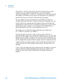
In This Book
In This Book
This book describes the Agilent 1260 Infinity Quaternary LC VL
1 Introduction
This chapter gives an introduction to the Agilent 1260 Infinity Quaternary LC
VL, the underlying concepts and the features of the Agilent 1260 Infinity
Quaternary LC VL.
2 Specifications
This chapter provides information about specifications for the LC system.
3 Optimization of the Agilent 1260 Infinity Quaternary LC VL
This chapter considers how to apply the theory and use the features of the LC
system to develop optimized separations.
4 System Setup and Installation
This chapter includes information on software installation, stack
configurations and preparing the system for operation.
5 Quick Start Guide
This chapter provides information on data acquisition and data analysis with
the Agilent 1260 Infinity Quaternary LC VL.
6 Appendix
This chapter provides addition information on safety, legal, web and the Edit
Entire Method.
Agilent 1260 Infinity Quaternary LC VL Manual and Quick Reference
3
Contents
Contents
1 Introduction
7
Introduction to the Agilent 1260 Infinity Quaternary LC VL 8
Features of the Agilent 1260 Infinity Quaternary LC VL 10
System Components 11
Optimizing the Stack Configuration 12
Quaternary pump 17
Autosampler 19
Thermostatted column compartment 24
Detector 25
2 Specifications
37
Physical Specifications 38
Performance Specifications 40
3 Optimization of the Agilent 1260 Infinity Quaternary LC VL
49
Optimizing the Pump 50
Optimizing the Autosampler 54
Optimizing the Thermostatted Column Compartment 61
Optimizing the Detector Regarding to the System 62
Optimizing Detection with DAD 63
Optimizing Detection with VWD 78
4 System Setup and Installation
83
Installing Software 84
Installing the Modules 85
5 Quick Start Guide
91
Preparing the System 92
Setting Up the Method 97
4
Agilent 1260 Infinity Quaternary LC VL Manual and Quick Reference
Contents
6 Appendix
99
Safety 100
The Waste Electrical and Electronic Equipment Directive
Lithium Batteries Information 104
Radio Interference 105
Sound Emission 106
Solvent Information 107
UV-Radiation 108
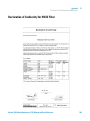
Declaration of Conformity for HOX2 Filter 109
Agilent Technologies on Internet 110
Agilent 1260 Infinity Quaternary LC VL Manual and Quick Reference
103
5
Contents
6
Agilent 1260 Infinity Quaternary LC VL Manual and Quick Reference
Agilent 1260 Infinity Quaternary LC VL Manual and Quick Reference
1
Introduction
Introduction to the Agilent 1260 Infinity Quaternary LC VL
Concept of the Quaternary LC VL System 8
System Properties 8
Features of the Agilent 1260 Infinity Quaternary LC VL
System Components
8
10
11
Optimizing the Stack Configuration
One Stack Configuration 12
Two Stack Configuration 15
12
Quaternary pump 17
Hydraulic Path 18
Autosampler 19
Sequences 21
Thermostatted column compartment
24
Detector 25
Diode-Array Detector (DAD) 25
Variable Wavelength Detector (VWD)
30
This chapter gives an introduction to the Agilent 1260 Infinity Quaternary LC VL,
the underlying concepts and the features of the Agilent 1260 Infinity
Quaternary LC VL.
Agilent Technologies
7
1
Introduction
Introduction to the Agilent 1260 Infinity Quaternary LC VL
Introduction to the Agilent 1260 Infinity Quaternary LC VL
Concept of the Quaternary LC VL System
The Agilent 1260 Infinity Quaternary LC VL offers the most flexibility for
solvent selection and automation in HPLC method development, research and
all HPLC applications requiring continuous access to a wide range of solvent
choices. The availability to rapidly switch between methods using different
solvents and the capability of using binary, ternary or quaternary solvent
gradients make the Agilent 1260 Infinity Quaternary LC VL the most flexible
system on the market.
System Properties
The Agilent 1260 Infinity Quaternary LC VL is ideally suited for multi-method,
high-throughput workflows. It offers:
• Convenient access to four solvents for isocratic or gradient analysis for
rapid method development and speed up preparation of mobile phases and
flushing the HPLC system.
• Pressure range up to 400 bar.
• A wide flow range up to 10 mL/min and a delay volume of 800 – 1100 µL
supports narrow-bore, standard and semi-preparative applications.
• Easy programming and control through the Instant Pilot G4208A (requires
firmware B.02.08 or above) (p/n G4208-67001) or through an Agilent Data
System.
• Included micro vacuum degasser offers high degassing efficiency for
trouble-free operation and highest performance and completely eliminates
the need for helium sparging.
• Direct front access for quick exchange of maintenance parts.
• Fast problem identification by self-diagnostics, built-in log books and
preprogrammed test methods.
8
Agilent 1260 Infinity Quaternary LC VL Manual and Quick Reference
Introduction
Introduction to the Agilent 1260 Infinity Quaternary LC VL
1
• Early maintenance feedback (EMF) that continuously tracks long-term
instrument usage and user-defined limits with feedback message when limit
is exceeded.
• Upgradeability and expandability with the complete range of Agilent 1200
Infinity Series HPLC modules.
• Agilent Data System helps you manage your lab for best chromatographic
quality with intuitive diagnostic and monitor capabilities and alert
functions to notify you of problems.
Agilent 1260 Infinity Quaternary LC VL Manual and Quick Reference
9
1
Introduction
Features of the Agilent 1260 Infinity Quaternary LC VL
Features of the Agilent 1260 Infinity Quaternary LC VL
The Agilent 1260 Infinity Quaternary LC VL is designed to offer the greatest
flexibility for performing analytical liquid chromatography using all types of
current and emergent column technologies.
The quaternary system as described in this manual offers:
• Gradients of up to 4 different solvents.
• Pressure range up to 400 bar.
• Sophisticated pump control to deliver very low chromatographic noise and
very low acoustic noise for better results and better working environment.
• Degasser and automatic purge valve integrated into pump module.
• Variable volume autosampler with reduced delay volume, reduced
carryover and the option to operate as a fixed loop autosampler.
• Thermostated column compartment with a pressure range up to 600 bar
• Choice of detectors (a set of different flow cells is available for different
detectors to fit application needs regarding flow ranges (nano scale, micro
scale, standard and preparative applications) and pressures):
• Diode-array detector with greatly enhanced sensitivity and baseline
stability using cartridge cell system with optofluidic waveguides (data
collection rate up to 80 Hz with full spectral information) or
• Variable wavelength detector.
10
Agilent 1260 Infinity Quaternary LC VL Manual and Quick Reference
1
Introduction
System Components
System Components
Solvent cabinet
The solvent cabinet is a case to keep four bottles with solvent standing framed
and stable, so that they can be connected by solvent tubings to the LC System.
Quaternary pump
The quaternary pump generates gradients by low pressure mixing from four
individual solvent channels.
Autosampler with/without thermostat
The autosampler is specifically designed for the Agilent 1200 Infinity Series
system for increased analysis speed with sensitivity, resolution, and precision.
Thermostatted column compartment
This stackable temperature-controlled column compartment is used for
heating and cooling in order to meet extreme requirements of retention time
reproducibility.
Diode array or variable wavelength detector
Signals triggered by UV absorption are sampled to be converted to electrical
signals in order for display and software handling.
The Agilent 1260 Infinity Quaternary LC VL are described in more detail in
the following sections. All modules are stackable, see “One Stack
Configuration” on page 12 and “Two Stack Configuration” on page 15.
Agilent 1260 Infinity Quaternary LC VL Manual and Quick Reference
11
1
Introduction
Optimizing the Stack Configuration
Optimizing the Stack Configuration
You can ensure optimum performance by installing the system in following
configurations. These configurations optimize the system flow path, ensuring
minimum delay volume.
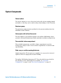
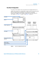
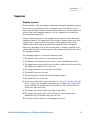
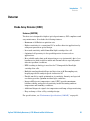
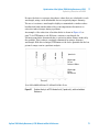
One Stack Configuration
Ensure optimum performance by installing the modules of the Agilent 1260
Infinity LC System in the following configuration (see Figure 1 on page 13 and
Figure 2 on page 14). This configuration optimizes the flow path for minimum
delay volume and minimizes the bench space required.
12
Agilent 1260 Infinity Quaternary LC VL Manual and Quick Reference
Introduction
Optimizing the Stack Configuration
1
HdakZciXVW^cZi
Ejbe
AdXVajhZg^ciZg[VXZ
6jidhVbeaZg
I]ZgbdhiViiZY
XdajbcXdbeVgibZci
9ZiZXidg
Figure 1
Recommended Stack Configuration (Front View)
Agilent 1260 Infinity Quaternary LC VL Manual and Quick Reference
13
1
Introduction
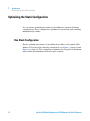
Optimizing the Stack Configuration
68edlZg
86CWjhXVWaZ
idadXVajhZg^ciZg[VXZ
GZbdiZXVWaZ
86CWjhXVWaZ
A6CidXdcigdahd[ilVgZ
adXVi^dcYZeZcYhdcYZiZXidg
6cVad\YZiZXidgh^\cVa
&dg'djiejiheZgYZiZXidg
Figure 2
14
Recommended Stack Configuration (Rear View)
Agilent 1260 Infinity Quaternary LC VL Manual and Quick Reference
Introduction
Optimizing the Stack Configuration
1
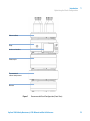
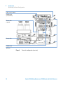
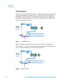
Two Stack Configuration
To avoid excessive height of the stack when the autosampler thermostat is
added to the system it is recommended to form two stacks. Some users prefer
the lower height of this arrangement even without the autosampler
thermostat. A slightly longer capillary is required between the pump and
autosampler. See Figure 3 on page 15 and Figure 4 on page 16.
>chiVciE^adi
9ZiZXidg
8dajbcXdbeVgibZci
6jidhVbeaZg
I]ZgbdhiVi[dgi]Z6AH
dei^dcVa
HdakZciXVW^cZi
9Z\VhhZgdei^dcVa
Ejbe
Figure 3
Two stack configuration (front view)
Agilent 1260 Infinity Quaternary LC VL Manual and Quick Reference
15
1
Introduction
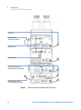
Optimizing the Stack Configuration
A6CidXdcigdahd[ilVgZ
86C7jhXVWaZ
id>chiVciE^adi
I]ZgbdXVWaZ
dei^dcVa
68EdlZg
GZbdiZXVWaZ
68EdlZg
86C7jhXVWaZ
68EdlZg
Figure 4
16
Two stack configuration (rear view)
Agilent 1260 Infinity Quaternary LC VL Manual and Quick Reference
Introduction
Quaternary pump
1
Quaternary pump
The quaternary pump is based on a two-channel, dual-plunger in-series design
which comprises all essential functions that a solvent delivery system has to
fulfill. Metering of solvent and delivery to the high-pressure side are
performed by one pump assembly which can generate pressure up to 400 bar.
Degassing of the solvents is done in a built-in vacuum degasser. Solvent
compositions are generated on the low-pressure side by a high-speed
proportioning valve (MCGV).
The pump assembly includes a pump head with a passive inlet valve and an
outlet valve. A damping unit is connected between the two plunger chambers.
A purge valve including a PTFE frit is fitted at the pump outlet for convenient
priming of the pump head.
An active seal wash (optional) is available for applications using concentrated
buffers as solvents.
Agilent 1260 Infinity Quaternary LC VL Manual and Quick Reference
17
1
Introduction
Quaternary pump
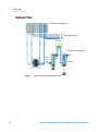
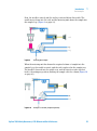
Hydraulic Path
KVXjjbX]VbWZg9Z\VhhZg
;gdbhdakZciWdiiaZh
9VbeZg
IdhVbea^c\jc^iVcYXdajbc
>caZi
kVakZ
DjiaZi
kVakZ
IdlVhiZ
Figure 5
18
Hydraulic Path of the Quaternary Pump
Agilent 1260 Infinity Quaternary LC VL Manual and Quick Reference
Introduction
Autosampler
1
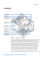
Autosampler
6cVani^XVa]ZVY
HVbea^c\Jc^i
IgVchedgiVhhZbWan
6HBWdVgY
EdlZghjeean
K^VaIgVn
<g^eeZg6gb
CZZYaZhZVi
Hl^iX]^c\KVakZ
Figure 6
Overview of the Autosampler
The Agilent 1260 Infinity Autosampler is designed to offer the well-established
Agilent flow-through design with variable volume injection and to achieve
extremely low carryover. The small hydraulic volume of the flow path is suited
to fast gradients and the ability to use overlapped injections and automatic
delay volume reduction (ADVR) contribute to faster cycle times and even
faster gradient delivery to the column. The system draws exactly the set
volume of sample solution without waste and achieves high reproducibility
across the whole range of possible injection volume. The autosampler is
controlled from G4208 A Instant Pilot or from the Agilent Data System.
Three sample-rack sizes are available. The standard full-size rack holds
100 × 1.8 mL vials, while the two half-size racks provide space for 40 × 1.8 mL
Agilent 1260 Infinity Quaternary LC VL Manual and Quick Reference
19
1
Introduction
Autosampler
vials and 15 × 6 mL vials respectively. Any two half-size rack trays can be
installed in the autosamplers simultaneously. A specially designed
sample-rack holding 100 × 1.8 mL vials is available for use with thermostatted
autosamplers. The half-size racks trays are not designed for an optimal heat
transfer when they are used with a thermostatted autosampler.
The autosamplers transport mechanism uses an X-Z-Theta movement to
optimize vial pick-up and return. Vials are picked up by the gripper arm, and
positioned below the sampling unit. The gripper transport mechanism and
sampling unit are driven by motors. Movement is monitored by optical sensors
and optical encoders to ensure correct operation. The metering device is
always flushed after injection to ensure minimum carry-over.
The module uses an analytical head providing injection volumes from
0.1 to 100 µL for pressures up to 600 bar.
The six-port injection valve unit (only 5 ports are used) is driven by a
high-speed hybrid stepper motor. During the sampling sequence, the valve unit
bypasses the autosampler, and directly connects the flow from the pump to the
column. During injection and analysis, the valve unit directs the flow through
the autosampler which ensures that the sample is injected completely into the
column, and that any sample residue is removed from the metering unit and
needle from before the next sampling sequence begins. Different valves are
available.
Control of the vial temperature in the thermostatted autosampler is achieved
using the additional Agilent 1260 Infinity ALS thermostat. Details of this
module are given in the Agilent 1260 Infinity Autosampler Thermostat
manual.
20
Agilent 1260 Infinity Quaternary LC VL Manual and Quick Reference
Introduction
Autosampler
1
Sequences
Sampling sequence
The movements of the autosampler components during the sampling sequence
are monitored continuously by the autosampler processor. The processor
defines specific time windows and mechanical ranges for each movement. If a
specific step of the sampling sequence can’t be completed successfully, an
error message is generated.
Solvent is bypassed from the autosamplers by the injection valve during the
sampling sequence. The sample vial is selected by a gripper arm from a static
sample rack, or from external vial positions. The gripper arm places the
sample vial below the injection needle. The required volume of sample is
drawn into the sample loop by the metering device. Sample is applied to the
column when the injection valve returns to the mainpass position at the end of
the sampling sequence.
The sampling sequence occurs in the following order:
1 The injection valve switches to the bypass position.
2 The plunger of the metering device moves to the initialization position.
3 The gripper arm moves from the home position, and selects the vial. At the
same time, the needle lifts out of the seat.
4 The gripper arm places the vial below the needle.
5 The needle lowers into the vial.
6 The metering device draws the defined sample volume.
7 The needle lifts out of the vial.
8 If the automated needle wash is selected (see “Using the Automated Needle
Wash” on page 54), the gripper arm replaces the sample vial, positions the
wash vial below the needle, lowers the needle into the vial, then lifts the
needle out of the wash vial.
9 The gripper arm checks if the safety flap is in position.
10 The gripper arm replaces the vial, and returns to the home position.
Simultaneously, the needle lowers into the seat.
11 The injection valve switches to the mainpass position.
Agilent 1260 Infinity Quaternary LC VL Manual and Quick Reference
21
1
Introduction
Autosampler
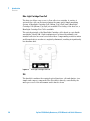
Injection sequence
Before the start of the injection sequence, and during an analysis, the injection
valve is in the mainpass position (Figure 7 on page 22). In this position, the
mobile phase flows through the autosamplers metering device, sample loop,
and needle, ensuring all parts in contact with sample are flushed during the
run, thus minimizing carry-over.
Figure 7
Mainpass Position
When the sample sequence begins, the valve unit switches to the bypass
position (Figure 8 on page 22). Solvent from the pump enters the valve unit at
port 1, and flows directly to the column through port 6.
Figure 8
22
Bypass Position
Agilent 1260 Infinity Quaternary LC VL Manual and Quick Reference
Introduction
Autosampler
1
Next, the needle is raised, and the vial is positioned below the needle. The
needle moves down into the vial, and the metering unit draws the sample into
the sample loop (Figure 9 on page 23).
Figure 9
Drawing the Sample
When the metering unit has drawn the required volume of sample into the
sample loop, the needle is raised, and the vial is replaced in the sample tray.
The needle is lowered into the needle seat, and the injection valve switches
back to the mainpass position, flushing the sample onto the column (Figure 10
on page 23).
Figure 10
Mainpass Position (Sample Injection)
Agilent 1260 Infinity Quaternary LC VL Manual and Quick Reference
23
1
Introduction
Thermostatted column compartment
Thermostatted column compartment
The Agilent 1260 Infinity Thermostatted Column Compartment is a stackable
temperature-controlled column compartment for LC. It is used for heating and
cooling to meet extreme requirements of retention time reproducibility.
The main features are:
• Peltier heating and cooling from 10 degrees below ambient up to 80 °C with
high heating and cooling speeds for maximum application flexibility and
stability.
• Holds up to three 30 cm columns and optimized design gives minimum dead
volumes and maximum efficiency.
• Two independently programmable heat exchangers contribute volumes of
only 3 µL and 6 µL.
• Electronic column-identification module as standard for GLP
documentation of column type and major column parameters.
• Optional high-quality Rheodyne® column switching valves with ceramic
stator-face assemblies for prolonged lifetime.
For specifications, see “Performance Specifications (G1316A)” on page 41.
24
Agilent 1260 Infinity Quaternary LC VL Manual and Quick Reference
1
Introduction
Detector
Detector
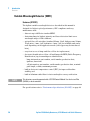
Diode-Array Detector (DAD)
Features (G4212B)
The detector is designed for highest optical performance, GLP compliance and
easy maintenance. It includes the following features:
• Maximum of 80 Hz data acquisition rate.
• Higher sensitivity for conventional LC as well as ultra fast applications by
using next generation optical design.
• Increased sensitivity with 60 mm Max-Light cartridge flow cell.
• Optimized cell geometry for less peak dispersion for narrow bore
applications.
• More reliable and robust peak integration process (automated) due to less
baseline noise/drift/refractive index and thermal effects especially under
ultra fast gradient conditions.
• RFID tracking technology is used for the UV-lamp and the Max-Light
cartridge flow cells.
• Multiple wavelength and full spectral detection at 80 Hz sampling rate,
keeping up with the analysis speed of ultra-fast LC.
• Fixed 4 nm slit for rapid optimization of sensitivity, linearity and spectral
resolution provides optimum incident light conditions .
• Improved Electronic temperature control (ETC) provides maximum
baseline stability and practical sensitivity under fluctuating ambient
temperature and humidity conditions.
• Additional diagnostic signals for temperature and lamp voltage monitoring.
• Easy exchange of flow cell by cartridge design.
For specifications, see “Performance Specifications (G4212B)” on page 43.
Agilent 1260 Infinity Quaternary LC VL Manual and Quick Reference
25
1
Introduction
Detector
Optical System
The optical system of the detector is shown in Figure 11 on page 26
Figure 11
Optical System of the Detector
1
UV-lamp
2
Lamp mirror
3
Flow cell
4
Fold mirror
5
Micro slit
6
Grating
7
Array
The illumination source is a deuterium-arc-discharge lamp [1] for the
ultraviolet (UV) wavelength range. Its light is focused by a lamp mirror [2]
onto the entrance of the Max-light cartridge flow cell [3] with optofluidic
waveguides. The light leaves the Max-light cartridge flow cell at the other side
and is focused by the fold mirror [4] through the slit assembly [5] onto a
holographic grating [6] light being dispersed onto the diode array [7]. This
allows simultaneous access to all wavelength information.
26
Agilent 1260 Infinity Quaternary LC VL Manual and Quick Reference
Introduction
Detector
1
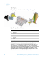
Lamp
The light source for the UV-wavelength range is a long-life UV-lamp with RFID
tag. As a result of plasma discharge in low-pressure deuterium gas, the lamp
emits light over the 190 nm to approximately 800 nm wavelength range.
Figure 12
UV-Lamp
Agilent 1260 Infinity Quaternary LC VL Manual and Quick Reference
27
1
Introduction
Detector
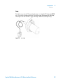
Max-Light Cartridge Flow Cell
The detector allows easy access to flow cells via a cartridge. A variety of
optional flow cells can be inserted using the same quick, simple mounting
system. A Max-Light Cartridge Cell (10 mm, V(σ) 1.0 µL) and a Max-Light
Cartridge Cell (60 mm, V(σ) 4 µL) are available. For testing of the detector, a
Max-Light Cartridge Test Cell is available.
The optical principle of the Max-Light Cartridge cell is based on opto-fluidic
waveguides. Nearly 100 % light transmission is achieved by utilizing total
internal reflection in a non-coated silica fiber. Compromising refractive index
and thermal effects are almost completely eliminated, resulting in significantly
less baseline drift.
Figure 13
Max-Light Cartridge Flow Cell
Slit
The fixed slit combines the required optical functions - slit and shutter - in a
simple and compact component. The slit width is directly controlled by the
micro-processor of the instrument and is fixed to 4 nm.
28
Agilent 1260 Infinity Quaternary LC VL Manual and Quick Reference
Introduction
Detector
1
Grating and Diode Array
The combination of dispersion and spectral imaging is accomplished by using
a concave holographic grating. The grating separates the light beam into all its
component wavelengths and reflects the light onto the photodiode array.
The diode array is a series of 1024 individual photodiodes and control circuits
located on a ceramic carrier. It has a wavelength range from 190 – 640 nm
and the sampling interval is ∼0.5 nm.
Figure 14
Grating and diode array
Agilent 1260 Infinity Quaternary LC VL Manual and Quick Reference
29
1
Introduction
Detector
Variable Wavelength Detector (VWD)
Features (G1314F)
The Agilent variable wavelength detectors described in this manual is
designed for highest optical performance, GLP compliance and easy
maintenance with:
• data rate up to 80 Hz for standard-HPLC
• deuterium lamp for highest intensity and lowest detection limit over a
wavelength range of 190 to 600 nm,
• optional flow-cell cartridges (standard 10 mm, 14 µL; high pressure 10 mm,
14 µL; micro 3 mm, 2 µL; semi-micro 6 mm, 5 µL) are available and can be
used depending on the application needs (other types may be introduced
later),
• easy front access to lamp and flow cell for fast replacement,
• electronic identification of flow cell and lamp with RFID (Radio Frequency
Identification) tag for unambiguous identification,
• lamp information: part number, serial number, production date,
ignitions, burn time
• cell information: part number, serial number, production date, nominal
path length, volume, maximum pressure
• built-in electronic temperature control (ETC) for improved baseline
stability, and
• built-in holmium oxide filter for fast wavelength accuracy verification.
NOTE
This detectors cannot be operated with a G1323B Control Module. Use the Instant Pilot
(G4208A) as local controller.
For specifications refer to “Performance Specifications (G1314F)” on page 44.
30
Agilent 1260 Infinity Quaternary LC VL Manual and Quick Reference
Introduction
Detector
1
Optical System Overview
The optical system of the detector is shown in the figure below. Its radiation
source is a deuterium-arc discharge lamp for the ultraviolet (UV) wavelength
range from 190 to 600 nm. The light beam from the deuterium lamp passes
through a lens, a filter assembly, an entrance slit, a spherical mirror (M1), a
grating, a second spherical mirror (M2), a beam splitter, and finally through a
flow cell to the sample diode. The beam through the flow cell is absorbed
depending on the solutions in the cell, in which UV absorption takes place,
and the intensity is converted to an electrical signal by means of the sample
photodiode. Part of the light is directed to the reference photodiode by the
beam splitter to obtain a reference signal for compensation of intensity
fluctuation of the light source. A slit in front of the reference photodiode cuts
out light of the sample bandwidth. Wavelength selection is made by rotating
the grating, which is driven directly by a stepper motor. This configuration
allows fast change of the wavelength. The cutoff filter is moved into the
lightpath above 370 nm to reduce higher order light.
9ZjiZg^jbaVbe
;^aiZgVhhZbWan
:cigVcXZha^i
AZch
B^ggdgB&
HVbeaZY^dYZ
<gVi^c\
;adlXZaa
B^ggdgB'
7ZVbhea^iiZg
GZ[ZgZcXZY^dYZ
Figure 15
Optical Path of the Variable Wavelength Detector
Agilent 1260 Infinity Quaternary LC VL Manual and Quick Reference
31
1
Introduction
Detector
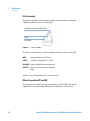
Flow Cell
A variety of flow-cell cartridges can be inserted using the same quick and
simple mounting system.
The flow cells have an integrated RFID tag that contains the flow cell specific
information (e.g. part number, cell volume, path length, ...). A RFID tag reader
reads out this information and transfers it to the user interface.
G;>9iV\
Figure 16
Table 1
Flow Cell with RFID tag
Flow Cell Data
STD
Semi-micro
Micro
High Pressure
Maximum pressure
40 (4)
40 (4)
120 (12)
400 (40)
bar
Path length
10 (conical)
6 (conical)
3 (conical)
10 (conical)
mm
Volume
14
5
2
14
µL
Inlet i.d.
0.17
0.17
0.12
0.17
mm
Inlet length
750
750
310
310
mm
Outlet i.d.
0.25
0.25
0.17
0.25
mm
Outlet length
120
120
120
120
mm
Materials in contact
with solvent
SST, quartz, PTFE,
PEEK
SST, quartz, PTFE
SST, quartz, PTFE
SST, quartz, Kapton
32
Agilent 1260 Infinity Quaternary LC VL Manual and Quick Reference
Introduction
Detector
1
Lamp
The light source for the UV wavelength range is a deuterium lamp. As a result
of plasma discharge in a low pressure deuterium gas, the lamp emits light over
the 190 – 600 nm wavelength range.
The lamp has an integrated RFID tag that contains the lamp specific
information (e.g. part number, burn time, ...). A RFID tag reader reads out this
information and transfers it to the user interface.
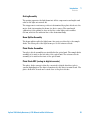
Source Lens Assembly
The source lens receives the light from the deuterium lamp and focuses it onto
the entrance slit.
Entrance Slit Assembly
The entrance slit assembly has an exchangeable slit. The standard one has a
1-mm slit. For replacement and calibration purposes to optimize the
alignment, a slit with a hole is needed.
Agilent 1260 Infinity Quaternary LC VL Manual and Quick Reference
33
1
Introduction
Detector
Filter Assembly
The filter assembly is electromechanically actuated. During wavelength
calibrations it moves into the light path.
8jid[[;^aiZgeajh=dab^jbDm^YZ;^aiZg
H]jiiZg
8jid[[;^aiZg
Figure 17
Filter Assemby
The filter assembly has two filters installed and is processor-controlled.
OPEN
nothing in light path at λ < 370 nm
CUTOFF
cut off filter in light path at λ > 370 nm
HOLMIUM holmium oxide filter for wavelength check
SHUTTER
for measurement of dark current of photo
diodes
A photo sensor determines the correct position.
Mirror Assemblies M1 and M2
The instrument contains two spherical mirrors (M1 and M2). The beam
adjustable is vertically and horizontally. Both mirrors are identical.
34
Agilent 1260 Infinity Quaternary LC VL Manual and Quick Reference
Introduction
Detector
1
Grating Assembly
The grating separates the light beam into all its component wavelengths and
reflects the light onto mirror #2.
The stepper motor reference position is determined by a plate fitted onto the
motor shaft, interrupting the beam of a photo sensor. The wavelength
calibration of the grating is done at the zero order light position and at
656 nm, which is the emission line of the deuterium lamp.
Beam Splitter Assembly
The beam splitter splits the light beam. One part goes directly to the sample
diode. The other part of the light beam goes to the reference diode.
Photo Diodes Assemblies
Two photo diode assemblies are installed in the optical unit. The sample diode
assembly is located on the left side of the optical unit. The reference diode
assembly is located in the front of the optical unit.
Photo Diode ADC (analog-to-digital converter)
The photo diode current is directly converted to digital data direct photo
current digitalization. The data is transferred to the detector main board . The
photo diode ADC boards are located close to the photo diodes.
Agilent 1260 Infinity Quaternary LC VL Manual and Quick Reference
35
1
36
Introduction
Detector
Agilent 1260 Infinity Quaternary LC VL Manual and Quick Reference
Agilent 1260 Infinity Quaternary LC VL Manual and Quick Reference
2
Specifications
Physical Specifications
38
Performance Specifications 40
Specification Conditions 47
This chapter provides information about specifications for the LC system.
Agilent Technologies
37
2
Specifications
Physical Specifications
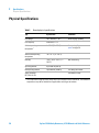
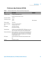
Physical Specifications
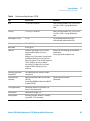
Table 2
General physical specifications
Type
Specification
Comments
Line voltage
100 – 240 VAC, ± 10 %
Wide-ranging capability
Line frequency
50 or 60 Hz, ± 5 %
Ambient operating
temperature1
4 – 55 °C (32 – 131 °F)
Ambient non-operating
temperature
-40 – 70 °C (-4 – 158 °F)
Humidity
< 95 %, at 25 – 40 °C (77 –
104 °F)
Operating altitude
Up to 2000 m (6562 ft)
Non-operating altitude
Up to 4600 m (15092 ft)
Safety standards:
IEC, CSA, UL, EN
1
38
See warning “Hot rear
panel” on page 39
Non condensing
For storing the module
For indoor use only.
This temperature range represents the technical specifications for this instrument. The mentioned
temperatures may not be suitable for all applications and all types of solvents.
Agilent 1260 Infinity Quaternary LC VL Manual and Quick Reference
Specifications
Physical Specifications
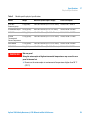
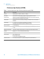
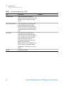
Table 3
2
Module specific physical specifications
Module
Weight
Dimension (width x depth x height)
Power consumption
G1311B/C
Quaternary pump
11 kg (24 lbs)
140 x 345 x 435 mm (5.5 x 13.5 x 17 inches)
180 VA, 55 W / 188 BTU
G1329B Autosampler
14.2 kg (32 lbs)
200 x 345 x 435 mm (8 x 13.5 x 17 inches)
300 VA, 200 W / 683 BTU
G1330B Thermostat
20.7 kg (46 lbs)
140 x 345 x 435 mm (5.5 x 13.5 x 17 inches)
260 VA, 210 W / 717 BTU
G1316B
11.2 kg (25 lbs)
Thermostatted
Column Compartment
140 x 345 x 435 mm (5.5 x 13.5 x 17 inches)
320 VA, 150 W / 512 BTU
G4212B DAD
11.5 kg (26 lbs)
140 x 345 x 435 mm (5.5 x 13.5 x 17 inches)
160 VA, 130 W / 444 BTU
G1314F VWD
11 kg (24 lbs)
140 x 345 x 435 mm (5.5 x 13.5 x 17 inches)
220 VA, 85 W / 290 BTU
WA R N I N G
Hot rear panel
Using the autosampler at high environmental temperatures may cause the rear
panel to become hot.
➔ Do not use the autosampler at environmental temperatures higher than 50 °C
(122 °F)
Agilent 1260 Infinity Quaternary LC VL Manual and Quick Reference
39
2
Specifications
Performance Specifications
Performance Specifications
Performance Specifications (G1311C)
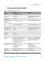
Table 4
Performance Specification Agilent 1260 Infinity Quaternary Pump VL (G1311C)
Type
Specification
Hydraulic system
Dual piston in series pump with proprietary servo-controlled variable stroke drive,
floating pistons
Setable flow range
0.001 – 10 mL/min, in 0.001 mL/min increments
Flow range
0.2 – 10.0 mL/min
Flow precision
≤0.07 % RSD, or ≤ 0.02 min SD whatever is greater, based on retention time at constant
room temperature
Flow accuracy
± 1 % or 10 µL/min whatever is greater, pumping degassed H2O at 10 MPa
Pressure
Operating range 0 – 40 MPa (0 – 400 bar, 0 – 5880 psi) up to 5 mL/min
Operating range 0 – 20 MPa (0 – 200 bar, 0 – 2950 psi) up to 10 mL/min
Pressure pulsation
< 2 % amplitude (typically < 1.0 %), or < 3 bar at 1 mL/min isopropanol, at all pressures
> 10 bar (147 psi)
Compressibility compensation
User-selectable, based on mobile phase compressibility
Recommended pH range
1.0 – 12.5, solvents with pH < 2.3 should not contain acids which attack stainless steel
Gradient formation
Low pressure quaternary mixing/gradient capability using proprietary high-speed
proportioning valve
Delay volume
600 – 900 µL, dependent on back pressure
Composition range
0 – 95 % or 5 – 100 %, user selectable
Composition precision
< 0.2 % RSD, at 0.2 and 1 mL/min
Control and data evaluation
Agilent control software
Analog output
For pressure monitoring, 2 mV/bar, one output
Communications
Controller-area network (CAN), RS-232C, APG Remote: ready, start, stop and
shut-down signals, LAN optional
40
Agilent 1260 Infinity Quaternary LC VL Manual and Quick Reference
Specifications
Performance Specifications
2
Performance Specifications (G1316A)
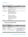
Table 5
Performance Specifications Thermostatted Column Compartment
Type
Specification
Temperature range
10 degrees below ambient to 80 °C
Comments
up to 80 °C: flow rates up to 5 mL/min
Temperature stability
± 0.15 °C
Temperature accuracy
± 0.8 °C
± 0.5 °C
Column capacity
Three 30 cm
Warm-up/cool-down
time
5 minutes from ambient to 40 °C
10 minutes from 40 – 20 °C
Dead volume
3 µL left heat exchanger
6 µL right heat exchanger
Communications
Controller-area network (CAN), RS-232C, APG Remote: ready, start,
stop and shut-down signals, LAN via other 1260 Infinity module
With calibration
Safety and maintenance Extensive diagnostics, error detection and display (through Instant
Pilot and Agilent data system), leak detection, safe leak handling,
leak output signal for shutdown of pumping system. Low voltages
in major maintenance areas.
GLP features
Column-identification module for GLP documentation of column
type.
Housing
All materials recyclable
Agilent 1260 Infinity Quaternary LC VL Manual and Quick Reference
41
2
Specifications
Performance Specifications
Performance Specifications (G1329B)
Table 6
Performance Specifications Agilent 1260 Infinity Standard Autosampler (G1329B)
Type
Specification
Pressure
Operating range 0 - 60 MPa (0 - 600 bar, 0 - 8850 psi)
GLP features
Early maintenance feedback (EMF), electronic records of maintenance and errors
Communications
Controller-area network (CAN). GPIB (IEEE-448), RS232C, APG-remote standard, optional four
external contact closures and BCD vial number output
Safety features
Leak detection and safe leak handling, low voltages in maintenance areas, error detection
and display
Injection range
0.1 - 100 µL in 0.1 µL increments (recommended 1 µL increments)
Up to 1500 µL with multiple draw (hardware modification required)
Replicate injections
1 – 99 from one vial
Precision
Typically < 0.25 % RSD of peak areas from 5 - 100 µL, Typically < 1 % RSD of peak areas from
1 - 5 µL,
Minimum sample volume
1 µL from 5 µL sample in 100 µL microvial, or 1 µL from 10 µL sample in 300 µL microvial
Carryover
Typically < 0.1 %, < 0.05 % with external needle cleaning
Sample viscosity range
0.2 – 50 cp
Sample capacity
100 × 2 mL vials in 1 tray
40 × 2 mL vials in ½ tray
15 × 6 mL vials in ½ tray (Agilent vials only)
Injection cycle time
50 s for draw speed 200 µL/min, ejection speed 200 µL/min, injection volume 5 µL
42
Agilent 1260 Infinity Quaternary LC VL Manual and Quick Reference
Specifications
Performance Specifications
2
Performance Specifications (G4212B)
Table 7
Performance Specifications G4212B
Type
Specification
Detection type
1024-element photodiode array
Light source
Deuterium lamp
Wavelength range
190 – 640 nm
Short term noise (ASTM)
Single and
Multi-Wavelength
< ± 3 × 10⁻⁶ AU at 230 nm/4 nm
see "Specification Conditions" below
Drift
< 0.5 × 10⁻³ AU/hr at 230 nm
see "Specification Conditions" below
Linear absorbance range
> 2.0 AU (5 %) at 265 nm
see "Specification Conditions" below
Wavelength accuracy
± 1 nm
After recalibration with deuterium lines
Wavelength bunching
2 – 400 nm
Programmable in steps of 1 nm
Slit width
G4212B: 4 nm
Fixed slit
Diode width
~ 0.5 nm
Signal data rate
80 Hz (G4212B)
Spectra Data rate
80 Hz (G4212B)
Flow cells
Max-Light Cartridge Cell (10 mm, V(σ) 1.0 µl),
60 bar (870 psi) pressure maximum
Max-Light Cartridge Cell (60 mm), V(σ) 4.0 µL),
60 bar (870 psi) pressure maximum
Max-Light Cartridge Test Cell
pH range 1.0 —12.5 (solvent dependent)
Cartridge type, equipped with RFID tags
that holds cell typical information.
Data System
1 Agilent ChemStation for LC
2 EZChrom Elite
3 MassHunter
For G4212B:
1 B.04.02 DSP3 or above
2 3.3.2 SP2 or above
3 B.04.00 and B.03.01 SP2 or above
Local Control
Agilent Instant Pilot (G4208A)
B.02.11 or above
Test and diagnostic
software
Agilent LabAdvisor
B.01.03 SP4 or above
Control and data evaluation
Agilent 1260 Infinity Quaternary LC VL Manual and Quick Reference
Comments
Equipped with RFID tag that holds lamp
typical information.
43
2
Specifications
Performance Specifications
Table 7
Performance Specifications G4212B
Type
Specification
Comments
Analog outputs
Recorder/integrator: 100 mV or 1 V, output range
0.001 – 2 AU, one output
Communications
Controller-area network (CAN), RS-232C, APG
Remote: ready, start, stop and shut-down
signals, LAN
Safety and maintenance
Extensive diagnostics, error detection and
display (through control module and
ChemStation), leak detection, safe leak handling,
leak output signal for shutdown of pumping
system. Low voltages in major maintenance
areas.
GLP features
Early maintenance feedback (EMF) for
continuous tracking of instrument usage in
terms of lamp burn time with user-setable limits
and feedback messages. Electronic records of
maintenance and errors. Verification of
wavelength accuracy with the emission lines of
the deuterium lamp.
Housing
All materials recyclable.
Performance Specifications (G1314F)
Table 8
Performance Specifications G1314F
Type
Specification
Detection type
Double-beam photometer
Light source
Deuterium lamp
Wavelength range
190 – 600 nm
The UV-lamp is equipped with RFID tag that
holds lamp typical information.
Short term noise
± 0.25·10-5 AU at 230 nm (G1314F)
Under specified condtions. See “Specification
Conditions (VWD)” on page 48 below the
table.
44
Comments
Agilent 1260 Infinity Quaternary LC VL Manual and Quick Reference
Specifications
Performance Specifications
Table 8
2
Performance Specifications G1314F
Type
Specification
Comments
Drift
< 1·10-4 AU/h at 230 nm
Under specified condtions. See “Specification
Conditions (VWD)” on page 48 below the
table.
Linearity
> 2.5 AU (5 %) at 265 nm
Under specified condtions. See “Specification
Conditions (VWD)” on page 48 below the
table.
Wavelength accuracy
± 1 nm
Self-calibration with deuterium lines,
verification with holmium oxide filter
Maximum sampling rate
80 Hz (G1314F)
Band width
6.5 nm typical
Flow cells
Standard: 14 µL volume, 10 mm cell path
length and 40 bar (588 psi) pressure
maximum
High pressure: 14 µL volume, cell path length
and 400 bar (5880 psi) pressure maximum
Micro: 2 µL volume, 3 mm cell path length and
120 bar (1760 psi) pressure maximum
Semi-micro: 5 µL volume, 6 mm cell path
length and 40 bar (588 psi) pressure
maximum
Electronic Temperature
Control (ETC)
For improved baseline stability in instable
environment.
Control and data
evaluation
Agilent ChemStation B.04.02 SP2 or above
(G1314F)
Instant Pilot (G4208A) with firmware B.02.11
or above (G1314F)
Time programmable
Wavelength, Reference and Sample scan,
balance, steps,lamp on/off
Spectral tools
Stop-flow wavelength scan
Analog outputs
Recorder/integrator: 100 mV or 1 V, output
range 0.001 – 2 AU, one output
All flow cells have RFID tags for unambitious
identification.
Can be repaired on component level
Control and data evaluation
Control only
Agilent 1260 Infinity Quaternary LC VL Manual and Quick Reference
45
2
Specifications
Performance Specifications
Table 8
Performance Specifications G1314F
Type
Specification
Communications
LAN card integrated on main board,
Controller-area network (CAN), RS-232C, APG
Remote: ready, start, stop and shut-down
signals
Safety and maintenance
Extensive diagnostics, error detection and
display (through Instant Pilot and Data
System), leak detection, safe leak handling,
leak output signal for shutdown of pumping
system. Low voltages in major maintenance
areas.
GLP features
Early maintenance feedback (EMF) for
continuous tracking of instrument usage in
terms of lamp burn time with user-settable
limits and feedback messages. Electronic
records of maintenance and errors.
Verification of wavelength accuracy with
built-in holmium oxide filter.
RFID for electronics records of flow cell and
UV lamp conditions (path length, volume,
product number, serial number, test passed,
usage)
Housing
All materials recyclable.
46
Comments
Agilent 1260 Infinity Quaternary LC VL Manual and Quick Reference
2
Specifications
Performance Specifications
Specification Conditions
Specification Conditions (DAD)
ASTM: “Standard Practice for Variable Wavelength Photometric Detectors
Used in Liquid Chromatography”.
Reference conditions:
• Wavelength: 230 nm/4 nm with Reference Wavelength 360 nm/100 nm,
Slitwidth 4 nm, TC 2 s, (or with RT = 2.2 * TC), ASTM
• Max-Light Cartridge Cell (10 mm, V(σ) 1.0 µl) with flow of 0.5 ml/min LC
grade water or Max-Light Cartridge Test Cell
Linearity:
Linearity is measured with caffeine at 265 nm/4 nm with slit width 4 nm and
TC 1 s (or with RT 2 s) with Max-Light Cartridge Cell (10 mm, V(σ) 1 µl) >
2.0 AU (5 %) [ typical 2.5 AU (5 %) ] .
NOTE
The specifications are based on the standard RFID tag lamp (5190-0917) and may be not
achieved when other lamp types or aged lamps are used.
ASTM drift tests require a temperature change below 2 °C/hour (3.6 F/hour)
over one hour period. Our published drift specification is based on these
conditions. Larger ambient temperature changes will result in larger drift.
Better drift performance depends on better control of the temperature
fluctuations. To realize the highest performance, minimize the frequency and
the amplitude of the temperature changes to below 1 °C/hour (1.8 F/hour).
Turbulences around one minute or less can be ignored.
Performance tests should be done with a completely warmed up optical unit (>
two hours). ASTM measurements require that the detector should be turned
on at least 24 h before start of testing.
Agilent 1260 Infinity Quaternary LC VL Manual and Quick Reference
47
2
Specifications
Performance Specifications
Specification Conditions (VWD)
ASTM: “Standard Practice for Variable Wavelength Photometric Detectors
Used in Liquid Chromatography”.
Reference conditions: Standard flow cell, path length 10 mm, flow 1 mL/min
LC-grade methanol.
Noise:
± 0.15·10-5 AU (G1314E/D), ± 0.25·10-5 AU (G1314F) at 230 nm, TC 2 s
RT = 2.2 * TC
Linearity:
Linearity is measured with caffeine at 265 nm.
NOTE
The specification are based on the the standard RFID tag lamp (G1314-60101) and may be
not achieved when other lamp types or aged lamps are used.
ASTM drift tests require a temperature change below 2°C/hour (3.6°F/hour)
over one hour period. Our published drift specification is based on these
conditions. Larger ambient temperature changes will result in larger drift.
Better drift performance depends on better control of the temperature
fluctuations. To realize the highest performance, minimize the frequency and
the amplitude of the temperature changes to below 1°C/hour (1.8°F/hour).
Turbulences around one minute or less can be ignored.
Performance tests should be done with a completely warmed up optical unit (>
one hour). ASTM measurements require that the detector should be turned on
at least 24 hours before start of testing.
Time Constant versus Response Time
According to ASTM E1657-98 „Standard Practice of Testing
Variable-Wavelength Photometric Detectors Used in Liquid Chromatography”
the time constant is converted to response time by multiplying by the factor
2.2.
48
Agilent 1260 Infinity Quaternary LC VL Manual and Quick Reference
Agilent 1260 Infinity Quaternary LC VL Manual and Quick Reference
3
Optimization of the Agilent 1260 Infinity
Quaternary LC VL
Optimizing the Pump 50
Operational Hints for the Vacuum Degasser 50
Operational Hints for the Multi Channel Gradient Valve (MCGV)
When to Use the Seal Wash Option 51
Choosing the Right Pump Seals 52
Optimize the Compressibility Compensation Setting 52
Optimizing the Autosampler 54
Optimization for Lowest Carry-over 54
Fast Injection Cycle and Low Delay Volume
Precise Injection Volume 58
Choice of Rotor Seal 60
50
57
Optimizing the Thermostatted Column Compartment
61
Optimizing the Detector Regarding to the System 62
Delay Volume and Extra-Column Volume 62
Optimizing Detection with DAD 63
Introduction 63
Optimization Overview 64
Optimizing for Sensitivity, Selectivity, Linearity and Dispersion
Optimizing Selectivity 73
Warm up of the Detector 76
65
Optimizing Detection with VWD 78
Optimizing the Detector Performance 78
Match the Flow Cell to the Column 78
Set the Detector Parameters (VWD) 81
This chapter considers how to apply the theory and use the features of the LC
system to develop optimized separations.
Agilent Technologies
49
3
Optimization of the Agilent 1260 Infinity Quaternary LC VL
Optimizing the Pump
Optimizing the Pump
Operational Hints for the Vacuum Degasser
Operational Hints for the Vacuum Degasser
If you are using the vacuum degasser for the first time, if the vacuum degasser
was switched off for any length of time (for example, overnight), or if the
vacuum degasser lines are empty, you should prime the vacuum degasser
before running an analysis.
The vacuum degasser can be primed either by drawing solvent through the
degasser with a syringe or by pumping with the quaternary pump.
Priming the degasser with a syringe is recommended, when:
• vacuum degasser is used for the first time, or vacuum tubes are empty, or
• changing to solvents that are immiscible with the solvent currently in the
vacuum tubes.
Priming the vacuum degasser by using the quaternary pump at high flow rate
is recommended, when:
• quaternary pump was turned off for a length of time (for example, during
night) and volatile solvent mixtures are used, or
• solvents have been changed.
For more information see the Service Manual for the Agilent 1200 Series
vacuum degasser.
Operational Hints for the Multi Channel Gradient Valve (MCGV)
In a mixture of salt solutions and organic solvent the salt solution might be
well dissolved in the organic solvent without showing precipitations. However
in the mixing point of the gradient valve, at the boundary between the two
solvents, micro precipitation is possible. Gravity forces the salt particles to fall
down. Normally the A channel of the valve is used for the aqueous/salt
solution and the B channel of the pump is used for the organic solvent. If used
50
Agilent 1260 Infinity Quaternary LC VL Manual and Quick Reference
3
Optimization of the Agilent 1260 Infinity Quaternary LC VL
Optimizing the Pump
in this configuration the salt will fall back into the salt solution and will be
dissolved. When using the pump in a different configuration (e.g., D - salt
solution, A - organic solvent) the salt can fall into the port of the organic
solvent and may lead to performance problems.
NOTE
When using salt solutions and organic solvents it is recommended to connect the salt
solution to one of the bottom ports of the MCGV and the organic solvent to one of the upper
gradient valve ports. It is best to have the organic channel directly above the salt solution
channel. Regular flushing with water of all MCGV channels is recommended to remove all
possible salt deposits in the valve ports.
When to Use the Seal Wash Option
Highly concentrated buffer solutions will reduce the lifetime of the seals and
pistons in your pump. The seal wash option allows to maintain the seal
lifetime by flushing the back side of the seal with a wash solvent.
The seal wash option is strongly recommended when buffer concentrations of
0.1 M or higher will be used for long time periods in the pump.
The active seal wash upgrade can be ordered as G1398A.
The seal wash option comprises a support ring, secondary seal, gasket and
seal holder for both piston sides. A wash bottle filled with water /isopropanol
(90/10) is placed above the pump in the solvent cabinet and the peristaltic
pump moves a flow through the pump head removing all possible buffer
crystals from the back of the pump seal.
NOTE
Running dry is the worst case for a wash seal and drastically reduces its lifetime.
The seal will build up sticky layers on the surface of the piston. These sticky layers will also
reduce the lifetime of the pump seal. Therefore the tubes of the wash option should always
be filled with solvent to prolong the lifetime of the wash seal. Always use a mixture of LC
grade water (90 %) and isopropanol (10 %) as wash solvent. This mixture prevents growth
of algae or bacteria in the wash bottle and reduces the surface tension of the water.
Agilent 1260 Infinity Quaternary LC VL Manual and Quick Reference
51
3
Optimization of the Agilent 1260 Infinity Quaternary LC VL
Optimizing the Pump
Choosing the Right Pump Seals
The standard seal for the pump can be used for most applications. However
applications that use normal phase solvents (for example, hexane) are not
suited for the standard seal and require a different seal when used for a longer
time in the pump.
For applications that use normal phase solvents (for example, hexane) we
recommend using polyethylene pump seals (PE seals (pack of 2) (p/n
0905-1420)) and Wash Seal PE (p/n 0905-1718). These seals have less
abrasion compared to the standard seals.
NOTE
Polyethylene seals have a limited pressure range of 0 – 200 bar. When used above 200 bar
their lifetime is reduced significantly. DO NOT apply the seal wear-in procedure performed
with new standard seals at 400 bar.
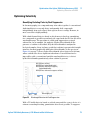
Optimize the Compressibility Compensation Setting
The compressibility compensation default setting is 100 × 10-6 /bar for the
pump. This setting represents an average value. Under normal conditions the
default setting reduces the pressure pulsation to values (below 1% of system
pressure) that will be sufficient for most applications and for all gradient
analyses. For applications using sensitive detectors, the compressibility
settings can be optimized by using the values for the various solvents
described in Table 9 on page 53. If the solvent in use is not listed in the
compressibility tables, when using isocratic mixtures of solvents and if the
default settings are not sufficient for your application the following procedure
can be used to optimize the compressibility settings.
NOTE
When using mixtures of solvents it is not possible to calculate the compressibility of the
mixture by interpolating the compressibility values of the pure solvents used in that mixture
or by applying any other calculation. In these cases the following empirical procedure has
to be applied to optimize your compressibility setting.
1 Start the pump with the required flow rate.
2 Before starting the optimization procedure, the flow must be stable. Check
the tightness of the system with the pressure test.
52
Agilent 1260 Infinity Quaternary LC VL Manual and Quick Reference
3
Optimization of the Agilent 1260 Infinity Quaternary LC VL
Optimizing the Pump
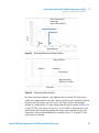
3 Your pump must be connected to a data system or Instant Pilot with which
the pressure and %-ripple can be monitored, otherwhise connect a signal
cable between the pressure output of the pump and a recording device (for
example, 339X integrator) and set parameters.
Zero 50 %
Att 2^3 Chart
Speed 10 cm/min
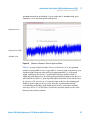
4 Start the recording device with the plot mode.
5 Starting with a compressibility setting of 10 × 10-6 /bar increase the value
in steps of 10. Re-zero the integrator as required. The compressibility
compensation setting that generates the smallest pressure ripple is the
optimum value for your solvent composition.
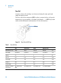
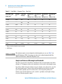
Table 9
Solvent Compressibility
Solvent (pure)
Compressibility (10-6/bar)
Acetone
126
Acetonitrile
115
Benzene
95
Carbon tetrachloride
110
Chloroform
100
Cyclohexane
118
Ethanol
114
Ethyl acetate
104
Heptane
120
Hexane
150
Isobutanol
100
Isopropanol
100
Methanol
120
1-Propanol
100
Toluene
87
Water
46
Agilent 1260 Infinity Quaternary LC VL Manual and Quick Reference
53
3
Optimization of the Agilent 1260 Infinity Quaternary LC VL
Optimizing the Autosampler
Optimizing the Autosampler
Optimization for Lowest Carry-over
Several parts of an injection system can contribute to carry-over:
• needle outside
• needle inside
• needle seat
• sample loop
• seat capillary
• injection valve
The autosampler continuous flow-through design ensures that sample loop,
needle inside, seat capillary, and the mainpass of the injection valve is always
in the flow line. These parts are continuously flushed during an isocratic and
also during a gradient analysis. The residual amount of sample remaining on
the outside of the needle after injection may contribute to carry-over in some
instances. When using small injection volumes or when injecting samples of
low concentration immediately after samples of high concentration, carry-over
may become noticeable. Using the automated needle wash enables the
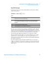
carry-over to be minimized and prevents also contamination of the needle
seat.
Using the Automated Needle Wash
The automated needle wash can be programmed either as “injection with
needle wash” or the needle wash can be included into the injector program.
When the automated needle wash is used, the needle is moved into a wash vial
after the sample is drawn. By washing the needle after drawing a sample, the
sample is removed from the surface of the needle immediately.
54
Agilent 1260 Infinity Quaternary LC VL Manual and Quick Reference
Optimization of the Agilent 1260 Infinity Quaternary LC VL
Optimizing the Autosampler
3
Uncapped Wash Vial
For best results, the wash vial should contain solvent in which the sample
components are soluble, and the vial should not be capped. If the wash vial is
capped, small amounts of sample remain on the surface of the septum, which
may be carried on the needle to the next sample.
Injector Program with Needle Wash
The injector program includes the command NEEDLE WASH. When this
command is included in the injector program, the needle is lowered once into
the specified wash vial before injection.
For example:
1 DRAW 5 µl
2 NEEDLE WASH vial 7
3 INJECT
Line 1 draws 5 µl from the current sample vial. Line 2 moves the needle to vial
7. Line 3 injects the sample (valve switches to main pass).
Using an Injector Program
The process is based on a program that switches the bypass grove of the
injection valve into the flow line for cleaning. This switching event is
performed at the end of the equilibration time to ensure that the bypass grove
is filled with the start concentration of the mobile phase. Otherwise the
separation could be influenced, especially if microbore columns are used.
Agilent 1260 Infinity Quaternary LC VL Manual and Quick Reference
55
3
Optimization of the Agilent 1260 Infinity Quaternary LC VL
Optimizing the Autosampler
For example:
Outside wash of needle in vial 7 before injection
Injector program:
Draw x.x (y) µl from sample
NEEDLE WASH vial 7
Inject
Wait (equilibration time - see text above)
Valve bypass
Wait 0.2 min
Valve mainpass
Valve bypass
Valve mainpass
NOTE
Overlapped injection together with additional injection valve switching is not possible.
General Recommendation to Lowest Carry-over
• For samples where needle outside cannot be cleaned sufficiently with water
or alcohol use wash vials with an appropriate solvent. Using an injector
program and several wash vials can be used for cleaning.
In case the needle seat has got contaminated and carry-over is significantly
higher than expected, the following procedure can be used to clean the needle
seat:
• Go to MORE INJECTOR and set needle to home position.
• Pipette an appropriate solvent on to the needle seat. The solvent should be
able to dissolve the contamination. If this is not known use 2 or 3 solvents
of different polarity. Use several milliliters to clean the seat.
• Clean the needle seat with a tissue and remove all liquid from it.
• RESET the injector.
56
Agilent 1260 Infinity Quaternary LC VL Manual and Quick Reference
3
Optimization of the Agilent 1260 Infinity Quaternary LC VL
Optimizing the Autosampler
Fast Injection Cycle and Low Delay Volume
Short injection cycle times for high sample througput is one of the most
important requirements in analytical laboratories. In order to shorten cycle
times, you can:
• shorten the column length
• use high flow rates
• apply a steep gradient
Having optimized these parameters, further reduction of cycle times can be
obtained using the overlapped injection mode.
Overlapped Injection Mode
In this process, as soon as the sample has reached the column, the injection
valve is switched back to bypass and the next injection cycle starts but waits
with switching to mainpass until the actual run is finished. You gain the
sample preparation time when using this process.
Switching the valve into the bypass position reduces the system delay volume,
the mobile phase is directed to the column without passing sample loop,
needle and needle seat capillary. This can help to have faster cycle times
especially if low flow rates have to be used like it is mandatory in narrow bore
and micro bore HPLC.
NOTE
Having the valve in bypass position can increase the carry-over in the system.
The injection cycle times also depend on the injection volume. In identically
standard condition, injecting 100 µl instead of 1 µl, increase the injection time
by approximately 8 sec. In this case and if the viscosity of the sample allows it,
the draw and eject speed of the injection system has to be increased.
NOTE
For the last injection of the sequence with overlapped injections it has to be considered
that for this run the injection valve is not switched as for the previous runs and
consequently the injector delay volume is not bypassed. This means the retention times are
prolonged for the last run. Especially at low flow rates this can lead to retention time
changes which are too big for the actual calibration table. To overcome this it is
recommended to add an additional “blank” injection as last injection to the sequence.
Agilent 1260 Infinity Quaternary LC VL Manual and Quick Reference
57
3
Optimization of the Agilent 1260 Infinity Quaternary LC VL
Optimizing the Autosampler
General Recommendations for Fast Injection Cycle Times
As described in this section, the first step to provide short cycle times are
optimizing the chromatographic conditions. If this is done the autosampler
parameter should be set to:
• Overlapped injection mode
• Increase of draw and eject speed for large injection volumes
• Add at last run a blank, if overlapped injection is used
To reduce the injection time, the detector balance has to be set to OFF.
Precise Injection Volume
Injection Volumes Less Than 2 µL
When the injection valve switches to the BYPASS position, the mobile phase in
the sample loop is depressurized. When the syringe begins drawing sample,
the pressureof the mobile phase is decreased further. If the mobile phase is
not degassed adequately, small gas bubbles may form in the sample loop
during the injection sequence. When using injection volumes < 2 µL, these gas
bubbles may affect the injection-volume precision. For best injection-volume
precision with injection volumes < 2 µL, use of an Agilent 1260 Infinity
degasser is recommended to ensure the mobile phase is adequately degassed.
Also, using the automated needle wash (see “Optimization for Lowest
Carry-over” on page 54) between injections reduces carry-over to a minimum,
further improving the injection volume precision.
Draw and Eject Speed
Draw Speed
The speed at which the metering unit draws sample out of the vial may have an
influence on the injection volume precision when using viscous samples. If the
draw speed is too high, air bubbles may form in the sample plug, affecting
precision. The default draw speed is 200 µL/min. This speed is suitable for the
majority of applications, however, when using viscous samples, set the draw
speed to lower speed for optimum results. A DRAW statement in an injector
58
Agilent 1260 Infinity Quaternary LC VL Manual and Quick Reference
Optimization of the Agilent 1260 Infinity Quaternary LC VL
Optimizing the Autosampler
3
program also uses the draw speed setting which is configured for the
autosampler.
Eject Speed
The default eject speed setting is 200 µL/min. When using large injection
volumes, setting the eject speed to a higher value speeds up the injection cycle
by shortening the time the metering unit requires to eject solvent at the
beginning of the injection cycle (when the plunger returns to the home
position).
An EJECT statement in an injector program also uses the eject speed setting
which is configured for the autosampler. A faster eject speed shortens the time
required to run the injector program. When using viscous samples, a high eject
speed should be avoided.
Agilent 1260 Infinity Quaternary LC VL Manual and Quick Reference
59
3
Optimization of the Agilent 1260 Infinity Quaternary LC VL
Optimizing the Autosampler
Choice of Rotor Seal
Vespel™ Seal (for standard valves only)
The standard seal has sealing material made of Vespel. Vespel is suitable for
applications using mobile phases within the pH range of 2.3 to 9.5, which is
suitable for the majority of applications. However, for applications using
mobile phases with pH below 2.3 or above 9.5, the Vespel seal may degrade
faster, leading to reduced seal lifetime.
Tefzel™ Seal (for standard valves only)
For mobile phases with pH below 2.3 or above 9.5, or for conditions where the
lifetime of the Vespel seal is drastically reduced, a seal made of Tefzel is
available. Tefzel is more resistant than Vespel to extremes of pH, however, is a
slightly softer material. Under normal conditions, the expected lifetime of the
Tefzel seal is shorter than the Vespel seal, however, Tefzel may have the longer
lifetime under more extreme mobile phase conditions.
PEEK Seal (for preparative injection valve only)
The preparative injection valve has a sealing material made of PEEK. This
material has high chemical resistance and versatility. It is suitable for
application using mobile phases within a pH between 1 and 14.
NOTE
60
Strong oxidizing acids such as concentrated nitric and sulfuric acids are not compatible
with PEEK.
Agilent 1260 Infinity Quaternary LC VL Manual and Quick Reference
3
Optimization of the Agilent 1260 Infinity Quaternary LC VL
Optimizing the Thermostatted Column Compartment
Optimizing the Thermostatted Column Compartment
For best performance results of the column compartment:
• Use short connection capillaries and place them close to the heat
exchanger. This will reduce heat dissipation and external band-broadening.
• Use the left heat exchanger for small volume columns, for example, 2 –
3 mm i.d. columns at flow rates of less than 200 µL/min.
• For even lower band-broadening, the heat exchanger can be by-passed and
the column is placed well between the heat exchanger fins.
• Keep the left and right heat exchanger temperature the same unless you do
specific applications.
• Assure that the front cover is always closed.
Agilent 1260 Infinity Quaternary LC VL Manual and Quick Reference
61
3
Optimization of the Agilent 1260 Infinity Quaternary LC VL
Optimizing the Detector Regarding to the System
Optimizing the Detector Regarding to the System
Delay Volume and Extra-Column Volume
The delay volume is defined as the system volume between the point of mixing
in the pump and the top of the column.
The extra-column volume is defined as the volume between the injection point
and the detection point, excluding the volume in the column.
Extra-Column Volume
Extra-column volume is a source of peak dispersion that will reduce the
resolution of the separation and so should be minimized. Smaller diameter
columns require proportionally smaller extra-column volumes to keep peak
dispersion at a minimum.
In a liquid chromatograph the extra-column volume will depend on the
connection tubing between the autosampler, column and detector; and on the
volume of the flow cell in the detector. The extra-column volume is minimized
with the Agilent 1290 Infinity/Agilent 1260 Infinity LC System due to the
narrow-bore (0.12 mm i.d.) tubing, the low-volume heat exchangers in the
column compartment and the Max-Light cartridge cell in the detector.
62
Agilent 1260 Infinity Quaternary LC VL Manual and Quick Reference
Optimization of the Agilent 1260 Infinity Quaternary LC VL
Optimizing Detection with DAD
3
Optimizing Detection with DAD
Introduction
The detector has a variety of parameters that can be used to optimize
performance. Depending on whether signal or spectral data need to be
optimized, different settings are recommended. The following sections
describe optimization for:
• signal sensitivity, selectivity and linearity,
• spectral sensitivity and resolution (DAD only), and
• disk space required for storing data.
NOTE
The information in this chapter should be seen as a basic introduction to diode array
detector techniques. Some of these techniques may not be available in the instrument
software controlling the detector.
How to Get the Best Detector Performance
The information below will guide you on how to get the best detector
performance. Follow these rules as a start for new applications. It gives
rules-of-thumb for optimizing detector parameters.
Agilent 1260 Infinity Quaternary LC VL Manual and Quick Reference
63
3
Optimization of the Agilent 1260 Infinity Quaternary LC VL
Optimizing Detection with DAD
Optimization Overview
Table 10
Optimization Overview
Parameter
Impact
1 Selection of flow cell
•
peak resolution versus sensitivity
•
chromatographic resolution
•
peak resolution versus sensitivity
versus disk space
•
sensitivity versus selectivity
•
sensitivity versus linearity
•
baseline drift due to RI effects.
•
Choose flow cell according to used column, see “Choosing a Flow Cell” on
page 65.
2 Connection of flow cell
•
•
For flow rates from 0.5 ml/min connect column using the zero-dead-volume
fittings of the detector.
For small column i.d. (e.g 1 mm) the inlet capillary of the micro flow cell can
be connected directly to the column.
3 Setting the peak width (response time)
•
•
Use peak width according “Choosing a Flow Cell” on page 65 as starting
point.
Set the peak-width close to the width of a narrow peak of interest in your
chromatogram.
4 Setting wavelength and bandwidth
•
•
64
Sample wavelength:
• Never miss a peak by the use of a browser wavelength like 250 nm with
100 nm bandwidth.
• Select specific wavelength with reduced bandwidth if you need
selectivity, e.g. 250,10 nm and 360,100 nm as reference wavelength.
• Set the sample wavelength to a peak or valley in the spectrum to get
best linearity for high concentrations.
Reference wavelength:
• Select the reference wavelength with broad bandwidth (30...100 nm)
wavelength range where your analytes have little or no absorbance (e.g.
sample at 254 nm, reference at 320 nm).
Agilent 1260 Infinity Quaternary LC VL Manual and Quick Reference
Optimization of the Agilent 1260 Infinity Quaternary LC VL
Optimizing Detection with DAD
3
Choosing a Flow Cell
The Max-Light Cartridge Cell with path length 10 mm and volume (σ) 1.0 µl
covers a wide range of applications:
• all column diameter down to at least 2.1 mm ID or even less
• applications with peak dispersion (Peakwidth x flow) down to ~2 µl
[example: pw = 0.04 min at flow = 0.1 ml/min gives peak dispersion of
0.04 min x 0.1 ml/min = 0.004 ml = 4 µl]
If higher sensitivity is necessary, the Max-Light Cartridge Cell with path length
60 mm and volume (σ) 4 µL can be used. This cell enhances the detector by
lowering the limit of detection (LOD) by a factor of about 3 (depending on the
application).
Optimizing for Sensitivity, Selectivity, Linearity and Dispersion
Flow Cell Path Length
Lambert-Beer’s law shows a linear relationship between the flow cell path
length and absorbance.
where
T is the transmission, defined as the quotient of the intensity of the
transmitted light I divided by the intensity of the incident light, I0,
ε is the extinction coefficient, which is a characteristic of a given substance
under a precisely-defined set of conditions of wavelength, solvent,
temperature and other parameters,
C [mol/L] is the concentration of the absorbing species, and
d [cm] is the path length of the cell used for the measurement.
The detector can now output the signal in two forms:
1 In Absorbance divide by the path length AU/cm, that is then similar to [ε x
C]. Advantage: samples with same concentration have same peak height
also at cells with different path lengths.
Agilent 1260 Infinity Quaternary LC VL Manual and Quick Reference
65
3
Optimization of the Agilent 1260 Infinity Quaternary LC VL
Optimizing Detection with DAD
The upper limit of concentration: the linearity limit of the detector is then
seen at about 2 AU/path length, so for the 6 cm Max-Light Cartridge Cell the
linearity limit is 333 mAU/cm].
2 In AU that is equal to ε x C x d like normal done in the past: now for
recalculation to your concentration C the path length must be considered.
Therefore, flow cells with longer path lengths yield higher signals. Although
noise usually increases little with increasing path length, there is a gain in
signal-to-noise ratio.
When increasing the path length, the cell volume could increase. Depending on
the peak volume, this could cause more peak dispersion.
As a rule-of-thumb the flow cell volume should be about 1/3 of the peak
volume at half height. To determine the volume of your peaks, take the peak
width as reported in the integration results multiply it by the flow rate and
divide it by 3).
NOTE
This may result in problems when the used peak width is set to large and all peaks are
filtered accordingly.
Traditionally LC analysis with UV detectors is based on comparing
measurements with internal or external standards. To check photometric
accuracy of the Agilent detector it is necessary to have more precise
information on path lengths of the detector flow cells.
Part Number
Path Length
Cell Volume (σ)
G4213-60008
1.0 cm
1.0 µL
G4213-60007
6.0 cm
4.0 µL
Peak width (response time)
Response time describes how fast the detector signal follows a sudden change
of absorbance in the flow cell. The detector uses digital filters to adapt
response time to the width of the peaks in your chromatogram. These filters
do not affect peak area nor peak symmetry. When set correctly, such filters
reduce baseline noise significantly ( Figure 18 on page 67), but reduce peak
height only slightly. In addition, these filters reduce the data rate to allow
66
Agilent 1260 Infinity Quaternary LC VL Manual and Quick Reference
Optimization of the Agilent 1260 Infinity Quaternary LC VL
Optimizing Detection with DAD
3
optimum integration and display of your peaks and to minimize disk space
required to store chromatograms and spectra.
GZhedchZi^bZ2'h
GZhedchZi^bZ2%#%&+h
Ha^il^Yi]2)cb
Figure 18
Influence of Response Time on Signal and Noise
Table 11 on page 68 lists the filter choices of the detector. To get optimum
results, set peak width as close as possible to a narrow peak of interest in your
chromatogram. Response time will the be approximately 1/3 of the peak
width, resulting in less than 5 % peak-height reduction and less than 5 %
additional peak dispersion. Decreasing the peak width setting in the detector
will result in less than 5 % gain in peak height but baseline noise will increase
by a factor of 1.4 for a factor of 2 response-time reduction. Increasing peak
width (response time) by factor of two from the recommended setting
(over-filtering) will reduce peak height by about 20 % and reduce baseline
noise by a factor of 1.4. This gives you the best possible signal-to-noise ratio,
but may affect peak resolution.
Agilent 1260 Infinity Quaternary LC VL Manual and Quick Reference
67
3
Optimization of the Agilent 1260 Infinity Quaternary LC VL
Optimizing Detection with DAD
Table 11
Peak Width — Response Time — Data Rate
Peak width at half
height [min]1
Response
[s]
Signal data
rate [Hz]
Scan data rate
[HZ]
≤126 pts/scan
Scan data rate
[HZ]
≤251 pts/scan
Scan data rate
[HZ]
≤501 pts/scan
Scan data rate
[HZ]
>501 pts/scan
< 0.0016
0.016
1602
1602
80
40
20
> 0.0016
0.03
1602
1602
80
40
20
> 0.003
0.062
80
80
80
80
40
> 0.006
0.12
40
40
40
40
40
> 0.012
0.25
20
20
20
20
20
> 0.025
0.5
10
10
10
10
10
> 0.05
1.0
5
5
5
5
5
> 0.10
2.0
2.5
2.5
2.5
2.5
2.5
> 0.20
4.0
1.25
1.25
1.25
1.25
1.25
> 0.40
8.0
0.625
0.62
0.625
0.625
0.625
> 0.85
16.0
0.3125
0.31
0.3125
0.3125
0.3125
1
Values in the User Interface may be rounded.
2
G4212A only
NOTE
The maximum spectra scan rate depends on the data points per scan, see Table 11 on
page 68. Running at 160 Hz, the spectra scan data rate is reduced automatically if the
spectra scan data rate is more than 251 points/scan.
Sample and Reference Wavelength and Bandwidth
The detector measures absorbance simultaneously at wavelengths from 190 to
640 nm. A UV-lamp provides good sensitivity over the whole wavelength range.
If you know little about the analytes in your sample, store all spectra over the
full wavelength range. This provides full information but fills up your disk
space rather quickly. Spectra can be used to check a peak’s purity and
identity. Spectral information is also useful to optimize wavelength settings
for your chromatographic signal.
68
Agilent 1260 Infinity Quaternary LC VL Manual and Quick Reference
3
Optimization of the Agilent 1260 Infinity Quaternary LC VL
Optimizing Detection with DAD
The detector can compute and store at run time up to 8 signals with these
properties:
• sample wavelength, the center of a wavelength band with the width of
sample bandwidth (BW), and optionally
• reference wavelength, the center of a wavelength band with the width of
reference bandwidth.
The signals comprises a series of data points over time, with the average
absorbance in the sample wavelength band minus the average absorbance of
the reference wavelength band.
Signal A in the detector default method is set to sample 254.0/4, reference
360.0/100, that is, the average absorbance from 252 – 256 nm minus the
average absorbance from 310 – 410 nm. As all analytes show higher
absorbance at 252 – 256 nm than at 310 – 410 nm, this signal will show you
virtually every compound which can be detected by UV absorbance.
Many compounds show absorbance bands in the spectrum. Figure 19 on
page 70 shows the spectrum of anisic acid as an example. To optimize for
lowest possible detectable concentrations of anisic acid, set the sample
wavelength to the peak of the absorbance band (that is, 252 nm) and the
sample bandwidth to the width of the absorbance band (that is, 30 nm). A
reference of 360,100 is adequate. Anisic acid does not absorb in this range.
If you work with high concentrations, you may get better linearity above
1.5 AU by setting the sample wavelength to a valley in the spectrum, like
225 nm for anisic acid.
Agilent 1260 Infinity Quaternary LC VL Manual and Quick Reference
69
3
Optimization of the Agilent 1260 Infinity Quaternary LC VL
Optimizing Detection with DAD
6c^h^XVX^Y
hVbeaZlVkZaZc\i]'*'cb
6WhdgWVcXZb6J
GZ[ZgZcXZWVcYl^Yi]&%%cb
(%cb
WVcYl^Yi]
GZ[ZgZcXZlVkZaZc\i](+%
LVkZaZc\i]cb
Figure 19
Optimization of Wavelength Setting
A wide bandwidth has the advantage of reducing noise by averaging over a
wavelength range — compared to a 4 nm bandwidth, the baseline noise is
reduced by a factor of approximately 2.5, whereas the signal is about 75 % of a
4 nm wide band. The signal-to-noise ratio for a 30 nm bandwidth is twice that
for a 4 nm bandwidth in our example.
7VcYl^Yi]
(%cb
&'cb
)cb
Figure 20
70
Influence of Bandwidth on Signal and Noise
Agilent 1260 Infinity Quaternary LC VL Manual and Quick Reference
Optimization of the Agilent 1260 Infinity Quaternary LC VL
Optimizing Detection with DAD
3
Because the detector averages absorbance values that are calculated for each
wavelength, using a wide bandwidth does not negatively impact linearity.
The use of a reference wavelength is highly recommended to further reduce
baseline drift and wander induced by room temperature fluctuations or
refractive index changes during a gradient.
EI="E=:
EI="EGD
EI="6G<
EI="6A6
EI="6HC
An example of the reduction of baseline drifts is shown in Figure 21 on
page 71 for PTH-amino acids. Without a reference wavelength, the
chromatogram drifts downwards due to refractive index changes induced by
the gradient. This is almost completely eliminated by using a reference
wavelength. With this technique, PTH-amino acids can be quantified in the low
picomole range even in a gradient analysis.
&ebdaZVX]
LVkZaZc\i]
'+,cb
GZ[ZgZcXZ(-%cb
LVkZaZc\i]
'+,cb
CdgZ[ZgZcXZ
I^bZb^c
<gVY#/%#%'b@=ED$68C[gdb&'68Cid)*68C^c&'b^c
' )
Figure 21
Gradient Analysis of PTH-Amino Acids (1 pmol each), with and without
Reference
Agilent 1260 Infinity Quaternary LC VL Manual and Quick Reference
71
3
Optimization of the Agilent 1260 Infinity Quaternary LC VL
Optimizing Detection with DAD
Optimizing Spectral Acquisition (DAD only)
Storage of all spectra consumes a lot of disk space. It is very useful to have all
spectra available during optimization of a method or when analyzing unique
samples. However when running many samples of the same type, the large size
of data files with all spectra may become a burden. The detector provides
functions to reduce the amount of data, yet retaining the relevant spectral
information.
Range
Only the wavelength range where the compounds in your sample absorb
contains information that is useful for purity checks and library searches.
Reducing the spectrum storage range saves disk space.
Step
Most substances have broad absorbance bands. Display of spectra, peak purity
and library search works best if a spectrum contains 5 to 10 data points per
width of the absorbance bands. For anisic acid (the example used before) a
step of 4 nm would be sufficient. However a step of 2 nm gives a more optimal
display of the spectrum.
Threshold
Sets the peak detector. Only spectra from peaks higher than threshold will be
stored when a peak-controlled storage mode is selected.
Margin for Negative Absorbance
The detector adjusts its gain during balance such that the baseline may drift
slightly negative (about -100 mAU). In some special case, for example, when
gradient with absorbing solvents are used, the baseline may drift to more
negative values.
Only for such cases, increase the margin for negative absorbance to avoid
overflow of the analog-to-digital converter.
72
Agilent 1260 Infinity Quaternary LC VL Manual and Quick Reference
3
Optimization of the Agilent 1260 Infinity Quaternary LC VL
Optimizing Detection with DAD
Optimizing Selectivity
Quantifying Coeluting Peaks by Peak Suppression
In chromatography, two compounds may often elute together. A conventional
dual-signal detector can only detect and quantify both compounds
independently from each other if their spectra do not overlap. However, in
most cases this is highly unlikely.
With a dual-channel detector based on diode-array technology, quantifying
two compounds is possible even when both compounds absorb over the whole
wavelength range. The procedure is called peak suppression or signal
subtraction. As an example, the analysis of hydrochlorothiazide in the
presence of caffeine is described. If hydrochlorothiazide is analyzed in
biological samples, there is always a risk that caffeine is present which might
interfere chromatographically with hydrochlorothiazide. As the spectra in
Figure 22 on page 73 shows, hydrochlorothiazide is best detected at 222 nm,
where caffeine also shows significant absorbance. It would therefore be
impossible, with a conventional variable wavelength detector, to detect
hydrochlorothiazide quantitatively when caffeine is present.
LA&'%)cb!XV[[Z^cZ
LA''''cb!]nYgdX]adgdi]^Vo^YZ
LA('+%cb!gZ[ZgZcXZidhjeegZhh
]nYgdX]adgdi]^Vo^YZ
LA)'-'cb!gZ[ZgZcXZidhjeegZhhXV[[Z^cZ
LA(
LA&
Figure 22
LA'
LA)
LVkZaZc\i]cb
Wavelength Selection for Peak Suppression
With a UV-visible detector based on a diode array and the correct choice of a
reference wavelength setting, quantitative detection is possible. To suppress
Agilent 1260 Infinity Quaternary LC VL Manual and Quick Reference
73
3
Optimization of the Agilent 1260 Infinity Quaternary LC VL
Optimizing Detection with DAD
caffeine, the reference wavelength must be set to 282 nm. At this wavelength,
caffeine shows exactly the same absorbance as at 222 nm. When the
absorbance values are subtracted from each another, any indication of the
presence of caffeine is eliminated. In the same way, hydrochlorothiazide can
be suppressed if caffeine is to be quantified. In this case the wavelength is set
to 204 nm and the reference wavelength to 260 nm. Figure 23 on page 74
shows the chromatographic results of the peak suppression technique.
The trade-off for this procedure is a loss in sensitivity. The sample signal
decreases by the absorbance at the reference wavelength relative to the signal
wavelength. Sensitivity may be decreased by as much as 10–30 %.
=nYgdX]adgdi]^Vo^YZ
VcYXV[[Z^cZ
LVkZaZc\i]'%)cb
CdgZ[ZgZcXZ
=nYgdX]adgdi]^Vo^YZ
VcYXV[[Z^cZ
LVkZaZc\i]'''cb
CdgZ[ZgZcXZ
=nYgdX]adgdi]^Vo^YZh
jeegZhhZY
LVkZaZc\i]'%)cb
GZ[ZgZcXZ'+%cb
8V[[Z^cZhjeegZhhZY
I^bZb^c
Figure 23
LVkZaZc\i]'''cb
GZ[ZgZcXZ'-'cb
I^bZb^c
Peak Suppression Using Reference Wavelength
Ratio Qualifiers for Selective Detection of Compound Classes
Ratio qualifiers can be used where, in a complex sample, only one particular
class needs to be analyzed — a parent drug and its metabolites in a biological
sample, for example. Another example is the selective analysis of derivatives
after pre- or post-column derivatization. Specifying a signal ratio that is
typical for the sample class is one way of selectively plotting only those peaks
that are of interest. The signal output remains at zero so long as the ratio is out
of the user-specified ratio range. When the ratio falls within the range, the
signal output corresponds to the normal absorbance, giving single, clear peaks
on a flat baseline. An example is shown in Figure 24 on page 75 and Figure 25
on page 75.
74
Agilent 1260 Infinity Quaternary LC VL Manual and Quick Reference
Optimization of the Agilent 1260 Infinity Quaternary LC VL
Optimizing Detection with DAD
3
HZaZXi'X]VgVXiZg^hi^X
lVkZaZc\i]h
H^\cVa2LA&$LA''%
d"IZge]Zcna
HXVaZY
7^e]Zcna
LA'
LA&
LVkZaZc\i]cb
Figure 24
Wavelength Selection for Ratio Qualifiers
H^\cVahVi'*%cb
7^e]Zcna
d"IZge]Zcna
CdhZaZXi^k^in
L^i]gVi^dfjVa^[^Zg
'*%$'''cb2(#*'%
I^bZb^c
Figure 25
Selectivity by Ratio Qualifiers
In a four-component mixture, only biphenyl was recorded. The other three
peaks were suppressed because they did not meet the ratio-qualifier criterion
and therefore the output was set to zero. The characteristic wavelengths
249 nm (λ1) and 224 nm (λ2) were found from the spectra shown in Figure 24
on page 75. The ratio range was set at 2 – 2.4 (2.2 ±10%). Only when the ratio
between 249 and 224 nm was within this range, is the signal plotted. Of all
four peaks, only the third fulfilled the criterion (Figure 25 on page 75). The
others were not plotted.
Agilent 1260 Infinity Quaternary LC VL Manual and Quick Reference
75
3
Optimization of the Agilent 1260 Infinity Quaternary LC VL
Optimizing Detection with DAD
Warm up of the Detector
Give the optical unit enough time to warm-up and stabilize (> 60 minutes). The
detector is temperature controlled. After turn-on of the detector, it goes
through a cycle of different states:
• 0 to 0.5 minutes the heater control is OFF and the heater element runs at
0 % duty cycle.
• 0.5 to 1 minutes the heater control is OFF and the heater element runs at
66% duty cycle. This first minute is used as self-test of the heater
functionality.
• 1 to 30 minutes the heater control is OFF and the heater element runs at
40% duty cycle.
• After 30 minutes the heater control is ON and is working with optimized
parameters to get the optical unit into the optimal temperature window
stabilized.
This cycle starts
• when the detector is turned off/on
• when the lamp is turned off/on
to ensure that the temperature control operates in a defined control range.
NOTE
The times to stabilize the baseline may vary from instrument to instrument and depends on
the environment. The example below was done under stable environmental conditions.
The figures below show the first two hours of a detector warm-up phase. The
lamp was turned on immediately after turn on of the detector.
76
Agilent 1260 Infinity Quaternary LC VL Manual and Quick Reference
Optimization of the Agilent 1260 Infinity Quaternary LC VL
Optimizing Detection with DAD
Figure 26
Detector Warm-up – 1st hour
Figure 27
Detector Warm-up – 2nd hour
Agilent 1260 Infinity Quaternary LC VL Manual and Quick Reference
3
77
3
Optimization of the Agilent 1260 Infinity Quaternary LC VL
Optimizing Detection with VWD
Optimizing Detection with VWD
Optimizing the Detector Performance
The detector has a variety of parameters that can be used to optimize
performance.
The information below will guide you on how to get the best detector
performance. Follow these rules as a start for new applications. It gives a
rule-of-thumb for optimizing the detector parameters.
Match the Flow Cell to the Column
Standard HPLC Applications
Figure 28
78
Choosing a Flow Cell (Standard HPLC Applications)
Agilent 1260 Infinity Quaternary LC VL Manual and Quick Reference
3
Optimization of the Agilent 1260 Infinity Quaternary LC VL
Optimizing Detection with VWD
Flow Cell Path Length
Lambert-Beer’s law shows a linear relationship between the flow cell path
length and absorbance.
where
T
is the transmission, defined as the quotient of the intensity of the transmitted light I
divided by the intensity of the incident light, I0,
e
is the extinction coefficient, which is a characteristic of a given substance under a
precisely-defined set of conditions of wavelength, solvent, temperature and other
parameters,
C [mol/L] is the concentration of the absorbing species,
d [cm]
is the path length of the cell used for the measurement.
Therefore, flow cells with longer path lengths yield higher signals. Although
noise usually increases little with increasing path length, there is a gain in
signal-to-noise ratio. For example, in Figure 29 on page 80 the noise increased
by less than 10 % but a 70 % increase in signal intensity was achieved by
increasing the path length from 6 mmFigure 29 on page 80 to 10 mm.
When increasing the path length, the cell volume usually increases — in the
example from 5 – 13 µL. Typically, this causes more peak dispersion. As
demonstrated, this did not affect the resolution in the gradient separation in
the example shown below.
As a rule-of-thumb the flow cell volume should be about 1/3 of the peak
volume at half height. To determine the volume of your peaks, take the peak
width as reported in the integration results multiply it by the flow rate and
divide it by 3).
Agilent 1260 Infinity Quaternary LC VL Manual and Quick Reference
79
3
Optimization of the Agilent 1260 Infinity Quaternary LC VL
Optimizing Detection with VWD
6cVanh^hd[eZhi^X^YZhiVcYVgY
6WhdgWVcXZ
+"bbdei^XVaeVi]aZc\i]
&%"bbdei^XVaeVi]aZc\i]
I^bZb^c
Figure 29
Influence of Cell Path Length on Signal Height
Traditionally LC analysis with UV detectors is based on comparing
measurements with internal or external standards. To check photometric
accuracy of the Agilent 1200 Series Infinity Variable Wavelength Detector it is
necessary to have more precise information on path lengths of the VWD flow
cells.
The correct response is:
expected response * correction factor
Please find below the details of the Agilent 1200 Infinity Series Variable
Wavelength Detector flow cells:
Table 12
Correction factors for Agilent VWD flow cells
Part number
Path length (actual)
Correction factor
Standard flow cell 10 mm, 14 µL (p/n G1314-60186)
10.15 ± 0.19 mm
10/10.15
Semi-micro flow cell 6 mm, 5 µL (p/n G1314-60183)
6.10 ± 0.19 mm
6/6.10
Micro flow cell 3 mm, 2 µL (p/n G1314-60187)
2.80 ± 0.19 mm
3/2.8
High pressure flow cell 10 mm, 14 µL (p/n G1314-60182)
10.00 ± 0.19 mm
6/5.75
80
Agilent 1260 Infinity Quaternary LC VL Manual and Quick Reference
3
Optimization of the Agilent 1260 Infinity Quaternary LC VL
Optimizing Detection with VWD
NOTE
However you have to be aware that there are additional tolerance of gasket thickness and
its compression ratio which is supposed to be very small in comparison with the machining
tolerance.
Set the Detector Parameters (VWD)
1 Set peakwidth as close as possible to the width (at half height) of a narrow
peak of interest.
2 Choose the sample wavelength.
• at a longer wavelength than the cut-off wavelength of the mobile phase,
• at a wavelength where the analytes have strong absorptivity if you want
to get the lowest possible detection limit,
• at a wavelength with moderate absorptivity if you work with high
concentrations, and
• preferably where the spectrum is flat for better linearity.
3 Consider to use time-programming to further optimization.
Agilent 1260 Infinity Quaternary LC VL Manual and Quick Reference
81
3
82
Optimization of the Agilent 1260 Infinity Quaternary LC VL
Optimizing Detection with VWD
Agilent 1260 Infinity Quaternary LC VL Manual and Quick Reference
Agilent 1260 Infinity Quaternary LC VL Manual and Quick Reference
4
System Setup and Installation
Installing Software
84
Installing the Modules 85
Priming the System 86
Integration Into the Network
90
This chapter includes information on software installation, stack configurations
and preparing the system for operation.
Agilent Technologies
83
4
System Setup and Installation
Installing Software
Installing Software
Installing the Software Controller and Data System
For details of installation procedures for the software, refer to the detector
manual and the software manuals.
Installing the Agilent Lab Advisor Software
For details of installation procedures for the Agilent Lab Advisor software,
refer to the software documentation on the Lab Advisor DVD.
Agilent Lab Advisor replaces and extends upon the diagnostic functions that
were formerly only in the ChemStation software.
Agilent Lab Advisor is a Windows®-based application that continuously
monitors instruments in the lab in real time and increases productivity
through automatic notification of maintenance and service needs with the use
of advanced counters. This allows a problem to be fixed before it impacts
results. The software includes an extensive suite of user information and
documentation, a set of calculators and tools to help set up, calibrate, and
maintain your instrument, and tests and diagnostic routines to verify proper
performance. Agilent Lab Advisor also provides feedback and solutions for
any instrument errors that may arise. The software will work with or without
Agilent data systems.
The software monitors:
• LC module status
• Early Maintenance Feedback (to determine the need for upgrade or
replacement)
In addition, the software:
• Automates useful tests,
• Attempts to identify supported LAN-based instruments that are powered
on and connected to your PC or lab’s network,
• Automatically suggests replacements parts and troubleshooting tasks for
some common instrument problems.
84
Agilent 1260 Infinity Quaternary LC VL Manual and Quick Reference
4
System Setup and Installation
Installing the Modules
Installing the Modules
Installing the System Modules
For details of installation procedures for the modules, refer to the individual
module manuals. These manuals also contain information on specifications,
maintenance and parts.
Stack Configuration
You can ensure optimum performance by installing the system in one stack
and two stack configurations ( “One Stack Configuration” on page 12 and
“Two Stack Configuration” on page 15). These configurations optimize the
system flow path, ensuring minimum delay volume.
Agilent 1260 Infinity Quaternary LC VL Manual and Quick Reference
85
4
System Setup and Installation
Installing the Modules
Priming the System
Initial Priming
When
Before a new degasser or new solvent tubing can be used, it is necessary to prime the system.
Isopropanol (IPA) is recommended as priming solvent due to its miscibility with nearly all HLPC
solvents and its excellent wetting properties.
Parts required
#
Description
1
Isopropanol
Preparations
Connect all modules hydraulically as described in the respective module manuals.
Fill each solvent bottle with 100 mL isopropanol
Switch the system on
WA R N I N G
When opening capillary or tube fittings solvents may leak out.
The handling of toxic and hazardous solvents and reagents can bear health risks.
➔ Please observe appropriate safety procedures (for example, goggles, safety gloves
and protective clothing) as described in the material handling and safety data sheet
supplied by the solvent vendor, especially when toxic or hazardous solvents are
used.
86
NOTE
The purge tool of the LabAdvisor or Instrument Utilities can be used for automatically
purging the pump.
NOTE
If the pump is not able to aspirate the solvent from the bottles, a syringe can be used to
draw the solvent manually through tubing and degasser.
NOTE
When priming the vacuum degasser with a syringe, the solvent is drawn through the
degasser tubes very quickly. The solvent at the degasser outlet will therefore not be fully
degassed. Pump for approximately 10 minutes at your desired flow rate before starting an
analysis. This will allow the vacuum degasser to properly degas the solvent in the degasser
tubes.
Agilent 1260 Infinity Quaternary LC VL Manual and Quick Reference
System Setup and Installation
Installing the Modules
4
1 Open the purge valve of the pump
2 Set the flow rate to 5 mL/min.
3 Select channel A1
4 Turn the flow on
5 Observe if the solvent in the tubing of channel A1 is advancing towards the
pump. If it isn’t, disconnect the solvent tubing from the solvent selection
valve, attach a syringe with a syringe adapter and pull the liquid through
the degasser. Reattach the tubing to the solvent selection valve.
6 Pump 30 mL isopropanol to remove residual air bubbles.
7 Switch to the next solvent channel and repeat steps 5 and 6 until all
channels have been purged.
8 Turn the flow off and close the purge valve.
Agilent 1260 Infinity Quaternary LC VL Manual and Quick Reference
87
4
System Setup and Installation
Installing the Modules
Regular Priming
When
When the pumping system has been turned off for a certain time (for example, overnight) air will
rediffuse into the solvent channel between the vacuum degasser and the pump. Solvents containing
volatile ingredients will slightly lose these if left in the degasser without flow for a prolonged period
of time.
Preparations
Switch the system on
NOTE
The purge tool of the LabAdvisor or Instrument Utilities can be used for automatically
purging the pump.
1 Open the purge valve of your pump by turning it counterclockwise and set
the flow rate to 5 mL/min.
2 Flush the vacuum degasser and all tubes with at least 10 mL of solvent.
3 Repeat step 1 and 2 for the other channel(s) of the pump.
4 Set the required composition and flow rate for your application and close
the purge valve.
5 Pump for approximately 10 minutes before starting your application.
88
Agilent 1260 Infinity Quaternary LC VL Manual and Quick Reference
4
System Setup and Installation
Installing the Modules
Changing Solvents
When
When the solvent of a channel is to be replaced by another solvent that is not compatible (solvents
are immiscible or one solvent contains a buffer) it is necessary to follow the procedure below to
prevent clogging of the pump by salt precipitation or residual liquid droplets in parts of the system.
Parts required
#
Description
1
Purging solvent(s), see Table 13 on page 90
Preparations
Remove the column and replace it by a ZDV fitting.
Prepare bottles with appropriate intermediate solvents (see Table 13 on page 90)
1 If the channel is not filled with a buffer, proceed to step 4.
2 Place the solvent intake filter into a bottle of water.
3 Flush the channel at a flow rate suitable for the installed tubing (typically
3-5 mL/min) for 10 min.
4 Modify the flow path of your system as required for your application. For
delay volume optimization see the Rapid Resolution System manual.
CAUTION
Buffer salt of aqueous buffers may precipitate in residual isopropanol.
Capillaries and filter may be cloged by precipitating salt.
➔ Don’t perform steps 5 to 7 for channels run with aqueous buffer as solvent.
5 Replace the solvent bottle by a bottle of isopropanol.
6 Flush the channel at a flow rate suitable for the installed tubing (typically
3-5 mL/min) for 5 min.
7 Swap the bottle of isopropanol with a bottle of solvent for your application.
8 Repeat steps 1 to 7 for the other channel(s) of the pump.
9 Install the desired column, set the required composition and flow rate for
your application and equilibrate the system for approx. 10 minutes prior to
starting a run.
Agilent 1260 Infinity Quaternary LC VL Manual and Quick Reference
89
4
System Setup and Installation
Installing the Modules
Table 13
Choice of Priming Solvents for Different Purposes
Activity
Solvent
Comments
After an installation
Isopropanol
When switching between
reverse phase and normal
phase (both times)
Isopropanol
Best solvent to flush air out of
the system
Miscible with almost all
solvents
After an installation
Ethanol or methanol
Alternative to isopropanol
(second choice) if no
isopropanol is available
To clean the system when
using buffers
After changing aqueous
solvents
HPLC grade water
Best solvent to re-dissolve
buffer crystals
Best solvent to re-dissolve
buffer crystals
After the installation of normal
phase seals (P/N 0905-1420)
Hexane + 5% isopropanol
HPLC grade water
Good wetting properties
Integration Into the Network
For network integration of your system refer to user manuals of your modules
(chapter LAN Configuration).
90
Agilent 1260 Infinity Quaternary LC VL Manual and Quick Reference
Agilent 1260 Infinity Quaternary LC VL Manual and Quick Reference
5
Quick Start Guide
Preparing the System 92
Turning the System ON 92
Loading the Default Method 93
Configuring the Online Plot 94
Purging the Pump 96
Setting Up the Method
97
This chapter provides information on data acquisition and data analysis with
the Agilent 1260 Infinity Quaternary LC VL.
Agilent Technologies
91
5
Quick Start Guide
Preparing the System
Preparing the System
Turning the System ON
If the system is not already fully on with the software showing Ready status,
follow these steps:
1 Turn on the computer system and wait for the Windows desktop to appear.
2 Turn on the electrical power to the LC modules using the button at the
lower left of each module.
A green power on light will be visible in the center of the button.
3 Start the control software on the computer by clicking the icon (if
configured). Alternatively, you can select Start > All Programs > Agilent
ChemStation > Agilent ChemStation Instrument 1 Online. As more than one
instrument system may be connected to the computer, the number (1, 2, ...)
indicates the system number.
The ChemStation software opens in the Method and Run Control view. The
modules are initially in Standby mode and Not Ready status, except for the
autosampler which immediately initializes and becomes Ready.
4 To switch on each module individually, right-click the relevant icon and
select Switch [module name] on from the context menu.
Alternatively, you can turn on all modules simultaneously in the system by
clicking the System On/Off button in the bottom right of the system diagram.
The system status changes from Not Ready (yellow indication) to Ready
(green indication) after a short delay as the setpoints are attained.
92
Agilent 1260 Infinity Quaternary LC VL Manual and Quick Reference
Quick Start Guide
Preparing the System
5
Loading the Default Method
The ChemStation has a default method named DEF_LC.M which is loaded at
first execution or whenever a new blank method template is required. It
contains default settings for all modules.
With this procedure, you load the method DEF_LC.M. You can use it to set all
parameters to default settings, or to get a blank method template before
setting up a new method.
1 Go to Method and Run Control view of the ChemStation.
2 On the menu bar, select Method > New Method..., and select DEF_LC.M from
the context menu.
Alternatively, you can use the Load Method icon
under the menu bar, or
double-click the method name DEF_LC.M in the Methods tab of the Navigation
Pane.
The default method (DEF_LC.M) has a set of default parameters which can then
be modified to create a new method. For instance, the flow rate is set to zero,
and the Method Information and Method History are blank.
NOTE
Note that this method can never be overwritten with new parameters. Hence clicking on
Save will re-direct you into the Save As... function, so that you must enter a different
method name.
Agilent 1260 Infinity Quaternary LC VL Manual and Quick Reference
93
5
Quick Start Guide
Preparing the System
Configuring the Online Plot
1 If the Online Plot window is not visible: Click View > Online Signals > Signal
Window 1 to display the window.
2 To configure the desired signal(s) in the Online Plot window, click Change….
The Edit Signal Plot setup page opens.
3 In the Available Signals box, highlight the required signal(s), and click Add to
move them to the Selected Signals box.
94
Agilent 1260 Infinity Quaternary LC VL Manual and Quick Reference
5
Quick Start Guide
Preparing the System
4 To configure the individual settings for each signal, highlight the signal in
the Selected Signal box and set the required values in the lower half of the
page.
NOTE
In addition to the detector signals, parameter traces such as temperature and pressure can
also be plotted. With Apply to Method, the settings in this page can be stored into the
method.
The Online Plot window behaves like electronic chart paper, continuously
recording the output from the detector(s) and other output parameters. The
signals are drawn at the right of the window and move away to the left. Up to
90 min of past data is accessible. This is useful for checking the baseline and
looking at previous injections. The X and Y-axis scales can be adjusted directly
with the up/down buttons on each axis.
The Adjust button in the Online Plot window moves the current point on the
selected signal to the zero line. The selected signal is indicated by the color of
the Y-axis labels. A particular signal may be selected by clicking on the signal
or by clicking on the relevant signal description at the top of the plot.
The Balance button zeroes all detectors when pressed.
NOTE
Changes made in the Online Plot page do not in any way affect the data stored into the
individual data files.
Agilent 1260 Infinity Quaternary LC VL Manual and Quick Reference
95
5
Quick Start Guide
Preparing the System
Purging the Pump
Purge the pump, if ...
• The pump has been primed for the first time.
• The pump is to be purged with fresh solvent before using the system, or
when the solvent is to be exchanged for another.
• The pump has been idle for a few hours or more (air may have diffused into
the solvent lines and purging is recommended).
• The solvent reservoirs are refilled, and the pump requires purging to fill the
system with fresh solvent. If different solvents are to be used, ensure that
the new solvent is miscible with the previous solvent and if necessary use
an intermediate step with a co-miscible solvent (isopropanol is often a good
choice, check with a solvent miscibility table).
For details on the purging procedure, refer to “Priming the System” on
page 86.
96
Agilent 1260 Infinity Quaternary LC VL Manual and Quick Reference
5
Quick Start Guide
Setting Up the Method
Setting Up the Method
This section shows how to quickly set the method conditions for an analysis.
The default method DEF_LC.M has been loaded ready to prepare the new
method. Now the key parameters can be edited to create the new method.
1 To quickly access the Method page for each module, right-click in the system
diagram for the module and select Method... from the context menu.
Each of the modules will be set up in this way.
2 Right-click the pump area, and select Method... in the context menu.
a In the Method page for the 1260 Infinity Quaternary Pump, enter the following
parameters:
• Flow rate: 1.5 ml/min
• Solvent A: Select Water from the compressibility drop-down list.
• Solvent B: Select the check box to make Solvent B active.
• %B: Initial value 65 %
• Stop Time: 6 min
• Max Pressure Limit: 400 bar
b Click the + sign to open the Timetable.
c Add a line, select Change Solvent Composition, and set %B to 80 %
d Other parameters can remain at default settings. Click OK to exit the
window.
The changes are sent to the pump module.
3 Right-click the autosampler area, and select Method... in the context menu.
a In the Method page for the 1260 Infinity Autosampler, enter the following
parameters:
• Injection volume: 1.0 µl
• Injection with Needle Wash
• Mode Flush Port, Time: 6 s
b Other parameters can remain at default settings. Click OK to exit the
window.
The changes are sent to the autosampler module.
Agilent 1260 Infinity Quaternary LC VL Manual and Quick Reference
97
5
Quick Start Guide
Setting Up the Method
4 Right-click the Thermostatted Column Compartment (TCC) area, and select
Method... in the context menu.
a In the Method page for the 1260 Infinity TCC, enter the following
parameters:
• Left Temperature 40 °C
• Right Temperature Combined
b Other parameters can remain at default settings. Click OK to exit the
window.
The changes are sent to the TCC module.
5 Right-click the Diode-Array Detector area, and select Method... in the
context menu.
a In the Method page for the 1260 Infinity DAD, enter the following
parameters:
• Use Signal: Turn all signals except Signal A off by clearing the check
boxes.
• Signal A: 250 nm, bw 100 nm, ref 360 nm, bw 100 nm
• Peak width: 0.012 min (0.25 s Response, 20 Hz)
b In the Advanced section, set Spectrum Store to All.
c Other parameters can remain at default settings. Click OK to exit the
window.
The changes are sent to the DAD module.
6 All the required module parameters have now been entered. Select Method >
Save Method As...ISO-1.M to save the method with a new name.
The ChemStation will not allow the method to be saved as DEF_LC.M, so that
the default method template is not altered.
7 Allow the system to equilibrate for at least 10 min, and check that the
baseline in the Online Plot is stable before starting the analysis.
98
Agilent 1260 Infinity Quaternary LC VL Manual and Quick Reference
Agilent 1260 Infinity Quaternary LC VL Manual and Quick Reference
6
Appendix
Safety
100
The Waste Electrical and Electronic Equipment Directive
Lithium Batteries Information
Radio Interference
Sound Emission
104
105
106
Solvent Information
UV-Radiation
103
107
108
Declaration of Conformity for HOX2 Filter
Agilent Technologies on Internet
109
110
This chapter provides addition information on safety, legal, web and the Edit
Entire Method.
Agilent Technologies
99
6
Appendix
Safety
Safety
Safety Symbols
Table 14
Safety Symbols
Symbol
Description
The apparatus is marked with this symbol when the user should refer to the
instruction manual in order to protect risk of harm to the operator and to
protect the apparatus against damage.
Indicates dangerous voltages.
Indicates a protected ground terminal.
Indicates eye damage may result from directly viewing the light produced
by the deuterium lamp used in this product.
The apparatus is marked with this symbol when hot surfaces are available
and the user should not touch it when heated up.
WA R N I N G
A WARNING
alerts you to situations that could cause physical injury or death.
➔ Do not proceed beyond a warning until you have fully understood and met the
indicated conditions.
CAUTION
A CAUTION
alerts you to situations that could cause loss of data, or damage of equipment.
➔ Do not proceed beyond a caution until you have fully understood and met the
indicated conditions.
100
Agilent 1260 Infinity Quaternary LC VL Manual and Quick Reference
6
Appendix
Safety
General Safety Information
The following general safety precautions must be observed during all phases of
operation, service, and repair of this instrument. Failure to comply with these
precautions or with specific warnings elsewhere in this manual violates safety
standards of design, manufacture, and intended use of the instrument. Agilent
Technologies assumes no liability for the customer’s failure to comply with
these requirements.
WA R N I N G
Ensure the proper usage of the equipment.
The protection provided by the equipment may be impaired.
➔ The operator of this instrument is advised to use the equipment in a manner as
specified in this manual.
Safety Standards
This is a Safety Class I instrument (provided with terminal for protective
earthing) and has been manufactured and tested according to international
safety standards.
Operation
Before applying power, comply with the installation section. Additionally the
following must be observed.
Do not remove instrument covers when operating. Before the instrument is
switched on, all protective earth terminals, extension cords,
auto-transformers, and devices connected to it must be connected to a
protective earth via a ground socket. Any interruption of the protective earth
grounding will cause a potential shock hazard that could result in serious
personal injury. Whenever it is likely that the protection has been impaired,
the instrument must be made inoperative and be secured against any intended
operation.
Make sure that only fuses with the required rated current and of the specified
type (normal blow, time delay, and so on) are used for replacement. The use of
repaired fuses and the short-circuiting of fuse holders must be avoided.
Agilent 1260 Infinity Quaternary LC VL Manual and Quick Reference
101
6
Appendix
Safety
Some adjustments described in the manual, are made with power supplied to
the instrument, and protective covers removed. Energy available at many
points may, if contacted, result in personal injury.
Any adjustment, maintenance, and repair of the opened instrument under
voltage should be avoided whenever possible. When inevitable, this has to be
carried out by a skilled person who is aware of the hazard involved. Do not
attempt internal service or adjustment unless another person, capable of
rendering first aid and resuscitation, is present. Do not replace components
with power cable connected.
Do not operate the instrument in the presence of flammable gases or fumes.
Operation of any electrical instrument in such an environment constitutes a
definite safety hazard.
Do not install substitute parts or make any unauthorized modification to the
instrument.
Capacitors inside the instrument may still be charged, even though the
instrument has been disconnected from its source of supply. Dangerous
voltages, capable of causing serious personal injury, are present in this
instrument. Use extreme caution when handling, testing and adjusting.
When working with solvents please observe appropriate safety procedures
(e.g. goggles, safety gloves and protective clothing) as described in the material
handling and safety data sheet by the solvent vendor, especially when toxic or
hazardous solvents are used.
102
Agilent 1260 Infinity Quaternary LC VL Manual and Quick Reference
6
Appendix
The Waste Electrical and Electronic Equipment Directive
The Waste Electrical and Electronic Equipment Directive
Abstract
The Waste Electrical and Electronic Equipment (WEEE) Directive
(2002/96/EC), adopted by EU Commission on 13 February 2003, is
introducing producer responsibility on all electric and electronic appliances
starting with 13 August 2005.
NOTE
This product complies with the WEEE Directive (2002/96/EC) marking requirements. The
affixed label indicates that you must not discard this electrical/electronic product in
domestic household waste.
Product Category:
With reference to the equipment types in the WEEE Directive Annex I, this product is
classed as a Monitoring and Control Instrumentation product.
NOTE
Do not dispose off in domestic household waste
To return unwanted products, contact your local Agilent office, or see www.agilent.com for
more information.
Agilent 1260 Infinity Quaternary LC VL Manual and Quick Reference
103
6
Appendix
Lithium Batteries Information
Lithium Batteries Information
WA R N I N G
Lithium batteries may not be disposed-off into the domestic waste. Transportation of
discharged Lithium batteries through carriers regulated by IATA/ICAO, ADR, RID,
IMDG is not allowed.
Danger of explosion if battery is incorrectly replaced.
➔ Discharged Lithium batteries shall be disposed off locally according to national
waste disposal regulations for batteries.
➔ Replace only with the same or equivalent type recommended by the equipment
manufacturer.
WA R N I N G
Lithiumbatteri - Eksplosionsfare ved fejlagtig håndtering.
Udskiftning må kun ske med batteri af samme fabrikat og type.
➔ Lever det brugte batteri tilbage til leverandøren.
WA R N I N G
Lithiumbatteri - Eksplosionsfare.
Ved udskiftning benyttes kun batteri som anbefalt av apparatfabrikanten.
➔ Brukt batteri returneres appararleverandoren.
NOTE
104
Bij dit apparaat zijn batterijen geleverd. Wanneer deze leeg zijn, moet u ze niet weggooien
maar inleveren als KCA.
Agilent 1260 Infinity Quaternary LC VL Manual and Quick Reference
Appendix
Radio Interference
6
Radio Interference
Cables supplied by Agilent Technologies are screened to provide optimized
protection against radio interference. All cables are in compliance with safety
or EMC regulations.
Test and Measurement
If test and measurement equipment is operated with unscreened cables, or
used for measurements on open set-ups, the user has to assure that under
operating conditions the radio interference limits are still met within the
premises.
Agilent 1260 Infinity Quaternary LC VL Manual and Quick Reference
105
6
Appendix
Sound Emission
Sound Emission
Manufacturer’s Declaration
This statement is provided to comply with the requirements of the German
Sound Emission Directive of 18 January 1991.
This product has a sound pressure emission (at the operator position) < 70 dB.
• Sound Pressure Lp < 70 dB (A)
• At Operator Position
• Normal Operation
• According to ISO 7779:1988/EN 27779/1991 (Type Test)
106
Agilent 1260 Infinity Quaternary LC VL Manual and Quick Reference
6
Appendix
Solvent Information
Solvent Information
Flow Cell
To protect optimal functionality of your flow-cell:
• Avoid the use of alkaline solutions (pH > 9.5) which can attack quartz and
thus impair the optical properties of the flow cell.
Use of Solvents
Observe the following recommendations on the use of solvents.
• Brown glass ware can avoid growth of algae.
• Avoid the use of the following steel-corrosive solvents:
• Solutions of alkali halides and their respective acids (for example,
lithium iodide, potassium chloride, and so on),
• High concentrations of inorganic acids like sulfuric acid and nitric acid,
especially at higher temperatures (if your chromatography method
allows, replace by phosphoric acid or phosphate buffer which are less
corrosive against stainless steel),
• Halogenated solvents or mixtures which form radicals and/or acids, for
example:
2CHCl3 + O2 → 2COCl2 + 2HCl
This reaction, in which stainless steel probably acts as a catalyst, occurs
quickly with dried chloroform if the drying process removes the
stabilizing alcohol,
• Chromatographic grade ethers, which can contain peroxides (for
example, THF, dioxane, di-isopropylether) such ethers should be filtered
through dry aluminium oxide which adsorbs the peroxides,
• Solvents containing strong complexing agents (e.g. EDTA),
• Mixtures of carbon tetrachloride with 2-propanol or THF.
Agilent 1260 Infinity Quaternary LC VL Manual and Quick Reference
107
6
Appendix
UV-Radiation
UV-Radiation
Emissions of ultraviolet radiation (200-315 nm) from this product is limited
such that radiant exposure incident upon the unprotected skin or eye of
operator or service personnel is limited to the following TLVs (Threshold Limit
Values) according to the American Conference of Governmental Industrial
Hygienists:
Table 15
UV-Radiation Limits
Exposure/day
Effective Irradiance
8 hours
0.1 µW/cm2
10 minutes
5.0 µW/cm2
Typically the radiation values are much smaller than these limits:
Table 16
108
UV-Radiation Typical Values
Position
Effective Irradiance
Lamp installed, 50-cm distance
average 0.016 µW/cm2
Lamp installed, 50-cm distance
maximum 0.14 µW/cm2
Agilent 1260 Infinity Quaternary LC VL Manual and Quick Reference
Appendix
Declaration of Conformity for HOX2 Filter
6
Declaration of Conformity for HOX2 Filter
Agilent 1260 Infinity Quaternary LC VL Manual and Quick Reference
109
6
Appendix
Agilent Technologies on Internet
Agilent Technologies on Internet
For the latest information on products and services visit our worldwide web
site on the Internet at:
http://www.agilent.com
Select Products/Chemical Analysis
It will provide also the latest firmware of the modules for download.
110
Agilent 1260 Infinity Quaternary LC VL Manual and Quick Reference
Index
Index
C
configuration
one stack
12
A
absorbance
Beer-Lambert 79
active seal wash 51
Agilent 1260 Infinity Quaternary LC VL
features 10
Agilent
on internet 110
algae 107
alternative seal material 52
analog out
put 45
analog signal output 44
analog output 40
array
diode 29
B
band width 6.5 nm 45
battery
safety information 104
beam splitter 35
Beer-Lambert (law) 65
Beer-Lambert
absorbance 79
boards
photodiode boards (ADC)
bypass 22
35
choice of vials and caps 58
communications 46
composition precision 40
composition range 40
compressibility compensation 40, 52
Configuration
two stack 15
configuring
online plot 94
control and data evaluation 43, 45
cool-down time 41
correction factors for flow cells 66, 80
cutoff filter 34
D
data evaluation and control 43
data rate
sampling rate 45
dead volume 41
declaration of conformity 109
delay volume 40, 62
detection type 44
detection
compound classes 74
detector warm up 76
dimension 39
diode
width 43
draw speed 58, 58
DRAW 58
drift (ASTM) and noise 43
drift 45
Agilent 1260 Infinity Quaternary LC VL Manual and Quick Reference
dual-piston in-series design
17
E
eject speed 58, 58
EJECT 58
electronic waste 103
entrance slit assembly 33
extra-column volume
description 62
F
features
GLP 41, 46
safety and maintenace 41, 46
safety and maintenance 44
flow cell
max -light cartridge 28
solvent information 107
flow accuracy 40
flow cell
correction factors 66, 80
specifications 43
types and data 45
with RFID tag 32
flow precision 40
flow range 40
G
GLP features 44
gradient formation 40
grating
assembly 35
111
Index
H
holmium oxide
declaration of conformity
filter 34
hydraulic system 40
109
I
information
on UV-radiation 108
injection volume precision 58
injection volumes less than 2 µl 58
injection sequence 22
injection valve 19
injection volumes 58
Instant Pilot G4208A 30
internet 110
introduction to the autosampler 19
introduction 30
to optical system 31
L
lamp
type 44
uv 27
with RFID tag 33
linear range 43
linearity 45
specifications 47
line
voltage and frequency 38
lithium batteries 104
loading
default 93
low volume injections 58
M
mainpass 22
max-light cartridge
112
flow cell 28
metering device 58
method
setting up 97
mirror
assemblies 34
multi-draw option 19
N
negative absorbance 72
network integration 90
noise and drift (ASTM) 43
Noise and Linearity
specifications 47, 48
noise, short term 44
O
online plot
configuring 94
operating temperature 38
operational hints, vacuum degasser
operational pressure range 40
optical unit
flow cell 32
optical unit
beam splitter assembly 35
entrance slit assembly 33
filter assembly 34
filter 34
grating assembly 35
lamp 33
mirrors 34
photodiode assemblies 35
photodiode boards 35
source lens assembly 33
stepper motor 35
optical 26
optimization
detector performance 78
50
detector performance 63
for sensitivity, selectivity, linearity,
dispersion 65
how to get the best performance 63
margins for negative absorbance 72
of selectivity 73
overview 64
peak width 66
sample and reference
wavelength 68
spectra acquisition 72
stack configuration 12, 85
optimizing the performance 61
optimizing performance
automated needle wash 58
delay volume 58
delay-volume adjustment 58
inject-valve seal 58
low-volume capillary kit 58
maintenance 58
optimizing
flow cell 65
overview, pump 17
overview
optical path 31
optical system 31
system overview 31
P
peak width (response time) 66
performance specifications
autosampler 42
performance
optimization 63, 78
optimizing 61
specifications 43, 44
pH range 40
photodiode
assemblies 35
boards 35
Agilent 1260 Infinity Quaternary LC VL Manual and Quick Reference
Index
photometric accuracy 66, 80
physical specifications
humidity 38
line voltage and frequency 38
operating temperature 38
safety information 38
piston chamber 17
power consumption 39
pressure pulsation 40, 52
pressure range 52
pressure, operating range 40
priming
with a syringe 50
with a pump 88
with the pump 50
programmable slit width 43
proportioning valve, high-speed 17
R
Radio Frequency Identification
flow cell and lamp 30
radio interference 105
recommended pH range 40
recyclable material 44
response time (peak width) 66
response time versus time constant
RFID
Radio Frequency Identification
48
30
S
safety class I 101
safety information
lithium batteries 104
safety
general information 101
symbols 100
sample and reference wavelength
sampling rate
data rate 45
68
sampling sequence 21
seal wash 17, 51
when to use 51
seal, alternative material 52
selectivity optimization 73
setable flow range 40
slit width 43
slit
fix 28
solvents 107
sound emission 106
source lens assembly 33
specifications
analog signal output 44
communications 44
control and data evaluation 43
diode width 43
flow cell 43
GLP features 44
linear range 43
noise and drift (ASTM) 43
noise and linearity 47, 48
performance 44
programmable slit width 43
safety and maintenance 44
signal data rate 43
spectra data rate 43
wavelength accuracy 43
wavelength bunching 43
wavelength range 43
spectra
acquisition 72
tools 45
standards 38
stepper motor 35
suppression
quantifying 73
system setup and installation
network Integration 90
Agilent 1260 Infinity Quaternary LC VL Manual and Quick Reference
optimizing stack configuration
85
system 26
turning on 92
12,
T
temperature control 45
temperature
range 41
time constant versus response time
transport mechanism 19
48
U
UV-radiation
108
V
vial racks 19
vials 19
viscous samples
58, 58
W
warm up of detector 76
warm-up time 41
waste
electrical and electronic
equipment 103
wavelength
accuracy 43, 45
bunching 43
range 190-600 nm 44
range 43
WEEE directive 103
weight 39
113
www.agilent.com
In This Book
This manual contains technical reference
information about the Agilent 1260 Infinity
Quaternary LC VL.
The manual describes the following:
• introduction,
• product description,
• system optimization,
• setup and installation,
• quick start guide.
©
Agilent Technologies 2010
Printed in Germany
06/2010
*G1311-90310*
*G1311-90310*
G1311-90310
Agilent Technologies