1
Agilent 1290 Infinity II
Variable Wavelength
Detector
User Manual
Agilent Technologies
Notices
© Agilent Technologies, Inc. 2014
Warranty
No part of this manual may be reproduced
in any form or by any means (including electronic storage and retrieval or translation
into a foreign language) without prior agreement and written consent from Agilent
Technologies, Inc. as governed by United
States and international copyright laws.
The material contained in this document is provided “as is,” and is subject to being changed, without notice,
in future editions. Further, to the maximum extent permitted by applicable
law, Agilent disclaims all warranties,
either express or implied, with regard
to this manual and any information
contained herein, including but not
limited to the implied warranties of
merchantability and fitness for a particular purpose. Agilent shall not be
liable for errors or for incidental or
consequential damages in connection
with the furnishing, use, or performance of this document or of any
information contained herein. Should
Agilent and the user have a separate
written agreement with warranty
terms covering the material in this
document that conflict with these
terms, the warranty terms in the separate agreement shall control.
Manual Part Number
G7114-90000 Rev. B
Edition
12/2014
Printed in Germany
Agilent Technologies
Hewlett-Packard-Strasse 8
76337 Waldbronn
receive no greater than Restricted Rights as
defined in FAR 52.227-19(c)(1-2) (June
1987). U.S. Government users will receive
no greater than Limited Rights as defined in
FAR 52.227-14 (June 1987) or DFAR
252.227-7015 (b)(2) (November 1995), as
applicable in any technical data.
Safety Notices
CAUTION
A CAUTION notice denotes a
hazard. It calls attention to an
operating procedure, practice, or
the like that, if not correctly performed or adhered to, could
result in damage to the product
or loss of important data. Do not
proceed beyond a CAUTION
notice until the indicated conditions are fully understood and
met.
Technology Licenses
The hardware and/or software described in
this document are furnished under a license
and may be used or copied only in accordance with the terms of such license.
Restricted Rights Legend
If software is for use in the performance of a
U.S. Government prime contract or subcontract, Software is delivered and licensed as
“Commercial computer software” as
defined in DFAR 252.227-7014 (June 1995),
or as a “commercial item” as defined in FAR
2.101(a) or as “Restricted computer software” as defined in FAR 52.227-19 (June
1987) or any equivalent agency regulation
or contract clause. Use, duplication or disclosure of Software is subject to Agilent
Technologies’ standard commercial license
terms, and non-DOD Departments and
Agencies of the U.S. Government will
WA R N I N G
A WARNING notice denotes a
hazard. It calls attention to an
operating procedure, practice,
or the like that, if not correctly
performed or adhered to, could
result in personal injury or
death. Do not proceed beyond a
WARNING notice until the indicated conditions are fully understood and met.
Agilent 1290 Infinity II VWD User Manual
In This Book
In This Book
This manual covers the Agilent 1290 Infinity II Variable Wavelength
Detector (G7114B).
Find information on other Agilent Variable Wavelength Detectors in
separate manuals.
1 Introduction to the Variable Wavelength Detector
This chapter gives an introduction to the detector, instrument overview
and internal connectors.
2 Site Requirements and Specifications
This chapter gives information on environmental requirements, physical
and performance specifications.
3 Using the Module
This chapter explains the essential operational parameters of the module.
4 Preparing the Module
This chapter provides information on how to set up the detector for an
analysis and explains the basic settings.
5 Optimizing the Detector
This chapter provides information on how to optimize the detector.
6 Troubleshooting and Diagnostics
Overview about the troubleshooting and diagnostic features.
7 Error Information
This chapter describes the meaning of detector error messages, and
provides information on probable causes and suggested actions how to
recover from error conditions.
Agilent 1290 Infinity II VWD User Manual
3
In This Book
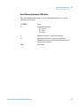
8 Test Functions
This chapter describes the detector’s built in test functions.
9 Maintenance
This chapter provides general information on maintenance of the detector.
10 Parts and Materials for Maintenance
This chapter provides information on parts for maintenance.
11 Identifying Cables
This chapter provides information on cables used with the Agilent 1200
Infinity Series modules.
12 Hardware Information
This chapter describes the detector in more detail on hardware and
electronics.
13 LAN Configuration
This chapter provides information on connecting the module to the Agilent
ChemStation PC.
14 Appendix
This chapter provides addition information on safety, legal and web.
4
Agilent 1290 Infinity II VWD User Manual
Contents
Contents
1 Introduction to the Variable Wavelength Detector
9
Introduction to the Detector 10
Product Description 11
Optical System Overview 12
Dual-Wavelength Mode 17
Leak and Waste Handling 18
Operating Principle 21
2 Site Requirements and Specifications
Site Requirements 24
Physical Specifications 27
Performance Specifications G7114B
3 Using the Module
23
28
31
Magnets 32
Turn on/off 33
Status Indicators 34
Instrument Configuration 35
Set up the Detector with Agilent Open Lab ChemStation
The Detector User Interface 38
Detector Control Settings 40
Method Parameter Settings 41
Scanning with the VWD 45
4 Preparing the Module
37
47
Leak and Waste Handling 48
Setting up an Analysis 50
Solvent Information 57
Agilent 1290 Infinity II VWD User Manual
5
Contents
5 Optimizing the Detector
63
Introduction 64
Match the Flow Cell to the Column
Set the Detector Parameters 68
Warm up of the Detector 69
6 Troubleshooting and Diagnostics
65
71
Available Tests versus Interfaces 72
Agilent Lab Advisor Software 73
7 Error Information
75
What Are Error Messages 77
General Error Messages 78
Detector Error Messages 85
8 Test Functions
95
Introduction 96
Intensity Test 97
Cell Test 100
Wavelength Verification-Calibration
ASTM Drift and Noise Test 104
Quick Noise Test 105
Dark Current Test 107
Holmium Oxide Test 109
D/A Converter (DAC) Test 112
Other Lab Advisor Functions 115
9 Maintenance
102
117
Introduction to Maintenance 118
Warnings and Cautions 118
Overview of Maintenance 120
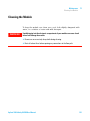
Cleaning the Module 121
Remove and Install the Doors 122
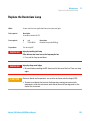
Replace the Deuterium Lamp 123
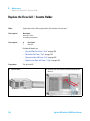
Replace the Flow Cell / Cuvette Holder
Repairing the Flow Cells 128
6
126
Agilent 1290 Infinity II VWD User Manual
Contents
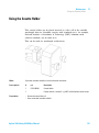
Using the Cuvette Holder 131
Correcting Leaks 133
Replacing Leak Handling System Parts
Replace the Module Firmware 136
10 Parts and Materials for Maintenance
135
139
Overview of Maintenance Parts 140
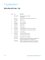
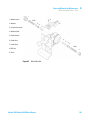
Standard Flow Cell 10 mm / 14 µL 142
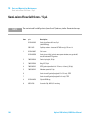
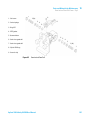
Micro Flow Cell 3 mm / 2 µL 144
Semi-micro Flow Cell 6 mm / 5 µL 146
High Pressure Flow Cell 10 mm / 14 µL 148
Cuvette Holder 150
Accessory Kit 151
11 Identifying Cables
153
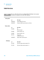
Cable Overview 154
Analog Cables 156
Remote Cables 158
CAN/LAN Cables 162
RS-232 Cables 163
USB Cables 164
12 Hardware Information
165
Firmware Description 166
Electrical Connections 169
Interfaces 172
Setting the 6-bit Configuration Switch
Instrument Layout 183
Early Maintenance Feedback 184
Agilent 1290 Infinity II VWD User Manual
179
7
Contents
13 LAN Configuration
187
What You Have to Do First 188
TCP/IP parameter configuration 189
Configuration Switch 190
Initialization Mode Selection 191
Dynamic Host Configuration Protocol (DHCP)
Manual Configuration 198
PC and Agilent ChemStation Setup 202
14 Appendix
195
211
General Safety Information 212
Waste Electrical and Electronic Equipment Directive
Radio Interference 221
Sound Emission 222
Solvent Information 223
Declaration of Conformity for HOX2 Filter 224
Agilent Technologies on Internet 225
8
220
Agilent 1290 Infinity II VWD User Manual
Agilent 1290 Infinity II VWD User Manual
1
Introduction to the Variable Wavelength
Detector
Introduction to the Detector
Product Description
10
11
Optical System Overview 12
Flow Cell 13
Lamp 14
Source Lens Assembly 14
Entrance Slit Assembly 14
Filter Assembly 15
Mirror Assemblies M1 and M2 16
Grating Assembly 16
Beam Splitter Assembly 16
Photo Diodes Assemblies 16
Photo Diode ADC (analog-to-digital converter)
Dual-Wavelength Mode
Leak and Waste Handling
Waste Concept 20
Operating Principle
16
17
18
21
This chapter gives an introduction to the detector, instrument overview and
internal connectors.
Agilent Technologies
9
1
Introduction to the Variable Wavelength Detector
Introduction to the Detector
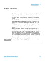
Introduction to the Detector
The Agilent variable wavelength detectors described in this manual are
designed for highest optical performance, GLP compliance and easy
maintenance with:
• higher data rate up to 240 Hz for ultra- fast- HPLC (G7114B),
• deuterium lamp for highest intensity and lowest detection limit over a
wavelength range of 190 to 600 nm,
• optional flow- cell cartridges (standard 10 mm, 14 µL; high pressure
10 mm, 14 µL; micro 3 mm, 2 µL; semi- micro 6 mm, 5 µL) and Prep
Cells are available and can be used depending on the application needs
(other types may be introduced later),
• Dual wavelength mode, see “Dual- Wavelength Mode” on page 17.
• easy front access to lamp and flow cell for fast replacement,
• electronic identification of flow cell and lamp with RFID (Radio
Frequency Identification) tag for unambiguous identification,
• lamp information: part number, serial number, production date,
ignitions, burn time
• cell information: part number, serial number, production date,
nominal path length, volume, maximum pressure
• built- in electronic temperature control (ETC) for improved baseline
stability, and
• built- in holmium oxide filter for fast wavelength accuracy verification.
10
Agilent 1290 Infinity II VWD User Manual
Introduction to the Variable Wavelength Detector
Product Description
1
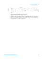
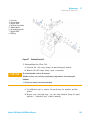
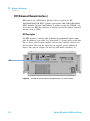
Product Description
The Agilent 1290 Infinity II Variable Wavelength Detector (VWD) is the
most sensitive and fastest detector in its class.
Time- programmable wavelength switching provides sensitivity and
selectivity for your applications.
More sample information can be acquired in the dual wavelength mode.
Low detector noise (<±1.5 µAU) and baseline drift (< 1 x 10- 4 AU/h)
facilitates precise quantification of trace levels components.
High productivity can be achieved with fast analysis at up to 240 Hz data
rates.
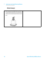
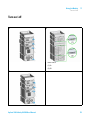
HiVijh^cY^XVidg
;adlXZaa
AVbe]djh^c\l^cYdl
VcYV^g^caZi
EdlZghl^iX]
AZV`YgV^c
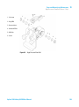
Figure 1
Overview of the Variable Wavelength Detector
Agilent 1290 Infinity II VWD User Manual
11
1
Introduction to the Variable Wavelength Detector
Optical System Overview
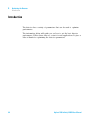
Optical System Overview
The optical system of the detector is shown in the figure below. Its
radiation source is a deuterium- arc discharge lamp for the ultraviolet (UV)
wavelength range from 190 to 600 nm. The light beam from the deuterium
lamp passes through a lens, a filter assembly, an entrance slit, a spherical
mirror (M1), a grating, a second spherical mirror (M2), a beam splitter,
and finally through a flow cell to the sample diode. The beam through the
flow cell is absorbed depending on the solutions in the cell, in which UV
absorption takes place, and the intensity is converted to an electrical
signal by means of the sample photodiode. Part of the light is directed to
the reference photodiode by the beam splitter to obtain a reference signal
for compensation of intensity fluctuation of the light source. A slit in front
of the reference photodiode cuts out light of the sample bandwidth.
Wavelength selection is made by rotating the grating, which is driven
directly by a stepper motor. This configuration allows fast change of the
wavelength. The cutoff filter is moved into the lightpath above 370 nm to
reduce higher order light.
9ZjiZg^jbaVbe
;^aiZgVhhZbWan
:cigVcXZha^i
AZch
B^ggdgB&
HVbeaZY^dYZ
<gVi^c\
;adlXZaa
B^ggdgB'
7ZVbhea^iiZg
GZ[ZgZcXZY^dYZ
Figure 2
12
Optical Path of the Variable Wavelength Detector
Agilent 1290 Infinity II VWD User Manual
Introduction to the Variable Wavelength Detector
Optical System Overview
1
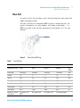
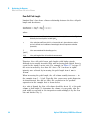
Flow Cell
A variety of flow- cell cartridges can be inserted using the same quick and
simple mounting system.
The flow cells have an integrated RFID tag that contains the flow cell
specific information (e.g. part number, cell volume, path length, ...). A
RFID tag reader reads out this information and transfers it to the user
interface.
G;>9iV\
Figure 3
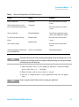
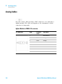
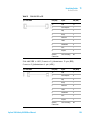
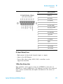
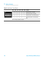
Table 1
Flow Cell with RFID tag
Flow Cell Data
STD
Semi-micro
Micro
High Pressure
Maximum pressure
40 (4)
40 (4)
120 (12)
400 (40)
bar
(MPa)
Path length
10 (conical)
6 (conical)
3 (conical)
10 (conical)
mm
Volume
14
5
2
14
µL
Inlet i.d.
0.25
0.17
0.12
0.25
mm
Inlet length
750
250
310
750
mm
Outlet i.d.
0.30
0.17
0.17
0.17
mm
Outlet length
120
120
120
120
mm
Total volume
60.77
14.49
14.00
60.77
µL
Materials in contact
with solvent
SST, quartz, PTFE,
PEEK
SST, quartz, PTFE
SST, quartz, PTFE
SST, quartz, Kapton
Agilent 1290 Infinity II VWD User Manual
13
1
Introduction to the Variable Wavelength Detector
Optical System Overview
Lamp
The light source for the UV wavelength range is a deuterium lamp. As a
result of plasma discharge in a low pressure deuterium gas, the lamp
emits light over the 190 – 600 nm wavelength range.
The lamp has an integrated RFID tag that contains the lamp specific
information (e.g. part number, burn time, ...). A RFID tag reader reads out
this information and transfers it to the user interface.
Source Lens Assembly
The source lens receives the light from the deuterium lamp and focuses it
onto the entrance slit.
Entrance Slit Assembly
The entrance slit assembly has an exchangeable slit. The standard one has
a 1- mm slit. For replacement and calibration purposes to optimize the
alignment, a slit with a hole is needed.
14
Agilent 1290 Infinity II VWD User Manual
Introduction to the Variable Wavelength Detector
Optical System Overview
1
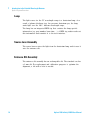
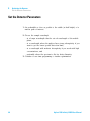
Filter Assembly
The filter assembly is electromechanically actuated. During wavelength
calibrations it moves into the light path.
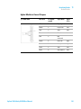
8jid[[;^aiZgeajh=dab^jbDm^YZ;^aiZg
H]jiiZg
8jid[[;^aiZg
Figure 4
Filter Assemby
The filter assembly has two filters installed and is processor- controlled.
OPEN
nothing in light path at λ < 370 nm
CUTOFF
cut off filter in light path at λ > 370 nm
HOLMIU
M
holmium oxide filter for wavelength check
SHUTTER
for measurement of dark current of photo
diodes
A photo sensor determines the correct position.
Agilent 1290 Infinity II VWD User Manual
15
1
Introduction to the Variable Wavelength Detector
Optical System Overview
Mirror Assemblies M1 and M2
The instrument contains two spherical mirrors (M1 and M2). The beam
adjustable is vertically and horizontally. Both mirrors are identical.
Grating Assembly
The grating separates the light beam into all its component wavelengths
and reflects the light onto mirror #2.
The stepper motor reference position is determined by a plate fitted onto
the motor shaft, interrupting the beam of a photo sensor. The wavelength
calibration of the grating is done at the zero order light position and at
656 nm, which is the emission line of the deuterium lamp.
Beam Splitter Assembly
The beam splitter splits the light beam. One part goes directly to the
sample diode. The other part of the light beam goes to the reference
diode.
Photo Diodes Assemblies
Two photo diode assemblies are installed in the optical unit. The sample
diode assembly is located on the left side of the optical unit. The
reference diode assembly is located in the front of the optical unit.
Photo Diode ADC (analog-to-digital converter)
The photo diode current is directly converted to digital data direct photo
current digitalization. The data is transferred to the detector main board .
The photo diode ADC boards are located close to the photo diodes.
16
Agilent 1290 Infinity II VWD User Manual
Introduction to the Variable Wavelength Detector
Dual-Wavelength Mode
1
Dual-Wavelength Mode
The detector provides a Dual- Wavelength mode that offers additional
operation functions.
Features:
• 200 ms acquisition time per data point
• 5 Hz data rate distributed to two channels
• 2.5 Hz data rate for each channel,
• delta wavelength max. 150 nm,
• scans during Dual- Wavelength mode are possible,
• the second order filter is disabled when one wavelength is < 370 nm.
Timetable:
• Wavelength settings are timetable programmable (depends if enough
time for implementation is available),
• switching from Single- Wavelength mode to Dual- Wavelength mode is
NOT timetable programmable,
• filter settings are not timetable programmable.
Agilent 1290 Infinity II VWD User Manual
17
1
Introduction to the Variable Wavelength Detector
Leak and Waste Handling
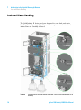
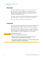
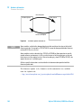
Leak and Waste Handling
The 1290 Infinity II Series has been designed for safe leak and waste
handling. It is important that all security concepts are understood and
instructions are carefully followed.
Figure 5
18
Leak and waste handling concept (overview - typical stack configuration as an
example)
Agilent 1290 Infinity II VWD User Manual
Introduction to the Variable Wavelength Detector
Leak and Waste Handling
1
The solvent cabinet is designed to store a maximum volume of 6 L solvent.
The maximum volume for an individual bottle stored in the solvent cabinet
should not exceed 4 L. For details, see the usage guideline for the Agilent
1200 Infinity Series Solvent Cabinets (a printed copy of the guideline has
been shipped with the solvent cabinet, electronic copies are available on
the Internet).
All leak plane outlets are situated in a consistent position so that all
Infinity and Infinity II modules can be stacked on top of each other. Waste
tubes are guided through a channel on the right hand side of the
instrument, keeping the front access clear from tubes.
The leak plane provides leak management by catching all internal liquid
leaks, guiding them to the leak sensor for leak detection, and passing
them on to the next module below, if the leak sensor fails. The leak sensor
in the leak plane stops the running system as soon as the leak detection
level is reached.
Solvent and condensate is guided through the waste channel into the
waste container:
• from the detector's flow cell outlet
• from the Multisampler needle wash port
• from the Sample Cooler (condensate)
• from the Seal Wash Sensor
• from the pump's Purge Valve or Multipurpose Valve
The waste tube connected to the leak pan outlet on each of the bottom
instruments guides the solvent to a suitable waste container.
Agilent 1290 Infinity II VWD User Manual
19
1
Introduction to the Variable Wavelength Detector
Leak and Waste Handling
Waste Concept
1 Agilent recommends using the 6 L waste can with 1 Stay
Safe cap GL45 with 4 ports (5043-1221) for optimal and
safe waste disposal. If you decide to use your own waste
solution, make sure that the tubes don't immerse in the
liquid.
20
Agilent 1290 Infinity II VWD User Manual
1
Introduction to the Variable Wavelength Detector
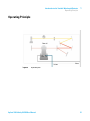
Operating Principle
Operating Principle
;adlXZaa
Dji >c
8dajbc
Figure 6
LVhiZ
Hydraulic path
Agilent 1290 Infinity II VWD User Manual
21
1
22
Introduction to the Variable Wavelength Detector
Operating Principle
Agilent 1290 Infinity II VWD User Manual
Agilent 1290 Infinity II VWD User Manual
2
Site Requirements and Specifications
Site Requirements
24
Physical Specifications
27
Performance Specifications G7114B
28
This chapter gives information on environmental requirements, physical and
performance specifications.
Agilent Technologies
23
2
Site Requirements and Specifications
Site Requirements
Site Requirements
A suitable environment is important to ensure optimal performance of the
instrument.
Power Consideration
The detector power supply has wide ranging capabilities, see “Physical
Specifications” on page 27. It accepts any line voltage in the above
mentioned range. Consequently, there is no voltage selector in the rear of
the detector. There are also no externally accessible fuses, because
automatic electronic fuses are implemented in the power supply.
WA R N I N G
Instrument is partially energized when switched off
The power supply still uses some power, even when the power switch on the front
panel is turned OFF. Repair work at the detector can lead to personal injuries, e. g.
shock hazard, when the detector cover is opened and the instrument is connected to
power.
➔ To disconnect the detector from the power line, unplug the power cord.
WA R N I N G
Hazard of electrical shock or damage of your instrumentation
can result, if the devices are connected to a line voltage higher than specified.
➔ Connect your instrument to the specified line voltage only.
CAUTION
Inaccessible power plug.
In case of emergency it must be possible to disconnect the instrument from the power
line at any time.
➔ Make sure the power connector of the instrument can be easily reached and
unplugged.
➔ Provide sufficient space behind the power socket of the instrument to unplug the
cable.
24
Agilent 1290 Infinity II VWD User Manual
2
Site Requirements and Specifications
Site Requirements
Power Cords
Different power cords are offered as options with the module. The female
end of all power cords is identical. It plugs into the power- input socket at
the rear. The male end of each power cord is different and designed to
match the wall socket of a particular country or region.
WA R N I N G
Absence of ground connection or use of unspecified power cord
The absence of ground connection or the use of unspecified power cord can lead to
electric shock or short circuit.
➔ Never operate your instrumentation from a power outlet that has no ground
connection.
➔ Never use a power cord other than the Agilent Technologies power cord designed
for your region.
WA R N I N G
Use of unsupplied cables
Using cables not supplied by Agilent Technologies can lead to damage of the
electronic components or personal injury.
➔ Never use cables other than the ones supplied by Agilent Technologies to ensure
proper functionality and compliance with safety or EMC regulations.
WA R N I N G
Unintended use of supplied power cords
Using power cords for unintended purposes can lead to personal injury or damage of
electronic equipment.
➔ Never use the power cords that Agilent Technologies supplies with this instrument
for any other equipment.
Agilent 1290 Infinity II VWD User Manual
25
2
Site Requirements and Specifications
Site Requirements
Bench Space
The detector dimensions and weight (see “Physical Specifications” on
page 27) allows you to place the detector on almost any desk or
laboratory bench. It needs an additional 2.5 cm (1.0 inch) of space on
either side and approximately 8 cm (3.1 inch) in the rear for air
circulation and electric connections.
If the bench should carry an Agilent 1200 Infinity Series system, make
sure that the bench is designed to bear the weight of all modules.
The detector should be operated in a horizontal position.
Environment
Your detector will work within specifications at ambient temperatures and
relative humidity as described in “Physical Specifications” on page 27.
Better drift performance depends on better control of the temperature
fluctuations. To realize the highest performance, minimize the frequency
and the amplitude of the temperature changes to below 1 °C/hour (1.8
°F/hour). Turbulences around one minute or less can be ignored.
CAUTION
Condensation within the module
Condensation can damage the system electronics.
➔ Do not store, ship or use your module under conditions where temperature
fluctuations could cause condensation within the module.
➔ If your module was shipped in cold weather, leave it in its box and allow it to warm
slowly to room temperature to avoid condensation.
26
Agilent 1290 Infinity II VWD User Manual
2
Site Requirements and Specifications
Physical Specifications
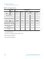
Physical Specifications
Table 2
Physical Specifications
Type
Specification
Weight
11 kg (24.3 lbs)
Dimensions
(height × width × depth)
140 x 396 x 436 mm
(5.5 x 15.6 x 17.2 inches)
Line voltage
100 – 240 V~, ± 10 %
Line frequency
50 or 60 Hz, ± 5 %
Power consumption
80 VA, 70 W
Ambient operating
temperature
4 - 55 °C (39 - 131 °F)
Ambient non-operating
temperature
-40 – 70 °C (-40 – 158 °F)
Humidity
< 95 % r.h. at 40 °C (104 °F)
Operating altitude
Up to 2000 m (6562 ft)
Non-operating altitude
Up to 4600 m (15092 ft)
For storing the module
Safety standards:
IEC, EN, CSA, UL
Installation category II, Pollution degree 2
For indoor use only.
Agilent 1290 Infinity II VWD User Manual
Comments
Wide-ranging
capability
Non-condensing
27
2
Site Requirements and Specifications
Performance Specifications G7114B
Performance Specifications G7114B
Performance Specifications
Table 3
28
Agilent 1290 Infinity II Variable Wavelength Detector (G7114B) Performance
Specifications
Feature
Specification
Detection type
Double-beam photometer
Light source
Deuterium lamp
Number of signals
Single and dual wavelength detection
Maximum data rate
240 Hz (single wavelength detection)
2.5 Hz (dual wavelength detection)
Noise
<±0.15·10-5 AU, at 230 nm (single wavelength detection)
<±0.80·10-5 AU, at 230 nm and 254 nm (dual wavelength detection)
Drift
<1·10-4 AU/h, at 230 nm
Linearity
>2.5 AU upper limit
Wavelength range
190 – 600 nm
Wavelength
accuracy
±1 nm, self-calibration with deuterium lines, verification with holmium
oxide filter
Wavelength
precision
<±0.1 nm
Slit width
6.5 nm typical over whole wavelength range
Time programmable
Wavelength, polarity, peak width, lamp on/off
Agilent 1290 Infinity II VWD User Manual
2
Site Requirements and Specifications
Performance Specifications G7114B
Table 3
Agilent 1290 Infinity II Variable Wavelength Detector (G7114B) Performance
Specifications
Feature
Specification
Flow cells
Standard: 14 µL volume, 10 mm cell path length and 40 bar (588 psi)
pressure maximum
Micro: 2 µL volume, 3 mm cell path length and 120 bar (1760 psi) pressure
maximum
Semi-micro: 5 µL volume, 6 mm cell path length and 40 bar (588 psi)
pressure maximum
Preparative: 4 µL volume, 3 mm cell path length and 120 bar (1760 psi)
pressure maximum
Preparative: 0.3 mm cell path length and 50 bar (725 psi) pressure
maximum
Preparative: 0.06 mm cell path length and 50 bar (725 psi) pressure
maximum
Spectral tools
Stop-flow wavelength scan
Analog output
Recorder/Integrator 100 mV or 1 V, 1 output
Communication
LAN, Controller-area network (CAN),
ERI: ready, start, stop and shut-down signals
GLP
Early maintenance feedback (EMF) for continuous tracking of instrument
usage in terms of lamp burn time with user settable limits and feedback
messages. Electronic records of maintenance and errors. RFID for
electronics records of flow cell and UV lamp conditions (path length,
volume, product number, serial number, test passed, and usage).
Verification of wavelength accuracy with built-in holmium oxide filter.
Safety and
maintenance
Extensive diagnostics, error detection and display through Agilent Instant
Pilot and Agilent Lab Advisor software. Leak detection, safe leak handling,
leak output signal for shutdown of pumping system. Low voltages in major
maintenance areas. Tracking of flow cells and lamps with RFID (radio
frequency identification) tags
Agilent 1290 Infinity II VWD User Manual
29
2
Site Requirements and Specifications
Performance Specifications G7114B
Specification Conditions G7114B
ASTM: “Standard Practice for Variable Wavelength Photometric Detectors
Used in Liquid Chromatography”.
Reference conditions: Standard flow cell, path length 10 mm, flow
1 mL/min LC- grade methanol.
Noise:
± 1.5·10- 6 AU at 230 nm, TC 2 s
RT = 2.2 * TC
Linearity:
Linearity is measured with caffeine at 265 nm.
NOTE
The specification are based on the the standard RFID tag lamp (G1314-60101) and may be
not achieved when other lamp types or aged lamps are used.
ASTM drift tests require a temperature change below 2°C/hour
(3.6°F/hour) over one hour period. Our published drift specification is
based on these conditions. Larger ambient temperature changes will result
in larger drift.
Better drift performance depends on better control of the temperature
fluctuations. To realize the highest performance, minimize the frequency
and the amplitude of the temperature changes to below 1°C/hour
(1.8°F/hour). Turbulences around one minute or less can be ignored.
Performance tests should be done with a completely warmed up optical
unit (> one hour). ASTM measurements require that the detector should
be turned on at least 24 hours before start of testing.
30
Agilent 1290 Infinity II VWD User Manual
Agilent 1290 Infinity II VWD User Manual
3
Using the Module
Magnets
Turn on/off
32
33
Status Indicators
34
Instrument Configuration
35
Set up the Detector with Agilent Open Lab ChemStation
The Detector User Interface
Detector Control Settings
38
40
Method Parameter Settings
Scanning with the VWD
37
41
45
This chapter explains the essential operational parameters of the module.
Agilent Technologies
31
3
Using the Module
Magnets
Magnets
32
Agilent 1290 Infinity II VWD User Manual
Using the Module
Turn on/off
3
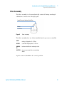
Turn on/off
1
2
Power switch
(1) On
(2) Off
3
Agilent 1290 Infinity II VWD User Manual
33
3
Using the Module
Status Indicators
Status Indicators
1 The module status indicator indicates one of six possible
module conditions:
Status indicators
1. Idle
2. Run mode
3. Not-ready. Waiting for a specific pre-run condition to
be reached or completed.
4. Error mode - interrupts the analysis and requires
attention (for example a leak or defective internal
components).
5. Resident mode (blinking) - for example during update
of main firmware.
6. Bootloader mode (fast blinking). Try to re-boot the
module or try a cold-start. Then try a firmware update.
34
Agilent 1290 Infinity II VWD User Manual
Using the Module
Instrument Configuration
3
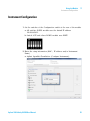
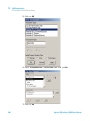
Instrument Configuration
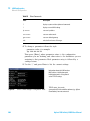
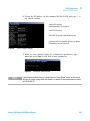
1 Set the switches of the Configuration switch at the rear of the module:
a All switches DOWN: module uses the default IP address
192.168.254.11.
b Switch 4 UP and others DOWN: module uses DHCP.
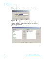
2 Enter the setup information (MAC / IP address and/or Instrument
Name).
a Agilent OpenLab ChemStation (Configure Instrument):
Agilent 1290 Infinity II VWD User Manual
35
3
Using the Module
Instrument Configuration
b Lab Advisor (Instrument Overview - Add Instrument):
36
Agilent 1290 Infinity II VWD User Manual
3
Using the Module
Set up the Detector with Agilent Open Lab ChemStation
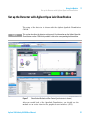
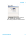
Set up the Detector with Agilent Open Lab ChemStation
The setup of the detector is shown with the Agilent OpenLab ChemStation
C.01.06.
NOTE
This section describes the detector settings only. For information on the Agilent OpenLab
ChemStation or other 1200 Infinity modules refer to the corresponding documentation.
Figure 7
ChemStation Method and Run Control (just detector is shown)
After successful load of the OpenLab ChemStation, you should see the
module as an active item in the graphical user interface (GUI).
Agilent 1290 Infinity II VWD User Manual
37
3
Using the Module
The Detector User Interface
The Detector User Interface
Within the detector GUI, there are active areas. If you move
the mouse cursor across the icons the cursor will change.
1 Lamp: turn on and off of UV-lamp
2 EMF status
3 Detector status
4 Lamp status (on/off) and information (RFID tag)
5 Flow Cell information (RFID tag)
RFID tag information is displayed when moving with the
mouse cursor on to the tag attached to the flow cell or lamp.
The information provides flow cell and lamp related
information like
• Part number
• Production date
• Serial number
and other details.
38
Agilent 1290 Infinity II VWD User Manual
Using the Module
The Detector User Interface
3
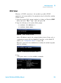
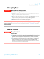
EMF Status shows Run / Ready / Error state and “Not
Ready text” or “Error text”
• Offline (gray)
• Ok. No Maintenance required (green)
• EMF warning. Maintenance might be required (yellow)
• EMF warning. Maintenance required (red)
Important: The EMF settings can be accessed via Agilent
Lab Advisor. The limit(s) can be changed. Based on the limit,
the User Interface displays the above status.
Module Status shows Run / Ready / Error state and “Not
Ready text” or “Error text”
• Error (red)
• Not ready (yellow)
• Ready (green)
• Pre run, Post run (purple)
• Run (blue)
• Idle (green)
• Offline (dark gray)
• Standby (light gray)
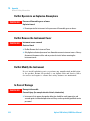
A right-click into the Active Area will open a menu to
• Show the Control Interface (special module settings)
• Show the Method interface (similar as via menu
Instrument > Setup Instrument Method)
• Set Error Method
• Identify Module (Status LED will blink)
• Perform a Balance
• Switch the UV-lamp on/off (same as click on button
“Make Device Ready/Turn device off (standby)”)
• Take / Abort Scans (during flow off)
Agilent 1290 Infinity II VWD User Manual
39
3
Using the Module
Detector Control Settings
Detector Control Settings
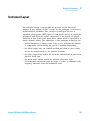
The figure shows the default settings.
• Lamps: can be turned ON/OFF.
• Analog Output Range: can be set to either 100 mV or
1 Vfull scale, for additional settings see “Analog” (under
Table 4 on page 42).
• Temperature Control: The optical unit is kept on
constant temperature (some degrees above ambient)
and improves the baseline stability in unstable
environments, see also “Environment” on page 26.
•
•
•
•
40
If the flow cell temperature is critical for your
chromatography or your environment is stable, you may
set the Temperature Control to off. This will lower the
optical unit and flow cell temperature by some degree.
UV Lamp Tag
• Automatic detects a lamp with RFID tag. If no RFID
tag lamp is used, “UV lamp not ready” is displayed
and it cannot be ignited. A compatible mode has to
be selected based on the used lamp; see
Non-RFID-tag lamp information below.
• Manual (by PN) uses the selected “heating” mode.
This mode can also be used when the RFID tag of the
standard lamp (Deuterium lamp (with RFID tag)
(G1314-60101)) is not recognized (defect RFID tag or
reader).
• Non-RFID-tag lamp: In case a non-RFID-tag lamp is
used, the user interface will show this when
selecting a compatible mode. You may operate the
detector outside of the guaranteed specification. The
correct selection is important for optimal
performance and lifetime.
Cell Tag: Automatic mode for Agilent flow cells with
RFID tags. If no RFID tag cell is used, detector icon will
become gray (cell tag not ready) and analysis is
disabled.
At Power On: automatic lamp-on at power on.
Automatic Turn On: automatic detector power on.
Agilent 1290 Infinity II VWD User Manual
3
Using the Module
Method Parameter Settings
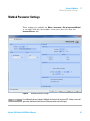
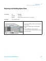
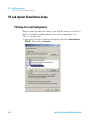
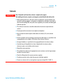
Method Parameter Settings
These settings are available via Menu > Instrument > Set up Instrument Method
or via right click into the module’s active area (does not show the
Instrument Curves tab).
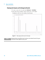
Figure 8
NOTE
Method parameter settings
For additional help and support: Highlight the desired cell and press F1. A help screen will
open with additional information and documentation about the topic.
Agilent 1290 Infinity II VWD User Manual
41
3
Using the Module
Method Parameter Settings
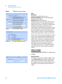
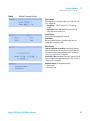
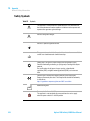
Table 4
Method Parameter Settings
Figure 9
G7114B Peakwidth Settings
Figure 10
G7114B Dual Wavelength Settings
Signal
Wavelength
Single Wavelength (190 – 600 nm, step 1)
Dual Wavelength Mode enables the multi-wavelength
mode with two wavelengths.
Peakwidth (Responsetime, Data Rate)
Peakwidth enables you to select the peak width (response
time) for your analysis. The peak width is defined as the
width of a peak, in minutes, at half the peak height. Set the
peak width to the narrowest expected peak in your
chromatogram. The peak width sets the optimum response
time for your detector. The peak detector ignores any peaks
that are considerably narrower, or wider, than the peak
width setting. The response time is the time between 10 %
and 90 % of the output signal in response to an input step
function. When the All spectrum storage option is selected,
then spectra are acquired continuously depending on the
setting of the peak width. The time specified by the peak
width is used as a factor in the acquisition of spectra. The
acquisition time for one spectrum is slightly less than the
peak width divided by 8, which is the acquisition time.
Limits: When you set the peak width (in minutes), the
corresponding response time is set automatically and the
appropriate data rate for signal and spectra acquisition is
selected.
NOTE
The 1290 Infinity VWD (G7114B) has a data rate of up
to 240 Hz.
Stoptime/Posttime
The stoptime is the time where either the complete system
stops (As Pump/Injector) or the module (if different from
system stop time). The data collection is stopped at this
time. A posttime period can be used to allow module’s items
to equilibrate (e.g. after gradient change or temperature
change).
42
Agilent 1290 Infinity II VWD User Manual
Using the Module
Method Parameter Settings
Table 4
3
Method Parameter Settings
Analog Output
The range can be set to either 100 mV or 1 V full scale, see
Table on page 40.
• Zero Offset: 1 – 99 % in steps of 1 % (5 % equal to
50 mV).
• Attenuation: 0.98 – 4000 mAU at discrete values for
either 100 mV or 1 V full scale.
Signal Polarity
Can be switched to negative (if required).
Autobalance
Defines, whether a balance is performed prior to a run
and/or after a run has finished.
Miscellaneous
Lamp on required for acquisition: If unchecked, the lamp
will be turned off after the analysis has finished. Note that
the lamp on requires at least one hour warm-up time, see
“Warm up of the Detector” on page 69.
Scan Range / Step: Stop-Flow scan range / step. Access to
the scan feature is only possible during run. See “Scanning
with the VWD” on page 45.
Additional Signals (for diagnostic purpose)
• Sample only
• Reference only
Agilent 1290 Infinity II VWD User Manual
43
3
Using the Module
Method Parameter Settings
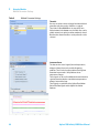
Table 4
Method Parameter Settings
Timetable
You may set up time events to change functions with their
parameters over the run time. Add lines as required.
Time Limits: 0.00 to 99999.00 min in steps of 0.01 min.
Via the buttons in the bottom area, time table lines can be
added, removed, cut copied, pasted or completely cleared.
Based on the chosen function, a certain parameter can be
selected.
Instrument Curves
The detector has several signals (internal temperatures,
voltages of lamps) that can be used for diagnosing
problems. These can be baseline problems deriving from
deuterium lamps wander / drift problems due to
temperature changes.
These signals can be used in addition to the normal baseline
signal to determine whether correlation to temperature or
voltage/current of the lamp.
These signals are available via the Agilent ChemStation
Online Plot/Data Signal and/or Agilent Lab Advisor
Software.
44
Agilent 1290 Infinity II VWD User Manual
3
Using the Module
Scanning with the VWD
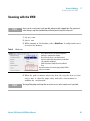
Scanning with the VWD
NOTE
Access to the scan feature is only possible during run with stopped flow. The spectrum is
taken during a stop-flow condition only while the peak is kept in the flow cell.
1 Set up a run.
2 Start a run.
3 While running on the baseline, take a Blank Scan. A background scan is
stored in the memory.
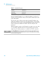
Table 5
Blank scan
•
Step 1: Blank Scan: scan of the background
(solvent) is stored in the memory.
• Step 2: Sample Scan: scan of the peak of
interest is taken while the peak stays in the flow
cell (stop-flow condition).
• Online Spectrum: Sample Scan minus Blank
Scan.
Here the functions are inactive (grayed out). Will be
active in run mode.
4 When the peak of interest enters the flow cell, stop the flow (set flow
rate to zero or open the purge valve) and wait a few moments to
stabilize the concentration.
NOTE
Turning off the pump would stop the run and no access to the sample scan is possible.
Agilent 1290 Infinity II VWD User Manual
45
3
Using the Module
Scanning with the VWD
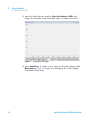
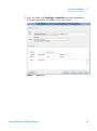
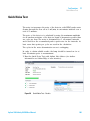
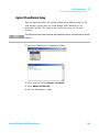
5 Open the Online Spectra window (View > Online Spectra > VWD) and
change the absorbance and wavelength range according your needs.
Figure 11
Online Spectra Window
6 Select Sample Scan. A sample scan is taken in the range defined under
Miscellaneous in Table 4 on page 42 and displays the result (Sample
Scan minus Blank Scan).
46
Agilent 1290 Infinity II VWD User Manual
Agilent 1290 Infinity II VWD User Manual
4
Preparing the Module
Leak and Waste Handling
Waste Concept 49
48
Setting up an Analysis 50
Before Using the System 50
Requirements and Conditions 52
Preparing the Detector 54
Preparing the HPLC System 54
Running the Sample and Verifying the Results
Solvent Information
56
57
This chapter provides information on how to set up the detector for an analysis
and explains the basic settings.
Agilent Technologies
47
4
Preparing the Module
Leak and Waste Handling
Leak and Waste Handling
WA R N I N G
Toxic, flammable and hazardous solvents, samples and reagents
The handling of solvents, samples and reagents can hold health and safety risks.
➔ When working with these substances observe appropriate safety procedures (for
example by wearing goggles, safety gloves and protective clothing) as described in
the material handling and safety data sheet supplied by the vendor, and follow good
laboratory practice.
➔ The volume of substances should be reduced to the minimum required for the
analysis.
➔ Do not operate the instrument in an explosive atmosphere.
➔ Never exceed the maximal permissible volume of solvents (6 L) in the solvent
cabinet.
➔ Do not use bottles that exceed the maximum permissible volume as specified in the
usage guideline for the Agilent 1200 Infinity Series Solvent Cabinets.
➔ Arrange the bottles as specified in the usage guideline for the solvent cabinet.
➔ A printed copy of the guideline has been shipped with the solvent cabinet,
electronic copies are available on the Internet.
➔ Ground the waste container.
➔ The residual free volume in the appropriate waste container must be large enough
to collect the waste liquid.
➔ Check the filling level of the waste container regularly.
➔ To achieve maximal safety, check the correct installation regularly.
➔ Do not use solvents with an auto-ignition temperature below 200 °C (392 °F).
NOTE
Recommendations for Solvent Cabinet
For details, see the usage guideline for the Agilent 1200 Infinity Series Solvent Cabinets.
For correct installation of your system contact your Agilent service
representative.
48
Agilent 1290 Infinity II VWD User Manual
Preparing the Module
Leak and Waste Handling
4
Waste Concept
1 Agilent recommends using the 6 L waste can with 1 Stay
Safe cap GL45 with 4 ports (5043-1221) for optimal and
safe waste disposal. If you decide to use your own waste
solution, make sure that the tubes don't immerse in the
liquid.
Agilent 1290 Infinity II VWD User Manual
49
4
Preparing the Module
Setting up an Analysis
Setting up an Analysis
This chapter can be used for
• preparing the system,
• to learn the set up of an HPLC analysis and
• to use it as an instrument check to demonstrate that all modules of the
system are correctly installed and connected. It is not a test of the
instrument performance.
• Learn about special settings
Before Using the System
Solvent Information
Observe recommendations on the use of solvents in chapter “Solvents” in
the pump’s reference manual.
Priming and Purging the System
When the solvents have been exchanged or the pumping system has been
turned off for a certain time (for example, overnight) oxygen will
re- diffuse into the solvent channel between the solvent reservoir, vacuum
degasser (when available in the system) and the pump. Solvents containing
volatile ingredients will slightly lose these. Therefore priming of the
pumping system is required before starting an application.
50
Agilent 1290 Infinity II VWD User Manual
Preparing the Module
Setting up an Analysis
Table 6
4
Choice of Priming Solvents for Different Purposes
Activity
Solvent
Comments
After an installation
Isopropanol
Best solvent to flush air out of the
system
When switching between reverse
phase and normal phase (both times)
Isopropanol
After an installation
Ethanol or Methanol
Alternative to Isopropanol (second
choice) if no Isopropanol is available
To clean the system when using
buffers
Bidistilled water
Best solvent to re-dissolve buffer
crystals
Best solvent to flush air out of the
system
Bidistilled water
After a solvent change
Best solvent to re-dissolve buffer
crystals
After the installation of normal phase
seals (P/N 0905-1420)
NOTE
Hexane + 5% Isopropanol
Good wetting properties
The pump should never be used for priming empty tubings (never let the pump run dry). Use
a syringe to draw enough solvent for completely filling the tubings to the pump inlet before
continuing to prime with the pump.
1 Open the purge valve of your pump (by turning it counterclockwise)
and set flow rate to 3 – 5 mL/min.
2 Flush all tubes with at least 30 mL of solvent.
3 Set flow to required value of your application and close the purge
valve.
NOTE
Pump for approximately 10minutes before starting your application.
Agilent 1290 Infinity II VWD User Manual
51
4
Preparing the Module
Setting up an Analysis
Requirements and Conditions
What You Will Need
The table below lists the items you need to have for the set up of the
analysis. Some of these are optional (not required for the basic system).
Table 7
What you will need
Agilent 1200 Infinity Series system
Pump (plus degassing)
Autosampler
Detector, standard flow cell installed
Degasser (optional)
Column Compartment (optional)
Agilent CDS
System should be correctly set up for LAN
communication with the Agilent ChemStation
Column:
Zorbax Eclipse XDB-C18, 4.6 x 150 mm, 5 µm
(993967-902) or an equivalent column
Standard:
Agilent isocratic checkout sample
(01080-68704)
Conditions
A single injection of the isocratic test standard is made under the
conditions given in Table 8 on page 52:
Table 8
52
Conditions
Flow
1.5 mL/min
Stoptime
8 min
Solvent
100% (30% water/70% Acetonitrile)
Temperature
Ambient
Wavelength
sample 254 nm
Injection Volume
1 µL
Column Temperature (optional):
25 °C or ambient
Agilent 1290 Infinity II VWD User Manual
Preparing the Module
Setting up an Analysis
4
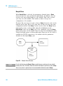
Typical Chromatogram
A typical chromatogram for this analysis is shown in Figure 12 on
page 53. The exact profile of the chromatogram will depend on the
chromatographic conditions. Variations in solvent quality, column packing,
standard concentration and column temperature will all have a potential
effect on peak retention and response.
Figure 12
Typical Chromatogram with UV-detector
Agilent 1290 Infinity II VWD User Manual
53
4
Preparing the Module
Setting up an Analysis
Preparing the Detector
For best performance of the detector
• Let the lamp warm- up and stabilize for at least one hour (initial turn
on of the module requires a longer time depending on the environment
and the application needs); refer to “Specification Conditions
G7114B” on page 30.
• For high sensitivity measurements, a stable environment is required;
refer to “Environment” on page 26. Prevent drafts from air condition
systems.
• Do not work with removed/open front panels/doors. When the system
includes a G1316 TCC (typically located below the detector) and its
front panel is removed while the TCC is set to high temperatures, the
up- streaming air could influence the stability of the detector baseline.
Preparing the HPLC System
1 Turn on the control software and the monitor.
2 Turn on the modules.
3 Start the control software. The screen should show all modules and the
system status is Not Ready.
4 Turn on the modules that require conditioning:
a Detector lamp (warm- up for at least 60 min to get a stable baseline).
b Column compartment (set temperature as required).
c Pump (purge).
d Sampler (prepare the standard isocratic sample into a vial).
e Solvents (fill water and Acetontrile into the solvent bottles).
5 Load the default method.
6 Pump the water/acetonitrile (30/70 %) mobile phase through the column
for 10 min for equilibration.
54
Agilent 1290 Infinity II VWD User Manual
Preparing the Module
Setting up an Analysis
4
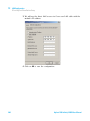
7 Select the menu item Run Control > Sample Info and enter information
about this application. Click OK to leave this screen.
Figure 13
Sample Info
Agilent 1290 Infinity II VWD User Manual
55
4
Preparing the Module
Setting up an Analysis
Running the Sample and Verifying the Results
1 To start a run select the menu item RunControl > Run Method.
2 This will start the modules and the online plot on the Agilent
ChemStation will show the resulting chromatogram.
Figure 14
NOTE
56
Chromatogram with Isocratic Test Sample
Information about using the Data Analysis functions can be obtained from the Using your
ChemStation manual supplied with your system.
Agilent 1290 Infinity II VWD User Manual
4
Preparing the Module
Solvent Information
Solvent Information
Observe the following recommendations on the use of solvents.
• Follow recommendations for avoiding the growth of algae, see pump
manuals.
• Small particles can permanently block capillaries and valves. Therefore,
always filter solvents through 0.4 µm filters.
• Avoid or minimize the use of solvents that may corrode parts in the
flow path. Consider specifications for the pH range given for different
materials like flow cells, valve materials etc. and recommendations in
subsequent sections.
Material Information
Materials in the flow path are carefully selected based on Agilent’s
experiences in developing highest quality instruments for HPLC analysis
over several decades. These materials exhibit excellent robustness under
typical HPLC conditions. For any special conditions, please consult the
material information section or contact Agilent.
Disclaimer
Subsequent data were collected from external resources and are meant as
a reference. Agilent cannot guarantee the correctness and completeness of
such information. Data is based on compatibility libraries, which are not
specific for estimating the long- term life time under specific but highly
variable conditions of UHPLC systems, solvents, solvent mixtures and
samples. Information can also not be generalized due to catalytic effects of
impurities like metal ions, complexing agents, oxygen etc. Apart from pure
chemical corrosion, other effects like electro corrosion, electrostatic
charging (especially for non- conductive organic solvents), swelling of
polymer parts etc. need to be considered. Most data available refers to
room temperature (typically 20 – 25 °C, 68 – 77 °F). If corrosion is
possible, it usually accelerates at higher temperatures. If in doubt, please
consult technical literature on chemical compatibility of materials.
Agilent 1290 Infinity II VWD User Manual
57
4
Preparing the Module
Solvent Information
PEEK
PEEK (Polyether- Ether Ketones) combines excellent properties regarding
biocompatibility, chemical resistance, mechanical and thermal stability.
PEEK is therefore the material of choice for UHPLC and biochemical
instrumentation.
It is stable in a pH range between 1 – 12, and inert to many common
solvents.
There is still a number of known incompatibilities with chemicals such as
chloroform, methylene chloride, THF, DMSO, strong acids (nitric acid >
10 %, sulphuric acid > 10 %, sulfonic acids, trichloroacetic acid), halogenes
or aequous halogene solutions, phenol and derivatives (cresols, salicylic
acid etc.).
Polyimide
Agilent uses semi- crystalline polyimide for rotor seals in valves and needle
seats in autosamplers. One supplier of polyimide is DuPont, which brands
polyimide as Vespel, which is also used by Agilent.
Polyimide is stable in a pH range between 1 and 10 and in most organic
solvents. It is incompatible with concentrated mineral acids (e.g. sulphuric
acid), glacial acetic acid, DMSO and THF. It is also degraded by
nucleophilic substances like ammonia (e.g. ammonium salts in basic
conditions) or acetates.
Polyethylene (PE)
Agilent uses UHMW (ultra- high molecular weight)- PE/PTFE blends for
yellow piston and wash seals, which are used in 1290 Infinity pumps and
for normal phase applications in 1260 Infinity pumps.
Polyethylene has a good stability for most common inorganic solvents
including acids and bases in a pH range of 1 to 12.5. It is compatible to
many organic solvents used in chromatographic systems like methanol,
acetonitrile and isopropanol. It has limited stability with aliphatic,
aromatic and halogenated hydrocarbons, THF, phenol and derivatives,
concentrated acids and bases. For normal phase applications, the
maximum pressure should be limited to 200 bar.
58
Agilent 1290 Infinity II VWD User Manual
4
Preparing the Module
Solvent Information
Tantalum (Ta)
Tantalum is inert to most common HPLC solvents and almost all acids
except fluoric acid and acids with free sulfur trioxide. It can be corroded
by strong bases (e.g. hydroxide solutions > 10 %, diethylamine). It is not
recommended for the use with fluoric acid and fluorides.
Stainless Steel (ST)
Stainless steel is inert against many common solvents. It is stable in the
presence of acids and bases in a pH range of 1 to 12.5. It can be corroded
by acids below pH 2.3. It can also corrode in following solvents:
• Solutions of alkali halides, their respective acids (for example, lithium
iodide, potassium chloride, and so on) and aqueous solutions of
halogens.
• High concentrations of inorganic acids like nitric acid, sulfuric acid and
organic solvents especially at higher temperatures (replace, if your
chromatography method allows, by phosphoric acid or phosphate buffer
which are less corrosive against stainless steel).
• Halogenated solvents or mixtures which form radicals and/or acids, for
example:
2 CHCl3 + O2→ 2 COCl2 + 2 HCl
This reaction, in which stainless steel probably acts as a catalyst,
occurs quickly with dried chloroform if the drying process removes the
stabilizing alcohol.
• Chromatographic grade ethers, which can contain peroxides (for
example, THF, dioxane, di- isopropylether). Such ethers should be
filtered through dry aluminium oxide which adsorbs the peroxides.
• Solutions of organic acids (acetic acid, formic acid, and so on) in
organic solvents. For example, a 1 % solution of acetic acid in methanol
will attack steel.
• Solutions containing strong complexing agents (for example, EDTA,
ethylene diamine tetra- acetic acid).
• Mixtures of carbon tetrachloride with 2- propanol or THF.
Agilent 1290 Infinity II VWD User Manual
59
4
Preparing the Module
Solvent Information
Diamond-Like Carbon (DLC)
Diamond- Like Carbon is inert to almost all common acids, bases and
solvents. There are no documented incompatibilities for HPLC applications.
Fused silica and Quartz (SiO2)
Fused silica is used in 1290 Infinity Flow Cells and capillaries. Quartz is
used for classical flow cell windows. It is inert against all common
solvents and acids except hydrofluoric acid and acidic solvents containing
fluorides. It is corroded by strong bases and should not be used above pH
12 at room temperature. The corrosion of flow cell windows can negatively
affect measurement results. For a pH greater than 12, the use of flow cells
with sapphire windows is recommended.
Gold
Gold is inert to all common HPLC solvents, acids and bases within the
specified pH range. It can be corroded by complexing cyanides and
concentrated acids like aqua regia.
Zirconium Oxide (ZrO2)
Zirconium Oxide is inert to almost all common acids, bases and solvents.
There are no documented incompatibilities for HPLC applications.
Platinum/Iridium
Platinum/Iridium is inert to almost all common acids, bases and solvents.
There are no documented incompatibilities for HPLC applications.
Fluorinated polymers (PTFE, PFA, FEP, FFKM)
Fluorinated polymers like PTFE (polytetrafluorethylene), PFA
(perfluoroalkoxy) and FEP (fluorinated ethylene propylene) are inert to
almost all common acids, bases, and solvents. FFKM is perfluorinated
rubber, which is also resistant to most chemicals. As an elastomer, it may
swell in some organic solvents like halogenated hydrocarbons.
TFE/PDD copolymer tubings, which are used in all Agilent degassers
except 1322A, are not compatible with fluorinated solvents like Freon,
Fluorinert, or Vertrel. They have limited life time in the presence of
60
Agilent 1290 Infinity II VWD User Manual
Preparing the Module
Solvent Information
4
Hexafluoroisopropanol (HFIP). To ensure the longest possible life with
HFIP, it is best to dedicate a particular chamber to this solvent, not to
switch solvents, and not to let dry out the chamber. For optimizing the life
of the pressure sensor, do not leave HFIP in the chamber when the unit is
off.
Sapphire, Ruby and Al2O3-based ceramics
Sapphire, ruby and ceramics based on aluminum oxide Al2O3 are inert to
almost all common acids, bases and solvents. There are no documented
incompatibilities for HPLC applications.
Agilent 1290 Infinity II VWD User Manual
61
4
62
Preparing the Module
Solvent Information
Agilent 1290 Infinity II VWD User Manual
Agilent 1290 Infinity II VWD User Manual
5
Optimizing the Detector
Introduction
64
Match the Flow Cell to the Column
Set the Detector Parameters
Warm up of the Detector
65
68
69
This chapter provides information on how to optimize the detector.
Agilent Technologies
63
5
Optimizing the Detector
Introduction
Introduction
The detector has a variety of parameters that can be used to optimize
performance.
The information below will guide you on how to get the best detector
performance. Follow these rules as a start for new applications. It gives a
rule- of- thumb for optimizing the detector parameters.
64
Agilent 1290 Infinity II VWD User Manual
Optimizing the Detector
Match the Flow Cell to the Column
5
Match the Flow Cell to the Column
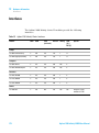
The tables below recommend the flow cell that matches the column used.
If more than one selection is appropriate, use the larger flow cell to get
the best detection limit. Use the smaller flow cell for best peak resolution.
Standard HPLC Applications
Figure 15
Choosing a Flow Cell (Standard HPLC Applications)
Ultra fast separation with RRLC systems
Figure 16
Choosing a Flow Cell for G7114B (for ultra fast separation with RRLC systems)
• (+) For ultra fast analysis with step gradients the micro flow cell (2 µL,
3 mm) gives the best performance
• (++) In high resolution analysis time is not the highest priority. Higher
delay volumes are accepted. Therefore we recommend to use the
damper plus mixer for a highest signal to noise.
• If longer columns (> 50 mm) for higher resolution are used, then the
next larger flow cell is the preferred choice for higher sensitivity.
Agilent 1290 Infinity II VWD User Manual
65
5
Optimizing the Detector
Match the Flow Cell to the Column
Flow Cell Path Length
Lambert- Beer’s law shows a linear relationship between the flow cell path
length and absorbance.
where
T
is the transmission, defined as the quotient of the intensity of the transmitted light I
divided by the intensity of the incident light, I0,
e
is the extinction coefficient, which is a characteristic of a given substance under a
precisely-defined set of conditions of wavelength, solvent, temperature and other
parameters,
C
[mol/L]
is the concentration of the absorbing species,
d [m]
is the path length of the cell used for the measurement.
Therefore, flow cells with longer path lengths yield higher signals.
Although noise usually increases little with increasing path length, there is
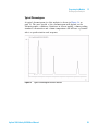
a gain in the signal- to- noise ratio. For example, in Figure 17 on page 67
the noise increased by less than 10 % but a 70 % increase in signal
intensity was achieved by increasing the path length from 6 mm to
10 mm.
When increasing the path length, the cell volume usually increases — in
the example from 5 – 14 µL. Typically, this causes more peak dispersion.
As demonstrated, this did not affect the resolution in the gradient
separation in the example that is shown below.
As a rule- of- thumb, the flow cell volume should be about 1/3 of the peak
volume at half height. To determine the volume of your peaks, take the
peak width as reported in the integration results multiply it by the flow
rate and divide it by 3).
66
Agilent 1290 Infinity II VWD User Manual
Optimizing the Detector
Match the Flow Cell to the Column
5
6cVanh^hd[eZhi^X^YZhiVcYVgY
6WhdgWVcXZ
+"bbdei^XVaeVi]aZc\i]
&%"bbdei^XVaeVi]aZc\i]
I^bZb^c
Figure 17
Influence of Cell Path Length on Signal Height
Traditionally LC analysis with UV detectors is based on comparing
measurements with internal or external standards. To check photometric
accuracy of the detector, it is necessary to have more precise information
on path lengths of the flow cells.
The correct response is:
expected response * correction factor
Please find below the details of the flow cells:
Table 9
Correction factors for Agilent VWD flow cells
Part number
Path length (actual)
Correction factor
Standard flow cell 10 mm, 14 µL, 40 bar (G1314-60186)
10.15 ± 0.19 mm
10/10.15
Semi-micro flow cell 6 mm, 5 µL (G1314-60183)
6.10 ± 0.19 mm
6/6.10
Micro flow cell 3 mm, 2 µL, 120 bar (G1314-60187)
2.80 ± 0.19 mm
3/2.8
High pressure flow cell 10 mm, 14 µL, 400 bar (G1314-60182)
10.00 ± 0.19 mm
10/10
NOTE
However you have to be aware that there is additional tolerance of gasket thickness and its
compression ratio which is supposed to be very small in comparison with the machining
tolerance.
Agilent 1290 Infinity II VWD User Manual
67
5
Optimizing the Detector
Set the Detector Parameters
Set the Detector Parameters
1 Set peakwidth as close as possible to the width (at half height) of a
narrow peak of interest.
2 Choose the sample wavelength.
• at a longer wavelength than the cut- off wavelength of the mobile
phase,
• at a wavelength where the analytes have strong absorptivity if you
want to get the lowest possible detection limit,
• at a wavelength with moderate absorptivity if you work with high
concentrations, and
• preferably where the spectrum is flat for better linearity.
3 Consider to use time- programming to further optimization.
68
Agilent 1290 Infinity II VWD User Manual
Optimizing the Detector
Warm up of the Detector
5
Warm up of the Detector
Give the optical unit enough time to warm- up and stabilize (> 60
minutes). The detector is temperature controlled. After turn- on of the
detector, it goes through a cycle of different states:
• 0 to 0.5 minutes the heater control is OFF and the heater element runs
at 0 % duty cycle.
• 0.5 to 1 minutes the heater control is OFF and the heater element runs
at 66% duty cycle. This first minute is used as self- test of the heater
functionality.
• 1 to 30 minutes the heater control is OFF and the heater element runs
at 40% duty cycle.
• After 30 minutes the heater control is ON and is working with
optimized parameters to get the optical unit into the optimal
temperature window stabilized.
This cycle starts
• when the detector is turned off/on
• when the lamp is turned off/on
to ensure that the temperature control operates in a defined control range.
NOTE
The times to stabilize the baseline may vary from instrument to instrument and depends on
the environment. The example below was done under stable environmental conditions.
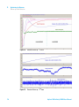
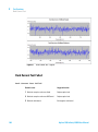
The figures below show the first two hours of a detector warm- up phase.
The lamp was turned on immediately after turn on of the detector.
Agilent 1290 Infinity II VWD User Manual
69
5
70
Optimizing the Detector
Warm up of the Detector
Figure 18
Detector Warm-up – 1st hour
Figure 19
Detector Warm-up – 2nd hour
Agilent 1290 Infinity II VWD User Manual
Agilent 1290 Infinity II VWD User Manual
6
Troubleshooting and Diagnostics
Available Tests versus Interfaces
Agilent Lab Advisor Software
72
73
Overview about the troubleshooting and diagnostic features.
Agilent Technologies
71
6
Troubleshooting and Diagnostics
Available Tests versus Interfaces
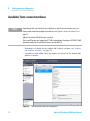
Available Tests versus Interfaces
NOTE
Depending on the used interface, the available tests and the screens/reports may vary.
Preferred tool should be the Agilent Lab Advisor, see “Agilent Lab Advisor Software” on
page 73.
Agilent Lab Advisor B.02.06 or later is required.
The Instant Pilot does not support the G7114B at introduction. If running as G1314E/F VWD
(emulation mode) the Instant Pilot firmware must be B.02.16.
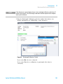
• Preferred tool should be the Agilent Lab Advisor software, see “Agilent
Lab Advisor Software” on page 73
• Screenshots used within these procedures are based on the Agilent Lab
Advisor software.
Figure 20
72
The Lab Advisor shows the available test
Agilent 1290 Infinity II VWD User Manual
Troubleshooting and Diagnostics
Agilent Lab Advisor Software
6
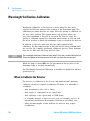
Agilent Lab Advisor Software
The Agilent Lab Advisor Software is a standalone product that can be
used with or without chromatographic data system. Agilent Lab Advisor
helps to manage the lab for high- quality chromatographic results by
providing a detailed system overview of all connected analytical
instruments with instrument status, Early Maintenance Feedback counters
(EMF), instrument configuration information, and diagnostic tests. By the
push of a button, a detailed diagnostic report can be generated. Upon
request, the user can send this report to Agilent for a significantly
improved troubleshooting and repair process.
The Agilent Lab Advisor software is available in two versions:
• Lab Advisor Basic
• Lab Advisor Advanced
Lab Advisor Basic is included with every Agilent 1200 Infinity Series and
Infinity II Series pump.
The Lab Advisor Advanced features can be unlocked by purchasing a
license key, and include real- time monitoring of instrument actuals, all
various instrument signals, and state machines. In addition, all diagnostic
test results, calibration results, and acquired signal data can be uploaded
to a shared network folder. The Review Client included in Lab Advisor
Advanced allows to load and examine the uploaded data no matter on
which instrument it was generated. This makes Data Sharing an ideal tool
for internal support groups and users who want to track the instrument
history of their analytical systems.
The optional Agilent Maintenance Wizard Add- on provides an easy- to- use,
step- by- step multimedia guide for performing preventive maintenance on
Agilent 1200 Infinity and Infinity II Series instruments.
The tests and diagnostic features that are provided by the Agilent Lab
Advisor software may differ from the descriptions in this manual. For
details, refer to the Agilent Lab Advisor software help files.
Agilent 1290 Infinity II VWD User Manual
73
6
74
Troubleshooting and Diagnostics
Agilent Lab Advisor Software
Agilent 1290 Infinity II VWD User Manual
Agilent 1290 Infinity II VWD User Manual
7
Error Information
What Are Error Messages
77
General Error Messages 78
Timeout 78
Shutdown 78
Remote Timeout 79
Lost CAN Partner 80
Leak 80
Leak Sensor Open 81
Leak Sensor Short 81
Compensation Sensor Open
Compensation Sensor Short
Fan Failed 83
Open Cover 83
ERI Messages 84
82
82
Detector Error Messages 85
UV lamp: no current 85
UV lamp: no voltage 86
Ignition Failed 86
No heater current 87
Wavelength calibration setting failed 88
Wavelength holmium check failed 89
Grating or Filter Motor Errors 90
Wavelength test failed 91
Cutoff filter doesn't decrease the light intensity at 250 nm 91
ADC Hardware Error 92
Illegal Temperature Value from Sensor on Main Board 92
Illegal Temperature Value from Sensor at Air Inlet 93
Heater at fan assembly failed 93
Agilent Technologies
75
7
Error Information
Agilent Lab Advisor Software
Heater Power At Limit
Cover Violation 94
94
This chapter describes the meaning of detector error messages, and provides
information on probable causes and suggested actions how to recover from
error conditions.
76
Agilent 1290 Infinity II VWD User Manual
Error Information
What Are Error Messages
7
What Are Error Messages
Error messages are displayed in the user interface when an electronic,
mechanical, or hydraulic (flow path) failure occurs which requires
attention before the analysis can be continued (for example, repair, or
exchange of consumables is necessary). In the event of such a failure, the
red status indicator at the front of the module is switched on, and an
entry is written into the module logbook.
If an error occurs outside a method run, other modules will not be
informed about this error. If it occurs within a method run, all connected
modules will get a notification, all LEDs get red and the run will be
stopped. Depending on the module type, this stop is implemented
differently. For example, for a pump the flow will be stopped for safety
reasons. For a detector, the lamp will stay on in order to avoid
equilibration time. Depending on the error type, the next run can only be
started, if the error has been resolved, for example liquid from a leak has
been dried. Errors for presumably single time events can be recovered by
switching on the system in the user interface.
Special handling is done in case of a leak. As a leak is a potential safety
issue and may have occurred at a different module from where it has been
observed, a leak always causes a shutdown of all modules, even outside a
method run.
In all cases, error propagation is done via the CAN bus or via an APG
remote cable (see documentation for the APG interface).
Agilent 1290 Infinity II VWD User Manual
77
7
Error Information
General Error Messages
General Error Messages
General error messages are generic to all Agilent series HPLC modules
and may show up on other modules as well.
Timeout
Error ID: 0062
The timeout threshold was exceeded.
Probable cause
Suggested actions
1 The analysis was completed successfully,
Check the logbook for the occurrence and
source of a not-ready condition. Restart the
analysis where required.
and the timeout function switched off the
module as requested.
2 A not-ready condition was present during a
sequence or multiple-injection run for a
period longer than the timeout threshold.
Check the logbook for the occurrence and
source of a not-ready condition. Restart the
analysis where required.
Shutdown
Error ID: 0063
An external instrument has generated a shutdown signal on the remote
line.
The module continually monitors the remote input connectors for status
signals. A LOW signal input on pin 4 of the remote connector generates
the error message.
78
Agilent 1290 Infinity II VWD User Manual
Error Information
General Error Messages
Probable cause
Suggested actions
1 Leak detected in another module with a
Fix the leak in the external instrument before
restarting the module.
CAN connection to the system.
2 Leak detected in an external instrument
with a remote connection to the system.
3 Shut-down in an external instrument with a
remote connection to the system.
4 The degasser failed to generate sufficient
vacuum for solvent degassing.
7
Fix the leak in the external instrument before
restarting the module.
Check external instruments for a shut-down
condition.
Check the vacuum degasser for an error
condition. Refer to the Service Manual for the
degasser or the 1260 pump that has the
degasser built-in.
Remote Timeout
Error ID: 0070
A not- ready condition is still present on the remote input. When an
analysis is started, the system expects all not- ready conditions (for
example, a not- ready condition during detector balance) to switch to run
conditions within one minute of starting the analysis. If a not- ready
condition is still present on the remote line after one minute the error
message is generated.
Probable cause
Suggested actions
1 Not-ready condition in one of the
Ensure the instrument showing the not-ready
condition is installed correctly, and is set up
correctly for analysis.
instruments connected to the remote line.
2 Defective remote cable.
Exchange the remote cable.
3 Defective components in the instrument
Check the instrument for defects (refer to the
instrument’s documentation).
showing the not-ready condition.
Agilent 1290 Infinity II VWD User Manual
79
7
Error Information
General Error Messages
Lost CAN Partner
Error ID: 0071
During an analysis, the internal synchronization or communication
between one or more of the modules in the system has failed.
The system processors continually monitor the system configuration. If one
or more of the modules is no longer recognized as being connected to the
system, the error message is generated.
Probable cause
Suggested actions
1 CAN cable disconnected.
•
Ensure all the CAN cables are connected
correctly.
•
Ensure all CAN cables are installed
correctly.
2 Defective CAN cable.
Exchange the CAN cable.
3 Defective main board in another module.
Switch off the system. Restart the system, and
determine which module or modules are not
recognized by the system.
Leak
Error ID: 0064
A leak was detected in the module.
The signals from the two temperature sensors (leak sensor and
board- mounted temperature- compensation sensor) are used by the leak
algorithm to determine whether a leak is present. When a leak occurs, the
leak sensor is cooled by the solvent. This changes the resistance of the
leak sensor which is sensed by the leak- sensor circuit on the main board.
80
Probable cause
Suggested actions
1 Loose fittings.
Ensure all fittings are tight.
2 Broken capillary.
Exchange defective capillaries.
3 Leaking flow cell.
Exchange flow cell components.
Agilent 1290 Infinity II VWD User Manual
Error Information
General Error Messages
7
Leak Sensor Open
Error ID: 0083
The leak sensor in the module has failed (open circuit).
The current through the leak sensor is dependent on temperature. A leak
is detected when solvent cools the leak sensor, causing the leak- sensor
current to change within defined limits. If the current falls outside the
lower limit, the error message is generated.
Probable cause
Suggested actions
1 Leak sensor not connected to the Power
Please contact your Agilent service
representative.
Switch board.
2 Defective leak sensor.
Please contact your Agilent service
representative.
3 Leak sensor incorrectly routed, being
Please contact your Agilent service
representative.
pinched by a metal component.
Leak Sensor Short
Error ID: 0082
The leak sensor in the module has failed (short circuit).
The current through the leak sensor is dependent on temperature. A leak
is detected when solvent cools the leak sensor, causing the leak sensor
current to change within defined limits. If the current increases above the
upper limit, the error message is generated.
Probable cause
Suggested actions
1 Defective leak sensor.
Please contact your Agilent service
representative.
2 Leak sensor incorrectly routed, being
Please contact your Agilent service
representative.
pinched by a metal component.
Agilent 1290 Infinity II VWD User Manual
81
7
Error Information
General Error Messages
Compensation Sensor Open
Error ID: 0081
The ambient- compensation sensor (NTC) on the power switch board in the
module has failed (open circuit).
The resistance across the temperature compensation sensor (NTC) on the
power switch board is dependent on ambient temperature. The change in
resistance is used by the leak circuit to compensate for ambient
temperature changes. If the resistance across the sensor increases above
the upper limit, the error message is generated.
Probable cause
Suggested actions
1 Loose connection between the power
Please contact your Agilent service
representative.
switch board and the main board
2 Defective power switch board
Please contact your Agilent service
representative.
Compensation Sensor Short
Error ID: 0080
The ambient- compensation sensor (NTC) on the power switch board in the
module has failed (open circuit).
The resistance across the temperature compensation sensor (NTC) on the
power switch board is dependent on ambient temperature. The change in
resistance is used by the leak circuit to compensate for ambient
temperature changes. If the resistance across the sensor falls below the
lower limit, the error message is generated.
Probable cause
Suggested actions
1 Defective power switch board
Please contact your Agilent service
representative.
2 Loose connection between the power
Please contact your Agilent service
representative.
switch board and the main board
82
Agilent 1290 Infinity II VWD User Manual
7
Error Information
General Error Messages
Fan Failed
Error ID: 0068
The cooling fan in the module has failed.
The hall sensor on the fan shaft is used by the main board to monitor the
fan speed. If the fan speed falls below a certain limit for a certain length
of time, the error message is generated.
This limit is given by 2 revolutions/second for longer than 5 seconds.
Depending on the module, assemblies (e.g. the lamp in the detector) are
turned off to assure that the module does not overheat inside.
Probable cause
Suggested actions
1 Fan cable disconnected.
Please contact your Agilent service representative.
2 Defective fan.
Please contact your Agilent service representative.
3 Defective main board.
Please contact your Agilent service representative.
Open Cover
Error ID: 0205
The top foam has been removed.
The sensor on the main board detects when the top foam is in place. If
the foam is removed, the fan is switched off, and the error message is
generated.
Probable cause
Suggested actions
1 The top foam was removed during
Please contact your Agilent service
representative.
operation.
2 Foam not activating the sensor.
Please contact your Agilent service
representative.
3 Defective sensor or main board.
Please contact your Agilent service
representative.
Agilent 1290 Infinity II VWD User Manual
83
7
Error Information
General Error Messages
ERI Messages
Error ID: 11120 (+5 V) , 11121 (+25 V)
ERI Messages
The ERI (Enhanced Remote Interface) provides two error events related to
over current situations on the +5 V and +24 V lines.
84
Probable cause
Suggested actions
1 The load on the ERI is too high.
Reduce the load.
Agilent 1290 Infinity II VWD User Manual
Error Information
Detector Error Messages
7
Detector Error Messages
These errors are detector specific.
UV lamp: no current
Error ID: 7450
The lamp anode current is missing. The processor continually monitors the
anode current drawn by the lamp during operation. If the anode current
falls below the lower current limit, the error message is generated.
Probable cause
Suggested actions
1 Lamp disconnected.
Ensure the lamp connector is seated firmly.
2 Top foam removed while lamp is on.
Please contact your Agilent service
representative.
3 Defective or non-Agilent lamp.
Exchange the lamp.
4 Defective main board.
Please contact your Agilent service
representative.
5 Defective power supply.
Please contact your Agilent service
representative.
Agilent 1290 Infinity II VWD User Manual
85
7
Error Information
Detector Error Messages
UV lamp: no voltage
Error ID: 7451
The lamp anode voltage is missing. The processor continually monitors the
anode voltage across the lamp during operation. If the anode voltage falls
below the lower limit, the error message is generated.
Probable cause
Suggested actions
1 Defective or non-Agilent lamp.
Exchange the lamp.
2 Defective power supply.
Please contact your Agilent service
representative.
3 Defective main board.
Please contact your Agilent service
representative.
Ignition Failed
Error ID: 7452
The lamp failed to ignite. The processor monitors the lamp current during
the ignition cycle. If the lamp current does not rise above the lower limit
within 2 – 5 s, the error message is generated.
86
Probable cause
Suggested actions
1 Lamp disconnected.
Ensure the lamp is connected.
2 Defective or non-Agilent lamp.
Exchange the lamp.
3 Defective power supply.
Please contact your Agilent service
representative.
4 Defective main board.
Please contact your Agilent service
representative.
Agilent 1290 Infinity II VWD User Manual
Error Information
Detector Error Messages
7
No heater current
Error ID: 7453
The lamp heater current in the detector is missing. During lamp ignition,
the processor monitors the heater current. If the current does not rise
above the lower limit within 1, the error message is generated.
Probable cause
Suggested actions
1 Lamp disconnected.
Ensure the lamp is connected.
2 Ignition started without the top foam in
Please contact your Agilent service
representative.
place.
3 Fan not running (permitting lamp on).
Please contact your Agilent service
representative.
4 Defective main board.
Please contact your Agilent service
representative.
5 Defective or non-Agilent lamp.
Exchange the lamp.
6 Defective power supply.
Please contact your Agilent service
representative.
Agilent 1290 Infinity II VWD User Manual
87
7
Error Information
Detector Error Messages
Wavelength calibration setting failed
Error ID: 7310
The intensity maximum was not found during wavelength calibration.
88
Calibration 0 Failed:
Zero-order calibration failed.
Calibration 1 Failed:
656 nm calibration failed.
Probable cause
Suggested actions
1 Lamp is OFF.
Switch on the lamp.
2 Incorrect flow cell installation.
Ensure the flow cell is installed correctly.
3 Flow cell contamination or air bubbles.
Clean/replace flow cell windows or remove air
bubbles.
4 Intensity too low.
Replace lamp.
5 Current step value too far from maximum.
•
Repeat the calibration.
•
Please contact your Agilent service
representative.
6 Misaligned/defective grating assembly.
Please contact your Agilent service
representative.
7 Defective main board.
Please contact your Agilent service
representative.
Agilent 1290 Infinity II VWD User Manual
Error Information
Detector Error Messages
7
Wavelength holmium check failed
Error ID: 7318
The holmium oxide test in the detector has failed. During the holmium
test, the detector moves the holmium filter into the light path, and
compares the measured absorbance maxima of the holmium oxide filter
with expected maxima. If the measured maxima are outside the limits, the
error message is generated.
Probable cause
Suggested actions
1 Misaligned/defective grating assembly.
•
Ensure the flow cell is inserted correctly,
and is free from contamination (cell
windows, buffers, and so on).
•
Run the filter-motor test to determine if the
filter motor assembly is defective. If
defective, please contact your Agilent
service representative.
•
Run the grating-motor test to determine if
the grating assembly is defective. If
defective, please contact your Agilent
service representative.
Agilent 1290 Infinity II VWD User Manual
89
7
Error Information
Detector Error Messages
Grating or Filter Motor Errors
Error ID: Grating: 7800, 7801, 7802, 7803, 7804, 7805, 7806, 7808, 7809;
Filter: 7810, 7811, 7812, 7813, 7814, 7815, 7816
The motor test has failed.
Test 0 Failed:
Filter motor.
Test 1 Failed:
Grating motor.
During the motor tests, the detector moves the motor to the end position
while monitoring the end- position sensor. If the end position is not found,
the error message is generated.
90
Probable cause
Suggested actions
1 Motor is not connected.
Please contact your Agilent service
representative.
2 Defective motor.
Please contact your Agilent service
representative.
3 Defective/missing grating or filter.
Please contact your Agilent service
representative.
4 Cable/connector defective.
Please contact your Agilent service
representative.
Agilent 1290 Infinity II VWD User Manual
Error Information
Detector Error Messages
7
Wavelength test failed
Error ID: 7890
The automatic wavelength check after lamp ignition has failed. When the
lamp is switched on, the detector waits 1 min to warm- up the lamp. Then
a check of the deuterium emission line (656 nm) via the reference diode is
performed. If the emission line is more than 3 nm away from 656 nm, the
error message is generated.
Probable cause
Suggested actions
1 Calibration incorrect.
Recalibrate the detector.
Cutoff filter doesn't decrease the light intensity at 250 nm
Error ID: 7813
The automatic filter check after lamp ignition has failed. When the lamp is
switched on, the detector moves the cutoff filter into the light path. If the
filter is functioning correctly, a decrease in lamp intensity is seen. If the
expected intensity decrease is not detected, the error message is
generated.
Probable cause
Suggested actions
1 Motor is not connected.
Please contact your Agilent service
representative.
2 Defective motor.
Please contact your Agilent service
representative.
3 Defective/missing grating or filter.
Please contact your Agilent service
representative.
4 Cable/connector defective.
Please contact your Agilent service
representative.
Agilent 1290 Infinity II VWD User Manual
91
7
Error Information
Detector Error Messages
ADC Hardware Error
Error ID: 7830, 7831
A/D- Converter hardware is defective.
Probable cause
Suggested actions
1 A/D-Converter hardware is defective.
Please contact your Agilent service
representative.
Illegal Temperature Value from Sensor on Main Board
Error ID: 1071
This temperature sensor (located on the detector main board) delivered a
value outside the allowed range. The parameter of this event equals the
measured temperature in 1/100 centigrade. As a result the temperature
control is switched off.
Probable cause
Suggested actions
1 Defective sensor or main board.
Please contact your Agilent service
representative.
2 Detector is exposed to illegal ambient
Verify that the ambient conditions are within
the allowed range.
conditions.
92
Agilent 1290 Infinity II VWD User Manual
Error Information
Detector Error Messages
7
Illegal Temperature Value from Sensor at Air Inlet
Error ID: 1072
This temperature sensor delivered a value outside the allowed range. The
parameter of this event equals the measured temperature in 1/100
centigrade. As a result the temperature control is switched off.
Probable cause
Suggested actions
1 The temperature sensor is defect.
•
Replace the cable to the main board.
•
Please contact your Agilent service
representative.
2 Detector is exposed to illegal ambient
conditions.
Verify that the ambient conditions are within
the allowed range.
Heater at fan assembly failed
Error ID: 1073
Every time the deuterium lamp or the tungsten lamp (DAD only) is
switched on or off a heater self- test is performed. If the test fails an error
event is created. As a result the temperature control is switched off.
Probable cause
Suggested actions
1 Defective connector or cable.
Please contact your Agilent service
representative.
2 Defective heater.
Please contact your Agilent service
representative.
Agilent 1290 Infinity II VWD User Manual
93
7
Error Information
Detector Error Messages
Heater Power At Limit
Error ID: 1074
The available power of the heater reached either the upper or lower limit.
This event is sent only once per run. The parameter determines which
limit has been hit:
0 means upper power limit hit (excessive ambient temperature drop).
1 means lower power limit hit (excessive ambient temperature increase).
Probable cause
Suggested actions
1 Excessive ambient temperature change.
Wait until temperature control equilibrates.
Cover Violation
Error ID: 7461
The top foam has been removed.
The sensor on the main board detects when the top foam is in place. If
the foam is removed while the lamps are on (or if an attempt is made to
switch on for example the lamps with the foam removed), the lamps are
switched off, and the error message is generated.
Probable cause
Suggested actions
1 The top foam was removed during
Please contact your Agilent service
representative.
operation.
2 Foam not activating the sensor.
94
Please contact your Agilent service
representative.
Agilent 1290 Infinity II VWD User Manual
Agilent 1290 Infinity II VWD User Manual
8
Test Functions
Introduction
96
Intensity Test 97
Intensity Test Evaluation 98
Intensity Test Failed 99
Cell Test 100
Cell Test Failed
101
Wavelength Verification-Calibration 102
When to Calibrate the Detector 102
ASTM Drift and Noise Test
Quick Noise Test
104
105
Dark Current Test 107
Dark Current Test Failed
108
Holmium Oxide Test 109
When to do the Test 109
Interpreting the Results 110
Holmium Oxide Test Failed 111
D/A Converter (DAC) Test 112
D/A converter Test Evaluation
114
Other Lab Advisor Functions 115
EMFs - Early Maintenance Feature
115
This chapter describes the detector’s built in test functions.
Agilent Technologies
95
8
Test Functions
Introduction
Introduction
All tests are described based on the Agilent Lab Advisor Software B.02.06.
Other user interfaces may not provide any test or just a few.
For details on the use of the interface refer to the interface
documentation.
The Lab Advisor shows the available test under Service & Diagnostics.
Figure 21
96
The Lab Advisor shows the available test
Agilent 1290 Infinity II VWD User Manual
Test Functions
Intensity Test
8
Intensity Test
The intensity test measures the intensity of the deuterium lamp over the
full VWD wavelength range (190 - 600 nm). The test can be used to
determine the performance of the lamp, and to check for dirty or
contaminated flow cell windows. When the test is started, the gain is set
to zero. To eliminate effects due to absorbing solvents, the test should be
done with water in the flow cell. The shape of the intensity spectrum is
primarily dependent on the lamp, grating, and diode characteristics.
Therefore, intensity spectra will differ slightly between instruments. The
figure below shows a typical intensity test spectrum.
The Intensity Test is available in Agilent Lab Advisor (preferred tool).
Agilent 1290 Infinity II VWD User Manual
97
8
Test Functions
Intensity Test
Intensity Test Evaluation
The Agilent Lab Advisor and the Instant Pilot evaluate three values
automatically and display the limits for each value, the average, the
minimum and the maximum of all data points and passed or failed for each
value.
1 Run the Intensity- Test with Agilent Lab Advisor (for further
information see Online- Help of user interface).
98
Figure 22
Intensity Test – Results
Figure 23
Intensity Test – Signal
Agilent 1290 Infinity II VWD User Manual
Test Functions
Intensity Test
8
Intensity Test Failed
Intensity Test Failed
Probable cause
Suggested actions
1 Empty flow cell
Ensure the flow cell is filled with water.
2 Flow cell windows dirty
Repeat the test with the flow cell removed. If
the test passes, exchange the flow cell
windows.
3 Optics defect
Please contact your Agilent service
representative.
4 Defective lamp or optics.
Exchange the lamp.
Agilent 1290 Infinity II VWD User Manual
99
8
Test Functions
Cell Test
Cell Test
The cell test compares the intensity of the deuterium lamp measured by
the sample and reference diodes (unfiltered and not logarithmized) when
the grating is in the zero- order position. The resulting intensity ratio
(sample:reference) is a measure of the amount of light absorbed by the
flow cell.
The test can be used to check for dirty or contaminated flow cell
windows. When the test is started, the gain is set to - 1. To eliminate
effects due to absorbing solvents, the test should be done with water in
the flow cell.
Limits: No real limit. The reason is that it depends on the
position/alignment of the reference side (beam splitter – reference slit –
reference diode). Therefore the reference side value can be higher/smaller
than the sample side value.
With a clean cell the counts for sample and reference (photocurrent) are
in the same range. If the sample side shows much lower values than the
reference side the flow cell might have a problem.
Prerequisites
100
Flush the flow cell with a flow of 1 mL/min for at least 10 minutes.
Agilent 1290 Infinity II VWD User Manual
Test Functions
Cell Test
8
1 Run the Cell- Test with Agilent Lab Advisor (for further information see
Online- Help of user interface).
Figure 24
Test – Results
Cell Test Failed
Cell Test Failed
Probable cause
Suggested actions
1 Cell contaminated
Flush flow cell
2 Cell windows are contaminated
Clean/replace cell windows
3 Mechanical problem
Check cell position
Agilent 1290 Infinity II VWD User Manual
101
8
Test Functions
Wavelength Verification-Calibration
Wavelength Verification-Calibration
Wavelength calibration of the detector is done using the zero- order
position and 656 nm emission line position of the deuterium lamp. The
calibration procedure involves two steps. First the grating is calibrated on
the zero- order position. The stepper- motor step position where the
zero- order maximum is detected is stored in the detector. Next, the
grating is calibrated against the deuterium emission- line at 656 nm, and
the motor position at which the maximum occurs is stored in the detector.
In addition to the zero- order and 656 nm (alpha- emission line)
calibration, the beta- emission line at 486 nm and the three holmium lines
are used for the complete wavelength calibration process. These holmium
lines are at 360.8 nm, 418.5 nm and 536.4 nm.
NOTE
The wavelength verification/calibration takes about 2.5 min and is disabled within the first
10 min after ignition of the lamp because initial drift may distort the measurement.
When the lamp is turned ON, the 656 nm emission line position of the
deuterium lamp is checked automatically.
The Wavelength Verification/Calibration is available in Agilent Lab Advisor
(preferred tool).
When to Calibrate the Detector
The detector is calibrated at the factory, and under normal operating
conditions should not require recalibration. However, it is advisable to
recalibrate:
• after maintenance (flow cell or lamp),
• after repair of components in the optical unit,
• after exchange of the optical unit or VWM board,
• at a regular interval, at least once per year (for example, prior to an
Operational Qualification/Performance Verification procedure), and
• when chromatographic results indicate the detector may require
recalibration.
102
Agilent 1290 Infinity II VWD User Manual
8
Test Functions
Wavelength Verification-Calibration
NOTE
If the detector was repaired (opened covers), the wavelength calibration can be done 10
minutes after lamp on. A final wavelength calibration should be repeated after complete
warm-up of the detector.
1 Run the Wavelength Calibration with the Agilent Lab Advisor (for
further information see Online- Help of user interface).
Figure 25
Wavelength Calibration - Results
If you select No, the test is aborted.
If you select Yes, the re- calibration is performed (the offset is
corrected).
Agilent 1290 Infinity II VWD User Manual
103
8
Test Functions
ASTM Drift and Noise Test
ASTM Drift and Noise Test
The ASTM Drift and Noise test determines the detector noise over a
period of 20 minutes. The test is done with HPLC- grade water flowing
through the flow cell at 1 mL/min. On completion of the test, the noise
result is displayed automatically.
1 Run the ASTM Drift and Noise Test with Agilent Lab Advisor (for
further information see Online- Help of user interface).
104
Figure 26
ASTM Drift and Noise Test – Results
Figure 27
Drift and Noise Test – Signal
Agilent 1290 Infinity II VWD User Manual
8
Test Functions
Quick Noise Test
Quick Noise Test
The noise test measures the noise of the detector, with HPLC- grade water
flowing through the flow cell at 1 mL/min, in one minute intervals over a
total of 5 minutes.
The noise of the detector is calculated by using the maximum amplitude
for all random variations of the detector signal of frequencies greater than
one cycle per hour. The noise is determined for 5 one minute intervals
and is based on the accumulated peak- to- peak noise for the intervals. At
least seven data points per cycles are used in the calculation.
The cycles in the noise determination are not overlapping.
In order to obtain reliable results, the lamp should be turned on for at
least 10 minutes prior to measurement.
1 Run the Quick Noise Test with Agilent Lab Advisor (for further
information see Online- Help of user interface).
Figure 28
Quick Noise Test – Results
Agilent 1290 Infinity II VWD User Manual
105
8
Test Functions
Quick Noise Test
Figure 29
106
Quick Noise Test – Signal
Agilent 1290 Infinity II VWD User Manual
8
Test Functions
Dark Current Test
Dark Current Test
The dark- current test measures the leakage current from the sample and
reference circuits. The test is used to check for defective sample or
reference diodes or ADC circuits which may cause non- linearity or
excessive baseline noise. During the test, the shutter is moved into the
light path. Next, the leakage current from both diodes is measured.
1 Run the Dark Current Test with the Agilent Lab Advisor (for further
information see Online- Help of user interface).
Figure 30
Dark Current Test - Results
Agilent 1290 Infinity II VWD User Manual
107
8
Test Functions
Dark Current Test
Figure 31
Dark Current Test - Signals
Dark Current Test Failed
Dark Current Test Failed
108
Probable cause
Suggested actions
1 Defective sample or reference diode.
Replace optical unit.
2 Defective sample or reference ADC board.
Replace optical unit.
3 Defective main board.
Exchange the main board.
Agilent 1290 Infinity II VWD User Manual
Test Functions
Holmium Oxide Test
8
Holmium Oxide Test
This test verifies the calibration of the detector against the three
wavelength maxima of the built- in holmium oxide filter. The test displays
the difference between the expected and measured maxima. The figure
below shows a holmium test spectrum.
The Holmium Oxide Test is available in Agilent Lab Advisor (preferred
tool).
The test uses the following holmium maxima:
• 360.8 nm
• 418.5 nm
• 536.4 nm
NOTE
See also “Declaration of Conformity for HOX2 Filter” on page 224.
When to do the Test
• after recalibration,
• as part of the Operational Qualification/Performance Verification
procedure, or
• after flow cell maintenance or repair.
Agilent 1290 Infinity II VWD User Manual
109
8
Test Functions
Holmium Oxide Test
Interpreting the Results
The test is passed successfully when all three wavelengths are within
± 1 nm of the expected value. This indicates the detector is calibrated
correctly.
1 Run the Holmium Oxide Test with the Agilent Lab Advisor (for further
information see Online- Help of user interface).
110
Figure 32
Holmium Oxide Test - Results
Figure 33
Holmium Oxide Test - Signals
Agilent 1290 Infinity II VWD User Manual
Test Functions
Holmium Oxide Test
8
Holmium Oxide Test Failed
Holmium Oxide Test Failed
Probable cause
Suggested actions
1 Detector not calibrated.
Recalibrate the detector.
2 Dirty or defective flow cell.
Repeat the test with the flow cell removed. If
the test is OK, exchange the flow cell
components.
3 Dirty or defective holmium oxide filter.
Run the holmium oxide filter test. If the test
fails, contact your Agilent service
representative.
4 Optical misalignment.
Please contact your Agilent service
representative.
Agilent 1290 Infinity II VWD User Manual
111
8
Test Functions
D/A Converter (DAC) Test
D/A Converter (DAC) Test
The detector provides analog output of chromatographic signals for use
with integrators, chart recorders or data systems. The analog signal is
converted from the digital format by the digital- analog- converter (DAC).
The DAC test is used to verify correct operation of the
digital- analog- converter by applying a digital test signal to the DAC.
The DAC outputs an analog signal of approximately 50 mV (if the zero
offset of the analog output is set to the default value of 5 %) which can be
plotted on an integrator. A continuous square wave with an amplitude of
10 µV and a frequency of approximately 1 cycle/24 seconds is applied to
the signal.
The amplitude of the square wave and the peak- to- peak noise are used to
evaluate the DAC test.
When
If the analog detector signal is noisy or missing.
Preparations
Lamp must be on for at least 10 minutes. Connect integrator, chart recorder or data system to the
detector analog output.
112
Agilent 1290 Infinity II VWD User Manual
8
Test Functions
D/A Converter (DAC) Test
Running the test with Agilent Lab Advisor
1 Run the D/A Converter Test with the Agilent Lab Advisor (for further
information see Online- Help of user interface).
Figure 34
Converter Test - Results
Figure 35
D/A Converter (DAC) Test – Example of Integrator Plot
Running the Test with Instant Pilot
The test can be started via the command line.
1 To start the test
TEST: DAC 1
Reply: RA 00000 TEST:DAC 1
2 To stop the test
TEST:DAC 0
Reply: RA 00000 TEST:DAC 0
Agilent 1290 Infinity II VWD User Manual
113
8
Test Functions
D/A Converter (DAC) Test
D/A converter Test Evaluation
Test Evaluation
The noise on the step should be less than 3 µV.
Probable cause
Suggested actions
1 Bad cable or grounding problem between
Check or replace the cable.
detector and external device.
2 Defective detector main board.
114
Please contact your Agilent service
representative.
Agilent 1290 Infinity II VWD User Manual
Test Functions
Other Lab Advisor Functions
8
Other Lab Advisor Functions
EMFs - Early Maintenance Feature
The EMFs screen allows you to view and manage the EMF counters for all
modules in all systems.
Figure 36
EMFs
Agilent 1290 Infinity II VWD User Manual
115
8
116
Test Functions
Other Lab Advisor Functions
Agilent 1290 Infinity II VWD User Manual
Agilent 1290 Infinity II VWD User Manual
9
Maintenance
Introduction to Maintenance
Warnings and Cautions
118
Overview of Maintenance
Cleaning the Module
118
120
121
Remove and Install the Doors
122
Replace the Deuterium Lamp
123
Replace the Flow Cell / Cuvette Holder
Repairing the Flow Cells
Using the Cuvette Holder
Correcting Leaks
126
128
131
133
Replacing Leak Handling System Parts
Replace the Module Firmware
135
136
This chapter provides general information on maintenance of the detector.
Agilent Technologies
117
9
Maintenance
Introduction to Maintenance
Introduction to Maintenance
The module is designed for easy maintenance. Maintenance can be done
from the front with module in place in the system stack.
NOTE
There are no serviceable parts inside.
Do not open the module.
Warnings and Cautions
WA R N I N G
Toxic, flammable and hazardous solvents, samples and reagents
The handling of solvents, samples and reagents can hold health and safety risks.
➔ When working with these substances observe appropriate safety procedures (for
example by wearing goggles, safety gloves and protective clothing) as described in
the material handling and safety data sheet supplied by the vendor, and follow good
laboratory practice.
➔ The volume of substances should be reduced to the minimum required for the
analysis.
➔ Do not operate the instrument in an explosive atmosphere.
WA R N I N G
Eye damage by detector light
Eye damage may result from directly viewing the UV-light produced by the lamp of
the optical system used in this product.
➔ Always turn the lamp of the optical system off before removing it.
118
Agilent 1290 Infinity II VWD User Manual
9
Maintenance
Warnings and Cautions
WA R N I N G
Electrical shock
Repair work at the module can lead to personal injuries, e.g. shock hazard, when the
cover is opened.
➔ Do not remove the cover of the module.
➔ Only certified persons are authorized to carry out repairs inside the module.
WA R N I N G
Personal injury or damage to the product
Agilent is not responsible for any damages caused, in whole or in part, by improper
use of the products, unauthorized alterations, adjustments or modifications to the
products, failure to comply with procedures in Agilent product user guides, or use of
the products in violation of applicable laws, rules or regulations.
➔ Use your Agilent products only in the manner described in the Agilent product user
guides.
CAUTION
Safety standards for external equipment
➔ If you connect external equipment to the instrument, make sure that you only use
accessory units tested and approved according to the safety standards appropriate
for the type of external equipment.
Agilent 1290 Infinity II VWD User Manual
119
9
Maintenance
Overview of Maintenance
Overview of Maintenance
The following pages describe maintenance (simple repairs) of the detector
that can be carried out without opening the main cover.
Table 10
Simple Repairs
Procedures
Typical Frequency
Notes
Deuterium lamp
exchange
If noise and/or drift exceeds your application limits or
lamp does not ignite.
A wavelength calibration test and an
intensity test should be performed after
replacement.
Flow cell exchange
If application requires a different flow cell type.
A wavelength calibration test should be
performed after replacement.
Cleaning flow cell
parts cleaning or
exchange
If leaking or if intensity drops due to contaminated flow
cell windows.
A pressure tightness test should be
done after repair.
Leak sensor drying
If leak has occurred.
Check for leaks.
Leak handling system
replacement
If broken or corroded.
Check for leaks.
120
Agilent 1290 Infinity II VWD User Manual
9
Maintenance
Cleaning the Module
Cleaning the Module
To keep the module case clean, use a soft cloth slightly dampened with
water, or a solution of water and mild detergent.
WA R N I N G
Liquid dripping into the electronic compartment of your module can cause shock
hazard and damage the module
➔ Do not use an excessively damp cloth during cleaning.
➔ Drain all solvent lines before opening any connections in the flow path.
Agilent 1290 Infinity II VWD User Manual
121
9
Maintenance
Remove and Install the Doors
Remove and Install the Doors
Parts required
NOTE
p/n
Description
5067-5737
Door left
5067-5736
Door right
The figures shown in this procedure exemplarily show the Infinity II Multisampler module.
The principle of how to remove and/or install doors works in the same way for all Infinity II
modules.
1 Press the release buttons and pull the front door out.
2 For the Installation of the front door. Insert the hinges
into their guides and move the door in until the release
buttons click into their final position.
122
Agilent 1290 Infinity II VWD User Manual
9
Maintenance
Replace the Deuterium Lamp
Replace the Deuterium Lamp
When
Tools required
If noise or drift exceeds application limits or lamp does not ignite.
Description
Screwdriver, Pozidriv #1 PT3
Parts required
Preparations
WA R N I N G
#
p/n
Description
1
G1314-60101
Deuterium lamp (with RFID tag)
Turn the lamp OFF.
Injury by touching hot lamp
If the detector has been in use, the lamp may be hot.
➔ If so, wait for lamp to cool down.
WA R N I N G
Injury by sharp metal edges
➔ Be careful when touching the RFI sheet metal at the rear of the fan. There are sharp
edges.
CAUTION
Electronic boards and components are sensitive to electrostatic discharge (ESD).
➔ To prevent accidental electrostatic discharge when coming into contact with
components inside the instrument, touch one of the metal housing panels at the
front of the instrument.
Agilent 1290 Infinity II VWD User Manual
123
9
Maintenance
Replace the Deuterium Lamp
1 Open the doors.
2 Locate the heater fan cover.
3 Unscrew the fan cover (1.) and remove it (2.).
4 Unplug the lamp connector.
&#
'#
5 Unscrew the two lamp screws (Pozidriv).
6 Remove the lamp and place it on a clean place.
NOTE
Do not touch the glass bulb with your fingers. It may
reduce the light output.
124
Agilent 1290 Infinity II VWD User Manual
Maintenance
Replace the Deuterium Lamp
7 Insert the lamp (RFID tag on top) (1.) and fix the screws
9
8 Reconnect the connector.
(2.).
'#
&#
9 Replace the fan cover (1.) and fix its screw (2.).
10 Close the doors.
'#
&#
Next Steps:
11 Reset the lamp counter as described in the User Interface documentation (required for non-RFID tag lamps only).
12 Turn the lamp ON and give the lamp more than 10 minutes to warm-up.
13 Perform a Wavelength Re-calibration after lamp warm-up.
NOTE
After lamp on, the detector requires a warm-up time of 60 minutes. No measurements
should be performed during this time.
Agilent 1290 Infinity II VWD User Manual
125
9
Maintenance
Replace the Flow Cell / Cuvette Holder
Replace the Flow Cell / Cuvette Holder
When
Tools required
If application needs a different type of flow cell or the flow cell needs repair.
Description
Wrench, 1/4 inch
for capillary connections
Parts required
#
Description
1
Flow cell
For flow cell details see
• “Standard Flow Cell 10 mm / 14 µL” on page 142
• “Micro Flow Cell 3 mm / 2 µL” on page 144
• “Semi-micro Flow Cell 6 mm / 5 µL” on page 146
• “High Pressure Flow Cell 10 mm / 14 µL” on page 148
Preparations
1 Open the doors.
Turn the lamp OFF.
2 Disconnect the inlet capillary and outlet tubing from the
flow cell.
&#
&#
'#
'#
126
Agilent 1290 Infinity II VWD User Manual
Maintenance
Replace the Flow Cell / Cuvette Holder
3 Unscrew the two thumb screws.
4 Pull the flow cell out of its location.
5 Insert the flow cell into its location and press it in in the
6 Fix the two thumb screws parallel and tight.
9
center of the flow cell.
7 Reconnect the inlet capillary and the outlet tubing.
'#
8 Close the doors.
'#
&#
&#
9 Perform a Wavelength Verification-Calibration to check the correct position of the flow cell/cuvette holder.
Agilent 1290 Infinity II VWD User Manual
127
9
Maintenance
Repairing the Flow Cells
Repairing the Flow Cells
Parts required
#
Description
1
Flow cell
For details on flow cells see
• “Standard Flow Cell 10 mm / 14 µL” on page 142
• “Micro Flow Cell 3 mm / 2 µL” on page 144
• “Semi-micro Flow Cell 6 mm / 5 µL” on page 146
• “High Pressure Flow Cell 10 mm / 14 µL” on page 148
NOTE
128
The shown cell parts will differ depending upon the flow cell type. For detailed parts
schematics, refer to above mentioned pages.
Agilent 1290 Infinity II VWD User Manual
9
Maintenance
Repairing the Flow Cells
&
&"8ZaahXgZl
'"8dc^XVaheg^c\h
("G^c\&E::@
)"<Vh`Zi&hbVaa]daZ
*"L^cYdlFjVgio
+"<Vh`Zi'aVg\Z]daZ
,"G^c\'E::@
-"G;>9iV\
'
,
*
+
)
*
(
'
&
Figure 37
Standard Flow Cell
1 Disassembling the Flow Cell.
a Unscrew the cell screw using a 4- mm hexagonal wrench.
b Remove the SST rings using a pair of tweezers.
CAUTION
Scratched window surfaces by tweezers
Window surfaces can easily be scratched by using tweezers for removing the
windows.
➔ Do not use tweezers to remove windows
c Use adhesive tape to remove the peek ring, the window and the
gasket.
d Repeat step a through step c for the other window (keep the parts
separate - otherwise they could be mixed!).
Agilent 1290 Infinity II VWD User Manual
129
9
Maintenance
Repairing the Flow Cells
2 Cleaning the Flow Cell Parts
a Pour isopropanol into the cell hole and wipe clean with a piece of
lint- free cloth.
b Clean the windows with ethanol or methanol. Dry it with a piece of
lint- free cloth.
NOTE
Always use new gaskets.
3 Reassembling the Flow Cell
a Hold the flow cell cassette horizontally and place gasket in position.
Ensure both cell holes can be seen through the holes of gasket.
NOTE
The semi-micro #1 and #2 gaskets (items 6 and 7, “Semi-micro Flow Cell 6 mm / 5 µL” on
page 146) look very similar. Do not mix them up.
b Place the window on gasket.
c Place the peek ring on the window.
d Insert the conical springs. Make sure the conical springs point
towards the window. Otherwise tightening the cell screw might break
the window.
Conical springs
Ring - Window - Gasket - Arrangement
Figure 38
Orientation of conical springs
e Screw the cell screw into the flow cell and tighten the screw.
4 Repeat the procedure for the other cell side.
5 Reconnect the capillaries.
6 Perform a leak test. If OK, insert the flow cell.
7 Perform “Wavelength Verification- Calibration” on page 102 to check the
correct positioning of the flow cell.
8 Replace the front cover.
130
Agilent 1290 Infinity II VWD User Manual
9
Maintenance
Using the Cuvette Holder
Using the Cuvette Holder
This cuvette holder can be placed instead of a flow cell in the variable
wavelength detector. Standard cuvettes with standards in it, for example,
National Institute of Standards & Technology (NIST) holmium oxide
solution standard, can be fixed in it.
This can be used for wavelength verifications.
When
If your own standard should be used to checkout the instrument.
Parts required
#
p/n
Description
1
G1314-60200
Cuvette Holder
1
Preparations
•
•
Cuvette with the “standard”, e.g. NIST certified holmium oxide sample
Remove the normal flow cell.
Have cuvette with standard available.
Agilent 1290 Infinity II VWD User Manual
131
9
Maintenance
Using the Cuvette Holder
1 Locate the cuvette holder on the desk.
2 Unscrew the bracket.
3 Insert the cuvette with the sample into the holder. The
4 Replace the bracket and fix the cuvette.
clear side of the cuvette must be visible.
A^\]ieVi]
8aZVgh^YZ
Next Steps:
5 Install the cuvette holder in the instrument.
6 Perform your Wavelength Verification/Calibration (see “Wavelength Verification-Calibration” on page 102) to check the
correct position of the cuvette holder.
132
Agilent 1290 Infinity II VWD User Manual
9
Maintenance
Correcting Leaks
Correcting Leaks
;adlXZaaVgZVP'R
AZV`hZchdgVgZVP&R
Figure 39
Correcting leaks
When
If a leakage has occurred in the flow cell area or at the capillary connections.
Tools required
Description
Tissue
Wrench, 1/4 inch
for capillary connections
1 Open the doors.
2 Use tissue to dry the leak sensor area [1].
3 Observe the capillary connections and the flow cell area [2] for leaks
and correct, if required.
Agilent 1290 Infinity II VWD User Manual
133
9
Maintenance
Correcting Leaks
4 Close the doors.
134
Agilent 1290 Infinity II VWD User Manual
9
Maintenance
Replacing Leak Handling System Parts
Replacing Leak Handling System Parts
Parts required
Preparations
p/n
Description
5043-0856
Leak Adapter
5063-6527
Tubing assembly, i.d. 6 mm, o.d. 9 mm, 1.2 m (to waste)
Open or remove the doors
1 Locate the Leak Adapter [1] and Tubing [2]
Next Steps:
2 Press the Leak Adapter [1] down and remove it together
with the tubing.
&
3 Install the Leak Adapter by pressing it into the Main
Cover.
'
4 Insert the Tubing [2] (ca. 85 mm required for
replacement) between Leak Adapter outlet and Leak Pan.
5 Insert/close the doors.
Agilent 1290 Infinity II VWD User Manual
135
9
Maintenance
Replace the Module Firmware
Replace the Module Firmware
When
The installation of newer firmware might be necessary
• if a newer version solves problems of older versions or
• to keep all systems on the same (validated) revision.
The installation of older firmware might be necessary
• to keep all systems on the same (validated) revision or
• if a new module with newer firmware is added to a system or
• if third party control software requires a special version.
Tools required
Description
Agilent Lab Advisor software
OR
Parts required
Preparations
Instant Pilot G4208A
(only if supported by module)
#
Description
1
Firmware, tools and documentation from Agilent web site
Read update documentation provided with the Firmware Update Tool.
To upgrade/downgrade the module’s firmware carry out the following
steps:
1 Download the required module firmware, the latest LAN/USB FW
Update Tool and the documentation from the Agilent web.
http://www.chem.agilent.com/_layouts/agilent/downloadFirmware.aspx?whid=69761
2 For loading the firmware into the module follow the instructions in the
documentation.
136
Agilent 1290 Infinity II VWD User Manual
Maintenance
Replace the Module Firmware
9
Module Specific Information
Table 11
Module Specific Information (G7114B)
G7114B
Initial firmware
B.06.70
Compatibility with 1100 / 1200 series modules
When using the G7114B in a system, all other
modules must have firmware from set 6.50 or
above (main and resident). Otherwise the
communication will not work.
Conversion / emulation
Possible via Lab Advisor software: G1314E/F.
Agilent 1290 Infinity II VWD User Manual
137
9
138
Maintenance
Replace the Module Firmware
Agilent 1290 Infinity II VWD User Manual
Agilent 1290 Infinity II VWD User Manual
10
Parts and Materials for Maintenance
Overview of Maintenance Parts
140
Standard Flow Cell 10 mm / 14 µL
Micro Flow Cell 3 mm / 2 µL
142
144
Semi-micro Flow Cell 6 mm / 5 µL
146
High Pressure Flow Cell 10 mm / 14 µL
Cuvette Holder
Accessory Kit
148
150
151
This chapter provides information on parts for maintenance.
Agilent Technologies
139
10 Parts and Materials for Maintenance
Overview of Maintenance Parts
Overview of Maintenance Parts
Figure 40
140
Overview of maintenance parts
Agilent 1290 Infinity II VWD User Manual
Parts and Materials for Maintenance
Overview of Maintenance Parts
Item
p/n
Description
1
G1314-60101
Deuterium lamp (with RFID tag)
2
G1314-60186
Standard flow cell 10 mm, 14 µL, 40 bar
(with RFID tag)
2
G1314-60187
Micro flow cell 3 mm, 2 µL, 120 bar
(with RFID tag)
2
G1314-60183
Semi-micro flow cell 6 mm, 5 µL
(with RFID tag)
2
G1314-60182
High pressure flow cell 10 mm, 14 µL, 400 bar
(with RFID tag)
2
G1314-60023
Prep flow cell 0.06 mm
2
G1314-60025
Prep flow cell 0.3 mm
2
G1314-60024
Prep flow cell 3 mm
3
5043-0856
Leak Adapter
4
5063-6527
Tubing assembly, i.d. 6 mm, o.d. 9 mm, 1.2 m (to waste)
5062-8535
Waste accessory kit
(Flow Cell to Waste)
5
5067-5737
Door left
6
5067-5736
Door right
7
5043-1013
Tubing Clip
Agilent 1290 Infinity II VWD User Manual
10
141
10 Parts and Materials for Maintenance
Standard Flow Cell 10 mm / 14 µL
Standard Flow Cell 10 mm / 14 µL
Item
142
p/n
Description
G1314-60186
Standard flow cell 10 mm, 14 µL, 40 bar
(with RFID tag)
5062-8522
Capillary column - detector PEEK 600 mm lg, 0.17 mm i.d., 1/16 inch
o.d.
G1314-65061
Cell Repair Kit, includes 2x Gasket #1, 2x Gasket #2, 2x Window
Quartz
1
G1314-65062
Cell screw kit
2
79853-29100
Conical spring kit, 10/pk
3
G1314-65066
Ring #2 kit (IN small hole, i.d. 1 mm) PEEK, 2/pk
4
G1314-65064
Gaskets #2 IN (small hole i.d. 1 mm), KAPTON 10/pk
5
79853-68742
Window quartz kit, 2/pk
6
G1314-65063
Gasket #1 kit (OUT large hole, i.d. 2.4 mm) KAPTON, 2/pk
7
G1314-65065
Ring #1 kit (OUT large hole, i.d. 2.4 mm) PEEK, 2/pk
8
G1314-44010
Clip for RFI ID tag
9
0515-4780
Screw for Clip, M2.2, 4.5 mm long
Agilent 1290 Infinity II VWD User Manual
Parts and Materials for Maintenance
Standard Flow Cell 10 mm / 14 µL
&
.
'(m
&8ZaahXgZl
10
,
'8dc^XVaheg^c\h
*
(G^c\'>C
+
)<Vh`Zi'>C
*FjVgiol^cYdl
)
*
+<Vh`Zi&DJI
(
,G^c\&DJI
'(m
-G;>98a^e
&
.HXgZl
Figure 41
Standard Flow Cell
Agilent 1290 Infinity II VWD User Manual
143
10 Parts and Materials for Maintenance
Micro Flow Cell 3 mm / 2 µL
Micro Flow Cell 3 mm / 2 µL
Item
144
p/n
Description
G1314-60187
Micro flow cell 3 mm, 2 µL, 120 bar
(with RFID tag)
5021-1823
Capillary column – detector SST 400 mm lg, 0.12 mm i.d.
1
79883-22402
Window screw
2
5062-8553
Washer kit (10/pk)
3
79883-28801
Compression washer
4
79883-22301
Window holder
5
1000-0488
Quartz window
6
G1315-68710
Gasket FRONT (PTFE), 1.3 mm hole, inlet side (12/pk)
7
79883-68702
Gasket BACK (PTFE), 1.8 mm hole, outlet side (12/pk)
8
G1314-44010
Clip for RFI ID tag
9
0515-4780
Screw for Clip, M2.2, 4.5 mm long
G1314-87301
Capillary IN (0.12 mm, 310 mm lg)
G1314-87302
Capillary OUT (0.17 mm, 120 mm lg)
G1315-68713
Cell repair kit semi-micro, includes window screw kit, Gasket Kit
BACK, Gasket Kit FRONT and 4 mm hexagonal wrench
79883-68703
Window screw kit, includes 2 quartz windows, 2 compression
washers, 2 window holders, 2 window screws and 10 washers
Agilent 1290 Infinity II VWD User Manual
Parts and Materials for Maintenance
Micro Flow Cell 3 mm / 2 µL
10
1
1 - Window screw
9
2 (5x)
3
2 - Washers
8
4
5
3 - Compression washer
7
4 - Window holder
5 - Quartz window
6
6 - Gasket front
5
7 - Gasket back
4
3
2 (5x)
8 - RFID clip
1
9 - Screw
Figure 42
Micro Flow Cell
Agilent 1290 Infinity II VWD User Manual
145
10 Parts and Materials for Maintenance
Semi-micro Flow Cell 6 mm / 5 µL
Semi-micro Flow Cell 6 mm / 5 µL
NOTE
The semi-micro #1 and #2 gaskets (items 6 and 7) look very similar. Do not mix them up.
Item
p/n
Description
G1314-60183
Semi-micro flow cell 6 mm, 5 µL
(with RFID tag)
5021-1823
Capillary column – detector SST 400 mm lg, 0.12 mm i.d.
G1314-20047
Cell screw
G1314-65056
Semi-micro cell kit, includes two quartz windows, one gasket #1,
one #2 and two PTFE gaskets.
2
79853-29100
Conical spring kit, 10/pk
3
79853-22500
Ring SST, 2/pk
4
79853-68743
PTFE gasket (round hole i.d. 2.5 mm, o.d. 8 mm), (10/pk)
5
79853-68742
Window quartz kit, 2/pk
1
146
6
Semi-micro #1 gasket (long hole 1.5 x 3.5 mm), PTFE
7
Semi-micro #2 gasket (long hole 2 x 4 mm), PTFE
8
G1314-44010
Clip for RFI ID tag
9
0515-4780
Screw for Clip, M2.2, 4.5 mm long
Agilent 1290 Infinity II VWD User Manual
Parts and Materials for Maintenance
Semi-micro Flow Cell 6 mm / 5 µL
1
9
2 (3x)
1 - Cell screw
3
2 - Conical springs
10
8
4
5
3 - Ring SST
7
4 - PTFE gasket
5 - Quartz window
6
6 - Semi-micro gasket #1
5
4
3
2 (3x)
7 - Semi-micro gasket #2
1
8 - Clip for RFI ID tag
9 - Screw for clip
Figure 43
Semi-micro Flow Cell
Agilent 1290 Infinity II VWD User Manual
147
10 Parts and Materials for Maintenance
High Pressure Flow Cell 10 mm / 14 µL
High Pressure Flow Cell 10 mm / 14 µL
Item
1
148
p/n
Description
G1314-60182
High pressure flow cell 10 mm, 14 µL, 400 bar
(with RFID tag)
G1315-87311
Capillary ST 0.17 mm x 380 mm S/S
G1314-20047
Cell screw
G1314-65054
Cell kit Agilent, comprises: two windows, two KAPTON gaskets and
two PEEK rings
2
Ring PEEK kit
3
Window quartz kit
4
Gasket kit, KAPTON
5
G1314-44010
Clip for RFI ID tag
6
0515-4780
Screw for Clip, M2.2, 4.5 mm long
Agilent 1290 Infinity II VWD User Manual
Parts and Materials for Maintenance
High Pressure Flow Cell 10 mm / 14 µL
10
6
1 - Cell screw
1
5
2
3
2 - Ring PEEK
4
3 - Quartz window
4 - Gasket KAPTON
5 - RFID Clip
4
3
6 - Screw
2
1
Figure 44
High Pressure Flow Cell
Agilent 1290 Infinity II VWD User Manual
149
10 Parts and Materials for Maintenance
Cuvette Holder
Cuvette Holder
For information the use of the cuvette holder, refer to “Using the Cuvette
Holder” on page 131.
p/n
Description
G1314-60200
Cuvette Holder
Figure 45
150
Cuvette Holder
Agilent 1290 Infinity II VWD User Manual
Parts and Materials for Maintenance
Accessory Kit
10
Accessory Kit
Accessory kit (G7114- 68755) contains some accessories and tools needed
for installation and repair of the module.
p/n
Description
5062-8535
Waste accessory kit
5063-6527
Tubing assembly, i.d. 6 mm, o.d. 9 mm, 1.2 m (to waste)
(see item 4 in Figure 40 on page 140)
5181-1516
CAN cable, Agilent module to module, 0.5 m
5500-1155
Tube Connector, 90 degree, ID 6.4
5043-1013
Tubing Clip
(see item 7 in Figure 40 on page 140)
0100-1516
Fitting male PEEK, 2/pk
Agilent 1290 Infinity II VWD User Manual
151
10 Parts and Materials for Maintenance
Accessory Kit
152
Agilent 1290 Infinity II VWD User Manual
Agilent 1290 Infinity II VWD User Manual
11
Identifying Cables
Cable Overview
154
Analog Cables
156
Remote Cables
158
CAN/LAN Cables
RS-232 Cables
USB Cables
162
163
164
This chapter provides information on cables used with the Agilent 1200 Infinity
Series modules.
Agilent Technologies
153
11 Identifying Cables
Cable Overview
Cable Overview
NOTE
Never use cables other than the ones supplied by Agilent Technologies to ensure proper
functionality and compliance with safety or EMC regulations.
Analog cables
p/n
Description
35900-60750
Agilent 35900A A/D converter
01046-60105
Analog cable (BNC to general purpose, spade lugs)
p/n
Description
5188-8029
ERI
to general purpose
5188-8044
Remote Cable ERI – ERI
5188-8045
Remote Cable APG – ERI
5061-3378
Remote Cable
to 35900 A/D converter
01046-60201
Agilent module to general purpose
p/n
Description
5181-1516
CAN cable, Agilent module to module, 0.5 m
5181-1519
CAN cable, Agilent module to module, 1 m
Remote cables
CAN cables
154
Agilent 1290 Infinity II VWD User Manual
Identifying Cables
Cable Overview
11
LAN cables
RS-232 cables
(not for FUSION
board)
p/n
Description
5023-0203
Cross-over network cable, shielded, 3 m (for point to point
connection)
5023-0202
Twisted pair network cable, shielded, 7 m (for point to point
connection)
p/n
Description
G1530-60600
RS-232 cable, 2 m
RS232-61601
RS-232 cable, 2.5 m
Instrument to PC, 9-to-9 pin (female). This cable has special pin-out,
and is not compatible with connecting printers and plotters. It's also
called "Null Modem Cable" with full handshaking where the wiring
is made between pins 1-1, 2-3, 3-2, 4-6, 5-5, 6-4, 7-8, 8-7, 9-9.
5181-1561
RS-232 cable, 8 m
p/n
Description
5188-8050
USB A M-USB Mini B 3 m (PC-Module)
5188-8049
USB A F-USB Mini B M OTG (Module to Flash Drive)
USB cables
Agilent 1290 Infinity II VWD User Manual
155
11 Identifying Cables
Analog Cables
Analog Cables
One end of these cables provides a BNC connector to be connected to
Agilent modules. The other end depends on the instrument to which
connection is being made.
Agilent Module to 35900 A/D converters
p/n 35900-60750
35900
Pin Agilent
module
1
156
Signal Name
Not connected
2
Shield
Analog -
3
Center
Analog +
Agilent 1290 Infinity II VWD User Manual
Identifying Cables
Analog Cables
11
Agilent Module to BNC Connector
p/n 8120-1840
Pin BNC
Pin Agilent
module
Signal Name
Shield
Shield
Analog -
Center
Center
Analog +
Pin Agilent
module
Signal Name
Agilent Module to General Purpose
p/n 01046-60105
Pin
1
Agilent 1290 Infinity II VWD User Manual
Not connected
2
Black
Analog -
3
Red
Analog +
157
11 Identifying Cables
Remote Cables
Remote Cables
ERI (Enhanced Remote Interface)
5188- 8029 ERI to general purpose
p/n 5188-8029
pin
Enhanced Remote
Classic Remote
1
IO1
START REQUEST
2
IO2
STOP
3
IO3
READY
4
IO4
POWER ON
5
IO5
NOT USED
6
IO6
SHUT DOWN
7
IO7
START
8
IO8
PREPARE
9
1wire DATA
10
DGND
11
+5V ERI out
12
PGND
13
PGND
14
+24V ERI out
15
+24V ERI out
5188- 8044 ERI to ERI (Connector D_Subminiature 15 pin)
158
Agilent 1290 Infinity II VWD User Manual
Identifying Cables
Remote Cables
Table 12
11
5188-8044 ERI to ERI
p/n 5188-8044
Pin (ERI)
Signal
Pin (ERI)
10
GND
10
1
Start Request
1
2
Stop
2
3
Ready
3
5
Power on
5
4
Future
4
6
Shut Down
6
7
Start
7
8
Prepare
8
Ground
Connection
Cable Shielding
NC
5188- 8045 ERI to APG (Connector D_Subminiature 15 pin (ERI),
Connector D_Subminiature 9 pin (APG))
p/n 5188-8045
Agilent 1290 Infinity II VWD User Manual
Pin (ERI)
Signal
Pin (APG)
10
GND
1
1
Start Request
9
2
Stop
8
3
Ready
7
5
Power on
6
4
Future
5
6
Shut Down
4
7
Start
3
8
Prepare
2
Ground
Connection
Cable Shielding
NC
159
11 Identifying Cables
Remote Cables
One end of these cables provides a Agilent Technologies APG (Analytical
Products Group) remote connector to be connected to Agilent modules.
The other end depends on the instrument to be connected to.
Agilent Module to Agilent 35900 A/D Converters
p/n 5061-3378
160
Pin 35900
A/D
Pin Agilent
module
Signal Name
Active
(TTL)
1 - White
1 - White
Digital ground
2 - Brown
2 - Brown
Prepare run
Low
3 - Gray
3 - Gray
Start
Low
4 - Blue
4 - Blue
Shut down
Low
5 - Pink
5 - Pink
Not
connected
6 - Yellow
6 - Yellow
Power on
High
7 - Red
7 - Red
Ready
High
8 - Green
8 - Green
Stop
Low
9 - Black
9 - Black
Start request
Low
Agilent 1290 Infinity II VWD User Manual
Identifying Cables
Remote Cables
11
Agilent Module to General Purpose
p/n 01046-60201
Agilent 1290 Infinity II VWD User Manual
Wire Color
Pin Agilent
module
Signal Name
Active
(TTL)
White
1
Digital ground
Brown
2
Prepare run
Low
Gray
3
Start
Low
Blue
4
Shut down
Low
Pink
5
Not
connected
Yellow
6
Power on
High
Red
7
Ready
High
Green
8
Stop
Low
Black
9
Start request
Low
161
11 Identifying Cables
CAN/LAN Cables
CAN/LAN Cables
Both ends of this cable provide a modular plug to be connected to
Agilent modules CAN or LAN connectors.
CAN Cables
p/n
Description
5181-1516
CAN cable, Agilent module to module, 0.5 m
5181-1519
CAN cable, Agilent module to module, 1 m
LAN Cables
162
p/n
Description
5023-0203
Cross-over network cable, shielded, 3 m (for point to point
connection)
5023-0202
Twisted pair network cable, shielded, 7 m (for point to point
connection)
Agilent 1290 Infinity II VWD User Manual
Identifying Cables
RS-232 Cables
11
RS-232 Cables
p/n
Description
G1530-60600
RS-232 cable, 2 m
RS232-61601
RS-232 cable, 2.5 m
Instrument to PC, 9-to-9 pin (female). This cable has special pin-out,
and is not compatible with connecting printers and plotters. It's also
called "Null Modem Cable" with full handshaking where the wiring
is made between pins 1-1, 2-3, 3-2, 4-6, 5-5, 6-4, 7-8, 8-7, 9-9.
5181-1561
RS-232 cable, 8 m
Agilent 1290 Infinity II VWD User Manual
163
11 Identifying Cables
USB Cables
USB Cables
To connect a USB Flash Drive use a USB OTG cable with Mini- B plug and
A socket.
164
p/n
Description
5188-8050
USB A M-USB Mini B 3 m (PC-Module)
5188-8049
USB A F-USB Mini B M OTG (Module to Flash Drive)
Agilent 1290 Infinity II VWD User Manual
Agilent 1290 Infinity II VWD User Manual
12
Hardware Information
Firmware Description
166
Electrical Connections 169
Rear View of the Module 170
Information on Instrument Serial Number
Interfaces 172
Overview Interfaces 173
ERI (Enhanced Remote Interface)
USB (Universal Serial Bus) 178
Setting the 6-bit Configuration Switch
Special Settings 181
Instrument Layout
170
176
179
183
Early Maintenance Feedback
184
This chapter describes the detector in more detail on hardware and electronics.
Agilent Technologies
165
12 Hardware Information
Firmware Description
Firmware Description
The firmware of the instrument consists of two independent sections:
• a non- instrument specific section, called resident system
• an instrument specific section, called main system
Resident System
This resident section of the firmware is identical for all Agilent
1100/1200/1220/1260/1290 series modules. Its properties are:
• the complete communication capabilities (CAN, LAN, USB and RS232C)
• memory management
• ability to update the firmware of the 'main system'
Main System
Its properties are:
• the complete communication capabilities (CAN, LAN, USB and RS232C)
• memory management
• ability to update the firmware of the 'resident system'
In addition the main system comprises the instrument functions that are
divided into common functions like
• run synchronization through APG remote,
• error handling,
• diagnostic functions,
• or module specific functions like
• internal events such as lamp control, filter movements,
• raw data collection and conversion to absorbance.
166
Agilent 1290 Infinity II VWD User Manual
Hardware Information
Firmware Description
12
Firmware Updates
Firmware updates can be done using the following tools (latest version
should be used):
• Agilent Lab Advisor software with files on the hard disk (*)
• Firmware Update Tool with local files on the hard disk (*)
• Instant Pilot (G4208A) with files on a USB Flash Disk
(*)
Required tools, firmware and documentation are available from the
Agilent web:
http://www.chem.agilent.com/_layouts/agilent/downloadFirmware.aspx?whid=69761
The file naming conventions are:
PPPP_RVVV_XXX.dlb, where
PPPP is the product number, for example, 1315B for the G1315B DAD,
R the firmware revision, for example, A for G1315B or B for the G1315C
DAD,
VVV is the revision number, for example 650 is revision 6.50,
XXX is the build number of the firmware.
For instructions on firmware updates refer to section Replacing Firmware
in chapter "Maintenance" or use the documentation provided with the
Firmware Update Tools.
NOTE
Update of main system can be done in the resident system only. Update of the resident
system can be done in the main system only.
Main and resident firmware must be from the same set.
Agilent 1290 Infinity II VWD User Manual
167
12 Hardware Information
Firmware Description
BV^c;LjeYViZ
BV^cHnhiZb
GZh^YZciHnhiZb
GZh^YZci;LJeYViZ
Figure 46
NOTE
Firmware Update Mechanism
Some modules are limited in downgrading due to their main board version or their initial
firmware revision. For example, a G1315C DAD SL cannot be downgraded below firmware
revision B.01.02 or to a A.xx.xx.
Some modules can be re-branded (e.g. G1314C to G1314B) to allow operation in specific
control software environments. In this case the feature set of the target type are use and
the feature set of the original are lost. After re-branding (e.g. from G1314B to G1314C), the
original feature set is available again.
All these specific informations are described in the documentation provided with the
firmware update tools.
The firmware update tools, firmware and documentation are available
from the Agilent web.
• http://www.chem.agilent.com/_layouts/agilent/downloadFirmware.aspx?whid=69761
168
Agilent 1290 Infinity II VWD User Manual
12
Hardware Information
Electrical Connections
Electrical Connections
• The CAN bus is a serial bus with high- speed data transfer. The two
connectors for the CAN bus are used for internal module data transfer
and synchronization.
• One analog output provides signals for integrators or data handling
systems.
• The ERI/REMOTE connector may be used in combination with other
analytical instruments from Agilent Technologies if you want to use
features such as start, stop, common shutdown, prepare, and so on.
• With the appropriate software, the LAN connector may be used to
control the module from a computer through a LAN connection. This
connector is activated and can be configured with the configuration
switch.
• With the appropriate software, the USB connector may be used to
control the module from a computer through a USB connection.
• The power input socket accepts a line voltage of 100 – 240 VAC ± 10 %
with a line frequency of 50 or 60 Hz. Maximum power consumption
varies by module. There is no voltage selector on your module because
the power supply has wide- ranging capability. There are no externally
accessible fuses because automatic electronic fuses are implemented in
the power supply.
NOTE
Never use cables other than the ones supplied by Agilent Technologies to ensure proper
functionality and compliance with safety or EMC regulations.
Agilent 1290 Infinity II VWD User Manual
169
12 Hardware Information
Electrical Connections
Rear View of the Module
8dc[^\jgVi^dchl^iX]
JH7"B^c^"Edgi
6cVad\djieji
A6C
:G>
86C
EdlZghdX`Zi
Figure 47
Rear view of detector (example shows a G7114A/B VWD) – electrical
connections and label
Information on Instrument Serial Number
Serial Number Information 1200 Series and 1290 Infinity
The serial number information on the instrument labels provide the
following information:
170
CCYWWSSSSS
Format
CC
country of manufacturing
• DE = Germany
• JP = Japan
• CN = China
YWW
year and week of last major manufacturing change, e.g. 820
could be week 20 of 1998 or 2008
SSSSS
real serial number
Agilent 1290 Infinity II VWD User Manual
Hardware Information
Electrical Connections
12
Serial Number Information 1260 Infinity
The serial number information on the instrument labels provide the
following information:
CCXZZ00000
Format
CC
Country of manufacturing
• DE = Germany
• JP = Japan
• CN = China
X
Alphabetic character A-Z (used by manufacturing)
ZZ
Alpha-numeric code 0-9, A-Z, where each combination
unambiguously denotes a module (there can be more than one
code for the same module)
00000
Serial number
Agilent 1290 Infinity II VWD User Manual
171
12 Hardware Information
Interfaces
Interfaces
The Agilent 1200 Infinity Series II modules provide the following
interfaces:
Table 13
Agilent 1200 Infinity II Series Interfaces
Module
CAN
USB
LAN
(on-board)
RS-232
Analog
APG
(A) /
ERI (E)
G7104A Flexible Pump
2
No
Yes
Yes
1
A
G7120A High Speed Pump
2
No
Yes
Yes
1
A
G7129A/B ALS
2
Yes
Yes
No
No
E
G7167A/B Multisampler
2
Yes
Yes
No
No
E
G7114A/B VWD
2
Yes
Yes
No
1
E
G7117A/B DAD
2
Yes
Yes
No
1
E
G7115A/B DAD
2
Yes
Yes
No
1
E
2
No
No
No
No
No
Special
Pumps
Samplers
Detectors
Others
G7116B MCT
172
Requires a HOST
module via CAN
Agilent 1290 Infinity II VWD User Manual
12
Hardware Information
Interfaces
NOTE
The detector (DAD/MWD/FLD/VWD/RID) is the preferred access point for control via
LAN. The inter-module communication is done via CAN.
• CAN connectors as interface to other modules
• LAN connector as interface to the control software
• RS- 232C as interface to a computer
• USB (Universal Series Bus) as interface to a computer
• REMOTE connector as interface to other Agilent products
• Analog output connector(s) for signal output
Overview Interfaces
CAN
The CAN is inter- module communication interface. It is a 2- wire serial
bus system supporting high speed data communication and real- time
requirement.
LAN
The modules have either an interface slot for an LAN card (e.g. Agilent
G1369B/C LAN Interface) or they have an on- board LAN interface (e.g.
detectors G1315C/D DAD and G1365C/D MWD). This interface allows the
control of the module/system via a PC with the appropriate control
software. Some modules have neither on- board LAN nor an interface slot
for a LAN card (e.g. G1170A Valve Drive or G4227A Flex Cube). These are
hosted modules and require a Host module with firmware B.06.40 or later
or with additional G1369C LAN Card.
NOTE
If an Agilent detector (DAD/MWD/FLD/VWD/RID) is in the system, the LAN should be
connected to the DAD/MWD/FLD/VWD/RID (due to higher data load). If no Agilent
detector is part of the system, the LAN interface should be installed in the pump or
autosampler.
Agilent 1290 Infinity II VWD User Manual
173
12 Hardware Information
Interfaces
USB
The USB interface replaces the RS- 232 Serial interface in new FUSION
generation modules. For details on USB refer to “USB (Universal Serial
Bus)” on page 178.
Analog Signal Output
The analog signal output can be distributed to a recording device. For
details refer to the description of the module’s main board.
Remote (ERI)
The ERI (Enhanced Remote Interface) connector may be used in
combination with other analytical instruments from Agilent Technologies if
you want to use features as common shut down, prepare, and so on.
It allows easy connection between single instruments or systems to ensure
coordinated analysis with simple coupling requirements.
The subminiature D connector is used. The module provides one remote
connector which is inputs/outputs (wired- or technique).
To provide maximum safety within a distributed analysis system, one line
is dedicated to SHUT DOWN the system’s critical parts in case any module
detects a serious problem. To detect whether all participating modules are
switched on or properly powered, one line is defined to summarize the
POWER ON state of all connected modules. Control of analysis is
maintained by signal readiness READY for next analysis, followed by START
of run and optional STOP of run triggered on the respective lines. In
addition PREPARE and START REQUEST may be issued. The signal levels are
defined as:
• standard TTL levels (0 V is logic true, + 5.0 V is false),
• fan- out is 10,
• input load is 2.2 kOhm against + 5.0 V, and
• output are open collector type, inputs/outputs (wired- or technique).
NOTE
174
All common TTL circuits operate with a 5 V power supply. A TTL signal is defined as "low"
or L when between 0 V and 0.8 V and "high" or H when between 2.0 V and 5.0 V (with
respect to the ground terminal).
Agilent 1290 Infinity II VWD User Manual
12
Hardware Information
Interfaces
Table 14
ERI signal distribution
Pin
Signal
Description
1
START REQUEST
(L) Request to start injection cycle (for example, by start key on
any module). Receiver is the autosampler.
2
STOP
(L) Request to reach system ready state as soon as possible (for
example, stop run, abort or finish and stop injection). Receiver is
any module performing run-time controlled activities.
3
READY
(H) System is ready for next analysis. Receiver is any sequence
controller.
4
POWER ON
(H) All modules connected to system are switched on. Receiver is
any module relying on operation of others.
5
Not used
6
SHUT DOWN
(L) System has serious problem (for example, leak: stops pump).
Receiver is any module capable to reduce safety risk.
7
START
(L) Request to start run / timetable. Receiver is any module
performing run-time controlled activities.
8
PREPARE
(L) Request to prepare for analysis (for example, calibration,
detector lamp on). Receiver is any module performing pre-analysis
activities.
Special Interfaces
There is no special interface for this module.
Agilent 1290 Infinity II VWD User Manual
175
12 Hardware Information
Interfaces
ERI (Enhanced Remote Interface)
ERI replaces the AGP Remote Interface that is used in the HP
1090/1040/1050/1100 HPLC systems and Agilent 1100/1200/1200 Infinity
HPLC modules. All new 1200 Infinity II products using the FUSION core
electronics use ERI. This interface is already used in the Agilent Universal
Interface Box 2 (UIB2)
ERI Description
The ERI interface contains eight individual programmable input/output
pins. In addition, it provides 24 V power and 5 V power and a serial data
line to detect and recognize further add- ons that could be connected to
this interface. This way the interface can support various additional
devices like sensors, triggers (in and out) and small controllers, etc.
:G>
Figure 48
176
Location of the ERI interface (example shows a G7114A/B VWD)
Agilent 1290 Infinity II VWD User Manual
12
Hardware Information
Interfaces
Pin
Enhanced Remote
1
IO 1 (START
REQUEST)
2
IO 2 (STOP)
3
IO 3 (READY)
4
IO 4 (POWER ON)
5
IO 5 (NOT USED)
6
IO 6 (SHUT DOWN)
7
IO 7 (START)
8
IO 8 (PREPARE)
9
1 wire DATA
10
DGND
11
+5 V ERI out
12
PGND
13
PGND
14
+24 V ERI out
15
+24 V ERI out
IO (Input/Output) Lines
• Eight generic bi- directional channels (input or output).
• Same as the APG Remote.
• Devices like valves, relays, ADCs, DACs, controllers can be
supported/controlled.
1-Wire Data (Future Use)
This serial line can be used to read out an EPROM or write into an
EPROM of a connected ERI- device. The firmware can detect the connected
type of device automatically and update information in the device (if
required).
Agilent 1290 Infinity II VWD User Manual
177
12 Hardware Information
Interfaces
5V Distribution (Future Use)
• Available directly after turn on oft the hosting module (assures that
certain base functionality of the device can be detected by firmware).
• For digital circuits or similar.
• Provided 500 mA maximum.
• Short- circuit proof with automatic switch off (by firmware).
24V Distribution (Future Use)
• Available by firmware command (defined turn on/off).
• For devices that need higher power
• Class 0: 0.5 A maximum (12 W)
• Class 1: 1.0 A maximum (24 W)
• Class 2: 2.0 A maximum (48 W)
• Class depends on hosting module’s internal power overhead.
• If a connected device requires more power the firmware detects this
(overcurrent detection) and provides the information to the user
interface.
• Fuse used for safety protection (on board).
• Short circuit will be detected through hardware.
USB (Universal Serial Bus)
USB (Universal Serial Bus) - replaces RS232, supports:
• a PC with control software (for example Agilent Lab Advisor)
• USB Flash Disk
178
Agilent 1290 Infinity II VWD User Manual
Hardware Information
Setting the 6-bit Configuration Switch
12
Setting the 6-bit Configuration Switch
The 6- bit configuration switch is located at the rear of the module with
FUSION electronics. Switch settings provide configuration parameters for
LAN and instrument specific initialization procedures.
All modules with FUSION electronics:
• Default is ALL switches DOWN (best settings).
• Default IP address for LAN 192.168.254.11
• For specific LAN modes switches 4- 5 must be set as required.
• For boot resident/cold start modes switches 1+2 or 6 must be UP.
8dc[^\jgVi^dchl^iX]
Figure 49
Location of Configuration switch (example shows a G7114A/B VWD)
Agilent 1290 Infinity II VWD User Manual
179
12 Hardware Information
Setting the 6-bit Configuration Switch
Table 15
6-bit Configuration Switch
Mode
Function/Setting
Switch 1
Switch 2
Switch 3
0
n.a.2
n.a.
Use Default IP Address3
0
0
0
0
0
Use Stored IP Address
0
0
0
1
0
Use DHCP to request IP Address4
0
0
1
0
0
System
n.a.
n.a.
n.a.
ColdStart
Boot Main System / Keep Data
0
0
0
0
0
Boot Resident System / Keep Data
1
0
0
0
0
Boot Main System / Revert to
Default Data
0
0
0
0
1
Boot Resident System / Revert to
Default Data
1
0
0
0
1
COM1
Test
1
Switch 4
Switch 5
LAN Init Mode
Switch 6
n.a.
1
When selecting mode COM, settings are stored to non-volatile memory. When selecting mode TEST, COM settings are taken from non-volatile memory.
2
not assigned - Always keep these switches on position ‘0’ (off)
3
Default IP Address is 192.168.254.11
4
Host Name will be the MAC address.
180
Agilent 1290 Infinity II VWD User Manual
12
Hardware Information
Setting the 6-bit Configuration Switch
Special Settings
Boot-Resident/Main
Firmware update procedures may require this mode in case of firmware
loading errors (main/resident firmware part).
If you use the following switch settings and power the instrument up
again, the instrument firmware stays in the resident/main mode. In
resident mode, it is not operable as a module. It only uses basic functions
of the operating system for example, for communication. In this mode the
main firmware can be loaded (using update utilities).
Forced Cold Start
A forced cold start can be used to bring the module into a defined mode
with default parameter settings.
• Boot Main System / Revert to Default Data
The instrument will boot to main mode and changes to the module’s
default parameter. May be also required to load resident firmware into
the module.
• Boot Resident System / Revert to Default Data
The instrument will boot to resident mode and changes to the module’s
default parameter. May be also required to load main firmware into the
module.
CAUTION
Loss of data
Forced cold start erases all methods and data stored in the non-volatile memory.
Exceptions are calibration settings, diagnosis and repair log books which will not be
erased.
➔ Save your methods and data before executing a forced cold start.
If you use the following switch settings and power the instrument up
again, it will start as described above.
Agilent 1290 Infinity II VWD User Manual
181
12 Hardware Information
Setting the 6-bit Configuration Switch
Table 16
Boot Resident / Forced Coldstart
SW1
SW2
SW3
SW4
SW5
SW6
Init Mode
1
0
0
0
0
0
Boot Main System / Keep Data
1
1
0
0
0
0
Boot Resident System / Keep Data
1
0
0
0
0
1
Boot Main System / Revert to Default Data
1
1
0
0
0
1
Boot Resident System / Revert to Default
Data
Note: The setting '0' (down) is essential.
182
Agilent 1290 Infinity II VWD User Manual
Hardware Information
Instrument Layout
12
Instrument Layout
The industrial design of the module incorporates several innovative
features. It uses Agilent’s E- PAC concept for the packaging of electronics
and mechanical assemblies. This concept is based upon the use of
expanded polypropylene (EPP) layers of foam plastic spacers in which the
mechanical and electronic boards components of the module are placed.
This pack is then housed in a metal inner cabinet which is enclosed by a
plastic external cabinet. The advantages of this packaging technology are:
• virtual elimination of fixing screws, bolts or ties, reducing the number
of components and increasing the speed of assembly/disassembly,
• the plastic layers have air channels molded into them so that cooling
air can be guided exactly to the required locations,
• the plastic layers help cushion the electronic and mechanical parts from
physical shock, and
• the metal inner cabinet shields the internal electronics from
electromagnetic interference and also helps to reduce or eliminate radio
frequency emissions from the instrument itself.
Agilent 1290 Infinity II VWD User Manual
183
12 Hardware Information
Early Maintenance Feedback
Early Maintenance Feedback
Maintenance requires the exchange of components which are subject to
wear or stress. Ideally, the frequency at which components are exchanged
should be based on the intensity of usage of the module and the analytical
conditions, and not on a predefined time interval. The early maintenance
feedback (EMF) feature monitors the usage of specific components in the
instrument, and provides feedback when the user- selectable limits have
been exceeded. The visual feedback in the user interface provides an
indication that maintenance procedures should be scheduled.
EMF Counters
EMF counters increment with use and can be assigned a maximum limit
which provides visual feedback in the user interface when the limit is
exceeded. Some counters can be reset to zero after the required
maintenance procedure.
Lamp Type
Counter Reset
lamp with RFID tag
NO
lamp without RFID tag
YES
Comment
via Lab Advisor or Instant Pilot
The detector provides the following EMF counters:
• Deuterium Lamp On- Time
• Number of UV lamp ignitions
Using the EMF Counters
The user- settable EMF limits for the EMF Counters enable the early
maintenance feedback to be adapted to specific user requirements. The
useful maintenance cycle is dependent on the requirements for use.
Therefore, the definition of the maximum limits need to be determined
based on the specific operating conditions of the instrument.
184
Agilent 1290 Infinity II VWD User Manual
Hardware Information
Early Maintenance Feedback
12
Setting the EMF Limits
The setting of the EMF limits must be optimized over one or two
maintenance cycles. Initially the default EMF limits should be set. When
instrument performance indicates maintenance is necessary, take note of
the values displayed by the EMF counters. Enter these values (or values
slightly less than the displayed values) as EMF limits, and then reset the
EMF counters to zero. The next time the EMF counters exceed the new EMF
limits, the EMF flag will be displayed, providing a reminder that
maintenance needs to be scheduled.
NOTE
This function is only available via Agilent Lab Advisor or Instant Pilot.
Agilent 1290 Infinity II VWD User Manual
185
12 Hardware Information
Early Maintenance Feedback
186
Agilent 1290 Infinity II VWD User Manual
Agilent 1290 Infinity II VWD User Manual
13
LAN Configuration
What You Have to Do First
188
TCP/IP parameter configuration
Configuration Switch
189
190
Initialization Mode Selection
191
Dynamic Host Configuration Protocol (DHCP)
General Information (DHCP) 195
Setup (DHCP) 196
Manual Configuration
With Telnet 199
195
198
PC and Agilent ChemStation Setup 202
PC Setup for Local Configuration 202
Agilent ChemStation Setup 205
This chapter provides information on connecting the module to the Agilent
ChemStation PC.
Agilent Technologies
187
13 LAN Configuration
What You Have to Do First
What You Have to Do First
The module has an on- board LAN communication interface.
NOTE
This chapter is generic and may show figures that differ from your module. The
functionality is the same.
1 Note the MAC (Media Access Control) address for further reference. The
MAC or hardware address of the LAN interfaces is a world wide unique
identifier. No other network device will have the same hardware
address. The MAC address can be found on a label at the rear of the
module underneath the configuration switch (see Figure 51 on
page 188).
EVgicjbWZgd[i]ZYZiZXidgbV^cWdVgY
GZk^h^dc8dYZ!KZcYdg!NZVgVcYLZZ`d[VhhZbWan
B68VYYgZhh
8djcignd[Dg^\^c
Figure 50
MAC-Label
2 Connect the instrument's LAN interface (see Figure 51 on page 188) to
• the PC network card using a crossover network cable (point- to- point)
or
• a hub or switch using a standard LAN cable.
A6C^ciZg[VXZ
B68aVWZa
Figure 51
188
Location of LAN interfaces and MAC label
Agilent 1290 Infinity II VWD User Manual
LAN Configuration
TCP/IP parameter configuration
13
TCP/IP parameter configuration
To operate properly in a network environment, the LAN interface must be
configured with valid TCP/IP network parameters. These parameters are:
• IP address
• Subnet Mask
• Default Gateway
The TCP/IP parameters can be configured by the following methods:
• by automatically requesting the parameters from a network- based
BOOTP Server (using the so- called Bootstrap Protocol)
• by automatically requesting the parameters from a network- based DHCP
Server (using the so- called Dynamic Host Configuration Protocol). This
mode requires a LAN- onboard Module or a G1369C LAN Interface card,
see “Setup (DHCP)” on page 196
• by manually setting the parameters using Telnet
The LAN interface differentiates between several initialization modes. The
initialization mode (short form ‘init mode’) defines how to determine the
active TCP/IP parameters after power- on. The parameters may be derived
from a Bootp cycle, non- volatile memory or initialized with known default
values. The initialization mode is selected by the configuration switch, see
Table 18 on page 191.
Agilent 1290 Infinity II VWD User Manual
189
13 LAN Configuration
Configuration Switch
Configuration Switch
The configuration switch can be accessed at the rear of the module.
8dc[^\jgVi^dchl^iX]
Figure 52
Location of Configuration switch (example shows a G7114A/B VWD)
The module is shipped with all switches set to OFF, as shown above.
NOTE
To perform any LAN configuration, SW1 and SW2 must be set to OFF.
Table 17
Factory Default Settings
Initialization (‘Init’) Mode
190
Bootp, all switches down. For details see “Initialization Mode
Selection” on page 191
Agilent 1290 Infinity II VWD User Manual
13
LAN Configuration
Initialization Mode Selection
Initialization Mode Selection
The following initialization (init) modes are selectable:
Table 18
Initialization Mode Switches
SW1
SW2
SW3
SW4
SW5
SW6
Init Mode
0
0
0
0
0
0
Use Default IP Address
0
0
0
0
1
0
Use Stored IP Address
0
0
0
1
0
0
Use DHCP
Note: The setting ‘0’ (down) is essential.
Default IP address for LAN is 192.168.254.11.
DHCP address is the module’s LAN MAC address.
Bootp
When the initialization mode Bootp is selected, the module tries to
download the parameters from a Bootp Server. The parameters obtained
become the active parameters immediately. They are not stored to the
non- volatile memory of the module. Therefore, the parameters are lost
with the next power cycle of the module.
7ddie
HZgkZg
Figure 53
6Xi^kZ
EVgVbZiZg
Bootp (Principle)
Agilent 1290 Infinity II VWD User Manual
191
13 LAN Configuration
Initialization Mode Selection
Bootp & Store
When Bootp & Store is selected, the parameters obtained from a Bootp
Server become the active parameters immediately. In addition, they are
stored to the non- volatile memory of the module. Thus, after a power
cycle they are still available. This enables a kind of bootp once
configuration of the module.
Example: The user may not want to have a Bootp Server be active in his
network all the time. But on the other side, he may not have any other
configuration method than Bootp. In this case he starts the Bootp Server
temporarily, powers on the module using the initialization mode
Bootp & Store, waits for the Bootp cycle to be completed, closes the Bootp
Server and powers off the module. Then he selects the initialization mode
Using Stored and powers on the module again. From now on, he is able to
establish the TCP/IP connection to the module with the parameters
obtained in that single Bootp cycle.
6Xi^kZ
EVgVbZiZg
7ddie
HZgkZg
Cdc"KdaVi^aZ
G6B
HidgZY
EVgVbZiZg
Figure 54
NOTE
192
Bootp & Store (Principle)
Use the initialization mode Bootp & Store carefully, because writing to the non-volatile
memory takes time. Therefore, when the module shall obtain its parameters from a Bootp
Server every time it is powered on, the recommended initialization mode is Bootp!
Agilent 1290 Infinity II VWD User Manual
LAN Configuration
Initialization Mode Selection
13
Using Stored
When initialization mode Using Stored is selected, the parameters are taken
from the non- volatile memory of the module. The TCP/IP connection will
be established using these parameters. The parameters were configured
previously by one of the described methods.
Cdc"KdaVi^aZ
G6B
6Xi^kZ
EVgVbZiZg
HidgZY
EVgVbZiZg
Figure 55
Using Stored (Principle)
Using Default
When Using Default is selected, the factory default parameters are taken
instead. These parameters enable a TCP/IP connection to the LAN
interface without further configuration, see Table 19 on page 194.
9Z[Vjai
EVgVbZiZg
Figure 56
NOTE
6Xi^kZ
EVgVbZiZg
Using Default (Principle)
Using the default address in your local area network may result in network problems. Take
care and change it to a valid address immediately.
Agilent 1290 Infinity II VWD User Manual
193
13 LAN Configuration
Initialization Mode Selection
Table 19
Using Default Parameters
IP address:
192.168.254.11
Subnet Mask:
255.255.255.0
Default Gateway
not specified
Since the default IP address is a so- called local address, it will not be
routed by any network device. Thus, the PC and the module must reside
in the same subnet.
The user may open a Telnet session using the default IP address and
change the parameters stored in the non- volatile memory of the module.
He may then close the session, select the initialization mode Using Stored,
power- on again and establish the TCP/IP connection using the new
parameters.
When the module is wired to the PC directly (e.g. using a cross- over cable
or a local hub), separated from the local area network, the user may
simply keep the default parameters to establish the TCP/IP connection.
NOTE
194
In the Using Default mode, the parameters stored in the memory of the module are not
cleared automatically. If not changed by the user, they are still available, when switching
back to the mode Using Stored.
Agilent 1290 Infinity II VWD User Manual
LAN Configuration
Dynamic Host Configuration Protocol (DHCP)
13
Dynamic Host Configuration Protocol (DHCP)
General Information (DHCP)
The Dynamic Host Configuration Protocol (DHCP) is an auto configuration
protocol used on IP networks. The DHCP functionality is available on all
Agilent HPLC modules with on- board LAN Interface or LAN Interface
Card, and “B”- firmware (B.06.40 or above).
When the initialization mode “DHCP” is selected, the card tries to
download the parameters from a DHCP Server. The parameters obtained
become the active parameters immediately. They are not stored to the
non- volatile memory of the card.
Besides requesting the network parameters, the card also submits its
hostname to the DHCP Server. The hostname equals the MAC address of
the card, e.g. 0030d3177321. It is the DHCP server's responsibility to
forward the hostname/address information to the Domain Name Server.
The card does not offer any services for hostname resolution (e.g.
NetBIOS).
6Xi^kZ
EVgVbZiZg
9=8E
HZgkZg
Figure 57
NOTE
DHCP (Principle)
1 It may take some time until the DHCP server has updated the DNS server with the
hostname information.
2 It may be necessary to fully qualify the hostname with the DNS suffix, e.g.
0030d3177321.country.company.com.
3 The DHCP server may reject the hostname proposed by the card and assign a name
following local naming conventions.
Agilent 1290 Infinity II VWD User Manual
195
13 LAN Configuration
Dynamic Host Configuration Protocol (DHCP)
Setup (DHCP)
Software required
The modules in the stack must have at least firmware from set A.06.34 and the above mentioned
modules B.06.40 or above (must from the same firmware set).
1 Note the MAC address of the LAN interface (provided with G1369C
LAN Interface Card or Main Board). This MAC address is on a label on
the card or at the rear of the main board, e.g. 0030d3177321.
On the Instant Pilot the MAC address can be found under Details in the
LAN section.
Figure 58
LAN Setting on Instant Pilot
2 Set the Configuration Switch to DHCP either on the G1369C LAN
Interface Card or the main board of above mentioned modules.
196
Agilent 1290 Infinity II VWD User Manual
LAN Configuration
Dynamic Host Configuration Protocol (DHCP)
Table 20
G1369C LAN Interface Card (configuration switch on the card)
SW 4
SW 5
SW 6
SW 7
SW 8
Initialization Mode
ON
OFF
OFF
OFF
OFF
DHCP
Table 21
LC Modules inclusive 1120/1220 (configuration switch at rear of the instrument)
SW 6
SW 7
SW 8
Initialization Mode
ON
OFF
OFF
DHCP
13
3 Turn on the module that hosts the LAN interface.
4 Configure your Control Software (e.g. Agilent ChemStation, Lab Advisor,
Firmware Update Tool) and use MAC address as host name, e.g.
0030d3177321.
The LC system should become visible in the control software (see Note
in section “General Information (DHCP)” on page 195).
Agilent 1290 Infinity II VWD User Manual
197
13 LAN Configuration
Manual Configuration
Manual Configuration
Manual configuration only alters the set of parameters stored in the
non- volatile memory of the module. It never affects the currently active
parameters. Therefore, manual configuration can be done at any time. A
power cycle is mandatory to make the stored parameters become the
active parameters, given that the initialization mode selection switches are
allowing it.
I:AC:I
HZhh^dc
Cdc"KdaVi^aZ
G6B
HidgZY
EVgVbZiZg
8dcigda
BdYjaZ
Figure 59
198
Manual Configuration (Principle)
Agilent 1290 Infinity II VWD User Manual
LAN Configuration
Manual Configuration
13
With Telnet
Whenever a TCP/IP connection to the module is possible (TCP/IP
parameters set by any method), the parameters may be altered by opening
a Telnet session.
1 Open the system (DOS) prompt window by clicking on Windows START
button and select “Run...”. Type “cmd” and press OK.
2 Type the following at the system (DOS) prompt:
• c:\>telnet <IP address> or
• c:\>telnet <host name>
Figure 60
Telnet - Starting a session
where <IP address> may be the assigned address from a Bootp cycle, a
configuration session with the Handheld Controller, or the default IP
address (see “Configuration Switch” on page 190).
When the connection was established successfully, the module responds
with the following:
Figure 61
A connection to the module is made
3 Type
? and press enter to see the available commands.
Figure 62
Telnet Commands
Agilent 1290 Infinity II VWD User Manual
199
13 LAN Configuration
Manual Configuration
Table 22
Telnet Commands
Value
Description
?
displays syntax and descriptions of commands
/
displays current LAN settings
ip <x.x.x.x>
sets new ip address
sm <x.x.x.x>
sets new subnet mask
gw <x.x.x.x>
sets new default gateway
exit
exits shell and saves all changes
4 To change a parameter follows the style:
• parameter value, for example:
ip 134.40.28.56
Then press [Enter], where parameter refers to the configuration
parameter you are defining, and value refers to the definitions you are
assigning to that parameter. Each parameter entry is followed by a
carriage return.
5 Use the “/” and press Enter to list the current settings.
information about the LAN interface
MAC address, initialization mode
Initialization mode is Using Stored
active TCP/IP settings
Figure 63
200
Telnet - Current settings in "Using Stored" mode
TCP/IP status - here ready
connected to PC with controller software (e.g. Agilent
ChemStation), here not connected
Agilent 1290 Infinity II VWD User Manual
LAN Configuration
Manual Configuration
13
6 Change the IP address (in this example 192.168.254.12) and type “/” to
list current settings.
change of IP setting to
Initialization mode is Using Stored
active TCP/IP settings
stored TCP/IP settings in non-volatile memory
connected to PC with controller software (e.g. Agilent
ChemStation), here not connected
Figure 64
Telnet - Change IP settings
7 When you have finished typing the configuration parameters, type
exit and press Enter to exit with storing parameters.
Figure 65
NOTE
Closing the Telnet Session
If the Initialization Mode Switch is changed now to “Using Stored” mode, the instrument
will take the stored settings when the module is re-booted. In the example above it would
be 192.168.254.12.
Agilent 1290 Infinity II VWD User Manual
201
13 LAN Configuration
PC and Agilent ChemStation Setup
PC and Agilent ChemStation Setup
PC Setup for Local Configuration
This procedure describes the change of the TCP/IP settings on your PC to
match the module’s default parameters in a local configuration (see
Table 19 on page 194).
1 Open the Local Area Connection Properties and select Internet Protocol
(TCP/IP). Then click on Properties.
202
Agilent 1290 Infinity II VWD User Manual
LAN Configuration
PC and Agilent ChemStation Setup
13
2 You may enter here the fixed IP address of the module or use the
Alternative Configuration.
Agilent 1290 Infinity II VWD User Manual
203
13 LAN Configuration
PC and Agilent ChemStation Setup
3 We will use the direct LAN access via Cross- over LAN cable with the
module’s IP address.
4 Click on OK to save the configuration.
204
Agilent 1290 Infinity II VWD User Manual
13
LAN Configuration
PC and Agilent ChemStation Setup
Agilent ChemStation Setup
This procedure describes the Agilent ChemStation B.04.02 setup for the
1290 Infinity system using the 1290 Infinity DAD (G4212A) as the
interfacing module. The setup works in the same way for all other
systems.
NOTE
The LAN must be connected to detector due to high data load on communication to Control
Software.
1 Open the ChemStation Configuration Editor.
2 Select from the menu Configure - Instruments.
3 Select Modular 3D LC System.
4 Give the Instrument a name.
Agilent 1290 Infinity II VWD User Manual
205
13 LAN Configuration
PC and Agilent ChemStation Setup
5 Click on OK.
6 Select LC System Access — Access Point and click on Add.
7 Click on OK.
206
Agilent 1290 Infinity II VWD User Manual
LAN Configuration
PC and Agilent ChemStation Setup
13
The Configuration Editor shows now the new instrument.
8 If required, change under Configure – Path the folder locations.
9 Save the current configuration via File – Save.
10 Exit the Configuration Editor.
11 Start the Agilent ChemStation.
During first startup or when the system configuration has changed, a
notification shows up.
12 The left column shows the modules that could be configured. You may
select the module manually from the list. We use the Auto Configuration
mode. Click on Yes.
Agilent 1290 Infinity II VWD User Manual
207
13 LAN Configuration
PC and Agilent ChemStation Setup
13 Enter the IP address or the Hostname of the module with the
LAN- access.
14 Click on OK.
The selected module is shown now in the right window (with serial
number). In addition all other modules connected via CAN to the
detector are shown as well.
15 Click on OK to continue the ChemStation loading.
208
Agilent 1290 Infinity II VWD User Manual
LAN Configuration
PC and Agilent ChemStation Setup
13
16 You may see the details of the module by selecting the module and
clicking on Configure.
Under Connection Settings you may change the IP/Hostname of the
module (may require a re- start of the ChemStation).
After successful load of the ChemStation, you should see the module(s) as
active item in the graphical user interface (GUI).
Agilent 1290 Infinity II VWD User Manual
209
13 LAN Configuration
PC and Agilent ChemStation Setup
Figure 66
210
Screen After Successful Load of ChemStation
Agilent 1290 Infinity II VWD User Manual
Agilent 1290 Infinity II VWD User Manual
14
Appendix
General Safety Information 212
General Safety Information 212
Safety Standards 212
General 212
Before Applying Power 213
Ground the Instrument 213
Do Not Operate in an Explosive Atmosphere
Do Not Remove the Instrument Cover 214
Do Not Modify the Instrument 214
In Case of Damage 214
Solvents 215
Safety Symbols 216
Refrigerant 218
214
Waste Electrical and Electronic Equipment Directive
Radio Interference
Sound Emission
220
221
222
Solvent Information
223
Declaration of Conformity for HOX2 Filter
Agilent Technologies on Internet
224
225
This chapter provides addition information on safety, legal and web.
Agilent Technologies
211
14 Appendix
General Safety Information
General Safety Information
General Safety Information
The following general safety precautions must be observed during all
phases of operation, service, and repair of this instrument. Failure to
comply with these precautions or with specific warnings elsewhere in this
manual violates safety standards of design, manufacture, and intended use
of the instrument. Agilent Technologies assumes no liability for the
customer’s failure to comply with these requirements.
WA R N I N G
Ensure the proper usage of the equipment.
The protection provided by the equipment may be impaired.
➔ The operator of this instrument is advised to use the equipment in a manner as
specified in this manual.
Safety Standards
This is a Safety Class I instrument (provided with terminal for protective
earthing) and has been manufactured and tested according to
international safety standards.
General
Do not use this product in any manner not specified by the manufacturer.
The protective features of this product may be impaired if it is used in a
manner not specified in the operation instructions.
212
Agilent 1290 Infinity II VWD User Manual
Appendix
General Safety Information
14
Before Applying Power
WA R N I N G
Wrong voltage range, frequency or cabling
Personal injury or damage to the instrument
➔ Verify that the voltage range and frequency of your power distribution matches to
the power specification of the individual instrument.
➔ Never use cables other than the ones supplied by Agilent Technologies to ensure
proper functionality and compliance with safety or EMC regulations.
➔ Make all connections to the unit before applying power.
NOTE
Note the instrument's external markings described under “Safety Symbols” on page 216.
Ground the Instrument
WA R N I N G
Missing electrical ground
Electrical shock
➔ If your product is provided with a grounding type power plug, the instrument chassis
and cover must be connected to an electrical ground to minimize shock hazard.
➔ The ground pin must be firmly connected to an electrical ground (safety ground)
terminal at the power outlet. Any interruption of the protective (grounding)
conductor or disconnection of the protective earth terminal will cause a potential
shock hazard that could result in personal injury.
Agilent 1290 Infinity II VWD User Manual
213
14 Appendix
General Safety Information
Do Not Operate in an Explosive Atmosphere
WA R N I N G
Presence of flammable gases or fumes
Explosion hazard
➔ Do not operate the instrument in the presence of flammable gases or fumes.
Do Not Remove the Instrument Cover
WA R N I N G
Instrument covers removed
Electrical shock
➔ Do Not Remove the Instrument Cover
➔ Only Agilent authorized personnel are allowed to remove instrument covers. Always
disconnect the power cables and any external circuits before removing the
instrument cover.
Do Not Modify the Instrument
Do not install substitute parts or perform any unauthorized modification
to the product. Return the product to an Agilent Sales and Service Office
for service and repair to ensure that safety features are maintained.
In Case of Damage
WA R N I N G
Damage to the module
Personal injury (for example electrical shock, intoxication)
➔ Instruments that appear damaged or defective should be made inoperative and
secured against unintended operation until they can be repaired by qualified service
personnel.
214
Agilent 1290 Infinity II VWD User Manual
Appendix
General Safety Information
14
Solvents
WA R N I N G
Toxic, flammable and hazardous solvents, samples and reagents
The handling of solvents, samples and reagents can hold health and safety risks.
➔ When working with these substances observe appropriate safety procedures (for
example by wearing goggles, safety gloves and protective clothing) as described in
the material handling and safety data sheet supplied by the vendor, and follow good
laboratory practice.
➔ The volume of substances should be reduced to the minimum required for the
analysis.
➔ Do not operate the instrument in an explosive atmosphere.
➔ Never exceed the maximal permissible volume of solvents (6 L) in the solvent
cabinet.
➔ Do not use bottles that exceed the maximum permissible volume as specified in the
usage guideline for the Agilent 1200 Infinity Series Solvent Cabinets.
➔ Arrange the bottles as specified in the usage guideline for the solvent cabinet.
➔ A printed copy of the guideline has been shipped with the solvent cabinet,
electronic copies are available on the Internet.
➔ Ground the waste container.
➔ The residual free volume in the appropriate waste container must be large enough
to collect the waste liquid.
➔ Check the filling level of the waste container regularly.
➔ To achieve maximal safety, check the correct installation regularly.
➔ Do not use solvents with an auto-ignition temperature below 200 °C (392 °F).
Agilent 1290 Infinity II VWD User Manual
215
14 Appendix
General Safety Information
Safety Symbols
Table 23
Symbols
The apparatus is marked with this symbol when the user should refer to
the instruction manual in order to protect risk of harm to the operator and
to protect the apparatus against damage.
Indicates dangerous voltages.
Indicates a protected ground terminal.
The apparatus is marked with this symbol when hot surfaces are available
and the user should not touch it when heated up.
Cooling unit is designed as vapor-compression refrigeration system.
Contains fluorinated greenhouse gas (refrigerant) according to the Kyoto
protocol.
For specifications of refrigerant, charge capacity, carbon dioxide
equivalent (CDE), and global warming potential (GWP) see instrument
label.
Confirms that a manufactured product complies with all applicable
European Community directives. The European Declaration of Conformity
is available at:
http://regulations.corporate.agilent.com/DoC/search.htm
Manufacturing date.
Power symbol indicates On/Off.
The apparatus is not completely disconnected from the mains supply
when the power switch is in the Off position
216
Agilent 1290 Infinity II VWD User Manual
14
Appendix
General Safety Information
Table 23
Symbols
Pacemaker
Magnets could affect the functioning of pacemakers and implanted heart
defibrillators.
A pacemaker could switch into test mode and cause illness. A heart
defibrillator may stop working. If you wear these devices keep at least
55 mm distance to magnets. Warn others who wear these devices from
getting too close to magnets.
Magnetic field
Magnets produce a far-reaching, strong magnetic field. They could
damage TVs and laptops, computer hard drives, credit and ATM cards, data
storage media, mechanical watches, hearing aids and speakers. Keep
magnets at least 25 mm away from devices and objects that could be
damaged by strong magnetic fields.
Indicates a pinching or crushing hazard
Indicates a piercing or cutting hazard.
WA R N I N G
A WARNING
alerts you to situations that could cause physical injury or death.
➔ Do not proceed beyond a warning until you have fully understood and met the
indicated conditions.
CAUTION
A CAUTION
alerts you to situations that could cause loss of data, or damage of equipment.
➔ Do not proceed beyond a caution until you have fully understood and met the
indicated conditions.
Agilent 1290 Infinity II VWD User Manual
217
14 Appendix
General Safety Information
Refrigerant
The refrigerant HFKW- 134a is used only in the Agilent Infinity II Sample
Cooler.
Table 24
WA R N I N G
Physical properties of refrigerant HFKW-134a
Molecular weight
102
Critical temperature
101.1 °C
Critical pressure
40.6 bar
Boiling point
-26.5 °C
Refrigerant
Refrigerant HFKW-134a is known as a safe refrigerant, however accidents can
occur if it is handled incorrectly. For this reason, the following instructions must be
observed:
➔ Avoid contact with liquid refrigerant HFKW-134a.At atmospheric pressure
HFKW-134a evaporates at approximately -26 °C and causes frost bite.
➔ After skin contact, rinse the affected area with water.
➔ After eye contact, rinse the eye(s) with plenty of water for at least 15 minutes and
consult a doctor.
➔ HFKW-134a must not be allowed to escape in enclosed areas. Although HFKW-134a
is not toxic, there is a danger of suffocation as gaseous refrigerant is heavier than
air.
➔ Please observe the following first aid instructions. After inhalation, move the
affected person to fresh air, keep him warm and allow him to rest. If necessary, he
should be supplied with oxygen. If he has stopped breathing or is breathing
erratically, he should be given artificial respiration. In the case of cardiac arrest,
carry out heart massage. Send for a doctor immediately.
➔ Moreover, it must be noted that HFKW-134a must always be extracted from the
system and collected. It must never be discharged into the atmosphere on
environmental grounds (greenhouse effect).
218
Agilent 1290 Infinity II VWD User Manual
14
Appendix
General Safety Information
CAUTION
General hazards and improper disposal
Improper disposal of the media and components used pollutes the environment.
➔ The breakdown of the sample cooler unit must be carried out by specialist
refrigeration company.
➔ All media must be disposed of in accordance with national and local regulations.
➔ Please contact your local Agilent Service Center in regard to safe environmental
disposal of the appliance.
Agilent 1290 Infinity II VWD User Manual
219
14 Appendix
Waste Electrical and Electronic Equipment Directive
Waste Electrical and Electronic Equipment Directive
Abstract
The Waste Electrical and Electronic Equipment (WEEE) Directive
(2002/96/EC), adopted by EU Commission on 13 February 2003, is
introducing producer responsibility on all electric and electronic
appliances starting with 13 August 2005.
NOTE
This product complies with the WEEE Directive (2002/96/EC) marking requirements. The
affixed label indicates that you must not discard this electrical/electronic product in
domestic household waste.
Product Category:
With reference to the equipment types in the WEEE Directive Annex I, this product is
classed as a Monitoring and Control Instrumentation product.
NOTE
Do not dispose of in domestic household waste
To return unwanted products, contact your local Agilent office, or see www.agilent.com for
more information.
220
Agilent 1290 Infinity II VWD User Manual
Appendix
Radio Interference
14
Radio Interference
Cables supplied by Agilent Technologies are screened to provide optimized
protection against radio interference. All cables are in compliance with
safety or EMC regulations.
Test and Measurement
If test and measurement equipment is operated with unscreened cables, or
used for measurements on open set- ups, the user has to assure that under
operating conditions the radio interference limits are still met within the
premises.
Agilent 1290 Infinity II VWD User Manual
221
14 Appendix
Sound Emission
Sound Emission
Manufacturer’s Declaration
This statement is provided to comply with the requirements of the
German Sound Emission Directive of 18 January 1991.
This product has a sound pressure emission (at the operator position)
< 70 dB.
• Sound Pressure Lp < 70 dB (A)
• At Operator Position
• Normal Operation
• According to ISO 7779:1988/EN 27779/1991 (Type Test)
222
Agilent 1290 Infinity II VWD User Manual
Appendix
Solvent Information
14
Solvent Information
Flow Cell
To protect optimal functionality of your flow- cell:
• Avoid the use of alkaline solutions (pH > 9.5) which can attack quartz
and thus impair the optical properties of the flow cell.
Use of Solvents
Observe the following recommendations on the use of solvents.
• Brown glass ware can avoid growth of algae.
• Avoid the use of the following steel- corrosive solvents:
• Solutions of alkali halides and their respective acids (for example,
lithium iodide, potassium chloride, and so on),
• High concentrations of inorganic acids like sulfuric acid and nitric
acid, especially at higher temperatures (if your chromatography
method allows, replace by phosphoric acid or phosphate buffer which
are less corrosive against stainless steel),
• Halogenated solvents or mixtures which form radicals and/or acids,
for example:
2CHCl3 + O2 → 2COCl2 + 2HCl
This reaction, in which stainless steel probably acts as a catalyst,
occurs quickly with dried chloroform if the drying process removes
the stabilizing alcohol,
• Chromatographic grade ethers, which can contain peroxides (for
example, THF, dioxane, di- isopropyl ether) such ethers should be
filtered through dry aluminium oxide which adsorbs the peroxides,
• Solvents containing strong complexing agents (e.g. EDTA),
• Mixtures of carbon tetrachloride with 2- propanol or THF.
Agilent 1290 Infinity II VWD User Manual
223
14 Appendix
Declaration of Conformity for HOX2 Filter
Declaration of Conformity for HOX2 Filter
224
Agilent 1290 Infinity II VWD User Manual
14
Appendix
Agilent Technologies on Internet
Agilent Technologies on Internet
For the latest information on products and services visit our worldwide
web site on the Internet at:
http://www.agilent.com
Agilent 1290 Infinity II VWD User Manual
225
Index
Index
A
absorbance
Lambert-Beer 66
Agilent Lab Advisor software 73
Agilent Lab Advisor 73
Agilent
ChemStation Setup 202
on internet 225
algae 223
ambient non-operating temperature 27
ambient operating temperature 27
analog signal 174
ASTM Drift 104
B
beam splitter 16
Beer-Lambert
absorbance 66
bench space 26
boards
photodiode boards (ADC)
Bootp
& Store 192
using default 193
using stored 193
C
cable
CAN 162
LAN 162
overview 154
RS-232 163
cables
analog 156
226
16
remote 158
CAN
cable 162
cautions and warnings 118
cell test 100
ChemStation
setup 205
chromatogram 53
cleaning 121
compatibility 137
compensation sensor open 82
compensation sensor short 82
condensation 26
configuration switche 190
conversion 137
correction factors for flow cells 67
cutoff filter 15
cuvette holder 131
parts 150
D
D/A converter test 112
D/A converter 112
DAC 112
Instant Pilot 113
dark current test 107
declaration of conformity 224
detector error messages 85
detector set up
Open Lab ChemStation 37
detector warm up 69
detector
preparation 54
DHCP
general information
setup 196
diagnostic
test functions 95
dimensions 27
doors
install 122
remove 122
195
E
electrical connections
descriptions of 169
electronic waste 220
EMF
early maintenance feedback 184
emulation 137
entrance slit assembly 14
environment 26
error message
ADC hardware error 92
error messages
calibration failed 88
compensation sensor open 82
compensation sensor short 82
detector 85
fan failed 83
filter check failed 91
grating/filter motor defective 90
heater current missing 87
heater failed 93
heater power at limit 94
holmium oxide test failed 89
ignition without cover 83, 83
illegal temperature value from sensor
at air inlet 93
Agilent 1290 Infinity II VWD User Manual
Index
illegal value from sensor on main
board 92
lamp current missing 85
lamp ignition failed 86
lamp voltage missing 86
leak sensor open 81
leak sensor short 81
leak 80
lost CAN partner 80
remote timeout 79
shutdown 78
timeout 78
wavelength check failed 91
F
fan failed 83
features 10
firmware
description 166
initial 137
main system 166
resident system 166
update tool 167
updates 167, 136
upgrade/downgrade 136
flow cell
correction factors 67
high pressure (parts) 148
insall 126
micro (parts) 144
remove 126
replace 126
semimicro (parts) 146
solvent information 223
standard (parts) 142
with RFID tag 13
flow cells
matching for application 65
frequency range 27
G
general error messages
grating
assembly 16
78
H
holmium oxide
declaration of conformity
filter 15
test 109
humidity 27
224
I
information
on cuvette holder 131
installation
bench space 26
install
doors 122
flow cell 126
instrument layout 183
interfaces
Infinity II 172
internet 225
introduction 10
to optical system 12
M
L
lamp
intensity test 97
with RFID tag 14
LAN configuration
ChemStation 205
PC setup 202
LAN
Bootp & Store 192
Bootp 191
cable 162
configuration switche
Agilent 1290 Infinity II VWD User Manual
manual configuration with
telnet 199
manual configuration 198
PC and Agilent ChemStation
Setup 202
TCP/IP parameter configuration 189
using default 193
using stored 193
what you have to do first 188, 188
leak sensor open 81
leak sensor short 81
leak
correcting 133
line frequency 27
line voltage 27
local configuration 202
lost CAN partner 80
190
MAC
address 188
maintenance
correcting leaks 133
definition of 118
exchanging leak handling
system 135
feedback 184
introduction 117
overview 120
parts 139
replacing firmware 136
standard flow cell 128
using the cuvette holder 131
manual configuration
of LAN 198
message
ADC hardware error 92
calibration failed 88
calibration lost 91
filter check failed 91
227
Index
grating/filter motor defective 90
heater current missing 87
heater failed 93
heater power at limit 94
holmium oxide test failed 89
ignition without cover 83, 83
illegal temperature value from sensor
at air inlet 93
illegal value from sensor on main
board 92
lamp current missing 85
lamp ignition failed 86
lamp voltage missing 86
remote timeout 79
wavelength check failed 91
mirror
assemblies 16
module firmware
replace 136
N
Noise and Linearity
specifications 30
Noise Test 104
non-operating altitude 27
non-operating temperature 27
O
operating Altitude 27
operating principle 21
operating temperature 27
optical unit
beam splitter assembly 16
entrance slit assembly 14
filter assembly 15
filter 15
flow cell 13
grating assembly 16
lamp 14
mirrors 16
228
photodiode assemblies 16
photodiode boards 16
source lens assembly 14
stepper motor 16
optimization
detector performance 64
performance 63
overview
cable 154
optical path 12
optical system 12
system overview 12
preparing
detector 47
product description
Q
quick noise test
105
R
P
parts for maintenance
cuvette holder 150
high pressure flow cell 148
micro flow cell 144
semimicro flow cell 146
standard flow cell 142
parts
maintenance 139
PC and Agilent ChemStation Setup
PC setup
local configuration 202
performance specifications 28
performance
optimization 64
photodiode
assemblies 16
boards 16
photometric accuracy 67
physical specifications 27
physical
specifications 27
power consumption 27
power cords 25
power
considerations 24
11
202
Radio Frequency Identification
flow cell and lamp 10
radio interference 221
remote (ERI) 174
remote
cables 158
remove
doors 122
flow cell 126
repairs
cautions and warnings 118
overview of simple repairs 120
replacing firmware 136
replace
flow cell 126
RFID
Radio Frequency Identification 10
RS-232C
cable 163
running the sample 56
S
safety class I 212
safety
general information 212
standards 27
symbols 216
serial number
information 170, 171
set up
detector 37
Agilent 1290 Infinity II VWD User Manual
Index
setting up an analysis 50
settings
method parameters 41
setup
ChemStation 205
shutdown 78
site requirements
environment 26
power considerations 24
power cords 25
solvents 223
sound emission 222
source lens assembly 14
special interfaces 175
special settings
boot main 181
boot-resident 181
specification
physical 27
specifications 30
noise and linearity 30
physical 27
stepper motor 16
T
TCP/IP parameter configuration 189
telnet
configuration 199
temperature sensor 80
test functions 95
test function
D/A converter 112
DAC 112
introduction 96
tests
available tests vs interface 72
holmium oxide 109
intensity of deuterium lamp 97
wavelength calibration 102
timeout 78
troubleshooting
available tests vs interface
error messages 77
test functions 95
72
U
USB 174
Using
detector 54
priming and purging the system 50
requirements and conditions 52
running the sample 56
setting up an analysis 50
the cuvette holder 131
typical chromatogram 53
V
voltage range
27
W
warm up of detector 69
warnings and cautions 118
waste
electrical and electronic
equipment 220
wavelength
calibration 102
WEEE directive 220
weight 27
Agilent 1290 Infinity II VWD User Manual
229
www.agilent.com
In This Book
This manual contains technical reference
information about the Agilent 1290 Infinity II
Variable Wavelength Detector (G7114B).
The manual describes the following:
• introduction and specifications,
• using and optimizing,
• troubleshooting and diagnose,
• maintenance,
• parts identification,
• hardware information,
• safety and related information.
© Agilent Technologies 2014
Printed in Germany
12/2014
*G7114-90000*
*G7114-90000*
G7114-90000
Rev. B
Agilent Technologies