1
Agilent 1220 Infinity LC
User Manual
Agilent Technologies
Notices
© Agilent Technologies, Inc. 2010-2014,
2015
No part of this manual may be reproduced
in any form or by any means (including electronic storage and retrieval or translation
into a foreign language) without prior agreement and written consent from Agilent
Technologies, Inc. as governed by United
States and international copyright laws.
Manual Part Number
G4280-90016 Rev. D
Edition
02/2015
Printed in Germany
Agilent Technologies
Hewlett-Packard-Strasse 8
76337 Waldbronn
Warranty
The material contained in this document is provided “as is,” and is subject to being changed, without notice,
in future editions. Further, to the maximum extent permitted by applicable
law, Agilent disclaims all warranties,
either express or implied, with regard
to this manual and any information
contained herein, including but not
limited to the implied warranties of
merchantability and fitness for a particular purpose. Agilent shall not be
liable for errors or for incidental or
consequential damages in connection
with the furnishing, use, or performance of this document or of any
information contained herein. Should
Agilent and the user have a separate
written agreement with warranty
terms covering the material in this
document that conflict with these
terms, the warranty terms in the separate agreement shall control.
receive no greater than Restricted Rights as
defined in FAR 52.227-19(c)(1-2) (June
1987). U.S. Government users will receive
no greater than Limited Rights as defined in
FAR 52.227-14 (June 1987) or DFAR
252.227-7015 (b)(2) (November 1995), as
applicable in any technical data.
Safety Notices
CAUTION
A CAUTION notice denotes a
hazard. It calls attention to an
operating procedure, practice, or
the like that, if not correctly performed or adhered to, could
result in damage to the product
or loss of important data. Do not
proceed beyond a CAUTION
notice until the indicated conditions are fully understood and
met.
Technology Licenses
The hardware and/or software described in
this document are furnished under a license
and may be used or copied only in accordance with the terms of such license.
Restricted Rights Legend
If software is for use in the performance of a
U.S. Government prime contract or subcontract, Software is delivered and licensed as
“Commercial computer software” as
defined in DFAR 252.227-7014 (June 1995),
or as a “commercial item” as defined in FAR
2.101(a) or as “Restricted computer software” as defined in FAR 52.227-19 (June
1987) or any equivalent agency regulation
or contract clause. Use, duplication or disclosure of Software is subject to Agilent
Technologies’ standard commercial license
terms, and non-DOD Departments and
Agencies of the U.S. Government will
WA R N I N G
A WARNING notice denotes a
hazard. It calls attention to an
operating procedure, practice,
or the like that, if not correctly
performed or adhered to, could
result in personal injury or
death. Do not proceed beyond a
WARNING notice until the indicated conditions are fully understood and met.
1220 Infinity LC
In This Book
In This Book
This manual covers the Agilent 1220 Infinity LC System configurations:
• G4286B
• G4288B/C
• G4290B/C
• G4294B
1 Introduction
This chapter provides an overview of the Agilent 1220 Infinity LC
available configurations.
2 Site Requirements and Specifications
This chapter provides information on environmental requirements, physical
and performance specifications.
3 Installation
This chapter provides an overview on shipment content and installation.
4 LAN Configuration
This chapter provides information on connecting the instrument to the
Agilent ChemStation PC.
5 Solvent Delivery System Description
This chapter provides an overview on the operational principles of the
solvent delivery system (pump and optional degasser).
6 Injection System Description
This chapter provides an overview of the operational principles of the
injection systems: manual injector and autosampler.
1220 Infinity LC
3
In This Book
7 Column Oven Description
This chapter provides an overview of the operational principles of the
column oven.
8 Detector Description
This chapter provides an overview of the operational principles of the
detector.
9 Test Functions and Calibration
This chapter describes the tests, calibrations and tools that are available
with the Instrument Utilities software or the Lab Advisor.
10 Error Information
This chapter provides information on the error messages that might be
displayed, and gives the possible causes and suggestions on their solutions.
11 Maintenance
This chapter provides general information on maintenance of the
instrument.
12 Parts for Maintenance
This chapter provides information on parts for maintenance.
13 Upgrading the Agilent 1220 Infinity LC
This chapter provides information for upgrading the LC system.
14 Identifying Cables
This chapter provides information on cables used with the Agilent 1200
Infinity Series modules.
15 Appendix
This chapter provides addition information on safety, legal and web.
4
1220 Infinity LC
Contents
Contents
1 Introduction
9
Agilent 1220 Infinity LC Configurations 10
Agilent 1220 Infinity LC VL Configurations 11
Early Maintenance Feedback 12
2 Site Requirements and Specifications
15
Site Requirements 16
Physical Specifications 19
Performance Specifications 20
3 Installation
29
Unpacking Your System 30
Installing the Hardware 34
Connecting and Configuring the Instrument to the Chromatographic Data
System 43
Connecting the Agilent 1220 Infinity LC to the PC 44
The Instrument Utility / LabAdvisor Software 46
Configuration of the Instrument After an Upgrade Installation 47
Priming the System and Performing the ‘Installation Check’ 48
Performing a ‘Checkout Run’ 49
4 LAN Configuration
51
To do first 52
TCP/IP parameter configuration 54
Configuration Switches 55
Initialization mode selection 56
Dynamic Host Configuration Protocol (DHCP) 60
Link configuration selection 63
Automatic Configuration with BootP 64
Storing the settings permanently with Bootp 74
Manual Configuration 75
1220 Infinity LC
5
Contents
5 Solvent Delivery System Description
Overview 82
Degasser 83
Principles of Operation 84
Compressibility Compensation
Variable Stroke Volume 90
Using the Pump 91
6 Injection System Description
81
88
93
Manual Injector 94
Autosampler 97
7 Column Oven Description
Column Oven
109
110
8 Detector Description
111
Detector Types 112
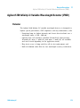
Agilent 1220 Infinity LC Variable Wavelength Detector (VWD)
Agilent 1220 Infinity LC Diode Array Detector (DAD) 114
Match the Flow Cell to the Column 130
9 Test Functions and Calibration
113
135
Agilent 1220 Infinity LC System 137
Solvent Delivery System 139
Autosampler 149
Column Oven 155
Variable Wavelength Detector (VWD) 157
Diode Array Detector (DAD) 167
6
1220 Infinity LC
Contents
10 Error Information
191
What are Error Messages? 194
General Error Messages 195
Pump Error Messages 201
Autosampler Error Messages 213
General Detector Error Messages 222
VWD Detector Error Messages 225
DAD Detector Error Messages 230
11 Maintenance
237
PM Scope of Work and Checklist 239
Cautions and Warnings 240
Solvent Delivery System 242
Manual Injector 263
Autosampler 267
Variable Wavelength Detector (VWD) 285
Diode Array Detector (DAD) 295
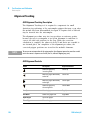
Algae Growth in HPLC Systems 316
Replacing the Module’s Firmware 318
12 Parts for Maintenance
319
1220 Infinity LC System 320
Solvent Delivery System 322
Injection System 331
Column Oven 339
Detector 340
13 Upgrading the Agilent 1220 Infinity LC
Oven Upgrade
1220 Infinity LC
347
348
7
Contents
14 Identifying Cables
349
Cable Overview 350
Analog Cables 352
Remote Cables 354
BCD Cables 357
CAN/LAN Cables 359
Agilent 1200 module to PC
15 Appendix
360
361
General Safety Information 362
Solvent Information 365
Radio Interference 367
UV Radiation 368
Sound Emission 369
Waste Electrical and Electronic Equipment (WEEE) Directive (2002/96/EC)
Declaration of Conformity for HOX2 Filter 371
Agilent Technologies on Internet 372
8
370
1220 Infinity LC
1220 Infinity LC
1
Introduction
Agilent 1220 Infinity LC Configurations
10
Agilent 1220 Infinity LC VL Configurations
11
Early Maintenance Feedback 12
EMF counters for the pump 12
EMF counters for the autosampler 13
EMF counters for the variable wavelength detector
EMF counters for the diode array detector 14
14
This chapter provides an overview of the Agilent 1220 Infinity LC available
configurations.
Agilent Technologies
9
1
Introduction
Agilent 1220 Infinity LC Configurations
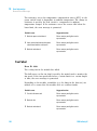
Agilent 1220 Infinity LC Configurations
Available configurations of Agilent 1220 Infinity LC
The Agilent 1220 Infinity LC is available in four different configurations.
Possible components include isocratic pump, dual- channel gradient pump
(with degasser), manual injector, autosampler, column oven and detector.
Each configuration comes with at least one pump, one injection system
and one detector and includes Agilent Instrument Utilities Software.
Isocratic pump
Gradient pump
Gradient pump
Gradient pump
Manual injector
Manual injector
Autosampler
Autosampler
Column oven
Column oven
Variable
wavelength
detector
Diode
array
detector
G4290B
G4294B
Variable
wavelength
detector
G4286B
Variable
wavelength
detector
G4288B
A Solvent Selection Valve (SSV) Upgrade Kit (G4280- 68708) is available.
10
1220 Infinity LC
Introduction
Agilent 1220 Infinity LC VL Configurations
1
Agilent 1220 Infinity LC VL Configurations
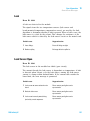
Available configurations of Agilent 1220 Infinity LC VL
The Agilent 1220 Infinity LC VL is available in two different
configurations. Possible components include isocratic pump, dual- channel
gradient pump (with degasser), manual injector, autosampler, column oven
and detector. Each configuration comes with at least one pump, one
injection system and one detector and includes Agilent Instrument Utilities
Software.
<gVY^ZciEjbe
<gVY^ZciEjbe
BVcjVa>c_ZXidg
6jidhVbeaZg
8dajbcDkZc
KVg^VWaZ
KVg^VWaZ
LVkZaZc\i]
LVkZaZc\i]
9ZiZXidg
9ZiZXidg
<)'--8
<)'.%8
A Solvent Selection Valve (SSV) Upgrade Kit (G4280- 68708) is available.
1220 Infinity LC
11
1
Introduction
Early Maintenance Feedback
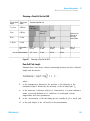
Early Maintenance Feedback
EMF counters for the pump
The user- settable EMF limits for the EMF counters enable the early
maintenance feedback to be adapted to specific user requirements. The
wear of pump components is dependent on the analytical conditions.
Therefore, the definition of the maximum limits needs to be determined
based on the specific operating conditions of the instrument.
The Agilent 1220 Infinity LC pump provides a series of EMF counters for
the pump head. Each counter increments with pump use, and can be
assigned a maximum limit that provides visual feedback in the user
interface when the limit is exceeded. Each counter can be reset to zero
after maintenance has been done. The pump provides the following EMF
counters:
Pump liquimeter
The pump liquimeter displays the total volume of solvent pumped by the
pump head since the last reset of the counters. The pump liquimeter can
be assigned an EMF (maximum) limit. When the limit is exceeded, the
EMF flag in the user interface is displayed.
Seal wear counters
The seal wear counters display a value derived from pressure and flow
(both contribute to seal wear). The values increment with pump usage
until the counters are reset after seal maintenance. Both seal wear
counters can be assigned an EMF (maximum) limit. When the limit is
exceeded, the EMF flag in the user interface is displayed.
12
1220 Infinity LC
1
Introduction
Early Maintenance Feedback
EMF counters for the autosampler
The user- settable EMF limits for the EMF counters enable the early
maintenance feedback to be adapted to specific user requirements. The
wear of autosampler components is dependent on the analytical
conditions. Therefore, the definition of the maximum limits need to be
determined based on the specific operating conditions of the instrument.
The autosampler provides two EMF counters. Each counter increments
with autosampler use, and can be assigned a maximum limit which
provides visual feedback in the user interface when the limit is exceeded.
Each counter can be reset to zero after maintenance has been done. The
autosampler provides the following EMF counters:
Injection valve counter
This counter display the total number of switches of the injection valve
since the last reset of the counter.
Needle movements counter
This counter displays the total number of movements of the needle into
the seat since the last reset of the counter.
1220 Infinity LC
13
1
Introduction
Early Maintenance Feedback
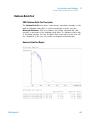
EMF counters for the variable wavelength detector
The user- settable EMF limits for the EMF counter enables the early
maintenance feedback to be adapted to specific user requirements. The
useful lamp burn time is dependent on the requirements for the analysis
(high or low sensitivity analysis, wavelength, and so on). Therefore, the
definition of the maximum limits need to be determined based on the
specific operating conditions of the instrument.
The detector module provides a EMF counter for the lamp. The counter
increments with lamp use, and can be assigned a maximum limit which
provides visual feedback in the user interface when the limit is exceeded.
The counter can be reset to zero after the lamp is exchanged. The detector
provides the following EMF counters:
Deuterium lamp on-time
This counter shows the total burn time of the deuterium lamp in hours.
EMF counters for the diode array detector
Using the EMF Counters
The user- settable EMF limits for the EMF Counters enable the early
maintenance feedback to be adapted to specific user requirements. The
useful maintenance cycle is dependent on the requirements for use.
Therefore, the definition of the maximum limits need to be determined
based on the specific operating conditions of the instrument.
Setting the EMF Limits
The setting of the EMF limits must be optimized over one or two
maintenance cycles. Initially the default EMF limits should be set. When
instrument performance indicates maintenance is necessary, take note of
the values displayed by the EMF counters. Enter these values (or values
slightly less than the displayed values) as EMF limits, and then reset the
EMF counters to zero. The next time the EMF counters exceed the new EMF
limits, the EMF flag will be displayed, providing a reminder that
maintenance needs to be scheduled.
14
1220 Infinity LC
1220 Infinity LC
2
Site Requirements and Specifications
Site Requirements 16
Power Considerations
Power Cord 17
Bench Space 17
Environment 18
Physical Specifications
16
19
Performance Specifications 20
Specification Conditions 27
This chapter provides information on environmental requirements, physical and
performance specifications.
Agilent Technologies
15
2
Site Requirements and Specifications
Site Requirements
Site Requirements
A suitable environment is important to ensure optimal performance of the
instrument.
Power Considerations
The Agilent 1220 Infinity LC power supply has wide- ranging capabilities.
Consequently, there is no voltage selector at the instrument.
WA R N I N G
Instrument is partially energized when switched off
The power supply still uses some power even when the power switch on the front
panel is turned OFF. Repair work at the detector can lead to personal injuries, e. g.
shock hazard, when the detector cover is opened and the instrument is connected to
power.
➔ To disconnect the detector from the power line, unplug the power cord.
WA R N I N G
Incorrect line voltage to the instrument
Shock hazard or damage to your instrumentation can result if the devices are
connected to a line voltage higher than specified.
➔ Connect your instrument only to the specified line voltage.
CAUTION
In case of an emergency, it must be possible to disconnect the instrument from the
power line at any time.
Make sure that there is easy access to the power cable of the instrument so that the
instrument can quickly and easily be disconnected from the line voltage.
➔ Provide sufficient space next to the power socket of the instrument to allow the
cable to be unplugged.
16
1220 Infinity LC
2
Site Requirements and Specifications
Site Requirements
Power Cord
Different power cords are offered as options with the system. The female
ends of all power cords are identical. The female end plugs into the
power- input socket at the rear left side of the instrument. The male end
of each power cord is different and designed to match the wall socket of
a particular country or region.
WA R N I N G
Absence of ground connection or use of unspecified power cord
The absence of ground connection or the use of unspecified power cord can lead to
electric shock or short circuit.
➔ Never operate your instrument from a power outlet that has no ground connection.
➔ Never use a power cord other than the Agilent Technologies power cord designed
for your region.
WA R N I N G
Use of cables not supplied by Agilent
Using cables that have not been supplied by Agilent Technologies can lead to
damage of the electronic components or personal injury.
➔ Never use cables other than the ones supplied by Agilent Technologies to ensure
proper functionality and compliance with safety or EMC regulations.
Bench Space
The dimensions and weight of the Agilent 1220 Infinity LC allow it to be
placed on almost any desk or laboratory bench. It needs an additional
2.5 cm (1.0 in) of space on either side and approximately 8 cm (3.1 in) at
the rear for air circulation and electric connections.
Make sure that the bench intended to carry the Agilent 1220 Infinity LC
is designed to bear the weight of the instrument.
The Agilent 1220 Infinity LC should be operated upright.
1220 Infinity LC
17
2
Site Requirements and Specifications
Site Requirements
Environment
Your Agilent 1220 Infinity LC will work within specifications at ambient
temperatures and relative humidity as described in the following sections.
ASTM drift tests require a temperature change below 2 °C/hour
(3.6 °F/hour) measured over one hour period. Our published drift
specification is based on these conditions. Larger ambient temperature
changes will result in larger drift.
Better drift performance depends on better control of the temperature
fluctuations. To realize the highest performance, minimize the frequency
and the amplitude of the temperature changes to below 1 °C/hour
(1.8 °F/hour). Turbulences around one minute or less can be ignored.
CAUTION
Condensation within the module
Condensation can damage the system electronics.
➔ Do not store, ship or use your module under conditions where temperature
fluctuations could cause condensation within the module.
➔ If your module was shipped in cold weather, leave it in its box and allow it to warm
slowly to room temperature to avoid condensation.
18
1220 Infinity LC
2
Site Requirements and Specifications
Physical Specifications
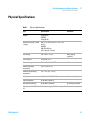
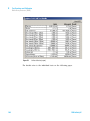
Physical Specifications
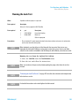
Table 1
1220 Infinity LC
Physical Specifications
Type
Specification
Comments
Weight
30 kg (66 lbs)
G4294B:
43 kg (94 lbs)
Dimensions (height × width
× depth)
640 × 370 × 420 mm (25.2 × 14.6 × 16.5
inches)
G4294B:
640×370×485 mm
(25.2×14.6×19.1 inches)
Line voltage
100 – 240 V~, ± 10 %
Line frequency
50 or 60 Hz, ± 5 %
Power consumption
240 VA / 210 W / 717 BTU
Ambient operating
temperature
4–55 °C (39–131 °F)
Ambient non-operating
temperature
-40 – 70 °C (-40 – 158 °F)
Humidity
< 95 % r.h. at 40 °C (104 °F)
Operating altitude
Up to 2000 m (6562 ft)
Non-operating altitude
Up to 4600 m (15092 ft)
For storing the module
Safety standards: IEC, CSA,
UL
Installation category II, Pollution degree 2
For indoor use only.
Wide-ranging
capability
Maximum
Non-condensing
19
2
Site Requirements and Specifications
Performance Specifications
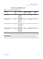
Performance Specifications
Performance Specifications Agilent 1220 Infinity LC
Table 2
20
Performance Specifications Agilent 1220 Infinity LC
Type
Specification
Safety features
Extensive diagnostics, error detection and
display, leak detection, safe leak handling, leak
output signal for shutdown of pumping system.
Low voltages in major maintenance areas.
Control and data evaluation
Agilent EZChrom Compact, Agilent
ChemStation, Agilent Instrument Utilities,
Agilent Lab Advisor
Communications
Controller-area network (CAN), RS-232C, APG
Remote: ready, start, stop and shut-down
signals, LAN
GLP features
Early maintenance feedback (EMF), electronic
records of maintenance and errors
1220 Infinity LC
Site Requirements and Specifications
Performance Specifications
2
Performance Specifications Agilent 1220 Infinity LC Pump
Table 3
1220 Infinity LC
Performance Specifications Agilent 1220 Infinity LC Pump
Type
Specification
Hydraulic system
Dual plunger in series pump with proprietary servo-controlled
variable stroke drive, floating plungers and passive inlet valve
Settable flow range
0.001 – 10 mL/min, in 0.001 mL/min increments
Flow range
0.2 – 10.0 mL/min
Flow precision
≤0.07 % RSD, or < 0.02 min SD whatever is greater, based on
retention time at constant room temperature
Flow accuracy
± 1 % or 10 µL/min whatever is greater; degassed H2O, 80 –
100 bar, 1 mL/min, at constant ambient temperature
Pressure
Operating range 0 – 60 MPa (0 – 600 bar, 0 – 8820 psi) up to
5 mL/min
Operating range 0 – 20 MPa (0 – 200 bar, 0 – 2950 psi) up to
10 mL/min
Pressure pulsation
< 2 % amplitude (typically < 1.3 %), at 1 mL/min isopropanol, at all
pressures > 1 MPa (10 bar)
Compressibility
compensation
User-selectable, based on mobile phase compressibility
Recommended pH range
1.0 – 12.5, solvents with pH < 2.3 should not contain acids which
attack stainless steel
Gradient formation
(optional)
Low pressure binary mixing/gradient capability using proprietary
high-speed proportioning valve
Delay volume
600 – 900 µL, dependent on back pressure; measured with water at
1 mL/min (water/caffeine tracer)
Composition range
0 – 95 % or 5 – 100, user selectable
Composition precision
< 0.2 % RSD or < 0.4 min SD, whatever is greater, at 1 mL/min;
based on retention time at constant room temperature
21
2
Site Requirements and Specifications
Performance Specifications
Performance Specifications Agilent 1220 Infinity LC Pump VL
Table 4
22
Performance Specifications Agilent 1220 Infinity LC Pump VL
Type
Specification
Hydraulic system
Dual plunger in series pump with proprietary servo-controlled
variable stroke drive, floating plungers and passive inlet valve
Settable flow range
0.001 – 10 mL/min, in 0.001 mL/min increments
Flow range
0.2 – 10 mL/min
Flow precision
<0.07 % RSD, or < 0.02 min SD whatever is greater, based on
retention time at constant room temperature
Flow accuracy
± 1 % or 10 µL/min whatever is greater
Pressure
Operating range 0 – 40 MPa (0 – 400 bar, 0 – 5880 psi) up to
5 mL/min
Operating range 0 – 20 MPa (0 – 200 bar, 0 – 2950 psi) up to
10 mL/min
Pressure pulsation
< 2 % amplitude (typically < 1 %), at 1 mL/min isopropanol, at all
pressures > 1 MPa (10 bar)
Compressibility
compensation
User-selectable, based on mobile phase compressibility
Recommended pH range
1.0 – 12.5, solvents with pH < 2.3 should not contain acids which
attack stainless steel
Gradient formation
(optional)
Low pressure dual mixing/gradient capability using proprietary
high-speed proportioning valve Delay volume 800 – 1100 µL,
dependent on back pressure
Composition Range
0 – 95 % or 5 – 100 %, user selectable
Composition Precision
< 0.2 % RSD, at 0.2 and 1 mL/min
1220 Infinity LC
2
Site Requirements and Specifications
Performance Specifications
Performance Specifications Agilent 1220 Infinity LC Autosampler
Table 5
Performance Specifications Agilent 1220 Infinity LC Autosampler
Type
Specification
Pressure
Operating range 0 – 60 MPa (0 – 600 bar, 0 – 8820 psi)
Injection range
0.1 – 100 µL in 0.1 µL increments Up to 1500 µL with multiple draw
(hardware modification required)
Replicate injections
1 – 99 from one vial
Precision
< 0.25 % RSD from 5 – 100 µL, < 1 % RSD 1 – 5 µL
variable volume
Minimum sample volume
1 µL from 5 µL sample in 100 µL microvial, or 1 µL from 10 µL sample
in 300 µL microvial
Carryover
Typically < 0.1 %, < 0.05 % with external needle cleaning
Sample viscosity range
0.2 – 50 cp
Sample capacity
100 × 2 mL vials in 1 tray
40 × 2 mL vials in ½ tray
15 × 6 mL vials in ½ tray (Agilent vials only)
Injection cycle time
Typically 50 s depending on draw speed and injection volume
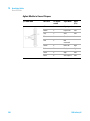
Performance Specifications Agilent 1220 Infinity LC Column Oven
Table 6
1220 Infinity LC
Performance Specifications Agilent 1220 Infinity LC Column Oven
Type
Specification
Temperature range
5 °C above ambient to 60 °C
5 °C above ambient to 80 °C (min. FW Rev.
B.06.50)
Temperature stability
± 0.15 °C, constant Composition and Flow Rate
Temperature accuracy
± 0.8 °C
Column capacity
one 25 cm column
Internal volume
6 µL
23
2
Site Requirements and Specifications
Performance Specifications
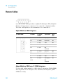
Performance Specifications Agilent 1220 Infinity LC VWD
Table 7
24
Performance Specifications Agilent 1220 Infinity LC VWD
Type
Specification
Comments
Detection type
Double-beam photometer
Light source
Deuterium lamp
Wavelength range
190 – 600 nm
Short term noise (ASTM)
<± 0.25·10-5 AU at 230 nm
See “Specification
Conditions” on page 27
Drift
< 1·10-4 AU/h at 230 nm
See “Specification
Conditions” on page 27
Linearity
> 2 AU (5 %) upper limit
See “Specification
Conditions” on page 27
Wavelength accuracy
± 1 nm
Self-calibration with
deuterium lines, verification
with holmium oxide filter
Maximum data rate
80 Hz
Band width
6.5 nm typical
Flow cells
Standard: 14 µL volume,
10 mm cell path length and
40 bar (580 psi) pressure
maximum
High pressure: 14 µL volume,
10 mm cell path length and
400 bar (5800 psi) pressure
maximum
Micro: 1 µL volume, 5 mm cell
path length and 40 bar
(580 psi) pressure maximum
Semi-micro: 5 µL volume,
6 mm cell path length and
40 bar (580 psi) pressure
maximum
Analog outputs
Recorder/integrator: 100 mV
or 1 V, output range 0.001 to
2 AU, one output
Can be repaired on component
level
1220 Infinity LC
2
Site Requirements and Specifications
Performance Specifications
Table 7
NOTE
1220 Infinity LC
Performance Specifications Agilent 1220 Infinity LC VWD
Type
Specification
Communications
Controller-area network
(CAN), RS-232C, APG Remote:
ready, start, stop and
shut-down signals, LAN
(optional)
Safety and maintenance
Extensive diagnostics, error
detection and display (through
Agilent ChemStation), leak
detection, safe leak handling,
leak output signal for
shutdown of pumping system.
Low voltages in major
maintenance areas.
GLP features
Early maintenance feedback
(EMF) for continuous tracking
of instrument usage in terms
of lamp burn time with
user-settable limits and
feedback messages.
Electronic records of
maintenance and errors.
Verification of wavelength
accuracy with built-in holmium
oxide filter.
Housing
All materials recyclable.
Comments
ASTM: “Standard Practice for Variable Wavelength Photometric Detectors Used in Liquid
Chromatography”.Reference conditions: cell path length 10 mm, response time 2 s, flow
1 mL/min LC-grade methanol. Linearity measured with caffeine at 272 nm.
25
2
Site Requirements and Specifications
Performance Specifications
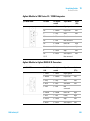
Performance Specifications Agilent 1220 Infinity LC DAD
Table 8
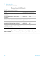
26
Performance Specifications
Type
Specification
Comments
Detection type
1024-element diode array
Light source
Deuterium and tungsten lamps
Number of signals
8
Maximum sampling
rate
80 Hz
Short term noise
(ASTM) Single and
Multi-Wavelength
< ± 0.7·10-5 AU at 254/4 nm and
750 nm, TC 2 s
see "Specification Conditions"
below
Drift
< 0.9·10-3 AU/h at 254 nm
see "Specification Conditions"
below
Linear absorbance
range
> 2 AU (5 %) at 265 nm
see "Specification Conditions"
below
Wavelength range
190 – 950 nm
Wavelength
accuracy
± 1 nm
Self-calibration with deuterium
lines, verification with holmium
oxide filter
Slit width
1, 2, 4 , 8, 16 nm
Programmable slit
Diode width
< 1 nm
Flow cell
Standard: 13 µL volume, 10 mm cell
path length and 120 bar (1740 psi)
pressure maximum
Time programmable
Wavelength, polarity, peak width,
lamp bandwidth, autobalance,
wavelength range, threshold, spectra
storage mode
The UV-lamp is equipped with
RFID tag that holds lamp typical
information.
The flow cell is equipped with
RFID tags that hold cell typical
information.
pH range 1.0—9.5
1220 Infinity LC
2
Site Requirements and Specifications
Performance Specifications
Specification Conditions
ASTM: “Standard Practice for Variable Wavelength Photometric Detectors
Used in Liquid Chromatography”.
Reference conditions: Standard flow cell, path length 10 nm, flow
1 mL/min LC- grade methanol.
Noise:
<± 0.5·10- 5 AU at 254 nm, TC 2 s, ASTM
RT = 2.2 * TC
Linearity:
Linearity is measured with caffeine at 265 nm.
NOTE
The specifications are based on the standard lamp (G1314-60100) and may be not achieved
when other lamp types or aged lamps are used.
ASTM drift tests require a temperature change below 2 °C/hour
(3.6 F/hour) over one hour period. Our published drift specification is
based on these conditions. Larger ambient temperature changes will result
in larger drift.
Better drift performance depends on better control of the temperature
fluctuations. To realize the highest performance, minimize the frequency
and the amplitude of the temperature changes to below 1 °C/hour
(1.8 F/hour). Turbulences around one minute or less can be ignored.
Performance tests should be done with a completely warmed up optical
unit (> two hours). ASTM measurements require that the detector should
be turned on at least 24 hours before start of testing.
Time Constant versus Response Time
According to ASTM E1657- 98 „Standard Practice of Testing
Variable- Wavelength Photometric Detectors Used in Liquid
Chromatography” the time constant is converted to response time by
multiplying by the factor 2.2.
1220 Infinity LC
27
2
28
Site Requirements and Specifications
Performance Specifications
1220 Infinity LC
1220 Infinity LC
3
Installation
Unpacking Your System 30
Delivery Checklist 30
Installing the Hardware 34
Installation Paths 34
Installing the Agilent 1220 Infinity LC 36
Identifying the connections of the 1220 Infinity LC
41
Connecting and Configuring the Instrument to the Chromatographic Data
System 43
Connecting the Agilent 1220 Infinity LC to the PC
The Instrument Utility / LabAdvisor Software
44
46
Configuration of the Instrument After an Upgrade Installation
Priming the System and Performing the ‘Installation Check’
Performing a ‘Checkout Run’
47
48
49
This chapter provides an overview on shipment content and installation.
NOTE
To install the Agilent 1220 Infinity LC System, it is highly recommended to follow the
installation instructions step by step.
Agilent Technologies
29
3
Installation
Unpacking Your System
Unpacking Your System
If the delivery packaging shows signs of external damage, please call your
Agilent Technologies sales and service office immediately. Inform your
service representative that the Agilent 1220 Infinity LC may have been
damaged during shipment.
CAUTION
Signs of damage
➔ Do not attempt to install the Agilent 1220 Infinity LC.
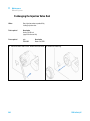
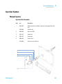
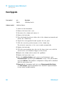
Delivery Checklist
Delivery Checklist
Ensure all parts and materials have been delivered with the Agilent 1220
Infinity LC. The delivery checklist is shown below. Please report missing
or damaged parts to your local Agilent Technologies sales and service
office.
Table 9
30
Agilent 1220 Infinity Checklist
Description
Quantity
Agilent 1220 Infinity LC
1
Power cable
1
Flow cell
Installed
User Manual on Documentation CD (part of the
shipment - not module specific)
1 per order
Installation guide
1
Accessory kit (see below)
1
1220 Infinity LC
Installation
Unpacking Your System
3
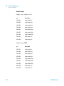
Accessory Kit Contents for G4286B
1220 Infinity LC
p/n
Description
G4286-68755
Accessory kit complete
0100-2562
Fitting, onepiece, fingertight
0890-1195
PTFE tubing, 0.052 in i.d.
0890-1711
Flexible tubing (to waste), 3 m
5023-0203
Cross-over network cable, shielded, 3 m (for point to point
connection)
5062-8535
Waste accessory kit
5188-2758
PTFE/silicone septa 16mm pre-silt 100/pk
(delivered quantity is 0.010)
5190-1501
Syringe, 50.0 µL, FN, LC tip
9301-0411
Syringe, Plastic
9301-1337
Syringe adapter
9301-1377
Screw Cap Vial, clear, 6 mL 100/PK
(delivered quantity is 0.010)
9301-1379
Screw caps for 6 mL vials 100/PK
(delivered quantity is 0.010)
9301-1420
Solvent bottle, transparent
G1311-60003
Bottle-head assembly
31
3
Installation
Unpacking Your System
Accessory Kit Contents for G4288B/C
32
p/n
Description
G4288-68755
Accessory kit complete
0100-2562
Fitting, onepiece, fingertight
0890-1195
PTFE tubing, 0.052 in i.d.
0890-1711
Flexible tubing (to waste), 3 m
5023-0203
Cross-over network cable, shielded, 3 m (for point to point
connection)
5062-8535
Waste accessory kit
5188-2758
PTFE/silicone septa 16mm pre-silt 100/pk
(delivered quantity is 0.010)
5190-1501
Syringe, 50.0 µL, FN, LC tip
9301-0411
Syringe, Plastic
9301-1337
Syringe adapter
9301-1377
Screw Cap Vial, clear, 6 mL 100/PK
(delivered quantity is 0.010)
9301-1379
Screw caps for 6 mL vials 100/PK
(delivered quantity is 0.010)
9301-1420
Solvent bottle, transparent
9301-1450
Solvent bottle, amber
G1311-60003 (2x)
Bottle-head assembly
1220 Infinity LC
Installation
Unpacking Your System
3
Accessory Kit Contents for G4290B/C, G4294B
p/n
Description
G4290-68755
Accessory kit complete
0100-2562
Fitting, onepiece, fingertight
0890-1195
PTFE tubing, 0.052 in i.d.
0890-1711
Flexible tubing (to waste), 3 m
5023-0203
Cross-over network cable, shielded, 3 m (for point to point connection)
5062-8535
Waste accessory kit
9301-0411
Syringe, Plastic
9301-1337
Syringe adapter
9301-1420
Solvent bottle, transparent
9301-1450
Solvent bottle, amber
G1311-60003
Bottle-head assembly
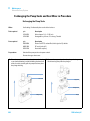
Optional Tool Kit for Agilent 1220 Infinity LC
1220 Infinity LC
p/n
Description
G4296-68715
Tool kit complete
0100-1710
Mounting Tool for Tubing Connections
8710-0510
Wrench open 1/4 — 5/16 inch
8710-1924
Wrench open 14 mm
8720-0025
Wrench, 1/2 inch & 9/16 inch
01018-23702
Insert tool
8710-2392
Hex key 4 mm15 cm long T-handle
8710-2394
Hex key 9/64 inch 15 cm long T-handle
8710-2411
Hex key 3 mm12 cm long
8710-2412
Hex key 2.5 mm, 15 cm long, straight handle
8710-0899
Pozidriv screwdriver
33
3
Installation
Installing the Hardware
Installing the Hardware
Installation Paths
Standard Installation Path
Installation Path Including the Installation of Upgrade Kits
(No optional hardware upgrade is added to the module
during installation)
(Oven upgrade kit /Manual injector to ALS upgrade kit/
Isocratic to gradient upgrade kit)
NOTE
The Installation of the gradient system upgrade kit
and ALS upgrade kit must be done from Agilenttrained service personnel only.
34
1220 Infinity LC
3
Installation
Installing the Hardware
Standard Installation Path
=VgYlVgZ>chiVaaVi^dc
Installation Path Including the Installation of Upgrade Kits
=VgYlVgZ>chiVaaVi^dc
>cXajY^c\^chiVaaVi^dcd[
]VgYlVgZje\gVYZh`^ih
8dc[^\jgZcZildg`VXXZhhd[
6\^aZci&''%>c[^c^inA8
8dc[^\jgZcZildg`VXXZhh
d[6\^aZci&''%>c[^c^inA8
>chigjbZciXdc[^\jgVi^dc^c89H
;ajh]i]ZhnhiZbVcYeZg[dgbi]Z
^chiVaaVi^dcX]ZX`VcYeZg[dgbV
hVbeaZX]ZX`djigjc
8dc[^\jgZ$hZicZl^chigjbZci
ineZ^ci]Z>chigjbZciJi^a^in$
AVW6Yk^hdghd[ilVgZ
8dc[^\jgZ^chigjbZci^c
89HVcYhiVgi89H
;ajh]i]ZhnhiZbVcYeZg[dgbi]Z
^chiVaaVi^dcX]ZX`VcYeZg[dgbV
hVbeaZX]ZX`djigjc
NOTE
The installation of a Solvent Selection Valve (SSV)
Option does not require the configuration of a new
instrument type. The SSV needs to be configured in
the CDS only.
1220 Infinity LC
35
3
Installation
Installing the Hardware
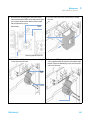
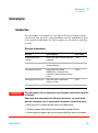
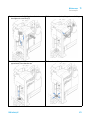
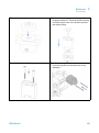
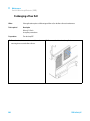
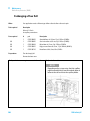
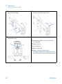
Installing the Agilent 1220 Infinity LC
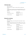
1 Open the box and compare its content with the delivery checklist for
completeness.
2 Place the Agilent 1220 Infinity LC on top of the bench.
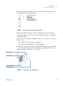
3 Remove both front covers (top and lower) by pressing the release
buttons (on both sides).
Figure 1
36
Front Cover Mechanism
1220 Infinity LC
Installation
Installing the Hardware
3
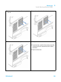
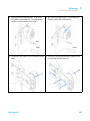
4 Remove the two transport foams.
Figure 2
Remove the Transport Foam
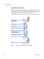
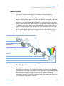
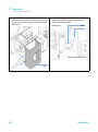
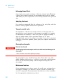
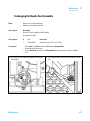
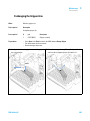
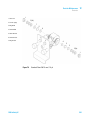
Figure 3 on page 38 shows the content of a fully equipped 1220 Infinity
LC system with removed front covers. (Module type shown G4290B)
1220 Infinity LC
37
3
Installation
Installing the Hardware
HdakZciigVn
<gVY^Zciejbel^i]
YZ\VhhZgdg^hdXgVi^X
ejbe!cdih]dlc
HdakZcihZaZXi^dckVakZ
dei^dcVa!cdih]dlc
6jidhVbeaZgdgbVcjVa
^c_ZXidg!cdih]dlc
8dajbcdkZcdei^dcVa
>ciZg[VXZXdccZXidgh
A6C!86C!edlZg
KVg^VWaZLVkZaZc\i]
9ZiZXidgKL9
EdlZgejh]Wjiidc
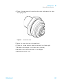
Figure 3
NOTE
System Overview 1220 Infinity LC
Additional options or upgrade kits should be installed prior to all solvent path installations.
Configuring your Agilent 1220 Infinity LC Module Information can be found in the
“Configuration of the Instrument After an Upgrade Installation” on page 47.
For further information about how to install the options and upgrade kits refer to Agilent
1220 Infinity LC Module manual.
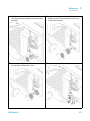
5 Place the Solvent Bottle filled with 0.5 L HPLC grade water in the
Solvent Tray.
38
1220 Infinity LC
Installation
Installing the Hardware
3
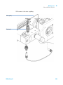
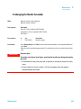
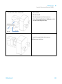
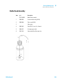
6 Place the Solvent Inlet Filter end of the Bottle Head Assembly in the
Solvent Bottle (see picture below).
)
(
'
&
&;ZggjaZhl^i]adX`g^c\
'IjWZhXgZl
(L^gZbVg`Zg
)HdakZciijW^c\!*b
*;g^iVYVeiZgeVX`d[)
+HdkZci^caZi[^aiZg!'%¥b
*
+
Figure 4
Bottle Head Assembly and Solvent Bottle
7 Prime the tubing using the Syringe (9301- 044) and Syringe adapter
(9301- 1337) (part of the Accessory kit) until the tubing is completely
filled with water.
8 Connect the Bottle Head Assembly connector (see Figure 4 on page 39
Item 1+2) to:
• the passive inlet valve (isocratic pump) or
• the degasser inlet Channel A (gradient pump).
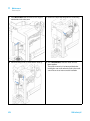
9 Connect the waste tube with the fitting attached (part of Accessory Kit)
to the flow cell outlet and the other end to an appropriate solvent
waste container (see Figure 5 on page 39).
;adlXZaa^caZi
;adlXZaadjiaZi
EdlZgejh]Wjiidc
AZV`igVndjiaZi
Figure 5
1220 Infinity LC
Connections at the VWD Module
39
3
Installation
Installing the Hardware
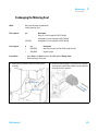
10 Attach the corrugated waste tube (part of Accessory Kit) to the VWD
leak tray outlet adapter and guide it to a proper waste container (see
Figure 5 on page 39).
11 Connect the waste tube (part of Accessory Kit) to the purge valve outlet
adapter and the other end to the waste container.
12 Connect the network connection between the Agilent 1220 Infinity LC
and your PC.
NOTE
More details about how to establish a network connection to the instrument can be found
in “Connecting the Agilent 1220 Infinity LC to the PC” on page 44 or “LAN
Configuration” on page 51
13 Verify that the power push button at the front of the module (see
Figure 5 on page 39) stands off. Now connect the power cord to the
Agilent 1220 Infinity LC and the power line.
14 Before switching on the module check that all transport foams have
been de- installed (see Figure 2 on page 37). Then switch on the module
via the power push button.
40
1220 Infinity LC
Installation
Installing the Hardware
3
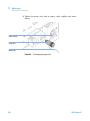
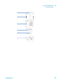
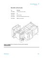
Identifying the connections of the 1220 Infinity LC
Agilent 1220 Infinity LC with VWD
Figure 6 on page 41 shows an overview of the possible connections on the
1220 Infinity LC instrument with VWD.
MAC address label
LAN connector
RS232 serial and remote
connectors
CAN port
Configuration dip switches
(for boot mode selection)
Fuses
Power plug
Figure 6
1220 Infinity LC
Connections of the Agilent 1220 Infinity LC with VWD
41
3
Installation
Installing the Hardware
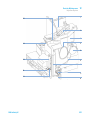
Agilent 1220 Infinity LC with DAD
Figure 7 on page 42 shows an overview of the possible connections on the
1220 Infinity LC instrument with DAD. On the G4294B you must use the
configuration dip switches on the DAD mainboard because this will be the
communication host in this case. The short CAN cable is the
communication connection between the DAD and the other 1220 modules.
CAN connection
between DAD and
instrument mainboard
MAC address label
LAN connector
RS232 serial and remote connectors
CAN port
Configuration dip switches
(for boot mode selection)
A/D signal output (DAD board only)
Fuses
Power plug
Figure 7
42
Connections of the Agilent 1220 Infinity LC with DAD
1220 Infinity LC
Installation
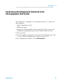
Connecting and Configuring the Instrument to the Chromatographic Data System
3
Connecting and Configuring the Instrument to the
Chromatographic Data System
The instrument is compatible to the following software for control and
data evaluation:
• Agilent ChemStation for LC
• EZChrom Software
1 Install your Chromatographic Data System (CDS). Please refer to the
installation documentation that has been delivered with the CDS.
2 Start your CDS.
3 At the instrument configuration screen enter the Instrument name (free
of choice) and the Instrument type (Agilent Compact LC).
4 For configuring the module choose Auto Configuration.
1220 Infinity LC
43
3
Installation
Connecting the Agilent 1220 Infinity LC to the PC
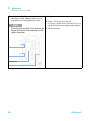
Connecting the Agilent 1220 Infinity LC to the PC
The AGILENT 1220 Infinity LC is delivered from factory with the default
network configuration settings. (Configuration dip switches 7 & 8 set to
ON). This enables you to quickly connect it via the crossover patch cable
(part of the accessory kit) with your PC.
Factory default IP address:
192.168.254.11
LAN port
Configuration dip switches
Instrument with DAD
Figure 8
NOTE
44
Instrument with VWD
Location of the Configuration Dip Switches and LAN Port
On the G4294B use the configuration dip switches of the DAD extension board to configure
your LAN connection.
1220 Infinity LC
Installation
Connecting the Agilent 1220 Infinity LC to the PC
3
1 To connect the instrument with your PC using this default address
configure the PC’s network settings as followed:
IP:
192.168.254.10
Subnet Mask:
255.255.255.0
Default Gateway:
N/A
2 Connect the crossover patch cable between the LAN- Port of the Agilent
1220 Infinity LC (Figure 8 on page 44) and the network connector of
your PC.
NOTE
The crossover cable is only for the direct connection between the module and the PC. If you
want to connect your Agilent 1220 Infinity LC via a hub to the network you should contact
your local network administrator.
If you want to connect the instrument to a network we strongly
recommend consulting your local network administrator to provide you
with a valid network address. For further details about LAN configuration
of the Agilent 1220 Infinity LC please refer to the LAN Configuration
section of the Installation chapter in the1220 Infinity LC User Manual.
Here you find details about:
• TCP/IP parameter configuration
• Configuration Switches
• Using a fixed IP address
• How to configure an individual IP address
1220 Infinity LC
45
3
Installation
The Instrument Utility / LabAdvisor Software
The Instrument Utility / LabAdvisor Software
During the installation process of the Agilent 1220 Infinity LC this
software is used for flushing the system and performing the System
Installation check (see “Priming the System and Performing the
‘Installation Check’” on page 48).
1 Install the Instrument Utility or Lab Advisor software according to the
Installation Procedure on the software CD.
2 Setup your Instrument to the software and Connect it.
NOTE
46
Whenever a hardware upgrade (Isocratic to Gradient, Column Oven, Autosampler upgrade)
has been installed, it is necessary to re-configure your instrument in the Instrument Utility
/ Lab Advisor software. Therefore please follow the steps that are described in
“Configuration of the Instrument After an Upgrade Installation” on page 47 before you
proceed.
1220 Infinity LC
3
Installation
Configuration of the Instrument After an Upgrade Installation
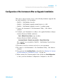
Configuration of the Instrument After an Upgrade Installation
This step is only necessary if any of the following hardware upgrade kits
has been installed to the instrument.
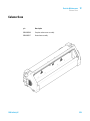
• G4297A - 1220 Infinity Oven kit
• G4298A - 1220 Infinity upgrade manual injector to ALS
• G4299A - 1220 Infinity upgrade isocratic to gradient pump
1 Connect the Instrument to the Instrument Utility / Lab Advisor
software.
2 Configure your Instrument according to the applied hardware changes:
Software Revision B.01.04 and below:
• Tools > Module Service Center (any module)
Software Revision B.02.01 and higher:
• Instrument Control > Controls (any module) > Convert Device Type
(For example if you installed a G4297A - 1220 Infinity Oven kit then
press Add Oven
3 Disconnect from the software and re- boot your instrument.
4 Re- connect to the Instrument to the Instrument Utility / Lab Advisor
software.
5 Now perform the Installation Check as described in “Priming the System
and Performing the ‘Installation Check’” on page 48.
6 When starting the Chromatographic Data System use Auto Configuration
to have your new hardware configuration configured to the CDS.
1220 Infinity LC
47
3
Installation
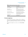
Priming the System and Performing the ‘Installation Check’
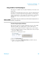
Priming the System and Performing the ‘Installation Check’
The steps described below are performed using the Instrument Utility /
Lab Advisor software.
1 Connect all channels with HPLC grade water and use the Purge Pump for
flushing the solvent channels.
Software Revision B.01.04 and below:
• Tools > Pump > Purge Pump
Software Revision B.02.01 and higher:
• Service & Diagnostics > Pump (Tools must be checked) > Purge Pump
2 Prime all connected channels sufficiently until all channels are bubble
free.
3 Use the Instrument Control functionality to prime your system with HPLC
grade water to remove air out of the system.
Apply the following conditions:
• Purge Valve: closed
• Flow: 2 mL/min
• Time: 5 min/channel
• Set stroke: 100 µL
4 Perform the Installation Check from the Service and Diagnostics menu and
print out the test result.
5 Create and print out a Status Report.
48
1220 Infinity LC
3
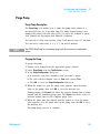
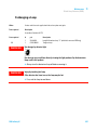
Installation
Performing a ‘Checkout Run’
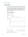
Performing a ‘Checkout Run’
1 Start the Chromatographic Data System
2 Create a checkout method with the following parameters:
• Flow: 1 mL/min
• Inj. Volume: 20 µL (Autosampler)
• Oven temp: not controlled
• VWD Wavelength: 254 nm
• Runtime: 1 min
This checkout run is done with the factory installed ‘restriction
capillary’ in place.
3 Prepare 1ml of a checkout sample (acetone for example) and put it on
vial position 1 in the autosampler tray.
For Manual Injector configurations load 20 µL of checkout sample in
the loop. Overfill the injection loop at least 3 times. (e.g. inject at least
60 µL at a 20 µL sample loop)
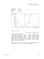
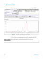
4 Start a single run.
As result a single peak should be visible.
5 Print out the report.
6 Store all created and printed out reports in a binder.
Now you are finished with the installation of the Agilent 1220 Infinity
LC.
1220 Infinity LC
49
3
50
Installation
Performing a ‘Checkout Run’
1220 Infinity LC
1220 Infinity LC
4
LAN Configuration
To do first
52
TCP/IP parameter configuration
Configuration Switches
54
55
Initialization mode selection
56
Dynamic Host Configuration Protocol (DHCP)
General Information (DHCP) 60
Setup (DHCP) 61
Link configuration selection
60
63
Automatic Configuration with BootP 64
About Agilent BootP Service 64
How BootP Service Works 65
Situation: Cannot Establish LAN Communication 65
Installation of BootP Service 66
Two Methods to Determine the MAC Address 68
Assigning IP Addresses Using the Agilent BootP Service 69
Changing the IP Address of an Instrument Using the Agilent BootP
Service 72
Storing the settings permanently with Bootp
Manual Configuration
With Telnet 76
74
75
This chapter provides information on connecting the instrument to the Agilent
ChemStation PC.
Agilent Technologies
51
4
LAN Configuration
To do first
To do first
The Agilent 1220 Infinity LC has an on- board LAN communication
interface.
1 Note the MAC (Media Access Control) address for further reference. The
MAC or hardware address of the LAN interfaces is a world wide unique
identifier. No other network device will have the same hardware
address. The MAC address can be found on a label at the rear left side
of the instrument next to the configuration switch.
EVgicjbWZgd[i]ZYZiZXidg
bV^cWdVgYGZk^h^dc8dYZ!
KZcYdg!NZVgVcYLZZ`
d[VhhZbWanB68VYYgZhh
8djcignd[Dg^\^c
Figure 9
52
MAC label
1220 Infinity LC
LAN Configuration
To do first
4
2 Connect the instrument's LAN interface to
• the PC network card using a crossover network cable (point- to- point)
or
• a hub or switch using a standard LAN cable.
MAC label
LAN port
Instrument with DAD
Figure 10
1220 Infinity LC
Instrument with VWD
Location of LAN interface and MAC label
53
4
LAN Configuration
TCP/IP parameter configuration
TCP/IP parameter configuration
To operate properly in a network environment, the LAN interface must be
configured with valid TCP/IP network parameters. These parameters are:
• IP address
• Subnet Mask
• Default Gateway
The TCP/IP parameters can be configured by the following methods:
• by automatically requesting the parameters from a network- based
BOOTP Server (using the so- called Bootstrap Protocol)
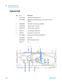
• by automatically requesting the parameters from a network- based DHCP
Server (using the so- called Dynamic Host Configuration Protocol). This
mode requires a LAN- onboard Module or a G1369C LAN Interface card,
see “Setup (DHCP)” on page 61
• by manually setting the parameters using Telnet
The LAN interface differentiates between several initialization modes. The
initialization mode (short form ‘init mode’) defines how to determine the
active TCP/IP parameters after power- on. The parameters may be derived
from a Bootp cycle, non- volatile memory or initialized with known default
values. The initialization mode is selected by the configuration switch, see
Table 11 on page 56.
54
1220 Infinity LC
4
LAN Configuration
Configuration Switches
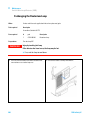
Configuration Switches
The configuration switch can be accessed at the rear left side of the
instrument.
The Agilent 1220 Infinity LC is shipped with switches 7 and 8 set to ON,
which means that the instrument is set to a default fixed IP address:
192.168.254.11
NOTE
To configure the LAN, SW1 and SW2 must be set to OFF.
Table 10
NOTE
1220 Infinity LC
Factory Default Settings
Initialization (‘Init’) Mode
Using Default, switches 7 and 8 set to ON.
Link Configuration
Speed and duplex mode determined by auto-negotiation
For the G4294B, the Configuration switches on the DAD main board must be used for
configuring the LAN access of the instrument. The switches on the 1220 Infinity LC main
board must all be set to off.
55
4
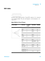
LAN Configuration
Initialization mode selection
Initialization mode selection
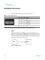
The following initialization (init) modes are selectable:
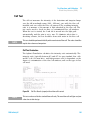
Table 11
1
Initialization Mode Switches
SW 6
SW 7
SW 8
Init Mode
OFF
OFF
OFF
Bootp
OFF
OFF
ON
Bootp & Store
OFF
ON
OFF
Using Stored
OFF
ON
ON
Using Default
ON
OFF
OFF
DHCP 1
Requires firmware B.06.40 or above. Modules without LAN on board, see G1369C LAN Interface Card
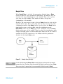
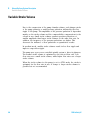
Bootp
When the initialization mode Bootp is selected, the module tries to
download the parameters from a Bootp Server. The parameters obtained
become the active parameters immediately. They are not stored to the
non- volatile memory of the module. Therefore, the parameters are lost
with the next power cycle of the module.
7ddie
HZgkZg
Figure 11
56
6Xi^kZ
EVgVbZiZg
Bootp (Principle)
1220 Infinity LC
4
LAN Configuration
Initialization mode selection
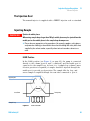
Bootp & Store
When Bootp & Store is selected, the parameters obtained from a Bootp
Server become the active parameters immediately. In addition, they are
stored to the non- volatile memory of the module. Thus, after a power
cycle they are still available. This enables a kind of bootp once
configuration of the module.
Example: The user may not want to have a Bootp Server be active in his
network all the time. But on the other side, he may not have any other
configuration method than Bootp. In this case he starts the Bootp Server
temporarily, powers on the module using the initialization mode
Bootp & Store, waits for the Bootp cycle to be completed, closes the Bootp
Server and powers off the module. Then he selects the initialization mode
Using Stored and powers on the module again. From now on, he is able to
establish the TCP/IP connection to the module with the parameters
obtained in that single Bootp cycle.
6Xi^kZ
EVgVbZiZg
7ddie
HZgkZg
Cdc"KdaVi^aZ
G6B
HidgZY
EVgVbZiZg
Figure 12
NOTE
1220 Infinity LC
Bootp & Store (Principle)
Use the initialization mode Bootp & Store carefully, because writing to the non-volatile
memory takes time. Therefore, when the module shall obtain its parameters from a Bootp
Server every time it is powered on, the recommended initialization mode is Bootp!
57
4
LAN Configuration
Initialization mode selection
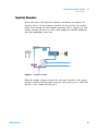
Using Stored
When initialization mode Using Stored is selected, the parameters are taken
from the non- volatile memory of the module. The TCP/IP connection will
be established using these parameters. The parameters were configured
previously by one of the described methods.
Cdc"KdaVi^aZ
G6B
6Xi^kZ
EVgVbZiZg
HidgZY
EVgVbZiZg
Figure 13
Using Stored (Principle)
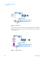
Using Default
When Using Default is selected, the factory default parameters are taken
instead. These parameters enable a TCP/IP connection to the LAN
interface without further configuration, see Table 12 on page 58.
6Xi^kZ
EVgVbZiZg
9Z[Vjai
EVgVbZiZg
Figure 14
NOTE
Using the default address in your local area network may result in network problems. Take
care and change it to a valid address immediately.
Table 12
58
Using Default (Principle)
Using Default Parameters
IP address:
192.168.254.11
Subnet Mask:
255.255.255.0
Default Gateway
not specified
1220 Infinity LC
4
LAN Configuration
Initialization mode selection
Since the default IP address is a so- called local address, it will not be
routed by any network device. Thus, the PC and the module must reside
in the same subnet.
The user may open a Telnet session using the default IP address and
change the parameters stored in the non- volatile memory of the module.
He may then close the session, select the initialization mode Using Stored,
power- on again and establish the TCP/IP connection using the new
parameters.
When the module is wired to the PC directly (e.g. using a cross- over cable
or a local hub), separated from the local area network, the user may
simply keep the default parameters to establish the TCP/IP connection.
NOTE
1220 Infinity LC
In the Using Default mode, the parameters stored in the memory of the module are not
cleared automatically. If not changed by the user, they are still available, when switching
back to the mode Using Stored.
59
4
LAN Configuration
Dynamic Host Configuration Protocol (DHCP)
Dynamic Host Configuration Protocol (DHCP)
General Information (DHCP)
The Dynamic Host Configuration Protocol (DHCP) is an auto configuration
protocol used on IP networks. The DHCP functionality is available on all
Agilent HPLC modules with on- board LAN Interface or LAN Interface
Card, and “B”- firmware (B.06.40 or above).
When the initialization mode “DHCP” is selected, the card tries to
download the parameters from a DHCP Server. The parameters obtained
become the active parameters immediately. They are not stored to the
non- volatile memory of the card.
Besides requesting the network parameters, the card also submits its
hostname to the DHCP Server. The hostname equals the MAC address of
the card, e.g. 0030d3177321. It is the DHCP server's responsibility to
forward the hostname/address information to the Domain Name Server.
The card does not offer any services for hostname resolution (e.g.
NetBIOS).
6Xi^kZ
EVgVbZiZg
9=8E
HZgkZg
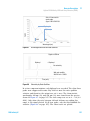
Figure 15
NOTE
DHCP (Principle)
1 It may take some time until the DHCP server has updated the DNS server with the
hostname information.
2 It may be necessary to fully qualify the hostname with the DNS suffix, e.g.
0030d3177321.country.company.com.
3 The DHCP server may reject the hostname proposed by the card and assign a name
following local naming conventions.
60
1220 Infinity LC
LAN Configuration
Dynamic Host Configuration Protocol (DHCP)
4
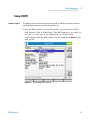
Setup (DHCP)
Software required
The modules in the stack must have at least firmware from set A.06.34 and the above mentioned
modules B.06.40 or above (must from the same firmware set).
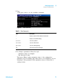
1 Note the MAC address of the LAN interface (provided with G1369C
LAN Interface Card or Main Board). This MAC address is on a label on
the card or at the rear of the main board, e.g. 0030d3177321.
On the Instant Pilot the MAC address can be found under Details in the
LAN section.
Figure 16
1220 Infinity LC
LAN Setting on Instant Pilot
61
4
LAN Configuration
Dynamic Host Configuration Protocol (DHCP)
2 Set the Configuration Switch to DHCP either on the G1369C LAN
Interface Card or the main board of above mentioned modules.
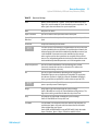
Table 13
G1369C LAN Interface Card (configuration switch on the card)
SW 4
SW 5
SW 6
SW 7
SW 8
Initialization Mode
ON
OFF
OFF
OFF
OFF
DHCP
Table 14
LC Modules inclusive 1120/1220 (configuration switch at rear of the instrument)
SW 6
SW 7
SW 8
Initialization Mode
ON
OFF
OFF
DHCP
3 Turn on the module that hosts the LAN interface.
4 Configure your Control Software (e.g. Agilent ChemStation, Lab Advisor,
Firmware Update Tool) and use MAC address as host name, e.g.
0030d3177321.
The LC system should become visible in the control software (see Note
in section “General Information (DHCP)” on page 60).
62
1220 Infinity LC
LAN Configuration
Link configuration selection
4
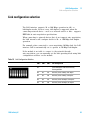
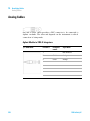
Link configuration selection
The LAN interface supports 10 or 100 Mbps operation in full- or
half- duplex modes. In most cases, full- duplex is supported when the
connecting network device - such as a network switch or hub - supports
IEEE 802.3u auto- negotiation specifications.
When connecting to network devices that do not support auto- negotiation,
the LAN interface will configure itself for 10- or 100- Mbps half- duplex
operation.
For example, when connected to a non- negotiating 10- Mbps hub, the LAN
interface will be automatically set to operate at 10- Mbps half- duplex.
If the module is not able to connect to the network through
auto- negotiation, you can manually set the link operating mode using link
configuration switches on the module.
Table 15
Link Configuration Switches
1220 Infinity LC
SW 3
SW 4
SW 5
Link Configuration
OFF
-
-
speed and duplex mode determined by
auto-negotiation
ON
OFF
OFF
manually set to 10 Mbps, half-duplex
ON
OFF
ON
manually set to 10 Mbps, full-duplex
ON
ON
OFF
manually set to 100 Mbps, half-duplex
ON
ON
ON
manually set to 100 Mbps, full-duplex
63
4
LAN Configuration
Automatic Configuration with BootP
Automatic Configuration with BootP
NOTE
All examples shown in this chapter will not work in your environment. You need your own
IP-, Subnet-Mask- and Gateway addresses.
NOTE
Assure that the detector configuration switch is set properly. The setting should be either
BootP or BootP & Store, see Table 11 on page 56.
NOTE
Assure that the detector connected to the network is powered off.
NOTE
If the Agilent BootP Service program is not already installed on your PC, then install it from
your Agilent ChemStation DVD, located in folder BootP.
About Agilent BootP Service
The Agilent BootP Service is used to assign the LAN Interface with an IP
address.
The Agilent BootP Service is provided on the ChemStation DVD. The
Agilent BootP Service is installed on a server or PC on the LAN to
provide central administration of IP addresses for Agilent instruments on
a LAN. The BootP service must be running TCP/IP network protocol and
cannot run a DHCP server.
64
1220 Infinity LC
LAN Configuration
Automatic Configuration with BootP
4
How BootP Service Works
When an instrument is powered on, an LAN Interface in the instrument
broadcasts a request for an IP address or host name and provides its
hardware MAC address as an identifier. The Agilent BootP Service
answers this request and passes a previously defined IP address and host
name associated with the hardware MAC address to the requesting
instrument.
The instrument receives its IP address and host name and maintains the
IP address as long as it is powered on. Powering down the instrument
causes it to lose its IP address, so the Agilent BootP Service must be
running every time the instrument powers up. If the Agilent BootP Service
runs in the background, the instrument will receive its IP address on
power- up.
The Agilent LAN Interface can be set to store the IP address and will not
lose the IP address if power cycled.
Situation: Cannot Establish LAN Communication
If a LAN communication with BootP service cannot be established, check
the following on the PC:
• Is the BootP service started? During installation of BootP, the service is
not started automatically.
• Does the Firewall block the BootP service? Add the BootP service as an
exception.
• Is the LAN Interface using the BootP- mode instead of "Using Stored" or
"Using Default" modes?
1220 Infinity LC
65
4
LAN Configuration
Automatic Configuration with BootP
Installation of BootP Service
Before installing and configuring the Agilent BootP Service, be sure to
have the IP addresses of the computer and instruments on hand.
1 Log on as Administrator or other user with Administrator privileges.
2 Close all Windows programs.
3 Insert the Agilent ChemStation software DVD into the drive. If the
setup program starts automatically, click Cancel to stop it.
4 Open Windows Explorer.
5 Go to the BootP directory on the Agilent ChemStation DVD and
double- click BootPPackage.msi.
6 If necessary, click the Agilent BootP Service... icon in the task bar.
7 The Welcome screen of the Agilent BootP Service Setup Wizard appears. Click
Next.
8 The End-User License Agreement screen appears. Read the terms, indicate
acceptance, then click Next.
9 The Destination Folder selection screen appears. Install BootP to the
default folder or click Browse to choose another location. Click Next.
The default location for installation is:
C:\Program Files\Agilent\BootPService\
10 Click Install to begin installation.
66
1220 Infinity LC
LAN Configuration
Automatic Configuration with BootP
4
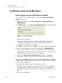
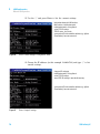
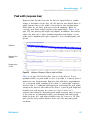
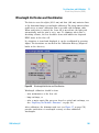
11 Files load; when finished, the BootP Settings screen appears.
Figure 17
BootP Settings screen
12 In the Default Settings part of the screen, if known, you can enter the
subnet mask and gateway.
Defaults can be used:
• The default subnet mask is 255.255.255.0
• The default gateway is 192.168.254.11
13 On the BootP Settings screen, click OK. The Agilent BootP Service Setup
screen indicates completion.
14 Click Finish to exit the Agilent BootP Service Setup screen.
15 Remove the DVD from the drive.
This completes installation.
16 Start BootP Service in the Windows® services: On the Windows®
desktop click right on Computer icon, select Manage > Services and
Applications > Services. Select the Agilent BootP Service and click Start.
1220 Infinity LC
67
4
LAN Configuration
Automatic Configuration with BootP
Two Methods to Determine the MAC Address
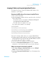
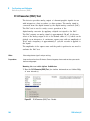
Enabling logging to discover the MAC address using BootP
If you want to see the MAC address, select the Do you want to log BootP
requests? check box.
1 Open BootP Settings from Start > All Programs > Agilent BootP Service >
EditBootPSettings.
2 In BootP Settings... check Do you want to log BootP requests? to enable logging.
Figure 18
Enable BootP logging
The log file is located in
C:\Documents and Settings\All Users\Application Data\Agilent\BootP\LogFile
It contains a MAC address entry for each device that requests
configuration information from BootP.
3 Click OK to save the values or Cancel to discard them. The editing ends.
4 After each modification of the BootP settings (i.e. EditBootPSettings) a
stop or start of the BootP service is required for the BootP service to
accept changes. See “Stopping the Agilent BootP Service” on page 72 or
“Restarting the Agilent BootP Service” on page 73.
5 Uncheck the Do you want to log BootP requests? box after configuring
instruments; otherwise, the log file will quickly fill up disk space.
Determining the MAC address directly from the LAN Interface card label
1 Turn off the instrument.
2 Read the MAC address from the label and record it.
The MAC address is printed on a label on the rear of the module. It is
the number below the barcode and after the colon (:) and usually
begins with the letters AD, see Figure 9 on page 52 and Figure 10 on
page 53.
3 Turn on the instrument.
68
1220 Infinity LC
LAN Configuration
Automatic Configuration with BootP
4
Assigning IP Addresses Using the Agilent BootP Service
The Agilent BootP Service assigns the Hardware MAC address of the
instrument to an IP address.
Determining the MAC address of the instrument using BootP Service
1 Power cycle the Instrument.
2 After the instrument completes self- test, open the log file of the BootP
Service using Notepad.
• The default location for the logfile is C:\Documents and Settings\All
Users\Application Data\Agilent\BootP\LogFile.
• The logfile will not be updated if it is open.
The contents will be similar to the following:
02/25/10 15:30:49 PM
Status: BootP Request received at outermost layer
Status: BootP Request received from hardware address: 0010835675AC
Error: Hardware address not found in BootPTAB: 0010835675AC
Status: BootP Request finished processing at outermost layer
3 Record the hardware (MAC) address (for example, 0010835675AC).
4 The Error means the MAC address has not been assigned an IP address
and the Tab File does not have this entry. The MAC address is saved to
the Tab File when an IP address is assigned.
5 Close the log file before turning on another instrument.
6 Uncheck the Do you want to log BootP requests? box after configuring
instruments to avoid having the logfile use up excessive disk space.
Adding each instrument to the network using BootP
1 Follow Start > All Programs > Agilent BootP Service and select Edit BootP
Settings. The BootP Settings screen appears.
2 Uncheck the Do you want to log BootP requests? once all instruments have
been added.
1220 Infinity LC
69
4
LAN Configuration
Automatic Configuration with BootP
The Do you want to log BootP requests? box must be unchecked when you
have finished configuring instruments; otherwise, the log file will
quickly fill up disk space.
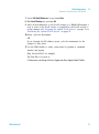
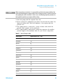
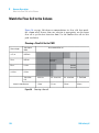
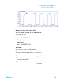
3 Click Edit BootP Addresses... The Edit BootP Addresses screen appears.
4 Click Add... The Add BootP Entry screen appears.
Figure 19
Enable BootP logging
5 Make these entries for the instrument:
• MAC address
• Host name, Enter a Hostname of your choice.
The Host Name must begin with "alpha" characters (i.e. LC1260)
• IP address
• Comment (optional)
• Subnet mask
• Gateway address (optional)
The configuration information entered is saved in the Tab File.
6 Click OK.
70
1220 Infinity LC
LAN Configuration
Automatic Configuration with BootP
4
7 Leave Edit BootP Addresses by pressing Close.
8 Exit BootP Settings by pressing OK.
9 After each modification of the BootP settings (i.e. EditBootPSettings) a
stop or start of the BootP service is required for the BootP service to
accept changes. See “Stopping the Agilent BootP Service” on page 72 or
“Restarting the Agilent BootP Service” on page 73.
10 Power cycle the Instrument.
OR
If you changed the IP address, power cycle the instrument for the
changes to take effect.
11 Use the PING utility to verify connectivity by opening a command
window and typing:
Ping 192.168.254.11 for example.
The Tab File is located at
C:\Documents and Settings\All Users\Application Data\Agilent\BootP\TabFile
1220 Infinity LC
71
4
LAN Configuration
Automatic Configuration with BootP
Changing the IP Address of an Instrument Using the Agilent BootP
Service
Agilent BootP Service starts automatically when your PC reboots. To
change Agilent BootP Service settings, you must stop the service, make the
changes, and then restart the service.
Stopping the Agilent BootP Service
1 From the Windows control panel, select Administrative Tools > Services. The
Services screen appears.
Figure 20
Windows Services screen
2 Right- click Agilent BootP Service.
3 Select Stop.
4 Close the Services and Administrative Tools screen.
Editing the IP address and other parameters in EditBootPSettings
1 Select Start > All Programs > Agilent BootP Service and select Edit BootP
Settings. The BootP Settings screen appears.
2 When the BootP Settings screen is first opened, it shows the default
settings from installation.
72
1220 Infinity LC
LAN Configuration
Automatic Configuration with BootP
4
3 Press Edit BootP Addresses… to edit the Tab File.
Figure 21
Edit BootP Adresses screen
4 In the Edit BootP Addresses... screen press Add... to create a new entry or
select an existing line from the table and press Modify... or Delete to
change the IP address, comment, subnet mask, for example, in the Tab
File.
If you change the IP address, it will be necessary to power cycle the
instrument for the changes to take effect.
5 Leave Edit BootP Addresses... by pressing Close.
6 Exit BootP Settings by pressing OK.
Restarting the Agilent BootP Service
1 In the Windows control panel, select Administrative Tools > Services. The
Services screen appears, see Figure 20 on page 72.
2 Right- click Agilent BootP Service and select Start.
3 Close the Services and Administrative Tools screens.
1220 Infinity LC
73
4
LAN Configuration
Storing the settings permanently with Bootp
Storing the settings permanently with Bootp
If you want to change parameters of the module using the Bootp follow
the instructions below.
1 Turn off the module.
2 Change the module's settings of the Configuration Switch to “Bootp &
Store” mode, see Table 11 on page 56.
3 Start the Agilent Bootp Service and open its window.
4 If required, modify the parameters for the module according to your
needs using the existing configuration.
5 Press OK to exit the Bootp Manager.
6 Now turn on the module and view the Bootp Server window. After
some time the Agilent Bootp Service will display the request from the
LAN interface. The parameters are now stored permanently in the
non- volatile memory of the module.
7 Close the Agilent Bootp Service and turn off the module.
8 Change the settings of the module’s Configuration Switch to “Using
Stored” mode, see Table 11 on page 56.
9 Power cycle the module. The module can be accessed now via LAN
without the Agilent Bootp Service.
74
1220 Infinity LC
LAN Configuration
Manual Configuration
4
Manual Configuration
Manual configuration only alters the set of parameters stored in the
non- volatile memory of the module. It never affects the currently active
parameters. Therefore, manual configuration can be done at any time. A
power cycle is mandatory to make the stored parameters become the
active parameters, given that the initialization mode selection switches are
allowing it.
I:AC:I
HZhh^dc
Cdc"KdaVi^aZ
G6B
HidgZY
EVgVbZiZg
8dcigda
BdYjaZ
Figure 22
1220 Infinity LC
Manual Configuration (Principle)
75
4
LAN Configuration
Manual Configuration
With Telnet
Whenever a TCP/IP connection to the module is possible (TCP/IP
parameters set by any method), the parameters may be altered by opening
a Telnet session.
1 Open the system (DOS) prompt window by clicking on Windows START
button and select “Run...”. Type “cmd” and press OK.
2 Type the following at the system (DOS) prompt:
• c:\>telnet <IP address> or
• c:\>telnet <host name>
Figure 23
Telnet - Starting a session
where <IP address> may be the assigned address from a Bootp cycle, a
configuration session with the Handheld Controller, or the default IP
address (see “Configuration Switches” on page 55).
When the connection was established successfully, the module responds
with the following:
Figure 24
76
A connection to the module is made
1220 Infinity LC
LAN Configuration
Manual Configuration
4
3 Type
? and press enter to see the available commands.
Figure 25
Table 16
Telnet Commands
Telnet Commands
Value
Description
?
displays syntax and descriptions of commands
/
displays current LAN settings
ip <x.x.x.x>
sets new ip address
sm <x.x.x.x>
sets new subnet mask
gw <x.x.x.x>
sets new default gateway
exit
exits shell and saves all changes
4 To change a parameter follows the style:
• parameter value, for example:
ip 134.40.27.230
Then press [Enter], where parameter refers to the configuration
parameter you are defining, and value refers to the definitions you are
assigning to that parameter. Each parameter entry is followed by a
carriage return.
1220 Infinity LC
77
4
LAN Configuration
Manual Configuration
5 Use the “/” and press Enter to list the current settings.
information about the LAN interface
MAC address, initialization mode
Initialization mode is Using Stored
active TCP/IP settings
TCP/IP status - here ready
connected to PC with controller software (e.g. Agilent
ChemStation), here not connected
Figure 26
Telnet - Current settings in "Using Stored" mode
6 Change the IP address (in this example 134.40.27.99) and type “/” to list
current settings.
change of IP setting to
Initialization mode is Using Stored
active TCP/IP settings
stored TCP/IP settings in non-volatile memory
connected to PC with controller software (e.g. Agilent
ChemStation), here not connected
Figure 27
78
Telnet - Change IP settings
1220 Infinity LC
4
LAN Configuration
Manual Configuration
7 When you have finished typing the configuration parameters, type
exit and press Enter to exit with storing parameters.
Figure 28
NOTE
1220 Infinity LC
Closing the Telnet Session
If the Initialization Mode Switch is changed now to “Using Stored” mode, the instrument
will take the stored settings when the module is re-booted. In the example above it would
be 134.40.27.99.
79
4
80
LAN Configuration
Manual Configuration
1220 Infinity LC
1220 Infinity LC
5
Solvent Delivery System Description
Overview
82
Degasser
83
Principles of Operation
84
Compressibility Compensation
Variable Stroke Volume
Using the Pump
88
90
91
This chapter provides an overview on the operational principles of the solvent
delivery system (pump and optional degasser).
Agilent Technologies
81
5
Solvent Delivery System Description
Overview
Overview
The pump is based on a two- channel, dual- plunger in- series design that
provides all essential functions that a solvent delivery system has to fulfill.
Metering of solvent and delivery to the high- pressure side are performed
by one pump assembly that can generate a pressure up to 600 bar.
The solvents are degassed by a vacuum degasser, and solvent compositions
are generated on the low- pressure side by a high- speed proportioning
valve. The dual- channel gradient pump includes a built- in dual- channel
online vacuum degasser. The isocratic pump of the Agilent 1220 Infinity
LC has no degasser.
The pump assembly includes a pump head with an inlet valve and an
outlet valve. A damping unit is connected between the two plunger
chambers. A purge valve, including a PTFE frit, is fitted at the pump
outlet for convenient priming of the pump head.
82
1220 Infinity LC
Solvent Delivery System Description
Degasser
5
Degasser
The dual- channel gradient pump comes with a built- in online degasser.
The degasser is switched on automatically when the pump is switched on,
even if the flow is set to 0 mL/min. A constant vacuum of 75 Torr
(100 mbar) is created in the vacuum chamber of the two channels. The
solvent flows through a PTFE AF tube, with an internal volume of
1.5 mL/channel inside the vacuum chamber.
1220 Infinity LC
83
5
Solvent Delivery System Description
Principles of Operation
Principles of Operation
The liquid runs from the solvent reservoir through the degasser to the
DCGV, and from there to the inlet valve. The pump assembly comprises
two substantially identical plunger/chamber units. Both plunger/chamber
units comprise a ball- screw drive and a pump head containing one
reciprocating sapphire plunger.
A servo- controlled variable- reluctance motor drives the two ball- screw
drives in opposite directions. The gears for the ball- screw drives have
different circumferences (ratio 2:1), allowing the first plunger to move at
twice the speed of the second plunger. The solvent enters the pump head
close to the bottom limit and leaves it at its top. The outer diameter of
the plunger is smaller than the inner diameter of the pump head chamber,
allowing the solvent to fill the gap in between. The first plunger has a
stroke volume in the range of 20 – 100 µL depending on the flow rate.
The microprocessor controls all flow rates in a range of
1 µL/min–10 mL/min. The inlet of the first plunger/chamber unit is
connected to the inlet valve, which is opened or closed allowing solvent to
be drawn into the first plunger pump unit.
The outlet of the first plunger/chamber unit is connected through the
outlet ball valve and the damping unit to the inlet of the second
plunger/chamber unit. The outlet of the purge valve assembly is then
connected to the chromatographic system.
84
1220 Infinity LC
Solvent Delivery System Description
Principles of Operation
5
9VbeZg
8]VbWZg'
8]VbWZg&
Ejg\ZkVakZ
>caZikVakZ
IdXdajbc
DjiaZi
kVakZ
IdlVhiZ
;gdbhdakZciWdiiaZ
HZVa
Eajc\Zg&
Eajc\Zg'
7VaahXgZlYg^kZ
<ZVg
Bdidgl^i]ZcXdYZg
Figure 29
1220 Infinity LC
Principle of the pump
85
5
Solvent Delivery System Description
Principles of Operation
When turned on, the pump runs through an initialization procedure to
determine the upper dead center of the first plunger. The first plunger
moves slowly upwards into the mechanical stop of chamber, and from
there it moves back a predetermined distance. The controller stores this
plunger position in memory. After this initialization, the pump starts
operation with the set parameters. The inlet valve is opened and the
down- moving plunger draws solvent into the first chamber. At the same
time, the second plunger moves upwards, delivering into the system. After
a controller- defined stroke length (depending on the flow rate), the drive
motor is stopped and the inlet valve is closed. The motor direction is
reversed and moves the first plunger up until it reaches the stored upper
limit and at the same time moves the second plunger downwards. The
sequence then starts again, moving the plungers up and down between the
two limits. During the up movement of the first plunger, the solvent in the
chamber is pushed through the outlet ball valve into the second chamber.
The second plunger draws in half of the volume displaced by the first
plunger and the remaining half volume is directly delivered into the
system. During the drawing stroke of the first plunger, the second plunger
delivers the drawn volume into the system.
For solvent compositions from the solvent bottles A and B, the controller
divides the length of the intake stroke into certain fractions in which the
gradient valve connects the specified solvent channel to the pump input.
Table 17
Isocratic pump details
Dead volume
800 – 1100 µL, depending on back pressure
Materials in contact with mobile phase
86
Pump head
SST, gold, sapphire, ceramic
Active inlet valve
SST, gold, sapphire, ruby, ceramic, PTFE
Outlet valve
SST, gold, sapphire, ruby
Adapter
SST, gold
Purge valve
SST, gold, PTFE, ceramic, PEEK
Degasser chamber
TFE/PDD copolymer, FEP, PEEK, PPS
1220 Infinity LC
Solvent Delivery System Description
Principles of Operation
Table 18
5
Gradient pump details
Delay volume
800 – 1100 µL, dependent on back pressure
Materials in contact with mobile phase
1220 Infinity LC
MCGV
PTFE
Pump head
SST, gold, sapphire, ceramic
Active inlet valve
SST, gold, sapphire, ruby, ceramic, PTFE
Outlet valve
SST, gold, sapphire, ruby
Adapter
SST, gold
Purge valve
SST, gold, PTFE, ceramic, PEEK
Damping unit
Gold, SST
Degasser chamber
TFE/PDD copolymer, FEP, PEEK, PPS
87
5
Solvent Delivery System Description
Compressibility Compensation
Compressibility Compensation
Principles of compressibility compensation
The compressibility of the solvents in use affects retention- time stability
when the back pressure in the system changes (for example, ageing of the
column). To minimize this effect, the pump provides a compressibility
compensation feature that optimizes the flow stability according to the
solvent type. The compressibility compensation is set to a default value
and can be changed through the user interface.
Without compressibility compensation, the following happens during a
stroke of the first plunger: the pressure in the plunger chamber increases
and the volume in the chamber is compressed, depending on backpressure
and solvent type. The volume displaced into the system is reduced by the
compressed volume.
When a compressibility value is set, the processor calculates a
compensation volume that is depending on the backpressure in the system
and the selected compressibility. This compensation volume is added to
the normal stroke volume and compensates for the previously described
loss of volume during the delivery stroke of the first plunger.
Optimizing the compressibility compensation setting
The default compressibility compensation setting is 46·10- 6 /bar. This
setting represents an average value. Under normal conditions, the default
setting reduces the pressure pulsation to values (below 1 % of system
pressure) that are sufficient for most applications and for all gradient
analyses. For applications using sensitive detectors, the compressibility
settings can be optimized by using the values for the various solvents. If
the solvent in use is not listed in the compressibility tables, when using
isocratic mixtures of solvents and if the default settings are not sufficient
for your application, the following procedure can be used to optimize the
compressibility settings.
88
1220 Infinity LC
Solvent Delivery System Description
Compressibility Compensation
NOTE
5
When using mixtures of solvents, it is not possible to calculate the compressibility of the
mixture by interpolating the compressibility values of the pure solvents used in that mixture
or by applying any other calculation. In these cases, the following empirical procedure has
to be applied to optimize your compressibility setting.
1 Start the pump with the required flow rate.
2 Before starting the optimization procedure, the flow must be stable. Use
degassed solvent only. Check the tightness of the system with the
pressure test.
3 Your pump must be connected to control software with which the
pressure and %- ripple can be monitored.
4 The compressibility compensation setting that generates the smallest
pressure ripple is the optimum value for your solvent composition.
Table 19
1220 Infinity LC
Solvent Compressibility
Solvent (pure)
Compressibility (1·10-6 /bar)
Acetone
126
Acetonitrile
115
Benzene
95
Carbon tetrachloride
110
Chloroform
100
Cyclohexane
118
Ethanol
114
Ethyl acetate
104
Heptane
120
Hexane
150
Isobutanol
100
Isopropanol
100
Methanol
120
1-Propanol
100
Toluene
87
Water
46
89
5
Solvent Delivery System Description
Variable Stroke Volume
Variable Stroke Volume
Due to the compression of the pump- chamber volume, each plunger stroke
of the pump generates a small pressure pulsation, influencing the flow
ripple of the pump. The amplitude of the pressure pulsation is dependent
mainly on the stroke volume and the compressibility compensation for the
solvent in use. Small stroke volumes generate pressure pulsations of
smaller amplitude than larger stroke volumes at the same flow rate. In
addition, the frequency of the pressure pulsations are higher. This
decreases the influence of flow pulsations on quantitative results.
In gradient mode, smaller stroke volumes result in less flow ripple and
improve composition ripple.
The pump uses a processor- controlled spindle system to drive its plungers.
The normal stroke volume is optimized for the selected flow rate. Low
flow rates use a small stroke volume, while higher flow rates use a larger
stroke volume.
When the stroke volume for the pump is set to AUTO mode, the stroke is
optimized for the flow rate in use. A change to larger stroke volumes is
possible but not recommended.
90
1220 Infinity LC
5
Solvent Delivery System Description
Using the Pump
Using the Pump
Hints for successful use of the Agilent 1220 Infinity LC pump
• When using salt solutions and organic solvents in the Agilent 1120
Infinity LC pump, it is recommended to connect the salt solution to one
of the lower gradient valve ports and the organic solvent to one of the
upper gradient valve port. It is best to have the organic channel directly
above the salt solution channel. Regular flushing with water of all
DCGV channels is recommended to remove all possible salt deposits in
the valve ports.
• Before operating the pump, flush the vacuum degasser (optional) with
at least two volumes (3 mL), especially when the pump has been turned
off for some time (for example, overnight) and volatile solvent mixtures
are used in the channels.
• Prevent blocking of solvent inlet filters (never use the pump without
solvent inlet filter). Growth of algae should be avoided.
• Check the purge valve frit and column frit regularly. A blocked purge
valve frit can be identified by black or yellow layers on its surface, or
by a pressure greater than 10 bar when pumping distilled water at a
rate of 5 mL/min with an open purge valve.
• When using the pump at low flow rates (for example, 0.2 mL/min),
check all 1/16- inch fittings for any signs of leaks.
• When exchanging the pump seals, also exchange the purge valve frit.
• When using buffer solutions, flush the system with water before
switching it off.
• Check the pump plungers for scratches when changing the plunger
seals. Scratched plungers will lead to micro leaks and will decrease the
lifetime of the seal.
• After changing the plunger seals, pressurize the system according to the
wear- in procedure.
1220 Infinity LC
91
5
Solvent Delivery System Description
Using the Pump
Preventing blockage of solvent filters
Contaminated solvents or algae growth in the solvent bottle will reduce
the lifetime of the solvent filter and will influence the performance of the
pump. This is especially true for aqueous solvents or phosphate buffers
(pH 4 – 7). The following suggestions will prolong the lifetime of the
solvent filter and will maintain the performance of the pump.
• Use a sterile, if possible amber, solvent bottle to slow down algae
growth.
• Filter solvents through filters or membranes that remove algae.
• Exchange solvents every two days, or refilter.
• If the application permits, add 0.0001 – 0.001 M sodium azide to the
solvent.
• Place a layer of argon on top of your solvent.
• Avoid exposing the solvent bottle to direct sunlight.
NOTE
92
Never use the system without a solvent filter installed.
1220 Infinity LC
1220 Infinity LC
6
Injection System Description
Manual Injector 94
The Injection Seal 95
Injecting Sample 95
Needles 96
Autosampler 97
Sampling Sequence 98
Injection Sequence 99
Sampling Unit 101
Needle-Drive 102
Analytical head 102
Injection Valve 103
Transport Assembly 104
Supported Trays for the Autosampler
Choice of Vials and Caps 106
105
This chapter provides an overview of the operational principles of the injection
systems: manual injector and autosampler.
Agilent Technologies
93
6
Injection System Description
Manual Injector
Manual Injector
The Agilent 1220 Infinity LC manual injector uses a Rheodyne, 6- port
sample injection valve (5067- 4202). Sample is loaded into the external
20 µL sample loop through the injection port at the front of the valve. The
valve has a PEEK™ injection seal. A make- before- break passage in the
stator ensures flow is not interrupted when the valve is switched between
the INJECT and LOAD positions, and back again.
AdVYedh^i^dc
>c_ZXiedh^i^dc
Figure 30
94
Rheodyne 6-port sample injection valve
1220 Infinity LC
6
Injection System Description
Manual Injector
The Injection Seal
The manual injector is supplied with a PEEK™ injection seal as standard.
Injecting Sample
WA R N I N G
Ejection of mobile phase
When using sample loops larger than 100 µL, mobile phase may be ejected from the
needle port as the mobile phase in the sample loop decompresses.
➔ Please observe appropriate safety procedures (for example, goggles, safety gloves
and protective clothing) as described in the material handling and safety data sheet
supplied by the solvent vendor, especially when toxic or hazardous solvents are
used.
LOAD Position
In the LOAD position (see Figure 31 on page 95), the pump is connected
directly to the column (ports 4 and 5 connected), and the needle port is
connected to the sample loop. At least 2 to 3 sample- loop volumes (more
if better precision is required) of sample should be injected through the
needle port to provide good precision. The sample fills the loop, and
excess sample is expelled through the vent tube connected to port 2.
CZZYaZedgi
LVhiZ
idXdajbc
[gdbejbe
HVbeaZadde
Figure 31
1220 Infinity LC
LOAD Position
95
6
Injection System Description
Manual Injector
INJECT Position
In the INJECT position (see Figure 32 on page 96), the pump is connected
to the sample loop (ports 5 and 6 connected). All of the sample is washed
out of the loop onto the column. The needle port is connected to the vent
tube (port 2).
CZZYaZedgi
LVhiZ
[gdbejbe
idXdajbc
HVbeaZadde
Figure 32
INJECT Position
Needles
CAUTION
Needle can damage valve
➔ Always use the correct needle size.
Use needles with 0.028- inch outer diameter (22 gauge) × 2- inch long
needle, without electro- taper, and with 90° point style (square tip).
96
1220 Infinity LC
Injection System Description
Autosampler
6
Autosampler
Three sample- rack sizes are available for the autosampler. The standard
full- size rack holds 100 × 1.8 mL vials, while the two half- size racks
provide space for 40 × 1.8 mL and 15 × 6 mL vials respectively. Any two
half- size rack trays can be installed in the autosampler simultaneously.
The analytical head device provides injection volumes from 0.1 – 100 µL.
The autosamplers transport mechanism uses an X- Z- Theta movement to
optimize vial pick- up and return. Vials are picked up by the gripper arm,
and positioned below the sampling unit. The gripper transport mechanism
and sampling unit are driven by motors. Movement is monitored by optical
sensors and optical encoders to ensure correct operation. The metering
device is always flushed after injection to ensure minimum carry- over.
The six- port injection valve unit (only 5 ports are used) is driven by a
high- speed hybrid stepper motor. During the sampling sequence, the valve
unit bypasses the autosampler, and directly connects the flow from the
pump to the column. During injection and analysis, the valve unit directs
the flow through the autosamplers which ensures that the sample is
injected completely into the column, and that any sample residue is
removed from the metering unit and needle from before the next sampling
sequence begins.
1220 Infinity LC
97
6
Injection System Description
Autosampler
Sampling Sequence
The movements of the autosampler components during the sampling
sequence are monitored continuously by the processor. The processor
defines specific time windows and mechanical ranges for each movement.
If a specific step of the sampling sequence can’t be completed successfully,
an error message is generated.
Solvent is bypassed from the autosamplers by the injection valve during
the sampling sequence. The sample vial is selected by a gripper arm from
a static sample rack. The gripper arm places the sample vial below the
injection needle. The required volume of sample is drawn into the sample
loop by the metering device. Sample is applied to the column when the
injection valve returns to the mainpass position at the end of the sampling
sequence.
The sampling sequence occurs in the following order:
1 The injection valve switches to the bypass position.
2 The plunger of the metering device moves to the initialization position.
3 The gripper arm selects the vial. At the same time, the needle lifts out
of the seat.
4 The gripper arm places the vial below the needle.
5 The needle lowers into the vial.
6 The metering device draws the defined sample volume.
7 The needle lifts out of the vial.
8 If the automated needle wash is selected, the gripper arm replaces the
sample vial, positions the wash vial below the needle, lowers the needle
into the vial, then lifts the needle out of the wash vial.
9 The gripper arm checks if the safety flap is in position.
10 The gripper arm replaces the vial. Simultaneously, the needle lowers
into the seat.
11 The injection valve switches to the mainpass position.
98
1220 Infinity LC
6
Injection System Description
Autosampler
Injection Sequence
Before the start of the injection sequence, and during an analysis, the
injection valve is in the mainpass position. In this position, the mobile
phase flows through the autosamplers metering device, sample loop, and
needle, ensuring all parts in contact with sample are flushed during the
run, thus minimizing carry- over.
Figure 33
Mainpass Position
When the sample sequence begins, the valve unit switches to the bypass
position. Solvent from the pump enters the valve unit at port 1, and flows
directly to the column through port 6.
1220 Infinity LC
99
6
Injection System Description
Autosampler
Figure 34
Bypass Position
Next, the needle is raised, and the vial is positioned below the needle. The
needle moves down into the vial, and the metering unit draws the sample
into the sample loop.
Figure 35
100
Drawing the Sample
1220 Infinity LC
Injection System Description
Autosampler
6
When the metering unit has drawn the required volume of sample into the
sample loop, the needle is raised, and the vial is replaced in the sample
tray. The needle is lowered into the needle seat, and the injection valve
switches back to the mainpass position, flushing the sample onto the
column .
Figure 36
Mainpass Position (Sample Injection)
Sampling Unit
The sampling unit comprises three main assemblies: needle drive, metering
device, and injection valve.
NOTE
1220 Infinity LC
The replacement sampling unit excludes the injection valve and metering head assemblies.
101
6
Injection System Description
Autosampler
Needle-Drive
The needle movement is driven by a stepper motor connected to the
spindle assembly by a toothed belt. The circular motion of the motor is
converted to linear motion by the drive nut on the spindle assembly. The
upper and lower needle positions are detected by reflection sensors on the
sampling unit flex board, while the needle- in- vial position is determined
by counting the motor steps from the upper needle- sensor position.
Analytical head
The analytical head is driven by the stepper motor connected to the drive
shaft by a toothed belt. The drive nut on the spindle converts the circular
movement of the spindle to linear motion. The drive nut pushes the
sapphire plunger against the tension of the spring into the analytical head.
The base of the plunger sits on the large bearing of the drive nut, which
ensures the plunger is always centered. A ceramic ring guides the
movement of the plunger in the analytical head. The home position of the
plunger is sensed by an infra- red sensor on the sampling unit flex board,
while the sample volume is determined by counting the number of steps
from the home position. The backward movement of the plunger (driven
by the spring) draws sample from the vial.
Table 20
Analytical head technical data
Standard (100 µL)
102
Number of steps
15000
Volume resolution
7 nL/motor step
Maximum stroke
100 µL
Pressure limit
600 bar
Plunger material
Sapphire
1220 Infinity LC
Injection System Description
Autosampler
6
Injection Valve
The two- position 6- port injection valve is driven by a stepper motor. Only
five of the six ports are used (port 3 is not used). A lever/slider
mechanism transfers the movement of the stepper motor to the injection
valve. Two microswitches monitor switching of the valve (bypass and
mainpass end positions).
No valve adjustments are required after replacing internal components.
Table 21
Injection valve technical data
Standard
1220 Infinity LC
Motor type
4 V, 1.2 A stepper motor
Seal material
Vespel™ (Tefzel™ available)
Number of ports
6
Switching time
< 150 ms
103
6
Injection System Description
Autosampler
Transport Assembly
The transport unit comprises an X- axis slide (left- right motion), a Z- axis
arm (up- down motion), and a gripper assembly (rotation and
vial- gripping).
Mbdidg
I]ZiVbdidg
<g^eeZgbdidg
MVm^h
<g^eeZg
I]ZiVVm^h
OVm^h
Obdidg
;aZmWdVgY
Figure 37
Transport Assembly
The transport assembly uses four stepper motors driven in closed- loop
mode for accurate positioning of the gripper assembly for sample- vial
transport. The rotational movement of the motors is converted to linear
motion (X- and Z- axes) by toothed belts connected to the drive spindles.
The rotation (theta axes) of the gripper assembly is transferred from the
motor by a toothed belt and series of gears. The opening and closing of
the gripper fingers are driven by a stepper motor linked by a toothed belt
to the planetary gearing inside the gripper assembly.
104
1220 Infinity LC
6
Injection System Description
Autosampler
The stepper motor positions are determined by the optical encoders
mounted onto the stepper- motor housing. The encoders monitor the
position of the motors continually, and correct for position errors
automatically (e.g. if the gripper is accidentally moved out of position
when loading vials into the vial tray). The initialization positions of the
moving components are sensed by reflection sensors mounted on the flex
board. These positions are used by the processor to calculate the actual
motor position. An additional six reflection sensors for tray recognition
are mounted on the flex board at the front of the assembly.
Supported Trays for the Autosampler
p/n
Description
G1313-44510
Tray for 100 x 2 mL vials
G1313-44513
Halftray for 15 x 6 mL vials
G1313-44512
Halftray for 40 x 2 mL vials
Half-tray combinations
Half- trays can be installed in any combination enabling both 2 mL- and
6 mL- vials to be used simultaneously.
Numbering of vial positions
The standard 100- vial tray has vial positions 1 to 100. However, when
using two half- trays, the numbering convention is slightly different. The
vial positions of the right- hand half tray begin at position 101 as follows:
Left- hand 40- position tray: 1 – 40
Left- hand 15- position tray: 1 – 15
Right- hand 40- position tray: 101 – 140
Right- hand 15- position tray: 101 – 115
1220 Infinity LC
105
6
Injection System Description
Autosampler
Choice of Vials and Caps
For reliable operation, vials used with the Agilent 1220 Infinity LC
autosampler must not have tapered shoulders or caps that are wider than
the body of the vial. The vials and caps shown with their part numbers in
the tables below have been successfully tested using a minimum of 15000
injections with the Agilent 1220 Infinity LC autosampler.
Crimp top vials
106
p/n
Description
5181-3375
Crimp Top Vial, 2 mL, clear glass, 100/Pack
5183-4491
Crimp Top Vial, 2 mL, clear glass, 1000/Pack
5182-0543
Crimp Top Vial, 2 mL, clear glass, write-on spot, 100/Pack
5183-4492
Crimp Top Vial, 2 mL, clear glass, write-on spot, 1000/Pack
5183-4494
Crimp Top Vial, 2 mL, clear glass, write-on spot, 100/Pack (silanized)
5181-3376
Crimp Top Vial, 2 mL, amber glass, write-on spot, 100/Pack
5183-4493
Crimp Top Vial, 2 mL, amber glass, write-on spot, 1000/Pack
5183-4495
Crimp Top Vial, 2 mL, amber glass, write-on spot, 100/Pack
(silanized)
5182-0567
Crimp Top Vial, 1 mL, polypropylene, wide opening, 100/Pack
5183-4496
Crimp Top Vial, 1 mL, polypropylene, wide opening, 100/Pack
(silanized)
9301-0978
crimp top vial, 0.3 mL, polypropylene, wide opening, 1000/pack
1220 Infinity LC
Injection System Description
Autosampler
6
Snap top vials
p/n
Description
5182-0544
Snap Top Vial, 2 mL, clear glass, 100/Pack
5183-4504
Snap Top Vial, 2 mL, clear glass, 1000/Pack
5183-4507
Snap Top Vial, 2 mL, clear glass, 100/Pack (silanized)
5182-0546
Snap Top Vial, 2 mL, clear glass, write-on spot, 100/Pack
5183-4505
Snap Top Vial, 2 mL, clear glass, write-on spot, 1000/Pack
5183-4508
Snap Top Vial, 2 mL, clear glass, write-on spot, 100/Pack (silanized)
5182-0545
Snap Top Vial, 2 mL, amber glass, write-on spot, 100/Pack
5183-4506
Snap Top Vial, 2 mL, amber glass, write-on spot, 1000/Pack
5183-4509
Snap Top Vial, 2 mL, amber glass, write-on spot, 100/Pack
(silanized)
Screw top vials
1220 Infinity LC
p/n
Description
5182-0714
Screw Cap Vials, 2 mL, clear glass, 100/Pack
5183-2067
Screw Top Vial, 2 mL, clear glass, 1000/Pack
5183-2070
Screw Top Vial, 2 mL, clear glass, 100/Pack (silanized)
5182-0715
Screw Top Vial, 2 mL, clear glass, write-on spot, 100/Pack
5183-2068
Screw Top Vial, 2 mL, clear glass, write-on spot, 1000/Pack
5183-2071
Screw Top Vial, 2 mL, clear glass, write-on spot, 100/Pack
(silanized)
5182-0716
Screw Cap Vial, 2 mL, amber glass, write-on spot, 100/pk
5183-2069
Screw Top Vial, 2 mL, amber glass, write-on spot, 1000/Pack
5183-2072
Screw Top Vial, 2 mL, amber glass, write-on spot, 100/Pack
(silanized)
107
6
Injection System Description
Autosampler
Crimp caps
p/n
Description
5181-1210
Crimp Cap, silver aluminum, septum (clear PTFE/red rubber), 100/Pack
5183-4498
Crimp Cap, silver aluminum, septum (clear PTFE/red rubber), 1000/Pack
5181-1215
Crimp Cap, blue aluminum, septum (clear PTFE/red rubber), 100/Pack
5181-1216
Crimp Cap, green aluminum, septum (clear PTFE/red rubber), 100/Pack
5181-1217
Crimp Cap, red aluminum, septum (clear PTFE/red rubber), 100/Pack
Snap caps
p/n
Description
5182-0550
Snap Cap, clear polypropylene, septum (clear PTFE/red rubber), 100/Pack
5182-3458
Snap Cap, blue polypropylene, septum (clear PTFE/red rubber), 100/Pack
5182-3457
Snap Cap, green polypropylene, septum (clear PTFE/red rubber), 100/Pack
5182-3459
Snap Cap, red polypropylene, septum (clear PTFE/red rubber), 100/Pack
Screw caps
108
p/n
Description
5182-0717
Screw Cap, blue polypropylene, septum (clear PTFE/red rubber), 100/Pack
5182-0718
Screw Cap, green polypropylene, septum (clear PTFE/red rubber), 100/Pack
5182-0719
Screw Cap, red polypropylene, septum (clear PTFE/red rubber), 100/Pack
5182-0720
Screw Cap, blue polypropylene, septum (clear PTFE/silicone), 100/Pack
5182-0721
Screw Cap, green polypropylene, septum (clear PTFE/silicone), 100/Pack
5182-0722
Screw Cap, red polypropylene, septum (clear PTFE/silicone), 100/Pack
1220 Infinity LC
1220 Infinity LC
7
Column Oven Description
Column Oven
110
This chapter provides an overview of the operational principles of the column
oven.
Agilent Technologies
109
7
Column Oven Description
Column Oven
Column Oven
The column oven is based on a resistor heater matt with two thermal
sensors to provide constant temperature in the whole column area. A
built- in over temperature cut off fuse inhibits overheating.
The inner volume of the oven capillary is 6 µL.
Maximum column length is 25 cm (10 inch).
Operational range is 5 ° above ambient, at least 10 °C up to 60 °C, max.
specified flow rate is 5 mL/min at 60 °C.
NOTE
110
Never operate the column oven with open front cover, to ensure a correct column
temperature always operate with closed front cover. The counterpart of the oven isolation
is fixed at the inner side of the front cover.
1220 Infinity LC
1220 Infinity LC
8
Detector Description
Detector Types
112
Agilent 1220 Infinity LC Variable Wavelength Detector (VWD)
Detector 113
113
Agilent 1220 Infinity LC Diode Array Detector (DAD) 114
Introduction to the Detector 114
Optical System 115
Peak width (response time) 117
Sample and Reference Wavelength and Bandwidth 119
Slit Width 122
Optimizing Spectral Acquisition (DAD only) 124
Margin for Negative Absorbance 124
Optimizing Selectivity 125
Spectrum Settings (DAD only) 128
Match the Flow Cell to the Column
130
This chapter provides an overview of the operational principles of the detector.
Agilent Technologies
111
8
Detector Description
Detector Types
Detector Types
There are two different detector types available for the Agilent 1220
Infinity LC System:
• Variable Wavelength Detector (VWD, used in G4286B, G4288B/C,
G4290B/C), optical unit of the G1314F VWD
• Diode Array Detector (DAD, used in G4294B), optical unit of the
G1315C DAD
112
1220 Infinity LC
8
Detector Description
Agilent 1220 Infinity LC Variable Wavelength Detector (VWD)
Agilent 1220 Infinity LC Variable Wavelength Detector (VWD)
Detector
The Agilent 1220 Infinity LC variable wavelength detector is designed for
highest optical performance, GLP compliance and easy maintenance, with:
• Deuterium lamp for highest intensity and lowest detection limit over a
wavelength range of 190 – 600 nm,
• Optional flow- cell cartridges (standard: 10 mm14 µL, high pressure:
10 mm14 µL, micro: 3 mm2 µL, semi- micro: 6 mm5 µL) are available
and can be used depending on the application needs,
• Easy front access to lamp and flow cell for fast replacement, and
• Built- in holmium oxide filter for fast wavelength accuracy verification.
1220 Infinity LC
113
8
Detector Description
Agilent 1220 Infinity LC Diode Array Detector (DAD)
Agilent 1220 Infinity LC Diode Array Detector (DAD)
Introduction to the Detector
The detector is designed for highest optical performance, GLP compliance
and easy maintenance. It includes the following features:
• 80 Hz data acquisition rate for (ultra- ) fast LC applications
• RFID tags for all flow cells and UV- lamps provides traceable
information about these assemblies
• Long- life deuterium with RFID tag and tungsten lamps for highest
intensity and lowest detection limit over a wavelength range of 190 –
950 nm
• No loss in sensitivity for up to eight wavelengths simultaneous
• Programmable slit from 1 – 16 nm for complete optimization of
sensitivity, linearity and spectral resolution
• Optional flow- cell cartridges with RFID tag (standard 10 mm13 µL,
semi- micro 6 mm5 µL, micro 3 mm2 µL, 80 nL, 500 nL, 10 mm, high
pressure 10 mm1.7 µL and prep- cells) are available and can be used
depending on the application needs.
• Easy front access to lamps and flow cell for fast replacement
• Built- in holmium oxide filter for fast wavelength accuracy verification
• Built- in temperature control for improved baseline stability
• Additional diagnostic signals for temperature and lamp voltage
monitoring
For specifications, see “Performance Specifications Agilent 1220 Infinity
LC DAD” on page 26.
114
1220 Infinity LC
Detector Description
Agilent 1220 Infinity LC Diode Array Detector (DAD)
8
Optical System
The optical system of the detector is shown in Figure below. Its
illumination source is a combination of a deuterium- arc- discharge lamp
for the ultraviolet (UV) wavelength range and a tungsten lamp for the
visible (VIS) and short- wave near- infrared (SWNIR) wavelength range. The
image of the filament of the tungsten lamp is focused on the discharge
aperture of the deuterium lamp by means of a special rear- access lamp
design which allows both light sources to be optically combined and share
a common axis to the source lens. The achromat (source lens) forms a
single, focused beam of light through the flow cell. Each cell room and
lamp are separated by a quartz window which can be cleaned or replaced.
In the spectrograph, light is being dispersed onto the diode array by a
holographic grating. This allows simultaneous access to all wavelength
information.
8Zaahjeedgil^cYdl
Ijc\hiZcaVbe
8djea^c\aZch
9ZjiZg^jbaVbe
6X]gdbVihdjgXZaZch
=dab^jbdm^YZ[^aiZg
;adlXZaa
HeZXigdaZch
Ha^i
<gVi^c\
9^dYZVggVn
Figure 38
Lamps
1220 Infinity LC
Optical System of the Detector
The light source for the UV- wavelength range is a deuterium lamp with a
shine- through aperture. As a result of plasma discharge in low- pressure
deuterium gas, the lamp emits light over the 190 nm to approximately 800
nm wavelength range. The light source for the visible and SWNIR
wavelength range is a low noise tungsten lamp. This lamp emits light over
the wavelength range 470 – 950 nm.
115
8
Detector Description
Agilent 1220 Infinity LC Diode Array Detector (DAD)
Achromat
(Source Lens)
Holmium Oxide
Filter
The achromat receives the light from both lamps and focuses it so that the
beam passes through the flow cell.
The holmium oxide filter is electromechanically actuated. During the
holmium filter test it moves into the light path.
Cell Support
Window
The cell support window assembly separates the holmium filter area from
the flow cell area.
Flow Cell
Compartment
The optical unit has a flow cell compartment for easy access to flow cells.
A variety of optional flow cells can be inserted using the same quick,
simple mounting system. The flow cell can be removed to check the optical
and electronic performance of the detector without having influences from
the flow cell.
Spectrograph
The spectrograph material is ceramic to reduce thermal effects to a
minimum. The spectrograph consists of the spectrograph lens, the variable
entrance slit, the grating and the photodiode array with front- end
electronics. The spectrograph lens refocuses the light beam after it has
passed through the flow cell. The sampling interval of the diode array is
< 1 nm over the wavelength range 190 – 950 nm. Depending on the
wavelength this varies from 1.0 to 1.25 diodes per nanometer (for example
a diode every 0.8 to 1 nm).
For a small wavelength range, the small non- linearity could be neglected.
With the wavelength range from 190 – 950 nm a new approach is required
to achieve wavelength accuracy over the full range. Each spectrograph is
calibrated individually. The calibration data is stored in the spectrograph
on an EEPROM. Based on these data, the built- in processors calculate
absorbance data with linear intervals (1.0, 2.0, …) between data points.
This results in an excellent wavelength accuracy and
instrument- to- instrument reproducibility.
Variable Entrance
Slit System
Grating
Diode Array
116
The micro- slit system makes use of the mechanical properties of silicon
combined with the precise structuring capabilities of bulk
micro- machining. It combines the required optical functions — slit and
shutter — in a simple and compact component. The slit width is directly
controlled by the micro- processor of the instrument and can be set as
method parameter.
The combination of dispersion and spectral imaging is accomplished by
using a concave holographic grating. The grating separates the light beam
into all its component wavelengths and reflects the light onto the
photodiode array.
The diode array is a series of 1024 individual photodiodes and control
circuits located on a ceramic carrier. With a wavelength range from
190 – 950 nm the sampling interval is < 1 nm.
1220 Infinity LC
8
Detector Description
Agilent 1220 Infinity LC Diode Array Detector (DAD)
Peak width (response time)
Response time describes how fast the detector signal follows a sudden
change of absorbance in the flow cell. The detector uses digital filters to
adapt response time to the width of the peaks in your chromatogram.
These filters do not affect peak area nor peak symmetry. When set
correctly, such filters reduce baseline noise significantly ( Figure 39 on
page 117), but reduce peak height only slightly. In addition, these filters
reduce the data rate to allow optimum integration and display of your
peaks and to minimize disk space required to store chromatograms and
spectra.
Jc[^aiZgZY
GZhedchZi^bZ
%#%*b^c
GZhedchZi^bZ
%#&b^c
Figure 39
Influence of Response Time on Signal and Noise
Table 22 on page 118 lists the filter choices of the detector. To get
optimum results, set peak width as close as possible to a narrow peak of
interest in your chromatogram. Response time will the be approximately
1/3 of the peak width, resulting in less than 5 % peak- height reduction
and less than 5 % additional peak dispersion. Decreasing the peak width
setting in the detector will result in less than 5 % gain in peak height but
baseline noise will increase by a factor of 1.4 for a factor of 2
response- time reduction. Increasing peak width (response time) by factor
of two from the recommended setting (over- filtering) will reduce peak
height by about 20 % and reduce baseline noise by a factor of 1.4. This
gives you the best possible signal- to- noise ratio, but may affect peak
resolution.
1220 Infinity LC
117
8
Detector Description
Agilent 1220 Infinity LC Diode Array Detector (DAD)
Table 22
118
Peak Width — Response Time — Data Rate
Peak Width [minutes]
Response Time [seconds]
Data Rate [Hz]
<0.0025
0.025
80
>0.0025
0.05
80
>0.005
0.1
40
>0.01
0.2
20
>0.03
0.5
10
>0.05
1.0
5
>0.10
2.0
2.5
>0.20
4.0
1.25
>0.40
8.0
0.62
>0.85
16.0
0.31
1220 Infinity LC
8
Detector Description
Agilent 1220 Infinity LC Diode Array Detector (DAD)
Sample and Reference Wavelength and Bandwidth
The detector measures absorbance simultaneously at wavelengths from 190
to 950 nm. Two lamps provide good sensitivity over the whole wavelength
range. The deuterium discharge lamp provides the energy for the UV range
(190 to 400 nm) and the tungsten lamp emits light from 400 to 950 nm
for the visible and short wave near infrared.
If you know little about the analytes in your sample, use both lamps and
store all spectra over the full wavelength range. This provides full
information but fills up your disk space rather quickly. Spectra can be
used to check a peak’s purity and identity. Spectral information is also
useful to optimize wavelength settings for your chromatographic signal.
The detector can compute and store at run time up to 8 signals with these
properties:
• sample wavelength, the center of a wavelength band with the width of
sample bandwidth (BW), and optionally
• reference wavelength, the center of a wavelength band with the width
of reference bandwidth.
The signals comprises a series of data points over time, with the average
absorbance in the sample wavelength band minus the average absorbance
of the reference wavelength band.
Signal A in the detector default method is set to sample 250,100, reference
360,100, that is, the average absorbance from 200 – 300 nm minus the
average absorbance from 300 – 400 nm. As all analytes show higher
absorbance at 200 – 300 nm than at 300 – 400 nm, this signal will show
you virtually every compound which can be detected by UV absorbance.
Many compounds show absorbance bands in the spectrum. Figure 40 on
page 120 shows the spectrum of anisic acid as an example.
To optimize for lowest possible detectable concentrations of anisic acid, set
the sample wavelength to the peak of the absorbance band (that is,
252 nm) and the sample bandwidth to the width of the absorbance band
(that is, 30 nm). A reference of 360,100 is adequate. Anisic acid does not
absorb in this range.
If you work with high concentrations, you may get better linearity above
1.5 AU by setting the sample wavelength to a valley in the spectrum, like
225 nm for anisic acid.
1220 Infinity LC
119
8
Detector Description
Agilent 1220 Infinity LC Diode Array Detector (DAD)
6c^h^XVX^Y
hVbeaZlVkZaZc\i]'*'cb
6WhdgWVcXZb6J
GZ[ZgZcXZWVcYl^Yi]&%%cb
(%cb
WVcYl^Yi]
GZ[ZgZcXZlVkZaZc\i](+%
LVkZaZc\i]cb
Figure 40
Optimization of Wavelength Setting
A wide bandwidth has the advantage of reducing noise by averaging over
a wavelength range — compared to a 4 nm bandwidth, the baseline noise
is reduced by a factor of approximately 2.5, whereas the signal is about
75 % of a 4 nm wide band. The signal- to- noise ratio for a 30 nm
bandwidth is twice that for a 4 nm bandwidth in our example.
7VcYl^Yi]
(%cb
&'cb
)cb
Figure 41
120
Influence of Bandwidth on Signal and Noise
1220 Infinity LC
8
Detector Description
Agilent 1220 Infinity LC Diode Array Detector (DAD)
Because the detector averages absorbance values that are calculated for
each wavelength, using a wide bandwidth does not negatively impact
linearity.
The use of a reference wavelength is highly recommended to further
reduce baseline drift and wander induced by room temperature
fluctuations or refractive index changes during a gradient.
EI="E=:
EI="EGD
EI="6G<
EI="6A6
EI="6HC
An example of the reduction of baseline drifts is shown in Figure 42 on
page 121 for PTH- amino acids. Without a reference wavelength, the
chromatogram drifts downwards due to refractive index changes induced
by the gradient. This is almost completely eliminated by using a reference
wavelength. With this technique, PTH- amino acids can be quantified in the
low picomole range even in a gradient analysis.
&ebdaZVX]
LVkZaZc\i]
'+,cb
GZ[ZgZcXZ(-%cb
LVkZaZc\i]
'+,cb
CdgZ[ZgZcXZ
I^bZb^c
<gVY#/%#%'b@=ED$68C[gdb&'68Cid)*68C^c&'b^c
' )
Figure 42
1220 Infinity LC
Gradient Analysis of PTH-Amino Acids (1 pmol each), with and without
Reference
121
8
Detector Description
Agilent 1220 Infinity LC Diode Array Detector (DAD)
Slit Width
The detector has a variable slit at the entrance of the spectrograph. This
is an effective tool to adapt the detector to changing demand of different
analytical problems.
A narrow slit provides spectral resolution for analytes with very fine
structures in the absorbance spectrum. An example of such a spectrum is
benzene. The five main absorbance bands (fingers) are only 2.5 nm wide
and just 6 nm apart from each other.
&+cb
)cb
&cb
Figure 43
Benzene at 1, 4 and 16 nm slit width (principle)
A wide slit uses more of the light shining through the flow cell. This gives
lower baseline noise as shown in Figure 44 on page 123.
122
1220 Infinity LC
Detector Description
Agilent 1220 Infinity LC Diode Array Detector (DAD)
8
Ha^il^Yi]&cb
Ha^il^Yi])cb
Ha^il^Yi]&+cb
Figure 44
Influence of the Slit Width on Baseline Noise
However, with a wider slit, the spectrograph’s optical resolution (its ability
to distinguish between different wavelengths) diminishes. Any photodiode
receives light within a range of wavelength determined by the slit width.
This explains why the fine spectral structure of benzene disappears when
using a 16- nm wide slit.
Furthermore, the absorbance is no longer strictly linear with concentration
for wavelengths at a steep slope of a compound’s spectrum.
Substances with fine structures and steep slopes like benzene are very
rare.
In most cases the width of absorbance bands in the spectrum is more like
30 nm as with anisic acid (Figure 40 on page 120).
In most situations, a slit width of 4 nm will give the best results.
Use a narrow slit (1 or 2 nm) if you want to identify compounds with fine
spectral structures or if you need to quantify at high concentrations
(> 1000 mAU) with a wavelength at the slope of the spectrum. Signals
with a wide bandwidth can be used to reduce baseline noise. Because
(digital) bandwidth is computed as average of absorbance, there is no
impact on linearity.
Use a wide (8 or 16 nm) slit when your sample contains very small
concentrations. Always use signals with bandwidth at least as wide as the
slit width.
1220 Infinity LC
123
8
Detector Description
Agilent 1220 Infinity LC Diode Array Detector (DAD)
Optimizing Spectral Acquisition (DAD only)
Storage of all spectra consumes a lot of disk space. It is very useful to
have all spectra available during optimization of a method or when
analyzing unique samples. However when running many samples of the
same type, the large size of data files with all spectra may become a
burden. The detector provides functions to reduce the amount of data, yet
retaining the relevant spectral information.
For spectra options see Table 23 on page 129.
Range
Only the wavelength range where the compounds in your sample absorb
contains information that is useful for purity checks and library searches.
Reducing the spectrum storage range saves disk space.
Step
Most substances have broad absorbance bands. Display of spectra, peak
purity and library search works best if a spectrum contains 5 to 10 data
points per width of the absorbance bands. For anisic acid (the example
used before) a step of 4 nm would be sufficient. However a step of 2 nm
gives a more optimal display of the spectrum.
Threshold
Sets the peak detector. Only spectra from peaks higher than threshold will
be stored when a peak- controlled storage mode is selected.
Margin for Negative Absorbance
The detector adjusts its gain during balance such that the baseline may
drift slightly negative (about - 100 mAU). In some special case, for
example, when gradient with absorbing solvents are used, the baseline
may drift to more negative values.
Only for such cases, increase the margin for negative absorbance to avoid
overflow of the analog- to- digital converter.
124
1220 Infinity LC
Detector Description
Agilent 1220 Infinity LC Diode Array Detector (DAD)
8
Optimizing Selectivity
Quantifying Coeluting Peaks by Peak Suppression
In chromatography, two compounds may often elute together. A
conventional dual- signal detector can only detect and quantify both
compounds independently from each other if their spectra do not overlap.
However, in most cases this is highly unlikely.
With a dual- channel detector based on diode- array technology, quantifying
two compounds is possible even when both compounds absorb over the
whole wavelength range. The procedure is called peak suppression or
signal subtraction. As an example, the analysis of hydrochlorothiazide in
the presence of caffeine is described. If hydrochlorothiazide is analyzed in
biological samples, there is always a risk that caffeine is present which
might interfere chromatographically with hydrochlorothiazide. As the
spectra in Figure 45 on page 125 shows, hydrochlorothiazide is best
detected at 222 nm, where caffeine also shows significant absorbance. It
would therefore be impossible, with a conventional variable wavelength
detector, to detect hydrochlorothiazide quantitatively when caffeine is
present.
LA&'%)cb!XV[[Z^cZ
LA''''cb!]nYgdX]adgdi]^Vo^YZ
LA('+%cb!gZ[ZgZcXZidhjeegZhh
]nYgdX]adgdi]^Vo^YZ
LA)'-'cb!gZ[ZgZcXZidhjeegZhhXV[[Z^cZ
LA(
LA&
Figure 45
LA'
LA)
LVkZaZc\i]cb
Wavelength Selection for Peak Suppression
With a UV- visible detector based on a diode array and the correct choice
of a reference wavelength setting, quantitative detection is possible. To
1220 Infinity LC
125
8
Detector Description
Agilent 1220 Infinity LC Diode Array Detector (DAD)
suppress caffeine, the reference wavelength must be set to 282 nm. At this
wavelength, caffeine shows exactly the same absorbance as at 222 nm.
When the absorbance values are subtracted from each another, any
indication of the presence of caffeine is eliminated. In the same way,
hydrochlorothiazide can be suppressed if caffeine is to be quantified. In
this case the wavelength is set to 204 nm and the reference wavelength to
260 nm. Figure 46 on page 126 shows the chromatographic results of the
peak suppression technique.
The trade- off for this procedure is a loss in sensitivity. The sample signal
decreases by the absorbance at the reference wavelength relative to the
signal wavelength. Sensitivity may be decreased by as much as 10–30 %.
=nYgdX]adgdi]^Vo^YZ
VcYXV[[Z^cZ
LVkZaZc\i]'%)cb
CdgZ[ZgZcXZ
=nYgdX]adgdi]^Vo^YZ
VcYXV[[Z^cZ
LVkZaZc\i]'''cb
CdgZ[ZgZcXZ
=nYgdX]adgdi]^Vo^YZh
jeegZhhZY
LVkZaZc\i]'%)cb
GZ[ZgZcXZ'+%cb
8V[[Z^cZhjeegZhhZY
I^bZb^c
Figure 46
LVkZaZc\i]'''cb
GZ[ZgZcXZ'-'cb
I^bZb^c
Peak Suppression Using Reference Wavelength
Ratio Qualifiers for Selective Detection of Compound Classes
Ratio qualifiers can be used where, in a complex sample, only one
particular class needs to be analyzed — a parent drug and its metabolites
in a biological sample, for example. Another example is the selective
analysis of derivatives after pre- or post- column derivatization. Specifying
a signal ratio that is typical for the sample class is one way of selectively
plotting only those peaks that are of interest. The signal output remains at
zero so long as the ratio is out of the user- specified ratio range. When the
ratio falls within the range, the signal output corresponds to the normal
absorbance, giving single, clear peaks on a flat baseline. An example is
shown in Figure 47 on page 127 and Figure 48 on page 127.
126
1220 Infinity LC
Detector Description
Agilent 1220 Infinity LC Diode Array Detector (DAD)
8
HZaZXi'X]VgVXiZg^hi^X
lVkZaZc\i]h
H^\cVa2LA&$LA''%
d"IZge]Zcna
HXVaZY
7^e]Zcna
LA'
LA&
LVkZaZc\i]cb
Figure 47
Wavelength Selection for Ratio Qualifiers
Signals at 250 nm
Biphenyl
o-Terphenyl
No selectivity
With ratio qualifier
249/224 nm = 3.520%
Time (min)
Figure 48
Selectivity by Ratio Qualifiers
In a four- component mixture, only biphenyl was recorded. The other three
peaks were suppressed because they did not meet the ratio- qualifier
criterion and therefore the output was set to zero. The characteristic
wavelengths 249 nm (λ1) and 224 nm (λ2) were found from the spectra
shown in Figure 47 on page 127. The ratio range was set at 2 – 2.4 (2.2
±10%). Only when the ratio between 249 and 224 nm was within this
range, is the signal plotted. Of all four peaks, only the third fulfilled the
criterion (Figure 48 on page 127). The others were not plotted.
1220 Infinity LC
127
8
Detector Description
Agilent 1220 Infinity LC Diode Array Detector (DAD)
Spectrum Settings (DAD only)
To change the Spectra settings open.
1 To change the Spectra settings select Setup Detector Signals.
2 In the section Spectrum click on the drop- down list and chose a
parameter. Table 23 on page 129 shows the possible parameters.
3 Change the Range, Step width and Threshold according to your needs.
Figure 49
128
Spectra Settings
1220 Infinity LC
8
Detector Description
Agilent 1220 Infinity LC Diode Array Detector (DAD)
Table 23
Spectrum Settings
Store
Defines at which points on “signal A” spectra will be taken and saved.
Signal A is used to control the “peak controlled spectra acquisition”; the
other signals have no influence on spectra acquisition.
None
No spectra are taken.
Apex + Baselines
Spectra are taken at the apex and baselines of the peak.
Apex + Slopes +
Baselines
Spectra are taken at the apex, baselines, upslope, and downslope of the
peak.
All in Peak
All spectra within the peak are taken.
CDI:
Every 2nd spectrum
Spectra are taken continuously as for All, but only every second
spectrum is stored; other spectra are discarded. This reduces the
amount of data storage necessary.
All
Spectra are taken continuously depending on the setting of the
Peakwidth. Eight spectra are acquired per Peakwidth. The acquisition
time for one spectrum is slightly less than the Peakwidth divided by 8,
that is, greater than or equal to 0.01s and less than or equal to 2.55s.
CDI:
1220 Infinity LC
The three spectra acquisition types mentioned above are also referred to
as peak-controlled spectra acquisition. The peak detection is done by the
detector firmware based on the threshold and peakwidth parameters you
set for the DAD. If you want to use peak-controlled spectra storage,
make sure that you set these parameters to recognize all the peaks of
interest. The integration algorithm also includes peak detection based on
the threshold and peakwidth parameters set in the integration events.
If there are no peaks in Signal A, there are no spectra. You cannot
process spectra present in other signals.
Range
Range defines the wavelength range for spectral storage.
Limits: 190 to 950 nm in steps of 1 nm for both low and high values. The
high value must be greater than the low value by at least 2 nm.
Step
Step defines the wavelength resolution for spectral storage.
Limits: 0.10 to 100.00 nm in steps of 0.1 nm.
Threshold
The threshold is the height in mAU of the smallest expected peak. The
peak detector ignores any peaks which are lower than the threshold
value and does not save spectra.
Limits: 0.001 to 1000.00 mAU in steps of 0.001 mAU. Usable for modes
Apex + Baselines, Apex + Slopes + Baselines and All in Peak
129
8
Detector Description
Match the Flow Cell to the Column
Match the Flow Cell to the Column
Figure 50 on page 130 shows recommendations for flow cells that match
the column used. If more than one selection is appropriate, use the larger
flow cell to get the best detection limit. Use the smaller flow cell for best
peak resolution.
Choosing a Flow Cell for the VWD
8dajbcaZc\i]
Ine^XVaeZV`
l^Yi]
12*Xb
%#%'*b^c
&%Xb
%#%*b^c
'%Xb
%#&b^c
32)%Xb
%#'b^c
Ine^XVa[adl
gViZ
>ciZgcVaXdajbcY^VbZiZg
Figure 50
130
GZXdbbZcYZY[adlXZaa
HZb^"b^Xgd
[adlXZaa
HiVcYVgY
[adlXZaa
%#'ba$b^c
%#'"%#)ba$b^c
%#)"%#-ba$b^c
&"*ba$b^c
&#%bb
'#&bb
(#%bb
)#+bb
Choosing a flow cell
1220 Infinity LC
Detector Description
Match the Flow Cell to the Column
8
Choosing a Flow Cell for the DAD
Ine^XVaXdajbc Ine^XVaeZV`
aZc\i]
l^Yi]
I12*Xb
%#%'*b^c
&%Xb
%#%*b^c
'%Xb
%#&b^c
32)%Xb
%#'b^c
Ine^XVa[adl
gViZ
>ciZgcVaXdajbcY^VbZiZg
Figure 51
GZXdbbZcYZY[adlXZaa
B^Xgddg
HZb^"cVcd
HZb^"b^Xgd
[adlXZaa
=^\]egZhhjgZ
[adlXZaa[dg
egZhhjgZh
VWdkZ&%%WVg
HiVcYVgY
[adlXZaa
%#%&###%#'
ba$b^c
%#'###%#)
ba$b^c
%#)###%#)
ba$b^c
&###*
ba$b^c
%#*###&bb
'#&bb
(#%bb
)#+bb
%#%&###*
ba$b^c
Choosing a Flow Cell in HPLC
Flow Cell Path Length
Lambert- Beer’s law shows a linear relationship between the flow cell path
length and absorbance.
where
1220 Infinity LC
T
is the transmission, defined as the quotient of the intensity of the
transmitted light I divided by the intensity of the incident light, I0,
e
is the extinction coefficient, which is a characteristic of a given substance
under a precisely- defined set of conditions of wavelength, solvent,
temperature and other parameters,
C
is the concentration of the absorbing species (usually in g/l or mg/l), and
d
is the path length of the cell used for the measurement.
131
8
Detector Description
Match the Flow Cell to the Column
Therefore, flow cells with longer path lengths yield higher signals.
Although noise usually increases a little with increasing path length, there
is a gain in signal- to- noise ratio. For example, the noise increases by less
than 10 %, but a 70 % increase in signal intensity is achieved by
increasing the path length from 6 mm to 10 mm.
When increasing the path length, the cell volume usually increases — in
our example, from 5 µL to 13 µL. Typically, this causes more peak
dispersion. As Figure 52 on page 132 demonstrates, this does not affect
the resolution in the gradient separation in our example.
As a rule- of- thumb, the flow cell volume should be about 1/3 of the peak
volume at half height. To determine the volume of your peaks, take the
peak width as reported in the integration results, multiply it by the flow
rate and divide it by 3.
6WhdgWVcXZ
6cVanh^hd[eZhi^X^YZhiVcYVgY
+"bbdei^XVaeVi]aZc\i]
&%"bbdei^XVaeVi]aZc\i]
I^bZb^c
Figure 52
Influence of cell path length on signal height
Traditionally, LC analysis with UV detectors is based on comparing
measurements with internal or external standards. To check photometric
accuracy of the detector, it is necessary to have more precise information
on path lengths of the flow cells.
The correct response is:
expected response * correction factor
Details of the flow cells are shown in Table 24 on page 133 and Table 25
on page 134.
132
1220 Infinity LC
Detector Description
Match the Flow Cell to the Column
8
Correction factors for VWD flow cells
Table 24
Correction factors for Agilent VWD flow cells
Flow cell type
Cell
volume
Part number
Path length
(nominal)
Path length
(actual)
Correction
factor
Standard flow cell
14 µL
Standard flow
cell, 10 mm, 14
µL, 40 bar
(G1314-60086)
10 mm
10.15 ± 0.19 mm
10/10.15
Semi-micro flow cell
5 µL
Semi-micro flow
cell, 6 mm, 5 µL,
40 bar
(G1314-60083)
6 mm
6.10 ± 0.19 mm
6/6.10
Micro flow cell
2 µL
Micro flow cell,
without I.D. tag, 3
mm, 2 µL, 120 bar
(G1314-60087)
3 mm
2.80 ± 0.19 mm
3/2.8
High Pressure flow cell
14 µL
High pressure
flow cell, 10 mm,
14 µL, 400 bar
(G1314-60082)
10 mm
10.00 ± 0.19 mm
6/5.75
NOTE
1220 Infinity LC
Be aware that there are additional tolerance of gasket thickness and its compression ratio,
which are considered to be very small in comparison with the machining tolerance.
133
8
Detector Description
Match the Flow Cell to the Column
Correction factors for DAD flow cells
Table 25
Correction factors for flow cells
Flow cell
Path length (actual)
Correction factor
Standard flow cell, 10 mm, 13 µL, 120 bar ( 12 MPa)
(G1315-60022)
9.80±0.07 mm
10/9.8
Semi-micro flow cell, 6 mm, 5 µL, 120 bar ( 12 MPa)
(G1315-60025)
5.80±0.07 mm
6/5.8
Micro flow cell, 3 mm, 2 µL, 120 bar ( 12 MPa) (G1315-60024)
3.00+0.05 mm/-0.07
mm
3/3
Semi-nano flow cell kit, 10 mm, 500 nL, 5 MPa (G1315-68724)
10.00±0.02 mm
10/10
Nano flow cell kit, 6 mm, 80 nL, 5 MPa ( G1315-68716)
6.00±0.02 mm
6/6
Standard flow cell bio-inert, 10 mm, 13 µL, 120 bar ( 12 MPa)
for MWD/DAD, includes Capillary Kit Flow Cells BIO (p/n
G5615-68755) (G5615-60022)
9.80±0.07 mm
10/9.8
NOTE
134
Be aware that there are additional tolerance of gasket thickness and its compression ratio,
which are considered to be very small in comparison with the machining tolerance.
1220 Infinity LC
1220 Infinity LC
9
Test Functions and Calibration
Agilent 1220 Infinity LC System
Installation Check 137
Module Info 138
State Info 138
137
Solvent Delivery System 139
Pump Leak Test Description 139
Running the Leak Test 141
Evaluating the Leak Test Results 142
Pressure Too High Check 145
Pressure Too High Check Evaluation 146
Purge Pump 147
Degasser Exchange 148
Autosampler 149
Maintenance Positions 149
Injector Steps 150
Alignment Teaching 152
Gripper Verification 154
Column Oven 155
Oven Test 155
Oven Calibration
156
Variable Wavelength Detector (VWD)
Cell Test 157
Dark Current Test 158
Holmium Oxide Test 159
Intensity Test 160
Filter/Grating Motor Test 163
Detector Calibration 164
Test Chromatogram 165
157
Agilent Technologies
135
9
Test Functions and Calibration
Match the Flow Cell to the Column
Spectral Scan
166
Diode Array Detector (DAD) 167
Self-test 167
Filter Test 169
Slit Test 171
Dark-Current Test 172
Intensity Test 174
Holmium Oxide Test 177
Spectral flatness test 179
ASTM Noise Test 180
Cell Test 181
Using the Built-in Test Chromatogram 183
Wavelength Verification and Recalibration 185
Diagnosis Information on Agilent ChemStation 186
D/A Converter (DAC) Test 188
This chapter describes the tests, calibrations and tools that are available with
the Instrument Utilities software or the Lab Advisor.
136
1220 Infinity LC
9
Test Functions and Calibration
Agilent 1220 Infinity LC System
Agilent 1220 Infinity LC System
Installation Check
The Installation Check switches on all available modules, purges the system
for five minutes at 1 mL/min, tests the flow path by applying a pressure
up to 200 bar and switches on the oven (if available) and detector.
NOTE
The pump and detector are mandatory for this check; the oven and autosampler are
optional.
The Installation Check passes if the following conditions are met:
• All modules switch on successfully within the timeout period (120 s).
• The pump achieves 200 bar after 5 min.
• The oven reaches 2 K above its actual temperature.
• The detector lamp ignites and the detector reaches a Ready state.
1220 Infinity LC
137
9
Test Functions and Calibration
Agilent 1220 Infinity LC System
Module Info
The Module Info tool collects diagnostic information from a module and
writes the results to a file. You can view the results in three tabs:
General
The General tab shows information about the module's firmware and
options in a two- column table.
Tables
The Tables tab allows you to display the contents of all available diagnostic
tables for the module. You click the [+] sign to open a table, or the [- ]
sign to close an open table.
Signals
The Signals tab shows the plots of the available diagnostic signals from the
module. The signal plots that are available are module- dependent; where
available, both short- term and long- term plots are displayed for a signal.
State Info
The State Info tool displays the current status of all Agilent 1220 Infinity
LC modules; the status is continuously updated. Unless aborted, the tool
runs continuously for 60 min. Click Stop Test to stop the tool.
138
1220 Infinity LC
9
Test Functions and Calibration
Solvent Delivery System
Solvent Delivery System
Pump Leak Test Description
The leak test is a built- in troubleshooting test designed to verify the
tightness of pump components. The test should be used when problems
with the pump are suspected. The test involves monitoring the pressure
increase at very low flow rates while different plungers are delivering
solvent. At these very low flow rates, very small leaks can be detected by
evaluating the pressure profile as the pump runs through a predefined
pumping sequence. The test requires blocking the pump with a blank nut,
then running the test with isopropanol (IPA), while monitoring the
pressure profile.
NOTE
Make absolutely sure that all parts of the flow path that are included in the test are very
thoroughly flushed with IPA before starting to pressurize the system! Any trace of other
solvents or the smallest air bubble inside the flow path will definitely cause the test to fail!
Ramp 1
After initialization, plunger 2 is at the top of its stroke. The test begins
with plunger 1 delivering with a stroke length of 100 µL and a flow of
153 µL/min. The plunger sequence during the pressure ramp is 1- 2- 1- 2.
The pressure increase during this phase should be linear. Pressure
disturbances during this phase indicate larger leaks or defective pump
components.
Plateau 1
Plunger 2 continues to pump with a flow rate of 2 µL/min for
approximately one minute. The pressure during the plateau should remain
constant or increase slightly. A falling pressure indicates a leak of
>2 µL/min.
1220 Infinity LC
139
9
Test Functions and Calibration
Solvent Delivery System
Ramp 2
The flow is changed to 153 µL/min, and plunger 2 continues to deliver for
the rest of its stroke. Then plunger 1 continues to pump to complete the
second half of the ramp.
Plateau 2
The flow is reduced to 2 µL/min for approximately one minute (plunger 1
still delivering). The pressure during the plateau should remain constant
or increase slightly. A falling pressure indicates a leak of >2 µL/min.
Ramp 3
The flow increases to 220 µL/min and the stroke is changed to 100 µL.
Plunger 1 completes its stroke. Next, the flow is changed to 510 µL/min.
The ramp reaches 390 bar with the plunger sequence 2- 1- 2- 1.
Plateau 3
When the system pressure reaches 390 bar, the flow is reduced to zero,
and the pressure stabilizes just below 400 bar.
One minute after reaching the maximum pressure, the pressure drop
should not exceed 2 bar/min.
140
1220 Infinity LC
9
Test Functions and Calibration
Solvent Delivery System
Running the Leak Test
When
If problems with the pump are suspected
Tools required
Description
Wrench, 1/4 inch (supplied in HPLC Tool-Kit)
Parts required
#
p/n
Description
1
G1313-87305
Restriction Capillary
1
01080-83202
Blank nut
1
Preparations
NOTE
•
500 mL Isopropanol
Place a bottle of LC-grade isopropyl alcohol in the solvent cabinet and connect its solvent tube
to the active inlet valve of the pump.
Make absolutely sure that all parts of the flow path that are part of the test are very
thoroughly flushed with IPA before starting to pressurize the system. Any trace of other
solvents, or the smallest air bubble inside the flow path, will definitely cause the test to fail.
Running the test from the Agilent Lab Advisor
1 Select the Leak Test from the Test Selection menu.
2 Start the test and follow the instructions.
NOTE
Make sure to release the pressure by slowly opening the purge valve when the test has
finished.
NOTE
“Evaluating the Leak Test Results” on page 142 describes the evaluation and interpretation
of the leak test results.
NOTE
For detailed instructions refer to the Agilent Lab Advisor tool.
1220 Infinity LC
141
9
Test Functions and Calibration
Solvent Delivery System
Evaluating the Leak Test Results
Defective or leaky components in the pump head lead to changes in the
leak- test pressure plot. Typical failure modes are described below.
NOTE
Please notice the difference between an error in the test and a failure of the test! An error
means that during the operation of the test there was an abnormal termination. If a test
failed, this means that the results of the test were not within the specified limits.
NOTE
Often it is only a damaged blank nut itself (poorly shaped from overtightening) that causes
a failure of the test. Before investigating on any other possible sources of failure make sure
that the blank nut you are using is in good condition and properly tightened!
Table 26
142
No Pressure increase at Ramp 1
Potential Cause
Corrective Action
Pump not running.
Check the logbook for error messages.
Purge valve open.
Close the purge valve, and restart the test.
Loose or leaky fittings.
Ensure all fittings are tight, or exchange
capillary.
Wrong solvent-line connections.
Ensure the solvent lines from the degasser are
connected correctly.
Contaminated purge valve.
Open and close purge valve to flush out
contamination. Exchange the valve if still leaky.
Large leaks (visible) at the pump seals.
Exchange the pump seals.
Large leaks (visible) at active inlet valve, outlet
valve, or purge valve.
Ensure the leaky components are installed
tightly. Exchange the component if required.
1220 Infinity LC
9
Test Functions and Calibration
Solvent Delivery System
Table 27
Potential Cause
Corrective Action
Degasser and pump not flushed sufficiently (air
in the pump head).
Purge the degasser and pump thoroughly with
isopropanol under pressure (use the restriction
capillary).
Wrong solvent.
Install isopropanol. Purge the degasser and
pump thoroughly.
Table 28
1220 Infinity LC
Pressure limit not reached but plateaus horizontal or positive
All plateaus negative
Potential Cause
Corrective Action
Loose or leaky fittings.
Ensure all fittings are tight, or exchange
capillary.
Loose purge valve.
Tighten the purge valve (14 mm wrench).
Contaminated purge valve.
Open and close purge valve to flush out
contamination. Exchange the valve if still leaky.
Loose pump head screws.
Ensure the pump head screws are tight.
Leaking seals or scratched plungers.
Exchange the pump seals. Check the plungers
for scratches. Exchange if scratched.
Leaking outlet valve.
Exchange the outlet valve.
Leaky damper.
Exchange damper.
143
9
Test Functions and Calibration
Solvent Delivery System
Table 29
Potential Cause
Corrective Action
Air in pump or new seals not yet seated.
Flush pump thoroughly with isopropanol under
pressure (use restriction capillary).
Loose active inlet valve.
Tighten the active inlet valve (14 mm wrench). Do
not overtighten!
Loose pump head screws.
Ensure the pump head screws are tight.
Loose outlet valve.
Ensure the sieve in the outlet valve is installed
correctly. Tighten the outlet valve.
Leaking seal or scratched plunger.
Exchange the pump seals. Check the plungers for
scratches. Exchange if scratched.
Defective active inlet valve.
Exchange the active inlet valve.
Table 30
First plateau negative, second plateau positive
Potential Cause
Corrective Action
Leaking outlet valve.
Clean the outlet valve. Ensure the sieve in the
outlet valves are installed correctly. Tighten the
outlet valve.
Loose pump head screws.
Ensure the pump head screws are tight.
Leaking seals or scratched plungers.
Exchange the pump seals. Check the plunger for
scratches. Exchange if scratched.
Table 31
144
First plateau positive, second and third plateau negative
Ramp 3 does not reach limit
Potential Cause
Corrective Action
Pump stopped due to error.
Check the logbook for error messages.
Large leaks (visible) at the pump seals.
Exchange the pump seals.
Large leaks (visible) at active inlet valve, outlet
valve, or purge valve.
Ensure the leaky components are installed
tightly. Exchange the component if required.
1220 Infinity LC
9
Test Functions and Calibration
Solvent Delivery System
Table 32
Third plateau negative (pressure drop > 2 bar/min)
Potential Cause
Corrective Action
Loose or leaky fittings.
Ensure all fittings are tight, or exchange
capillary.
Loose purge valve.
Tighten the purge valve (14 mm wrench).
Contaminated purge valve.
Open and close purge valve to flush out
contamination. Exchange the valve if still leaky.
Loose pump head screws.
Ensure the pump head screws are tight.
Leaking seals or scratched plungers.
Exchange the pump seals. Check the plungers
for scratches. Exchange if scratched.
Leaking outlet valve.
Exchange the outlet valve.
Leaky damper.
Exchange damper.
Pressure Too High Check
This test checks the flow path for a blockage, and tries to identify the
module that is causing the blockage. If the blockage is in the autosampler,
the test can identify whether the blockage occurs in the needle or needle
seat.
The pump and autosampler are necessary to run the Pressure Too High
Check.
1220 Infinity LC
145
9
Test Functions and Calibration
Solvent Delivery System
Pressure Too High Check Evaluation
Start Conditions
The pump and autosampler are brought to the READY state, and an
operating pressure of 200 bar is applied to the system.
The pump ripple is measured, and the start of the test is delayed until the
ripple is within the defined limits (typically 1 % of operating pressure).
Test Part 1
Part 1 of the test tries to determine in which part of the system the
pressure problem lies.
After the system has achieved the start conditions, the autosampler valve
is switched from mainpass to bypass, and the pressure slice is tested
against a limit.
If the limit is exceeded, the pressure problem lies in the autosampler;
otherwise, it lies somewhere in the rest of the flow path.
Test Part 2
In Part 2 of the test, an empty vial is driven to the needle, and the valve
is switched from bypass to mainpass, so that the pressure should drop
dramatically. The pressure drop is checked against a limit.
If the autosampler is identified as the source of the problem, and the limit
is not reached, the problem lies in the needle, needle loop or metering
drive; otherwise, the problem lise in the needle seat or needle seat
capillary.
If the autosampler is not the source of the problem, the problem lies
either in the pump (typically the filter or frit), or after the autosampler
(heater capillary or column). If the pressure drop limit is not achieved,
the problem lies in the pump; otherwise, the problem occurs after the
autosampler.
146
1220 Infinity LC
Test Functions and Calibration
Solvent Delivery System
9
Purge Pump
Purge Pump Description
The Purge Pump tool enables you to purge the pump with solvent at a
specified flow rate for a specified time. For multi- channel pumps, and
pumps with solvent selection valve (SSV), you select the channels to purge;
each channel can be purged with different conditions.
You can select a flow rate between 1 and 5 mL/min in steps of 1 mL/min.
You can select a time from 1, 2, 3, 5, 7, 10 and 15 minutes.
NOTE
The G1361A Prep Pump has an automatic purge cycle; there are no user-configurable
options.
Purging the Pump
To purge the pump
1 Prepare each channel with the appropriate purge solvents.
2 Select Purge Pump from the Tool Selection screen.
3 In the Purge Configuration dialog box,
a If necessary, select the channel(s) that you want to purge.
b For each selected channel, select a Flow and a purge Time.
c Click OK to close the Purge Configuration dialog box.
4 When the request to open the purge valve appears, open the purge
valve on the pump, then click OK to close the message box.
During purging, the General tab shows the current channel that is being
purged, and the remaining purge time. The Signals tab shows a plot of
pressure against time for the complete purge cycle.
5 When the purge time has elapsed and the request to close the purge
valve appears, close the purge valve on the pump, then click OK to close
the message box.
The pump purge process is complete.
1220 Infinity LC
147
9
Test Functions and Calibration
Solvent Delivery System
Degasser Exchange
The Degasser Exchange Tool allows you to set a new calibration value after
exchanging the degasser unit.
When you start the Degasser Exchange Tool, a dialog box is displayed asking
you to enter the calibration value written on the degasser label. Type the
calibration value in the field and click OK to upload it to the degasser.
NOTE
With the introduction of Lab Advisor B.02.04[093], the Degasser Exchange Tool function
has been moved to Instrument Control tab.
To use the tool, do as follows:
1 Go to Instrument Control tab
2 Select G4281B pump module
3 Expand the pump function by clicking the small right arrow
4 In special commands you will find the tool
148
1220 Infinity LC
9
Test Functions and Calibration
Autosampler
Autosampler
Maintenance Positions
Change Needle
The Change Needle function moves the safety flap out of position, and
positions the needle for easy exchange and alignment.
Start
moves the safety flap away from the needle,
and positions the needle approximately 15 mm
above the needle seat.
Up
moves the needle arm up stepwise.
Down
moves the needle arm down stepwise. The
lowest position is used to align the needle at
the correct position in the needle arm.
End
repositions the safety flap around the needle.
Change Piston
The Change Piston function draws the piston away from the home position,
relieving the tension on the spring. In this position, the analytical head
assembly can be removed and reinstalled easily after maintenance.
1220 Infinity LC
Start
draws the piston away from the home position,
relieving the tension on the spring.
End
repositions the piston at the home position.
149
9
Test Functions and Calibration
Autosampler
Change Gripper
The Change Gripper function moves the gripper to the front of the
autosampler enabling easy access to the gripper release mechanism.
Start
moves the gripper to the front of the
sample-tray area.
End
repositions the gripper at the home position.
Arm Position
Move Arm Home
Moves the gripper arm to its home position for
better access and exchange of trays.
Park Arm
Secures the gripper arm to the park position
behind the sampling unit. Before parking the
gripper arm, ensure there is no vial in the
gripper.
Injector Steps
Each movement of the sampling sequence can be done under manual
control. This is useful during troubleshooting, where close observation of
each of the sampling steps is required to confirm a specific failure mode
or verify successful completion of a repair.
Each injector step command actually consists of a series of individual
commands that move the autosampler components to predefined positions,
enabling the specific step to be done.
150
1220 Infinity LC
9
Test Functions and Calibration
Autosampler
Table 33
1220 Infinity LC
Injector step commands
Step
Action
Comments
Valve Bypass
Switches injection valve to
the bypass position.
Plunger Home
Moves the plunger to the
home position.
Needle Up
Lifts the needle arm to the
upper position.
Command also switches the valve to bypass if
it is not already in that position.
Vial to Seat
Moves the selected vial to
the seat position.
Command also lifts the needle to the upper
position.
Needle into
Sample
Lowers the needle into the
sample.
Command also positions the vial at the seat,
and lifts the needle to the upper position.
Draw
Metering device draws the
defined injection volume.
Command also positions the vial at the seat,
lifts the needle, and lowers the needle into
vial. Command can be done more than once
(maximum draw volume of 100 µL cannot be
exceeded). Use Plunger Home to reset the
metering device.
Needle Up
Lifts the needle out of the
vial.
Command also switches the valve to bypass if
it is not already in that position.
Vial to Tray
Returns the selected vial to
the tray position.
Command also lifts the needle to the upper
position.
Needle into Seat
Lowers the needle arm into
the seat.
Command also returns the vial to the tray
position.
Valve Mainpass
Switches the injection valve
to the mainpass position.
Reset
Resets the injector.
151
9
Test Functions and Calibration
Autosampler
Alignment Teaching
ALS Alignment Teaching Description
The Alignment Teaching tool is required to compensate for small
deviations in positioning of the autosampler gripper that may occur after
the module has been disassembled for repair. It requires that a 100- vial
tray be inserted into the autosampler.
The alignment procedure uses two tray positions as reference points;
because the tray is rectangular, a two- point alignment is sufficient to
correct all other vial positions on the tray. When the correction
calculation is complete, the values for both X and theta are rounded to
one decimal place. On completion of the alignment procedure, the
corrected gripper positions are stored in the module's firmware.
NOTE
To ensure correct operation of the autosampler, the alignment procedure must be carried
out in the correct sequence and in full (that is, without skipping any part).
ALS Alignment Controls
Button
152
Description
Keyboard Shortcut
Rotate the gripper by
increasing theta.
Cursor Up
Move the gripper horizontally
to the left.
Cursor Left
Move the gripper horizontally
to the right.
Cursor Right
Rotate the gripper by
decreasing theta.
Cursor Down
Arm Up
Lifts the gripper arm.
Page Up
Arm Down
Lowers the gripper arm.
Page Down
Open Gripper
Opens the gripper.
Close Gripper
Closes the gripper.
1220 Infinity LC
9
Test Functions and Calibration
Autosampler
Button
Description
Keyboard Shortcut
Start >>
Starts the execution of the
procedure. Shown only at the
start.
Enter
Continue >>
Jumps to the next step of the
procedure. Shown only during
alignment.
Enter
Restart
Restarts the execution of the
step.
Running the ALS Alignment Teaching
NOTE
To ensure correct operation of the autosampler, the alignment procedure must be carried
out in the correct sequence and in full (that is, without skipping any part).
To align the ALS:
1 Insert a 100- vial tray into the autosampler.
2 Place capped vials into positions 15 and 95.
3 Click Start >>.
The gripper arm moves to a position above vial 15.
4 Answer Yesto reset the correction values to their factory defaults, or No
to leave them as they are.
5 Use Arm Down to move the fingers of the gripper as close as possible to
the top of the vial without touching.
6 Use
and
(for rotation), and
and
(for movement left and
right) to adjust the gripper position in the horizontal plane.
7 Use Open Gripper to open the gripper fingers.
8 Use Arm Down to move the gripper arm down a further 5 mm until the
vial cap and the rubber of the gripper fingers are the same height.
9 Check that the vial is in the center of the gripper fingers and readjust
the position if necessary (step 6).
10 When you are satisfied that the gripper position is correct, click
Continue.
The gripper arm moves to a position above vial 95.
1220 Infinity LC
153
9
Test Functions and Calibration
Autosampler
11 Repeat steps 6 to 9 to align the gripper at position 95.
12 Click Continue.
On completion of the calculation, the values for both X and theta are
rounded to one decimal place. The correction values are stored
permanently in the non- volatile memory of the sampler, and the
sampler is initialized.
Gripper Verification
ALS Gripper Verification Description
The verification procedure uses several vial positions as reference points
to verify the gripper alignment is correct. If verification indicates one or
more positions are out of alignment, the alignment procedure should be
done.
Verifying the Gripper Positions
Vial positions 1, 10, 55, 81 and 100 can be used for position verification.
1 Insert empty capped vials into the vial tray at the positions to be
verified.
2 Select the first vial position in the vial- position menu.
3 Select Go to selected position.
4 If the fingers of the gripper arm are aligned centrally above the vial,
select the Pick vial button to verify the gripper arm lifts the vial out of
the tray correctly. If there is a misalignment, the gripper must be
realigned.
5 Select the Put vial button to verify the gripper replaces the vial correctly.
If there is a misalignment, the gripper must be realigned.
6 Repeat the procedure for the next vial position.
154
1220 Infinity LC
9
Test Functions and Calibration
Column Oven
Column Oven
Oven Test
Oven Test Description
The Oven Test is used to evaluate the heating performance of the two
Peltier elements.
The heating rate over a 10 K interval from the start temperature is
determined. The start temperature must be between 30 °C and 50 °C, and
is determined as follows:
• If the current oven temperature is below 30 °C, the oven tries to attain
a temperature of 30 °C. 30 °C is used as the start temperature.
• If the current oven temperature is above 30 °C but below 50 °C, the
current oven temperature is used as the start temperature.
• If the current oven temperature is above 50 °C, an error message is
displayed. The oven must then be allowed to cool to below 50 °C before
the test can be run.
Oven Test Evaluation
At the end of the Oven Test, the slope of the temperature rise of the left
and right channels are evaluated. The test passes if both slopes are
>=4°C/min.
1220 Infinity LC
155
9
Test Functions and Calibration
Column Oven
Oven Calibration
Oven Calibration Description
The oven calibration procedure enables the oven temperature to be
measured against an external, calibrated measuring device.
Normally, temperature calibration is not required during the lifetime of the
instrument; however, in order to comply with local regulatory
requirements, the 2- point calibration and verification procedure may be
performed.
Running the Oven Calibration
NOTE
For the measurement and calibration procedure, we recommend a measuring device that
provides the necessary resolution and precision, for example, Hereaus Quat340 quartz
surface-temperature measurement sensor. Contact your local Agilent Technologies support
representative for ordering information.
1 Install the calibrated temperature measuring device.
2 Select the Oven Calibration in the user interface.
3 Wait for the oven to reach the first set point (40 °C).
4 Measure the temperature of the heat exchanger and enter the value in
the field.
5 Wait for the oven to reach the second set point (50 °C).
6 Measure the temperature of the heat exchanger and enter the value in
the field.
7 Click OK to save the calibration values to the oven, or Cancel to abort
the calibration process.
156
1220 Infinity LC
9
Test Functions and Calibration
Variable Wavelength Detector (VWD)
Variable Wavelength Detector (VWD)
Cell Test
VWD Cell Test Description
The Cell Test compares the intensity of the deuterium lamp measured by
the sample and reference diodes (unfiltered and not logarithmized) when
the grating is in the zero- order position. The resulting intensity ratio
(sample:reference) is a measure of the amount of light absorbed by the
flow cell. The test can be used to check for dirty or contaminated flow
cell windows. When the test is started, the gain is set to - 1. To eliminate
effects due to absorbing solvents, the test should be done with water in
the flow cell.
NOTE
The test should not be performed using the micro flow cell, since the reduction in light
intensity will cause the test to fail.
Evaluating the VWD Cell Test Results
The intensity ratio is dependent on the degree of contamination of the
flow cell windows, and on the type of flow cell used. The lower the ratio,
the more light is absorbed by the flowcell.
Table 34
1220 Infinity LC
Probable causes of excessive flowcell absorbance
Cause
Corrective action
Absorbing solvent or air bubble in flow cell.
Ensure the flow cell is filled with water, and free
from air bubbles.
Dirty or contaminated flow cell.
Exchange the flow cell windows.
157
9
Test Functions and Calibration
Variable Wavelength Detector (VWD)
Dark Current Test
VWD Dark Current Test Description
The dark- current test measures the leakage current from the sample and
reference circuits. The test is used to check for defective sample or
reference diodes or ADC circuits which may cause non- linearity or
excessive baseline noise. During the test, the lamp is switched off. Next,
the leakage current from both diodes is measured. The test evaluates the
results automatically.
Evaluating the VWD Dark Current Test
Table 35
Limits
Sample circuit
<7900 counts
Reference circuit
<7900 counts
Probable causes of test failure
Table 36
Cause
Corrective action
Defective sample diode
Exchange the sample diode.
Defective sample ADC board.
Exchange the sample ADC board.
Table 37
158
Sample circuit noise exceeds limit:
Reference circuit noise exceeds limit:
Cause
Corrective action
Defective reference diode.
Exchange the reference diode.
Defective reference ADC board.
Exchange the reference ADC board.
1220 Infinity LC
Test Functions and Calibration
Variable Wavelength Detector (VWD)
9
Holmium Oxide Test
VWD Holmium Oxide Test Description
The Holmium Oxide Test uses three characteristic absorbance maxima of the
built- in holmium oxide filter to verify wavelength accuracy (see also
Wavelength Calibration). The test evaluates the results automatically, and
provides a spectrum of the holmium oxide filter. To eliminate effects due
to absorbing solvents, the test should be done with water in the flow cell.
On completion of the test, the results are displayed automatically.
Holmium Oxide Test Report
1220 Infinity LC
159
9
Test Functions and Calibration
Variable Wavelength Detector (VWD)
Evaluating the VWD Holmium Oxide Test
The test is evaluated by the instrument, and the measured maxima are
displayed automatically. The test fails if one or more of the maxima lies
outside the limits.
Table 38
Limits
Absorbance Maxima
Limits
360.8 nm
-1 to +1 nm
418.5 nm
-1 to +1 nm
536.4 nm
-1 to +1 nm
Intensity Test
VWD Intensity Test Description
The Intensity Test measures the intensity of the UV lamp over the full VWD
wavelength range (190 – 800 nm). The test evaluates the results
automatically, and provides an intensity spectrum. The test evaluates the
highest intensity, average intensity, and lowest intensity across the full
wavelength range. The test is used to determine the performance of the
lamp and optics (see also “VWD Cell Test Description” on page 157). To
eliminate effects due to absorbing solvents, the test should be done with
water in the flow cell. The shape of the intensity spectrum is primarily
dependent on the lamp and grating. Therefore, intensity spectra will differ
slightly between instruments. On completion of the test, the intensity
spectrum and intensity values are displayed.
NOTE
160
The test should not be performed using the micro flow cell, since the reduction in light
intensity will cause the test to fail.
1220 Infinity LC
Test Functions and Calibration
Variable Wavelength Detector (VWD)
9
Intensity Test Report
> 320000 cts
> 160000 cts
> 6400 cts
1220 Infinity LC
7123680 cts
951488 cts
36384 cts
161
9
Test Functions and Calibration
Variable Wavelength Detector (VWD)
Evaluating the VWD Intensity Test
Table 39
Intensity
Limits (counts)
Highest
>320000
Average
>160000
Lowest
>6400
Table 40
162
Limits
Probable causes of test failure
Cause
Corrective action
Lamp off.
Switch on the lamp.
Old lamp.
Exchange the lamp.
Absorbing solvent or air bubble in flow cell.
Ensure the flow cell is filled with water, and free
from air bubbles.
Dirty or contaminated flow cell.
Run the“VWD Cell Test Description” on
page 157 . If the test fails, exchange the flow
cell windows.
1220 Infinity LC
Test Functions and Calibration
Variable Wavelength Detector (VWD)
9
Filter/Grating Motor Test
VWD Filter/Grating Test Description
The actual position of the filter motor and grating motor is defined as the
number of steps from the reference (sensor) positions. The VWD
Filter/Grating Test counts the number of motor steps required to move the
filter motor and grating motor back to the reference (sensor) position. If
the number of steps required to reach the reference positions are the
same as the expected step number, the test is passed. If a motor fails to
move, or loses motor steps, the test fails. The test evaluates the results
automatically.
VWD Filter/Grating Test Results
Probable causes of test failure:
Table 41
Cause
Corrective action
Defective filter motor assembly.
Exchange the filter motor assembly.
Defective VWM board.
Exchange the VWM board.
Table 42
1220 Infinity LC
Filter Motor Test
Grating Motor Test
Cause
Corrective action
Defective filter motor assembly.
Exchange the filter motor assembly.
Defective VWM board.
Exchange the VWM board.
163
9
Test Functions and Calibration
Variable Wavelength Detector (VWD)
Detector Calibration
Wavelength Verification/Calibration
Wavelength Calibration of the detector is done using the zero- order position
and 656 nm (alpha- emission line) and beta- emission line at 486 nm
emission- line positions of the deuterium lamp. The calibration procedure
involves three steps. First the grating is calibrated on the zero- order
position. The stepper- motor step position where the zero- order maximum
is detected is stored in the detector. Next, the grating is calibrated against
the deuterium emission- line at 656 nm, and the motor position at which
the maximum occurs is stored in the detector. Finally, the grating is
calibrated against the deuterium emission- line at 486 nm, and the motor
position at which the maximum occurs is stored in the detector.
NOTE
The wavelength verification/calibration takes about 2.5 min and is disabled within the first
10 min after ignition of the lamp because initial drift may distort the measurement.
When the lamp is turned ON, the 656 nm emission line position of the
deuterium lamp is checked automatically.
When to Calibrate the Detector
The detector is calibrated at the factory, and under normal operating
conditions should not require recalibration. However, it is advisable to
recalibrate:
• after maintenance (flow cell or lamp),
• after repair of components in the optical unit,
• after exchange of the optical unit or VWM board,
• at a regular interval, at least once per year (for example, prior to an
Operational Qualification/Performance Verification procedure), and
• when chromatographic results indicate the detector may require
recalibration.
164
1220 Infinity LC
Test Functions and Calibration
Variable Wavelength Detector (VWD)
9
Test Chromatogram
A built- in pre- defined test chromatogram on the VWM board is processed
through ADC like normal signals from the diodes and can be used to
check the ADC and the data handling system. The signal is available at
the analog output and on the GPIB.
NOTE
The run time of the chromatogram is depending on the setting for response time (peak
width). If no stop time is set the chromatogram will repeat continuously.
Response Time
Stop Time
0.06 sec
0.8 min
0.12 sec
0.8 min
0.25 sec
0.8 min
0.50 sec
0.8 min
1.00 sec
1.6 min
2.00 sec
3.2 min (Default settings)
4.00 sec
6.4 min
8.00 sec
12.8 min
The test chromatogram has four main peaks with the following
absorbances:
1220 Infinity LC
Peak
Absorbance (approx.)
1
38 mAU
2
100 mAU
3
290 mAU
4
20 mAU
165
9
Test Functions and Calibration
Variable Wavelength Detector (VWD)
Spectral Scan
The Spectral Scan tool is available for diode- array and variable wavelength
detectors (DAD/MWD and VWD). It allows you to scan a spectrum over a
specified wavelength range and export the data to a csv (comma- separated
values) file that can be used in other applications (for example, Microsoft
Excel).
Scan Parameters
166
UV Lamp On
Switches on the UV lamp.
Blank Scan
(VWD only)
Scans a blank spectrum (solvent only) over the specified wavelength
range at the specified resolution. You specify the wavelength range in
the from and to fields, and the resolution in the step field.
Sample Scan
Scans the sample spectrum over the specified wavelength range at the
specified resolution. You specify the wavelength range in the from and
to fields, and the resolution in the step field.
Export Data
Exports the selected data in csv format for use in other applications.
1220 Infinity LC
9
Test Functions and Calibration
Diode Array Detector (DAD)
Diode Array Detector (DAD)
This chapter describes the detector’s built in test functions.
Self-test
The DAD self- test (see Figure 53 on page 168) runs a series of individual
tests, and evaluates the results automatically. The following tests are run:
• Filter Test
• Slit Test
• Dark Current Test
• Intensity Test
• Wavelength Calibration Test
• Holmium Test
• Spectral Flatness Test
• ASTM Noise Test (optional)
The self- test can be run once or repetitively. When set up to run
repetitively, the tests run in series continually until stopped by the user.
Running the test repetitively is useful when troubleshooting problems
which occur intermittently.
The ASTM noise test determines the detector baseline noise (254 nm)
while pumping water at 1 mL/min. The test requires approximately 20
minutes to run, and can be included or excluded from the self- test
sequence as required.
Setup of the self test is done in the Self Test dialog box. Select either
Single Test or Repetitive Tests. Check the ASTM Noise Test checkbox to
include the noise test in the self test.
1220 Infinity LC
167
9
Test Functions and Calibration
Diode Array Detector (DAD)
Figure 53
Self-test Results (report)
For details refer to the individual tests on the following pages.
168
1220 Infinity LC
Test Functions and Calibration
Diode Array Detector (DAD)
9
Filter Test
The filter test checks the correct operation of the filter assembly. When
the test is started, the holmium oxide filter is moved into position. During
filter movement, the absorbance signal is monitored. As the edge of the
filter passes through the light path, an absorbance maximum is seen. Once
the filter is in position, the absorbance maximum (of holmium oxide) is
determined. Finally, the filter is moved out of the light path. During
movement, an additional absorbance maximum is expected as the edge of
the filter passes through the light path. The test passes successfully, if the
two maxima resulting from the edge of the filter assembly (during filter
movement) are seen, and the absorbance maximum of holmium oxide is
within the limits.
Figure 54
Filter Test Results (report)
Filter Test Evaluation
Filter Test Failed
1220 Infinity LC
169
9
Test Functions and Calibration
Diode Array Detector (DAD)
Test Failed
Probable cause
Suggested actions
1 Filter assembly (lever and filter) not
Install the filter assembly.
installed.
2 Defective filter motor.
Please contact your Agilent service
representative.
Holmium Oxide Maximum out of Limits
170
Probable cause
Suggested actions
1 Holmium oxide filter not installed.
Install the holmium oxide filter.
2 Dirty or contaminated filter.
Exchange the holmium oxide filter.
1220 Infinity LC
9
Test Functions and Calibration
Diode Array Detector (DAD)
Slit Test
The slit test verifies correct operation of the micromechanical slit. During
the test, the slit is moved through all slit positions while the detector
monitors the lamp intensity change. When the slit position is changed, the
intensity drop (move to smaller slit) or intensity increase (move to larger
slit) must be within a defined range. If the intensity changes are outside
the expected range, the test fails.
Slit Test Evaluation
Limit: 0.7 - 1.3
Test Failed
1220 Infinity LC
Probable cause
Suggested actions
1 Flow cell still installed.
Remove the flow cell.
2 Old or non-Agilent lamp.
Run the “Intensity Test” on page 174. Exchange
the lamp if old or defective.
3 Defective slit assembly (stray light).
Exchange the slit assembly.
4 Defective detector main board.
Exchange the detector main board.
5 Defective PDA/optical unit.
Exchange the optical unit.
171
9
Test Functions and Calibration
Diode Array Detector (DAD)
Dark-Current Test
The dark- current test measures the leakage current from each diode. The
test is used to check for leaking diodes which may cause non- linearity at
specific wavelengths. During the test, the slit assembly moves to the dark
position, cutting off all light falling onto the diode array. Next, the leakage
current from each diode is measured, and displayed graphically (see
Figure 55 on page 172). The leakage current (represented in counts) for
each diode should fall within the limits (red bands) shown in the plot (see
Figure 55 on page 172).
Dark-Current Test Evaluation
Limit: 0... 12000 counts
Figure 55
172
Dark-Currrent Test Results (report)
1220 Infinity LC
Test Functions and Calibration
Diode Array Detector (DAD)
9
Test Failed
1220 Infinity LC
Probable cause
Suggested actions
1 Defective slit assembly (stray light).
Run the “Slit Test” on page 171 (part of the
“Self-test” on page 167).
2 Defective detector main board.
Please contact your Agilent service
representative.
3 Defective PDA/optical unit.
Please contact your Agilent service
representative.
173
9
Test Functions and Calibration
Diode Array Detector (DAD)
Intensity Test
NOTE
The test is for the standard flow cells (10 mm and 6 mm pathlength) only. The nano-flow
cells (80 nL and 500 nL) cannot be run with this test due to its low volume.
The intensity test measures the intensity of the deuterium and tungsten
lamps over the full wavelength range (190 – 950 nm). Four spectral ranges
are used to evaluate the intensity spectrum. The test is used to determine
the performance of the lamps and optics (see also “Cell Test” on
page 181). When the test is started, the 1- nm slit is moved into the light
path automatically, and the gain is set to zero. To eliminate effects due to
absorbing solvents, the test should be done with water in the flow cell.
The shape of the intensity spectrum is primarily dependent on the lamp,
grating, and diode array characteristics. Therefore, intensity spectra will
differ slightly between instruments. Figure 56 on page 175 shows a typical
intensity test spectrum.
Intensity Test Evaluation
The Agilent LabAdvisor, ChemStation and Instant Pilot evaluate four
spectral ranges automatically, and display the limits for each range, the
measured intensity counts, and passed or failed for each spectral range
(see Figure 56 on page 175).
174
1220 Infinity LC
9
Test Functions and Calibration
Diode Array Detector (DAD)
Figure 56
Intensitiy Test Results (report)
In case of low counts in one or more ranges, start the testing with the
comparison of values with flow cell vs. flow cell removed.
1220 Infinity LC
175
9
Test Functions and Calibration
Diode Array Detector (DAD)
Contaminations of the cell windows and/or the lenses (there are 3
between vis- lamp and flow cell), will reduce the light throughput.
If the detector fails in the range 501 nm - 950 nm, check
• is the VIS- lamp ON? If not, turn it on.
• is VIS- lamp glass bulb blackended or broken? If yes, replace VIS- lamp.
• does the UV- lamp show a reflective coating towards the VIS- lamp? If
yes, replace UV- lamp.
Example (measured without flow cell):
VIS-LAMP OFF or defect:
110 counts
VIS-LAMP ON and OK:
13613 counts
Test Failed
Probable cause
Suggested actions
1 Absorbing solvent or air bubble in flow cell.
Ensure the flow cell is filled with water, and free
from air bubbles.
2 Dirty or contaminated flow cell.
Run the cell test (see “Cell Test” on page 181).
If the test fails, exchange the flow cell
windows.
3 Dirty or contaminated optical components
Clean optical components with alcohol and
lint-free cloth or replace the parts.
(achromat, windows).
4 Old or non-Agilent lamp.
NOTE
Exchange the lamp.
If the lamp fails in a single range there might be no reason to change the lamp if the
application is not run in that specific range.
Redo the test with removed flow cell. If the counts increase drastically (more than a factor
of 2, then flow cell components are contaminated and may require maintenance/service.
If the intervals of lamp replacements are getting shorter, the Agilent service should check
the optical unit for contaminated components in the light path (coupling lens, source lens,
cell support assembly and flow cell windows).
176
1220 Infinity LC
9
Test Functions and Calibration
Diode Array Detector (DAD)
Holmium Oxide Test
The holmium oxide test uses three characteristic absorbance maxima of
the built- in holmium oxide filter to verify wavelength accuracy (see also
“Wavelength Verification and Recalibration” on page 185). When the test is
started, the 1- nm slit is moved into the light path automatically. To
eliminate effects due to absorbing solvents, the test should be done with
water in the flow cell.
NOTE
See also “Declaration of Conformity for HOX2 Filter” on page 371.
Holmium Oxide Test Evaluation
Limits:
361.0 nm
360.0 - 362.0 nm (± 1nm)
453.7 nm
452.7 - 454.7 nm (± 1nm)
536.7 nm
535.7 - 537.7 nm (± 1nm)
The test is evaluated by the instrument, and the measured maxima are
displayed automatically. The test fails if one or more of the maxima lies
outside of the limits (see Figure 57 on page 178).
1220 Infinity LC
177
9
Test Functions and Calibration
Diode Array Detector (DAD)
Figure 57
Holmium Oxide Test Results (report)
Test Failed
Probable cause
Suggested actions
1 Absorbing solvent or air bubble in flow cell.
Ensure the flow cell is filled with water.
2 Incorrect calibration
Recalibrate (see “Wavelength Verification and
Recalibration” on page 185) and repeat the test.
3 Dirty or contaminated flow cell.
Run the cell test (see “Cell Test” on page 181). If
the test fails, exchange the flow cell windows.
4 Dirty or contaminated optical components
Clean optical components with alcohol and
lint-free cloth or replace the parts (see “Intensity
Test” on page 174).
(achromat, windows).
5 Old or non-Agilent lamp.
178
Exchange the UV lamp.
1220 Infinity LC
Test Functions and Calibration
Diode Array Detector (DAD)
9
Spectral flatness test
The spectral flatness test determines the maximum noise (in mAU) on the
spectrum. The test is run with the flowcell removed to eliminate effects
due to absorbing solvent or a dirty flowcell. First, a detector balance is
done. Next, a spectrum (no flowcell) is taken.
Theoretically, the spectrum should be flat, however, in practice, noise is
superimposed on the spectrum. The amplitude of the noise is a measure of
the optical and electronic performance.
NOTE
This test is part of the detector self test only, see “Self-test” on page 167.
Spectral Flatness Evaluation
Limit is < 0.002 AU
Test Failed
1220 Infinity LC
Probable cause
Suggested actions
1 Old or non-Agilent lamp.
•
Run the Intensity Test.
•
Exchange the lamp if old or defective.
2 Defective DAM board
Exchange the DAM board.
3 Defective PDA/optical unit.
Exchange the optical unit.
179
9
Test Functions and Calibration
Diode Array Detector (DAD)
ASTM Noise Test
The ASTM noise test determines the detector noise over a period of 20
minutes. The test is done with the flowcell removed, so the test results are
not influenced by solvent or pump effects. On completion of the test, the
noise result is displayed automatically.
NOTE
This test is part of the detector self test only, see “Self-test” on page 167.
ASTM Noise Test Evaluation
Limit is ± 0.02 mAU
Test Failed
180
Probable cause
Suggested actions
1 Insufficient lamp warm-up time
Allow lamp to warm-up for at least 1 hour.
2 Old or non-Agilent lamp.
Exchange the lamp.
1220 Infinity LC
Test Functions and Calibration
Diode Array Detector (DAD)
9
Cell Test
The cell test measures the intensity of the deuterium and tungsten lamps
over the full wavelength range (190 – 950 nm), once with the flow cell
installed, and once with the flow cell removed. The resulting intensity
ratio is a measure of the amount of light absorbed by the flow cell. The
test can be used to check for dirty or contaminated flow cell windows.
When the test is started, the 1- nm slit is moved into the light path
automatically, and the gain is set to zero. To eliminate effects due to
absorbing solvents, the test should be done with water in the flow cell.
NOTE
This test should be performed inititially with a new detector/flow cell. The values should be
kept for later reference/comparison.
Cell Test Evaluation
The Agilent ChemStation calculates the intensity ratio automatically. The
intensity ratio (typically between 0.5 and 0.7 for new standard flow cells
and 0.1 to 0.3 for new mico- and high pressure cells) is dependent on the
degree of contamination of the flow cell windows, and on the type of flow
cell used.
Figure 58
NOTE
1220 Infinity LC
Cell Test Results (report) with no flow cell inserted
This test can be used for the standard flow cells only. The nano flow cells will give very low
values due to their design.
181
9
Test Functions and Calibration
Diode Array Detector (DAD)
Test Failed (low ratio value)
182
Probable cause
Suggested actions
1 Absorbing solvent or air bubble in flow cell.
Ensure the flow cell is filled with water, and free
from air bubbles.
2 Dirty or contaminated flow cell.
Exchange the flow cell windows.
1220 Infinity LC
9
Test Functions and Calibration
Diode Array Detector (DAD)
Using the Built-in Test Chromatogram
This function is available from the Agilent ChemStation, Lab Advisor and
Instant Pilot.
The built- in Test Chromatogram can be used to check the signal path from
the detector to the data system and the data analysis or via the analog
output to the integrator or data system. The chromatogram is continuously
repeated until a stop is executed either by means of a stop time or
manually.
NOTE
The peak height is always the same but the area and the retention time depend on the set
peakwidth, see example below.
Procedure Using the Agilent LabAdvisor
This procedure works for all Agilent 1200 Infinity detectors (DAD, MWD,
VWD, FLD and RID). The example figure is from the RID detector.
1 Assure that the default LC method is loaded via the control software.
2 Start the Agilent Lab Advisor software (B.01.03 SP4 or later) and open
the detector's Tools selection.
3 Open the test chromatogram screen
4 Turn the Test Chromatogram on.
5 Change to the detector's Module Service Center and add the detector
signal to the Signal Plot window.
1220 Infinity LC
183
9
Test Functions and Calibration
Diode Array Detector (DAD)
6 To start a test chromatogram enter in the command line: STRT
Figure 59
Test Chromatogram with Agilent Lab Advisor
7 To stop the test chromatogram enter in the command line: STOP
NOTE
184
The test chromatogram is switched off automatically at the end of a run.
1220 Infinity LC
9
Test Functions and Calibration
Diode Array Detector (DAD)
Wavelength Verification and Recalibration
The detector uses the alpha (656.1 nm) and beta (486 nm) emission lines
of the deuterium lamp for wavelength calibration. The sharp emission lines
enable more accurate calibration than is possible with holmium oxide.
When verification is started, the 1- nm slit is moved into the light path
automatically, and the gain is set to zero. To eliminate effects due to
absorbing solvents, the test should be done with bubble free degassed
HPLC water in the flow cell.
If a deviation is found and displayed, it can be recalibrated by pressing
Adjust. The deviations are tracked in the Calibration History (diagnosis
buffer in the detector).
Figure 60
Wavelength Verification and Recalibration
Wavelength calibration should be done
• after maintenance of the flow cell,
• lamp exchange, or
• after a major repair, like processor board or optical unit exchange, see
also “Replacing the Module’s Firmware” on page 318.
After calibration, the holmium oxide test (see Figure 57 on page 178)
provides verification of wavelength accuracy at three additional
wavelengths.
1220 Infinity LC
185
9
Test Functions and Calibration
Diode Array Detector (DAD)
Diagnosis Information on Agilent ChemStation
The Agilent ChemStation provides certain information on various
assemblies in the detector.
1 Open the Diagnosis and change to detailed view.
2 Click on the assembly of interest and select “Update Variables Display“.
Figure on page 187 shows an example.
Table 43 on page 186 lists the assemblies which provide detailed
information.
Table 43
Diagnosis - detailed information
Assembly
Details
General
Product number, firmware revision, manufacturing date (of
intsrument or, if replaced, of main board), serial number,
accumulated on-time, spectrometer serial number.
Vis lamp
Accumulated on-time, actual on-time, lamp switch on,
accumulated on time switches, switch on voltage/current, lamp
current, lamp voltage/current
UV lamp
Accumulated on-time, actual on-time, lamp ignitions,
accumulated on time reset, ignition voltage/current, lamp
voltage, lamp voltage/current.
Available with ID-tag lamp only.
product number, serial number, production date, last intensity
test
186
Holmium Filter
Filter movements, filter moves reset log
Flow Cell
Available with ID-tag flow cells only.
Product number, production date, pathlength, max pressure,
serial number, volume, last cell test
Micro Slit
Slit movements, filter moves reset log
1220 Infinity LC
Test Functions and Calibration
Diode Array Detector (DAD)
9
9ZiV^ahd[JK"aVbe
l^i]G;>9iV\
9ZiV^ahd[[adlXZaa
l^i]G;>9iV\
Figure 61
1220 Infinity LC
Diagnosis screen in Agilent ChemStation (detailed view)
187
9
Test Functions and Calibration
Diode Array Detector (DAD)
D/A Converter (DAC) Test
The detector provides analog output of chromatographic signals for use
with integrators, chart recorders or data systems. The analog signal is
converted from the digital format by the digital- analog- converter (DAC).
The DAC test is used to verify correct operation of the
digital- analog- converter by applying a digital test signal to the DAC.
The DAC outputs an analog signal of approximately 50 mV (if the zero
offset of the analog output is set to the default value of 5 %) which can be
plotted on an integrator. A continuous square wave with an amplitude of
10 µV and a frequency of approximately 1 cycle/24 seconds is applied to
the signal.
The amplitude of the square wave and the peak- to- peak noise are used to
evaluate the DAC test.
When
If the analog detector signal is noisy or missing.
Preparations
Lamp must be on for at least 10 minutes. Connect integrator, chart recorder or data system to the
detector analog output.
Running the test with Agilent LabAdvisor
1 Run the D/A Converter (DAC) Test (for further information see Online- Help
of user interface).
Figure 62
188
D/A Converter (DAC) Test – Results
1220 Infinity LC
Test Functions and Calibration
Diode Array Detector (DAD)
Figure 63
9
D/A Converter (DAC) Test – Example of Integrator Plot
Running the Test with Instant Pilot
The test can be started via the command line.
1 To start the test
TEST: DAC 1
Reply: RA 00000 TEST:DAC 1
2 To stop the test
TEST:DAC 0
Reply: RA 00000 TEST:DAC 0
Test Failed
D/A Converter (DAC) Test Evaluation
The noise on the step should be less than 3 µV.
Probable cause
Suggested actions
1 Bad cable or grounding problem between
Check or replace the cable.
detector and external device.
2 Defective detector main board.
1220 Infinity LC
Please contact your Agilent service
representative.
189
9
190
Test Functions and Calibration
Diode Array Detector (DAD)
1220 Infinity LC
1220 Infinity LC
10
Error Information
What are Error Messages?
194
General Error Messages 195
Compensation Sensor Open
Compensation Sensor Short
Fan Failed 196
Leak 197
Leak Sensor Open 197
Leak Sensor Short 198
Remote Timeout 198
Shutdown 199
Lost CAN Partner 200
Timeout 200
195
195
Pump Error Messages 201
Encoder Missing 201
Index Adjustment 201
Index Limit 202
Index Missing 202
Initialization Failed 203
Missing Pressure Reading 203
Motor-Drive Power 204
Pressure Above Upper Limit 205
Pressure Below Lower Limit 205
Pressure Signal Missing 206
Pump Configuration 206
Pump Head Missing 207
Restart Without Cover 207
Servo Restart Failed 208
Stroke Length 209
Agilent Technologies
191
10 Error Information
Diode Array Detector (DAD)
Temperature Limit Exceeded 209
Temperature Out of Range 210
Valve Failed (MCGV) 210
MCGV Fuse 211
Wait Timeout 212
Solvent Zero Counter 212
Autosampler Error Messages 213
Arm Movement Failed 213
Initialization Failed 214
Initialization with Vial 214
Invalid Vial Position 215
Metering Home Failed 215
Missing Vial 216
Missing Wash Vial 216
Motor Temperature 217
Needle Down Failed 218
Needle Up Failed 219
Safety Flap Missing 219
Valve to Bypass Failed 220
Valve to Mainpass Failed 220
Vial in Gripper 221
General Detector Error Messages 222
Heater at fan assembly failed 222
Heater Power At Limit 222
Illegal Temperature Value from Sensor on Main Board 223
Illegal Temperature Value from Sensor at Air Inlet 223
UV Lamp Current 224
UV Lamp Voltage 224
VWD Detector Error Messages 225
ADC Hardware Error 225
Wavelength calibration setting failed 225
Cutoff filter doesn't decrease the light intensity at 250 nm
Filter Missing 226
Grating or Filter Motor Errors 227
Grating Missing 227
192
226
1220 Infinity LC
10
Error Information
Diode Array Detector (DAD)
No heater current 228
Wavelength holmium check failed
Ignition Failed 229
Wavelength test failed 229
228
DAD Detector Error Messages 230
Visible Lamp Current 230
Visible Lamp Voltage 230
Diode Current Leakage 231
UV Ignition Failed 231
UV Heater Current 232
Calibration Values Invalid 232
Holmium Oxide Test Failed 233
Wavelength Recalibration Lost 233
DSP Not Running 234
No Run Data Available In Device 234
Instrument Logbook 235
This chapter provides information on the error messages that might be
displayed, and gives the possible causes and suggestions on their solutions.
1220 Infinity LC
193
10 Error Information
What are Error Messages?
What are Error Messages?
Error messages are displayed in the user interface when an electronic,
mechanical, or hydraulic (flow path) failure occurs which requires
attention before the analysis can be continued (for example, repair, or
exchange of consumables is necessary). In the event of such a failure, the
red status indicator at the front of the module is switched on, and an
entry is written into the module logbook.
If an error occurs outside a method run, other modules will not be
informed about this error. If it occurs within a method run, all connected
modules will get a notification, all LEDs get red and the run will be
stopped. Depending on the module type, this stop is implemented
differently. For example, for a pump the flow will be stopped for safety
reasons. For a detector, the lamp will stay on in order to avoid
equilibration time. Depending on the error type, the next run can only be
started, if the error has been resolved, for example liquid from a leak has
been dried. Errors for presumably single time events can be recovered by
switching on the system in the user interface.
Special handling is done in case of a leak. As a leak is a potential safety
issue and may have occurred at a different module from where it has been
observed, a leak always causes a shutdown of all modules, even outside a
method run.
In all cases, error propagation is done via the CAN bus or via an APG
remote cable (see documentation for the APG interface).
194
1220 Infinity LC
Error Information
General Error Messages
10
General Error Messages
General error messages are generic to all Agilent series HPLC modules
and may show up on other modules as well.
Compensation Sensor Open
Error ID: 0081
The ambient- compensation sensor (NTC) on the power switch board in the
module has failed (open circuit).
The resistance across the temperature compensation sensor (NTC) on the
power switch board is dependent on ambient temperature. The change in
resistance is used by the leak circuit to compensate for ambient
temperature changes. If the resistance across the sensor increases above
the upper limit, the error message is generated.
Probable cause
Suggested actions
1 Loose connection between the power
Please contact your Agilent service
representative.
switch board and the main board
2 Defective power switch board
Please contact your Agilent service
representative.
3 Defective main board.
Please contact your Agilent service
representative.
Compensation Sensor Short
Error ID: 0080
The ambient- compensation sensor (NTC) on the power switch board in the
module has failed (open circuit).
1220 Infinity LC
195
10 Error Information
General Error Messages
The resistance across the temperature compensation sensor (NTC) on the
power switch board is dependent on ambient temperature. The change in
resistance is used by the leak circuit to compensate for ambient
temperature changes. If the resistance across the sensor falls below the
lower limit, the error message is generated.
Probable cause
Suggested actions
1 Defective power switch board
Please contact your Agilent service
representative.
2 Loose connection between the power
Please contact your Agilent service
representative.
switch board and the main board
3 Defective main board.
Please contact your Agilent service
representative.
Fan Failed
Error ID: 0068
The cooling fan in the module has failed.
The hall sensor on the fan shaft is used by the main board to monitor the
fan speed. If the fan speed falls below a certain limit for a certain length
of time, the error message is generated.
Depending on the module, assemblies (e.g. the lamp in the detector) are
turned off to assure that the module does not overheat inside.
196
Probable cause
Suggested actions
1 Fan cable disconnected.
Please contact your Agilent service
representative.
2 Defective fan.
Please contact your Agilent service
representative.
3 Defective main board.
Please contact your Agilent service
representative.
1220 Infinity LC
Error Information
General Error Messages
10
Leak
Error ID: 0064
A leak was detected in the module.
The signals from the two temperature sensors (leak sensor and
board- mounted temperature- compensation sensor) are used by the leak
algorithm to determine whether a leak is present. When a leak occurs, the
leak sensor is cooled by the solvent. This changes the resistance of the
leak sensor which is sensed by the leak- sensor circuit on the main board.
Probable cause
Suggested actions
1 Loose fittings.
Ensure all fittings are tight.
2 Broken capillary.
Exchange defective capillaries.
Leak Sensor Open
Error ID: 0083
The leak sensor in the module has failed (open circuit).
The current through the leak sensor is dependent on temperature. A leak
is detected when solvent cools the leak sensor, causing the leak- sensor
current to change within defined limits. If the current falls outside the
lower limit, the error message is generated.
Probable cause
Suggested actions
1 Leak sensor not connected to the main
Please contact your Agilent service
representative.
board.
2 Defective leak sensor.
Please contact your Agilent service
representative.
3 Leak sensor incorrectly routed, being
Please contact your Agilent service
representative.
pinched by a metal component.
1220 Infinity LC
197
10 Error Information
General Error Messages
Leak Sensor Short
Error ID: 0082
The leak sensor in the module has failed (short circuit).
The current through the leak sensor is dependent on temperature. A leak
is detected when solvent cools the leak sensor, causing the leak sensor
current to change within defined limits. If the current increases above the
upper limit, the error message is generated.
Probable cause
Suggested actions
1 Defective leak sensor.
Please contact your Agilent service
representative.
2 Leak sensor incorrectly routed, being
Please contact your Agilent service
representative.
pinched by a metal component.
Remote Timeout
Error ID: 0070
A not- ready condition is still present on the remote input. When an
analysis is started, the system expects all not- ready conditions (for
example, a not- ready condition during detector balance) to switch to run
conditions within one minute of starting the analysis. If a not- ready
condition is still present on the remote line after one minute the error
message is generated.
Probable cause
Suggested actions
1 Not-ready condition in one of the
Ensure the instrument showing the not-ready
condition is installed correctly, and is set up
correctly for analysis.
instruments connected to the remote line.
2 Defective remote cable.
Exchange the remote cable.
3 Defective components in the instrument
Check the instrument for defects (refer to the
instrument’s documentation).
showing the not-ready condition.
198
1220 Infinity LC
10
Error Information
General Error Messages
Shutdown
Error ID: 0063
An external instrument has generated a shutdown signal on the remote
line.
The module continually monitors the remote input connectors for status
signals. A LOW signal input on pin 4 of the remote connector generates
the error message.
Probable cause
Suggested actions
1 Leak detected in another module with a
Fix the leak in the external instrument before
restarting the module.
CAN connection to the system.
2 Leak detected in an external instrument
with a remote connection to the system.
3 Shut-down in an external instrument with a
remote connection to the system.
1220 Infinity LC
Fix the leak in the external instrument before
restarting the module.
Check external instruments for a shut-down
condition.
199
10 Error Information
General Error Messages
Lost CAN Partner
Error ID: 0071
During an analysis, the internal synchronization or communication
between one or more of the modules in the system has failed.
The system processors continually monitor the system configuration. If one
or more of the modules is no longer recognized as being connected to the
system, the error message is generated.
Probable cause
Suggested actions
1 CAN cable disconnected.
•
Ensure all the CAN cables are connected
correctly.
•
Ensure all CAN cables are installed
correctly.
2 Defective CAN cable.
Exchange the CAN cable.
3 Defective main board in another module.
Switch off the system. Restart the system, and
determine which module or modules are not
recognized by the system.
Timeout
Error ID: 0062
The timeout threshold was exceeded.
Probable cause
Suggested actions
1 The analysis was completed successfully,
Check the logbook for the occurrence and
source of a not-ready condition. Restart the
analysis where required.
and the timeout function switched off the
module as requested.
2 A not-ready condition was present during a
sequence or multiple-injection run for a
period longer than the timeout threshold.
200
Check the logbook for the occurrence and
source of a not-ready condition. Restart the
analysis where required.
1220 Infinity LC
Error Information
Pump Error Messages
10
Pump Error Messages
These errors are specific to the pump.
Encoder Missing
Error ID: 2046, 2050, 2510
The optical encoder on the pump motor in the module is missing or
defective.
The processor checks the presence of the pump encoder connector every
2 s. If the connector is not detected by the processor, the error message is
generated.
Probable cause
Suggested actions
1 Defective or disconnected pump encoder
Please contact your Agilent service
representative.
connector.
2 Defective pump drive assembly.
Please contact your Agilent service
representative.
Index Adjustment
Error ID: 2204, 2214
The encoder index position in the module is out of adjustment.
During initialization, the first piston is moved to the mechanical stop.
After reaching the mechanical stop, the piston reverses direction until the
encoder index position is reached. If the time to reach the index position
is too long, the error message is generated.
1220 Infinity LC
Probable cause
Suggested actions
1 Irregular or sticking drive movement.
Remove the pump head, and examine the seals,
pistons, and internal components for signs of
wear, contamination or damage. Exchange
components as required.
2 Defective pump drive assembly.
Please contact your Agilent service
representative.
201
10 Error Information
Pump Error Messages
Index Limit
Error ID: 2203, 2213
The time required by the piston to reach the encoder index position was
too short (pump).
During initialization, the first piston is moved to the mechanical stop.
After reaching the mechanical stop, the piston reverses direction until the
encoder index position is reached. If the index position is reached too
fast, the error message is generated.
Probable cause
Suggested actions
1 Irregular or sticking drive movement.
Remove the pump head, and examine the seals,
pistons, and internal components for signs of
wear, contamination or damage. Exchange
components as required.
2 Defective pump drive assembly.
Please contact your Agilent service
representative.
Index Missing
Error ID: 2205, 2215, 2505
The encoder index position in the module was not found during
initialization.
During initialization, the first piston is moved to the mechanical stop.
After reaching the mechanical stop, the piston reverses direction until the
encoder index position is reached. If the index position is not recognized
within a defined time, the error message is generated.
202
Probable cause
Suggested actions
1 Disconnected or defective encoder cable.
Please contact your Agilent service
representative.
2 Defective pump drive assembly.
Please contact your Agilent service
representative.
1220 Infinity LC
10
Error Information
Pump Error Messages
Initialization Failed
Error ID: 2207, 2217
The module failed to initialize successfully within the maximum time
window.
A maximum time is assigned for the complete pump- initialization cycle. If
the time is exceeded before initialization is complete, the error message is
generated.
Probable cause
Suggested actions
1 Defective pump drive assembly.
Please contact your Agilent service
representative.
2 Defective main board.
Please contact your Agilent service
representative.
Missing Pressure Reading
Error ID: 2054
The pressure readings read by the pump ADC (analog- digital converter)
are missing.
The ADC reads the pressure signal of from the damper every 1ms. If the
readings are missing for longer than 10 s, the error message is generated.
1220 Infinity LC
Probable cause
Suggested actions
1 Damper disconnected.
Please contact your Agilent service
representative.
2 Defective damper.
Please contact your Agilent service
representative.
3 Defective main board.
Please contact your Agilent service
representative.
203
10 Error Information
Pump Error Messages
Motor-Drive Power
Error ID: 2041, 2042
The current drawn by the pump motor exceeded the maximum limit.
Blockages in the flow path are usually detected by the pressure sensor in
the damper, which result in the pump switching off when the upper
pressure limit is exceeded. If a blockage occurs before the damper, the
pressure increase cannot be detected by the pressure sensor and the
module will continue to pump. As pressure increases, the pump drive
draws more current. When the current reaches the maximum limit, the
module is switched off, and the error message is generated.
Probable cause
Suggested actions
1 Flow path blockage in front of the damper.
Ensure the capillaries and frits between the
pump head and damper inlet are free from
blockage.
2 Blocked outlet valve.
Exchange the outlet valve.
3 High friction (partial mechanical blockage)
Remove the pump-head assembly. Ensure there
is no mechanical blockage of the pump-head
assembly or pump drive assembly.
in the pump drive assembly.
204
4 Defective pump drive assembly.
Please contact your Agilent service
representative.
5 Defective main board.
Please contact your Agilent service
representative.
1220 Infinity LC
10
Error Information
Pump Error Messages
Pressure Above Upper Limit
Error ID: 2014, 2500
The system pressure has exceeded the upper pressure limit.
Probable cause
Suggested actions
1 Upper pressure limit set too
Ensure the upper pressure limit is set to a value suitable for the
analysis.
low.
2 Blockage in the flowpath
(after the damper).
Check for blockage in the flowpath. The following components
are particularly subject to blockage: inline filter frit, needle
(autosampler), seat capillary (autosampler), sample loop
(autosampler), column frits and capillaries with small internal
diameters (e.g. 50 µm ID).
3 Defective damper.
Please contact your Agilent service representative.
4 Defective main board.
Please contact your Agilent service representative.
Pressure Below Lower Limit
Error ID: 2015, 2501
The system pressure has fallen below the lower pressure limit.
Probable cause
Suggested actions
1 Lower pressure limit set too
Ensure the lower pressure limit is set to a value suitable for the
analysis.
high.
2 Leak.
3 Defective main board.
1220 Infinity LC
•
Inspect the pump head, capillaries and fittings for signs of a
leak.
•
Purge the module. Run a pressure test to determine
whether the seals or other module components are
defective.
Please contact your Agilent service representative.
205
10 Error Information
Pump Error Messages
Pressure Signal Missing
Error ID: 2016
The pressure signal of the damper is missing.
The pressure signal of the damper must be within a specific voltage range.
If the pressure signal is missing, the processor detects a voltage of
approximately - 120 mV across the damper connector.
Probable cause
Suggested actions
1 Damper disconnected.
Please contact your Agilent service
representative.
2 Defective damper.
Please contact your Agilent service
representative.
Pump Configuration
Error ID: 2060
At switch- on, the gradient pump has recognized a new pump
configuration.
The gradient pump is assigned its configuration at the factory. If the
gradient valve is disconnected, and the gradient pump is rebooted, the
error message is generated. However, the pump will function as an
isocratic pump in this configuration. The error message reappears after
each switch- on.
206
Probable cause
Suggested actions
1 Gradient valve disconnected.
Reconnect the gradient valve.
1220 Infinity LC
Error Information
Pump Error Messages
10
Pump Head Missing
Error ID: 2202, 2212
The pump- head end stop in the pump was not found.
When the pump restarts, the metering drive moves forward to the
mechanical end stop. Normally, the end stop is reached within 20 s,
indicated by an increase in motor current. If the end point is not found
within 20 s, the error message is generated.
Probable cause
Suggested actions
1 Pump head not installed correctly (screws
Install the pump head correctly. Ensure nothing
(e.g. capillary) is trapped between the pump
head and body.
not secured, or pump head not seated
correctly).
2 Broken piston.
Exchange the piston.
Restart Without Cover
Error ID: 2502
The module was restarted with the top cover and foam open.
The sensor on the main board detects when the top foam is in place. If
the module is restarted with the foam removed, the module switches off
within 30 s, and the error message is generated.
Probable cause
Suggested actions
1 The module started with the top cover and
Please contact your Agilent service
representative.
foam removed.
1220 Infinity LC
207
10 Error Information
Pump Error Messages
Servo Restart Failed
Error ID: 2201, 2211
The pump motor in the module was unable to move into the correct
position for restarting.
When the module is switched on, the first step is to switch on the C
phase of the variable reluctance motor. The rotor should move to one of
the C positions. The C position is required for the servo to be able to take
control of the phase sequencing with the commutator. If the rotor is
unable to move, or if the C position cannot be reached, the error message
is generated.
208
Probable cause
Suggested actions
1 Disconnected or defective cable.
Please contact your Agilent service
representative.
2 Mechanical blockage of the module.
Remove the pump-head assembly. Ensure there
is no mechanical blockage of the pump-head
assembly or pump drive assembly.
3 Defective pump drive assembly.
Please contact your Agilent service
representative.
4 Defective main board.
Please contact your Agilent service
representative.
1220 Infinity LC
Error Information
Pump Error Messages
10
Stroke Length
Error ID: 2206, 2216
The distance between the lower piston position and the upper mechanical
stop is out of limits (pump).
During initialization, the module monitors the drive current. If the piston
reaches the upper mechanical stop position before expected, the motor
current increases as the module attempts to drive the piston beyond the
mechanical stop. This current increase causes the error message to be
generated.
Probable cause
Suggested actions
1 Defective pump drive assembly.
Please contact your Agilent service
representative.
Temperature Limit Exceeded
Error ID: 2517
The temperature of one of the motor- drive circuits is too high.
The processor continually monitors the temperature of the drive circuits
on the main board. If excessive current is being drawn for long periods,
the temperature of the circuits increases. If the temperature exceeds the
upper limit, the error message is generated.
Probable cause
Suggested actions
1 High friction (partial mechanical blockage)
Remove the pump-head assembly. Ensure there
is no mechanical blockage of the pump-head
assembly or pump drive assembly.
in the pump drive assembly.
2 Partial blockage of the flowpath in front of
Ensure the outlet valve is not blocked.
the damper.
1220 Infinity LC
3 Defective pump drive assembly.
Please contact your Agilent service
representative.
4 Defective main board.
Please contact your Agilent service
representative.
209
10 Error Information
Pump Error Messages
Temperature Out of Range
Error ID: 2517
The temperature sensor readings in the motor- drive circuit are out of
range.
The values supplied to the ADC by the hybrid sensors must be between
0.5 V and 4.3 V. If the values are outside this range, the error message is
generated.
Probable cause
Suggested actions
1 Defective main board.
Please contact your Agilent service
representative.
Valve Failed (MCGV)
Error ID: 2040
Valve 0 Failed: valve A
Valve 1 Failed: valve B
Valve 2 Failed: valve C
Valve 3 Failed: valve D
One of the valves of the multi- channel gradient valve has failed to switch
correctly.
The processor monitors the valve voltage before and after each switching
cycle. If the voltages are outside expected limits, the error message is
generated.
Probable cause
Suggested actions
1 Gradient valve disconnected.
Ensure the gradient valve is connected
correctly.
2 Connection cable (inside instrument) not
Please contact your Agilent service
representative.
connected.
3 Connection cable (inside instrument)
defective.
4 Gradient valve defective.
210
Please contact your Agilent service
representative.
Exchange the gradient valve.
1220 Infinity LC
Error Information
Pump Error Messages
10
MCGV Fuse
Error ID: 2043
Valve Fuse 0: Channels A and B
Valve Fuse 1: Channels C and D
The gradient valve in the quaternary pump has drawn excessive current
causing the electronic fuse to open.
Probable cause
Suggested actions
1 Defective gradient valve.
Restart the quaternary pump. If the error
message appears again, exchange the gradient
valve.
2 Defective connection cable (front panel to
Please contact your Agilent service
representative.
main board).
3 Defective main board.
1220 Infinity LC
Please contact your Agilent service
representative.
211
10 Error Information
Pump Error Messages
Wait Timeout
Error ID: 2053
When running certain tests in the diagnostics mode or other special
applications, the pump must wait for the pistons to reach a specific
position, or must wait for a certain pressure or flow to be reached. Each
action or state must be completed within the timeout period, otherwise
the error message is generated.
Possible Reasons for a Wait Timeout:
·
·
·
·
·
·
Pressure not reached.
Pump channel A did not reach the delivery phase.
Pump channel B did not reach the delivery phase.
Pump channel A did not reach the take- in phase.
Pump channel B did not reach the take- in phase.
Solvent volume not delivered within the specified time.
Probable cause
Suggested actions
1 Flow changed after starting test.
Ensure correct operating condition for the
special application in use.
2 Defective pump drive assembly.
Please contact your Agilent service
representative.
Solvent Zero Counter
Error ID: 2055, 2524
Pump firmware version A.02.32 and higher allow to set solvent bottle
fillings in the data system. If the volume level in the bottle falls below the
specified value the error message appears when the feature is configured
accordingly.
212
Probable cause
Suggested actions
1 Volume in bottle below specified volume.
Refill bottles and reset solvent counters.
2 Incorrect setting.
Make sure the limits are set correctly.
1220 Infinity LC
Error Information
Autosampler Error Messages
10
Autosampler Error Messages
These errors are specific to the autosampler.
Arm Movement Failed
Error ID: 4002
The transport assembly was unable to complete a movement in one of the
axes.
The processor defines a certain time window for the successful completion
of a movement in any particular axis. The movement and position of the
transport assembly is monitored by the encoders on the stepper motors. If
the processor does not receive the correct position information from the
encoders within the time window, the error message is generated.
See figure Figure 37 on page 104 for axes identification.
• Arm Movement 0 Failed: X- axis.
Arm Movement 1 Failed: Z- axis.
Arm Movement 2 Failed: Theta (gripper rotation).
Arm Movement 3 Failed: Gripper (gripper fingers open/close).
Probable cause
Suggested actions
1 Mechanical obstruction.
Ensure unobstructed movement of the
transport assembly.
2 High friction in the transport assembly.
Please contact your Agilent service
representative.
3 Defective motor assembly.
Please contact your Agilent service
representative.
4 Defective sample transport assembly flex
Please contact your Agilent service
representative.
board.
5 Defective main board.
1220 Infinity LC
Please contact your Agilent service
representative.
213
10 Error Information
Autosampler Error Messages
Initialization Failed
Error ID: 4020
The autosampler failed to complete initialization correctly.
The autosampler initialization procedure moves the needle arm and
transport assembly to their home positions in a predefined sequence.
During initialization, the processor monitors the position sensors and
motor encoders to check for correct movement. If one or more of the
movements is not successful, or is not detected, the error message is
generated.
Probable cause
Suggested actions
1 Mechanical obstruction.
Ensure unobstructed movement of the
transport assembly.
2 Defective sampling unit flex board.
Please contact your Agilent service
representative.
3 Defective transport assembly flex board.
Please contact your Agilent service
representative.
4 Defective sampling unit motor.
Please contact your Agilent service
representative.
5 Defective main board.
Please contact your Agilent service
representative.
Initialization with Vial
Error ID: 4028
The autosampler attempted to initialize with a vial still in the gripper.
During initialization, the autosampler checks correct operation of the
gripper by closing and opening the gripper fingers while monitoring the
motor encoder. If a vial is still in the gripper when initialization is
started, the gripper fingers cannot close causing the error message to be
generated.
214
Probable cause
Suggested actions
1 Vial still in gripper.
Remove the vial using the Release Vial function
in the user interface. Reinitialize the
autosampler.
1220 Infinity LC
Error Information
Autosampler Error Messages
10
Invalid Vial Position
Error ID: 4042
The vial position defined in the method or sequence does not exist.
The reflection sensors on the transport assembly flex board are used to
automatically check which sample trays are installed (coding on tray). If
the vial position does not exist in the current sample tray configuration,
the error message is generated.
Probable cause
Suggested actions
1 Incorrect tray or trays installed.
Install the correct trays, or edit the method or
sequence accordingly.
2 Incorrect vial positions defined in the
Check method settings vs. installed tray.
method or sequence.
3 Tray recognition defective (dirty sample tray
or defective transport assembly flex board).
Ensure the coding surfaces of the sample tray
are clean (located at the rear of the sample
tray). If this does not solve the problem, contact
your Agilent service representative.
Metering Home Failed
Error ID: 4054, 4704
The metering piston has failed to move back to the home position.
The home position sensor on the sampling unit flex board monitors the
home position of the piston. If the piston fails to move to the home
position, or if the sensor fails to recognize the piston position, the error
message is generated.
1220 Infinity LC
Probable cause
Suggested actions
1 Defective sensor or main board.
Please contact your Agilent service
representative.
2 Broken piston.
Exchange the metering piston and seal.
3 Defective metering-drive motor.
Please contact your Agilent service
representative.
4 Defective main board.
Please contact your Agilent service
representative.
215
10 Error Information
Autosampler Error Messages
Missing Vial
Error ID: 4019, 4034, 4541, 4706
No vial was found in the position defined in the method or sequence.
When the gripper arm picks a vial out of the sample tray, the processor
monitors the gripper motor encoder. If a vial is present, the closing of the
gripper fingers is limited by the vial. However, if no vial is present, the
gripper fingers close too far. This is sensed by the processor (encoder
position), causing the error message to be generated.
Probable cause
Suggested actions
1 No vial in the position defined in the method
Install the sample vial in the correct position, or
edit the method or sequence accordingly.
or sequence.
2 Incorrect gripper alignment.
Align gripper.
3 Defective gripper assembly (defective
Exchange the gripper assembly.
gripper fingers or belt).
4 Defective transport assembly flex board.
Please contact your Agilent service
representative.
Missing Wash Vial
Error ID: 4035, 4542, 4707
The wash vial programmed in the method was not found.
When the gripper arm picks a vial out of the sample tray, the processor
monitors the gripper motor encoder. If a vial is present, the closing of the
gripper fingers is limited by the vial. However, if no vial is present, the
gripper fingers close too far. This is sensed by the processor (encoder
position), causing the error message to be generated.
Probable cause
Suggested actions
1 No wash vial in the position defined in the
Install the wash vial in the correct position, or
edit the method accordingly.
method.
216
1220 Infinity LC
Error Information
Autosampler Error Messages
10
Motor Temperature
Error ID: 4027, 4040, 4261, 4451
One of the motors of the transport assembly has drawn excessive current,
causing the motor to become too hot. The processor has switched OFF the
motor to prevent damage to the motor.
See figure Figure 37 on page 104 for motor identification.
• Motor 0 temperature: X- axis motor.
Motor 1 temperature: Z- axis motor.
Motor 2 temperature: Theta (gripper rotation) motor.
Motor 3 temperature: Gripper motor (motor for gripper fingers).
The processor monitors the current drawn by each motor and the time the
motor is drawing current. The current drawn by the motors is dependent
on the load on each motor (friction, mass of components etc.). If the
current drawn is too high, or the time the motor draws current is too
long, the error message is generated.
1220 Infinity LC
Probable cause
Suggested actions
1 Mechanical obstruction.
Ensure unobstructed movement of the
transport assembly.
2 High friction in the transport assembly.
Please contact your Agilent service
representative.
3 Motor belt tension too high.
Switch OFF the autosampler at the power
switch. Wait at least 10 min before switching
on again.
4 Defective motor.
Please contact your Agilent service
representative.
5 Defective transport assembly flex board.
Please contact your Agilent service
representative.
217
10 Error Information
Autosampler Error Messages
Needle Down Failed
Error ID: 4018
The needle arm failed to move down into the needle seat.
The lower position of the needle arm is monitored by a position sensor on
the sampling unit flex board. The sensor detects the successful completion
of the needle movement to the needle seat position. If the needle fails to
reach the end point, or if the sensor fails to recognize the needle arm
movement, the error message is generated.
Probable cause
Suggested actions
1 Needle installed incorrectly, or wrong
Ensure the correct needle type is used, and
installed correctly.
needle type (too long).
218
2 Defective or dirty position sensor.
Please contact your Agilent service
representative.
3 Defective motor.
Please contact your Agilent service
representative.
4 Sticking spindle assembly.
Please contact your Agilent service
representative.
5 Defective main board.
Please contact your Agilent service
representative.
1220 Infinity LC
Error Information
Autosampler Error Messages
10
Needle Up Failed
Error ID: 4017
The needle arm failed to move successfully from the seat or out of the vial
to the upper position.
The upper position of the needle arm is monitored by a position sensor
on the sampling unit flex board. The sensor detects the successful
completion of the needle movement to the upper position. If the needle
fails to reach the end point, or if the sensor fails to recognize the needle
arm movement, the error message is generated.
Probable cause
Suggested actions
1 Defective or dirty position sensor.
Please contact your Agilent service
representative.
2 Defective motor.
Please contact your Agilent service
representative.
3 Sticking spindle assembly.
Please contact your Agilent service
representative.
4 Defective main board.
Please contact your Agilent service
representative.
Safety Flap Missing
Error ID: 4032
The safety flap was not detected.
Before the needle moves down into the needle seat to inject sample, the
safety flap locks into position. Next, the gripper checks the safety flap by
trying to move the safety flap away from the needle. If the gripper is able
to move beyond the safety flap position (safety flap not in position), the
error message is generated.
1220 Infinity LC
Probable cause
Suggested actions
1 Safety flap missing or broken.
Please contact your Agilent service
representative.
219
10 Error Information
Autosampler Error Messages
Valve to Bypass Failed
Error ID: 4014, 4701
The injection valve failed to switch to the bypass position.
The switching of the injection valve is monitored by two microswitches on
the valve assembly. The switches detect the successful completion of the
valve movement. If the valve fails to reach the bypass position, or if the
microswitch does not close, the error message is generated.
Probable cause
Suggested actions
1 Defective injection valve.
Please contact your Agilent service
representative.
2 Defective main board.
Please contact your Agilent service
representative.
Valve to Mainpass Failed
Error ID: 4015
The injection valve failed to switch to the mainpass position.
The switching of the injection valve is monitored by two microswitches on
the valve assembly. The switches detect the successful completion of the
valve movement. If the valve fails to reach the mainpass position, or if the
microswitch does not close, the error message is generated.
220
Probable cause
Suggested actions
1 Defective injection valve.
Please contact your Agilent service
representative.
2 Defective main board.
Please contact your Agilent service
representative.
1220 Infinity LC
Error Information
Autosampler Error Messages
10
Vial in Gripper
Error ID: 4033
The gripper arm attempted to move with a vial still in the gripper.
During specific stages of the sampling sequence, no vial should be held by
the gripper. The autosampler checks if a sample vial is stuck in the
gripper by closing and opening the gripper fingers while monitoring the
motor encoder. If the gripper fingers are unable to close, the error
message is generated.
1220 Infinity LC
Probable cause
Suggested actions
1 Vial still in gripper.
Remove the vial using the Release Vial function
in the user interface. Reinitialize the
autosampler.
221
10 Error Information
General Detector Error Messages
General Detector Error Messages
These errors are specific to both detector types VWD and DAD.
Heater at fan assembly failed
Error ID: 1073
Every time the deuterium lamp or the tungsten lamp (DAD only) is
switched on or off a heater self- test is performed. If the test fails an error
event is created. As a result the temperature control is switched off.
Probable cause
Suggested actions
1 Defective connector or cable.
Please contact your Agilent service
representative.
2 Defective heater.
Please contact your Agilent service
representative.
Heater Power At Limit
Error ID: 1074
The available power of the heater reached either the upper or lower limit.
This event is sent only once per run. The parameter determines which
limit has been hit:
0 means upper power limit hit (excessive ambient temperature drop).
1 means lower power limit hit (excessive ambient temperature increase).
222
Probable cause
Suggested actions
1 Excessive ambient temperature change.
Wait until temperature control equilibrates.
1220 Infinity LC
Error Information
General Detector Error Messages
10
Illegal Temperature Value from Sensor on Main Board
Error ID: 1071
This temperature sensor (located on the detector main board) delivered a
value outside the allowed range. The parameter of this event equals the
measured temperature in 1/100 centigrade. As a result the temperature
control is switched off.
Probable cause
Suggested actions
1 Defective sensor or main board.
Please contact your Agilent service
representative.
2 Detector is exposed to illegal ambient
Verify that the ambient conditions are within
the allowed range.
conditions.
Illegal Temperature Value from Sensor at Air Inlet
Error ID: 1072
This temperature sensor delivered a value outside the allowed range. The
parameter of this event equals the measured temperature in 1/100
centigrade. As a result the temperature control is switched off.
Probable cause
Suggested actions
1 The temperature sensor is defect.
•
Replace the cable to the main board.
•
Please contact your Agilent service
representative.
2 Detector is exposed to illegal ambient
conditions.
1220 Infinity LC
Verify that the ambient conditions are within
the allowed range.
223
10 Error Information
General Detector Error Messages
UV Lamp Current
Error ID: 7450
The UV lamp current is missing.
The processor continually monitors the anode current drawn by the lamp
during operation. If the anode current falls below the lower current limit,
the error message is generated.
Probable cause
Suggested actions
1 Lamp disconnected.
Ensure the UV lamp connector is seated firmly.
2 Defective UV lamp or non-Agilent lamp.
Exchange the UV lamp.
3 Defective detector main board.
Please contact your Agilent service
representative.
4 Defective power supply.
Please contact your Agilent service
representative.
UV Lamp Voltage
Error ID: 7451
The UV lamp anode voltage is missing.
The processor continually monitors the anode voltage across the lamp
during operation. If the anode voltage falls below the lower limit, the error
message is generated.
224
Probable cause
Suggested actions
1 Defective UV lamp or non-Agilent lamp.
Exchange the UV lamp.
2 Defective detector main board.
Please contact your Agilent service
representative.
3 Defective power supply.
Please contact your Agilent service
representative.
1220 Infinity LC
Error Information
VWD Detector Error Messages
10
VWD Detector Error Messages
These errors are specific to the variable wavelength detector.
ADC Hardware Error
Error ID: 7830, 7831
A/D- Converter hardware is defective.
Probable cause
Suggested actions
1 A/D-Converter hardware is defective.
Please contact your Agilent service
representative.
Wavelength calibration setting failed
Error ID: 7310
The intensity maximum was not found during wavelength calibration.
Calibration 0 Failed:
Zero-order calibration failed.
Calibration 1 Failed:
656 nm calibration failed.
Probable cause
Suggested actions
1 Lamp is OFF.
Switch on the lamp.
2 Incorrect flow cell installation.
Ensure the flow cell is installed correctly.
3 Flow cell contamination or air bubbles.
Clean/replace flow cell windows or remove air
bubbles.
4 Intensity too low.
Replace lamp.
5 Current step value too far from
•
•
maximum.
1220 Infinity LC
Repeat the calibration.
Please contact your Agilent service
representative.
6 Misaligned/defective grating assembly.
Please contact your Agilent service representative.
7 Defective main board.
Please contact your Agilent service representative.
225
10 Error Information
VWD Detector Error Messages
Cutoff filter doesn't decrease the light intensity at 250 nm
Error ID: 7813
The automatic filter check after lamp ignition has failed. When the lamp is
switched on, the detector moves the cutoff filter into the light path. If the
filter is functioning correctly, a decrease in lamp intensity is seen. If the
expected intensity decrease is not detected, the error message is
generated.
Probable cause
Suggested actions
1 Motor is not connected.
Please contact your Agilent service
representative.
2 Defective motor.
Please contact your Agilent service
representative.
3 Defective/missing grating or filter.
Please contact your Agilent service
representative.
4 Cable/connector defective.
Please contact your Agilent service
representative.
Filter Missing
Error ID: 7816
The filter motor is not detected.
226
Probable cause
Suggested actions
1 Filter motor is not connected.
Please contact your Agilent service
representative.
2 Cable/connector defective.
Please contact your Agilent service
representative.
1220 Infinity LC
Error Information
VWD Detector Error Messages
10
Grating or Filter Motor Errors
Error ID: Grating: 7800, 7801, 7802, 7803, 7804, 7805, 7806, 7808, 7809;
Filter: 7810, 7811, 7812, 7813, 7814, 7815, 7816
The motor test has failed.
Test 0 Failed:
Filter motor.
Test 1 Failed:
Grating motor.
During the motor tests, the detector moves the motor to the end position
while monitoring the end- position sensor. If the end position is not found,
the error message is generated.
Probable cause
Suggested actions
1 Motor is not connected.
Please contact your Agilent service
representative.
2 Defective motor.
Please contact your Agilent service
representative.
3 Defective/missing grating or filter.
Please contact your Agilent service
representative.
4 Cable/connector defective.
Please contact your Agilent service
representative.
Grating Missing
Error ID: 7819
The grating motor is not detected.
1220 Infinity LC
Probable cause
Suggested actions
1 Grating motor is not connected.
Please contact your Agilent service
representative.
2 Cable/connector defective.
Please contact your Agilent service
representative.
227
10 Error Information
VWD Detector Error Messages
No heater current
Error ID: 7453
The lamp heater current in the detector is missing. During lamp ignition,
the processor monitors the heater current. If the current does not rise
above the lower limit within 1, the error message is generated.
Probable cause
Suggested actions
1 Lamp disconnected.
Ensure the lamp is connected.
2 Ignition started without the top foam
Please contact your Agilent service representative.
in place.
3 Fan not running (permitting lamp on).
Please contact your Agilent service representative.
4 Defective main board.
Please contact your Agilent service representative.
5 Defective or non-Agilent lamp.
Exchange the lamp.
6 Defective power supply.
Please contact your Agilent service representative.
Wavelength holmium check failed
Error ID: 7318
The holmium oxide test in the detector has failed. During the holmium
test, the detector moves the holmium filter into the light path, and
compares the measured absorbance maxima of the holmium oxide filter
with expected maxima. If the measured maxima are outside the limits, the
error message is generated.
Probable cause
Suggested actions
1 Misaligned/defective grating assembly.
•
•
•
228
Ensure the flow cell is inserted correctly,
and is free from contamination (cell
windows, buffers, and so on).
Run the filter-motor test to determine if the
filter motor assembly is defective. If
defective, please contact your Agilent
service representative.
Run the grating-motor test to determine if
the grating assembly is defective. If
defective, please contact your Agilent
service representative.
1220 Infinity LC
Error Information
VWD Detector Error Messages
10
Ignition Failed
Error ID: 7452
The lamp failed to ignite. The processor monitors the lamp current during
the ignition cycle. If the lamp current does not rise above the lower limit
within 2 – 5 s, the error message is generated.
Probable cause
Suggested actions
1 Lamp disconnected.
Ensure the lamp is connected.
2 Defective or non-Agilent lamp.
Exchange the lamp.
3 Defective power supply.
Please contact your Agilent service
representative.
4 Defective main board.
Please contact your Agilent service
representative.
Wavelength test failed
Error ID: 7890
The automatic wavelength check after lamp ignition has failed. When the
lamp is switched on, the detector waits 1 min to warm- up the lamp. Then
a check of the deuterium emission line (656 nm) via the reference diode is
performed. If the emission line is more than 3 nm away from 656 nm, the
error message is generated.
1220 Infinity LC
Probable cause
Suggested actions
1 Calibration incorrect.
Recalibrate the detector.
229
10 Error Information
DAD Detector Error Messages
DAD Detector Error Messages
These errors are specific to the diode array detector.
Visible Lamp Current
The visible lamp current is missing.
The processor continually monitors the lamp current during operation. If
the current falls below the lower current limit, the error message is
generated.
Probable cause
Suggested actions
1 Lamp disconnected.
Ensure the visible lamp connector is seated
firmly.
2 Defective visible lamp.
Exchange the visible lamp.
3 Defective connector or cable.
Please contact your Agilent service
representative.
4 Defective power supply.
Please contact your Agilent service
representative.
Visible Lamp Voltage
The visible lamp voltage is missing.
The processor continually monitors the voltage across the lamp during
operation. If the lamp voltage falls below the lower limit, the error
message is generated.
230
Probable cause
Suggested actions
1 Defective connector or cable.
Please contact your Agilent service
representative.
2 Defective power supply.
Please contact your Agilent service
representative.
1220 Infinity LC
Error Information
DAD Detector Error Messages
10
Diode Current Leakage
Error ID: 1041
When the detector is switched on, the processor checks the leakage
current of each of the optical diodes. If the leakage current exceeds the
upper limit, the error message is generated.
Probable cause
Suggested actions
1 Defective PDA/optical unit.
Please contact your Agilent service
representative.
2 Defective connector or cable.
Please contact your Agilent service
representative.
UV Ignition Failed
Error ID: 7452
The UV lamp failed to ignite.
The processor monitors the UV lamp current during the ignition cycle. If
the lamp current does not rise above the lower limit within 2 – 5 seconds,
the error message is generated.
Probable cause
Suggested actions
1 Lamp too hot. Hot gas discharge lamps may
Switch off the lamp and allow it to cool down
for at least 15 minutes.
not ignite as easily as cold lamps.
1220 Infinity LC
2 Lamp disconnected.
Ensure the lamp is connected.
3 Defective UV lamp or non-Agilent lamp.
Exchange the UV lamp.
4 Defective detector main board.
Please contact your Agilent service
representative.
5 Defective power supply.
Please contact your Agilent service
representative.
231
10 Error Information
DAD Detector Error Messages
UV Heater Current
Error ID: 7453
The UV lamp heater current is missing.
During UV lamp ignition, the processor monitors the heater current. If the
current does not rise above the lower limit within one second, the error
message is generated.
Probable cause
Suggested actions
1 Lamp disconnected.
Ensure the UV lamp is connected.
2 Ignition started without the top foam in
Please contact your Agilent service
representative.
place.
3 Defective UV lamp or non-Agilent lamp.
Exchange the UV lamp.
4 Defective detector main board.
Please contact your Agilent service
representative.
5 Defective power supply.
Please contact your Agilent service
representative.
Calibration Values Invalid
Error ID: 1036
The calibration values read from the spectrometer ROM are invalid.
After recalibration, the calibration values are stored in ROM. The
processor periodically checks if the calibration data are valid. If the data
are invalid or cannot be read from the spectrometer ROM, the error
message is generated.
232
Probable cause
Suggested actions
1 Defective connector or cable.
Please contact your Agilent service
representative.
2 Defective PDA/optical unit.
Please contact your Agilent service
representative.
1220 Infinity LC
Error Information
DAD Detector Error Messages
10
Holmium Oxide Test Failed
Probable cause
Suggested actions
1 Lamps switched off.
Ensure the lamps are switched on.
2 Defective or dirty flow cell.
Ensure the flow cell is inserted correctly, and is
free from contamination (cell windows, buffers
etc.).
3 Defective filter assembly.
Please contact your Agilent service
representative.
4 Defective achromat assembly.
Please contact your Agilent service
representative.
5 Defective PDA/optical unit.
Please contact your Agilent service
representative.
Wavelength Recalibration Lost
Error ID: 1037
The calibration information needed for your detector to operate correctly
has been lost.
During calibration of the detector the calibration values are stored in
ROM. If no data is available in the spectrometer ROM, the error message
is generated.
1220 Infinity LC
Probable cause
Suggested actions
1 The detector is new.
Recalibrate the detector.
2 The detector has been repaired.
Please contact your Agilent service
representative.
233
10 Error Information
DAD Detector Error Messages
DSP Not Running
This error message comes up when the communication between the optical
unit and the main board has a problem.
Probable cause
Suggested actions
1 Random communication error.
•
Switch the detector off and on again at the
power switch. If the error reoccurs:
•
Please contact your Agilent service
representative.
2 Defective detector main board.
Please contact your Agilent service
representative.
3 Defective PDA/optical unit.
Please contact your Agilent service
representative.
No Run Data Available In Device
In a very rare case the capacity of the CompactFlash Card is not
sufficient. This could happen for example when the interrupt of LAN
communication takes longer and the detector uses special settings (e.g full
data rate at 80 Hz plus full spectra plus all signals) during data buffering.
234
Probable cause
Suggested actions
1 CompactFlash Card is full.
•
Correct communication problem.
•
Reduce data rate.
1220 Infinity LC
Error Information
DAD Detector Error Messages
10
Instrument Logbook
Figure 64
NOTE
1220 Infinity LC
Instrument Logbook
The logbook does not indicate a communication loss (power fail). It just shows the
recovering (Power on, Lamps on).
235
10 Error Information
DAD Detector Error Messages
236
1220 Infinity LC
1220 Infinity LC
11
Maintenance
PM Scope of Work and Checklist
Cautions and Warnings
239
240
Solvent Delivery System 242
Introduction 242
Checking and Cleaning the Solvent Filter 244
Exchanging the Passive Inlet Valve 246
Exchanging the Outlet Valve 248
Exchanging the Purge Valve Frit or the Purge Valve 250
Removing the Pump Head Assembly 253
Exchanging the Pump Seals and Seal Wear-in Procedure 254
Exchanging the Plungers 257
Reinstalling the Pump Head Assembly 259
Exchanging the Dual-Channel Gradient Valve (DCGV) 260
Manual Injector 263
Overview of Maintenance Procedures 263
Flushing the Manual Injector 263
Exchanging the Injection Valve Seal 264
Autosampler 267
Introduction 267
Exchanging the Needle Assembly 269
Exchanging the Needle Seat Assembly 273
Exchanging the Rotor Seal 275
Exchanging the Metering Seal 279
Exchanging the Gripper Arm 283
Variable Wavelength Detector (VWD) 285
Introduction 285
Exchanging the Deuterium Lamp 286
Exchanging a Flow Cell 288
Agilent Technologies
237
11 Maintenance
DAD Detector Error Messages
Repairing the Flow Cell 290
Using the Cuvette Holder 292
Correcting Leaks 294
Diode Array Detector (DAD) 295
Overview of Maintenance 295
Cleaning the Module 296
Exchanging a Lamp 297
Exchanging a Flow Cell 300
Maintenance of the Flow Cell 303
Replacing Capillaries on a Standard Flow Cell 306
Cleaning or Exchanging the Holmium Oxide Filter 311
Correcting Leaks 314
Replacing Leak Handling System Parts 315
Algae Growth in HPLC Systems
Replacing the Module’s Firmware
316
318
This chapter provides general information on maintenance of the instrument.
238
1220 Infinity LC
Maintenance
PM Scope of Work and Checklist
11
PM Scope of Work and Checklist
Preventive Maintenance Scope of Work and Checklist
To perform a preventive maintenance (PM), follow the PM Scope of Work
and PM Checklist step by step. The PM Scope of Work and PM Checklist
documents can be found in the on the DVD for the Lab Advisor Software.
1220 Infinity LC
239
11 Maintenance
Cautions and Warnings
Cautions and Warnings
WA R N I N G
Module is partially energized when switched off, as long as the power cord is
plugged in.
Risk of stroke and other personal injury. Repair work at the module can lead to
personal injuries, e. g. shock hazard, when the module cover is opened and the
instrument is connected to power.
➔ Never perform any adjustment, maintenance or repair of the module with the top
cover removed and with the power cord plugged in.
➔ The security lever at the power input socket prevents that the module cover is taken
off when line power is still connected. Never plug the power line back in when cover
is removed.
WA R N I N G
Sharp metal edges
Sharp-edged parts of the equipment may cause injuries.
➔ To prevent personal injury, be careful when getting in contact with sharp metal
areas.
WA R N I N G
Toxic, flammable and hazardous solvents, samples and reagents
The handling of solvents, samples and reagents can hold health and safety risks.
➔ When working with these substances observe appropriate safety procedures (for
example by wearing goggles, safety gloves and protective clothing) as described in
the material handling and safety data sheet supplied by the vendor, and follow good
laboratory practice.
➔ The volume of substances should be reduced to the minimum required for the
analysis.
➔ Do not operate the instrument in an explosive atmosphere.
240
1220 Infinity LC
Maintenance
Cautions and Warnings
CAUTION
11
Electronic boards and components are sensitive to electrostatic discharge (ESD).
ESD can damage electronic boards and components.
➔ Be sure to hold the board by the edges, and do not touch the electrical components.
Always use ESD protection (for example, an ESD wrist strap) when handling
electronic boards and components.
WA R N I N G
Eye damage by detector light
Eye damage may result from directly viewing the UV-light produced by the lamp of
the optical system used in this product.
➔ Always turn the lamp of the optical system off before removing it.
CAUTION
Safety standards for external equipment
➔ If you connect external equipment to the instrument, make sure that you only use
accessory units tested and approved according to the safety standards appropriate
for the type of external equipment.
1220 Infinity LC
241
11 Maintenance
Solvent Delivery System
Solvent Delivery System
Introduction
The Agilent 1220 Infinity LC pump is designed for easy repair. The
procedures described in this section can be done with the pump in place
in the rack.
The most frequent repairs, such as exchanging the plunger seals or purge
valve seal, can be done from the front of the pump.
Table 44
242
Simple repair procedures - overview
Procedure
Typical frequency
Notes
Checking and cleaning the
solvent filter
If solvent filter is blocked
Gradient performance
problems, intermittent
pressure fluctuations
Exchanging the Passive Inlet
Valve
If internally leaking
Pressure ripple unstable, run
Leak Test for verification
Exchanging the Outlet Ball
Valve
If internally leaking
Pressure ripple unstable, run
Leak Test for verification
Exchanging the Purge Valve
Frit or the Purge Valve
If internally leaking
Solvent dripping out of waste
outlet when valve closed
Exchanging the Purge Valve
Frit or the Purge Valve
If the frit shows indication of
contamination or blockage
A pressure drop of
> 10 bar across the frit
(5 mL/min H 2O with purge
open) indicates blockage
Exchanging the Pump Seals
If pump performance indicates
seal wear
Leaks at lower pump head
side, unstable retention times,
pressure ripple
unstable — run Leak Test for
verification
Seal Wear-in Procedure
After exchanging the pump
seals
Removing the pump head
assembly
Before exchanging the seals,
or plungers
Exchanging the Plungers
If scratched
Seal life time shorter than
normally expected — check
plungers while changing the
seals
1220 Infinity LC
11
Maintenance
Solvent Delivery System
WA R N I N G
Instrument is partially energized when switched off.
The power supply still uses some power, even if the switch on the front panel is
turned off.
➔ To disconnect the Agilent 1220 Infinity LC pump from line, unplug the power cord.
WA R N I N G
Sharp metal edges
Sharp-edged parts of the equipment may cause injuries.
➔ To prevent personal injury, be careful when getting in contact with sharp metal
areas.
WA R N I N G
When opening capillary or tube fittings, solvents may leak out.
The handling of toxic and hazardous solvents and reagents can carry health risks.
➔ Observe appropriate safety procedures (for example, wear goggles, safety gloves
and protective clothing) as described in the material handling and safety data sheet
supplied by the solvent vendor, especially when toxic or hazardous solvents are
used.
CAUTION
Electronic boards and components are sensitive to electrostatic discharge (ESD).
ESD can damage electronic boards and components.
➔ In order to prevent damage always use an ESD protection when handling electronic
boards and components.
1220 Infinity LC
243
11 Maintenance
Solvent Delivery System
Checking and Cleaning the Solvent Filter
WA R N I N G
Small particles can permanently block the capillaries and valves of the pump.
Damage to the Agilent 1220 Infinity LC pump
➔ Always filter solvents.
➔ Never use the pump without solvent inlet filter.
NOTE
244
If the filter is in good condition the solvent will freely drip out of the solvent tube
(hydrostatic pressure). If the solvent filter is partly blocked only very little solvent will drip
out of the solvent tube.
1220 Infinity LC
Maintenance
Solvent Delivery System
11
Cleaning the Solvent Filter
When
If solvent filter is blocked
Parts required
Description
Concentrated nitric acid (65 %)
Bidistilled water
Beaker
Preparations
Remove solvent inlet tube from the inlet valve.
1 Remove the blocked solvent filter from the bottle- head assembly and
place it in a beaker with concentrated nitric acid (65 %) for one hour.
2 Thoroughly flush the filter with LC grade water (remove all nitric acid,
some columns can be damaged by concentrated nitric acid; check with
pH indicator).
3 Reinstall the filter.
1220 Infinity LC
245
11 Maintenance
Solvent Delivery System
Exchanging the Passive Inlet Valve
When
If leaking internally (backflow)
Tools required
Description
Wrench, 14 mm
Pair of tweezers
Parts required
Preparations
p/n
Description
G1312-60066
Passive inlet valve 1220/1260
Place the solvent bottles under the pump.
1 Remove the upper front cover.
2 Disconnect the solvent inlet tube from the inlet valve (be aware that
solvent may leak out of the tube due to hydrostatic flow).
3 Unscrew the adapter from the inlet valve (optional).
246
1220 Infinity LC
Maintenance
Solvent Delivery System
11
4 Using a 14 mm wrench, loosen the inlet valve and remove the valve
from pump head.
Figure 65
Passive inlet valve
5 Insert the new valve into the pump head.
6 Using the 14 mm wrench, turn the nut until it is hand- tight.
7 Reconnect the adapter at the inlet valve (optional).
8 Reconnect the solvent inlet tube to the adapter.
9 Reinstall the front cover.
1220 Infinity LC
247
11 Maintenance
Solvent Delivery System
Exchanging the Outlet Valve
When
If leaking internally
Tools required
Description
Wrench, 14 mm
Parts required
Preparations
p/n
Description
G1312-60067
Outlet valve 1220/1260
Switch off pump at the main power switch
Remove the upper front cover
1 Using a 1/4 inch wrench, disconnect the valve capillary from the outlet
valve.
2 Using the 14 mm wrench, loosen the valve and remove it from the
pump body.
3 Check that the new valve is assembled correctly and that the gold seal
is present (if the gold seal is deformed, it should be replaced).
Figure 66
Outlet ball valve
4 Reinstall the outlet valve and tighten the valve.
248
1220 Infinity LC
Maintenance
Solvent Delivery System
11
5 Reconnect the valve capillary.
KVakZXVe^aaVgn
DjiaZikVakZ
1220 Infinity LC
249
11 Maintenance
Solvent Delivery System
Exchanging the Purge Valve Frit or the Purge Valve
When
Frit: when plunger seals are exchanged or when contaminated or blocked (pressure drop of > 10 bar
across the frit at a flow rate of 5 mL/min of H20 with purge valve opened)
Purge valve: if internally leaking
Tools required
Description
Wrench, 1/4 inch
Wrench, 14 mm
Pair of tweezers
OR
Parts required
Preparations
Toothpick
#
p/n
Description
1
01018-22707
PTFE frits (pack of 5)
1
G4280-60061
Purge valve
Switch off pump at the main power switch
Remove the upper front cover
1 Using a 1/4 inch wrench, disconnect the pump outlet capillary at the
purge valve.
2 Disconnect the waste tube. Beware of leaking solvents due to
hydrostatic pressure.
3 Using the 14 mm wrench, unscrew the purge valve and remove it.
4 Remove the seal cap from the purge valve.
250
1220 Infinity LC
Maintenance
Solvent Delivery System
11
5 Using a pair of tweezers or a toothpick, remove the frit.
Valve body
PTFE frit
Gold seal
Plastic cap
Figure 67
Purge Valve Parts
6 Place a new frit into the purge valve, with the orientation of the frit as
shown above.
7 Reinstall the cap with the gold seal.
NOTE
If the gold seal is deformed, exchange it before reinstalling.
8 Insert the purge valve into the pump head and locate the pump outlet
capillary and the waste tube.
1220 Infinity LC
251
11 Maintenance
Solvent Delivery System
9 Tighten the purge valve and reconnect outlet capillary and waste
tubing.
Outlet capillary
Purge valve
Waste tube
Figure 68
252
Exchanging the purge valve
1220 Infinity LC
Maintenance
Solvent Delivery System
11
Removing the Pump Head Assembly
When
Before exchanging the seals
Before exchanging the plungers
Tools required
Preparations
WA R N I N G
p/n
Description
8710-0510
Wrench open 1/4 — 5/16 inch
8710-2392
Hexagonal key, 4.0 mm, 15 cm long, T-handle
Switch off pump at the main power switch
Starting the pump when the pump head is removed may damage the pump drive.
➔ Never start the pump when the pump head is removed.
1 Remove the upper front cover.
2 Using a 1/4 inch wrench, remove the outlet capillary.
3 Disconnect the capillary from the outlet valve.
4 Remove the waste tubing and disconnect the inlet valve tubing.
5 Remove the capillary at the bottom of the pump head.
6 Using a 4 mm hexagonal key, loosen the two pump head screws
stepwise and remove the pump head from the pump drive.
BZiZg^c\Yg^kZ
Ejbe]ZVY
Ejbe]ZVYhXgZlh
1220 Infinity LC
253
11 Maintenance
Solvent Delivery System
Exchanging the Pump Seals and Seal Wear-in Procedure
Exchanging the Pump Seals
When
Seal leaking, if indicated by the results of the leak test.
Tools required
p/n
Description
8710-0510
Wrench open 1/4 — 5/16 inch
8710-2392
Hexagonal key, 4.0 mm, 15 cm long, T-handle
p/n
Description
5063-6589
Piston seal PTFE, carbon filled, black (pack of 2), default
0905-1420
PE seals (pack of 2)
5022-2159
Restriction capillary
Parts required
Preparations
Switch off the pump at the main power switch.
Remove the upper front cover.
1 Place the pump head on a flat surface. Loosen the lock
screw (two revolutions) and while holding the lower half
of the assembly carefully pull the pump head away from
the plunger housing.
2 Remove the support rings from the plunger housing and
lift the housing away from the plungers.
Ejbe]ZVY
AdX`hXgZl
Hjeedgig^c\
Eajc\Zg]djh^c\
Eajc\Zg]djh^c\
254
Eajc\Zg
1220 Infinity LC
Maintenance
Solvent Delivery System
3 Using one of the plungers carefully remove the seal from
the pump head (be careful not to break the plunger).
Remove wear retainers, if still present.
11
4 Insert new seals into the pump head.
HZVah
HZVa
5 Reassemble the pump head assembly.
Ejbe]ZVY
Hjeedgig^c\
Eajc\Zg]djh^c\
1220 Infinity LC
255
11 Maintenance
Solvent Delivery System
Seal Wear-in Procedure
CAUTION
This procedure is required for Standard seals (pack of 2) (5063-6589) only.
It will damage the PE seals (pack of 2) (0905-1420).
➔ Never perform the seal wear-in procedure with normal-phase application seals.
1 Place a bottle with 100 mL of isopropanol in the solvent cabinet and
attach a bottle- head assembly (including tubing) to the bottle.
2 Connect the inlet tube from the bottle head directly to the inlet valve.
3 Connect one end of the Restriction capillary (5022- 2159) to the purge
valve. Insert the other end into a waste container.
4 Open the purge valve and purge the system for 5 min with isopropanol
at a flow rate of 2 mL/min.
5 Close the purge valve and set the flow to a rate adequate to achieve a
pressure of 350 bar.
6 Pump for 15 min at this pressure to wear in the seals.
7 Turn off the pump and slowly open the purge valve to release the
pressure from the system.
8 Disconnect the restriction capillary and reinstall the bottle containing
the solvent for your application.
9 Rinse your system with the solvent used for your application.
256
1220 Infinity LC
11
Maintenance
Solvent Delivery System
Exchanging the Plungers
When
When scratched
Tools required
p/n
Parts required
Preparations
Description
8710-0510
Wrench open 1/4 — 5/16 inch
8710-2392
Hexagonal key, 4.0 mm, 15 cm long, T-handle
p/n
Description
5067-4695
Sapphire piston
Switch off the pump at the main power switch.
Remove the upper front cover.
1 Place the pump head on a flat surface. Loosen the lock
screw (two revolutions) and while holding the lower half
of the assembly carefully pull the pump head away from
the plunger housing.
2 Remove the support rings from the plunger housing and
lift the housing away from the plungers.
Ejbe]ZVY
AdX`hXgZl
Hjeedgig^c\
Eajc\Zg]djh^c\
Eajc\Zg]djh^c\
1220 Infinity LC
Eajc\Zg
257
11 Maintenance
Solvent Delivery System
3 Check the plunger surface and remove any deposits. The
4 Reassemble the pump head assembly.
plunger surface can be cleaned with either alcohol or
tooth paste. If the plunger is scratched, replace it.
Ejbe]ZVY
E^hidchjg[VXZ
Hjeedgig^c\
Eajc\Zg]djh^c\
258
1220 Infinity LC
11
Maintenance
Solvent Delivery System
Reinstalling the Pump Head Assembly
When
When reassembling the pump
Tools required
Description
Hexagonal key, 4 mm
1 Slide the pump head assembly onto the pump drive and use a 4 mm
hexagonal key to tighten the pump head screws stepwise with
increasing torque (max. 5 Nm).
BZiZg^c\Yg^kZ
Ejbe]ZVY
Ejbe]ZVYhXgZlh
2 Reconnect the capillaries and tubing.
3 Reinstall the front cover.
1220 Infinity LC
259
11 Maintenance
Solvent Delivery System
Exchanging the Dual-Channel Gradient Valve (DCGV)
Tools required
Parts required
Preparations
p/n
Description
8710-0899
Screwdriver, Pozidriv #1
#
p/n
Description
1
G4280-60004
Dual-channel gradient valve
Switch off the pump at the power switch.
Remove the upper front cover to gain access to the pump mechanics.
NOTE
260
The lifetime of the dual-channel gradient valve can be maintained by regularly flushing the
valve, especially when using buffer solutions. If using buffer solutions, flush all channels of
the valve with water to prevent precipitation of the buffer. Salt crystals can be forced into
an unused channel and form plugs that may lead to leaks of that channel; such leaks will
interfere with the general performance of the valve. When using buffer solutions and
organic solvents in the Agilent 1220 Infinity LC Pump, it is recommended to connect the
buffer solution to the lower port of the gradient valve and the organic solvent to the upper
port. It is best to have the organic channel directly above the salt solution channel (A: salt
solution, B: organic solvent).
1220 Infinity LC
11
Maintenance
Solvent Delivery System
1 Disconnect the connecting tube, waste tube and the
solvent tubes from the DCGV, unclip them from the tube
clips and place them into the solvent cabinet to avoid
flow by hydrostatic pressure.
HdakZciijWZh
2 Press the lower sides of the cover to unclip it. Remove
the cover.
98<K
8dkZg
8dkZg
8dccZXi^c\ijWZ98<KidE>K
3 Disconnect the DCGV cable, unscrew the two holding
screws and remove the valve.
4 Place the new DCGV into position. Make sure that the
valve is positioned with the A-channel at the bottom-right
position. Tighten the two holding screws and connect the
cable to its connector.
98<K
XVWaZ
=daY^c\
hXgZlh
8]VccZa6
1220 Infinity LC
261
11 Maintenance
Solvent Delivery System
5 Replace the DCGV cover. Reconnect the waste funnel
with the waste tube holder in the top cover. Insert waste
tube in the holder in the waste pan and clip tube to the
DCGV cover.
6 Reconnect the tube from the inlet valve to the middle
position of the DCGV and then the solvent tubes at
channel A and B of the DCGV.
HdakZciijWZh
98<K
8dkZg
8dccZXi^c\ijWZ98<KidE>K
8dkZg
262
1220 Infinity LC
Maintenance
Manual Injector
11
Manual Injector
Overview of Maintenance Procedures
Table 45
Overview of maintenance procedures
Procedure
Typical frequency
Time required
Flushing the injector
After using aqueous buffers or
salt solutions
5 min
Exchanging the injection-valve
seal
After approximately 10000 to
20000 injections, or when the
valve performance shows
indication of leakage or wear
10 min
Flushing the Manual Injector
CAUTION
The use of aqueous buffers or salt solutions can lead to crystal formation.
Crystal formation may cause scratches on the injection seal.
➔ Always rinse the valve with water after using aqueous buffers or salt solutions.
1 Switch the valve to the INJECT position.
2 Use the pump to flush the sample loop and seal grooves.
3 Use the needle- port cleaner (supplied with the valve) and syringe to
flush the needle port and vent capillary.
1220 Infinity LC
263
11 Maintenance
Manual Injector
Exchanging the Injection Valve Seal
When
Poor injection-volume reproducibility
Leaking injection valve
Tools required
Description
Hex key, 9/64 inch
(supplied in the tool kit)
Parts required
p/n
Description
5068-0082
Rotor seal, PEEK
1 Loosen the three stator screws. Remove the stator head. 2 Remove the stator ring.
264
1220 Infinity LC
Maintenance
Manual Injector
3 Remove the rotor seal.
4 Install the new rotor seal.
5 Install the stator ring. Ensure the pin in the stator ring is
6 Install the stator head onto the valve.
11
aligned with the hole in the valve body.
1220 Infinity LC
265
11 Maintenance
Manual Injector
7 Secure stator head in place with the stator screws.
Tighten each screw alternately ¼-turn until the stator
head is secure.
266
1220 Infinity LC
11
Maintenance
Autosampler
Autosampler
Introduction
The autosampler is designed for easy repair. The most frequent repairs
can be done from the front of the instrument with the instrument in place
in the Agilent 1220 Infinity LC. These repairs are described in following
sections.
Overview of procedures
WA R N I N G
Procedure
Typical frequency
Time required
Exchanging the needle
assembly
When needle shows indication of damage
or blockage
15 min
Exchanging the seat assembly
When the seat shows indication of
damage or blockage
10 min
Exchanging the rotor seal
After approximately 30000to
40000injections, or when the valve
performance shows indication of leakage
or wear
30 min
Exchanging the metering seal
When autosampler reproducibility
indicates seal wear
30 min
Exchanging the gripper arm
When the gripper arm is defective
10 min
The power supplies still use some power, even if the power switch on the front panel
is turned off.
Repair work at the autosampler can lead to personal injuries, e.g. shock hazard,
when the autosampler cover is opened and the instrument is connected to power.
➔ Make sure that it is always possible to access the power plug.
➔ Remove the power cable from the instrument before opening the cover.
➔ Do not connect the power cable to the Instrument while the covers are removed.
1220 Infinity LC
267
11 Maintenance
Autosampler
Exchanging Internal Parts
Some repairs may require exchange of defective internal parts. Exchange
of these parts requires removing the autosampler unit from the Agilent
1220 Infinity LC; these repairs have to be done by trained service personal
only.
Safety flap, flex board
It is strongly recommended that the exchange of the safety flap, and flex
board is done by Agilent- trained service personnel.
Transport assembly parts
The adjustment of the motors, and the tension on the drive belts are
important for correct operation of the transport assembly. It is strongly
recommended that exchange of drive belts, and the gripper assembly is
done by Agilent- trained service personnel. There are no other
field- replaceable parts in the transport assembly. If any other component
is defective (flex board, spindles, plastic parts) the complete unit must be
exchanged.
Cleaning the autosampler
WA R N I N G
Electrical shock hazard
Liquid dripping into the autosampler could cause shock hazard and damage to the
autosampler.
➔ Drain all solvent lines before opening any fittings.
The autosampler covers should be kept clean. Clean with a soft cloth
slightly dampened with water or a solution of water and a mild detergent.
Do not use an excessively damp cloth that liquid can drip into the
autosampler.
Maintenance Functions
Certain maintenance procedures require the needle arm, metering device,
and gripper assembly to be moved to specific positions to enable easy
access to components. The maintenance functions move these assemblies
into the appropriate maintenance position.
268
1220 Infinity LC
Maintenance
Autosampler
11
Exchanging the Needle Assembly
When
When the needle is visibly damaged
When the needle is blocked
Tools required
Description
Wrench, 1/4 inch (supplied in HPLC Tool-Kit)
Hexagonal key, 2.5 mm (supplied in HPLC Tool-Kit)
Pair of pliers
Parts required
Preparations
#
p/n
Description
1
G1313-87201
Needle assembly
Select Change Needle in the Tools function in the Instrument Utilities or Lab Advisor Software and
select Start.
When the needle is positioned approximately 15 mm above the needle seat, remove the upper front
cover.
WA R N I N G
Personal injury
To avoid personal injury, keep fingers away from the needle area during autosampler
operation.
➔ Do not bend the safety flap away from its position, or attempt to remove the safety
cover.
➔ Do not attempt to insert or remove a vial from the gripper when the gripper is
positioned below the needle.
1220 Infinity LC
269
11 Maintenance
Autosampler
1 Select Needle Down until the needle screw is aligned
2 Remove the sample-loop fitting from the needle fitting.
with the hole in the safety cover.
3 Loosen the fixing screw (1), and lift out the needle (2).
4 Select Needle Down to move the needle arm to its
lowest position.
The needle arm must be in its lowest position before
installing the new needle, otherwise leaks at the needle
seat will occur due to incorrect needle installation.
&
270
'
1220 Infinity LC
11
Maintenance
Autosampler
5 Insert the new needle (1). Align the needle in the seat,
6 Reconnect the sample-loop fitting to the needle fitting.
then tighten the screw firmly (2).
&
'
7 Use Needle Up to lift the needle to a position
8 Ensure the needle is aligned with the seat.
approximately 2 mm above the seat.
1220 Infinity LC
271
11 Maintenance
Autosampler
Next Steps:
9 On completion of this procedure: Install the front cover.
10 Select End in the Tools function Change Needle.
272
1220 Infinity LC
Maintenance
Autosampler
11
Exchanging the Needle Seat Assembly
When
When the seat is visibly damaged
When the seat capillary is blocked
Tools required
Description
Wrench, 1/4 inch (supplied in HPLC Tool-Kit)
Screwdriver, flat-head
Parts required
Preparations
#
p/n
Description
1
G1313-87101
Needle-seat assy (0.17 mm i.d. 2.3 µL)
•
•
•
Select Start in the Tools function in LMD Software Change Needle
Remove the upper front cover.
Use the Needle Up command in the Change Needle function to lift the needle an additional
1 cm.
1 Disconnect the seat-capillary fitting from the injection
valve (port 5).
1220 Infinity LC
2 Use a small flat-head screwdriver to ease out the needle
seat.
273
11 Maintenance
Autosampler
3 Insert the new needle-seat assembly. Press the seat
firmly into position.
5 Use Down to position the needle approximately 2 mm
above the seat.
4 Connect the seat-capillary fitting to port 5 of the injection
valve.
6 Ensure the needle is aligned with the seat. If required,
bend the needle slightly until the needle is aligned
correctly.
Next Steps:
7 On completion of this procedure: Install the front cover.
8 Select End in the Tools function Change Needle.
274
1220 Infinity LC
Maintenance
Autosampler
11
Exchanging the Rotor Seal
When
Poor injection-volume reproducibility
Leaking injection valve
Tools required
Description
Wrench 1/4 inch
Hex key, 9/16 inch (supplied in the tool kit)
Parts required
Preparations
CAUTION
#
p/n
Description
1
0101-1416
Rotor seal (PEEK)
•
•
Remove upper front cover.
Remove the leak tubing (if necessary).
Removing the stator head
The stator face is held in place by the stator head. When you remove the stator head,
the stator face can fall out of the valve.
➔ Carefully handle the valve to prevent damage to the stator face
1220 Infinity LC
275
11 Maintenance
Autosampler
1 Remove all capillary fittings from the injection-valve
ports.
3 Remove the stator head and stator ring.
276
2 Loosen each fixing bolt two turns at a time. Remove the
bolts from the head.
4 Remove the rotor seal and isolation seal.
1220 Infinity LC
11
Maintenance
Autosampler
5 Install the new rotor seal and isolation seal. Ensure the
metal spring inside the isolation seal faces towards the
valve body.
6 Install the stator ring with the short of the two pins facing
towards you at the 12 o’clock position. Ensure the ring
sits flat on the valve body.
7 Install stator head. Tighten the bolts alternately two turns 8 Reconnect the pump capillaries to the valve ports.
at a time until the stator head is secure.
1220 Infinity LC
277
11 Maintenance
Autosampler
Next Steps:
9 Slide the waste tube into the waste holder in the leak tray.
10 On completion of this procedure: Install the front cover.
278
1220 Infinity LC
Maintenance
Autosampler
11
Exchanging the Metering Seal
When
Poor injection-volume reproducibility
Leaking metering device
Tools required
p/n
Description
Wrench, 1/4 inch (supplied in HPLC Tool-Kit)
Hexagonal key, 4 mm (supplied in HPLC Tool-Kit)
8710-2411
Parts required
Preparations
Hexagonal key, 3 mm (supplied in HPLC Tool-Kit)
#
p/n
Description
1
5063-6589
Metering seal (pack of 2) for 100 µL analytical head
1
5063-6586
Sapphire piston
•
•
Select Start in the Tools function in the LMD software Change piston.
Remove the upper front cover.
1 Remove the two capillaries from the metering-head
assembly.
1220 Infinity LC
2 Remove the two fixing bolts, and pull the head assembly
away from the sampler. Notice that the closed side of the
metering head faces upwards.
279
11 Maintenance
Autosampler
3 Remove the two fixing bolts from the base of the
4 Disassemble the metering head assembly.
metering head assembly.
5 Use a small screwdriver to carefully remove the seal.
6 Install the new seal. Press the seal firmly into position.
Clean the chamber with lint-free cloth. Ensure all
particular matter is removed.
280
1220 Infinity LC
11
Maintenance
Autosampler
7 Place the piston guide on top of the seal.
8 Reassemble the metering head assembly. Carefully insert
the plunger into the base. The closed side of the metering
head must be on the same side as the lower one of the
two capillary drillings.
9 Install the fixing bolts. Tighten the bolts securely.
10 Install the metering head assembly in the autosampler.
Ensure the large hole in the metering head is facing
downwards.
1220 Infinity LC
281
11 Maintenance
Autosampler
11 Reinstall the capillaries.
Next Steps:
12 On completion of this procedure: Install the front cover.
13 Select End in the Tools function in the LMD software
Change piston.
282
1220 Infinity LC
Maintenance
Autosampler
11
Exchanging the Gripper Arm
When
Defective gripper arm
Tools required
Description
Straightened paper clip.
Parts required
Preparations
#
p/n
Description
1
G1313-60010
Gripper assembly
•
•
•
Select Start in the Tools function in the LMD software Change Gripper.
Turn off the power to the instrument.
Remove the upper front cover.
1 Identify the slit below the gripper motor and the gripper
arm release button.
2 Rotate the arm approximately 2.5 cm (1 inch) to the left
and insert the straightened paper clip into the slit.
Wjiidc
ha^i
1220 Infinity LC
283
11 Maintenance
Autosampler
3 Rotate the gripper arm slowly from left to right and apply
a gentle pressure to the paper clip. The clip will engage
on an internal catch and the rotation of the arm will be
blocked.
5 The gripper arm will come off.
4 Hold the paper clip in place, press the gripper release
button and rotate the gripper arm to the right.
6 Replace the gripper arm by holding the paper clip in
place, pushing the gripper arm into the holder and
rotating the gripper arm to the left.
Next Steps:
7 On completion of this procedure: Install the front cover.
8 Turn the power to the Instrument ON.
284
1220 Infinity LC
Maintenance
Variable Wavelength Detector (VWD)
11
Variable Wavelength Detector (VWD)
Introduction
This section describes simple maintenance and repair procedures for the
detector that can be carried out without opening the main cover.
Table 46
Detector maintenance and repair
Procedure
Typical Frequency
Notes
Exchanging the deuterium
lamp
If noise and/or drift exceeds your application
limits or lamp does not ignite.
A VWD test should be performed after
replacement.
Exchanging the flow cell
If the application requires a different flow cell
type.
A VWD test should be performed after
replacement.
Repairing the flow cell
If leaking or if intensity drops due to contaminated
flow cell windows.
A pressure tightness test should be
done after repair.
Drying the leak sensor
If leak has occurred.
Check for leaks.
1220 Infinity LC
285
11 Maintenance
Variable Wavelength Detector (VWD)
Exchanging the Deuterium Lamp
When
If noise or drift exceeds application limits or lamp does not ignite.
Tools required
Description
Screwdriver, Pozidriv #1 PT3
Parts required
Preparations
WA R N I N G
#
p/n
Description
1
G1314-60100
Deuterium lamp
Turn the lamp OFF.
Injury by touching hot lamp
If the detector has been in use, the lamp may be hot.
➔ If so, wait for lamp to cool down.
1 Press the release buttons and remove the lower front
2 Unscrew the heater assembly and remove it.
cover to have access to the lamp area.
286
1220 Infinity LC
Maintenance
Variable Wavelength Detector (VWD)
11
3 Unscrew, disconnect and replace the lamp. Insert, fix and 4 Replace the heater assembly.
reconnect the lamp.
Next Steps:
5 Replace the front cover.
6 Reset the lamp counter as described in the Utilities software documentation.
7 Turn the lamp ON.
8 Give the lamp more than 10 min to warm-up.
9 Perform Wavelength Calibration to check the correct positioning of the lamp.
1220 Infinity LC
287
11 Maintenance
Variable Wavelength Detector (VWD)
Exchanging a Flow Cell
When
If the application requires a different type of flow cell, or the flow cell needs maintenance.
Tools required
Description
Wrench, 1/4 inch
for capillary connections
Preparations
Turn the lamp OFF.
1 Press the release buttons and remove the lower front
2 Disconnect the inlet and outlet capillaries.
cover to gain access to the flow cell area.
288
1220 Infinity LC
Maintenance
Variable Wavelength Detector (VWD)
3 Unscrew the thumb screws in parallel and remove the
11
4 Insert the new flow cell and fix the thumb screws.
flow cell.
5 Reconnect the inlet and outlet capillaries to the flow cell. Next Steps:
6 To check for leaks, establish a flow and observe the flow
cell (outside of the cell compartment) and all capillary
connections.
7 Replace the front cover.
>C
DJI
1220 Infinity LC
289
11 Maintenance
Variable Wavelength Detector (VWD)
Repairing the Flow Cell
Parts required
CAUTION
p/n
Description
G1314-60086
Standard flow cell, 10 mm, 14 µL, 40 bar
G1314-65061
Cell Repair Kit, includes 2x Gasket #1, 2x Gasket #2, 2x Window Quartz
Window surfaces scratched by tweezers
Window surfaces can easily be scratched by using tweezers to remove the windows.
➔ Do not use tweezers to remove the windows
&8ZaahXgZl
&
'(m
'8dc^XVaheg^c\h
,
(G^c\'>C
*
+
)<Vh`Zi'>C
*FjVgiol^cYdl
+<Vh`Zi&DJI
,G^c\&DJI
)
*
(
'(m
&
Figure 69
Standard Flow Cell 10 mm / 14 µL
1 Press the release buttons and remove the lower front cover to gain
access to the flow cell area
290
1220 Infinity LC
11
Maintenance
Variable Wavelength Detector (VWD)
2 Disconnect the inlet and outlet capillaries.
3 Unscrew the thumb screws in parallel and remove the flow cell.
4 Disassembling the flow cell.
a Unscrew the cell screw using a 4 mm hexagonal wrench.
b Remove the SST rings using a pair of tweezers.
c Use adhesive tape to remove the PEEK ring, the window and the
gasket.
d Repeat step 1 on page 290 through step 3 on page 291 for the other
window. Keep the parts separate, otherwise they could get mixed up.
5 Cleaning the flow cell parts
a Pour isopropanol into the cell hole and wipe clean with a piece of
lint- free cloth.
b Clean the windows with ethanol or methanol. Dry with a piece of
lint- free cloth.
6 Reassembling the flow cell
a Hold the flow cell cassette horizontal and place the gasket in
position. Ensure that both cell holes can be seen through the holes of
gasket.
NOTE
Always use new gaskets.
b Place the the window on gasket.
c Place the PEEK ring on the window.
d Insert the conical springs. Make sure that the conical springs point
towards the window, otherwise the window might break when the
cell screw is tightened.
e Screw the cell screw into the flow cell and tighten it.
7 Repeat the procedure for the other side of the cell.
8 Reconnect the inlet and outlet capillaries.
9 Test the flow cell for leaks. If there are no leaks, insert the flow cell
into the detector.
10 Perform Wavelength Calibration to check the correct positioning of the
flow cell ( “Wavelength Verification/Calibration” on page 164).
11 Replace the lower front cover.
1220 Infinity LC
291
11 Maintenance
Variable Wavelength Detector (VWD)
Using the Cuvette Holder
This cuvette holder can be placed instead of a flow cell in the variable
wavelength detector. Standard cuvettes with standards in it, for example,
National Institute of Standards & Technology (NIST) holmium oxide
solution standard, can be fixed in it.
This can be used for wavelength verifications.
When
Tools required
If your own standard should be used to checkout the instrument.
Description
None
Parts required
p/n
G1314-60200
Description
Cuvette Holder
Cuvette with the “standard”, e.g. NIST certified holmium oxide sample
Preparations
Remove the normal flow cell.
Have cuvette with standard available.
1 Locate the cuvette holder on the desk.
292
2 Unscrew the bracket.
1220 Infinity LC
Maintenance
Variable Wavelength Detector (VWD)
3 Insert the cuvette with the sample into the holder. The
clear side of the cuvette must be visible.
11
4 Reset the lamp counter as described in the user interface
documentation.
5 Turn the lamp ON.
6 Give the lamp more than 10 min to warm-up.
7 Perform Wavelength Verification/Calibration to check
the correct positioning of the lamp.
A^\]ieVi]
8aZVgh^YZ
8 Replace the bracket and fix the cuvette.
Next Steps:
9 Install the cuvette holder in the instrument.
10 Perform your verification.
1220 Infinity LC
293
11 Maintenance
Variable Wavelength Detector (VWD)
Correcting Leaks
When
If a leakage has occurred in the flow cell area or at the capillary connections
Tools required
Description
Tissue
Wrench, 1/4 inch
for capillary connections
Parts required
Description
None
1 Remove the lower front cover.
2 Use tissue to dry the leak sensor area.
3 Observe the capillary connections and the flow cell area for leaks and
correct, if required.
4 Replace the front cover.
AZV`eaVcZ
LVhiZdjiaZi
AZV`hZchdgVhhZbWan
294
1220 Infinity LC
Maintenance
Diode Array Detector (DAD)
11
Diode Array Detector (DAD)
Overview of Maintenance
The following pages describe maintenance (simple repairs) of the detector
that can be carried out without opening the main cover.
Table 47
Overview of Maintenance
Procedure
Typical Frequency
Cleaning of module
If required.
Deuterium lamp or
tungsten lamp
exchange
If noise and/or drift exceeds your application limits or
lamp does not ignite.
An intensity test should be performed
after replacement.
Flow cell exchange
If application requires a different flow cell type.
A holmium or wavelength calibration
test should be performed after
replacement.
Flow cell parts
Cleaning or exchange
If leaking or if intensity drops due to contaminated flow
cell windows.
A pressure tightness test should be
done after repair.
Holmium oxide filter
Cleaning or exchange
If contaminated.
A holmium or wavelength calibration
test should be performed after
replacement.
Leak sensor drying
If leak has occurred.
Check for leaks.
Leak handling System
replacement
If broken or corroded.
Check for leaks.
1220 Infinity LC
Notes
295
11 Maintenance
Diode Array Detector (DAD)
Cleaning the Module
The module case should be kept clean. Cleaning should be done with a
soft cloth slightly dampened with water or a solution of water and mild
detergent. Do not use an excessively damp cloth allowing liquid to drip
into the module.
WA R N I N G
Liquid dripping into the electronic compartment of your module can cause shock
hazard and damage the module
➔ Do not use an excessively damp cloth during cleaning.
➔ Drain all solvent lines before opening any connections in the flow path.
296
1220 Infinity LC
11
Maintenance
Diode Array Detector (DAD)
Exchanging a Lamp
When
If noise or drift exceeds application limits or lamp does not ignite
Tools required
Description
Screwdriver, Pozidriv #1 PT3
Parts required
OR
WA R N I N G
#
p/n
Description
1
2140-0820
Longlife Deuterium lamp “C“ (with black cover and RFID tag)
1
G1103-60001
Tungsten lamp
Eye damage by detector light
Eye damage may result from directly viewing the light produced by the deuterium
lamp used in this product.
➔ Always turn the deuterium lamp off before removing it.
WA R N I N G
Injury by touching hot lamp
If the detector has been in use, the lamp may be hot.
➔ If so, wait for lamp to cool down.
1220 Infinity LC
297
11 Maintenance
Diode Array Detector (DAD)
1 Open the front cover to gain access to the flow cell area.
2 Disconnect lamp from the connector, unscrew the
Vis-lamp (left) and/or UV-lamp (right) and remove the
lamp. Do not touch the glass bulb with your fingers.
3 When replacing the Vis-lamp, assure that the Vis-lamp is 4 Insert the lamp. Fix the screws and reconnect the lamp to
inserted as shown (flat edge towards the deuterium
lamp).
298
connector.
1220 Infinity LC
Maintenance
Diode Array Detector (DAD)
11
Next Steps:
5 Close the font cover.
6 Reset the lamp counter as described in the user interface documentation (lamps with I.D. tag cannot be reset).
7 Turn the lamp on and give the lamp 10 minutes to warm up.
8 Perform a “Wavelength Verification and Recalibration” on page 185or a “Holmium Oxide Test” on page 177 to check the
correct positioning of the UV-lamp.
9 Perform an “Intensity Test” on page 174.
1220 Infinity LC
299
11 Maintenance
Diode Array Detector (DAD)
Exchanging a Flow Cell
When
If an application needs a different type of flow cell or the flow cell needs repair.
Tools required
Description
Wrench, 1/4 inch
for capillary connections
Parts required
#
p/n
Description
1
G1315-60022
Standard flow cell, 10 mm, 13 µL, 120 bar (12 MPa)
OR
1
G1315-60025
Semi-micro flow cell, 6 mm, 5 µL, 120 bar (12 MPa)
OR
1
G1315-60024
Micro flow cell, 3 mm, 2 µL, 120 bar (12 MPa)
OR
1
G1315-60015
High pressure flow cell, 6 mm, 1.7 µL, 400 bar (40 MPa)
OR
1
G1315-68716
Nano flow cell kit, 6 mm, 80 nL, 5 MPa
Preparations
Turn the lamp(s) off.
Remove the front cover.
1 Open the front cover to gain access to the flow cell area.
2 Open the flow cell cover.
NOTE
Depending on the system setup, the inlet capillary
might be routed directly from the module above or
below to the cell and not to the capillary holder.
300
1220 Infinity LC
Maintenance
Diode Array Detector (DAD)
3 Disconnect the flow cell inlet capillary (top) and the
waste tubing (bottom) from the unions.
4 Loosen the thumb screw (1) and remove the flow cell
outlet capillary (bottom) with the union (2).
2
5 Remove the flow cell while pressing the flow cell holder.
11
1
6 Insert the flow cell while pressing the flow cell holder.
NOTE
The label attached to the flow cell provides
information on part number, path length, volume
and maximum pressure.
1220 Infinity LC
301
11 Maintenance
Diode Array Detector (DAD)
7 Insert the flow cell capillaries into the union holder (top is Next Steps:
inlet, bottom is outlet). Tighten the thumb screw and
reconnect the waste tubing (bottom) to the union.
NOTE
8 Perform a “Wavelength Verification and
Recalibration” on page 185 or a “Holmium Oxide Test” on
page 177to check the correct positioning of the flow cell.
To check for leaks, establish a flow and observe the 9 Close the front cover.
flow cell (outside of the cell compartment) and all
capillary connections.
inlet
outlet
thumbscrew
waste
302
1220 Infinity LC
Maintenance
Diode Array Detector (DAD)
11
Maintenance of the Flow Cell
When
If the flow cell needs repair due to leaks or contaminations (reduced light throughput)
Tools required
Description
Wrench, 1/4 inch
for capillary connections
Hexagonal key, 4 mm
Toothpick
Parts required
Description
For parts, see “Standard Flow Cell” on page 344.
Preparations
Turn the flow off.
Remove the front cover.
Remove the flow cell, see “Exchanging a Flow Cell” on page 300.
1220 Infinity LC
303
11 Maintenance
Diode Array Detector (DAD)
1 Use a 4 mm hex key to unscrew the window assembly [1] 2 Insert the window assembly [1] into the cell body.
and remove the gasket [2] from the cell body.
&
&
,
+
,
+
&
9dcdib^mi]Z\Vh`Zi
+VcY,
Y^[[ZgZci]daZY^VbZiZg
&
9dcdib^mi]Z\Vh`Zi
+VcY,
Y^[[ZgZci]daZY^VbZiZg
NOTE
Carefully take one of the gaskets (#6 back or # 7 front)
and insert it into the cell body.
Do not mix the gasket #6 and # 7.
Gasket # 7 has the smaller hole and must be on the
light entrance side.
Verify that the gasket is positioned flat on the bottom
and the light path is not blocked.
If you removed all individual parts from the window
assembly refer to the figures in “Standard Flow
Cell” on page 344 for the correct orientation of the
parts.
304
1220 Infinity LC
Maintenance
Diode Array Detector (DAD)
11
Next Steps:
3 Using a 4-mm hex key, tighten the window screw hand tight plus a quarter turn.
4 Reconnect the capillaries, see “Exchanging a Flow Cell” on page 300.
5 Perform a leak test.
6 Insert the flow cell.
7 Replace the front cover
8 Perform a “Wavelength Verification and Recalibration” on page 185 or a “Holmium Oxide Test” on page 177 to check the
correct positioning of the flow cell.
1220 Infinity LC
305
11 Maintenance
Diode Array Detector (DAD)
Replacing Capillaries on a Standard Flow Cell
When
If the capillary is blocked
Tools required
Description
Wrench, 1/4 inch
for capillary connections
Wrench, 4 mm
(for capillary connections)
Screwdriver, Pozidriv #1 PT3
Parts required
Description
For parts see “Standard Flow Cell” on page 344.
Preparations
Turn the lamp(s) off.
Remove the front cover.
Remove the flow cell, see “Exchanging a Flow Cell” on page 300.
NOTE
All descriptions in this procedure are based on the default orientation of the cell (as it is
manufactured). The heat exchanger/capillary and the cell body can be fixed mirror
symmetrically to have both capillaries routed to the bottom or to the top (depending on the
routing of the capillaries to the column).
NOTE
The fittings at the flow cell body are special types for low dead volumes and not compatible
with other fittings.
When retightening the fittings, make sure that they are carefully tightened (handtight plus
1/4 turn with a wrench). Otherwise damage of the flow cell body or blockage may result.
306
1220 Infinity LC
11
Maintenance
Diode Array Detector (DAD)
1 Identify the inlet and outlet capillaries. To replace the
inlet capillary, continue with step "To replace the inlet
capillary, use a 4-mm wrench for the fitting."
2 After replacing the outlet capillary, fix it handtight first.
Then do a 1/4 turn with a 4-mm wrench.
>caZi
DjiaZi
3 To replace the inlet capillary, use a 4-mm wrench for the
fitting.
1220 Infinity LC
DjiaZi
4 Unscrew the cell body from the heat exchanger and the
heat exchanger from the clamp unit.
307
11 Maintenance
Diode Array Detector (DAD)
5 Use a small flat screw driver to carefully lift off the I.D.
tag. Shown is the default orientation. See Note at the
beginning of this section.
6 Unscrew the fixing screw and unwrap the inlet capillary
from the grove in the flow cell body.
HXgZl
>caZiXVe^aaVgn
l^i]]ZVi
ZmX]Vc\Zg
7 Take the new inlet capillary and bend it 90° about 35 mm
8 Bend the capillary again by 90° as shown below.
from its end.
(*bb
.%
308
.%
1220 Infinity LC
Maintenance
Diode Array Detector (DAD)
9 Insert the capillary into the hole between fixing screw
and the inlet fitting.
11 Insert the fixing screw, so that the capillary cannot leave
the grove.
11
10 The capillary lays in the grove and should be tied around
the body (in the grove) 5 times.
12 Carefully insert the I.D. tag into the new heat exchanger.
Shown is the default orientation. See Note at the
beginning of this section.
HXgZl
>caZiXVe^aaVgn
l^i]]ZVi
ZmX]Vc\Zg
1220 Infinity LC
309
11 Maintenance
Diode Array Detector (DAD)
13 Fix the heat exchanger to the clamp unit and the flow cell 14 Fix the inlet capillary to the flow cell body handtight first.
body to the heat exchanger.
15 Check for a centered holder vs. hole. If required adjust
Then do a 1/4 turn with a 4-mm wrench.
Next Steps:
with the holder screws.
16 Reconnect the capillaries, see “Exchanging a Flow
Cell” on page 300.
17 Perform a leak test.
18 Insert the flow cell.
19 Replace the front cover.
20 Perform a “Wavelength Verification and
Recalibration” on page 185 or a “Holmium Oxide Test” on
page 177 to check the correct positioning of the flow cell.
310
1220 Infinity LC
Maintenance
Diode Array Detector (DAD)
11
Cleaning or Exchanging the Holmium Oxide Filter
When
If holmium oxide filter is contaminated
Tools required
Description
Screwdriver, Pozidriv #1 PT3
Screwdriver, flat blade
Wrench, 1/4 inch
for capillary connections
Pair of tweezers
Parts required
Preparations
#
p/n
Description
1
79880-22711
Holmium oxide filter
Turn the lamp(s) off.
Remove the front cover.
Remove the flow cell, see “Exchanging a Flow Cell” on page 300.
NOTE
See also “Declaration of Conformity for HOX2 Filter” on page 371.
The glass tends to build a film on its surface even under normal environmental conditions.
This is a phenomenon, which can be found also on the surface of several other glasses and
has something to do with the composition of the glass. There is no indication, that the film
has an influence on the measurement. Even in the case of a thick film, which scatters the
light remarkably, no shift of the peak positions is to be expected. A slight change in the
absorbance might be possible. Other components within the light path (lenses, windows,
...) are also changing their behavior over the time.
1220 Infinity LC
311
11 Maintenance
Diode Array Detector (DAD)
1 Unscrew the six screws and remove the flow cell cover.
2 If not already in this position, move the filter up.
3 While releasing the holder with a screw driver (at the
4 While releasing the holder with a screw driver, carefully
top), carefully remove the holmium oxide filter.
insert the holmium oxide filter.
NOTE
Do not scratch the holmium oxide filter.
The holmium oxide filter can be cleaned with alcohol
and a lint-free cloth.
312
1220 Infinity LC
Maintenance
Diode Array Detector (DAD)
5 Replace the flow cell cover and fix the six screws.
11
Next Steps:
6 Perform a holmium oxide test, see “Holmium Oxide
Test” on page 177 to check the proper function of the
holmium oxide filter.
7 Insert the flow cell, see “Exchanging a Flow Cell” on
page 300.
8 Replace the front cover.
9 Turn on the flow.
1220 Infinity LC
313
11 Maintenance
Diode Array Detector (DAD)
Correcting Leaks
When
Tools required
If a leakage has occurred in the flow cell area or at the heat exchanger or at the capillary
connections
Description
Tissue
Wrench, 1/4 inch
for capillary connections
Preparations
Remove the front cover.
1 Use tissue to dry the leak sensor area and the leak pan.
2 Observe the capillary connections and the flow cell area for leaks and
correct, if required.
AZV`eVc
AZV`ijW^c\
Figure 70
Observing for Leaks
3 Replace the front cover.
314
1220 Infinity LC
Maintenance
Diode Array Detector (DAD)
11
Replacing Leak Handling System Parts
When
If the parts are corroded or broken
Tools required
None
Parts required
Preparations
#
p/n
Description
1
5041-8388
Leak funnel
1
5041-8389
Leak funnel holder
1
5062-2463
Corrugated tubing, PP, 6.5 mm id, 5 m
Remove the front cover.
1 Pull the leak funnel out of the leak funnel holder.
2 Pull out the leak funnel with the tubing.
3 Insert the leak funnel with the tubing in its position.
4 Insert the leak funnel into the leak funnel holder.
AZV`[jccZa
VcY]daYZg
AZV`ijW^c\
Figure 71
Replacing Leak Handling System Parts
5 Replace the front cover.
1220 Infinity LC
315
11 Maintenance
Algae Growth in HPLC Systems
Algae Growth in HPLC Systems
The presence of algae in HPLC systems can cause a variety of problems
that may be incorrectly diagnosed as instrument or application problems.
Algae grow in aqueous media, preferably in a pH range of 4 – 8. Their
growth is accelerated by buffers, for example phosphate or acetate. Since
algae grow through photosynthesis, light also stimulates their growth.
Small algae growth is seen even in distilled water after some time.
Instrumental problems associated with algae
Algae deposit and grow everywhere within the HPLC system causing:
• deposits on ball valves, inlet or outlet, resulting in unstable flow or
total failure of the pump.
• small- pore solvent inlet filters to plug, resulting in unstable flow or
total failure of the pump.
• small- pore high pressure solvent filters (usually placed before the
injector) to plug, resulting in high system pressure.
• column filters to plug, resulting in high system pressure.
• flow cell windows of detectors to become dirty, resulting in higher noise
levels. Since the detector is the last module in the flow path, this
problem is less common.
316
1220 Infinity LC
Maintenance
Algae Growth in HPLC Systems
11
Symptoms observed with the Agilent 1220 Infinity LC
In contrast to other HPLC systems, such as HP 1090 and HP 1050 Series,
which use helium degassing, algae have a better chance to grow in systems
such as the Agilent 1220 Infinity LC, where helium is not used for
degassing (most algae need oxygen and light for growth).
The presence of algae in the Agilent 1220 Infinity LC can cause the
following to occur:
• Blockage of PTFE frits (pack of 5) (01018- 22707) (purge valve assembly)
and column filter, causing increased system pressure. Algae appear as
white or yellowish- white deposits on filters. Typically, black particles
from the normal wear of the piston seals do not cause the PTFE frits to
block over short- term use.
• Short lifetime of solvent filters (bottle head assembly). A blocked
solvent filter in the bottle, especially when only partly blocked, is more
difficult to identify and may show up as problems with gradient
performance, intermittent pressure fluctuations etc.
• Algae growth may also be the possible source of failures of the ball
valves and other components in the flow path.
Preventing and/or reducing the algae problem
• Always use freshly prepared solvents, especially use demineralized
water that has been filtered through about 0.2 µm filters.
• Never leave mobile phase in the instrument for several days without
flow.
• Always discard old mobile phase.
• Use the Solvent bottle, amber (9301- 1450) supplied with the instrument
for your aqueous mobile phase.
• If possible, add a few mg/l sodium azide or a few percent organic
solvent to the aqueous mobile phase.
1220 Infinity LC
317
11 Maintenance
Replacing the Module’s Firmware
Replacing the Module’s Firmware
When
The installation of newer firmware might be necessary
• if a newer version solves problems of older versions or
• to keep all systems on the same (validated) revision.
The installation of older firmware might be necessary
• to keep all systems on the same (validated) revision or
• if a new module with newer firmware is added to a system or
• if third party control software requires a special version.
Tools required
Description
LAN/RS-232 Firmware Update Tool
OR
Agilent Lab Advisor software
OR
Instant Pilot G4208A
(only if supported by module)
Parts required
Preparations
#
Description
1
Firmware, tools and documentation from Agilent web site
Read update documentation provided with the Firmware Update Tool.
To upgrade/downgrade the module’s firmware carry out the following
steps:
1 Download the required module firmware, the latest LAN/RS- 232 FW
Update Tool and the documentation from the Agilent web.
• http://www.chem.agilent.com/_layouts/agilent/downloadFirmware.aspx?whid=69761
2 For loading the firmware into the module follow the instructions in the
documentation.
Module Specific Information
There is no specific information for this module.
318
1220 Infinity LC
1220 Infinity LC
12
Parts for Maintenance
1220 Infinity LC System
System Parts 320
Fuses 321
320
Solvent Delivery System
322
Injection System 331
Manual Injector 331
Autosampler 333
Column Oven
339
Detector 340
Variable Wavelength Detector (VWD)
Diode Array Detector (DAD) 344
340
This chapter provides information on parts for maintenance.
Agilent Technologies
319
12 Parts for Maintenance
1220 Infinity LC System
1220 Infinity LC System
System Parts
System part numbers
320
p/n
Description
0950-4997
Power supply
G4280-65050
Agilent 1220 Infinity LC main board
G4280-68723
Cabinet kit
G4280-60102
Front door, top
G4280-60001
Front door, bottom
G4280-65001
Power switch board
G4280-65802
FSL board (Status LED board)
5067-5378
Connecting tube, DCGV to PIV
G4280-68708
SSV
G4280-80004
Fan
8121-1833
Power Switch Cable
G4280-81602
Cable, status LED
G4280-81620
Temp Sensor Cable
G4280-40007
Light pipe, status
G4280-40016
Power Switch Coupler ZL
G4280-44013
Leak plane, man. inj.
G4280-44500
Leak panel, bottom
G4280-44501
Leak plane, pump
G4280-44502
Leak plane, ALS
G4280-44016
Holder, temp. sensor
5061-3356
Leak sensor
1220 Infinity LC
Parts for Maintenance
1220 Infinity LC System
12
Fuses
5 mainboard fuses
NOTE
p/n
Description
2110-1417
Fuse 3.15 A250 V
Next to each fuse is an LED. Red LED indicates the fuse is blown. If one of the fuses is
blown, the green LED of the power switch flashes.
• Fuse F1 (degasser, pump, injector motors)
• Fuse F2 (injector sensors, column oven, ext. 24 V connector)
• Fuse F3 (processor core, +5 V, +15 V, - 15 V supply on mainboard)
• Fuse F4 (VWD incl. D2- lamp)
• Fuse F5 (VWD heater, fan)
1 fuse netfilter
1220 Infinity LC
p/n
Description
2110-1004
Fuse 10 A t
321
12 Parts for Maintenance
Solvent Delivery System
Solvent Delivery System
Pump Head Assembly Without Seal Wash
Item
p/n
Description
G1312-60056
Pump Head 1200 SL without Seal Wash
1
5063-6586
Sapphire piston
2
G1311-60002
Piston housing
3
5067-1560
Support Ring SL, no seal wash
4
5062-2484
Gasket, seal wash (pack of 6)
5
5042-8952
Seal holder
6
5063-6589
Piston seal PTFE, carbon filled, black (pack of 2), default
0905-1420
PE seals (pack of 2)
7
G1311-25200
Pump chamber housing
8
G1312-60066
Passive inlet valve 1220/1260
9
G1312-60067
Outlet valve 1220/1260
10
5042-1303
Lock screw
11
G4280-60061
Purge valve
12
0515-2118
Pump head screw (M5, 60 mm)
OR
The Pump Head 1200 SL without Seal Wash (G1312- 60056) includes items
1- 7, 10 and 12.
322
1220 Infinity LC
Parts for Maintenance
Solvent Delivery System
12
1
9
2
10
3
4
5
6
12
7
8
11
Figure 72
NOTE
Pump head assembly without seal wash option
The design of the seal wash gasket has changed, see below.
daY
1220 Infinity LC
cZl
323
12 Parts for Maintenance
Solvent Delivery System
Pump Head Assembly With Seal Wash Option
Item
p/n
Description
G1312-60045
Pump head assembly with seal wash
1
5063-6586
Sapphire piston
2
G1311-60002
Piston housing
3
01018-60027
Support ring seal wash
4
0905-1175
Wash seal (PTFE)
0905-1718
Wash Seal PE
5065-9978
Tubing, 1 mm i.d., 3 mm o.d., silicone, 5 m
5
5062-2484
Gasket, seal wash (pack of 6)
6
5042-8952
Seal holder
7
5063-6589
Piston seal PTFE, carbon filled, black (pack of 2), default
0905-1420
PE seals (pack of 2)
8
G1311-25200
Pump chamber housing
9
G1312-60066
Passive inlet valve 1220/1260
10
G1312-60067
Outlet valve 1220/1260
11
5042-1303
Lock screw
12
G4280-60061
Purge valve
13
0515-2118
Pump head screw (M5, 60 mm)
01018-23702
Insert tool
OR
The Pump head assembly with seal wash (G1312- 60045) includes items
1- 8, 11 and 13.
NOTE
324
Active seal wash is not supported for the 1220 Infinity LC, only continuous seal wash.
1220 Infinity LC
Parts for Maintenance
Solvent Delivery System
12
1
10
2
11
5
4
3
6
13
7
8
9
12
Figure 73
NOTE
Pump Head with Seal Wash Option
The design of the seal wash gasket has changed, see below.
daY
1220 Infinity LC
cZl
325
12 Parts for Maintenance
Solvent Delivery System
Outlet Ball Valve Assembly
326
p/n
Description
G1312-60067
Outlet valve 1220/1260
1220 Infinity LC
12
Parts for Maintenance
Solvent Delivery System
Purge Valve Assembly
Item
p/n
Description
G4280-60061
Purge valve
1
Valve body
2
01018-22707
PTFE frits (pack of 5)
3
5067-4728
Seal Cap Assembly
1
2
3
3
1220 Infinity LC
327
12 Parts for Maintenance
Solvent Delivery System
Passive Inlet Valve Assembly
328
p/n
Description
G1312-60066
Passive inlet valve 1220/1260
1220 Infinity LC
Parts for Maintenance
Solvent Delivery System
12
Bottle Head Assembly
Item
p/n
Description
G1311-60003
Bottle-head assembly
1
5063-6598
Ferrules with lock ring (10/Pk)
2
5063-6599
Tube screw (10/Pk)
3
Wire marker
4
5062-2483
Tube PTFE 1.5 mm x 5 m, 3 mm od
5
5062-8517
Frit adapter (pack of 4)
6
5041-2168
Solvent inlet filter, 20 µm pore size
(
)
'
&
*
+
1220 Infinity LC
329
12 Parts for Maintenance
Solvent Delivery System
Hydraulic Path
Item
p/n
Description
1
G1312-67305
Outlet capillary, pump to injector
G1311-60003
Bottle head assembly, bottle to passive inlet valve or vacuum
degasser
2
G4280-60034
Solvent tube, vacuum degasser to DCGV
3
G4280-81300
Capillary, plunger 1 to damper
4
G4280-81301
Capillary, damper to plunger 2
5
5067-5378
Connecting tube, DCGV to PIV
6
5062-2461
Waste tube, 5 m (reorder pack)
G1311-60065
Damper Isocratic/Quaternary Pump 600 bar
G1311-60001
Pump drive
G4280-60004
Dual-channel gradient valve
3160-1017
Fan
+
(
*
330
)
'
&
1220 Infinity LC
12
Parts for Maintenance
Injection System
Injection System
Manual Injector
Injection Valve Assembly
Item
p/n
Description
5067-4202
Manual injection valve 600 bar, complete including loop and needle
port
1535-4045
Isolation seal
2
5068-0082
Rotor seal, PEEK
3
0101-1417
Stator head
4
5067-1581
Needle port
5
5068-0018
Stator screws
8710-0060
Hex-key wrench, 9/64 inch
&
'
(
)
*
1220 Infinity LC
331
12 Parts for Maintenance
Injection System
Sample Loops
Sample loops stainless steel
p/n
Description
0101-1248
Sample loop 5 µL
0100-1923
Sample loop 10 µL
0100-1922
Sample loop 20 µL
0100-1924
Sample loop 50 µL
0100-1921
Sample loop 100 µL
0101-1247
Sample loop 200 µL
0101-1246
Sample loop 500 µL
0101-1245
Sample loop 1 mL
0101-1244
Sample loop 2 mL
Sample loops PEEK
332
p/n
Description
0101-1241
Sample loop 5 µL
0101-1240
Sample loop 10 µL
0101-1239
Sample loop 20 µL
0101-1238
Sample loop 50 µL
0101-1242
Sample loop 100 µL
0101-1227
Sample loop 200 µL
0101-1236
Sample loop 500 µL
0101-1235
Sample loop 1 mL
0101-1234
Sample loop 2 mL
1220 Infinity LC
Parts for Maintenance
Injection System
12
Autosampler
Autosampler Main Assemblies
1220 Infinity LC
p/n
Description
G4280-60230
Autosampler complete
G1329-60009
Transport assembly
G4280-60027
Sampling unit assembly (excluding injection valve and analytical head)
01078-60003
Analytical head assembly, 100 µL
0101-1422
Injection valve
G1313-44510
Vial tray
G1313-60010
Gripper assembly
G4280-87304
Waste capillary
G4280-81615
Cable, sampling unit
G4280-81616
Cable, sample transport
5067-1581
Needle port
333
12 Parts for Maintenance
Injection System
Analytical Head Assembly
Item
334
p/n
Description
01078-60003
Analytical head assembly, 100 µL
1
5063-6586
Sapphire piston
2
0515-0850
Screw M4, 40 mm long
3
01078-23202
Adapter
4
5001-3739
Support Seal assembly
5
5063-6589
Metering seal (pack of 2) for 100 µL analytical head
6
01078-27710
Head body
0515-2118
Screw M5, 60 mm long, for mounting assembly
1220 Infinity LC
Parts for Maintenance
Injection System
12
&
'
(
)
*
+
1220 Infinity LC
335
12 Parts for Maintenance
Injection System
Sampling Unit Assembly
Item
336
p/n
Description
G4280-60027
Sampling unit assembly (excluding injection valve and analytical
head)
1
G1313-66503
SUD board
2
1500-0697
Belt gear for metering unit and needle arm
3
5062-8590
Stepper motor for metering unit and needle arm
4
01078-87302
Loop capillary (100 µL)
5
01078-60003
Analytical head assembly, 100 µL
6
G1313-87301
Capillary, injection valve to analytical head (160 mm × 0.25 mm)
7
G1329-44115
Safety cover
8
0101-1422
Injection valve
9
G1313-87300
Waste tube injection valve assy (120 mm)
11
G1313-87101
Needle-seat assy (0.17 mm i.d. 2.3 µL)
12
G1313-43204
Seat adapter
13
G1313-44106
Safety flap
14
G1313-68715
Flex board
15
G1313-87201
Needle assembly
G1313-68713
Clamp Kit (includes needle clamp and 2 x clamp screw)
1220 Infinity LC
Parts for Maintenance
Injection System
&*
12
&
'
(
&)
)
*
&(
+
,
&'
&&
1220 Infinity LC
.
337
12 Parts for Maintenance
Injection System
Injection Valve Assembly
Item
p/n
Description
0101-1422
Injection valve
0100-1852
Isolation seal
1
0101-1416
Rotor seal (PEEK)
2
0101-1417
Stator head
3
1535-4857
Stator screws
&
'
(
338
1220 Infinity LC
Parts for Maintenance
Column Oven
12
Column Oven
1220 Infinity LC
p/n
Description
G4280-60040
Complete column oven assembly
G4280-60017
Heater door assembly
339
12 Parts for Maintenance
Detector
Detector
Variable Wavelength Detector (VWD)
Standard Flow Cell 10 mm / 14 µL
Item
340
p/n
Description
G1314-60086
Standard flow cell, 10 mm, 14 µL, 40 bar
5062-8522
Capillary column - detector PEEK 600 mm lg, 0.17 mm i.d., 1/16 inch
o.d.
G1314-65061
Cell Repair Kit, includes 2x Gasket #1, 2x Gasket #2, 2x Window
Quartz
1
G1314-65062
Cell screw kit
2
79853-29100
Conical spring kit, 10/pk
3
G1314-65066
Ring #2 kit (IN small hole, i.d. 1 mm) PEEK, 2/pk
4
G1314-65064
Gaskets #2 IN (small hole i.d. 1 mm), KAPTON 10/pk
5
79853-68742
Window quartz kit, 2/pk
6
G1314-65063
Gasket #1 kit (OUT large hole, i.d. 2.4 mm) KAPTON, 2/pk
7
G1314-65065
Ring #1 kit (OUT large hole, i.d. 2.4 mm) PEEK, 2/pk
1220 Infinity LC
Parts for Maintenance
Detector
&8ZaahXgZl
12
&
'(m
'8dc^XVaheg^c\h
,
(G^c\'>C
*
+
)<Vh`Zi'>C
*FjVgiol^cYdl
+<Vh`Zi&DJI
,G^c\&DJI
)
*
(
'(m
&
Figure 74
1220 Infinity LC
Standard Flow Cell 10 mm / 14 µL
341
12 Parts for Maintenance
Detector
Detector Lamp
342
p/n
Description
G1314-60100
Deuterium lamp
1220 Infinity LC
Parts for Maintenance
Detector
12
Optical Unit and Fan Assembly
NOTE
1220 Infinity LC
p/n
Description
G1314-60061
Complete optical unit assembly
G4280-80004
Fan
G1314-60113
Heater Assembly
G1314-67000
Heater Interface Board Kit (includes 4 rivets)
G1314-65802
VWD temp. sensor board
Repairs to the optical unit require specialist knowledge.
343
12 Parts for Maintenance
Detector
Diode Array Detector (DAD)
Standard Flow Cell
Item
p/n
Description
G1315-60022
Standard flow cell, 10 mm, 13 µL, 120 bar (12 MPa)
1
79883-22402
Window screw
2
5062-8553
Washer kit (10/pk)
3
79883-28801
Compression washer
4
79883-22301
Window holder
5
1000-0488
Quartz window
6
G1315-68711
Gasket BACK (PTFE), 2.3 mm hole, outlet side (12/pk)
7
G1315-68710
Gasket FRONT (PTFE), 1.3 mm hole, inlet side (12/pk)
8
344
Window assembly (comprises window screw, spring washers,
compression washer, window holder and quartz window)
G1315-87321
Capillary IN (0.17 mm, 590 mm lg) including heat exchanger
10
G1315-87302
Capillary OUT (0.17 mm, 200 mm lg)
11
G1315-84910
Clamp unit
0515-1056
Screw M 2.5, 4 mm lg
for cell body/clamp
5022-2184
Union ZDV
G1315-68712
Cell repair kit STD
includes window screw kit, 4 mm hexagonal wrench and seal kit
79883-68703
Window screw kit, includes 2 quartz windows, 2 compression
washers, 2 window holders, 2 window screws and 10 washers
1220 Infinity LC
Parts for Maintenance
Detector
12
,
+
*
)
(
'
&
.
&%
&&
Figure 75
NOTE
Standard Flow Cell Parts
Gaskets # 6 and #7 have different hole diameters.
&"l^cYdlhXgZl
'"heg^c\lVh]Zgh
("XdbegZhh^dclVh]Zg
)"l^cYdl]daYZg
*"fjVgiol^cYdl
+"<Vh`Zi
&
Figure 76
1220 Infinity LC
'
(
)
* +
Orientation of Spring Washers
345
12 Parts for Maintenance
Detector
Detector Lamps
346
p/n
Description
2140-0820
Longlife Deuterium lamp “C“ (with black cover and RFID tag)
G1103-60001
Tungsten lamp
1220 Infinity LC
1220 Infinity LC
13
Upgrading the Agilent 1220 Infinity LC
Oven Upgrade
348
This chapter provides information for upgrading the LC system.
Agilent Technologies
347
13 Upgrading the Agilent 1220 Infinity LC
Oven Upgrade
Oven Upgrade
Parts required
Software required
p/n
Description
G4297A
1220 Infinity Oven Kit
LabAdvisor Software
1 Switch off the instrument.
2 Remove the lower front cover.
3 Disconnect the column and remove it.
4 Remove the leak tube.
5 Press the knurled portion at either side of the column tray inwards and
remove the column tray.
6 Unpack the oven upgrade kit and separate the two parts.
7 Click the oven into position in place of the column tray.
The electrical connection to the oven is made automatically.
8 Replace the leak tube.
9 Click the oven insulation into place in the lower front cover, with the
cutout in the oven insulation support at the bottom.
10 Replace the column and reconnect the capillaries.
11 Replace the lower front cover.
12 Start the LabAdvisor Software and connect your Instrument, open
Instrument Controls and then open Conversions on any of the sub- modules
and click Add Oven. The hardware configuration change will be finalized
with the next power- cycle.
13 Power cycle the instrument and start your Chromatographic Data System.
Use Auto configure and the instrument now should be registered under
its new main assembly number.
348
1220 Infinity LC
1220 Infinity LC
14
Identifying Cables
Cable Overview
350
Analog Cables
352
Remote Cables
354
BCD Cables
357
CAN/LAN Cables
359
Agilent 1200 module to PC
360
This chapter provides information on cables used with the Agilent 1200 Infinity
Series modules.
Agilent Technologies
349
14 Identifying Cables
Cable Overview
Cable Overview
NOTE
Never use cables other than the ones supplied by Agilent Technologies to ensure proper
functionality and compliance with safety or EMC regulations.
Analog cables
p/n
Description
35900-60750
Agilent module to 3394/6 integrators
35900-60750
Agilent 35900A A/D converter
01046-60105
Analog cable (BNC to general purpose, spade lugs)
Remote cables
p/n
Description
03394-60600
Agilent module to 3396A Series I integrators
3396 Series II / 3395A integrator, see details in section “Remote
Cables” on page 354
03396-61010
Agilent module to 3396 Series III / 3395B integrators
5061-3378
Remote Cable
01046-60201
Agilent module to general purpose
BCD cables
350
p/n
Description
03396-60560
Agilent module to 3396 integrators
G1351-81600
Agilent module to general purpose
1220 Infinity LC
Identifying Cables
Cable Overview
14
CAN cables
p/n
Description
5181-1516
CAN cable, Agilent module to module, 0.5 m
5181-1519
CAN cable, Agilent module to module, 1 m
LAN cables
p/n
Description
5023-0203
Cross-over network cable, shielded, 3 m (for point to point
connection)
5023-0202
Twisted pair network cable, shielded, 7 m (for point to point
connection)
RS-232 cables
1220 Infinity LC
p/n
Description
G1530-60600
RS-232 cable, 2 m
RS232-61601
RS-232 cable, 2.5 m
Instrument to PC, 9-to-9 pin (female). This cable has special pin-out,
and is not compatible with connecting printers and plotters. It's also
called "Null Modem Cable" with full handshaking where the wiring
is made between pins 1-1, 2-3, 3-2, 4-6, 5-5, 6-4, 7-8, 8-7, 9-9.
5181-1561
RS-232 cable, 8 m
351
14 Identifying Cables
Analog Cables
Analog Cables
One end of these cables provides a BNC connector to be connected to
Agilent modules. The other end depends on the instrument to which
connection is being made.
Agilent Module to 3394/6 Integrators
p/n 35900-60750
Pin 3394/6
Pin Agilent
module
1
352
Signal Name
Not connected
2
Shield
Analog -
3
Center
Analog +
1220 Infinity LC
Identifying Cables
Analog Cables
14
Agilent Module to BNC Connector
p/n 8120-1840
Pin BNC
Pin Agilent
module
Signal Name
Shield
Shield
Analog -
Center
Center
Analog +
Pin Agilent
module
Signal Name
Agilent Module to General Purpose
p/n 01046-60105
Pin
1
1220 Infinity LC
Not connected
2
Black
Analog -
3
Red
Analog +
353
14 Identifying Cables
Remote Cables
Remote Cables
One end of these cables provides a Agilent Technologies APG (Analytical
Products Group) remote connector to be connected to Agilent modules.
The other end depends on the instrument to be connected to.
Agilent Module to 3396A Integrators
p/n 03394-60600
Pin 3396A
Pin Agilent
module
Signal Name
9
1 - White
Digital ground
NC
2 - Brown
Prepare run
Low
3
3 - Gray
Start
Low
NC
4 - Blue
Shut down
Low
NC
5 - Pink
Not
connected
NC
6 - Yellow
Power on
High
5,14
7 - Red
Ready
High
1
8 - Green
Stop
Low
NC
9 - Black
Start request
Low
13, 15
Active
(TTL)
Not
connected
Agilent Module to 3396 Series II / 3395A Integrators
Use the cable Agilent module to 3396A Series I integrators (03394- 60600)
and cut pin #5 on the integrator side. Otherwise the integrator prints
START; not ready.
354
1220 Infinity LC
Identifying Cables
Remote Cables
14
Agilent Module to 3396 Series III / 3395B Integrators
p/n 03396-61010
Pin 33XX
Pin Agilent
module
Signal Name
9
1 - White
Digital ground
NC
2 - Brown
Prepare run
Low
3
3 - Gray
Start
Low
NC
4 - Blue
Shut down
Low
NC
5 - Pink
Not connected
NC
6 - Yellow
Power on
High
14
7 - Red
Ready
High
4
8 - Green
Stop
Low
NC
9 - Black
Start request
Low
13, 15
Active
(TTL)
Not connected
Agilent Module to Agilent 35900 A/D Converters
p/n 5061-3378
1220 Infinity LC
Pin 35900
A/D
Pin Agilent
module
Signal Name
Active
(TTL)
1 - White
1 - White
Digital ground
2 - Brown
2 - Brown
Prepare run
Low
3 - Gray
3 - Gray
Start
Low
4 - Blue
4 - Blue
Shut down
Low
5 - Pink
5 - Pink
Not
connected
6 - Yellow
6 - Yellow
Power on
High
7 - Red
7 - Red
Ready
High
8 - Green
8 - Green
Stop
Low
9 - Black
9 - Black
Start request
Low
355
14 Identifying Cables
Remote Cables
Agilent Module to General Purpose
p/n 01046-60201
356
Wire Color
Pin Agilent
module
Signal Name
Active
(TTL)
White
1
Digital ground
Brown
2
Prepare run
Low
Gray
3
Start
Low
Blue
4
Shut down
Low
Pink
5
Not
connected
Yellow
6
Power on
High
Red
7
Ready
High
Green
8
Stop
Low
Black
9
Start request
Low
1220 Infinity LC
Identifying Cables
BCD Cables
14
BCD Cables
One end of these cables provides a 15- pin BCD connector to be connected
to the Agilent modules. The other end depends on the instrument to be
connected to
Agilent Module to General Purpose
p/n G1351-81600
1220 Infinity LC
Wire Color
Pin Agilent
module
Signal Name
BCD Digit
Green
1
BCD 5
20
Violet
2
BCD 7
80
Blue
3
BCD 6
40
Yellow
4
BCD 4
10
Black
5
BCD 0
1
Orange
6
BCD 3
8
Red
7
BCD 2
4
Brown
8
BCD 1
2
Gray
9
Digital ground
Gray
Gray/pink
10
BCD 11
800
Red/blue
11
BCD 10
400
White/green
12
BCD 9
200
Brown/green
13
BCD 8
100
not connected
14
not connected
15
+5V
Low
357
14 Identifying Cables
BCD Cables
Agilent Module to 3396 Integrators
p/n 03396-60560
358
Pin 3396
Pin Agilent
module
Signal Name
BCD Digit
1
1
BCD 5
20
2
2
BCD 7
80
3
3
BCD 6
40
4
4
BCD 4
10
5
5
BCD0
1
6
6
BCD 3
8
7
7
BCD 2
4
8
8
BCD 1
2
9
9
Digital ground
NC
15
+5V
Low
1220 Infinity LC
Identifying Cables
CAN/LAN Cables
14
CAN/LAN Cables
Both ends of this cable provide a modular plug to be connected to
Agilent modules CAN or LAN connectors.
CAN Cables
p/n
Description
5181-1516
CAN cable, Agilent module to module, 0.5 m
5181-1519
CAN cable, Agilent module to module, 1 m
LAN Cables
1220 Infinity LC
p/n
Description
5023-0203
Cross-over network cable, shielded, 3 m (for point to point
connection)
5023-0202
Twisted pair network cable, shielded, 7 m (for point to point
connection)
359
14 Identifying Cables
Agilent 1200 module to PC
Agilent 1200 module to PC
360
p/n
Description
G1530-60600
RS-232 cable, 2 m
RS232-61601
RS-232 cable, 2.5 m
Instrument to PC, 9-to-9 pin (female). This cable has special pin-out,
and is not compatible with connecting printers and plotters. It's also
called "Null Modem Cable" with full handshaking where the wiring
is made between pins 1-1, 2-3, 3-2, 4-6, 5-5, 6-4, 7-8, 8-7, 9-9.
5181-1561
RS-232 cable, 8 m
1220 Infinity LC
1220 Infinity LC
15
Appendix
General Safety Information
Solvent Information
Radio Interference
UV Radiation
362
365
367
368
Sound Emission
369
Waste Electrical and Electronic Equipment (WEEE) Directive
(2002/96/EC) 370
Declaration of Conformity for HOX2 Filter
Agilent Technologies on Internet
371
372
This chapter provides addition information on safety, legal and web.
Agilent Technologies
361
15 Appendix
General Safety Information
General Safety Information
General Safety Information
The following general safety precautions must be observed during all
phases of operation, service, and repair of this instrument. Failure to
comply with these precautions or with specific warnings elsewhere in this
manual violates safety standards of design, manufacture, and intended use
of the instrument. Agilent Technologies assumes no liability for the
customer’s failure to comply with these requirements.
WA R N I N G
Ensure the proper usage of the equipment.
The protection provided by the equipment may be impaired.
➔ The operator of this instrument is advised to use the equipment in a manner as
specified in this manual.
Safety Standards
This is a Safety Class I instrument (provided with terminal for protective
earthing) and has been manufactured and tested according to
international safety standards.
Operation
Before applying power, comply with the installation section. Additionally
the following must be observed.
Do not remove instrument covers when operating. Before the instrument is
switched on, all protective earth terminals, extension cords,
auto- transformers, and devices connected to it must be connected to a
protective earth via a ground socket. Any interruption of the protective
earth grounding will cause a potential shock hazard that could result in
serious personal injury. Whenever it is likely that the protection has been
362
1220 Infinity LC
15
Appendix
General Safety Information
impaired, the instrument must be made inoperative and be secured against
any intended operation.
Make sure that only fuses with the required rated current and of the
specified type (normal blow, time delay, and so on) are used for
replacement. The use of repaired fuses and the short- circuiting of fuse
holders must be avoided.
Some adjustments described in the manual, are made with power supplied
to the instrument, and protective covers removed. Energy available at
many points may, if contacted, result in personal injury.
Any adjustment, maintenance, and repair of the opened instrument under
voltage should be avoided whenever possible. When inevitable, this has to
be carried out by a skilled person who is aware of the hazard involved. Do
not attempt internal service or adjustment unless another person, capable
of rendering first aid and resuscitation, is present. Do not replace
components with power cable connected.
Do not operate the instrument in the presence of flammable gases or
fumes. Operation of any electrical instrument in such an environment
constitutes a definite safety hazard.
Do not install substitute parts or make any unauthorized modification to
the instrument.
Capacitors inside the instrument may still be charged, even though the
instrument has been disconnected from its source of supply. Dangerous
voltages, capable of causing serious personal injury, are present in this
instrument. Use extreme caution when handling, testing and adjusting.
When working with solvents, observe appropriate safety procedures (for
example, goggles, safety gloves and protective clothing) as described in the
material handling and safety data sheet by the solvent vendor, especially
when toxic or hazardous solvents are used.
1220 Infinity LC
363
15 Appendix
General Safety Information
Safety Symbols
Table 48
Safety Symbols
Symbol
Description
The apparatus is marked with this symbol when the user should refer to
the instruction manual in order to protect risk of harm to the operator and
to protect the apparatus against damage.
Indicates dangerous voltages.
Indicates a protected ground terminal.
Indicates eye damage may result from directly viewing the light produced
by the deuterium lamp used in this product.
The apparatus is marked with this symbol when hot surfaces are available
and the user should not touch it when heated up.
WA R N I N G
A WARNING
alerts you to situations that could cause physical injury or death.
➔ Do not proceed beyond a warning until you have fully understood and met the
indicated conditions.
CAUTION
A CAUTION
alerts you to situations that could cause loss of data, or damage of equipment.
➔ Do not proceed beyond a caution until you have fully understood and met the
indicated conditions.
364
1220 Infinity LC
Appendix
Solvent Information
15
Solvent Information
Observe the following recommendations on the use of solvents.
Flow Cell
Avoid the use of alkaline solutions (pH > 9.5) which can attack quartz and
thus impair the optical properties of the flow cell.
Prevent any crystallization of buffer solutions. This will lead into a
blockage/damage of the flow cell.
If the flow cell is transported while temperatures are below 5 °C, it must
be assured that the cell is filled with alcohol.
Aqueous solvents in the flow cell can built up algae. Therefore do not
leave aqueous solvents sitting in the flow cell. Add small % of organic
solvents (for example, acetonitrile or methanol ~5 %).
Solvents
Brown glass ware can avoid growth of algae.
Always filter solvents, small particles can permanently block the
capillaries. Avoid the use of the following steel- corrosive solvents:
• Solutions of alkali halides and their respective acids (for example,
lithium iodide, potassium chloride, and so on).
• High concentrations of inorganic acids like nitric acid, sulfuric acid
especially at higher temperatures (replace, if your chromatography
method allows, by phosphoric acid or phosphate buffer which are less
corrosive against stainless steel).
• Halogenated solvents or mixtures which form radicals and/or acids, for
example:
2CHCl3 + O2 → 2COCl2 + 2HCl
This reaction, in which stainless steel probably acts as a catalyst,
occurs quickly with dried chloroform if the drying process removes the
stabilizing alcohol.
1220 Infinity LC
365
15 Appendix
Solvent Information
• Chromatographic grade ethers, which can contain peroxides (for
example, THF, dioxane, di- isopropylether) such ethers should be filtered
through dry aluminium oxide which adsorbs the peroxides.
• Solutions of organic acids (acetic acid, formic acid, and so on) in
organic solvents. For example, a 1 % solution of acetic acid in methanol
will attack steel.
• Solutions containing strong complexing agents (for example, EDTA,
ethylene diamine tetra- acetic acid).
• Mixtures of carbon tetrachloride with 2- propanol or THF.
366
1220 Infinity LC
Appendix
Radio Interference
15
Radio Interference
Cables supplied by Agilent Technologies are screened to provide optimized
protection against radio interference. All cables are in compliance with
safety or EMC regulations.
Test and Measurement
If test and measurement equipment is operated with unscreened cables, or
used for measurements on open set- ups, the user has to assure that under
operating conditions the radio interference limits are still met within the
premises.
1220 Infinity LC
367
15 Appendix
UV Radiation
UV Radiation
Emissions of ultraviolet radiation (200 – 315 nm) from this product is
limited such that radiant exposure incident upon the unprotected skin or
eye of operator or service personnel is limited to the following TLVs
(Threshold Limit Values) according to the American Conference of
Governmental Industrial Hygienists:
Table 49
UV radiation limits
Exposure/day
Effective irradiance
8h
0.1 µW/cm2
10 min
5.0 µW/cm2
Typically the radiation values are much smaller than these limits:
Table 50
368
UV radiation typical values
Position
Effective irradiance
Lamp installed, 50 cm distance
average 0.016 µW/cm2
Lamp installed, 50 cm distance
maximum 0.14 µW/cm2
1220 Infinity LC
Appendix
Sound Emission
15
Sound Emission
Manufacturer’s Declaration
This statement is provided to comply with the requirements of the
German Sound Emission Directive of 18 January 1991.
This product has a sound pressure emission (at the operator position)
< 70 dB.
• Sound Pressure Lp < 70 dB (A)
• At Operator Position
• Normal Operation
• According to ISO 7779:1988/EN 27779/1991 (Type Test)
1220 Infinity LC
369
15 Appendix
Waste Electrical and Electronic Equipment (WEEE) Directive (2002/96/EC)
Waste Electrical and Electronic Equipment (WEEE) Directive
(2002/96/EC)
Abstract
The Waste Electrical and Electronic Equipment (WEEE) Directive
(2002/96/EC), adopted by EU Commission on 13 February 2003, is
introducing producer responsibility on all electric and electronic
appliances starting with 13 August 2005.
NOTE
This product complies with the WEEE Directive (2002/96/EC) marking requirements. The
affixed label indicates that you must not discard this electrical/electronic product in
domestic household waste.
Product Category:
With reference to the equipment types in the WEEE Directive Annex I, this product is
classed as a Monitoring and Control Instrumentation product.
NOTE
Do not dispose of in domestic household waste
To return unwanted products, contact your local Agilent office, or see www.agilent.com for
more information.
370
1220 Infinity LC
Appendix
Declaration of Conformity for HOX2 Filter
15
Declaration of Conformity for HOX2 Filter
1220 Infinity LC
371
15 Appendix
Agilent Technologies on Internet
Agilent Technologies on Internet
For the latest information on products and services visit our worldwide
web site on the Internet at:
http://www.agilent.com
Select Products/Chemical Analysis
372
1220 Infinity LC
Index
Index
transprot assembly parts
GLP features
20
A
absorbance
Beer-Lambert 131
achromat
source lens 115
adapter 246
Agilent Technologies 372
algae growth 92
algea information 365
alignment teaching 152
alignment
gripper 154
alpha and beta line 185
ambient non-operating temperature 19
ambient operating temperature 19
analog
cable 352
analytical head 102
arm down 152
arm up 152
array 116
ASTM
environmental conditions 18
noise test (ChemStation only) 180
reference and conditions 25
AUTO mode 90
automatic configuration with Bootp 64
autosampler
EMF counters 13
introduction 97
simple repairs 267
1220 Infinity LC
268
B
ball-screw drive 84
band width 6.5 nm 24
BCD
cable 357
Beer-Lambert (law) 131
bench space 17
beta and alpha line 185
blank scan 166
blockage 145, 204
BootP service
installation 66
restart 73
settings 72
stop 72
Bootp
& Store 57
automatic configuration 64
initialization modes 56
storing the settings permanently
using default 58
using stored 58
buffer application 91
buffer solution 260
bypass 99
C
cable
analog 352
BCD 357
CAN 359
LAN 359
74
remote 354
RS-232 360
cables
analog 350
BCD 350
CAN 351
LAN 351
overview 350
remote 350
RS-232 351
calibration
oven 156
CAN
cable 359
caps 106
cell 157
change
gripper 150
needle 149
piston 149
cleaning the autosampler 268
cleaning the module 296
close gripper 152
column oven 110
communications 20
compensation sensor open 195
compensation sensor short 195
composition precision 21, 22
composition range 21, 22
compressibility compensation 21, 22,
88
condensation 18
configurations 10
control
system 20
373
Index
correction factors for flow cells
counter
autosampler 13
detector 14
injection valve 13
liter 12
needle movement 13
seal wear 12
cuvette holder 292
D
D/A converter 188
DAC
Agilent LabAdvisor 188
Instant Pilot 189
dark current 158
test 172
data evaluation 20
declaration of conformity 371
degasser exchange 148
delay volume 21, 86, 87
delivery checklist 30
description 94
detection type 24
detection
compound classes 126
detector
EMF counters 14
features 113
DHCP
general information 60
setup 61
diagnostic tables 138
dimensions 19
diode
array 116, 116
width 26
draw 151
drift (ASTM) and noise 26
374
132
drift 24
DSP not running 234
dual plunger in-series design 82
dual-channel gradient valve 260
E
Early maintenance feedback 20
EE 2060 206
electronic waste 370
electrostatic discharge (ESD) 241, 243
EMF
pump head 12
EMF
counters, pump 12
encoder missing 201
entrance slit 116
environment 18
error message
ADC hardware error 225
error messages
arm movement failed 213
calibration failed 225
compensation sensor open 195
compensation sensor short 195
diode current leakage 231
DSP not running 234
encoder missing 201
fan failed 196
filter check failed 226
filter missing 226
grating missing 227
grating/filter motor defective 227
heater current missing 228
heater failed 222
heater power at limit 222
holmium oxide test failed 228, 233
illegal temperature value from sensor
at air inlet 223
illegal value from sensor on main
board 223
index adjustment 201
index limit 202
index missing 202
initialization failed 203, 214
initialization with vial 214
invalid vial position 215
lamp ignition failed 229
leak sensor open 197
leak sensor short 198
leak 197
lost CAN partner 200
MCGV fuse 211
metering home failed 215
missing pressure reading 203
missing vial 216
missing wash vial 216
motor failed 217
motor-drive power 204
needle down failed 218
needle up failed 219
no run data available in device 234
pressure above upper limit 205
pressure below lower limit 205
pressure signal missing 206
pump configuration 206
pump head missing 207
remote timeout 198
safety flap missing 219
servo restart failed 208
shutdown 199
solvent zero counter 212
stroke length 209
temperature limit exceeded 209
temperature out of range 210
timeout 200
uv heater current 232
uv ignition failed 231
uv lamp current 224
uv lamp voltage 224
valve failed 210
valve to bypass failed 220
1220 Infinity LC
Index
valve to mainpass failed 220
vial in gripper 221
visible lamp current 230
visible lamp voltage 230
wait timeout 212
wavelength calibration failed 232
wavelength check failed 229
wavelength recalibration lost 233
exchange degasser 148
exchanging
dual channel gradient valve
(DCGV) 260
injection seal 264
passive inlet valve 246
purge valve frit 250
purge valve 250
export data 166
flow
G
general error messages 195
gradient formation 21, 22
gradient valve (DCGV) 260
grating motor 163
grating 116, 116
gripper arm
repair 283
gripper fingers 104
gripper verification 154
gripper
change 150
F
H
fan failed 196
features
GLP 25
safety and maintenace 25
filter motor 163
filter test 169
filter/grating test 163
firmware 138
updates 318, 318
upgade/downgrade 318
upgrade/downgrade 318
flow cell
correction factors 132
specifications 26
standard (parts) 340
support windows 115
test 181
types and data 24
flow path blockage 145
flow precision 21, 21, 22, 22
flow range 21, 22
half trays 105
holmium oxide
declaration of conformity
filter 115
test 177
humidity 19
hydraulic path 82
hydraulic system 21, 22
1220 Infinity LC
initialization
pump 86
injecting sample 94
INJECT 94, 96
injection seal 264
tefzel 95
vespel 95
injection sequence 99
injection valve 97, 101, 103
inlet valve 246
installation check 137
installation
delivery checklist 30
site requirements 16
installing the autosampler
sample trays 105
intensity test 160, 174
Internet 372
introduction
optical unit parts 115
unstable 316
frequency range 19
371
I
increased system pressure 317
index adjustment 201
index limit 202
index missing 202
information 138
on cuvette holder 292
on solvents 365
on UV radiation 368
initialization failed 203
initialization mode selection 56
L
Lab Advisor 239
lamp intensity 160
lamp
type 24
lamps 115
LAN
automatic configuration with
Bootp 64
Bootp & Store 57
Bootp 56
cable 359
initialization mode selection 56
link configuration selection 63
manual configuration with telnet 76
manual configuration 75
storing the settings permanently 74
TCP/IP parameter configuration 54
375
Index
using default 58
using stored 58
leak sensor open 197
leak sensor short 198
leak test 139
leakage current 158
leak
correcting 314
line frequency 19
line voltage 19
linear range 26
linearity 24, 25
link configuration selection
liquimeter 12
LMD 20
LOAD 94, 95
lost CAN partner 200
63
M
MAC address
determine 69
mainpass 99
maintenance functions 268
step commands 150
maintenance
exchanging lamps 286
overview 295
replacing firmware 318, 318
using the cuvette holder 292
make-before-break 94
manual configuration
of LAN 75
manual control 150
materials in contact with mobile
phase 86, 87
MCGV fuse 211
message
ADC hardware error 225
calibration failed 225
376
calibration lost 229
diode current leakage 231
filter check failed 226
filter missing 226
grating missing 227
grating/filter motor defective 227
heater current missing 228
heater failed 222
heater power at limit 222
holmium oxide test failed 228, 233
illegal temperature value from sensor
at air inlet 223
illegal value from sensor on main
board 223
lamp ignition failed 229
no run data available in device 234
remote timeout 198
uv heater current 232
uv ignition failed 231
uv lamp current 224
uv lamp voltage 224
visible lamp current 230
visible lamp voltage 230
wavelength calibration failed 232
wavelength check failed 229
metering device 101
missing pressure reading 203
module info 138
module options 138
motor-drive power 204
move arm home 150
multi-draw option 97
N
needle drive 101, 102
needle into sample 151
needle into seat 151
needle type 96
needle up 151, 151
needle
change 149
needles 96
negative absorbance 124
noise and drift (ASTM) 26
noise, short term 24
non-operating altitude 19
non-operating temperature 19
numbering of vials 105
O
open gripper 152
operating Altitude 19
operating temperature 19
operational pressure range 21, 22
optimization
margins for negative
absorbance 124
of selectivity 125
peak width 117
sample and reference
wavelength 119
slit width 122
spectra acquisition 124
oven calibration 156
oven test 155
P
park arm 150
parts for maintenance
standard flow cell 340
parts identification
cables 349
peak width (response time) 117
performance specifications 23
performance
specifications 24
pH range 21, 22
photometric accuracy 132
physical specifications 19, 19
1220 Infinity LC
Index
piston chamber 82
piston
change 149
plateaus, leak test 143
plunger home 151
PM 239
power consumption 19
power
considerations 16
cords 17
precision 95
pressure above upper limit 205
pressure below lower limit 205
pressure profile 139
pressure pulsation 21, 22, 88, 90
pressure signal missing 206
pressure too high check 145
pressure, operating range 21, 22
pressure 82
preventive maintenance 239
programmable slit width 26
proportioning valve
high-speed 82
PTFE frit 250
pump configuration 206
pump failure 316
pump head missing 207
pump head
reinstalling 259
pump piston 91
pump
overview 82
pump
functional principle 84
hints for successful use 91
purge pump 147
purge valve frit 91
purge valve 250
1220 Infinity LC
R
radio interference 367
reassembling the pump head 259
recommended pH range 21, 22
reference conditions 25
remote
cable 354
repair procedures
injection seal 264
repairs
cleaning the instrument 296
correction leaks 314
metering plunger 279
metering seal 279
needle assembly 269
needle-seat assembly 273
overview of simple repairs 285
replacing firmware 318, 318
replacing leak handling system 315
rotor seal 275
reset 151
response time (peak width) 117
restart without cover 207
RFID tag 114
rotor seal
exchange 275
RS-232C
cable 360
run recovery
no run data available in 234
running the leak test 141
S
safety class I 362
safety features
system 20
safety
general information
standards 19
362
symbols 364
sample and reference wavelength 119
sample loops 94
sample scan 166
sample trays 105
numbering of vial positions 105
sample volume 95
sampling sequence 98
sampling unit 101
sapphire piston 84, 84
scan 166
seal wear counters 12
selectivity optimization 125
servo restart failed 208
setable flow range 21, 22
shutdown 199
signal plots 138
simple repairs
autosampler 267
site requirements
bench space 17
environment 18
power considerations 16
power cords 17
slit test 171
slit width 26, 122
solvent delivery system 82
solvent filters
checking 244
cleaning 245
prevent blockage 92
solvent information 365
solvent inlet filters 91
Solvent Selection Valve 10, 11
solvent zero counter 212
specification
physical 19
specifications
diode width 26
377
Index
flow cell 26
linear range 26
noise and drift (ASTM) 26
performance 24
physical 19
programmable slit width 26
wavelength accuracy 26
wavelength range 26
spectral flatness test 179
spectral scan 166
spectra
acquisition 124
spectrograph
diodes per nm 116
SSV 10, 11
state info 138
stator 103
step commands 150
stepper motor 102
storing the settings permanently 74
stroke length 209
stroke volume 84, 90
suppression
quantifying 125
system configurations 10
ASTM noise (ChemStation only) 180
dark current 172
filter 169
flow cell (ChemStation only) 181
holmium oxide 177
intensity 174
slit 171
spectral flatness (ChemStation
only) 179
test chromatogram 183
wavelength calibration 164
theta-axis 104
timeout 200
transport assembly 104
transport mechanism 97
troubleshooting
error messages 194
U
URL 372
using
the cuvette holder
UV lamp on 166
UV radiation 368
292
V
T
TCP/IP parameter configuration 54
telnet
configuration 76
temperature limit exceeded 209
temperature out of range 210
temperature sensor 197
temperature 23
test chromatogram 165, 183
test function
D/A converter 188
DAC 188
tests
378
vacuum degasser 91
valve bypass 151
valve failed 210
valve frit 250
valve mainpass 151
valve
proportioning 82
variable entrance slit 116
variable reluctance motor 84
variable stroke volume 90
verification and recalibration of
wavelength 185
vial contents temperature 23
vial numbering 105
vial racks 97
vial to seat 151
vial to tray 151
vials 97, 106
voltage range 19
VWD
EMF counters 14
W
wait timeout 212
waste
electrical and electronic
equipment 370
wavelength recalibration lost 233
wavelength
accuracy 24, 26
calibration 164
range 190-600 nm 24
range 26
verification and recalibration 185
WEEE directive 370
weight 19
X
X-axis
104
Z
Z-axis
104
1220 Infinity LC
Index
1220 Infinity LC
379
www.agilent.com
In This Book
This manual contains information on how to
use, maintain, repair and upgrade the Agilent
1220 Compact LC System.
The manual contains the following chapters:
• Introduction
• Installation
• Agilent 1220 Infinity LC Description
• Test Functions and Calibration
• Error Information
• Maintenance and Repair
• Parts for Maintenance and Repair
• Upgrading the Agilent 1220 Infinity LC
• Appendix
© Agilent Technologies 2010-2014, 2015
Printed in Germany
02/2015
*G4280-90016*
*G4280-90016*
G4280-90016
Rev. D
Agilent Technologies