1
@ Copyright HewlettPackard Company 1995
All Rights Reserved. Reproduction, adaptation, or
translation without prior
written permission is prohibited, except as allowed
under the copyright laws.
Publication number
C3150-90002
First edition, May 1995
Printed in USA
Hewlett-Packard Company
11311 Chinden Boulevard
Boise, Idaho 83714
WARNING
Warranty
Theinformation
contained
inthisdocument is subject
to change without notice.
Hewlett-Packard
makes
no warranty of any kind
with regard to this material, including, but not
limited to, the implied
warranties or merchantability and fitness for a
particular purpose.
Electrical
Shock Hasard
Toavoid electrical shock,
use ordy supplied power
cords and connect only to
properly =ounded (S-hole)
‘all Outlets.
Hewlett-Packard shall not
be liable for errors contained herein or for incidental or consequential
damaged in connection
with the famishing, performance, or use of this material.
a
Conventions
This manual uses the following
Color is used to emphasize
under discussion.
conventions:
items which are important
The names of major printer parts and assemblies
Bold is used for emphasis,
would be confusing.
particularly
to the material
are Capitalized.
in situations where italic type
Italic type is used to indicate related documents
or emphasis.
COMPUTERtype indicates text as seen on a computer monitor.
Notes contain important
the text.
information
set off from
—
—
Caution messages alert you to the possibility
damage to equipment or loss of data.
of
—
Warning messages alert you to the possibility
personal injury.
of
I
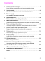
Contents
Overview . . . . . . . . . . . . . . . . . . . . . .
Product Information . . . . . . . . . . . . . . .
Key Printer Locations and Parts. . . . . . . . .
Model and Serial Numbers
. . . . . . . . . . .
Product Specifications
. . . . . . . . . . . . .
Documentation
and Software
. . . . . . . . .
Documentation
. . . . . . . . . . . . . . . . . .
Software
. . . . . . . . . . . . . . . . . . . . .
New Product Features . . . . . . . . . . . . . .
The HP LaserJet 5P/5MP Status Panel
. . . .
The GOand RESET Buttons
. . . . . . . . . .
The Status Lights . . . . . . . . . . . . . . . .
Common LEDpatterns
. . . . . . . . . . . . .
Paper Movement Overview
. . . . . . . . . . .
Infrared Communication
. . . . . . . . . . . .
To Print Using the Infrared Port . . . . . . . .
Troubleshooting IR Printing Problems
. . . . .
Interface Connections
. . . . . . . . . . . . . .
The Parallel Printer Interfaces
. . . . . . . . .
Resource Saving . . . . . . . . . . . . . . . . .
I/O Buffering . . . . . . . . . . . . . . . . . . .
Service Mode, PJLDefaults
. . . . . . . . . .
Test Pages and Resets . . . . . . . . . . . . . .
Printing aSelf-Test Page . . . . . . . . . . . .
Life Expectancy of Consumables
. . . . . . .
Removal andlt.eplacement
. . . . . . . . . . .
Overview . . . . . . ...’....
. ., . . . . .
Required Tools . . . . . . . . . . . . . . . . . .
Removing the Power Door....
. . . . . . . .
Removing the I/O Cover . . . . . . . . . . . . .
Removing the Left Side Cover.
. . . . . . . . .
Removing the Top Cover . . . . . . . . . . . . .
Removing the Tray 1 Pickup Assembly . . . . .
Removing the Formatter Board and Shield
. .
Removing the Fusing Assembly . . . . . . . . .
Removing the DC Controller Assemblies . . . .
Troubleshooting
. . . . . . . . . . . . . . . . .
Continuable Data Error Light Patterns
. . . .
Error 53-- Memory/SIMM Errors . . . . . . . .
Fatal/Service Errors . . . . . . . . . . . . . . .
Infrared Port Not Responding.
. . . . . . . . .
Using the Infrared Test Tool . . . . . . .’. . .
Parts and Diagrams
. . . . . . . . . . . . . . .
Ordering Parts
OrderingConsumables’I;IIIl
IIIIJI:ll:II..69
. . . .
. . . .
. . . .
. . . .
. . . .
. . . .
. . . .
. . . .
. . . .
. . . .
. . . .
. . . .
. . . .
. . . .
. . . .
. . . .
. . . .
. . . .
. . . .
. . . .
. . . .
. . . .
. . . .
. . . .
. . . .
. . . .
. . . .
. . . .
. . . .
. . . .
. . . .
.1.....41
. . . .
. . . .
. . . .
. . . .
. . . .
. . . .
. . . .
. . . .
. . . .
. . . .
. . . .
. . .
. . .
. . .
...5
. . .
. . .
...8
...9
. . .
. . .
. . .
. . .
. . .
. . .
. . .
. . .
. . .
...25
. . .
...27
...28
. . .
...32
. . .
. . .
. . .
...37
...38
. . .
...39
. . .
2
3
4
6
8
10
10
10
11
12
16
18
20
22
26
30
33
36
37
39
40
. . . 44
. . . 47
. . . 50
. . . 51
. . . 55
. . . 56
. . . 58
...60
. . . 65
. . . 66
. . . 68
,.68
.
Ill
Accessories
. . . . . . . . . . . . . . . . . . . . . . . . . . .
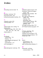
Index . . . . . . . . . . . . . . . . . . . . . . . . . . . . . . .
iv
86
87
.
0’”
●
m..:
i
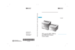
HP LaserJet5P’Printer
ServiceSupplement
HP LaserJet 5P Printer Service Supplement
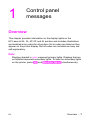
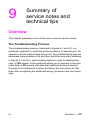
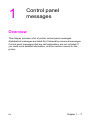
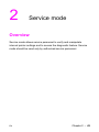
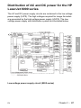
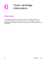
Overview
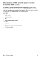
Overview
The HP LaserJet 5P and 5MP pfinters (HP Product Numbers
C3150A and C3155A) have many service and repair processes in
common with their predecessors, the HP LaserJet 4L/4ML and
4P/4MP printers. These processes are documented in the
Combined Service Manual for the HP LaserJet 4L14ML
(C2003A /C2015A) HP LaserJet 4P14MP (C2006A /C2040A). The
purpose of this appendix is to provide supplemental service
information that is unique to the HP LaserJet 5P and 5MP
printers.
2
e
HP LaserJet 5P Printer Service Supplement
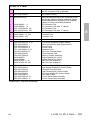
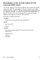
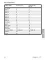
Product Information
●
Product Information
Prinh?r
Features
Features
6 PPM
Print Speed
a
Text & Graphite
~
600 dpi; plus Resolution Enhancement Technology (REt)
Resolution
Printer Lsnguages
HP LaserJet 5P
Enhanced PCL 5
Postscript Level 2’
Enhanced PCL 5
HP LsaerJet 5MP
Monthly Ueage (psgea)
up
Memory:
2MByte on-board standard memoy
Trsy 1 Capacity
100
Trey 2 Cspacity
250
Output Trey capscity
100
Internal Typefaces
HP LaserJet 5P
45 PCL
12,000
45 PCL, 35 PS
LsserJet 5MP
●
to
Standard interfaces
2 Parallel (B connector, C connector)
1 LocalTalk
1 SIR
Power Control
Power switch
NVRAM
Yes
Statua Panel
2 Buttons
5 LEDs
Economode
(toner saving)
yes
Min. Paper Size
(using flat paper path)
‘SIMM includes 1 MByte additional
3 x 5 inch
(76 x 127mm)
,
memory.
0’
3
HP LaserJet 5P Printer Service Supplement
Product Information
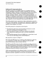
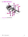
Key Printer Locations
and Parts.
Q
9
Q
9
0
A
Q
Figure 1
1.
2.
3,
4.
Front View
Status Panel
Top Output Tray
Tray 1- Multi Purpose Tray
Tray 2- 250-sheet Paper Cassette
5.
6.
7.
Infrared Port and Status Light
Removable Side Panel
Interface Cable Door
o
e
o
Q
Q
A
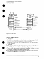
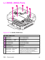
Figure 2
1.
2,
4
Rear View
Top Cover Release Button
Rear Output Tray
3.
4.
5.
Serial Number Label
Power Cable Door
On/Off Button
HP LaserJet 5P Printer Service Supplement
Product Information
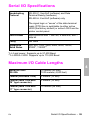
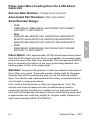
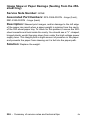
Model and Serial Numbers
The model number and serial numbers are listed on identification
labels located on the rear of the printer. The model number is
alphanumeric, such as C3 150A for the HP LaserJet 5P ~ri nter and
C3 155A for the HP LaserJet 5MP printer.
The serial number contains information about the Country of
Origin, the Revision Level, the Production Code, and production
number of the printer.
The rear labels also contain power rating and regulatory
information as shown in Figure 3.
.,-.. —...
-!,—.’— —
Illltillllllllnlllnlllnlllll
LI 0434A
FCWER Rmltm
W-.O
==~~’&5FZ7Ej
L.
Figure 3
Md 1986
,
%mpk? Mcx-kl and serial Numk)w Labels
5
HP LaserJet 5P Printer Service Supplement
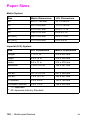
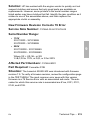
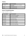
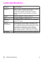
Product Specifications
Product Specifications
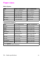
Dimensions
Width
15.79 in. (401 mm)
Depth
17.38 in. (441 .7mm)
Height
7.92 in. (201.1 mm)
Weight
15,4 Ibs. (7 kg)
I
1-
39.5 inches/1
.. . .. .
Figure 4. Location $pace Requirements
6
000 mm
.
..
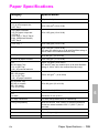
HP LaserJet 5P Printer Service Supplement
Product S~ecifications
Electrical S~ecifications
Power Requirements
100/1 20V (+/- 10%) 50/60Hz (+/- 2Hz)
127 Volts NOM
220/240V (+/- 10%)50
Hz (+/-
I
2Hz)
7iiiiEEE3
Power Consumption (typical for HP
LaserJet 5P and HP LaserJet 5MP)
Minimum recommended
capacity
circuit
Environmental
I
Item
Temperature
(printer and toner cartridge)
I Relative humidity
Duing printing -165 W (average)
Duing printing -165 W (average)
During standby - 5W (instant power
During standby - 5W (instant power
4 Amps
1.8 Amps
I
S~ecifications
Storage/Standby
Operating Printing
I
59”
tO 89°
F (15” to 32.5° C)
-4°
to
104° F (-20”
tO 4(1” C)
I
110%,080%
Ilo%to,o%
I
AC.CSLMC
Emissions (Per 1S0 9:296)
*In this mode, the printer is essentially
quiet.
7
HP LaserJet 5P Printer Service Supplement
Documentation and SoMware
Documentation and Software
Documentation
You can order the documents
some documents.
Table 1.
I
listed below. There is a charge for
Related Documentation
Title
The PCUPJL Technical Reference Package contains the following
documents*
I Part Number
5961-0601
PCL5 Printer Language Technical Reference Manual.
Explains the PCL 5 printer language for experienced users and
programmers.
Printer Job Language Technical Reference Manual.
Explains HP’s Printer Job Language (PJL) for experienced users
and programmers.
PCUPJL Technical Quick Reference Guide.
PCL Comparison Guide.
Describes the different implementation of commands and
extensions across the printer family supporting PJL and PCL 5.
HP LaserJet 5P/5MP Printer User’s Manual
C3150-90901
HP LaserJet 5MP Macintosh Notes* (included with HPLaserJet
5MP Printer and optional Adobe PostScript Level 2 SIMM)
C3155-90901
HP LaserJet Printer Family Paper Specification Guide*
5002-1801
* This item must be ordered through HP Parts Direct Ordering, (800) 2278164. Outside the U. S., see the ordering information in “Parts and Diagrams”
later in this chapter.
8
HP LaserJet 5P Printer Service Supplement
Documentation and Software
Software
The following software driver diskettes are shipped with the
C3150A HP LaserJet 5P printer:
The HP LaserJet 5P DOS Utilities and DOS Printer Drivers
diskette. The DOS utilities include a Status Monitor and
Remote Control Panel. The DOS printer drivers include
WordPerfect (versions 5.1, 5.1+, and 6.0) and Lotus 1-2.3
(versions 2.3,2 .4,3.1 and 3.4).
The HP LaserJet Printing Svstem for Microsoft Windows 3.1
and 3.11 contains the PCfi d“tivers ‘and the HP FontSmart
utility for font management.
The following software driver diskettes are shipped with the
C3155A HP LaserJet 5MP printer:
~ The HP LaserJet 5MP Printer Software for Macintosh.
System 6.07 to 7.5.
SUppOrtS
~ The PostScript Printer Software for Windows 3.1 and 3..11
includes the PostScript drivers and the H-P FontSmart utility
for font management.
HP LaserJet 5P Printer Service Supplement
New Product Features
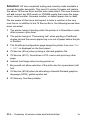
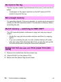
New Product Features
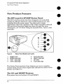
The HP LaserJet 5P/5MP Status Panel
This HP LaserJet printer has been designed to be controlled
mainly by software. However, some simple functions are also
available from the status panel. You also receive status
information about the operation of the IrDA-compatible infrared
(IR) port from the status light just above the port (for more
information, see “To Print Using the Infrared Port,” later in this
appendix).
Figure 5
1.
2.
3.
4,
Status Panel Buttons and Lights
RESET button
ERROR status light
TRAY 1 status light
TRAY 2 status light
5.
6.
7.
8.
DATA status light
READY status light
GO button
IR port status light
The Status Panel consists of two buttons you use to complete
certain tasks and five status lights that indicate the status of the
printer (see Figure 5).
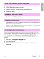
The GO and RESET Buttons
The printer has two buttons: GO and RESET.
10
HP LaserJet 5P Printer Service Supplement
New I’roduct Features
Pressing the GO button
●
●
~ Tells the printer to resume printing.
~ Prints a demo page. The printer must be in Ready Mode (the
green Ready light on steady).
Q Prints a self-test page when pressed simultaneously with the
RESET button. The printer must be in Ready Mode (the green
Ready light on steady).
Pressing the RESET button:
o
Clears
incomplete
0
clears
errors.
print jobs
from the printer’s
memory.
Q Removes all temporary fonts and macros.
Q Returns all printer settings to the default values that you
selected.
The Status Lights
There are five Status Panel lights on the printer:
~ ERROR
@ TRAY 1
Q TRAY 2
~ DATA
~ READY
●
●
These lights indicate the current status of the printer by
displaying an amber or a green hue and flashing individually
sequentially as a group (cascading).
The status light above the IR port indicates tlhe current status of
the IR port by displaying a green hue. This status light comes on
only when the IR port is being used—the Status Panel lights
operate the same for the IR port as they do for any other port on
the printer.
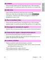
ERROR
●
or
(amber)
Indicates an error condition, such as a paper jam, missing l;oner
cartridge, or the printer’s top cover is open.
11
HP LaserJet 5P Printer Service Supplement
New Product Features
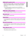
TRAY 1 (amber)
Tray 1 (the MP tray) is empty. Add paper to Tray 1. When the
Tray 1 light is flashing, the printer is waiting for paper to be
manually fed into Tray 1. Once you have inserted the paper, you
must press the GO button to feed the paper.
●
TRAY 2 (amber)
Tray 2 (the Paper Cassette) is empty. Add paper to Tray 2.
●
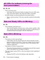
DATA (green)
When the Data light is on, the printer is printing. When the Ready
light and the Data light are both on, the printer still has unprinted
data in its memory. Either press GO to print the remaining data,
or press RESET to clear the data from the printer’s memory.
READY (green)
The printer is in Ready Mode when the Ready light is on. If the
light is flashing, the printer is currently receiving data or in the
process of printing.
IR Port Status Light (green)
If this light is on, it indicates that an infrared (IR) connection
been established.
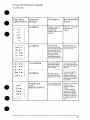
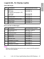
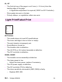
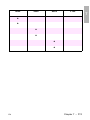
Common LED patterns
The chart following shows the light patterns for normal HP
LaserJet 5P/5MP printer states.
12
has
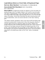
HP LaserJet 5P Printer Service Supplement
New lProduct Features
Light Pattern
$rYD
Qn
Description
The printer is in Ready Mode and is ready to
print. Press the GO button to print a demo
page. Press the GO and RESET buttons to
print a self-test page.
~=
fln
;
u-
~.
Qn
@a
lqm
1
v-
~n
Qn
~m
The printer has received data. If the Fleady
light is flashing, the printer is processing the
data–wait for the next page to be printed. If
the Data light and the Ready light are both on
for an extended period of time (the Ready light
does not begin to flash), press the G(I button
to print the next page. A document or page
may take a long time to print if, for example,
the document or page contains complex text or
graphics.
The printer is warming up or resetting after you
have pressed the RESET button. The lights on
the Status Panel “cascade” (each light turns on
and off sequentially) until the printer is ready to
print.
fl!?a
1
0-
g+.
Q.
BD
Tray 1 (the MP Tray) is empty. Add paper to
the tray. If the Tray 1 light is flashing, the
printer is waiting for paper to be marwally fed
into Tray 1. Once you have inserted the paper,
you must press the GO button to feed the
paper.
an
1
Un
13
HP LaserJet 5P Printer Service Supplement
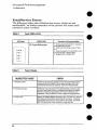
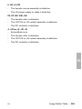
New Product Features
Light Pattern
Description
Tray 2 (the Paper Cassette) is empty. Add
paper to the tray.
$j?=U
~n
Qm
QO
I
on
*.
Qa
A data error has occurred. Press the GO
button to continue printing (some data maybe
lost). For more information, see “Data Error
Light Patterns,” later in this appendix.
~n
Qm
Un
I
*R.
Q-n
~nm
Qnn
A SIMM error has occurred. Make sure your
SIMM is installed correctly. Replace the SIMM
that caused the error. Or press the GO button
on the printer to continue without configuring
the SIMM that caused the error. If the SIMM
has more than one bank of memory, the good
banks will be automatically configured.
000
1
*.
Qn
Qn
Qn
Vn
:
A recoverable error has occurred, such as a
paper jam, the top cover is open, or the toner
cartridge is missing.
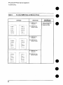
HP LaserJet 5P Printer Service Supplement
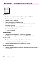
New Product Features
Light Pattern
Description
A fatal error has occurred. Turn the printer off
and then back on, If the same light pattern
reappears, turn the printer off again al~d leave
it off for about 10 minutes, then turn it back on.
If the same light pattern reappears. refer to the
discussion of Fatal Errors in “Troubleshooting.”
:<:~~;<,,
,,,/
@@
El
When the IR port status light is on, a
connection has been established, If you are
printing to the IR port and the status light does
not come on, make sure the printer is in Ready
Mode and that the IF{ port you are printing from
is within range of operation and is kDAcompliant. If you continue to have trouble
printing, refer to the ‘Infrared Port Not
Responding” table, later in this section.
15
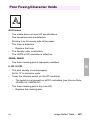
HP LaserJet 5P Printer Service Supplement
New Product Features
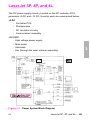
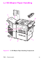
Paper Movement
Overview
The paper feed system picks print media automatically from the
paper cassette or accepts it from the manual feed slot and delivers
it to the image formation system at precisely the right time. The
system then feeds the media to the fusing station, and delivers the
finished product to the output position, either the face-down
output tray on top of the printer, or through the face-up delivery
slot at the rear of the printer. The output path is user-selectable by
opening the rear output tray.
e
●
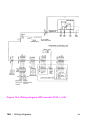
Figure 6 shows the possible paper paths and locations of the
various solenoids, photosensors and rollers.
●
16
HP LaserJet 5P Printer Service Supplement
New Product Features
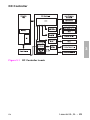
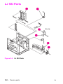
DC Controller
I
Fkwc!
Paper Cassette
6
PCA
___
.
.’
HP LaserJet 5P Printer Paper F%M
Psi
Input Paper Sensor
PS2
Tray 2 Paper Out Sensor
Input Paper !3ensor (PSI) Positions:
A = Manual Feed Sense Pcsition
PS3
Exit Paper Sensor
B = Registration Sense Position
PS4
Winding Paper Sensor
C = TOP Sense Position
PS5
Tray 1 Paper Out Sensor
SLI Tray 2 Solenoid
SL2 Tray 1 Solenoid
17
HP LaserJet 5P Printer Service Supplement
New Product Features
Infkared Communication
The HP LaserJet 5P and 5MP printers are equipped with an
Infrared Datalink Association (IrDA) compliant port. The IrDA
specification allows “wireless” transmission of print data between
a wide variety of hosts (primary) and peripheral (secondary)
devices. A primary device -- such as a PC or laptop computer -- is
capable of reading and writing data to another primary device or
writing to a secondary device, such as a printer. Secondary devices
are read-only; they cannot initiate its own communication, and can
only respond to a host command when properly addressed.
The IrDA protocol uses a transceiver chip in both devices to send
and receive data packets. The packets are checked for validity, and
a response is sent by the secondary device indicating whether the
packets were complete or in error.
The IrDA protocol is contained in three layers:
●
●
●
The physical electronics are the hardware elements in each
device for sending and receiving the data.
The Link Access Protocol (LAP) layer controls the physical
layer, packetizes/unpacketizes
data, and sets transmission
rates.
The Link Mana~ement Protocol (LMP) laver routes data to and
from the host o~erating system (DOSfii~dows).
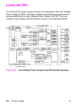
The data flow is shown in Figure 7.
The LAY and LMP layers can reside in either firmware, software,
or a combination of both. There are different LAP and LMP
protocols for primary and secondary devices.
The HP LaserJet 5P printer has the complete secondary protocol,
and any host trying to communicate via the infrared (IR) port must
have the complete primary protocol installed. The prirmwy protocol
software is the responsibility of the host supplier. It is not provided
by Hewlett-Packard Company with the printer.
IrDA communications can be obtained either via an internal IR
port or an external IR accessory. Several manufacturers offer
complete accessory upgrades for both host and peripheral devices.
18
HP LaserJet 5P Printer Service Supplement
New Product Features
Application
ASCII
-%,
. ,
$ffji?y
sec ~e:crg
Data
El Q
GDI
DDI
Windows
System
ASCII to
Raster Data
1/0 Buffer
ASCII
Dot>
Pir DVR
Standard
U Ptinter
IRLMP
IRLMP
IR Redirector
(Software)
UnFack$
IRLAP
IR Driver Packetizes
Data (SW or FW)
IR!AP
Checks
IR Physics
Protocol
De$erla!!zer
IR Chip
IR Physical
Protocol
IR Chip
endows
Driver (SWI
Formatter
Sencwzer
s
Buffer
Data
Packets
d
Transmiitel
Figure 7’, lR Dab Flow.
System Requirements
0 ~ar~ware
. Both the primary and secondary devices must be equipped with
an IrDA-compliant IR component. Older, non-lrDAcompliant devices may not be compatible with the HP LaserJet
5P/MP printers.
~ Software
The primary device must be loaded during boot-up with software
provided by the manufacturer for infrared operation.
. The primary device must be properly configured with an infrared
COM port, IRQ level, and base address value.
● The infrared port must be installed
and selected in the Printers
section of the Windows Control Panel.
●
19
HP LaserJet 5P Printer Service Supplement
New Product Features
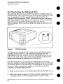
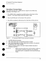
To Print Using the Infrared Port
The infrared (IR) port on your HP LaserJet 5P or 5MP printer is
located on the lower front left corner of the printer (Figure 8). This
port is compliant with the specifications de~ermined by the
infrared Data Association (IrDA). Just above the port is a status
light that indicates when the port is activated. To use the IR port,
you need to use a portable device that also includes an
IrDA-compliant IR port and be within the range of operation (see
Figure 9).
Figure 8
lrDA Port Location
The IR port is compatible with a wide variety of IrDA-cornpliant
portable devices; however, the method for printing will vary
depending on the type of device and the operating system in use.
Refer to the instruction manual for your portable equipment for
specific instructions on printing from that device.
The IR port works by receiving data similarly to a serial port,
however, without a cable and operates at speeds of up to 115 k bits
per second. When the IR connection is established, the status light
comes on. If the connection is broken or when the print j ob is
complete, the status light goes off,
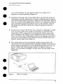
1. Make sure the printer is in Ready Mode (the Ready light is on).
2. Align your laptop computer (or other portable equipment) that
is equipped with an IrDA-compliant IR port within 3 feet
20
HP LaserJet 5P Printer Service Supplement
New I’mduci Features
(1 m) of the IR port on the printer and at an angle of *1 5
degrees to ensure printing (Figure 9).
3.
Send the print job. The status light above the IR port turns on
(printing a complex document or using a software print spooler
on your PC may delay the time it takes for the IR status light to
turn on). If the status light does not turn on, realign the port on
your portable equipment with the port on the printer, resend
the print job and stay within the range of operation during
printing.
4.
If you have to move the device, for example, to add paper, make
sure you stay within the range of operation to maintain the
connection. If the connection is interrupted before your print
job is complete, the IR port status light will turn off. You have
from 3 to 40 seconds (depending on the host implementation)
to
correct the interruption and continue the job. In this case, the
IR port status light turns back on.
5.
The connection can be permanently broken (interruptec[ for
more than 3 to 40 seconds) if the “sendin< IR port is moved out
of the range of operation or if anything passes between the two
ports to b~ock the transmission, such &-a hand or piece of
paper, or even direct sunlight. In this case, the job needs to be
reprinted.
21
HP LaserJet 5P Printer Service Supplement
New Product Features
If you still have problems printing, make sure you are using an
IrDA-compliant device and proper software and have selected the
proper port for printing. See “Infrared Port Not Responding” on
page 65.
Note
The IrDA standard for infrared communications
represents an emerging technology, Older
non-IrDA-compliant
portable devices may not be
compatible with your HP LaserJet 5P/5MP
printer. If you continue to have problems
printing using the IR port, contact the
manufacturer or dealer where you purchased
your portable device to verifj compatibility with
the IrDA standard, and follow the
troubleshooting procedure immediately
following.
Troubleshooting
IR Printing Problems
IR printing problems maybe caused by any of the several system
components or by lack of proper conf@u-ation.
The following
checklist will help determine the source of the problem.
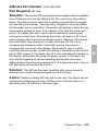
6. Verify the user is operating the printer and PC as described in
the User’s Manual: less than one meter between devices, and
not more than *15 degrees from direct center.
7. Verify the host PC or laptop and the printer are IrDA-compliant
and have the necessary hardware components for IR
communication.
8. Verify the IR software has been loaded on the primary device.
(This is system software and should be available from the PC
manufacturer. )
9. Verify the host PC or laptop is properly configured. Check the
port assignment, the IRQ level, and the base address value.
Check both the DOS AUTOEXEC.BAT
and CONFIG.SYS files,
and the Windows system configuration.
22
HP LaserJet 5P Printer Service Supplement
New Product Features
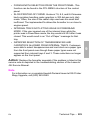
If all these elements are properly installed and configured, use the
IR test tool to test the IrDA protocol transmission and device
operation. This tool for troubleshooting IR communication
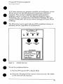
problems, shown in Figure 10, has been developed by Genoa
Technology, Inc., in cooperation with Hewlett-Packard.
The part
number is 5062-4661 and can be ordered through HP Parts Direct
Ordering.
The IR test tool can be used with any IrDA-compliant
secondary device, regardless of manufacturer.
1
(R Diodes
Test
primary or
I
cOtItIeCt
P&3SS
‘&ooo
● 0
Per+:&l
Computer
Test
Test Modes
PCL Printer
PostScript
Energy
Test
Figure :10
Wrarc!xi
Printer
Detect
Frame
Tt?st ‘TCml
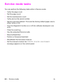
To test the peripheral
device:
1. Put the HP LaserJet 5P in Ready Mode.
2. Press the “Peripheral Test” button on the test tool. The LEDs
on the test tool will sequence.
23
HP LaserJet 5P Printer Service Supplement
New Product Features
If the “PASS” LED lights, the test was successful, indicating that
communication with the printer’s IR port is functioning nor&ally.
On HP LaserJet printers, a self-test page will be initiated by the
test.
●
If the “TEST’ LED goes out and the “PASS” LED fails to light, the
printer’s IR port is not functioning correctl~ check the operator’s
instructions included with the IR test tool.
@
To test the host computer
1. Place the test tool on a table in front of the PC’s IR port
2.
Press the “Computer
the LEDs.
Test” button. The test tool will sequence
If the “PASS” LED light, the test was successful, indicating that
communication with the printer’s IR port is functioning normally,
If the “TEST’ LED goes out and the “PASS” LED fails to light, the
host’s IR port is not functioning correctly.
●
24
HP LaserJet 5P Printer Service Supplement
New Product Features
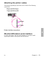
Interface Connections
●
●
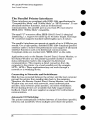
Your HP LaserJet 5P or 5MP printer supports the following
interfaces (see Figure 11):
@ ho IEEE.128&omp]iant
parallel ports at the back of the
printer—one large B-type and one small C-type.
@ One LocalTalk
port at the back of the printer.
o One IrDA-compliant
~jg~~[;~j
~p
~~~gi~J~~
infrared
~p/~~~p
port
~~i[~~~f
at
the front of the prirlter.
~~@ff~f-~
~~~~~~~~~n~
1.
LocalTalk cable and connectors,
2.
IEEE-1284 parallel cable and large (B-type) printer connector.
●
3.
IEEE-1284 parallel cable and small (C-type) printer connector. (The cable will
be stamped as IEEE-I 284 compatible.
4.
Host PC connector (A-type) (in the future C-type connectors may also be
available on host PCs).
●
eaufrc)n
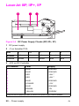
Make sure that all power and interface cables on
your printer and host computer are properly
grounded and in compliance with local electrical
codes.
25
HP LaserJet 5P Printer Service Supplement
New Product Features
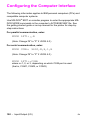
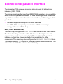
The Parallel Printer Interfaces
These interfaces are compliant with IEEE-1284 specifications for
“Compatibility Mode” and “Nibble Mode” or “HP Bi-tronics”. To use
advanced interface functions, such as hi-directional
communication, the parallel port on your host PC must also be
IEEE-1284 “Nibble Mode” compatible.
●
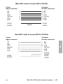
The small “C” connector offers IEEE-1284 II (level 2) electrical
interfacing, i.e. support for cables up to 10 meter length. The large
“B” connector supports standard cable lengths up to 3 meters.
a
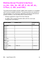
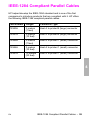
The parallel interfaces can operate at speeds of up to 2 MBytes per
second. Use a high-quality, shielded IEEE-1284 compliant parallel
interface cable to insure best performance and support of advanced
interface functions such as hi-directional communication.
Compliant cables are marked with “IEEE-1284” on the cable.
Applications such as the Remote Control Panel, Status Monitor, or
the Status Window use the printer’s parallel interface to send
status information back to the computer (hi-directional
communication). This requires a direct connection from the
computer to the printer via a local parallel port (for example,
LPT1:, LPT2:). These applications may not work through a
network or a switching device.
Connecting
to Networks
and Switchboxes
Most devices connected between the printer and the host computer
prevent the printer from sending data back to the computer.
Therefore, the Remote Control Panel, Status Monitor, and Status
Window may not work with networks, most hardware print
spoolers, some software print spoolers, and some switchboxes.
Newer sharing devices are available that fully support status
feedback. Check with your supplier on support for hi-directional
communication.
Automatic
●
I/O Switching
The printer automatically switches between all interfaces (parallel,
infrared, and LocalTalk) when multiple users share the printer.
a
●
26
HP LaserJet 5P Printer Service Supplement
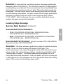
New Product Features
Resource
Saving
Resource Saving gives the printer the ability to save certain
entities such as permanent soft fonts, macros, symbol sets and
user-defined graphics patterns when the printer changes
personalities, resolutions or page protect modes. For example, if a
user switches the printer from PCL mode to PostScript mode, all
PCL soft fonts and macros are lost.
With resource saving, the HP LaserJet 5P/5MlP printer can retain
these in memory. When the user switches back to PCL from
PostScript all of the PCL entities would still be resident in the HP
LaserJet 5P/5MP printer. Resource Saving can be changed via
software, but can only be accessed when the printer has the
PostScript language installed and a minimum memory
configuration of 7 MB.
Resource Saving can be set via software for one of three mocles,
AUTO (default), ON, and OFF. Auto configuration sets the
Resource Saving for PCL and Postscript to a minimum value (400
KBytes) for each personality. Setting Resource Saving to ON
allows the user to determine how much printer memory will be
used for Resource Saving for the PCL personality and the
Postscript personality. The memory can be allocated in 100 KBytes
increments. For example, if the user sets the Resource Saving
memory size to 200 KBytes, a total of 400 KBytes of memory will
be assigned to Resource Saving. 200 KBytes of memory will be
used for Postscript Resource Saving and 200 KBytes of mern.ory
will be used for PCL Resource Saving. Turning Resource Sating
OFF disables the Resource Saving fbnction and no memory is
allocated to Resource Saving.
27
HP LaserJet 5P Printer Service Supplement
New Product Features
I/O Buffering
I/O buffering allows the user to allocate printer memory to hold
the job while it prints, freeing up the host system sooner, like a
print spooler. The standard printer has approximately 10 KBytes
of memory allocated to I/O buffering and an additional 100 IIBytes
of memory is assigned to I/O buffering for each MBytes of memory
added to the printer.
If the printer has a minimum of 6 MBytes of memory installed, the
I/O buffer size can also be adjusted via software. Three settings
exist for the 170 buffer; AUTO (default), ON, and OFF. AUTO sets
the printer’s 1/0 buffer to a minimum value that is determined by
the total amount of memory that is resident in the printer. Setting
I/O buffering to ON allows the user to set the 1/0 buffer size
Setting the I/O buffering to OFF disables )70 buffering.
Note
28
When you change the I/O buffer setting all
downloaded resources are deleted.
●
●
HP LaserJet 5P Printer Service Supplement
New Product Features
THIS PAGE INTENTIONALLY
LEFT BLANK
●
29
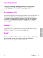
HP LaserJet 5P Printer Service Supplement
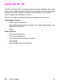
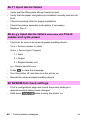
Service Mode, PJL Defaults
Service Mode, PJL Defaults
The Service Mode should be used only by authorized
personnel. While in Service Mode, you can:
service
●
Print a Service Mode Self Test.
●
Verify and set the Page Count (the page count also is displayed
on the standard self test).
●
Set the Cold Reset Default. (This sets the factory default paper
size to either Letter or A4).
●
Set the Demo Page=True/False.
Used to remove the Demo Page
option from the self test menu.
Set the Diagnostic Functions ON or OFF (for software
developers ;se only).
●
●
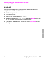
Since the HP LaserJet 5P/5MP printer does not have a front
control panel, Service Mode and many configuration tasks are
accessible only through software (PJL commands).
The following example shows how to use PJL commands to enter
Service Mode and perform various Service Mode configuration
tasks.
Note
Text is CASE-sensitive in PJL; enter exactly as
shown. The EC symbol stands for the ASCII
escape character (ESC or /027). When the PJL
code is entered, print the data file (or use the
DOS COPY command to copy it to the printer).
Detailed explanations of PJL commands and their functions can be
found in the Printer Job Larwuage Technical Reference Manual
(HP part number 5961-0704~
-
30
●
HP LaserJet 5P Printer Service Supplement
Service Mode, PJL Defaults
CkwmK9n PJL commands
~=xp’anation
Mode
@PJL SET SERVICEMODE=HPBOISEID
Enter Service
@PJL SET PAGES=O
Set page count [= xxxxx]
@PJL SET CRPAPER=LETTER
Sets cold reset page size [= Letter/A4]
@PJL SET SKIPDEMO=FALSE
Skips demo/PCL type page [= true/false]
@PJL SET DIAGNOSTICS=OFF
Sets diagnostics [= OFF/ON] (fol’ ISV use)
@PJL SET SERVICEMODE=EXIT
Exits Service Mode
@PJL DEFAULT PAPER= LETTER
Selects user paper size default
@PJL RESET
Performs PJL reset
Ec%-1 2345X
Exits PJL mode
ECZ
Prints Self-Test page
ECE
Resets the printer.
Other PJL Command examples:
@PJL INITIALIZE
Sets user environment to factory defaults.
@PJL SET ECONOMODE=ON
Sets Economode
@PJL SET PAGEPROTECT=LEGAL
Sets the memory size for page protection
to LEGAL paper size.
@PJL SET MANUALFEED=ON
Sets manual feed mode.
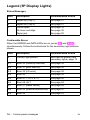
@PJL SET LANG=
Sets the default display languagel
FRENCH,
1 Do not confuse this command with @PJL ENTER LANGUAGE,
the printer language to PCL or PostScript.
which sets
31
HP LaserJet 5P Printer Service Supplement
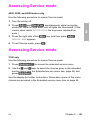
Service Mode, PJL Defaults
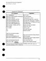
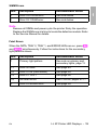
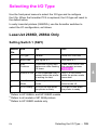
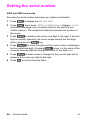
Test Pages and Resets
Test pages, resets, and NVRAM initialization can all be performed
by using the GO and RESET buttons on the HP LaserJet 5P/5MP
printer status panel. Table 2 shows how to perform these tests and
diagnostic functions.
Table 2.
FUNCTION
Button Functions
ACTION
I
RESULT
Self Test
Press GO and RESET buttons
simultaneously.
Prints a Self Test page.
Continuous
Self Test
Hold GO button more than 20
seconds after powering on
pinter
Prints continuous self test
pages. Press the button to stop
printing.
Reset (all 1/0)
Press RESET button.
Clears ail data from memory,
including unprinted data,
downloaded fonts and macros.
rF
Continue
Cold Reset
I
Allows the printer to recover and
(Waiting for paper, or
continuable error.) Press the GO continue printing the job.
Press the GO button,
Hold RESET button less than 20 Clears all data from memory,
seconds after turning power on. including unprinted data,
downloaded fonts and macros.
Resets printer to factory default
NVRAM
Initialization
Hold RESET button more than
20 seconds after turning power
on.
Service Error
Codes
Press GO and RESET buttons
to display additional code.
32
lPrint remaining data imprinter
Clears all 1/0 and print
configuration information from
NVRAM.
See “Troubleshooting” to
determine the problem and
I solution.
HP LaserJet 5P Printer Service Supplement
Service Mode, PJL Defaults
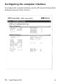
Printing a Self-Test Page
You can print a self-test page to get information about your
printe~s current settings, options, and print quality. You can use
this page to troubleshoot print quality problems and to view
current print density and Resolution Enhancement settings so you
can adjust them.
You can also print the demo, or demonstration,
check that the printer is operational.
page to quickly
To print a self-test page:
Simultaneously press the GO and RESET buttons on the printer’s
Status Panel while the printer is in Ready Mod[e.
Or using the HP LaserJet PCL Windows Printer Driver, unc[er
“Device Option”, select the “Configure Printer” button and choose
“PCL Self-Test Page”.
Or using the Remote Control Panel (in DOS], under “Options”
select “Print Test Page” and choose “PCL Self-Test Page”.
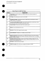
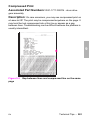
Figure 12 shows a sample self-test page. Numbers in the sample
self-test page match numbers in the Key to Figure 12, which
follows the illustration. The appearance of the self-test page vanes
depending on the options currently installed in your printer.
Note
The factory default for the self-test page is
English. A PJL command is required to change
the self-test language to appear in a language
other than English. Refer to the discussion of
PJL commands on page 31
33
HP LaserJet 5P Printer Service Supplement
Service Mode, PJL Defaults
Gb[
T!%
I ‘“-----”
Figure 12. HP LaserJet 5P Self-Test Page
34
HP LaserJet 5P Printer Service Supplement
Servir;e Mode, PJL Defaults
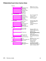
Keyto Figure12. self-l-w
Item I
Page
Explanation
1
Printer Options: Ustspfinter options youcanadjust
“Software Procedures”).
using yourptinter soMare(see
Appenclix F,
2
Test Pages: Shows testpages youcanptint
3
PCLMemory information:
available memory for PGL
4
LocalTalk Name/Node ID/Network Number: lfyourptinter isconnected toa LocalTalk nefwork, shows
the network name, node ID for your ptinter, and the network number.
fromyourprinter,
Shows thetotal amount ofinstalled memoW. Alsoindcates
theamountof
applications.
1
5
Formatter Number:
6
RAMsize:
7
Page Count:
8
Ffrmware Datecode:
Shows setialnumber
ofinternal e[ectronlcsboard,
Shows total installed printer memory,
Shows number ofpagesthe
printer hasprinted.
Eight-dgit date (YYYYMMDD) of formatter fimjware.
Resolution Enhancementi When resolution issetto 600dpi, the Rf?solution Enhancement t,?chnology
(REt) block appears here. The REt block illustrates current resolution enhancement (see “Hne-Tuning Print
Quaky,” in Chapter 2, “Printing”).
+-
l/O Buffering and Resource Saving: information about thecurrent configuration appears here.lfthe
ptinter does not have enough memory installed to enable l/O Buffeting or Resource Saving, the amount of
addtional memory needed appears here,
11
Print Pattern:
Illustrates print density andquality
12
Insfailed Peraonafities:
Shows which printer languages (personalities) are installed.
35
HP LaserJet 5P Printer Service Supplement
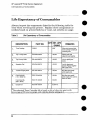
Life Expectancy of Consumables
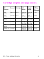
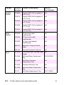
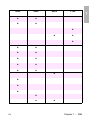
Life Expectancy of Consumables
Always inspect the components listed in the following table for
wear when servicing the printer. Replace these components as
needed, based on printer failures or wear, not strictly on usage.
Table 3.
Life Expectancy of Consumables
PART NO.
DESCRIPTION
QTY EST. LIFE
(pages)
REMARKS
1.
Toner Cartridge
C3903A
1
40001
When print becomes faint,
shake cartridge to diatributa
remaining toner.
2.
Tray 1 Pickup Roller
RG5-2205-OOOCN
1
100,000
Replace roller and
separation pad together.
s.
Tray 2 Pickup Roller
RBI-6332-OOOCN
1
100,000
Look for glazing end
cracks.
4.,
swara~onPad
RF5.0343-OOOCN
1
100,000
Look for glazing and
groovas. Replace together
with Pickup Roller.
s.
Transfer Charging Roller
RF5-I 287-OOOCN
1
100,000
May affecl print quality
and/or paper jams
6.
Fuser Assembly
(115 V, 50/60 Hz)
RG5-I 700-OOOCN
1
100,000
May affect print quality
and/or paper jams. Look for
marks on rollers.
Fuser Assembly
(220 V, 50 Hz)
RG5-1701-OOOCN
1
100,000
Exhaust Fan
RG5-I
1
25,000 hrs.
7-
801-OOOCN
‘The estimated Toner Cartridge life is based on A4 or letter eize prints with
an average of 570 toner coverage, and with the density setting at 3.
36
HP LaserJet 5P Printer Service Supplement
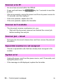
Removal and Replacement
Removal and Replacement
Overview
The removal and replacement procedures for many HP LaserJet
5P printer Field Replaceable Units (FRUS) are identical to the HP
LaserJet 4L and 4P printers. This section describes only those
differences unique to the HP LaserJet 5P for removing:
Power Door
1/0 Cover
Left Side Cover
Top Cover
Tray 1 Pickup Assembly
Formatter Board Assembly
Fuser Assembly
DC Controller Assembly
WARNING!
Unplug the power cord from the power outlet
before attempting to service the printer. If this
warning is not followed, severe injury may result.
Never operate or service the printer with the
protective cover removed from the
Laser/Scanner Assembly. The reflected beam,
although invisible, can darnage your eyes.
CAUTION
The printer contains parts that are electrostatic
discharge (ESD) sensitive. Always service
printers at an ESD protected workstation.
To install a self-tapping screw, first turn it
counter-clockwise
to align it with the existing
thread pattern, then carefully turn clockwise to
tighten. Do not over-tighten. If a self-tapping
screw-hole becomes stripped, repair of the
screw-hole or replacement of the affected
assembly is required.
37
HP LaserJet 5P Printer Service Supplement
Removal and Replacement
Note
Always remove the toner cartridge and the
paper cassette from the printer before removing
or replacing printer parts.
●
Required Tools
Refer to page 6-3 of the Combined
A TORX T-10 head screwdriver
shield.
Service Manual.
@
is needed to remove the formatter
o
38
HP LaserJet 5P Printer Service Supplement
Removal and Replacement
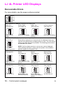
Removing
the Power Door
The Power Door is located on the right rear of the printer.
1. Ensure the power to the printer is turned OFF.
2. Grasp the power door by the finger slot directly above the
power cord, and swing the rear of the door out and forward.
The door easily tilts and lifts out.
3. Unplug the power cord from the printer power socket.
Removing
the 1/0 Cover
The 170 Cover is located to the left rear of the printer.
1. Locate the two release tabs shown in Figure 13.
Press the tabs
39
HP LaserJet 5P Printer Service Supplement
Removal and Replacement
Removing
the Left Side Cover
1. Disconnect
all I/O cables.
2.
Press the Top Cover Release button on the right side of the
printer, and open the top cover.
3.
Press the removable
Figure 14.
4.
Slide the cover forward and pull straight away from the side of
40
side panel release latch shown in
HP LaserJet 5P Printer Service Supplement
Removal and Replacement
Removing
the Top Cover
1. Remove the toner cartridge and paper cassette if they have not
:.-.:>
~,:
/
Figure 15
Removing the Top Cover Screws
3. Grasp the lower left front corner of the top cover, and lift it
forward and up.
4. Grasp the lower portion of the right front cover, and pull
forward and up.
5. At the rear of the printer, lower the face-up output tray.
—
41
HP LaserJet 5P Printer Service Supplement
Removal and Replacement
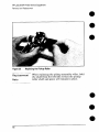
6. Lift the rear of the printer slightly. Grasp the lower right back
corner. With your thumbs, flex the plastic toward you, up, and
out. Figure 16 shows this process for the rear right corner.
Repeat the process for the left rear corner.
—
Note
Note the position of the tabs and the catches
carefully. This step may require considerable
twisting and flexing of the plastic in order to free
the release tabs.
●
●
—
Figure 16
Releasing the Back Corner of the Top Cover.
●
7. Lift the printer cover straight up.
●
42
HP LaserJet 5P Printer Service Supplement
Removal and Replacement
When reseating the top cover onto the p:rinter
frame, ensure the black paper-out flag in front
of Tray 1 is seated in the groove of the Tray 1 lift
plate. If not in the groove, it can easily break
when the cover is forced into place. Refer to
Figure 17
43
HP LaserJet 5P Printer Service Supplement
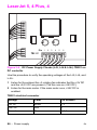
Removal and Replacement
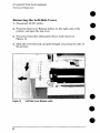
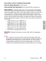
Removing
the Tray 1 Pickup Assembly
1. Remove Tray 1 by opening the tray at a 45° angle and pulling
up on the tray (Figure 18).
Figure 18
Removing Tray 1.
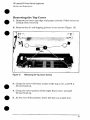
2.
Urmhw the two cables (Callout 2 in Fi~re 19) by grasping the
cables ‘where they attach to the plug a-ridpulling straight back.
3.
Route the cables through the right side of the printer chassis
and bring them to the front.
4.
Remove the 5 screws (callout 1 in Figure 19) from the front of
the pickup assembly. (TWO screws are adjacent in the lower left
corner.)
44
HP LaserJet 5P Printer Service Supplement
Removal and Redacement
Figure 19
Tray 1 Pickup Assembly
Locations,
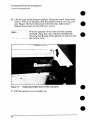
!5. Press the two release tabs on either side o:f the pickup assembly
(callout 3 in Figure 19) and pull the assembly away from the
view.
printer. (The left side release tab is partially hidden hom
Pressing in on both sides will release the tabs.)
6. Pull the pickup assembly straight out from the back of the
printer.
7. To remove the roller from the pickup assembly, grasp the tabs
on the right end of the roller and slide it to th~ ‘~ght’(shown
Figure 20).
in
45
HP LaserJet 5P Printer Service Supplement
Removal and Replacement
Figure
20
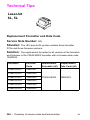
Replacement
Note
46
Replacing the Pickup Roller
When replacing the pickup assembly roller, hold
the shaft from the left side so that the pickup
roller shaft and gears will remain in place.
HP LaserJet 5P Printer Service Supplement
Removal and Replacement
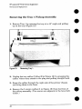
Removing
●
the Formatter Board and Shield
1. Remove any installed SIMMS.
Nott?
a
There are two TORX screws holding the 1/0
connector in ~osition (Callout 1 in Figure 21).
These are th~ only two TORX screws-in the HP
LaserJet 5P printer. Note also the location of
the test print button hole (Callout 2) on the side
of the formatter board cover.
.—
Figure 21
TORX Screw Locations.
47
HP LaserJet 5P Printer Service Supplement
Removal and Replacement
Figure 22
Removing the formatter screws.
2. Remove the (7) screws shown in Figure 22.
3. Pull the formatter board straight from the side of the chassis.
(There will be a slight resistance
interconnect. )
from the DC Controller
4. Pull the DC controller interconnect
out (Figure 23).
5. To separate the formatter PCA from its shield, remove the two
screws (refer to callout 1 in Figure 21).
48
HP LaserJet 5P Printer Service Supplement
Removal and Replacement
Figure 23
NO16?
Removing Me DC Contrcdler Interconnect.
RETAIN THE DC CONTROLLER
INTERCONNECT
when replacing the DC
Controller Board. The replacement board part
number does not include this interconnect.
49
HP LaserJet 5P Printer Service Supplement
Removal and Replacement
Removing
the Fusing Assembly
1. Remove the top cover assemblies.
2. Locate the black plastic fuser cover at the back of the printer.
Press the release tab (callout 1 in Figure 24).
3. Slide the cover all the way to the right.
4. Pull the left end of the strip toward you at a 45° angle.
5. Slide the cover to the left and out of the printer.
6. Remove the four screws (2 self-tapping
screws, two machine
screws with washers) directly below the fuser assembly.
7. Grasp the fuser by the green plastic handle and pull out from
the printer.
‘Figure 24
50
Removing the fuser cover.
a
HP LaserJet 5P Printer Service Supplement
Removal and Replacement
Removing
the DC Controller Assemblies
The DC Controller Assembly is located on the bottom of th e
printer. The PCA is protected by a metal shield assembly, and is
mounted to a plastic base. The Formatter PCA and Fusin,g
Assemblies are connected directly into the DC Controller and must
be removed prior to removal of the DC Controller Assembl y.
Cauiiai’1
Failure to remove these components befme
removing the DC Controller will result in
printer ~amage.
1. Remove the printer covers (page 39), Formatter
(page 48), and Fusing Assemblies (page 50).
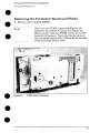
2.
PCA and Shield
On the right side, remove the machine screw and washer
(Figure 25) holding the grounding spring in place. (Callout 1 in
Figure 25).
3. Disconnect the two cables to the tray 1 assembly (callout 2 in
Figure 25).
●
51
HP LaserJet 5P Printer Service Supplement
Removal and Replacement
,
I
Figure 25
4.
Grounding Spring screw location.
On the left side, remove the (2) screws that attach the
grounding strap to the Gear Train Assembly (see callout 1 in
Figure 6-36 of the Combined Service Manual). Turn the
assembly upside-down before proceeding with further steps.
5. Remove the (5) self-tapping screws and the (1) machine screw
with star washer from the bottom of the DC Controller
Assembly. (See callouts 2 and 3 in Figure 6-36 in the Combined
Service Manual.)
6. Lift the DC Controller Assembly
52
away from the printer frame.
HP LaserJet 5P Printer Service Supplement
Removal and Replacement
The PS1 Input Sensor Arm may come loose and
fall out when you remove the DC Controller
Assembly. See Figure 6-51 in the Combined
Service Manual for re-installation.
7. Remove the metal backing plate from the DC Controller
Assembly (see pages 6-43-and 6-44 in the Combined
Manual for this procedure.)
Service
8. Disconnect Tray 1 Interconnect
PCA (callout 2 in Figure 26)
and cable 302 (callout 1 in Fimwe 26) from the DC Controller
PCA.
Remove the Tray 1 Interconnect PCA carefully;
it can easily be broken when separating it from
the black plastic cover.
Note
The Tray 1 Interconnect PCA and cable must
also be retained when replacing the DC
Controller Board. The part number for the DC
Controller Board does not include a replacement
PCA and cable. This cable can be directly pulled
from the connector no releases are necessary.
53
HP LaserJet 5P Printer Service Supplement
Removal and Replacement
Figure 26
Tray 1 Interconnect
PCA and Cable 302
a
a
54
HP LaserJet 5P Printer Service Supplement
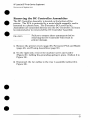
Troubleshooting
●
Troubleshooting
The troubleshooting process for the HP LaserJet 5P/5MP printer
has two key differences from the 4L/4ML prinker:
~ Different error light patterns (5 LEDs instead of 4).
a
@ Infrared port troubleshooting.
This section provides a list and explanation of the error LED
patterns and instructions on troubleshooting the infrared port
●
55
HP LaserJet 5P Printer Service Supplement
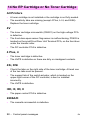
Troubleshooting
‘e
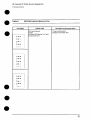
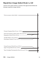
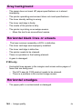
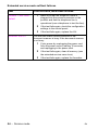
Continuable
Data Error Light Patterns
Possible data error light patterns are listed in the first column of
the following table. If the Error and Data lights on the Status
Panel are lit, simultaneously press the GO and RESET buttons on
the printer to display a secondary light pattern. This secondary
light pattern, or data error light pattern, will more precisely
describe the problem. Where more than one data error light
pattern is possible, corresponding computer messages are listed in
the second column.
Data Error
Light Pattern
*.
Computer
Message
Description
Recommended
Action
20 MEM
OVERFLOW
Too much data, or date
too complex.
Turn Page Protedion ON
or to AUTO (can be set
within the Remote Control
Panel),
2. Add optional memory.
3. Reduce the complexity
of the print job,
Da
DO
Qn
Press (20
ptinting,
00
n
*U
to resume
PRINT
OVERRUN
21
ljlm
Da
@D
on
n
22 IO ERROR
~n
Qn
QQn
on
2
56
The computer and printer
are not communicating
because of improper
signal protocols. Indicates
a loose cable connection
or a bad or poor quahy
cable.
Reseat the cable and
make cure you are using
a high-quality cable
HP LaserJet 5P Printer Service Supplement
Troubleshooting
)ata Error
ight Pattern
Computer
Message
Description
Recoin:
Action
40 ERROR
Indicates an abnormal
con nection break
occurred while
transferring data from the
computer.
Press GQ
to clear the:
message,
A temporary error
occurred while ptinting.
This error most commonly
occurs when the pfinter
picks two sheets of paper
at once. The page
containing the error is
reprinted automatically.
(first two light sequences)
Remove the
the output tr
GO on the I
(flrsl and second Ight
sequence)The pfinter
detected a temporary
error condition.
Turn the pfir
on, If the pro
replace the I
assembly.
*U
~m
Da
Qm
vu
3
41
ERROR
@mDa
~..
n
Bum.
Quo.
Wnan
1
51/52
&m-m
ERROR
Qnmm
Qnma
Qm.
m
55 ERROR
Vmnn
1
*.D
68 SERVICE
or 68
~nm
READY/SERVICE
~mm
Qmm
C)mu
I
(third light sequence)
The printer detected a
temporary error condition
The pflnter’s nonvolatile
memory (NVRAM) is full.
Turn the prin
back on, If pi
persists, repl
Controller. If
still continue
formatter PC
Press GO
to clear thee
message.If i
persists,
1, Perform I
Reset to clee
(hold down tt
button for mc
seconds duti
2. Replace II
PCA.
57
HP LaserJet 5P Printer Service Supplement
Troubleshooting
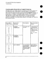
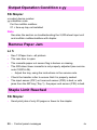
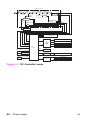
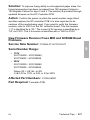
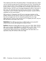
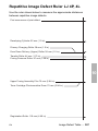
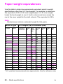
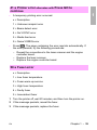
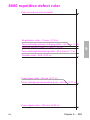
Error 53-- Memory/SIMM
Errors
Error 53 is indicated by a combination of the Error LED and either
Tray LED, on and steady. More detail about the error is found by
pressing the GO and RESET buttons simultaneously, which causes
a secondary sequence of light patterns. These secondary patterns
form a binary representation of the exact hardware type, device
and error number in the form 53-XY-ZZ as shown in Table 4.
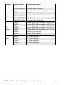
Table 4.
X-Hardware
Type
●
●
Memory Error Codes
Y-Hardware Device
22. Error Number
O: ROM
O: On board RAM/ROM
00: Unsupported
memory
1: RAM
1: SIMM slot 1
01: Unrecognized
2: SIMM slot 2
03: Unsupported
3: SIMM slot 3
04: Invalid SIMM speed
memory
memory size
05: SIMM reporting information
incorrectly
06: SIMM address conflict
07: SIMM address conflict
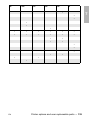
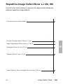
Figure 27 explains how to read the light sequences. The initial
sequence (Part 1) shows that ERROR 53 can be indicated by two
different light sequences, depending on the X value: ROM (x =0) or
in RAM (x =1) . Pressing GO and RESET together produces a
secondary light pattern, which reveals the Y- and ZZ- values,
which complete the error code (Part II) . The binary Y value is read
from the top two LEDS; the binary Z value is read from the lower
three LEDS. Part III of Figure 27 shows the binary values of the
different light combinations.
58
●
e
HP LaserJet 5P Printer Service Supplement
l-roubleshooting
Figure
-27
%c,ondary
Light Patterns
59
HP LaserJet 5P Printer Service Supplement
Troubleshooting
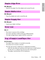
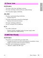
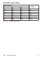
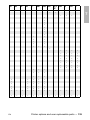
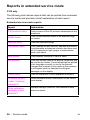
Fatal/Service
Errors
The following tables show fatal/service errors, which are not
continuable; no further operation of the printer will occur until
corrective action is taken.
Fuser Malfunction
Table 5.
LED
ERROR CODE
DiSfiSy
Fuser Malfunction
Table 6.
I
I
Description
end Recommendation
1. Remove power to the printer for 10 minutes.
If this doesn’t clear the error
2. Perform the Fuser Checks shown in Table
C-6.
3. Check the Fuses (FIJI 01 and FU20i ) on the
DC Controller PCA. Replacx if fauity,
3. Replace the DC Controller PCA.
Fuser Checks
SUSPECTED CAUSE
1. Connector Contact
Ensure that JI03 and J204 connectors on the Fusing Assembly are seated
securely into the OC Controller PCA connectors (see Figure 6-29 in the
~Combined Service Manual for locations). Reseat the Fusing Assembly.
2. Thermistor wire open,
Remove the Fuser and measure the resistance between connectors J204-1
and J204-2 (see Figure 6-29 in the Combined Service Manual for location).
Resistance should read approximately 440 K Ohms at 20 Deg C (room
temperature). If the thermistor wire is open, replace the Fusing Assembly.
L
60
Measure the continuity between connectors JI 03-1 and JI03-2 on the Fuser
(see Figure 6-29, the Combined Sewice Manual for location). It should be
approximately 30+5 Ohms for 100-120 VAC or 127+5 Ohms for 220-245
VAC. Ii the thermal fuse is open, replace the Fusing Assembly.
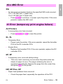
HP LaserJet 5P Printer Service Supplement
Troubleshooting
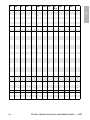
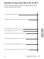
-i-able 7.
57/5!3 Main MoW Failure
LED
DiSflby
ERROR CODE
57/58 Main Motor Failure
~..
~mm
@-n
Q-n
Oon
1
&.n
~mn
~mm
(J-m
Uan
1
Dsscriplion
and Recommendation
The DC Controller haa reported a
general motor failure. Ttle Main Motor
is controlled by the DC Controller
PCA, and seated into co mector J601.
Power-cycle the printer. If this doesn’t
clear the message:
1. Does the main motor rotate on
power-up? If no:
a. Reseat the Main Motor into the DC
Controller connector.
b. Inspect the Gear Trair for debrk
thet would block the free operation of
the gears.
c. The toner carttidge m:ly not be
rotating. Refer to “Drum Rotation
Fundional Check in the Combined
SeNice Manual.
d. Main Motor faulty. Pcwer up the
printer and observe if stacker rollers
rotate. If not, replace the Main Motor.
e. Replace the OC ContrNer PCA.
If the main motor does rotate:
2. Does the fan turn duting ptinting?
If no:
a. Power-cycle the ptintc,r.
b. Check the fan to dete ‘mine if it is
Iblocked from operation.
c. Reseat the fan connector on the
laser/Scanner Assembly.
d. Replace the Fan.
e. Replace the Laser/Se wrner
Assembly.
f, Replace the DC Controller.
!J Replacethe connector between the
scanner and DC Control lh?r.
61
HP LaserJet 5P Printer Service Supplement
Troubleshooting
Table 8.
61.x/62,x SIMM Parity and Memory Errors
LED Display
ERROR CODE
61.1 SIMM Slot One
Parity Error
$.0
g+.
Q-n
Q-w
.
62.1 SIMM Slot One
Memoiy Problem
Q-m
Qmn
fJm
-
Qmn
00
D
Uo
D
ID
61.2 SIMM Slot TWO
Parity Error
~.
+-.
~mm
Q-m
@-n
Qma
~mn
Q-m
Vcla
Una
D
62.2 SIMM Slot TWO
Memory Problem
In
61.3 SIMM Slot Three
Parity Error
$,.
Xl
62
.
62.3 SIMM Slot Three
Memory Problem
+.U
Qmn
~.n
Q-m
Q-w
Qmn
Qm
Vna
Vna
-
Description and
Recommendation
1. Power-cycle the printer.
2. Reseat the SIMM.
3. Replace the SIMM,
HP LaserJet 5P Printer Service Supplement
l“roublesllooting
Table 9=
LED ~SplSy
62/63/64Internal Memory Error
ERROR CODE
2.0 Internal Memory
‘roblem
3 Internal RAM Memory Test Failed
4 Scan Buffer Error
Description
snd Recommendation
Power-cycle the printer
Replace the Formatter PCA.
63
HP LaserJet 5P Printer Service Supplement
Troubleshooting
Table 10,
Video DMA Timeout Error
ERROR CODE
LED Display
64 ERROR:
Video DMA Timeout
LEDDisplay
ERRORCODE
65 ERROR:
Dynamic RAM Controller
~-n
Q-m
flmm
UDO
D
i
64
and Recommendation
Power-cycle the ptinter.
Replace the Formatter PCA,
Dynamic RAM Controller Error
Table 11.
~.
Description
.
Descriptionand Recommendation
1. Power-cycle
the printer.
2. Replace the Formatter PCA.
HP LaserJet 5P Printer Service Supplement
Troubleshooting
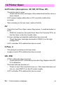
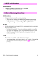
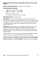
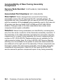
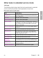
Infrared Port Not Responding
Situation
[he connection cannot be established or the transmission seems
o be taking longer than usual.
Solution
Make sure the device you are using is lrDAcompliant; look for an lrDA symbol on the
device or refer to the manual for the device for
kDA specifications.
Make sure that the operating system on your
computer includes arl IR driver and yol.u
application uses a HP LaserJet 5P/5MP
compatible printer driver.
Make sure you have positioned the device
within the range of operation and that no
objects, such as a finger, paper, books, or
bright light, are interff?ring with the connection.
Also make sure the two IR ports are clean (free
from dirt and grease).
Bright light of any kind (sunlight, incandescent
light, fluorescent light, or light from an nfrared
remote control, such as those used for TVs and
VCRs) shining directly into one of the IR ports
may cause interference.
Position the device closer to the IR poll on the
printer.
[he printer prints only part of a
)age or document.
The connection has been broken during
transmission. If you move the portable device
during transmission, the connection can be
broken. kDA-compliant devices are designed to
recover from temporary connection
interruptions. Re-establish the connection
(depending on the device you are using, you
can have anywhere from 3 to 40 seconds to reestablish the connection).
65
HP LaserJet 5P Printer Service Supplement
,,,
,.
Solution
Situation
The print job has been properly
sent to the printer, but the printer
will not print,
If the connection is broken before the entire
print job has been transmitted to the printer
(printing has not yet started), the printer may
not print any of the job, If the Data light is on,
press the RESET button to clear the printer’s
memory. Then, position the device within the
range of operation, and print the job again.
The IR status light turns off during
transmission.
The connection may have been broken. If the
Data light is on, press the RESET button to
clear the printer’s memory, Then, position the
device within the range of operation, and print
the job again.
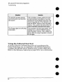
Using the Infrared Test Tool
A special infrared troubleshooting test tool manufactured by
Genoa Technology, Inc. in cooperation with Hewlett-Packard is
available through HP Direct Ordering (part number 5062-4461).
Refer to the discussion beginning on page 22 for more information.
66
HP LaserJet 5P Printer Service Supplement
Troubleshooting
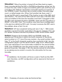
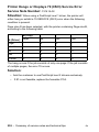
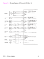
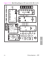
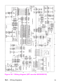
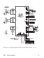
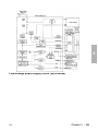
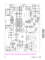
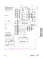
1/0
=00000=
lUEM: rEml
L-–--,
FORMAITER
=W
PCA
~
MEMORY
I
II
.,
l_l
1
-
.-
—--1--,
w
1,-
r————
I 11111
r
Ill
1111
T,,” 1
Wil
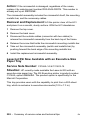
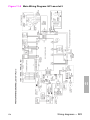
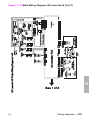
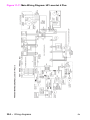
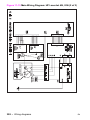
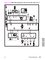
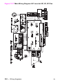
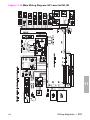
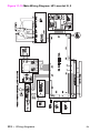
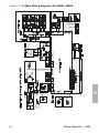
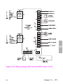
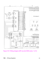
Figure 28
Main Wiring Diagram
67
HP LaserJet 5P Printer Service Supplement
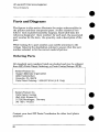
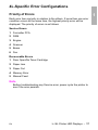
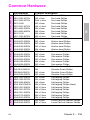
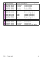
Parts and Diagrams
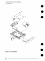
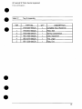
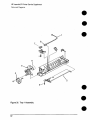
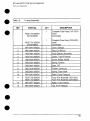
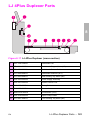
Parts and Diagrams
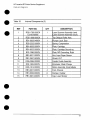
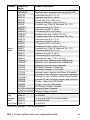
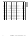
The figures in this section illustrate the major subassemblies in
the printer and their component parts. A table (material list)
follows each exploded assembly diagram. Each table lists the
reference designator (item number) for each part, the associated
part number for the item, the quantity, and a description of the
part.
While looking for a part number, pay careful attention to the
voltage listed in the description column to ensure that the part
number selected is for the correct model of printer.
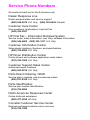
Ordering Parts
All standard part numbers listed are stocked and may be ordered
from HP’s Parts Direct Ordering, or Parts Center Europe (PCE).
Hewlett-Packard
Co.
Support Materials Organization
8050 Foothills Blvd.
Roseville, CA 95678
Parts Direct Ordering:
1-800-227-8164
(U.S. Only)
Hewlett-Packard
Co.
Parts Center, Europe
Wolf -Hirth Strasse 33
D-7030 Boeblingen,
Germany
(49 7031) 14-2253
Contact your local HP Parts Coordinator
numbers.
68
for other local phone
HP LaserJet 5P Printer Service Supplement
Parts ;and Diagrams
Ordering Consumables
●
Consumables and accessories such as those listed on page 8-5, and
in Table 4-1, Chapter 4, maybe ordered direct fkom
Hewlett-Packard.
The phone numbers are:
U. S.: 1-800-538-8787
Canada:
1-800-387-3154
(Toronto) 416-671-8383
United Kingdom: 0734-441212
Germany:
0130-3322
Contact your local HP Parts Coordinator
numbers.
NC)!(?
for other local phone
Parts that have no reference designator cm-part
number are not field replaceable parts aad
cannot be ordered through SMO.
69
HP LaserJet 5P Printer Sewice Supplement
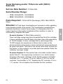
Parts and Diagrams
19
I
-
18
K&3-l,
13
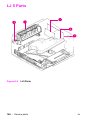
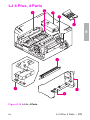
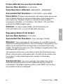
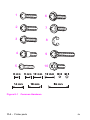
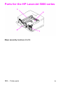
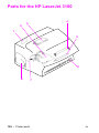
Figure 29. HP LaserJet 5P Covers and Doors
70
HP LaserJet 5P Printer Service Supplement
Parts and Diagrams
●
●
●
●
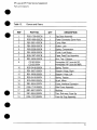
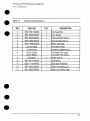
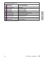
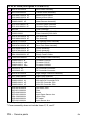
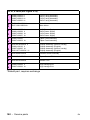
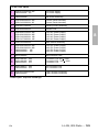
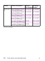
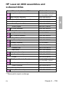
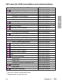
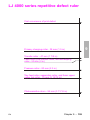
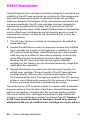
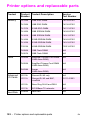
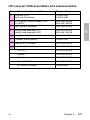
Table 12.
Covers and Doors
DESCRIPTION
REF
PART NO.
QTY
1
RG5-I 709-OOOCN
1
Top Door Assembly
2
RG5-1699-OOOCN
1
Power Connector Cover ASSY
3
RBI -5931 -OOOCN
1
Cover, Main
4
RB1 -5935-OOOCN
1
Button, Lock
5
RS5-2228-OOOCN
1
Spring, Compression
Guide, Lock Button
6
RBI -5936-OOOCN
1
7
RG5-1697-OOOCN
1
Paper Feed Tray Assembly
8
RBI-5939-OOOCN
1
Arm, Tray 1 Sensor
9
C31 50-00004
C31 55-00001
1
Nameplate (HP LaserJet 5P)
Nameplate (HP LaserJet 5MP)
10
RS5-2418-OOOCN
1
Spring, “Torsion
11
RBI-5937-OOOCN
1
Stopper, Hinge, Right
12
RBI -5938-OOOCN
1
Stopper, Hinge, Left
13
RS5-2419-OOOCN
1
Spring, Torsion
14
RF5-0593-OOOCN
1
Brush, Mirror
15
RBI-5934-OOOCN
1
Cover, Interface Connector
16
RG5-171 O-OOOCN
1
Side Cover Assembly
17
RB1-5927-OOOCN
1
Bushing
18
RB1-5924-OOOCN
1
Tray, Sub-assy, Face-Up
19
RG5-1707-OOOCN
1
Face-Up Tray Assembly
71
HP LaserJet 5P Printer Service Supplement
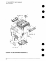
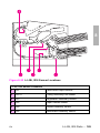
Parts and Diagrams
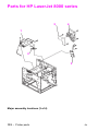
1
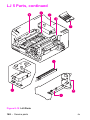
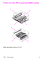
See Figure 33
4
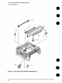
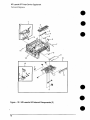
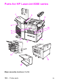
Figure 30. HP LaserJet 5P Internal Components
72
(1)
HP LaserJet 5P Printer Service Supplement
Parts and Diagrams
Table 13.
Internal Components
(1)
PART NO,
1
RG5-I 801 -OOOCN
1
Fan Assembly
2
RB1-6006-OOOCN
1
Arm, Sensor
3
RB1 -6332-OOOCN
1
M
4
RG5-1692-OOOCN
5
RG5-1799-OOOCN
1
MAssv
(tray 2)
Motor A:jsembly
6
C3150-00005
1
Formath?r Shield
7
C3152-69001
1
Postscript SIMM (exch.)
8
C3151 -67901
C3151 -69001
1
Formatt{?r PCA (new)
Formatt~?r PCA (exch,)
9
0515-2701
2
TORX screws
1
Leaf Spring
10
RBI -5971 -OOOCN
I
DESCRIPTIONI
REF
QTY
Roller (fray 2)
11
RG5-171 3-OOOCN
1
Gear train Assembly
12
RBI-5999-OOOCN
1
Plate, Groundino, Left
13
RBI-5998-OOOCN
1
Plate, Grounding, Right
73
HP LaserJet 5P Printer Service Supplement
Parts and Diagrams
Figure 31. HP LaserJet 5P Internal Components (2)
74
HP LaserJet 5P Printer Service Supplement
Park and Diagrams
●
InternalComponents
Table 14.
REF
I
PART NO.
(2)
I
QTY
DESCRIPTION
I
1
RG5-0683-020CN
1
Roller, Upper Output Assembly
2
XA9-0666-OOOCN
2
Screw, TP
3
RG5-I 786-OOOCN
1
Mirror Assembly
4
RB1-5873-OOOCN
1
Roller, Transfer
5
RS5-0313-OOOCN
1
Gear,”1 7T
5a
RF5-1287-OOOCN
1
Transf~?r Roller Assembly
6
RG5-1706-OOOCN
1
Transff?r Guide Assemb~
7
RG5-0675-OOOCN
1
Transf[?r Mount Assy, Riqht
8
RG5-0674-OOOCN
1
Transft?r Mount Assy, Left
9
RG5-0694-020CN
1
Switch, Plunger Assembly
10
RG5-0766-030CN
1
Scanner Connector Assy
11
RG5-0682-030CN
4
Lower Delivery Roller
75
HP LaserJet 5P Printer Service Supplement
Parts and Diagrams
Figure -32.
76
HP LaserJet 5P Internal Components
(3)
HP LaserJet 5P Printer Service Supplement
Parts and Diagrams
●
Internal
Table 15.
I
REF
I
(3)
Ccwmpw-lenki
PART NO.
1
RG5-1780-OOOCN
C31 50-69005
I
QTY
I
DESCRIPTION
I
1
Laser Scanner Assembly (new)
Laser Scanner Assembly (exch.)
2
RG5-1698-OOOCN
1
TOP Oblique
3
RBI-3002-040CN
1
Plunger
4
RS5-2232-OOOCN
1
Spring, Compression
Roller Assy
Lock, Door
5
RB1 -6003-OOOCN
1
Plate, Cartridge
6
RBI -6002-OOOCN
1
Plate, Cartridge
7
RF5-I 286-OOOCN
1
Plate, MP Grounding,
8
RBI -6001 -OOOCN
1
Arm, Input Paper Sensor
Grounding
Right
9
RBI -2987-020CN
1
Shield, HVT
10
RG5-0584-OOOCN
1
Feeder Guide Assembly
11
RF5-1283-OOOCN
1
Eliminator, Static CharG[?
12
RG5-I814-OOOCN
1
Roller Assembly, Small Media
13
RBI-6007-OOOCN
4
Foot, Chassis
14
RBI-6008-OOOCN
6
Damper, Rubber
15
RBI -3681 -OOOCN
1
Cap, Laser Shutter
77
HP LaserJet 5P Printer Service Supplement
Parts and Diagrams
Flow
—1
—2
I
I
C@
/’”.
,0
@
Figure 33. DC Controller Assembly
78
/“
.
\,
HP LaserJet 5P Printer Service Supplement
Parts arid Diagrams
Table “16.
DC Controller Assembly
REF
PART NO.
QTY
DESCRIPTION
1
RG5-I719-OOOCN
1
HVT Controller Assembly
2
RH2-5259-OOOCN
1
Cable, Flat
3
RG5-171 2-OOOCN
1
DC Controller Case Assy
4
RG5-I 808-OOOCN
1
Tray 1 Connector PCA Assy
5
RBI -5987-OOOCN
1
Shield, Case
1
DC Controller
(new)
(exchange)
PCA (1 OCI-I20V)
RG5-1798-OOOCN
C3150-69001
DC Controller
PCA (220-240V)
RG5-1809-OOOCN
C31 50-69002
(new)
(exchange)
6
79
HP LaserJet 5P Printer Service Supplement
Parts and Diagrams
A
Figure 34, Tray 2 Assembly
80
HP LaserJet 5P Printer Service Supplement
Parts and Diagrams
Table “17’.
Tray2 Assembly
REF
PART NO.
QTY
R75-4000-OOOCN
1
Complete Tray 2 Assemol
RF5-0673-OOOCN
1
Plate, Side
1
DESCRIPTION
2
RS5-2458-OOOCN
1
Spring, Compression
3
RBI-3426-OOOCN
1
Claw, Separation
4
RB1-6378-OOOCN
1
Tray, Legal
5
RBI-3338-OOOCN
1
Plate, E%d
3
81
HP LaserJet 5P Printer Service Supplement
Parts and Diagrams
\
&’
Figure 35. Tray 1 Assembly
82
/’
HP LaserJet 5P Printer Service Supplement
Parts and Diagrams
●
-r?dbk? 18,
REF
a
Tray 1 Assembly
DESC
PART NO.
QTY
RG5-I 695-OOOCN
1
Complete Tray 1 Pickup Ass
1
RG5-I 804-OOOCN
1
Tray 1 Sensor Cable
2
RG5-1694-OOOCN
1
Paper guide Plate Ass
3
RS5-2415-OOOCN
1
Sprina, Compression
4
RH7-1258-OOOCN
1
Solenoid SL2
5
RG5-1693-OOOCN
1
Tray 1 F)ickup Roller Ass
6
RBI -2205-OOOCN
1
Roller, Tray 1 Picku
7
RF5-0343-OOOCN
1
Pad, Se~aration
8
WG8-521O-OOOCN
1
Photosensor
PS5
s
83
HP LaserJet 5P Printer Service Supplement
Parts and Diagrams
@
●
Figure 36. HP LaserJet 5P Fusing Assembly
●
84
HP LaserJet 5P Printer Service Supplement
Parts and Diagrams
●
‘-ram? 19.
REF
FM-Q
Assembly
PART NO.
DESCRIPTION
QTY
1
Complete FuserAssy(100-120V)
(new)
(exchange)
1
Complete Fuser Assy (’220-240V)
(new)
RG5-I 700-OOOCN
C31 50-69003
RG5-1 701 -OOOCN
C3150-69004
1
RBI -5918-OOOCN
1
(.f@2Ne)
Cover, Delivery
2
RBI -3097-OOOCN
1
Flao, Exit Sensor
RG5-0681-OOOCN
4
Fuser Delivery Assembly
RG5-I813-OOOCN
1
Guide, Fuser Entrance
5
XB2-8300-809CN
2
Screw, VV/Star, M3X8
6
RS5-2421-OOOCN
1
Sprinq, Tension
7
RS5-0637-OOOCN
1
Gear, 24T
8
9
RB1 -3109-OOOCN
1
Rubber, Continuity
RS5-2421-OOOCN
1
Spring, Fuser Hook
10
RB1 -591 O-OOOCN
1
Roller, Fuser Pressure
11
RG5-1702-OOOCN
RG5-I 703-OOOCN
1
Fuser Film Assembly (100-1 20v)
Fuser Film Assembly (220-240V)
12
RBI -5917-OOOCN
1
Roller, Fuser Delivery
RB1-5906-OOOCN
1
Tab, Fuser Release
3
d
13
85
HP LaserJet 5P Printer Service Supplement
Accessories
Accessories
Listed below are the accessories and supplies, including
supplemental documentation you can order for your HP LaserJet
5P or 5MP printer.
Pari Number
Option
Toner Cartridge
Memory upgrades
C3903A
1 MByte-C3130A
~2 MByte-C3131A
4 MByte-C3132A
8 MByte-C3133A
t6MByte-C3148A
Descriptionor Use
Replacement toner cartridge.
Adds up to 48 MBytes of memory to the HP LaserJet 5P
printer, for a total of 50 MBytes. Adds up to 32 MBytee of
memory to the HP LaserJet 5MP printer, for a total of 35
MByles.
Adobe’s PostScript Level 2
SIMM for the HP LaserJet
5P
C3152A
Adds PostScript Level 2 language and 1 MByte of memory
to the HP LaserJet 5P printer includes software for
Macintosh, VVindowe 3.1 and 3.1 t, and “HP LaserJet 5MP
Macintosh Notes” (factory-installed in the 5MP printer).
IEEE-1284 Parallel Cable
2 Meter A to B-C2950A
3 Meter A to e-C2951A
3 Meter A to C-C2946A
10 Meter A to CGC2947A
lEEE-t 284-compliant cables, where:
A=host computer connector (A-type)
B=large prhrter connector (B-type)
C=small printer connector (C-type)
LocalTalk Network cable
for Macintosh
92215N
Connect to a LocalTalk Network.
Serial printer cable for
Macintosh
922t
HP JetDirect EX ptint
servers (external)
J2382B
J2383B
J2593A
J2594A
Ethernet (1 parallel ports)
TokenRing (1 parallel ports)
Ethernet (3 parallel ports)
TokenRing (3 parallel fMrts)
HP Printer Pal (externel)
C2971 A
Printer fax aueeeory. Allows faxes to be printed by the
printer; faxes can also be sent electronically from the PC.
AvailabWy outside the US may vary.
Extra Paper Cassette (Tray
2)’
R75-4000-OOOCN
Universal tray.
lrDA Test Tool
5062-4661
Infrared communications test tool manufactured by Genoa
Technologies, Inc.
5s
Directly connect to a Macintosh computer.
* This item must be ordered through HP Parts Direct Ordering, (800) 2278164. Outside the U. S., eee “Parts and Diagrams earlier in this appendix.
86
Index
DC controller 78
fusing assembly 84
internal components
printer parts 4
tray 1 assembly 82
tray 2 assembly 80
wiring 67
DMO 69
documentation
8-9
drivers 9
20 MEM OVERFLOW
56
21 PRINT OVERRUN
56
22 IO ERROR 56
40 ERROR 57
41 ERROR 57
50 FUSER ERROR 60
51 ERROR 57
52 ERROR 57
55 ERROR 57
57/58 MOTOR ERROR 61
61.x SIMM ERROR 62
62 MEMORY ERROR 63
62.x SIMM ERROR 62
63 MEMORY ERROR 63
64 ERROR 64
64 SCANNER ERROR 63
65 ERROR 64
68 SERVICE ERROR 57
M
Economode
3
erasing memory with RESET
error
clearing with RESET 11
continuable
56
data 14
fatal
15,60
hardware-related
infrared
65
A
accessories
86
automatic I/O switching
26
B
hi-directional communication
books available 8-9
buttons
GO 10
power 4
RESET 10
status panel 10
26
11
11
IR port 15
light patterns 56
memory 58
14
recoverable
secondary 56
service 60
SIMM .14,58
error light 11, 14
F
c
cables
IEEE-1284 compliant 26
clearing memory with RESET
cold reset 30
connections
network 26
consumables
life 36
ordering 69
72, 74, 76
10
D
data light 12
DC controller 78
interconnect
49
removal and replacement
51
default settings, returning to 11
demo page 10,30,33
diagnostic 30
diagrams
covers and doors 70
fax accessory 86
features 10-29
product information 3
flashing lights 11
fonts 3
temporary, removing with RESET
formatter
removal and replacement
47
fusing assembly 84
removal and replacement
50
11
G
GO button
grounding
10,32,56
25
I
I/O buffering 28
I/O cover
removal and replacement
1/0 switching 26
IEEE-1284
B-Type, C-Type 25,26
39
1
cables, compliant 26
parallel ports 25-26
specifications
26
infrared
communication
18
interface 3
operation 21
port 4, 10
printing 20
software 18
status light 4, 10, 12, 15, 20
test tool 22,23, 66,86
troubleshooting
22, 65,66
using ta print 20
interface cables 25-26
interfaces 25
I/O switching 26
internal components
72, 74, 76
IrDA, print using 20
J
JetDirect
86
L
LED
patterns 58
LED
patterns 56
LED patterns 13
LEDs, status 11
left side cover
removal and replacement
light
patterns 13,56,58
lights on status panel
described 11
lights, status 11
LocalTalk interface 3
LocalTalk port 25
40
M
Macintoeh
reference manual available
macros, temporary
11
main wiring diagram 67
media path 16-17
memory 3
and 1/0 buffering 28
and resource saving 27
clearing with RESET 11
error 58, 62
ordering 86
SIMM removal 39
model number 5
monthly usage
3
2
8-9
N
network, connecting to
networks 26
NVR.AM 32
26
0
ordering
books 8-9
consumables
69
LocalTalk
86
parts 68
Postscript
86
P
pages, self-test 10,33
panel
See status panel
paper
jams 11
movement, overview (theory)
path 16-17
size 3
specifications
8-9
trays 3,4, 86
paper-out flag 43
parallel cable 26
parallel interface 3
parallel ports 25
parts
ordering 68, 86
Parts Center Europe (PCE) 68
parts and diagrams 68-85
parts, location 4, 17
PCE 68
PCL
self-test page 33
phone numbers
DMO 69
ordering consumables
69
PCE 68
SMO 68
PJL commands 30-35
port
infrared 19
POrtS
25
PostScript, SIMM removal 39
power door
removal and replacement
39
power switch 4
print speed 3
print spoolers 26
printer
diagram 4
lights 11
parts diagram 4
serial number 5
printer configuration
30
printer languages 3
printer settings
returning to defaults 11
16
protocol
infrared
0
●
T
18
R
ready light 12
reference guides 8-9
regulato~- information
5
removal and replacement
37
DC Controller 51
formatter 47
fusing assembly 50
1/0 cover 39
left side cover 40
power door 39
tools 38
top cover 41
Tray 1 assembly 44
removing fonts, macros 11
required tools 38
requirements
for infrared 19
RESET button 10, 32, 56
resetting your printer 11
resolution 3
resource Saving 27
modes 27
resuming printing 10
s
●
m
temporary fonts, macros I 1
test pages 10,32-33
test tool 66,86
infrared 23
toner, ordering 86
tools, required 38
top cover
removal and replacement
41
tray
empty :13-14
tray 1
assembly 82
removal and replacement
44
light 12,
tray 2
empty indicator
12
assembIy 80
light 12
troubleshooting
55-67
infrared 22
troubleshooting, IR port 22
turning on your printer 4
typefaces see fonts 3
w
wireless printing
See see infrared
wiring diagram 67
self test 30, 33
self-test
explained 35
pages 10, 33
serial number 4, 5
service mode 30-35
settings
rekning
to defaults 11
SIMM
error 14, 58, 62
removal 39
SMO 68
software 19
shipped with printer 9, 18
space requirements
6
specifications
acoustic 7
dimensions
6-7
electrical 7
environmental
7
IrDA 18
spoolers 26
status panel 3,4, 10
GO button 10-11
Iights 11
RESET button 10
supplementary documents 8-9
Support Materials Organization
(SMO) 68
switchboxes
26
switching, 1/0 26
3
4
. ...
.’.
May 1998 Edition
HP LaserJet Family
Quick Reference
Service Guide
Volume I
HP LaserJet Family
Quick Reference
Service Guide
Volume I
© Copyright Hewlett-Packard
Company 1998
All Rights Reserved.
Reproduction, adaptation, or
translation without prior written
permission is prohibited, except
as allowed under the copyright
laws.
Publication number
5021-8943
First edition, May 1998
Warranty
The information contained in this
document is subject to change
without notice.
Hewlett-Packard makes no
warranty of any kind with respect
to this information.
HEWLETT-PACKARD
SPECIFICALLY DISCLAIMS
THE IMPLIED WARRANTY OF
MERCHANTABILITY AND
FITNESS FOR A PARTICULAR
PURPOSE.
Hewlett-Packard shall not be
liable for any direct, indirect,
incidental, consequential, or other
damage alleged in connection
with the furnishing or use of this
information.
Hewlett-Packard Company
11311 Chinden Boulevard
Boise, Idaho 83714 U.S.A.
Trademark credits
Adobe and PostScript are registered
trademarks of Adobe Systems, Inc.,
which may be registered in certain
jurisdictions.
Microsoft® is a U.S. registered
trademark of Microsoft Corporation.
MS-DOS® is a U.S. registered
trademark of Microsoft Corporation.
UNIX is a registered trademark in the
United States and other countries,
licensed exclusively through X/Open
Company Limited.
Contents
1
Control panel messages . . . . . . . . . . . . . . . . . . . . . . . 7
2
Service mode . . . . . . . . . . . . . . . . . . . . . . . . . . . . . . . 73
3
Power supply . . . . . . . . . . . . . . . . . . . . . . . . . . . . . . . 81
4
Input/Output (I/O) . . . . . . . . . . . . . . . . . . . . . . . . . . . . 93
5
Media specifications . . . . . . . . . . . . . . . . . . . . . . . . 107
6
Toner cartridge information . . . . . . . . . . . . . . . . . . 121
7
Printer options and user replaceable parts . . . . . . 131
8
Service parts. . . . . . . . . . . . . . . . . . . . . . . . . . . . . . . 147
9
Summary of service notes and technical tips . . . . 197
10 Image defects . . . . . . . . . . . . . . . . . . . . . . . . . . . . . . 273
11 Wiring diagrams . . . . . . . . . . . . . . . . . . . . . . . . . . . . 313
12 Services, support, and training . . . . . . . . . . . . . . . 335
13 Hewlett-Packard LaserJet Companion . . . . . . . . . . 343
Appendix . . . . . . . . . . . . . . . . . . . . . . . . . . . . . . . . . . . . . 347
Index . . . . . . . . . . . . . . . . . . . . . . . . . . . . . . . . . . . . . . . . . 351
EN
iii
Ordering Other Manuals
This HP LaserJet Family Quick Reference Service Guide was created
to help the LaserJet Service Engineer quickly troubleshoot common
printer problems. While this reference is intended to provide all of the
information the Service Engineer will need for on-site repair of
HP LaserJet products, it is not intended to replace the service manual
for any HP LaserJet product. For detailed information about the
HP LaserJet products described in this guide, see the user guide or
service manual for that product.
Service manuals for HP LaserJet products are available from the
HP Support Materials Organization (SMO). The Service Parts Order
Desk number is:
(800) 227-8164 (U.S. Only)
If you are located outside of the U.S., contact your local HP Sales and
Service office.
iv
EN
Supported Products
This service guide supports the following printers:
Printer Name
HP LaserJet Companion
(minimal support only)
HP LaserJet 6L
HP LaserJet 5Si Mopier
HP LaserJet 5Si/5Si MX
HPLaserJet 5L
HP LaserJet 6P/6MP
HP LaserJet 5P/5MP
HP LaserJet 5/5M/5N
HP LaserJet 4V/4MV
HP LaserJet 4P/4MP
HP LaserJet 4L/4ML
HP LaserJet 4+/4M+
HP LaserJet 4/4M
HP LaserJet 4Si/4Si MX
HP LaserJet IIISi
HP LaserJet IIIP
HP LaserJet IIP+
HP LaserJet IIP
HP LaserJet IIID
HP LaserJet III
HP LaserJet IID
HP LaserJet II
HP Classic LaserJet (2686D)
HP Classic LaserJet (2686A)
Printer Abbreviation
LJ Companion
LJ 6L
LJ 5Si Mopier
LJ 5Si LJ 5Si MX
LJ 5L
LJ 6P LJ 6MP
LJ 5P LJ 5MP
LJ 5 LJ 5M LJ 5N
LJ 4V LJ 4MV
LJ 4P LJ 4MP
LJ 4L LJ 4ML
LJ 4+ LJ 4M+
LJ 4 LJ 4M
LJ 4Si LJ 4Si MX
LJ IIISi
LJ IIIP
LJ IIP+
LJ IIP
LJ IIID
LJ III
LJ IID
LJ II
LJ 2686D
LJ 2686A
Note
The abbreviation for each printer name is used in the text.
.
EN
v
Reference
Name Used
in this Guide
Model Number
Maximum
Pages per
Month
Service Manual
Part Number
LJ 6L
5Si Mopier,
LJ5Si MX/5Si*
LJ 5L
C3990A
C3166A/C3167A
C4076A/C4077A
C3941A
6K
100K
C3990-99001
C4077-99015
4K
C3990-99001
LJ 6P/6MP*
5P/5MP*
LJ 5/5M*/5N
C3150A/C3155A/
C3980A/C3982A
C3916A/C3917A/
C3952A
12K
C3980-99001
35K
C3916-90984
LJ 4V/4MV
C3141A/C3142A
50K
C3141-90929
LJ 4P/4MP*
C2005A/C2040A
8K
C3980-90956
LJ 4L/4ML*
C2003A/C2015A
8K
C3980-90956
LJ 4+/4M+*
C2037A/C2039A
20K
C3916-90984
LJ 4/4M*
LJ 4Si/4SiMX*
C2001A/C2021A
C2010A/C2011A
20K
75K
C3916-90984
C2010-90939
LJ IIISi
LJ IIIP
33491
33481
50K
8K
C2010-90939
33481-90951
LJ IIP+
LJ IIP
C2007A
33471
8K
6K
33481-90951
33481-90951
LJ IIID
33459
20K
33459-90906
LJ III
33449
16K
33449-90906
LJ IID
LJ II
33447
33440
16K
12K
33459-90906
33449-90906
Classic LJ
2686D
Classic LJ
2686A
2686D
15K
02686-90920
2686A - 2686A+
12K
02686-90920
*Macintosh-compatible
vi
EN
1
Control panel
messages
Overview
This chapter provides information on the display lights on the
HP LaserJet 6L, 5L, 6P, 5P, and 4L printers and includes illustrations
and detailed error codes for all printers. Error codes are listed as they
appear on the printer display. Not all codes are included as many are
self-explanatory.
Note
Displays shaded in color represent primary lights. Displays that are
not shaded represent secondary lights. To view the secondary lights
on the printer, press [Go] and [Reset/Job]Cancel] simultaneously.
EN
Overview – 7
LJ 6L, 5L Printer Light-Emitting Diode
(LED) Displays
See the legend that follows for a description of the error and the action
to remedy it.
STATUS MESSAGES
1. Error LED is on.
(*Unclearable error)
2. Error LED is
blinking.
3. All LEDs are
blinking.
4. Data LED is
blinking.
Error
Data
Ready
5. All LEDs are off.
When all the lights are on, there is a Service error. Press and hold the
front panel button to display the LED error code pattern. The code will
be shown only while the button is pressed. The following pictures
show the possible LED error patterns.
1. Error LED is on.
(*Unclearable error)
2. Ready LED is on.
3. Error and Ready
LEDs are on.
4. Error and Data
LEDs are on.
5. Data LED is on.
6. All LEDs are on.
7. Data and Ready
LEDs are blinking.
8. Formatter error.
* An unclearable error is not strictly a service message. It will appear
without all three lights being displayed first. See item 1 in the following
table.
8 – Control panel messages
EN
Legend (6L, 5L Display Lights)
Status Messages
Item
Description
Recommended Action
1
Paper out
Door open
No Electro-photographic (EP)
cartridge
Paper jam
See page 21
See page 18
2
Memory error
See page 34
3
Incompatible memory card
See page 49
4
Manual feed
See page 70
5
Sleep mode
See page 69
See page 32
See page 26
Error and Service Messages
Item
Description
Recommended Action
1
Unclearable error
Engine error
See item 1, above
See page 39
2
ROM/RAM error
See page 50
3
Fuser error
See page 44
4
Beam error
See page 45
5
Scanner error
See page 47
6
Formatter PCA error
See page 57
7
Firmware error
See page 61
8
Formatter PCA error
See page 57
Note
Before troubleshooting any service error, power cycle the printer to
see if the error persists.
EN
LJ 6L, 5L Printer Light-Emitting Diode (LED) Displays – 9
1
LJ 6P Printer LED Displays
See the legend that follows for a description of the error and the action
to remedy it. If both the error and data lights are lit, simultaneously
press [Go] and [Reset/Job[Cancel] to display the Data Error pattern.
LJ 6P Printer LED Displays
STATUS
Error
Data
Ready
Tray 1
Tray 1
LED Blinking
Tray 2
CONTINUABLE ERRORS
SIMM ERRORS
FATAL ERRORS
Primary
* To view secondary lights press the [Go] and
buttons simultaneously.
10 – Control panel messages
* = Any other combination
Secondary
[Reset/Job[Cancel]
EN
Legend (6P Display Lights)
Status Messages
Item
Description
Recommended Action
1
Paper out (Tray 1)
See page 21
2
Paper out (Tray 2)
See page 21
3
Printer open
No toner cartridge
Paper jam
See page 18
See page 32
See page 20
4
Manual feed
See page 70
Continuable Errors
When the ERROR and DATA LEDs are on, press [Go] and [Reset]
simultaneously. Follow the instructions for the secondary light patterns
shown.
Item
Description
Recommended Action
5
Primary light pattern
See note on primary and
secondary lights, page 13
5-1
Error 20 (memory overflow)
See page 34
5-2
Error 21 (print overrun)
See page 35
5-3
Error 22 (I/O error)
See page 36
5-4
Error 40
See page 38
5-5
Error 41.1, 41.2, 41.3
See page 40
5-6
Error 68, 68.1
See page 64
5-7
Error 51 (beam detect)
See page 45
5-8
Error 52 (scanner malfunction)
See page 47
5-9
Error 55
See page 53
EN
LJ 6P Printer LED Displays – 11
1
SIMM Errors
Remove all SIMMs and power cycle the printer. Retry the operation.
Replace the SIMMs one at a time to locate the defective module. Refer
to the Service Manual for details.
Item
Description
Recommended Action
6
Error 53-0 ROM error
See note below
7
Error 53-1 RAM error
See note below
Fatal Errors
When the DATA, TRAY 2, TRAY 1, and ERROR LEDs are on, press [Go]
and [Reset] simultaneously and follow the instructions for the secondary
light patterns shown.
Item
Description
Recommended Action
8
Primary light pattern
See note on primary and
secondary lights, page 13
8-1
Error 50 fuser
See page 44
8-2
Error 57/58 (main motor)
See page 54
8-3
Error 61.x (x=1, 2, 3 SIMM)
See page 58
8-4
Error 62.x (x=1, 2, 3 SIMM)
See page 59
8-5
Error 62.0
See page 58
8-6
Error 63, 64, 64, 65
See pages 59–60
8-7
All other errors
See pages 61–72
12 – Control panel messages
EN
LJ 5P Printer LED Displays
See the legend that follows for a description of the error and the action
to remedy it. If both the error and data lights are lit, simultaneously
press [Go] and [Reset] to display the Data Error pattern.
LJ 5P Printer LED Displays
STATUS
Error
Tray 1 (MP Tray)
Tray 2 (Paper Cassette)
Data
Ready
CONTINUABLE ERRORS
SIMM ERRORS
FATAL ERRORS
Any Combination
Primary
* To view secondary lights press [Go] and
EN
Secondary
[Reset.
LJ 5P Printer LED Displays – 13
1
Legend (5P Display Lights)
Status Messages
Item
Description
Recommended Action
1
Paper out (Tray 1)
See page 21
2
Paper out (Tray 2)
See page 21
3
Printer open
No toner cartridge
Paper jam
See page 18
See page 32
See page 20
Continuable Errors
When the ERROR and DATA LEDs are on, press [Go] and [Reset]
simultaneously. Follow the instructions for the secondary light patterns
shown.
Item
Description
Recommended Action
4
Primary light pattern
See note on primary and
secondary lights, page 13
4-1
Error 20 (memory overflow)
See page 34
4-2
Error 21 (print overrun)
See page 35
4-3
Error 22 (I/O error)
See page 36
4-4
Error 40
See page 38
4-5
Error 41.1, 41.2, 41.3
See page 40
4-6
Error 68, 68.1
See page 64
4-7
Error 51 (beam detect)
See page 45
4-8
Error 52 (scanner malfunction)
See page 47
4-9
Error 55
See page 53
14 – Control panel messages
EN
SIMM Errors
Item
Description
Recommended Action
5
Error 53-0 ROM error
See note below
6
Error 53-1 RAM error
See note below
Note
Remove all SIMMs and power cycle the printer. Retry the operation.
Replace the SIMMs one at a time to locate the defective module. Refer
to the Service Manual for details.
Fatal Errors
When the DATA, TRAY 2, TRAY 1, and ERROR LEDs are on, press [Go]
and [Reset] simultaneously. Follow the instructions for the secondary
light patterns shown.
Item
Description
Recommended Action
7
Primary light pattern
See note on primary and
secondary lights, page 13
7-1
Error 50 fuser
See page 44
7-2
Error 57/58 (main motor)
See page 54
7-3
Error 61.1/62.1
See page 58
7-4
All other errors
See 79 Error, pages 61-71
8
Error 63 service error
See page 59
EN
LJ 5P Printer LED Displays – 15
1
LJ 4L Printer LED Displays
Recoverable Errors
For more details, see the page number provided.
Error
Paper
Data
Ready
LED Legend
RECOVERABLE ERRORS (Displayed on single lights)
Paper Out
(See page 23)
Printer Open
(See page 24)
Paper Jam
(See page 26)
21 Print Overrun
(See page 35)
Paper LED on
steady.
Error LED on steady.
Paper LED is
blinking.
Error LED is blinking.
SERVICE ERRORS (Displayed while pressing front panel button)
Service Error
All 4 LEDs are on.
50 Error/Service
(See page 42)
When all four lights are on, a service error is indicated. Press and
hold the front panel button to display the error code. The code will be
shown only while the button is pressed. The following pictures show
the possible error codes.
NOTE: If all four lights remain on, yet no error code is displayed
when pressing the button, power cycle the printer. If the condition
persists, replace the formatter PCA.
51 Loss of Beam
52 Incorrect Scanner 53 Accessory
Detect
Speed
Memory Error
(See page 45)
(See page 47)
(See page 49)
Ready and Error
LEDs are on.
55 Engine
(See page 53)
Data and Error LEDs
are on.
58 Fan
(See page 56
Paper and error
LEDs are on.
61.x Formatter
(See page 58)
Error LED is on.
Ready, Data, and
Error LEDs are on.
Error LED is off;
other LEDs display a
pattern.
16 – Control panel messages
Data LED is on.
Blank Display
(See page 68
All LEDs are off.
EN
4L-Specific Error Configurations
Priority of Errors
1
Each error has a priority in relation to the others. If more than one error
condition occurs at the same time, the highest priority error will be
displayed. The priority of errors is as follows:
Service Errors
1 Formatter PCA
2 RAM
3 Engine
4 Scanner
5 Beam
6 Fan
Recoverable Errors
1 Door Open/No Toner Cartridge
2 Paper Jam
3 Paper Out
4 Memory Error
5 Manual Feed
Note
Before troubleshooting any Service error, power cycle the printer to
see if the error persists.
EN
LJ 4L Printer LED Displays – 17
Error Codes
Clear Staple Jam
5Si Mopier
•
Clear the jam.
•
Check the staple cartridge.
•
Check the stapler and cabling.
•
Check the stapling unit control’s printed-circuit assembly (PCA).
•
Replace the entire stapling unit as required.
Close Printer Cover/Printer Open
All Printers
•
The printer door is open.
•
Check that the toner cartridge is fully seated and that the covers are
firmly closed.
•
The direct current (DC) power supply is defective.
•
The DC controller is defective.
•
The actuator or tab is missing or broken.
•
The paper control printed-circuit assembly (PCA) is defective.
18 – Control panel messages
EN
Install Toner Cartridge/No Cartridge
All Printers
•
Reseat or install a new toner cartridge.
•
The high voltage contacts are dirty or defective.
•
The high voltage power supply is defective.
1
LJ 5
•
The DC Controller is defective.
Install Tray 2
LJ 5
•
The lower cassette (Tray 3) is selected and the printer has detected
that the paper cassette (Tray 2) is not installed.
– Install or reseat the paper cassette (Tray 2), which is the paper
guide for the lower cassette (Tray 3).
•
The paper cassette (PC) is improperly fitted.
– Firmly reseat the PC.
Out of Staples Optional Output X
5Si Mopier
•
Replace the staple cartridge.
– If the message continues after the cartridge has been replaced,
check the stapler, top cover assembly, and cabling.
•
Check the stapling unit control PCA.
•
Replace the entire stapling unit if required.
EN
Error Codes – 19
Output Operation Condition x.yy
5Si Mopier
x=output device number
yy=condition code
For the multibin mailbox:
01 = face-up tray not installed
Note
See also the section on troubleshooting the 2,000-sheet input unit
and multibin mailbox/mailbox with stapler.
Remove Paper Jam
LJ 5
•
See 13 Paper Jam—all printers
•
The rear door is open.
•
The cassette paper out sensor flag is broken or missing.
•
The 500-sheet lower cassette is not properly adjusted (see service
note C2001A-04).
– Adjust the tray, using the instructions in the service note.
•
Check the transfer roller to ensure that it is properly seated.
•
The input sensor (PS1) or fuser exit sensor (PS3) is bad; or with
jams from the MP tray (Tray 1), the paper end sensor (PS5) is bad.
Staple Limit Reached
5Si Mopier
•
Send print jobs of only 20 pages or fewer to the stapler.
20 – Control panel messages
EN
Stapler Align Error
5Si Mopier
•
Remove the paper from the stapler and re-send the job.
Stapler Malfunction
5Si Mopier
•
Clear the stapler jam and re-send the job.
Stapler Supply Out
5Si Mopier
•
Load a new staple cartridge.
Toner Low
5Si, 5
•
The toner is uneven in the cartridge.
•
The toner cartridge contact points are malfunctioning.
•
The high-voltage power supply (HVPS) is defective.
Tray x Empty/x Load/Paper Out
All Printers
•
The paper tray is empty or is seated incorrectly.
•
The sensor arm is stuck or broken.
•
The tray-size sensor is defective or configured incorrectly.
– Verify the tray tabs and switches at the right rear (or right front) of
the tray slot, or configure the tray from the control panel.
– The paper control/sensor PCA is defective.
EN
Error Codes – 21
1
Warming Up
5Si, 5
•
Separate all accessories.
•
Power cycle the printer.
•
The formatter PCA is defective.
•
The DC controller is defective.
•
The power supply is defective.
02 Warming Up (if 3 Minutes)—See also
50 Error
4V
•
The Input/Output (I/O) cable is hooked up incorrectly or there is bad
I/O in the computer.
– Remove the I/O cables and power cycle the printer.
•
There are defective component(s).
– Replace the fusing assembly if it is not warming up the DC
controller, PCA power supply, or formatter PCA.
4Si/IIISi
•
The display cable or formatter PCA is defective.
IID, II
•
The I/O cable is hooked up incorrectly or there is bad I/O in the
computer.
– Remove the I/O cables. Replace the formatter PCA.
2686A/D
•
The DC power supply/main motor drive is defective.
22 – Control panel messages
EN
11 Paper Out (MP/PC/UC/LC/EC/LE LOAD)
All Printers
1
•
The paper tray is empty or is seated incorrectly.
•
The sensor arm is stuck or broken.
•
The tray-size sensing or configuration is defective.
– Verify the tray tabs and switches are at the right rear (or right
front) of the tray slot, or configure the tray from the control panel.
•
The paper control/sensor PCA is defective.
4L
•
The paper cassette is empty or missing.
•
The paper cassette is seated incorrectly.
•
The paper out flag PS2 is broken or stuck.
•
The DC controller PCA is defective.
•
Tray 1 (the MP tray) is empty.
– Add paper to Tray 1; then press [Go] to continue.
•
Tray 2 (the paper cassette) is empty.
– Add paper to the tray if it is on continuously; verify that the
sensor flag movement is not hindered.
EN
Error Codes – 23
12 Printer Open
All Printers (Exceptions: 4P, IIIP, IIP Plus, IIP)
•
The printer door is open.
– Check that the toner cartridge is fully seated and that the cover is
firmly closed.
•
A DC power supply malfunction or DC controller malfunction
occurred.
•
Tab is missing on the top cover; replace the tab.
4V
•
Check the front Door Open sensor flag sensor; it could be broken or
stuck.
– PS402 is located on the small Front Door Unit Terminal PCA, on
the front door under the transfer roller.
•
A toner cartridge microswitch malfunction has occurred.
– Check the toner cartridge microswitch (SW501) on the high
voltage PCA.
•
A DC controller PCA malfunction has occurred.
4 Plus, 4
•
The plunger is missing on the top cover.
•
A paper control PCA malfunction has occurred.
4Si, IIISi
•
A PS1 malfunction has occurred.
– Check that the PS1 is blocked by the latch flag. Replace the PS1
if it is defective.
•
The fuser bulb has burned out.
– Check to see if the fuser bulb turns on. If the fuser bulb does not
turn on, reset SW101 on the AC power supply.
•
A DC controller PCA malfunction has occurred.
24 – Control panel messages
EN
12 Open or No EP
4P
•
The top cover is open.
•
The toner cartridge is not installed.
•
There is a defective interlock switch assembly.
1
4L
•
Part of the top door that pushes the plunger down is broken.
•
The top door switch (plunger assembly) is broken.
IIIP, IIP Plus, IIP
•
The paper path door or top cover is open.
– Close the paper path door or top cover.
•
A toner cartridge is not installed or it is not seated.
– Replace or reseat the toner cartridge.
•
There is a defective fan, PS4, or PS5.
•
The external fuser access door is not closed.
EN
Error Codes – 25
13 Paper Jam/Remove Paper Jam
All Printers
•
The media does not meet HP specifications.
•
The paper path is dirty or obstructed.
– Clean the paper path components; ensure that the transfer roller
is seated properly.
•
The pickup (or other) rollers and/or the separation pad is worn.
•
The paper is the wrong length or the paper size is selected
incorrectly in the software.
•
The exit sensor or flag is defective.
•
A defective input (paper-out) sensor does not sense that the printer
is out of paper.
•
The paper cassettes are not correctly loaded.
•
The solenoid operation is bad.
– Verify proper solenoid operation and replace if necessary.
•
The gear(s) is bad or not meshing in the drive train.
– Replace the bad gear(s) or check the toner cartridge gears for
damage.
•
The main motor or drive circuit is bad.
•
The delivery mechanism or the coupler gear to the main drive is
bad.
•
The main motor drive circuitry is bad.
•
The DC controller is defective.
26 – Control panel messages
EN
5L, 6P, 5P
•
If all of the flags move properly and the connectors are seated, but
the error persists, replace the DC controller.
6P, 5P
•
There are paper fragments under the oblique rollers (top or front).
– Remove the rollers and the paper fragments.
4V
•
The toner cartridge gears are worn or damaged.
•
The paper path gears are worn or damaged.
•
The DC controller PCA is defective.
•
The registration guide is defective.
4P, 4L
•
The rear door of the printer is open.
•
The flags/sensors are stuck or broken.
•
There are paper fragments under the oblique rollers (top or front).
– Remove the rollers and clear out the paper.
•
The transfer roller guide is not seated.
4 Plus, 4
•
The rear door is open.
•
The cassette paper-out sensor flag is broken or missing.
•
The 500-sheet lower cassette is improperly adjusted (see service
note C2001A-01A).
– Adjust the tray according to the service note instructions.
•
The transfer roller is seated improperly.
•
There is a bad input sensor (PS1) or fuser exit sensor (PS3); or with
jams from the MP tray (Tray 1), a bad paper-end sensor (PS5).
•
The output rollers (service note C2001A-03A) are defective.
EN
Error Codes – 27
1
IIID, III, IID, II
•
The registration assembly is defective.
•
The fuser is defective.
IIID, IID
•
The duplex paper path is obstructed or contains worn components.
•
The switchback assembly is misadjusted or bent.
III, II
•
The sensor cable is defective.
– Replace the fuser to the DC controller cable (RG1-0907-000CN).
2686D/A
•
The separation belt is broken.
•
The transfer guide assembly is defective.
•
The paper pickup clutch is turning more than once.
– Disassemble the clutch and re-grease. NOTE: If one clutch
needs re-greasing, it is likely that they all do.
•
The registration shutter is stuck.
•
The rear paper guide door is worn.
– Replace the worn paper rollers or readjust the rear door.
•
The front paper guide door is worn or misadjusted, preventing paper
from getting to the registration assembly on time.
– Readjust the front paper guide door.
28 – Control panel messages
EN
13.1 Internal, 13.2 Input, 13.3 Duplex,
13.4 Output
4Si, IIISi
•
Media is not picked up, or media is jammed in the printer.
–
•
Check and clean the entire paper path.
Media is in the duplex unit.
– Check the paper input path and paper re-feed from the sensor
PS2 duplex unit.
•
A sensor malfunction has occurred.
– Check the PS4 or PS5 in the duplex or switchback, respectively.
•
An output sensor malfunction has occurred.
– Check the PS7 in the output area Optional Power Stacker.
•
Check the registration area: fuser-exit sensor flag and sensor.
– Install a user maintenance kit (110 V - C2062A,
220 V - C2087A).
EN
Error Codes – 29
1
13.x Paper Jam
5Si
Note
When troubleshooting the LJ 5Si, always troubleshoot the error log
message. See the LJ 5Si service manual for detailed error log
information.
X=Location of jam
0=Non-specific jam
1=Paper feed/paper late jam—paper late arriving at PS 2, which is
located in the paper pickup unit. Inspect the paper path. Verify flag
movement.
2=Paper feed/paper late jam—paper late arriving at PS 2, which is the
registration photo sensor. Remove the toner cartridge and lift up the
green lever to access the sensor flag. Verify flag movement.
3=Fuser output paper late jam—paper late arriving at PS 1403, which is
in the fusing assembly. Verify flag movement.
4=Fuser output, paper jam.
5, 6=Duplex module paper jam. PS 1402 face-down delivery photo
sensor is located in the face-down delivery assembly. Inspect the
diverter drive assembly. Verify that the paper path from the fuser to the
top of the face-down bin is clear and that the flag moves freely.
7-10=Duplex module paper jam. The paper is diverted to the duplex
module after leaving the fusing assembly. The paper is turned around in
the duplexer and re-fed into the printer's paper path. Reset the duplex
module. If the problems persist, replace the complete duplex assembly.
30 – Control panel messages
EN
11=External input device paper jam
If the control panel displays a 13.11 paper jam message, the printer will
list additional error codes in the error log. These can be printed or
viewed.
A 2000-Sheet Input Tray Paper Jam error is related to the first device in
the C-Link daisy chain. In the supported configuration, this device
should be the 2000-sheet high-capacity tray. Verify that Tray 4 lifts to its
feed position. Inspect the flags in the vertical transfer door.
12=External output device paper jam
If the control panel displays a 13.12 Paper Jam message, the printer will
list additional error codes in the error log. These can be printed or
viewed.
Multibin Mailbox/Stapler paper jam. The error is related to the second or
third device on the C-Link daisy chain. In the supported configuration,
the second device should be the Multibin Mailbox. Verify that all bins are
in position and that the “scan bar” is complete. Verify that the Multibin
Mailbox completes its power-up sequence. In the supported
configuration, the stapler is the third device in the C-Link daisy chain.
Verify that the stapler completes its power-up sequence.
13=Fuser accordion jam. Inspect the paper path before and after the
fuser.
14=Printer could not auto-eject the paper. Inspect the entire paper path
for paper or debris.
EN
Error Codes – 31
1
14 No EP Cartridge or No Toner Cartridge
All Printers
•
A toner cartridge is not installed or the cartridge is not fully seated.
•
The sensitivity tabs are missing (except 4 Plus, LJ 4, and 2686).
Replace the toner cartridge.
4V
•
The toner cartridge microswitch (SW501) on the high-voltage PCA
is defective.
•
The front-door-open sensor flag sensor is malfunctioning. PS402 is
located on the small Front Door Unit Terminal PCA, on the front door
under the transfer roller.
•
The DC controller PCA is defective.
4 Plus, 4
•
The toner cartridge is defective.
•
The HVPS is defective or there are dirty or misaligned contacts.
4Si, IIISi
•
Check the tabs on the right side of the toner cartridge. At least one
of the two tabs must be present.
•
The support tab of the switch actuator, which is located on the
upper-right corner of the DC controller, is bent or installed
incorrectly.
•
The HVPS is defective.
IIID, III, IID, II
•
The paper control PCA is defective.
2686A/D
•
The cassette microswitch is defective.
32 – Control panel messages
EN
16 Toner Low
All Printers
1
•
The toner in the toner cartridge is uneven.
•
The toner cartridge contact points are malfunctioning.
•
The HV power supply is defective.
4Si, IIISi
•
The door-open sensor flag is defective.
– Replace the PS1.
•
The toner level sensor connector is damaged.
– Replace the toner level sensor.
•
The toner cartridge is defective.
•
The DC controller PCA is defective.
III, II
•
The cable is defective.
– Replace the DC controller to the HV power supply cable
(part number RG1-0906-000CN).
18 MIO Not Ready
All Printers
•
The printer is not connected to an active LAN.
– Connect the printer to a LAN or terminate the connection, using
a BNC T-connector with two 50-ohm resistors.
•
The MIO card is misaligned or defective.
–
EN
Reseat or replace the MIO card.
Error Codes – 33
18 MIO Initialization
All Printers
•
The error message remains on after 5 minutes.
– Check the network card or host.
20 Error/Memory Overflow
All Printers
•
A large print job exceeds memory capacity.
– Verify that the SIMMs are seated. Add memory, remove soft
fonts, decrease resolution, or simplify the print job. Adjust the
settings for Image Adapt and Page Protect, if available.
6L/5L
•
Set the enhanced input/output (I/O) to auto mode (printer command
language [PCL] mode).
– Re-send the print job. If the auto-continue variable is on within
the printer job language (PJL), the printer will continue to print
after 10 seconds. If it is off, press the front panel button to
continue printing.
LJ 5
•
There is too much data or the data is too complex.
– Turn Image Adapt and Page Protect to On or Auto. (This can be
set within the remote control panel.) Press [Go] to resume
printing.
34 – Control panel messages
EN
21 Error/Print Overrun
All Printers
•
1
There is too much data or the data is too complex.
– Simplify the print job or add memory.
6L, 5L, 6P, 5P
•
Use the remote control panel to turn Page Protect to Auto or On.
5Si
•
There is too much data or the data is too complex.
– Enable Page Protect from the control panel and from the
software. (This may require additional memory.)
LJ 5
•
There is too much data or the data is too complex.
– Turn Image Adapt and Page Protect to On or Auto. (This can be
set within the remote control panel.) Press [Go] to resume
printing.
4L
•
There is too much data or the data is too complex.
– Reduce the complexity of the print job.
•
The print job is too complex.
– Turn Image Adapt and Page Protect to On or Auto. (This can be
set within the HP Explorer remote control panel.)
•
There is not enough memory.
– Add the optional memory module.
4M Plus, 4 Plus, 4M, 4
•
There is too much data or the data is too complex.
– Enable Page Protect from the control panel and from the
software. (This may require additional memory.)
EN
Error Codes – 35
III, IIID, IIIP
•
There is too much data or the data is too complex.
– With 1 MB extra memory, enable Page Protect.
22 Error/ I/O Configuration Error/Par I/O
Error/MIO Error
All Printers
•
The I/O configuration for the computer or printer is incorrect.
– Refer to the service manual for the proper configuration.
•
The I/O Cable is wrong or damaged.
– Replace the I/O cable with the specified (IEEE-1284) cable.
•
The computer is turned off.
– Turn the computer on.
•
The printer I/O port is damaged.
– Replace the I/O PCA or formatter PCA.
5Si
•
A non-HP modular input/output (MIO) device is being used.
– Replace with an HP MIO device.
6P, 5P, 5, 4 Plus
•
The computer and printer are not communicating because of
improper signal protocols. This indicates a loose cable connection or
a bad or poor-quality cable.
– Reseat the cable and make sure you are using a high-quality
cable (IEEE-1284).
36 – Control panel messages
EN
23 I/O Not Ready
All Printers
•
1
The I/O card is unable to accept data or it is not connected to the
network.
– Check the I/O card seating and replace if necessary.
24 Job Memory Full
All Printers
•
There is too much data or the data is too complex.
– Add memory or simplify the print job.
25 XXX Memory Full
All Printers
•
There is too much data or the data is too complex.
– Add memory or simplify the print job.
30 PS Error 16
All Printers
•
An I/O timeout or prompt for user interaction (for example, manual
feed) has been exceeded.
– Check the I/O connections; check if media requests are being
made.
EN
Error Codes – 37
30 PS Error 22 or 25
All Printers
•
An unexpected PostScript firmware error has occurred.
– Replace the PostScript SIMM.
30 PS Error XX (all others)
All Printers
•
A PCL file is being sent to the printer while it is in PostScript mode,
or a PostScript file or application error has occurred.
– Check the configuration, application, and print files.
30.1.1 Disk Failure
5 Si
•
The optional disk failed a self-test.
– Press [Select] to continue.
40 Error (data transfer error)
All Printers
•
The computer and printer may be set to different baud rates.
– Refer to the service manual to reset the baud rates.
•
The computer is turned off.
•
– Turn the computer on.
The MIO card is unseated or defective.
•
– Remove, reseat, or replace the MIO card.
An abnormal connection break occurred while transferring data from
the computer.
– Press [Continue] or [Go] on the printer to clear the error
message.
38 – Control panel messages
EN
40.x MIO Error
5Si
•
1
An abnormal connection break in the specified MIO card occurred.
If x=1; HP MIO port 1 (upper slot)
If x=2; HP MIO port 2 (lower slot)
– Press [Select] to continue, or power cycle the printer. If the error
persists, replace the MIO card.
41 Error (temporary print engine failure)
All Printers
•
A momentary error has occurred.
– Press [Continue] or [Go] to reset the printer.
6L, 5L
•
Temporary Error
– Power cycle the printer. If the error persists, reseat the formatter
PCA to the DC controller PCA.
•
Engine Error
– Replace the formatter PCA. If the error persists, replace the DC
controller PCA.
6P, 5P
•
A temporary error occurred while printing.
– This error most commonly occurs when the printer picks two
sheets of paper at once. The page containing the error is
reprinted automatically. Remove the page from the output tray
and press [Go] on the printer.
IIIP, IIP Plus, IIP
•
Paper feed problems have occurred.
– Check the paper feed, especially the operation of the PS1.
EN
Error Codes – 39
IIIP, IIP Plus, IIID, III, IID, II
•
The fiber optic cable is bent or broken.
IIP
•
For service notes between 2925J00000 and 3047J99999:
– Replace the fusing assembly.
IIID, III, IID, II
•
There is a bad laser scanner or a bad laser scanner cable.
– Replace the cable assembly from the DC controller to the laser
scanner.
2686D/A
•
The laser power is misadjusted.
– Refer to the service manual to adjust the laser power.
41.1 or 2 Error, 41.3 Error
All Printers
•
There are defective connections.
– Reseat J205, J206, J207, and laser scanner connections.
•
There is a paper multifeed or the wrong size of paper is being used.
– See service notes C2001A-01 and -02 (for LJ4 and 4+).
•
The paper size selection does not match the installed paper.
•
One of the cassettes is overfilled or improperly adjusted.
– Remove the paper from the cassette. Readjust the cassette.
•
The paper does not meet HP specifications.
40 – Control panel messages
EN
41.4 or 5 Error
All Printers
•
1
The DC controller or formatter PCA is defective.
IIISi/4Si
•
The tab on the toner cartridge is broken.
41.x Error
5Si, 5
•
If x=1: Defective connections:
– Reseat J205, J206, J207, and the laser scanner connections.
•
If x=2: Beam detect malfunction:
– Reseat the connectors, including the laser scanning assembly.
•
If x=3: Paper size selection does not match installed paper or paper
multifeed:
– Check for paper jams, multifeeds, or misfeeds.
Insert paper that is the correct size.
One of the cassettes is overfull or improperly adjusted.
•
If x=4: Sync error:
– Reseat the DC controller and the formatter PCA connections.
•
If x=5: Video sync or undetermined error:
– Reseat the DC controller and the formatter PCA connections.
EN
Error Codes – 41
50 Error/50 Service (fuser malfunction)
All Printers
•
A temporary error has occurred.
– Turn the printer off for 20 minutes to clear the temporary 50
Error.
•
The power is low or unstable (for example, in a brownout).
– Locate and verify a stable power source.
6L, 5L
•
Check the resistance between pins 1 and 2 from connector J102 of
the DC controller and the thermistor.
– If there is no resistance, replace the heating element. If the
resistance is correct, replace the DC controller.
6P, 5P
•
The fuser is defective.
•
The DC controller is defective.
LJ 5, 4 Plus, 4
•
The fuser or power supply is defective.
– if the problem persists, replace the fuser and then replace the
power supply.
•
A temporary error has occurred.
– Short the C202 (LJ 4) or C205 (LJ 4 Plus) on the DC controller to
bypass the Error 50 time delay.
4V, 4L, 4P
•
The fuser is improperly seated.
•
The fuser is defective.
42 – Control panel messages
EN
4Si, IIISi
•
The fuser is improperly seated.
•
The connector J201 is improperly connected.
– Reseat the connector J201 on the sensor PCA.
•
The SW 101 is disengaged.
– Check the SW101 to make sure it is engaged with the top cover
closed.
•
A temporary error has occurred.
– Turn the printer off. Short the DC controller CP005 to bypass the
Error 50 time delay.
IIIP, IIP Plus, IIP
•
The fuser assembly is defective.
•
A temporary error has occurred.
– Turn the printer off. Short the C212 on the DC Controller to
bypass the Error 50 time delay.
•
The power supply is defective.
IIID, III, IID, II
•
The fuser is defective.
•
The AC power module is defective.
•
A temporary error has occurred.
– Turn the printer off. LJ II only: Short the C211 on the DC
controller to bypass the Error 50 time delay. LJ IID only: Short the
C216 on the DC controller to bypass the Error 50 time delay.
EN
Error Codes – 43
1
III, II
•
There is a defective fuser to the DC controller cable (hot fuser or
blown thermoswitch).
– Replace the cable fuser to the DC controller (part number
RG1-0907-000CN).
•
Check the fuser to the AC power module cable (cold fuser).
– Replace the cable DC controller to the AC power module
(part number RG1-0912-000CN).
•
The +24VA is missing.
– Check the voltage and replace the DC power supply as
necessary.
2686A/D
•
There is a blown 47 Ohm resistor.
– Replace the plug-in resistor on the fuser safety PCA
(part number FF1-3872-000CN).
•
The fuser bulb is defective.
•
The fuser safety PCA is defective.
50.x Fuser Error
5Si
•
Fuser malfunction.
If x=1: Fuser low temperature failure.
If x=2: Warm up failure.
If x=3: Over temperature failure.
If x=4: Bad fuser.
– Turn the printer off for 20 minutes, and then turn it back on.
Verify that the fuser is installed correctly and fully seated.
Reseat or replace the fuser cable assembly.
44 – Control panel messages
EN
51 Error (loss of beam detect)
6L, 5L, 6P, 5P, 4P, 4L
•
1
A temporary error has occurred.
– Power cycle the printer.
•
The laser scanner assembly is not seated.
•
The laser scanner assembly is defective.
– Replace the laser scanner assembly (or cable on the 5L only).
•
The DC controller PCA is defective (5L, 5Si only).
LJ 5, 4Plus, 4
•
The laser scanner cable connectors are faulty.
•
The laser scanner assembly is defective.
4V
•
There is a problem with the fiber optic cable.
•
The laser scanner assembly is defective.
4Si, IIISi
•
The toner cartridge is defective.
•
There is a problem with the fiber optic cable.
•
The connectors are faulty.
– Reseat the connectors J002 on the DC controller and the J601
on the laser drive PCA.
•
The DC voltage is poor.
– Verify that the 12 VDC is present on the J601-2 of the laser drive
PCA.
•
EN
The laser scanner assembly is defective.
Error Codes – 45
IIIP, IIP Plus, IIP
•
The toner cartridge is improperly seated.
•
The laser shutter operation is functioning improperly.
•
The fiber optic cable is damaged.
•
The laser PCA is bad.
IIID, III, IID, II
•
The toner cartridge is defective.
•
There is a bad cable in the laser scanner to the DC controller.
– Replace the cable in the laser scanner to the DC controller
(RG1-0908-000CN).
•
The fiber optic cable has cuts or kinks.
•
The laser scanner assembly is defective.
2686D/A
•
The laser or laser power setting is defective.
•
The scanner is defective.
51.x Error
5Si
•
Laser subsystem problem.
If x=1: Beam detect malfunction.
If x=2: Laser malfunction.
– Press [Select] to resume operation. If error persists:
Check the cable from the DC controller to the laser scanner.
Replace the laser scanner assembly.
Replace the DC Controller PCA.
46 – Control panel messages
EN
52 Error (incorrect scanner speed)
6L, 5L, 6P, 5P
•
1
A temporary error has occurred.
– Power cycle the printer.
•
The scanning assembly is improperly fitted.
•
A problem has occurred with the scanner cable.
•
The laser scanner assembly is defective.
•
The DC controller PCA is defective.
LJ 5
•
The laser scanner cable is faulty.
•
The laser scanner assembly is defective.
4V, 4Si, IIISi
•
The cable assembly is faulty.
•
There is a scanner motor problem.
– Listen for the scanner motor to start up, and watch for the LED
003 on the DC controller to illuminate (4Si, IIISi).
•
The laser scanner assembly is defective.
•
The DC controller PCA is defective.
4P, 4L
•
A temporary error has occurred.
– Power cycle the printer.
•
The scanner assembly is improperly fitted.
•
There is a scanner cable problem.
•
The laser scanner assembly is defective.
•
The DC controller PCA is defective.
EN
Error Codes – 47
4 Plus, 4
•
The laser scanner cable is faulty.
•
The laser scanner assembly is defective.
IIIP, IIP Plus, IIP
•
The scanner motor is bad.
•
The DC controller is bad.
IIID, III, IID, II
•
The laser scanner cable to the DC controller is defective.
– Replace the cable assembly (part number RG1-0908-000CN).
•
The laser scanner assembly is defective.
2868A/D
•
The scanner assembly is defective.
52.x Error
5Si
•
Scanner subsystem problem.
If x=1: Scanner startup failure.
If x=2: Scanner rotation failure
– Switch the printer off and then back on.
If the error continues:
Check the cable from the DC controller to the laser scanner
assembly.
Replace the laser scanner assembly.
Replace the DC controller PCA.
48 – Control panel messages
EN
53 Error (accessory memory error)
4Si, IIISi
•
1
A temporary error has occurred.
– Power cycle the printer.
•
A laser malfunction has occurred.
– See 51 Error recommendations.
IIIP, IIP Plus, IIP
•
53 Error Memory Unit 1 (on the top).
•
53 Error Memory Unit 1 (on the bottom).
IIID, III
•
There is a failure in the front memory slot. (53.1 Error)
•
There is a failure in the rear memory slot. (53.2 Error)
IID, II
•
An accessory memory failure has occurred.
2686D/A
•
EN
A laser temperature malfunction has occurred.
Error Codes – 49
53.XY.ZZ Error
6L/5L
•
An error has been found in the RAM or ROM.
– Power cycle the printer.
•
The memory card is defective or incompatible.
– Turn off the printer, remove any additional memory, then turn the
printer back on. If the message clears, replace the memory card.
•
The formatter PCA is defective.
5Si, 6P, 5P, 5, 4V, 4P, 4Plus, 4, 4Si
•
A SIMM malfunction has occurred.
– Verify that the SIMM board is installed correctly. Replace the
SIMM that caused the error.
50 – Control panel messages
EN
Table 1-1
53.XY.ZZ Error for 5, 5Si, 4 P, 4 Plus, 4, 4Si
x (Hardware Type)
zz (Error Number)
x=0, ROM
0=Unsupported memory
1
1=Unrecognized memory
x=1, RAM
2=Unsupported memory size
3=Failed RAM test
x=2, Flash
4=Exceeded maximum RAM size
Y (Hardware Device)
5=Exceeded maximum ROM size
y=0 Internal mem.
6=Invalid SIMM speed
(Formatter PCA)
7=SIMM reporting information incorrectly
y=1 SIMM Slot 1
8=SIMM RAM parity error
y=2 SIMM Slot 2
9=SIMM ROM mapped to an unsupported
address
y=3 SIMM Slot 3
10=SIMM address conflict
y=4 SIMM Slot 4
11=ROM out of bounds
12=Could not make temporary mapping
Note
An Error 53.1y.08 generates if HP LJ 4P Plus memory is installed in
an HP LJ 4.
4L
•
An error has been found in the RAM (or ROM: 5L only).
– Power cycle the printer.
•
The memory card is defective or incompatible.
– Turn the printer off; remove any additional memory; then turn the
printer back on. If the message clears, replace the memory card.
•
EN
The formatter PCA is defective.
Error Codes – 51
54 Error
5Si
•
The duplexer is defective.
– Replace the duplexer.
IID, IIID: Duplex Feed Error
•
The duplex shift plate is improperly fitted.
– Check the duplex shift plate for correct position and operation.
•
The PS5 or SL4 is bad.
– Verify proper operation and replace as necessary.
•
There is a defect in the main motor.
– Replace the main motor or the power supply or main drive motor
PCA.
2686 D/A: Main Motor Stall
•
The input tray is too full.
– Remove some of the paper.
•
The fuser drive gears are bent or locked up.
– Adjust or replace the fuser drive gears.
•
The main motor has problems.
– Replace the main motor.
52 – Control panel messages
EN
55 Error (internal communication
problem)
All Printers
•
The cable is loose or bad.
•
The DC controller PCA is defective.
– Replace the DC controller PCA. Note: Error 55 on a LJ Series II
requires replacing both the DC controller and the Interface PCA
at the same time.
•
The formatter PCA is defective.
•
The paper input PCA is defective.
•
The main motor is defective.
•
There is inadequate site power (or the problem may be the result of
thunderstorms). Examine the surge protector.
– Replace the DC controller PCA and/or the formatter PCA if
necessary.
4V
•
The laser scanner assembly is defective.
4Si, IIISi
•
The connectors are improperly fitted.
– Check and reseat the connectors J4 and J5 on the low-voltage
power supply. Check J8, J9, J10, and J15 on the DC controller
PCA
•
Cable is loose or faulty.
– Check and reseat the cable between the DC controller and
formatter PCAs.
•
The DC controller is defective.
•
The DC power supply is defective.
•
The formatter PCA is defective.
•
The paper input PCA is defective.
•
The main motor is defective.
EN
Error Codes – 53
1
2686D/A
•
The interface or formatter PCA is defective.
56 Error
4Si, IIISi
•
An attempt is being made to print envelopes while the printer is in
duplex mode.
IID, IIID
•
The output selector knob is not in duplex position.
56.x Error
5Si
•
An invalid input source or output destination has been selected.
If x=1: invalid input source.
If x=2: invalid output destination.
– Check the input and output devices.
Reselect a valid device.
57 Error
6L, 5L
•
The memory card is incompatible.
– Remove the card and replace it with a 1, 2, 4, or 8 MB, 5V, 70
nanosecond (nsec.) or faster card.
6P, 5P, 5
•
The main motor is not functioning properly.
– Check for any binding in the motor or gear train. Check the
connection to the DC controller, and then replace the main motor
or the DC controller as necessary.
54 – Control panel messages
EN
4L, 4
•
The main motor is not functioning properly.
1
IIIP, IIP Plus, IIP (57 Error 1)
•
An incompatible memory card is in the top slot.
•
An incompatible memory card is in the bottom slot.
•
The motor cables or connectors are poorly seated.
•
The main motor is defective.
•
The DC controller PCA is defective.
IIID, III (57-1 Error)
•
An incompatible memory card is in the front slot.
•
An incompatible memory card is in the rear slot.
57.x Service
5Si, 4 Plus, 4Si, IIISi, (x=2, 3, or 4)
•
The fan motor x is faulty.
– Check fan number x, main, or duplexer fan, and replace if
necessary.
LJ 5
•
The main motor has failed.
4 Plus (x = 1)
•
The gears are seized.
•
The DC controller or main motor is bad.
4Si, IIISi (x = 1)
•
The gears are seized.
– Check and replace the top cover or fuser gears.
•
EN
The top cover switch is faulty.
Error Codes – 55
•
The AC kill switch operation is faulty.
•
The connector J010 is improperly fitted.
•
There is a bad main motor PCA or main motor.
58 Service
6P, 5P, 5, 4V, 4P, 4L, 4
•
The fan cable is improperly fitted.
– Check the fan cable; reseat the fan cable if necessary.
•
The fan is defective.
4V
•
The DC controller PCA is defective.
58.1 and 58.2
4Si, IIISi
•
The paper cassette is improperly inserted.
58.x Printer Error
5Si
•
Tray/lifter malfunction.
If x=1: Tray 2 lifter malfunction.
If x=2: Tray 3 lifter malfunction.
If x=3: Tray 1 lifter malfunction.
If x=4: Tray 4 lifter malfunction.
– Press [Select] to continue.
Repair or replace the tray lifter.
56 – Control panel messages
EN
59 Add Memory
4Si, IIISi
•
1
Not enough optional memory is installed to support the PostScript
option for the application being used.
– Verify that the SIMMs are seated properly; replace any defective
SIMMs, or install additional SIMMs.
59.x Printer Error
5Si
•
Main motor malfunction.
If x=1: main motor startup failure.
If x=2: main motor rotation failure.
– Turn the printer off, and then turn it back on.
– If the message persists:
Check the cabling between the main motor and the DC
controller.
Replace the main motor.
Replace the DC controller.
60 Service
4 P, 4 Plus, 4, 2686D/A
•
The formatter PCA is defective.
60 Memory
4V, 4Si, IIISi
•
EN
The SIMMs are defective.
Error Codes – 57
61 Service
4P, IIIP, IIID, III, IIP Plus, IIP, IID, II, 2686D/A
•
The formatter PCA is defective.
61 Memory
4V, 4 Si, IIISi
•
The SIMMs are defective.
61.x Service
All Printers
•
The SIMM in slot x is improperly fitted.
•
The SIMM in slot x is defective.
•
The formatter PCA is defective.
Note: If x=0, the SIMM slot could not be determined.
62 Service
4P, IIIP, IIID, III, IIP Plus, IIP, IID, II, 2686D/A
•
The formatter PCA is defective.
62 Memory
4V, 4Si, IIISi
•
The SIMMs are defective.
58 – Control panel messages
EN
62.x Service/Printer Error, 62.0 Service,
62.1–4 Service, 62.5 Service, 62.6 Service
All Printers
•
The font cartridge or the SIMMs are improperly fitted.
– Reseat the SIMMs and/or the font cartridge; power cycle the
printer.
•
The internal memory is defective. (x=0)
– Replace the formatter PCA.
•
The SIMM in slot x is defective.
•
The font cartridge (x=5) is defective.
4V
•
Replace the cache.
63 Service
6L, 5L
•
The formatter PCA is defective.
– Power cycle the printer. Disconnect the parallel I/O cable and run
a self test. If the error persists, replace the formatter PCA.
6P, 5P, 5, 4P, 4 Plus, 4, IIIP, IIID, III, IIP Plus, IID, II,
2686A/D
•
The formatter PCA is defective.
– Replace the formatter PCA.
4V
•
The formatter PCA is defective.
– Power cycle the printer; replace the formatter PCA.
4V, 4Si, IIISi
•
EN
The SIMMs are defective.
Error Codes – 59
1
64 Service/Printer Error
All Printers
•
The formatter PCA is defective.
5Si
•
The DC controller PCA is defective.
65 Memory
4V, 4Si, IIISi
•
The SIMMs are defective.
65 Service
All Printers (except 4Si, IIISi)
•
The formatter PCA is defective.
4V, 4Si
•
A temporary error has occurred.
– Power cycle the printer.
65 Printer Error
5Si, 6P, 5P, 5
•
A dynamic RAM error is indicated.
– Turn the printer off, and then turn it back on.
If the message persists, replace the formatter PCA.
60 – Control panel messages
EN
66.x.yy Device Error
5Si
1
If the control panel displays a 66.x.yy device error message, the printer
will list additional error codes in the error log. These can be printed or
viewed. A device error message indicates a paper-handling error. The
printer is unable to communicate with the external paper handling PCA.
Verify that the C-link cables are installed correctly. Print the PCL
configuration page and note which installed devices are not present on
the configuration page.
x=paper-handling device
0=external paper handling (EPH) PCA
1=first device attached to EPH
2=second device attached to EPH
3=third device attached to EPH
4=fourth device attached to EPH
5=fifth device attached to EPH
– Switch the printer and paper-handling devices off and then on. If
the message persists:
yy=paper-handling device error code
If yy=1-22, 24:
– Check the cabling between the printer and the device.
Check the mechanical interface between the printer and the
device.
Replace the external paper-handling PCA.
If yy=23:
– Check the cabling and mechanical interface between the printer
and the device.
Replace the external paper-handling PCA.
Repeat steps 1 and 2 to isolate the defective device.
Repair or replace the defective device.
EN
Error Codes – 61
If yy=31:
The printer is not supported by the paper-handling device 1.
If yy=32:
The printer is not supported by the paper-handling device 2.
If yy=33:
The printer is not supported by the paper-handling device 3.
If yy=34:
The printer is not supported by the paper-handling device 4.
If yy=35:
The printer is not supported by the paper-handling device 5.
For error codes 31-35: Verify that the device is supported.
– If the device is supported, follow the steps under yy=23.
If yy=41:
Device 1 reports an invalid configuration.
If yy=42:
Device 2 reports an invalid configuration.
If yy=43:
Device 3 reports an invalid configuration.
If yy=44:
Device 4 reports an invalid configuration.
If yy=45:
Device 5 reports an invalid configuration.
For error codes 41-45:
– Verify proper configuration for the device.
If the configuration is correct, follow the steps under yy=23.
62 – Control panel messages
EN
67 Service/Printer Error
5Si
•
1
The field replacement units (FRUs) are not installed properly.
– Reinstall the FRUs.
LJ 5
•
The formatter PCA is defective.
– Reseat any accessories. If the error persists, replace the
formatter PCA.
4V
•
A temporary error has occurred.
– Power cycle the printer.
•
The paper guide and plate assembly are defective.
4P, 4Plus, 4, IIIP, IIID, III, IIP Plus, IIP, IID, II, 2686D/A
•
The formatter PCA is defective.
– Reseat any accessories. If the error persists, replace the
formatter PCA.
4Si
•
A temporary error has occurred.
– Power cycle the printer.
•
The paper guide and plate assembly are defective.
67 Memory
4V, 4Si, IIISi
•
EN
The SIMMs are defective.
Error Codes – 63
68 Error/Service
All Printers
•
The formatter PCA is defective.
•
A temporary error has occurred.
– Press ]Continue] and check the control menu settings. Then,
power cycle the printer.
6P, 5P
•
(68 SERVICE) -NVRAM full.
– Perform a nonvolatile random-access memory (NVRAM)
initialization by holding down [Reset] for more than 20 seconds
while turning on the printer.
5Si, 6P, 5P, 5
•
(68 Error) - error in NVRAM.
– Check the control panel settings. Replace the formatter PCA if
the problem persists.
5Si, 5
•
(68 SERVICE) -NVRAM full.
– Power cycle the printer. If the problem persists, perform a
NVRAM initialization by holding down [Item] or [Job Cancel] on
the LJ 5) while turning the printer on. All control panel settings
(including service mode settings) must be reset after this
procedure.
4P, 4 Plus, 4
•
(68 Error) There is an error in the NVRAM.
– Check the control panel settings. Replace the formatter PCA if
the problem persists.
64 – Control panel messages
EN
4P, 4 Plus, 4
•
(68 SERVICE) The NVRAM is full.
– Power cycle the printer. If the problem persists, perform a
NVRAM initialization by holding down [Item] while turning on the
printer. All control panel settings (including service mode
settings) will require resetting following this procedure.
68 Memory
4V, 4Si, IIISi
•
The SIMMs are defective.
69 Service
All Printers
•
The I/O PCA is defective.
– Remove the optional I/O PCA, and then re-test.
•
The formatter PCA is defective.
– Replace the formatter PCA.
70–71 Error
All Printers
•
The personality cartridge or the SIMM installed in the font or SIMM
slot is incompatible with the printer.
– Replace with compatible cartridges or the SIMM.
5Si
•
EN
The MIO cards are faulty.
Error Codes – 65
1
72 Service
All Printers
•
The formatter PCA or the font cartridge is defective.
– Replace the formatter PCA.
•
The font cartridge was removed during formatter PCA access.
– Power cycle the printer and continue.
79 Service
All Printers
•
Check the software; drivers; memory PCAs; font, macro, or
personality; cartridges; and optional I/O cards. Check the toner
cartridge for defects.
•
Remove any accessories (such as font cartridges, memory PCAs,
and SIMMs) that are plugged into the formatter PCA; reprint the file.
If the problem persists, verify proper setup with the application
vendor.
•
The formatter PCA is defective.
66 – Control panel messages
EN
5Si
•
An unrecoverable firmware error occurred.
1
1 Power cycle the printer.
2 Reseat or replace the interface cable; power cycle the printer.
3 Remove the SIMMs one at a time and power cycle the printer.
4 Remove the MIO card(s) one at a time and power cycle.
5 Try using the parallel interface, if possible.
6 With the MIO cards out of the printer, perform a cold reset.
7 If the error continues, replace the formatter PCA. Write down the
page count and serial number.
80 MIO Failure
All Printers
•
The MIO connection is improper.
– Inspect the pins on the formatter PCA MIO connection.
•
The MIO card is defective.
•
The formatter PCA is defective.
81 Error
All Printers
•
EN
The formatter PCA is defective.
Error Codes – 67
89 PostScript ROM Failure
All Printers (except 6L and 5L)
•
The PostScript ROMs have bent or broken pins.
•
Inspect the PostScript ROMs/SIMM for bent or broken pins.
•
The ROMs/SIMM are improperly located.
– Check that the ROMs/SIMM are in the correct location and are
oriented properly.
•
A temporary error has occurred.
– Power cycle the printer.
•
The PostScript ROMs/SIMM are defective.
Blank Display
All Printers
•
There is no power.
– Check the AC and DC voltages.
•
The display panel, related cabling, or drive circuitry is defective.
– Check the input voltages that illuminate the display panel.
•
The display, cable, formatter PCA, or DC controller is faulty.
4V
•
There is no power.
– Verify the input power, and then check CB101 and F101.
•
The control panel or formatter PCA is defective.
– Print an engine test print; if it is satisfactory, replace the control
panel and then replace the formatter PCA.
68 – Control panel messages
EN
All LEDs Off (blank display)
6L, 5L
•
1
The printer is in sleep mode.
– Press the front panel button or open the EP door.
•
No power is supplied to the printer.
– Check the power cord connections and the power source.
•
Determine if the print engine is functional.
– Print an engine test; if it is successful, replace the formatter PCA.
•
The control panel PCA cable is defective.
•
Check the fuses on the DC controller.
•
The formatter PCA is defective.
•
The DC controller is defective.
4L
•
The printer is in Intelligent Off mode.
– Press the front panel button, or open the top door.
•
Power is not supplied to the printer.
– Check the power cord connections and the power source.
•
Print an engine test print to determine if the print engine is
functional.
– If the test is successful, replace the formatter PCA.
•
Check fuses FU101 and FU201 on the DC controller PCA.
– Replace if necessary.
•
The DC controller PCA is defective.
•
The connector between the DC controller and the formatter PCA is
defective.
– Replace the connector.
EN
Error Codes – 69
All LEDs On (without pressing the
front panel button)
6L, 5L, 4L
•
This is a service error.
– Hold down the front panel button to display the error LED code.
This code will be shown only while the button is pressed.
•
All LEDs remain on while pressing the front panel button.
– Power cycle the printer. If the error persists, replace the formatter
PCA.
Data and Ready LEDs are Blinking
6L, 5L
•
This indicates a firmware error.
– Note the LED pattern, bitronics error code, printer condition, data
sent, and any other information that may help to isolate the error.
Contact HP technical support with this information.
Data LED is Blinking
6L, 5L
•
The printer is set to manual feed.
– Insert paper into the manual feed slot. Ensure that the correct
paper is loaded in the printer. Press and release the front panel
button. If manual feed is not desired, turn off the setting in the
software application.
•
The printer is stuck on manual feed.
– Press the front panel button to override the manual feed request
and to feed paper from the paper cassette.
•
The input paper sensor (PS1) or the front oblique roller assembly is
defective.
– Replace the PS1 or the front oblique roller assembly.
70 – Control panel messages
EN
Display Is All Block Characters
All Printers
•
1
The display cable is defective or disconnected.
– Reseat or replace the display panel cable.
•
The control panel is defective.
•
The formatter PCA is defective.
– Check and replace as needed.
Error LED is On Continuously
6L, 5L
•
Power cycle the printer.
•
There is a bad connection between the formatter PCA and the
AC controller.
•
The formatter PCA is defective.
•
The AC controller is defective.
Tray 1 LED is Blinking
6P
•
The printer is set to manual feed. Insert paper into Tray 1 and press
[Go].
FS Disk Failure
4V
•
The printer detected a disk failure.
•
A temporary error has occurred.
– Press [Shift] + [Continue] to continue printing.
– Power cycle the printer.
EN
Error Codes – 71
•
The disk drive is improperly fitted.
– Reseat the disk drive; ensure that the connector pins are fully
seated.
•
The disk drive is not installed.
– Run a self-test to verify the presence of the disk drive (look under
Installed Options: Disk on the self-test page).
•
The disk drive is defective.
– Replace the disk drive.
PC Install
4V
•
The paper size is incorrect.
– Verify that the correct paper-size label (protruding tab) is
installed in the left side of the paper cassette.
•
The size-sensor arm is damaged.
– Check cassette-size sensor arms for bending or damage.
•
The DC controller PCA is defective.
– Replace the control panel. If the problem still exists, replace the
formatter PCA.
4V, 4 Plus, 4
•
The lower cassette (Tray 3) is selected and the printer has detected
that the paper cassette (Tray 2) is not installed.
– Install or reseat the paper cassette (Tray 2). Tray 2 is the paper
guide for the lower cassette (Tray 3).
•
The paper cassette is improperly fitted.
72 – Control panel messages
EN
2
Service mode
Overview
This chapter provides the procedures used to access service mode and
related functions.
EN
Overview – 73
Service Mode Tasks
You can perform the following tasks while in service mode.
•
Print a service mode self-test page.
•
Verify the page count. (The page count is also displayed on the
standard self-test page.)
•
Set the page count (not available on 4L and IIP).
•
See the maintenance count and serial number (4 Si and IIISi).
•
Set the cold reset default (LJ5, 4P, 4 Plus, LJ4). This sets the factory
default paper size.
•
Set the diagnostic function on and off (LJ5, 4P, 4 Plus, LJ4), (for
software developers use only).
•
Remove the demo page option from the self-test menu:
Demo Page = On/Off (LJ5, 4 P, 4 Plus, LJ4).
Note
The tasks listed above are not available on the 2686D/A.
74 – Service mode
EN
Accessing Service Mode
Use the following procedures to access service mode.
Note
There is no service mode or NVRAM on LaserJet 6L, 5L, 6P, 5P, or
4L printers. The page counts are retained only while the printer is
plugged in; the page count is lost when the printer is unplugged.
2
Note
Use PJL commands in the software to access service mode in LJ5P
and LJ 4 ML printers. See the service manual for more information.
LJ5Si Mopier, LJ5 Si
1 Turn the printer off.
2 Press [Items] and [+] simultaneously while turning the printer on.
3 Press [Select]. After a few seconds the printer should display
Service Mode.
LJ5
1 Turn the printer off.
2 Press [Menu +] and [Value+] simultaneously while turning the printer
on.
After a few seconds the printer should display Service Mode.
LJ 4V, 4P, 4Plus, 4, 4Si
1 Turn the printer off.
2 Press [On Line], [Form Feed], and [Enter] simultaneously while
turning the printer on.
3 Press [Form Feed], and then press [Enter].
After a few seconds the printer should display Service Mode.
EN
Accessing Service Mode – 75
LJ IIISi
1 Turn the printer off.
2 Press [On Line], [Continue], and [Enter] simultaneously while turning
the printer on.
3 Press [Continue], and then press [Enter].
After a few seconds the printer should display Service Mode.
LJ IIIP, IIP+, IIP
1 Turn the printer off.
2 Press [On Line}, [Menu], and [Enter] simultaneously while turning the
printer on.
3 Press [Form Feed], and then press [Enter].
After a few seconds the printer should display Service Mode.
LJ IIID, III, IID, II
1 Turn the printer off.
2 Press [On Line], [Continue/Reset], and [Enter/Reset Menu]
simultaneously while turning the printer on.
3 Press [Continue/Reset], and then press [Enter/Reset Menu]
After a few seconds the printer should display Service Mode.
76 – Service mode
EN
Setting the Page Count
(except on the LJ 6L, 6P, 5P, 4L, IIP)
The page count is stored in the printer in non-volatile memory. If it is
necessary to replace the formatter PCA, the page count should be reset
to the original page count to reflect the age of the print engine. Use the
following procedure to set the page count.
1 When 00 SMODE or SERVICE MODE is displayed, press [Menu] to
modify the page count.
4, 4+, and 4P only: Press [Menu] to access the service menu. Press
[Item] to proceed through the menu.
PAGES=XXXXXX is displayed. (XXXXXX represents the page count
currently stored in non-volatile memory in the printer. The
underlined character denotes the position of the cursor.)
2 Press [+] (or [ALT] and [-]) to scroll until the correct value is
displayed for the underlined digit.
3 Press [Enter] to select the correct value. The cursor automatically
moves one place to the right.
4 Set each digit in the same manner. When the last digit’s value has
been selected, the display returns to 00 SMODE or
SERVICE MODE.
5 Press [On Line] to exit service mode.
EN
Setting the Page Count – 77
2
Setting the Page Count and Serial Number
LJ 4V
1 Enter service mode. See page 74 for instructions.
2 When Service Mode is displayed, press [Menu] to access the
service menu.
3 Press [Item] to proceed through the menu. Pages=XXXXXX is
displayed. (XXXXXX represents the page count currently stored in
non-volatile memory in the printer. The underlined character
denotes the position of the cursor.)
4 Press [Enter] to scroll the cursor to underline the desired digit.
5 Press [+/]-] to select the correct value.
6 Press [Enter] to store the new value in NVRAM.
7 Set each digit in the same manner.
8 Press [On Line] to return the display to Service Mode.
9 Press [On Line] a second time to exit service mode.
Setting the Page Count
LJ 5Si, 4Si, IIISi
1 Hold down the [Item-] and [Value-] keys.
2 Turn the printer on.
3 Wait until RESET MAINTENANCE COUNT displays and then release both
keys.
Note
MAINTENANCE COUNT in the Service Mode menu sets the page count
interval at which the next service is due for the printer. This is set
initially at the factory to 200,000 pages (350,000 for 5Si printers).
Editing this item is similar to editing the Pages item.
78 – Service mode
EN
Setting the Default Paper Size for a
Cold Reset
The initial default paper size for the formatter PCAs in Europe is A4.
When replacing formatters whose default is set for A4 (European
Formatters), set the customization variable to A4. When the
customization variable is set to A4, the cold reset procedure cannot
reset the paper size to Letter.
Use the following procedures to customize the cold reset paper size:
LJ 5Si
1 Enter service mode. See page 74 for instructions.
2 Press [Menu] to access the Service Menu.
3 Press [Items] to step through the menu until
COLD RESET PAPER=LETTER* is displayed.
4 Press [+] to toggle between Letter and A4 paper.
5 Press [Select] to activate your choice.
6 Press [On Line] to exit service mode.
7 Perform a cold reset to activate a new choice.
LJ 5
1 Turn the printer off.
2 Hold [Go] down while turning the printer on.
FACTORY DEFAULTS BEING RESTORED is displayed. The cold reset
does not take effect until READY is displayed.
When READY displays, the default settings have been returned to the
factory defaults and the printer is ready to accept new settings.
LJ 4V
1 Enter service mode. See page 74 for instructions.
2 Press [Menu] to access the service menu.
3 Press [Item] to step through the menu until CR PAPER=LETTER* is
displayed.
4 Press [+/]-] to toggle between Letter and A4 paper.
EN
Setting the Default Paper Size for a Cold Reset – 79
2
5 Press [Enter] to save your selection.
6 Press [On Line] to return the display to SERVICE MODE.
7 Press [On Line] a second time to exit service mode.
LJ 4, 4 Plus, and 4P Only
1 Enter service mode as described in this section.
2 Press [Menu] to display SERVICE MENU.
3 Press [Item] to display CR PAPER=LETTER*.
4 Press [+/]-] to toggle between Letter and A4 paper.
5 Press [Enter] to save your selection.
6 Press [On Line] to exit service mode.
Setting the PowerSave Interval
In service mode, you can add an additional 10-second time interval to
the PowerSave function.
LJ 4V
1 With Service Mode displayed, press [Menu] until JOB MENU is
displayed.
2 Press [Item] until PWRSAVE= is displayed.
3 Press [+/]-] until the desired time interval is displayed.
4 Press [Enter] to save your selection.
5 Press [On Line] once to return to service mode.
6 Press [On Line] again to place the printer back online.
80 – Service mode
EN
3
Power supply
Overview
The following schematics will assist in checking and verifying printer
systems and functions, including operating voltages, power supplies,
and circuitry.
EN
Overview – 81
LaserJet 6L, 5L
The DC controller PCA coordinates all print engine activities, drives the
laser, and coordinates print data from the formatter PCA with the image
formation process. The DC controller includes both an AC and DC
power supply and distribution circuitry.
The DC controller controls the following systems and functions:
Print Engine Control
• Laser and Scanner Drive
• Paper Motion Photosensors (Paper Out, Paper Registration, and
Paper Exit Sensors)
• Motor
Power System
• AC Power Distribution
• DC Power Distribution
• Overcurrent/Undervoltage Protection
• SleepMode
• High Voltage Power Distribution
82 – Power supply
EN
DC Controller
3
Figure 3-1
EN
DC Controller Loads
LaserJet 6L, 5L – 83
LaserJet 5Si
The AC and DC power supply circuits are contained in the Low Voltage
Power Supply (LVPS). The high voltages required for image formation
are generated by the High Voltage Power Supply (HVPS). The Low
Voltage Power Supply and Distribution System are illustrated below.
Figure 3-2
Low Voltage Power Supply and Distribution System
84 – Power supply
EN
LaserJet 5P, 4P, and 4L
The DC power supply circuitry, located on the DC controller PCA,
generates +5 DC and +12 DC. Uses for each are summarized below.
+5 DC
• Formatter PCA
• Photosensors
• DC controller circuitry
• Laser scanner assembly
+12 V DC
• High voltage power supply
• Main motor
• Solenoids
• Fan (through the laser scanner assembly)
Figure 3-3
EN
Power System Block Diagram
LaserJet 5P, 4P, and 4L – 85
3
LaserJet 5, 4 Plus, 4
Pin 1
2
3
4
6
5
TB 201
Figure 3-4 DC Power Supply Checks (LJ5, LJ4 & LJ4+) TB201 on
DC controller
Use this procedure to verify the operating voltages of the LJ5, LJ4, and
LJ4+:
1 Listen for the exhaust fan. A rotating fan indicates that the +5V DC
and the +24 V DC are present. (The fan runs on +24V DC.)
2 Listen for the main motor. If the main motor runs, +24V DC is
enabled.
TB201 electrical connector
Voltage
Color
Pin Number
+5V DC
Brown
1, 2
+24V DC
Red
3
Ground
Blue
4, 5, 6
86 – Power supply
EN
LaserJet 4V
The DC power distribution circuitry, located on the DC controller PCA,
distributes +5 V DC, +12 V DC, and +24 V DC, as shown.
+5 V DC
• Control Panel
• Formatter PCA
• Photosensors (PS 401, PS 402)
• DC Controller Circuitry
• Laser Scanner Assembly
• Exhaust Fans, FM1 and FM2 (low speed)
• Intake Fan, FM3
+12 V DC
3
• Laser Scanner Assembly
+24 V DC
• Laser Scanner Assembly
• High Voltage Power Supply
• Clutches and Solenoids
• Exhaust Fans, FM1 and FM2 (high speed)
EN
LaserJet 4V – 87
Power Supply Unit
Circuit
Breaker
CB101
Noise
Filter
Power Switch
(SW101)
Filter
Fuse
(F101)
Front Door
Switch
(SW102)
Fusing Heater
Drive Circuit
Switching
Transistor
Transformer
Control
IC
Photocoupler
+24V
Rectifier
24V to 5V
Overcurrent
Protection
Front Door Switch
(SW102)
+5V
/RELE
/FUSE1ON
/FUSE2ON
+24V
Fuser Heater
+24V
+5V
+12V
+24V
/RELE
/FUSE1ON
/FUSE2ON
+24V
FM1
+24V (High Spd.)
+5V (Low Spd.)
FM2
+24V (High Spd.)
+5V (Low Spd.)
Intake Fan
FM3
Figure 3-5
+5V (Low Spd.)
High
Voltage
Power
Supply
Developing Bias
Transfer Charging Roller
Toner Sensor
DC
Controller
+24V
Exhaust Fans
Primary Charging Roller
+5V
+5V
+24V
Laser / Scanner Unit
+5V
+24V
+5V
Main
Motor (M1)
Front Door
Assembly
Interface
PCA
+5V
+24V
Sensors, Clutches, Solenoids
Control Panel
Formatter PCA
DC Controller Loads
88 – Power supply
EN
LaserJet 4Si, IIISi
Follow this procedure to verify the voltages on the LaserJet 4Si and IIISi
printers:
1 Listen for the fans. Running fans indicate that the +5 V DC and the
+24 V DC are present.
2 Make sure that the 24A V DC is available on pin 1 of J203 on the
sensor PCA.
3 Listen for the main motor to start. If the main motor runs, 24B V DC
is enabled. This means that the 24B V DC is also present.
LaserJet 4Si, IIISi Voltage Test Points
3
Voltage
Test Point
Notes
+5 V DC
CP031
On DC controller
+24 A
CP028
On DC controller
+24 B
CP023 and top
of R 006
On DC controller (off when the
top cover is open)
+12 V DC
J14, Pin 5
Present when top cover is
closed
EN
LaserJet 4Si, IIISi – 89
LaserJet IIIP, IIP+, IIP
Figure 3-6
DC Power Supply Checks (IIIP, IIP+, IIP)
1 DC power supply
2 J1 on formatter PCA
PIN
1
n/c
2
3
4
SIGNAL
+5
n/c
+5
Ground
Ground
COLOR
Brown
Brown
Blue
Blue
3 J212 on DC Controller
Pin Number
Color
1
BLUE
Supply
GROUND
2
3
BLUE
GROUND
RED
+24V *
4
5
RED
+24V *
BLUE
GROUND
6
7
ORANGE
+12V
BLUE
GROUND
8
9
BROWN
+5V
YELLOW
/FSRDRV
*Requires that the paper path door is closed or the power supply interlock disabled.
90 – Power supply
EN
LaserJet IIID, III, IID, II
3
Figure 3-7
DC Power Supply Checks (IIID, III, IID, II)
The LaserJet Service Diagnostic Tool can also be used to check
voltages.
Test tool III, II: Part number 33440-67905
• Checks DC voltages
• Checks high-voltage bias
• Runs test patterns
Test tool IIID, IID: Part number 33447-67906
• Checks DC voltages
• Checks high-voltage bias
• Monitors the status of the paper sensors
• Monitors the status of the solenoids
EN
LaserJet IIID, III, IID, II – 91
LaserJet 2868D/2686A
J502
+24V (UA)
GND
+30V (UB)
-5
GND
+5
GND
+24V (R)
J208
Figure 3-8
DC Power Voltage Supply Checks (2686D, 2686A)
92 – Power supply
EN
4
Input/Output (I/O)
Overview
This section provides information on cabling and the printer interface.
EN
Overview – 93
Bidirectional Parallel Interface
(LJ 6L, 5Si, 5L, 6P, 5P, 5, 4V, 4P, 4L,
4 Plus, 4, 4Si, and IIISi)
The bidirectional parallel interface (IEEE-1284 compliant) is compatible
with Centronics parallel interfaces. The following items are required to
take advantage of the enhanced capabilities provided by bidirectional
parallel interfaces, such as bidirectional communication:
•
Software application support for these features.
•
An IEEE-1284 compliant parallel cable with the correct pin
configuration (see below).
Signal Name
Printer Pin #
Parallel Port
Pin #
1
nSTROBE
1
DATA 1
2
2
DATA 2
3
3
DATA 3
4
4
DATA 4
5
5
DATA 5
6
6
DATA 6
7
7
DATA 7
8
8
DATA 8
9
9
nACKNLG
10
10
BUSY
11
11
CALL (PE)
12
12
SELECT
13
13
nAUTOFd
14
14
On VDC (GND)
19 THRU 30
18 THRU 25
nFAULT
32
15
nSelIn
36
17
94 – Input/Output (I/O)
EN
IEEE-1284 Compliant Parallel Cables
HP helped develop the IEEE-1284 standard and is one of the first
companies to introduce products that are compliant with it. HP offers
the following IEEE-1284 compliant parallel cables.
Part Number
Length
Connector Type
C2950A
2 meters
(7 feet)
Host A to printer B (large) connector
C2951A
3 meters
(10 feet)
Host A to printer B (large) connector
C2945A
2 meters
(7 feet)
Host A to printer C (small) connector
C2946A
3 meters
(10 feet)
Host A to printer C (small) connector
C2947A
10 meters
(33 feet)
Host A to printer C (small) connector
4
EN
IEEE-1284 Compliant Parallel Cables – 95
RS-232-C/RS-422-A Serial Interface
Common Serial I/O Cables
The following serial cabling schematics are typical of IBM (AT/XT) and
compatible personal computers that use the standard (9/25) pin serial
RS-232C interface.
Male DB-25 cable to Female DB-25 (17255D)
Printer
(Male connector)
Chassis Ground
TD
RD
DSR
Sig Gnd
DTR
Computer
(Female connector)
1
2
3
6
7
20
1
3
2
20
7
5
6
Chassis Ground
RD
TD
DTR
Sig Gnd
DSR
Clear to Send
(Pins not shown are not used)
Male DB-25 cable to Female DB-9 (24542G)
Printer
(Male connector)
TD
RD
DSR
Sig Gnd
DTR
Computer
(Female connector)
2
3
6
7
20
96 – Input/Output (I/O)
2
3
4
5
6
8
RD
TD
DTR
Sig Gnd
DSR
Clear to Send
EN
Male DB-9 cable to Female DB-9 (C2932A)
Printer
(Male connector)
Computer
(Female connector)
2
3
4
5
6
8
TD
RD
DSR
Sig Gnd
DTR
DTR
HOOD
M DB-9
2
3
4
5
6
8
RD
TD
DTR
Sig Gnd
DSR
CTS
HOOD
F DB-9
SHIELD
Male DB-9 cable to Female DB-25 (C2933A)
Printer
(Male connector)
TD
RD
DSR
Sig Gnd
DTR
DTR
HOOD
M DB-9
EN
Computer
(Female connector)
2
3
4
5
6
8
3
2
20
7
6
5
1
RD
TD
DTR
Sig Gnd
DSR
CTS
Chassis
Ground
HOOD
F DB-9
RS-232-C/RS-422-A Serial Interface – 97
4
25- to 9-pin serial adaptor (P/N C2809A)
The pin-outs for the adaptor are shown below:
C2809A pin configuration
9-pin Male
1
2
3
4
5
6
7
8
9
Shell
98 – Input/Output (I/O)
25-pin Female
4
2
3
6
7
20
not connected
not connected
not connected
Shell
EN
Serial I/O Specifications
Handshaking
Protocol
RS-232-C: Xon/Xoff (software) and Data
Terminal Ready (hardware)
RS-422-A: Xon/Xoff (software) only
The signal logic or “sense” of the data terminal
ready (DTR) line is switchable to either active
HIGH (the factory default) or active LOW from the
printer control panel.
Data Format
Asynchronous with 1 start bit, 8 data bits, and 1
stop bit
Parity
Not used
Supported
Baud Rates
300, 600, 1200, 2400, 4800, 9600, 19200,
57600*, 115200**
*LJ 4 and newer: Supports up to 57,600 Baud
**LJ 4000/LJ 5000: Supports up to 115,200 Baud
Maximum I/O Cable Lengths
4
Serial RS-232C
RS-22A
15 meters (50 feet)
1200 meters (4,000 feet)
Parallel (non-IEEE 1284)
3 meters (10 feet)
Parallel (IEEE 1284 with
“B” type connector)
3 meters (10 feet)
Parallel (IEEE 1284 with
“C” type connector)
10 meters (34 feet)
EN
Serial I/O Specifications – 99
Configuring the Computer Interface
The following information applies to IBM personal computers (PCs) and
compatible computer systems.
Use MS-DOS® EDIT or a similar program to enter the appropriate MSDOS MODE commands in the computer's AUTOEXEC.BAT file. See
the getting started guide or set-up manual for the printer for step-bystep instructions.
For parallel communication, enter:
MODE LPT1:,,B
(Note: Change “B” to “P” if <DOS 4.0.)
For serial communication, enter:
MODE COMn: 9600,N,8,1,B
(Note: Change “B” to “P” if <DOS 4.0.)
MODE LPT1:=COMn
where n=1, 2, or 3, depending on which COM port is used
(that is, COM1, COM2, or COM3)
100 – Input/Output (I/O)
EN
Verifying Communication
MS-DOS
Use this procedure to verify communication between an MS-DOS
computer and an HP LaserJet printer:
1 Turn the computer on.
2 Turn the printer on.
3 Wait until the printer displays 00 READY.
4 At the DOS prompt, type DIR >PRN and press [Enter]. When you
do, the printer's Form Feed light should illuminate.
5 If necessary, take the printer off line and press [Form]Feed] to eject
the page.
4
EN
Verifying Communication – 101
Macintosh
Use this procedure to verify communication between a Macintosh
computer and an HP LaserJet III printer:
Note
The LaserJet printer must have PostScript and AppleTalk
installed and have at least 1 megabyte of additional memory.
1 Turn the computer on.
2 Make sure the PostScript cartridge is properly seated.
3 Turn the printer on and wait until the printer displays
POSTSCRIPT READY.
4 Verify that the front panel is set to I/O=APPLETK.
5 Pull down the Apple menu.
6 Select Chooser.
7 Select Printer Type.
8 Select Printer (AppleTalk must be active).
9 Close Chooser by selecting box in the upper-left corner.
10 Pull down the File menu.
11 Select Print Window or Print Desktop. The READY light should
start flashing before the page ejects.
102 – Input/Output (I/O)
EN
Infrared Communications
(6P, 5P, 5 Only)
The 6P, 5P, and 5 printers feature an infrared (IR) port that is compliant
with the Infrared Data Association (IrDA) standard. (The LaserJet 5
requires an additional transceiver pod.) A status light indicates when
the port is active. The light is located just above the port, which is
located on the lower-left corner of the LJ 6P and the LJ 5P, and on the
pod on the LJ 5.
Note
The IrDA standard for infrared communications represents an
emerging technology. Older portable devices that are not IrDAcompliant may not be compatible with these printers.
Troubleshooting IR Printing Problems
IR printing problems can be caused by any of the several system
components or by a lack of proper configuration. The following checklist
will help determine the source of the problem.
1 Verify that the user is operating the printer and PC as described in
the user guide: less than 1 meter between devices, and not more
than +/-15 degrees from the direct center.
2 Verify that the host PC or laptop and the printer are IrDA-compliant
and have the necessary hardware components for IR
communication.
3 Verify that the IR software has been loaded on the primary device
(system software from the PC manufacturer).
4 Verify that the host PC or laptop is properly configured. Check the
port assignment, the interrupt request (IRQ) level, and the base
address value. Check both the DOS AUTOEXEC.BAT and
CONFIG.SYS files, and check the Windows system configuration.
EN
Infrared Communications (6P, 5P, 5 Only) – 103
4
IR Test Tool
If all these elements are properly installed and configured, use the IR
Tester to test the IrDA protocol transmission and device operation.
Designed for troubleshooting IR communication problems, this tool was
developed by Genoa Technology, Inc., in cooperation with HewlettPackard. The part number is 5062-4661. Order it through
HP Parts Direct Ordering (see inside back cover).
To test the peripheral device:
1 Put the LaserJet printer in READY mode.
2 Press the “Peripheral Test” button on the tester. The LEDs on the
tester will illuminate in sequence.
If the “PASS” LED lights, the test was successful, which indicates that
communication with the printer's IR port is functioning normally. A selftest page will print as a result of the test.
If the “TEST” LED goes out and the “PASS” LED fails to light, the
printer's IR port is not functioning correctly.
To test the host computer:
1 Place the tester on a table in front of the PC's IR port.
2 Press the “Computer Test” button. The tester will sequence the
LEDs.
If the “PASS” LED lights, the test was successful, which indicates that
communication with the computer's IR port is functioning normally.
If the “TEST” LED goes out and the “PASS” LED fails to light, the host's
IR port is not functioning correctly.
104 – Input/Output (I/O)
EN
Selecting the I/O Type
Use the front panel menus to select the I/O type and to configure
the I/Os. When the formatter PCA is replaced, the I/O type will reset to
the default value.
In early LaserJet printers (2686D/A), use the formatter switches to
select the I/O configuration, as follows.
LaserJet 2686D, 2686A Only
Setting Switch 1 (SW1)
Switch Use
No.
ON
OFF
11
I/O Type
Parallel
Serial RS 232C/422
2-42
Baud Rate
See figure 4-1.
See figure 4-1.
51
Auto
Continue
Continues on print and
data errors after flashing
10 times.
Flash error occurs until
the operator presses
[Continue].
61
Robust X-ON X-ON is repeated every 1
second when the printer
is waiting for data.
Only 1 X-ON is sent
when the printer needs
more data.
73
Auto Select
Mode
Powers up in auto-select
mode.
Powers up with autoselect mode off.
82
DTR Polarity
DTR pin 20 high when
the printer is ready.
DTR pin 20 low when
the printer is ready.
1
Refers to HP 2686A+ and HP 2686D models
2
Refers to all models of HP 2686 printers
3
Refers to HP 2686D models only
EN
Selecting the I/O Type – 105
4
Baud Rate Switch (SW1)
Switch Number
Baud Rate
2
3
4
OFF
OFF
OFF
300
OFF
OFF
ON
600
OFF
ON
OFF
1200
OFF
ON
ON
2400
ON
OFF
OFF
4800
ON
OFF
ON
9600
ON
ON
OFF
19200
Figure 4-1
Baud Rate Switch
106 – Input/Output (I/O)
EN
5
Media specifications
Overview
Select media that meets the specifications listed on the following pages.
By doing so, you will minimize the incidents of jams, prevent premature
wear to the printer, and reduce repair costs. Hewlett-Packard
recommends testing print media before buying it in large quantities.
Note
For complete paper specifications for all LaserJet printers, see the
HP LaserJet Family Paper Specification Guide.
EN
Overview – 107
Paper Sizes
Metric System
Size
Metric Dimensions
U.S. Dimensions
A0
841 x 1189 mm
33.1 x 46.8 in
A3
297 x 420 mm
11.7 x 16.5 in
A4
210 x 297 mm
8.3 x 11.7 in
A5
148 x 210 mm
5.8 x 8.3. in
B4 (ISO)
250 x 353 mm
9.8 x 13.9 in
B5 (ISO)
176 x 250 mm
6.9 x 9.8 in
Imperial (U.S.) System
Size
U.S. Dimensions
Metric Dimensions
Ledger
11 x 17 in
279 x 432 mm
Legal
8.5 x 14 in
216 x 356 mm
Letter
8.5 x 11 in
216 x 279 mm
Executive
7.25 x 10.5 in
184 x 267 mm
JIS B4**
10.1 x 14.3 in
257 x 364 mm
JIS B5**
7.2 x 10.1 in
182 x 257 mm
J Postcard*
3.9 x 5.8 in
100 x 148 mm
J Double Postcard*
5.8 x 7.9 in
148 x 200 mm
* J - Japanese
** JIS Japanese Industry Standard
108 – Media specifications
EN
Paper Specifications
Category
Specifications
Acid Content
5.5 pH to 8.0 pH
Basis Weight:
LJ 5, 6L front output slot
LJ 6P Tray 1
60 to 163 g/m2 (16 to 43 lb)
LJ 5P paper cassette
LJ 5L,6L paper output bin
LJ 5 Tray 2
LJ 5Si Tray 2, Tray 3,Tray 4*
*(Opt. 2000 sheet feeder)
LJ 6P Tray 2
60 to 105 g/m2 (16 to 28 lb)
LJ 5Si Tray 1
60 to 199 g/m2 (16 to 63 lb)
LJ 5 Tray 1
60 to 135 g/m2 (16 to 36 lb)
(5P may use media up to 42 lb with Sheffield rating of
100 to 180 in the manual feed slot only)
LJ 5 Tray 3
60 to 90 g/m2 (16 to 24 lb)
4V, 4MV all paper sources
64 to 105 g/m2 (17 to 28 lb)
II, III
IID, IID upper Tray
LJ 4, 4+ MP Tray
LJ 4L, 4P manual feed slot
60 to 135 g/m2 (16 to 36 lb)
(4P and 5P may use media up to 42 lb with Sheffield
rating of 100 to 180 in the manual feed slot only)
IIP, IIIP, IIP+
IIISi, 4Si simplex
LJ 4, 4+ PC Tray
LJ 4L, 4P paper cassette
60 to 105 g/m2 (16 to 28 lb)
IID, IID lower Tray
IID, IIID 4+ duplex
IIISi, 4Si duplex
LJ 4, 4+ LC Tray
60 to 90 g/m2 (16 to 24 lb)
Caliper
3.0 to 7.0 mils (0.094 to 0.18 mm)
Curl
In ream
Flat within 5 mm (0.2 in)
Cut edge conditions
Cut with sharp blades with no visible fray
Fusing compatibility
Must not scorch, melt, offset, or release hazardous
emissions when heated to 200° C (392° F) for 0.1
seconds
Grain
Long grain
Moisture content
4% to 6% by weight
Smoothness
100-250 Sheffield
EN
Paper Specifications – 109
5
Paper Weight Equivalences
(Approximate)
Metric Weight U.S. Weight (lb) or Thickness (mm)
(g/m2)
Europe Japan
Postcard* Bond Text
thickness Wt
Book
Wt
Cover Bristol Index Tag
Wt
Wt
Wt
Wt
1
60
60
16
41
22
27
33
2
64
64
17
43
24
29
35
39
3
75
75
20
50
28
34
42
46
4
80
80
21
54
30
36
44
49
5
80
80
22
56
31
38
44
49
6
90
90
24
60
33
41
50
55
7
100
100
27
68
37
45
55
61
37
8
105
105
28
70
39
49
58
65
9
120
120
32
80
44
55
67
74
10
120
120
34
80
44
55
67
74
11
135
135
36
90
50
62
75
83
12
148
148
39
100
55
67
82
91
13
157
157
.19
42
107
58
72
87
97
14
163
163
.20
43
110
60
74
90
100
15** 176
176
.23
47
119
65
80
97
108
.18
* U.S. postcard measurements are approximate. Use for reference only.
** This media weight (row 15) may perform to your satisfaction but it is beyond the
printer’s specifications. Printing with this media weight will not damage the printer.
110 – Media specifications
EN
Troubleshooting Paper Problems
Paper problems can be difficult to detect. The following series of steps
will help isolate paper-induced problems versus printer problems:
•
Isolate a paper path.
•
Isolate a brand of paper.
•
Isolate a type of paper.
•
Evaluate paper-use practices.
•
Evaluate environmental conditions.
Here are some simple tips:
•
Turn the paper over and print on the other side. Doing so often
corrects excess paper curl.
•
Rotate the paper 180° (end-for-end) to feed a different leading edge.
This can help correct multi-sheet feeding problems.
5
EN
Troubleshooting Paper Problems – 111
Papers to Avoid
•
NCR self-carbon (or “carbonless” paper)
•
Paper that has been preprinted (such as letterhead) with ink that will
not withstand fuser heat (205° C [400° F] for 0.1 second)
•
Plastic-fiber paper
•
Embossed paper
•
Paper with cutouts or perforations
•
Chemically treated paper
•
Coated paper
•
Synthetic paper
•
Multi-part forms
•
Odd-sized paper
If your printer is having trouble with paper jams, multi-feeds, or
misfeeds, use HP-brand paper: HP 20 lb Multi-Purpose Paper,
(part number 9300-2092); HP 24 lb LaserJet Paper, (part number
9300-2091).
112 – Media specifications
EN
General Tips
Paper Curl
Paper curl results both from the heating process used to bond the print
image (toner) to the paper and from the path the paper must negotiate
through the printer.
Take the following actions to help reduce paper curl:
1 Turn the paper over in the input tray. Some paper packages (reams)
have an arrow indicating the preferred printing side. Experiment to
determine which orientation yields the least curl.
2 Try a different output paper path (if available for your printer). Using
the face-up output path may yield more acceptable results than the
standard face-down output bin. Note that the LJ5N, 5M, and 5
printers have no alternative output paper path. Use the
LJ 6L/5L Front Output Slot and Paper Input Support if paper is
curled or wrinkled.
3 Protect the paper from adverse environmental conditions prior to
use. Paper designed for laser printing has an initial moisture content
of 4-6 percent, which is maintained as long as the paper is stored
properly. Once the paper has been removed from its packaging, it
will dry out or absorb additional moisture, depending on the
environment. Excess moisture in the paper will increase the amount
of curl.
4 Try a different type or brand of paper. Not all paper is designed for
laser printing.
Much of the paper curl that is induced by the laser printer fusing
process will tend to relax within the first 24 hours following printing.
However, the curl on the leading edge of the page may remain longer
because the leading edge tends to remain in contact with the fusing
roller for longer periods.
Consult the user guide for the printer and the HP LaserJet Printer
Family Paper Specification Guide, for more information.
EN
General Tips – 113
5
Envelope Specifications
Category
Specifications
Basis Weight
75 to 90 g/m2 (20 to 24 lb) single layer
Caliper
3.3 to 5.5. mils (0.084 to 0.14 mm) single layer
thickness
Curl
Less than 5 mm (0.2 in) curl across entire surface
Finishing
Accurate, sharply creased folds with no more
than two thicknesses of paper at the leading edge
Fusing
Compatibility
Must not scorch, melt, offset, or release
hazardous emissions when heated to 200° C
(392° F) for 0.1 second
Moisture Content
4% to 6% by weight
Paper
Smoothness
Must meet all the normal paper specifications
100 to 250 Sheffield
Envelope Sizes
Metric System
Size
Metric Dimensions
U.S. Dimensions
DL
110 x 220 mm
4.3 x 8.6 in
C5
162 x 229 mm
6.4 x 9.1 in
B5
176 x 250 mm
7.0 x 9.9 in
Imperial (U.S.) System
Size
Metric Dimensions
U.S. Dimensions
Commercial #10
105 x 241 mm
4.1 x 9.5 in
Monarch #7 3/4
98 x 191 mm
39 x 7.5 in
114 – Media specifications
EN
Envelopes to Avoid
Do not use the following envelopes:
•
with clasps, snaps, or tie strings
•
with transparent windows, holes, perforations, or cutouts
•
having an open flap with adhesive exposed
•
having paper, inks, adhesives, or materials that discolor, melt, offset,
or release hazardous emissions when exposed to 205° C (400° F)
•
having extremely smooth, shiny, rough, textured, or deeply
embossed surfaces
•
damaged, wrinkled, or irregularly shaped
•
constructed with encapsulating adhesives that do not require
moistening, but rely instead on pressure to seal them
Preventing Printer Malfunctions Caused by
Envelopes
When you are printing on envelopes, use these preventive measures to
avoid printer malfunctions.
•
Carefully feed the envelopes into the printer.
•
Be aware of the envelope’s construction.
5
EN
Envelope Specifications – 115
Envelope Feeding
Following these preventive measures when feed envelopes
•
Envelopes can be manually fed through the printer or they can be
fed automatically through an envelope tray or feeder.
•
Closely inspect the leading edge of the envelopes before feeding
them into the printer. Ensure the leading edge is flat. Watch for
envelope curl. Flatten the leading edge of the envelope before
printing.
•
Be patient; in manual feed mode the printer displays a message
when it is ready to accept the next envelope. Wait for this message
to appear before inserting the next envelope.
•
Do not allow a large quantity of envelopes to accumulate in the
output bin.
•
On most printers, use the rear (or front) output bin (if available) when
printing envelopes. Do not use the top (face-down) output
bin.
Envelope Construction
•
The corner folds need to be well-creased, with no more than two
thicknesses of paper.
•
The envelopes must lay flat.
•
The paper grain should be diagonal to the direction of the feed.
•
Adhesives must meet HP specifications for fusing compatibility.
•
Basis weight must not exceed 90 g/m2 (24 pounds).
•
Do not use envelopes with clasps, snaps, tie strings, or windows.
•
Do not use envelopes made of synthetic materials.
116 – Media specifications
EN
Label Specifications
Category
Specifications
Adhesive
Must not be on any external surfaces of the label
before, during, or after printing. Label construction
and die-cutting must not allow labels to peel off
during transport, printing, or fusing
Caliper
Most not exceed 0.18 mm (0.007 inches)
Curl
In ream: flat within 13 mm (0.5 inches)
Finishing
Precision
Cut sheet within 0.79 mm (0.031 inches) of
nominal and 0.20° square
Fusing
Compatibility
All adhesions, carrier sheets, top sheets, and other
materials used in label construction must be
compatible with the heat and pressure of the fusing
process. Materials must not discolor, melt, offset,
or release hazardous emissions when heated to
200° C (392° F) for 0.1 second
Packaging
Use moisture-proof wrap to preserve properties
5
EN
Label Specifications – 117
Preventing Printer Malfunctions Caused by
Adhesive Labels
As with envelopes, prevention is the best way to avoid printer
malfunctions caused by adhesive labels. To prevent paper jams and
feed problems, labels must meet the following requirements:
•
Be cut long grain (as opposed to short grain)
•
Totally cover the carrier sheet (no spaces between labels, no
removed labels)
•
Contain no excessive glue. (The adhesive should be acrylic-based
emulsion and should not come into direct contact with the printer.)
•
Meet HP specifications for fusing compatibility
•
Meet HP specifications for caliper
•
Have a carrier sheet that is not too smooth
•
Use the flat paper path (manual feed slot and rear, or front, face-up
delivery door), which is the recommended printing method
118 – Media specifications
EN
Transparency Specifications
Category
Specifications
Caliper
3.9 to 4.3 mils (0.100 to 0.110 mm)
Cutting Angle
90° ± 0.2°
Finishing Precision
Cut sheet to within 0.8 mm (0.03 inches) of
nominal and ± 0.2° of square.
Fusing Compatibility Overhead transparency material must be
compatible with the heat and pressure of the
fusing process. Materials must not discolor,
melt, offset material, or release hazardous
emissions when heated to 200° C (392° F) for
0.1 second
Preventing Printer Malfunctions Caused by
Transparencies
To prevent printer malfunctions caused by transparencies:
•
Use the straightest paper path to avoid curling and other problems.
•
Use transparencies with the correct resistivity.
•
Use transparencies that meet HP specifications for fusing
compatibility.
•
Remove each printed sheet from the tray and place it on a flat
surface before printing the next sheet.
5
EN
Transparency Specifications – 119
HP Paper Training Video
HP has developed a training video focusing on how paper is
manufactured and how the manufacturing process relates to the use of
paper in HP LaserJet printers. Part numbers are shown below.
Part No.
Version
(VHS Format)
5961-0711
National Standard
Television Committee
(NTSC) Version (U.S.)
5961-0712
PAL Version
(Europe, Asia)
The Paper Video explains
the manufacturing process.
120 – Media specifications
EN
6
Toner cartridge
information
Overview
This chapter provides information on toner cartridges and their use.
HP recommends using HP toner cartridges, which are designed
specifically to enhance the output from the HP LaserJet family of
printers.
EN
Overview – 121
Cartridge Weights/Page Counts
Page
Count
at 5%
Coverage
HP
LaserJet
Product
Cartridge Full
Weight
Empty
Weight
6L, 5L
C3906A
EP-A
730 gm
(25.7 oz.)
630 gm
(22 oz)
2,500
5Si
C3909A
EP-W
3000 gm
(106.7 oz)
2200 gm
(80.5 oz)
15,000
6P, 5P
C3903A
EP-V
920 gm
(32.8 oz)
740 gm
(26 oz)
4,000
5
92298A
EP-E
1500 gm
(52.9 oz)
1220 gm
(43 oz)
6,800
4V
C3900A
EP-Bll
2060 gm
(72.5 oz)
1710 gm
(60.2 oz)
8,100
4P, 4L
92274A
EP-P
860 gm
(30.3 oz)
740 gm
(26 oz)
3,350
4Plus, 4
92298A
EP-E
1500 gm
(52.9 oz)
1220 gm
(43 oz)
6,800
4Si, IIISi
92291A
EP-N
2050 gm
(72.2 oz)
1710 gm
(60.2 oz)
10,250
IIIP, IIP+, IIP 92275A
EP-L
1050 gm
(37 oz)
820 gm
(28.9 oz)
3,500
IIID, III, IID, II 92295A
EP-S
1360 gm
(47.9 oz)
1130 gm
(39.8 oz)
4,000
2686D,
2686A
EP-C
1590 gm
(56 oz)
1320 gm
(46.5 oz)
3,000
92285A
122 – Toner cartridge information
EN
Potential Toner Cartridge Issues
Banding
When printing with a laser printer, the toner is applied across the page
in horizontal strips. The page is moved through the printer and toner is
continually applied. When printing text or black pages, a large amount
of toner is deposited on the page. As the amount of toner deposited on
the page decreases, slight speed variations become more apparent. As
the resolution (dots per inch) and the speed (pages per minute)
increase, a variation in pattern intensity may appear on the page as
lines or bands.
The bands are more visible in certain grayscale patterns. High speed
printers that are capable of printing high resolution grayscale patterns
are more likely to display the pattern variations. Changing the grayscale
pattern or reducing the resolution may significantly reduce the amount
of banding that occurs.
Character Voids
Small gaps or voids may appear in some of the characters when
printing on media other than standard photocopier paper. These
“character voids” occur because some print media does not accept the
transfer of toner as well as others.
To minimize the occurrence of character voids, avoid media with a
rough finish. Use media that is within the Hewlett-Packard paper
specifications listed in the user guide or the HP LaserJet Family Paper
Specification Guide. If the finish is too rough, the surface will consist of
large inconsistencies. If the finish is too smooth, toner will not adhere
well. Adjusting the print density may affect the severity of character
voids.
6
EN
Potential Toner Cartridge Issues – 123
Toner Cracking
When the paper is folded and the crease aligns with a line of text, it is
possible with certain types of paper for the text to break along the line,
giving the appearance of a white line through the text. Papers that do
not meet the smoothness (100-250 Sheffield, 100-500 Bendtsen)
and/or wax pick (>11 Dennison) are likely to exhibit this effect more than
others.
Toner in the HP LaserJet printers is composed of minute particles of
pigmented plastic material (styrene) and iron oxide. When the toner is
subjected to the fusing temperature, these individual iron-impregnated
plastic particles become part of a larger plastic image on the page.
When the printed page is subsequently folded, the plastic image must
also give, in some fashion, to accommodate the fold. If the print image
has been well-set into the paper, this resulting break in the plastic will
not be apparent. However, if the toner is unable to adequately penetrate
the paper fibers, or if, in the process of folding the paper, the paper
fibers behind the toner break away from the page itself, the result will be
a “white line” through the image. There are several ways to minimize
this effect:
•
Ensure that the paper being used meets ALL of the specifications
provided in the HP LaserJet Printer Family Paper Specification
Guide, in particular the smoothness and wax pick.
•
A lighter density setting will ensure that the toner image will be
composed of less plastic material, thus minimizing the resulting
effect of trying to fold the toner image.
•
For the reasons listed earlier, a more narrow character-stroke width
might also help.
•
Magnetic Ink Character Recognition (MICR) paper may fix toner
cracking problems (see also the HP MICR User's Guide 5091-3857).
In xerographic (laser) printing, using paper that has a laid finish often
causes problems. The surface roughness of the paper is often
responsible for the problems.
Paper that is stiffer than xerographic paper also causes problems. Stiff
papers do not fold well. When stiff paper is folded and a toner image is
applied to the paper’s surface, the problems are even worse.
124 – Toner cartridge information
EN
Transfer of Toner Image
After printing a document on an HP LaserJet printer, folding it, and
sending it through the mail, you might observe that a portion of the print
image was transferred to opposing surfaces of the folded document.
The laser printing process uses a pigmented plastic powder (toner) to
form a print image that is first transferred to a sheet of paper (or other
print medium) and then melted (fused) onto the surface of the paper to
form a permanent image. Although paper is usually thought of as being
soft, it is actually quite abrasive. When the printed page is folded,
movement under pressure between a paper surface and the toner
image may cause the paper to abrade (scratch) the toner, causing a
transfer of the toner material onto the opposing surface of the paper.
This can be demonstrated by rubbing a print image against (or into) a
clean sheet of paper.
Some machinery, such as that used by the U.S. Postal Service to sort
mail, can apply the necessary pressure and agitation to cause this
phenomenon of toner image transfer.
To minimize this effect:
•
Reduce the amount (or height) of toner used to produce the print
image.
•
Use a paper that is less abrasive.
•
Ensure optimal fusing of the toner (print) image to the paper.
The amount of toner used to produce a print image is controlled by the
print density dial, slide, or control panel settings in the
HP LaserJet printers. The print density should be adjusted for a lighter
image to reduce the amount (height) of toner prone to abrasive transfer.
The HP LaserJet printers have been designed for optimum results with
xerographic (laser) bond papers, such as XEROX 4024 photocopy
paper. The properties of this type of paper (for example, surface
roughness, composition, moisture content) are such that the other
causes of potential toner transfer are minimized. Photocopy papers are
typically less abrasive than other types of paper (such as writing bond)
and are also formulated to ensure optimal fusing of the toner image.
Using other types of paper will generally yield less than optimal results
in laser printers. For help in selecting paper suitable for use in the
EN
Potential Toner Cartridge Issues – 125
6
HP LaserJet printers, refer to the HP LaserJet Printer Family Paper
Specification Guide. This guide can be ordered by calling HP Parts
Direct at 800-227-8164 in the U.S., or HP Distribution at 970-339-7009.
Because of the way that laser printing is accomplished, currently there
is no way to entirely eliminate the possibility of toner transfer. However,
using these techniques should yield more satisfactory results and will
often reduce the problem to imperceptible levels.
Gray Background on Envelopes
Poor print quality is normally the result of using envelopes that are of
the incorrect weight or finish. The paper used to construct the envelope
may be embossed; or may be too heavy, too rough, or too slick; or may
be made in such a way that it is incompatible with the high temperatures
encountered in toner fusing. The result is that the toner does not adhere
well to the surface. Also, on heavier envelopes, a gray background may
appear on the front (or print side) of the envelope. To reduce the gray
background, the print density may need to be set to a darker setting.
(On the LaserJet 5, “5” is the darkest setting and “1” is the lightest.)
126 – Toner cartridge information
EN
HP PLANET PARTNERS
The U. S., Canada, Europe, and Australia now have HP toner cartridge recycling
programs. The used toner cartridge should be placed in the wrapper and box that
held the new cartridge and sent back for recycling.
U.S.
A brochure explaining the recycling program in the U.S., part number
5091-1325EUS, can be ordered. The customer returns used toner cartridges
via UPS at no cost to the customer, using shipping labels included in the
brochure. The toner cartridges can be shipped one at a time or in volume
shipments. Some of the parts are recycled to make new cartridges. Other
parts are melted for re-use as raw materials. If the customer has any
questions, and to receive the free recycling brochure, refer them to the
Customer Information Center at (800) 752-0900.
AUSTRALIA Australian customers can send their toner cartridges to their local HP dealer.
If more than 30 cartridges a month are used, contact the local dealer for
instructions on how to have the cartridges picked up directly from the
customer's site. For further information, contact the dealer or local HP sales
office.
EUROPE
The recycling program in Europe currently includes these countries:
Germany, Switzerland, Austria, United Kingdom, the Netherlands, and
Sweden. If more than 30 cartridges a month are used, contact the local
dealer for instructions on how to have the cartridges picked up directly from
the customer's site. For further information, contact the dealer or local
HP sales office.
CANADA
Canada uses Federal Express for their recycling program. At least eight but
no more than 40 Toner Cartridges can be shipped at one time. Shipments of
fewer than eight cartridges are at the shipper's expense. Call Federal
Express at (800) GoFedEx; (800) 463-3339 to arrange for free pickup of the
bundled cartridges. Fill out a Federal Express Waybill or obtain a preprinted
one from your dealer.
In Alberta, B.C., Manitoba, NWT, Saskatchewan, and the Yukon,
send the bundles to:
Hewlett-Packard Toner Cartridge Recycling Program
6551 Westminister Hwy, Unit 160
Richmond, B.C. V7C 4V4
Acct. No.: 1246-1740-5
In the Atlantic provinces, Ontario, and Quebec
send the bundles to:
Hewlett-Packard Toner Cartridge Recycling Program
6600 Goreway Drive, Unit C
Mississauga, Ontario L4V 1S6
Acct. No.: 1246-1740-5
For more information, call: Canada wide: (800) 387-3867,
Dept. 129; Toronto: (800) 678-9430, Ext. 4981
EN
HP PLANET PARTNERS – 127
6
Note
Recycling information is now also included in the toner cartridge
package.
For additional information about HP corporate-wide, environmental
policies, practices, and awards, visit www.hp.com.
Refill Statement
Hewlett-Packard toner cartridges have been designed to maximize the
reliability of the HP LaserJet printer by including all of the components
that need frequent replacement or adjustment within the cartridge.
While we recognize that all parts of this critical printer mechanism will
not wear consistently, the HP toner cartridge has been designed to
optimize the exceptional print quality that is synonymous with the
HP LaserJet printer name. While Hewlett-Packard does not prohibit the
use of refilled toner cartridges during the warranty period or under a
maintenance contract, we also do not recommend their use for the
following reasons:
1 The HP LaserJet toner cartridge is not designed to be refilled or
remanufactured.
2 Hewlett-Packard has no control or process to ensure that a refilled
toner cartridge will function at the high level of reliability of a new
HP LaserJet toner cartridge. Hewlett-Packard also cannot predict
what the long-term effect on the printer's reliability could be from
using different toner formulations found in refilled cartridges.
Because the HP LaserJet printer has the highest reliability
reputation in the industry, we are concerned about any usage that
might affect this reputation.
3 Hewlett-Packard has no control over the actual print quality of a
refilled toner cartridge. The print quality of the HP LaserJet toner
cartridge directly influences the customer's perception of the
HP LaserJet printer itself. The high print quality of the HP LaserJet
printer is one of the primary reasons for the success of the product
and we are keenly interested in maintaining that image.
128 – Toner cartridge information
EN
The entire family of HP LaserJet printers is covered under a standard
one-year warranty from the date of purchase. Hewlett-Packard offers
optional maintenance contracts after the one-year warranty expires.
The use of refilled toner cartridges alone does not affect either the
warranty or any maintenance contract purchased from HP. However, if
an HP LaserJet printer failure or damage is found to be directly
attributed to the use of a refilled toner cartridge, the repair will not
be covered under the warranty or by the maintenance contract.
Rather, standard time and material charges will be applied to service
the printer for that particular failure or damage.
Hewlett-Packard is constantly striving to provide the highest quality
printer products possible. The HP LaserJet printer family was designed
for optimum output performance when the printing mechanism is
periodically replaced with a new HP toner cartridge. The HP toner
cartridge is designed specifically to enhance the output from the
HP LaserJet family of printers. We know that the highest quality print
results will be obtained when new HP toner cartridges are used with
HP LaserJet printers.
6
EN
Refill Statement – 129
130 – Toner cartridge information
EN
7
Printer options and
user replaceable parts
Overview
The following tables list the product, product number, product
description, and service part number for each printer. Parts can be
ordered through HP Parts Direct Ordering at (800) 227-8164 (U.S.
only). For additional product support, see the inside back cover.
EN
Overview – 131
Product
Memory
Language
Emulation
Boards
I/O
Envelope
Feeder
Duplex
Product
Number
Product Description
Service
Part Number
C2063A
C2963A
1 MB SIMM 36 Bit
C2064A
2 MB SIMM 36 Bit
C2064A
C2065A
4 MB SIMM 36 Bit
C2065A
C2066A
8 MB SIMM 36 Bit (IIISi S/N 3200 & up)
C2066A
C3130A
1 MB SIMM 32 Bit
C3130-60001
C3131A
2 MB SIMM 32 Bit
C3131-69991
C3132A
4 MB SIMM 32 Bit
C3132-60001
C3133A
8 MB SIMM 32 Bit
C3133-60001
C3146A
16 MB SIMM 32 Bit
C3146A
C3838A
1 MB JEIDA
C3838A
C3938A
2 MB JEIDA
C3938A
C3148A
4 MB JEIDA
C3148A
C3930A
2 MB FLASH SIMM
C39301A
C3931A
4 MB FLASH SIMM
C3931A
C3152A
PostScript Level 2 SIMM
C3152-69001*
C3169A
PostScript Level 2 SIMM
C3169A-69001*
C3918A
PostScript Level 2 SIMM
C3918-69001*
C3987A
PostScript Level 2 SIMM
C3987-96001*
J2550A
JetDirect Card for Ethernet/10Base-T
J2550-69001*
J2552A
JetDirect Card for 10Base-T/BNC/Ltalk
J2552-69001*
J2555
JetDirect Card for Token Ring
J2555-69002*
J2374C
JetDirect Network Software/HP-UX
N/A
J2375C
JetDirect Network Software/Sun Unix
N/A
J2382A/B
JetDirect EX for Ethernet/10Base-T/BNC J2382-69003*
J2591A
JetDirect EX for Ethernet/10Base-T/BNC J2591A
C3927A
Envelope Feeder
C3927-69001*
C3765A
Envelope Feeder
C3765-60501*
C3720A
Duplexer Upgrade
C3762A
Duplexer Upgrade
C3971A
Service Maintenance Kit with 110V fuser C3971-69001*
Service
C3972A
Maintenance
and PM Kits
Cleaning
Tool
Disk Drive
C2965A
Sheet
C3763A
Feeder/
Stacker
Service Maintenance Kit with 110V fuser C3972-69001*
C3762-60501
Service Maintenance Kit with 110V fuser C3916-69001*
Service Maintenance Kit with 110V fuser C3916-69002*
5P Cleaning Brush
RF5-0593-000CN
Disk Drive
C2965-69001*
2000 Sheet Input (Tray 4)
C3763-69501*
*Rebuilt part, requires exchange
132 – Printer options and user replaceable parts
EN
6L
5Si
5L
6P
•
•
•
•
•
•
•
•
5P
•
•
•
•
•
5
•
•
•
•
•
•
•
•
•
•
•
•
•
•
•
•
•
•
•
•
•
•
•
•
•
•
•
•
•
•
•
•
•
•
•
•
•
•
•
•
•
•
•
•
•
•
•
•
•
•
•
•
•
EN
Printer options and user replaceable parts – 133
7
Product
Paper
Trays
Product or Part
Number
Product Description
R75-4000-000CN
Universal Paper Cassette
C3921A
Optional Lower Cassette w/Tray 3
C3924A
250 Sheet Universal Cassette
R77-0004-000CN
Tray 2
R77-0003-000CN
Tray 3
R98-4000-000CN
Universal Paper Cassette
C2950A
Parallel IEEE-1284 compliant A to B (2.0m)
C2951A
Parallel IEEE-1284 compliant A to B (3.0m)
I/O
C2946A
Parallel IEEE-1284 compliant A to C (3.0m)
Cables
C2947A
Parallel IEEE-1284 compliant A to C (10.0m)
Toner
C2933A
Serial 25-pin-F/9 pin-M
C2932A
Serial 9-pin-F/9 pin-M
92298A
HP Toner Cartridge
C3903A
HP Toner Cartridge
C3906A
HP Toner Cartridge
C3909A
HP Toner Cartridge
134 – Printer options and user replaceable parts
EN
6L
5Si
5L
6P
5P
5
•
•
•
•
•
•
•
•
•
•
•
•
•
•
•
•
•
•
•
•
•
•
•
•
•
•
•
•
•
•
EN
Printer options and user replaceable parts – 135
7
Product
Memory
Product
Number
33443A**
33443B**
33444A/B**
33445A/B**
33474A**
33475A**
33474B
33475B
C2024A
C2063A
C2064A
C2065A
C2066A
C3130A
C3131A
C3132A
C3133A
C3146A
33438P**
33439P**
33439Q**
33494B**
33484C**
33494D**
33494E**
Language C2013A
Emulation C2049A**
C2080A
C3159A
C3129A
33498A**
C2081A**
C2088A**
C2089A**
Product Description
Service
Part Number
1 MB Board (Revision A)
33443-69001*
1 MB Board (Revision B)
33443-69004*
2 MB Board
33444-69012*
4 MB Board
33445-69012*
1 MB Board (replaced by Revision B) 33474-69004*
2 MB Board (replaced by Revision B) 33475-69011*
1 MB Board
33474-69004*
2 MB Board
33475-69011*
1 MB Memory Upgrade
C2024-69001*
1 MB SIMM 36 Bit
C2063A
2 MB SIMM 36 Bit
C2064A
4 MB SIMM 36 Bit
C2065A
8 MB SIMM 36 Bit (IIISI S/N 3200 & C2066A
up)
1 MB SIMM 32 Bit
C3130-60001
2 MB SIMM 32 Bit
C3131-60001
4 MB SIMM 32 Bit
C3132-60001
8 MB SIMM 32 Bit
C3133-60001
16 MB SIMM 32 Bit
C3146A
PostScript cartridge
PostScript cartridge
33439-69001*
PostScript cartridge
33439-69001*
PS Level 1 ROM (IIISi S/N 3199 &
3349469002*
lower)
PS Level 1 SIMM (IIISi S/N 3200 &
33494-69004*
later)
PS Level 2 ROM (IIISi S/N 3199 &
33494-69007*
lower)
PS Level 2 SIMM (IIISi S/N 3200 &
33494-49008*
later)
PostScript Level 2 SIMM (4Si)
C2013-69001*
PostScript SIMM
C2049-67901
PostScript SIMM
C2080-69001*
PostScript SIMM
C3159-69001*
PostScript SIMM
C3129-69001*
Epson/IBM ProPrinter cartridge
33498-67901
Epson/IBM ProPrinter Emulated
n/a
SIMM
PCL 5 cartridge
C2088-60101
PostScript cartridge Plus
C2089-69001*
*Requires exchange. ** No longer available.
136 – Printer options and user replaceable parts
EN
4V
4P
4L
4+
4
4Si
IIISi IIIP
IIP IIID
IIP+
III
IID
•
•
•
•
•
•
•
•
•
•
•
•
•
•
•
•
•
•
•
•
•
•
•
•
•
•
•
•
•
•
•
•
•
•
•
II
•
•
•
•
•
•
•
•
•
•
•
•
•
•
•
•
•
•
•
•
•
•
•
•
•
•
•
•
•
•
•
•
•
•
•
•
•
•
•
•
•
•
•
•
•
•
•
•
•
•
•
EN
Printer options and user replaceable parts – 137
7
Product Product
Number
33416B**
33417C*
26013A*
C2059A**
C2059B**
C2059C**
C2059D**
C2059E**
C2059F*
C2059H*
C2059T*
J2337A**
J2338A**
J2339A**
J23401**
J2341B**
92270N**
Boards C2071A
I/O
C2071B
C2071C
C2071D
C2071E
C2071F
C2071S
C2071T
J2371A**
J2372A**
Product Description
Service
Part Number
AppleTalk
33416-67901
AppleTalk
33417-67901
Status Readback card
26013-60001
Novell Ethernet MIO
28636-69001*
LAN Server/LAN Manager 802.3
28636-69101*
Novell Token Ring MIO
28637-69001*
LAN Server/LAN Manager Token Ring 28637-69201*
EtherTalk MIO
28636-69301*
LocalTalk MIO
J2341-69001*
MPE ESC? MIO card for the HP 3000 28644-60101
TCP/IP Ethernet
28636-69401*
Ethernet/802.3 (BNC/RJ-45) Novell
J2337-69001*
802.3 (BNC/RJ-45) LAN Srvr/LAN Mgr J2338-69001*
EtherTalk (BNC/RJ-45) Apple
J2339-69001*
TCP/IP Ethernet (BNC/RJ-45) Unix
J2340-69001*
LocalTalk (DIN-8)
J2341-69001*
RS-422-A Serial Adapter for LJ IIIP
N/A
Novell/Ethernet/802.3; BNC
27303-69001*
Novell/Ethernet/802.3; RJ45 port
27305-69001*
LAN Manager/Ethernet/802.3 BNC
27303-69101*
LAN Manager/Ethernet/802.3; RJ45
27305-69101*
Novell/Token Ring/802.5
27304-69001*
LAN Manager/Token Ring/ 802.5
27304-69201*
HP JetDirect Card for UNIX/10Base-T 27305-69401*
HP JetDirect Card for UNIX/ThinLan
27303-69401*
JetDirect Card for Ethernet/Base-T
J2371-69001*
JetDirect Card for Ethernet/10Base-T/ J2372-69001*
BNC
J2373A** JetDirect Card for Token Ring
J2373-69001*
J2550A
JetDirect Card for Ethernet/10Base-T
J2550-69001*
J2552A
JetDirect Card for 10Base-T/BNC/Ltalk J2552-69001*
J2555A
JetDirect Card for Token Ring
J2555-69002*
J2374C
JetDirect Network Software/HP-UX
N/A
J2375C
JetDirect Network Software/Sun Unix
N/A
J2382A/B JetDirect EX for Ethernet/10Base/T/
J2382-69003*
BNC
J2383B
JetDirect EX for Token Ring
J2383-69005*
.
*Requires exchange. **No longer available
138 – Printer options and user replaceable parts
EN
4V
4P
4L
4+
4
4Si
IIISi IIIP
•
•
•
•
•
•
•
IIP+ IIID
IIP
•
•
•
III
IID
II
•
•
•
•
•
•
•
•
•
•
•
•
•
•
•
•
•
•
•
•
•
•
•
•
•
•
•
•
•
•
•
•
•
•
•
•
7
•
•
•
•
•
•
•
•
•
•
•
•
•
•
•
•
•
•
•
•
•
•
•
•
•
•
•
•
•
•
•
•
EN
•
•
•
•
•
•
•
•
•
•
•
•
•
•
•
•
•
•
•
•
•
•
•
•
•
•
•
•
•
•
•
•
•
•
•
•
•
•
•
•
•
•
Printer options and user replaceable parts – 139
Product
Envelope
Feeder
Product
Number
33457A**
33458A**
C2060A
C2082A**
C2082B
Duplex
C2061A
C3157A
Service
Maintenance
PM Kits
C2062A
C2087A
Power
Cord
Cleaning
Tool
Disk Drive
Sheet
Feeder/
Stacker
C3295A
C2921A
C2920A
C2810A
Product Description
Service
Part Number
50 envelope power feeder
33457-69001*
50 envelope power feeder
33458-69001*
100 envelope power feeder
C2060-69001*
75 envelope power feeder
C2082-69001*
75 envelope power feeder
C2082-69001*
Separation Pad for IID Env. Feeder RF1-2660-000CN
Paper Tray Lid for Envelope Feeder RG1-2802-000CN
Duplexer Upgrade
C2061-69001*
Duplexer Upgrade
Service Maintenance Kit with 115V 33449-69007*
fuser
Service Maintenance Kit with 240V 33449-69008*
fuser
Service Maintenance Kit with 110V C2001-69012*
fuser
Service Maintenance Kit with 240V C-2001-69013*
fuser
110V User Maintenance Kit
C2062-69001*
220V PM Kit
C2087-69001*
Service Maintenance Kit with 110V C2037-69010*
fuser
Service Maintenance Kit with 240V C2037-69011*
fuser
Service Maintenance Kit with 110V 33481-69007*
fuser
Service Maintenance Kit with 110V C1341-69010*
fuser
Service Maintenance Kit with 220V C1341-69011*
fuser
Right Angle 110V power cord
8120-6177
Velcro adhesive cleaning brush
holder
Cleaning brush
Cleaning brush
Disk Drive
1500 Sheet Feeder (Letter)
1500 Sheet Feeder (A4)
2000 Sheet Output Stacker
RB1-3389-000CN
RF5-0690-000CN
FB1-0733-000CN
C3295-69101
C2921-63001
C2920-63001
*Requires exchange. **No longer available.
140 – Printer options and user replaceable parts
EN
4V
4P
4L
4+
4
4Si
IIISi IIIP
IIP IIID
IIP+
III
IID
II
•
•
•
•
•
•
•
•
•
7
•
•
•
•
•
•
•
•
•
•
•
•
•
•
•
•
•
•
•
•
•
•
•
•
•
•
•
•
•
•
•
•
•
•
•
•
EN
Printer options and user replaceable parts – 141
Product
Product or
Part #
33472A**
33472A/B**
92275B
92275C
92275D
92275E
92275F
92295B**
92295C**
92295D**
92295E**
92295F**
92297B
92297C
92297D
92297E
Paper
92297F
Trays
92291B
92291C
92291D
92291E
C2083A**
C2083B**
C2083D
C3160A
C3161A
C3760A
C2084A
C2084B**
C2085A
C2085B
C2085C
C2085D
R75-0010-000CN
R752010-000CN
Paper
92295R
Tray
92295S
Replace- 92295U
ment
92297R
Top Cover 92297S
Product Description
Optional Lower Cassette with letter tray 92275B
Optional Lower Cassette with A4 tray 92275D
Letter-size tray (8.5 x 11 in)
Legal-size tray (8.5 x 14 in)
A4-size tray (210 x 297 mm)
Executive-size tray (7.25 x 10.5 in)
Envelope tray (Com-10, Monarch, DL, C5)
Letter-size tray (8.5 x 11 in)
Legal-size tray (8.5 x 14 in)
A-4 size tray (210 x 297 mm)
Executive-size tray (7.25 x 10.5 in)
Envelope tray (Com-10, Monarch, DL, C5)
Letter-size tray (8.5 x 11 in)
Legal-size tray (8.5 x 14 in)
A-4 size tray (210 x 297 mm)
Executive-size tray (7.25 x 10.5 in)
Envelope tray (Com-10, Monarch, DL, C5)
Letter-size tray (8.5 x 11 in)
Legal-size tray (8.5 x 14 in)
A-4 size tray (210 x 297 mm)
Executive-size tray (7.25 x 10.5 in)
Optional Lower Cassette with C2084A tray
Optional Lower Cassette with C2084B tray
Optional Universal Lower Cassette
250 Sheet Cassette (Letter/A4)
250 Sheet Cassette (11x17/A3)
Optional Lower Cassette and Base (500 sheet)
Universal LC tray--all paper except Legal (500 sheet)
Universal LC tray—all paper except Legal (250-sht)
Universal PC tray—all paper except Legal (250-sht)
PC tray—letter only (250 sheet)
PC tray—A4 only (250 sheet)
250 Sheet Universal Cassette
Universal Paper Cassette
Universal Paper Cassette
For 92295 B/D/E
For 92295C
For use with 33457A envelope feeder
For 92297 B/D/E
For 92297C
*Requires Exchange. **No longer available.
142 – Printer options and user replaceable parts
EN
4V
4P
4L
4+
4
4Si
IIISi IIIP
•
•
•
•
•
•
•
IIP+ IIID
IIP
•
•
•
•
•
•
•
IID
III
II
7
•
•
•
•
•
•
•
•
•
•
•
•
•
•
•
•
•
•
•
•
•
•
•
•
•
•
•
•
•
•
•
•
•
•
•
•
•
•
•
•
•
•
•
•
•
•
•
•
EN
•
•
•
•
Printer options and user replaceable parts – 143
Product
Product or Product Description
Part
Number
I/O
92284A**
Parallel 25 pin-M/36 pin-M 2.13 m (7.0 ft)--most PCs
Cables
24542D**
C2950A
Parallel 25 pin-M/36 pin-M 3.0 m (9.9 ft)
Parallel IEEE-1284 compliant A to B (2.0 m)
C2951A
Parallel IEEE-1284 compliant A to B (3.0 m)
C2913A
92219J**
Serial 25 pin-F/25 pin-M 1.2 m (3.9 ft)
Serial 9 pin-F/25 pin-M 5.0 m (16.7 ft)
24542G
92215S
Serial 9 pin-F/25 pin-M 3.0 m (9.9 ft) (for most PCs)
Serial, DIN8 2.0 m (6.6 ft) for Apple Macintosh
92215N
Phone NET or LocalTalk, Macintosh Network
Cable Kit
C2933A
C2932A
Serial 25 pin-F/9 pin-M
Serial 9 pin-F/9 pin-M
92275A
92285A
HP Toner Cartridge
HP Toner Cartridge (2686A, 2686D)
92295A
92291A
HP Toner Cartridge
HP Toner Cartridge
92298A
HP Toner Cartridge
92274A
C3900A
HP Toner Cartridge
HP Toner Cartridge
*Requires exchange. **No longer available.
144 – Printer options and user replaceable parts
EN
4V
4P
4L
4+
4
4Si
IIISi IIIP
•
•
•
•
•
•
•
•
•
•
•
•
•
•
•
•
•
•
•
•
•
•
•
•
•
•
•
•
•
•
•
•
•
•
•
•
•
•
•
•
•
•
•
•
•
•
•
•
•
•
•
•
•
•
•
•
•
•
•
•
•
•
•
•
•
•
•
•
•
•
•
•
•
•
•
•
•
•
•
•
•
•
•
•
•
•
•
•
•
•
•
•
•
IID
III
II
•
•
•
•
•
IIP+ IIID
IIP
•
•
•
•
•
EN
Printer options and user replaceable parts – 145
7
146 – Printer options and user replaceable parts
EN
8
Service parts
Overview
This chapter provides a list of the hardware found in HP LaserJet
printers. In the following tables, the shaded areas refer to the location of
the part in the printer, as shown in the corresponding illustration. The
tables also provide the part or product number and a description.
EN
Overview – 147
6 mm
8 mm 10 mm 12 mm
14 mm
Figure 8-1
16 mm
M3 M4
25 mm
Common Hardware
148 – Service parts
EN
Common Hardware
1
1
1
1
1
1
1
1
1
2
2
2
2
2
3
3
3
3
3
4
4
4
4
5
5
5
5
5
5
EN
XB1-2300-606CN
XB1-2300-507CN
XB1-2300-607CN
0515-1895
XB1-2301-407CN
XB1-2400-606CN
XB1-2400-809CN
0515-1912
XB1-1300-807CN
XA9-0434-000CN
XA9-0267-000CN
XA9-0253-000CN
XA9-0542-000CN
XA9-0540-000CN
XA9-0653-000CN
XA9-0389-000CN
XA9-0654-000CN
XA9-0192-000CN
XA9-0828-000CN
RBI-5552-000CN
RAI-7636-000CN
RBI-5489-000CN
XA9-0342-000CN
XB4-7300-609CN
XB4-7400-809CN
XB4-7401-009CN
XB4-7401-007CN
XB4-7401-209CN
XB6-7300-607CN
M3 x 5mm
M3 x 5mm
BH3 x 6mm
M3 x 8mm
M4 x 14mm
M4 x 6mm
M4 x 8mm
M4 x 8mm
M3 x 8 mm
M3 x 4mm
M3 x 6mm
M3 x 8mm
M3 x 10mm
M4 x 8mm
M3 x 6mm
M3 x 8mm
M3 x 10mm
M4 x 6mm
M3 x 6mm
M3
M3
M3 x 4mm
M3 x 8mm
M3 x 6mm
M4 x 8mm
M4 x 10mm
M4 x 10mm
M4 x 12mm
M3 x 6mm
Pan-head Phillips
Pan-head Phillips
Pan-head Phillips
Pan-head Phillips
Pan-head Phillips
Pan-head Phillips
Pan-head Phillips
Pan-head Phillips
Pan-head Phillips
Washer-head Phillips
Washer-head Phillips
Washer-head Phillips
Washer-head Phillips
Washer-head Phillips
Star-washer Phillips
Star-washer Phillips
Star-washer Phillips
Star-washer Phillips
Star-washer Phillips
Shoulder Screw Phillips
Shoulder Screw Phillips
Shoulder Screw Phillips
Shoulder Screw Phillips
Self-tapping Phillips
Self-tapping Phillips
Self-tapping Phillips
Self-tapping Phillips
Self-tapping Phillips
Self-tapping Phillips
Common Hardware – 149
8
Common Hardware continued
6
6
7
7
7
7
7
8
8
8
8
8
8
8
9
10
10
10
10
XA9-0253-000CN
XA9-0584-000CN
FA9-1449-000CN
XB1-2302-507CN
XB6-7300-809CN
XA9-0326-000CN
XB6-7300-807CN
XD2-1100-242CN
XD2-1100-322CN
XD2-1100-402CN
XD2-1100-502CN
XD2-1100-642CN
XG9-0260-000CN
XD2-2300-507CN
XA9-0375-000CN
XA9-0686-000CN
XA9-0724-000CN
XA9-0824-000CN
XA9-0813-000CN
150 – Service parts
M3 x 8mm
M3 x 12mm
M3 x 25mm
M3 x 8mm
M3 x 4mm
M3 x 8mm
2.4mm
3.2mm
4.0mm
5.0mm
6.4mm
5.0mm
3m x 25 mm
M3 x 6mm
M3 x 8 mm
M3 x 10mm
M3 x 8mm
Loose Flat/Lock Washer Phillips
Loose Flat/Lock Washer Phillips
Star-washer trus-head Phillips
Trus-head Phillips
Trus-head Phillips
Trus-head Phillips
Trus-head Phillips
Retaining Ring (e-type)
Retaining Ring (e-type)
Retaining Ring (e-type)
Retaining Ring (e-type)
Retaining Ring (e-type)
Retaining Ring (e-type)
Grip Ring (c-type)
Loose Flat/Star Washer Phillips
Hexhead Screw
Hexhead Screw
Hexhead Screw
Hexhead Screw with washer
EN
J 6L, 5L Parts
8
Figure 8-2
EN
LJ 6L, 5L Parts
Common Hardware – 151
LJ 6L, 5L Parts (See figure 8-2)
1
RB1-7177-000CN
Paper Feed Frame
2
RG5-1940-000CN 5L
RG5-3486-000CN 6L
Pick-up Roller Assembly
3
C3941-69001 5L
RG5-3506-000CN 6L
DC Controller PCA, exchange (110V)
3
C3941-69002 5L
RG5-3509-000CN 6L
DC Controller PCA, exchange (220V)
4
RF5-1534-000CN
Transfer Roller
4
RF5-1530-000CN 5L
RF5-2358-000CN 6L
Transfer Roller Guide
5
RG5-1942-000CN 5L
RG5-3485-000CN 6L
Feed Assembly
6
RG5-2012-000CN 5L
RG5-3474-000CN 6L
Delivery Assembly
7
RG5-2028-000CN
Control Panel PCA
8
RG5-2013-000CN 5L
RG5-3475-000CN 6L
Separation Guide Assembly
C3942-67902 5L
C3991-60001 6L
Formatter (new)
C3942-69002 5L
Formatter (exchange)
RG5-1964-000CN 5L
RG5-3459-000CN 6L
Heating Element (110V)
RG5-1965-000CN 5L
RG5-3463-000CN 6L
Heating Element (220V)
RH7-1282-000CN 5L
RH7-1320-000CN 6L
Main Motor
152 – Service parts
EN
LJ 6L, 5L Parts (continued) (See figure 8-2)
EN
RF5-1516-000CN 5L
RF5-2362-000CN 6L
Pressure Roller
RG5-2000-000CN 5L
RG5-3494-000CN 6L
Laser Scanner (new)
C3941-69003 5L
Laser Scanner (exchange)
RY7-5005-000CN
Gear Kit #1
RY7-5006-000CN 5L
RY7-5036-000CN 6L
Gear Kit #2
RY7-5007-000CN
Fuser Release Kit
RY7-5008-000CN
Separation Pad Kit
RY7-5009-000CN
Input Sensor Arm Kit
RG5-2029-000CN
Paper Pickup Cable
RG5-2031-000CN 5L
RG5-3662-000CN 6L
Door Sensor Cable
RG5-2032-000CN
Thermistor Cable
RG5-2033-000CN
Motor Cable
Rg5-2034-000CN 5L
RG5-3661-000CN 6L
Scanner Cable
RG5-2035-000CN 5L
Laser Cable
RG5-2036-000CN 5L
RG5-3499-000CN 6L
Control Panel Cable
RG5-2037-000CN 5L
Door Switch Cable
Common Hardware – 153
8
LJ 5Si Mopier Paper Handling
7
8
9
6
5
4
3
1
2
Figure 8-3
LJ 5Si Mopier Paper Handling Components
154 – Service parts
EN
LJ 5Si Mopier Paper Handling Components
1
C3763A
C3763-69501
2
RG5-2155-000CN
Tray 4 Assembly
3
C3764-69100
Multi-Bin Mailbox (exchange)
3
C3766-69515
Mailbox with Stapler (exchange)
4
RB1-6822-000CN
Duplex Unit Roller 1
5
C3762-60501
Duplex Unit
6
C3766-69500
Stapling Unit (exchange)
7
RB1-6491-000CN
Face Up Bin
8
C3764-60504
External Paper Handling PCA
(Multi-Bin Mailbox)
8
C40776-60500
External Paper Handling PCA
(Mailbox with Stapler)
9
EN
2000 Sheet Input Unit Assembly (exchange)
C3765-60501
Envelope Feeder
C3764-7000
C-Link Cable (178 cm)
C3763-7000
C-Link Cable (61 cm)
C3766-60512
C-Link Cable (97 cm)
C4077-60102
3-Way Power Adaptor
LJ 5Si Mopier Paper Handling – 155
8
LJ 5Si Parts
Figure 8-4
LJ 5Si Parts
156 – Service parts
EN
LJ 5Si Parts
1
RF5-1412-000CN
Transfer Roller
2
RH7-1260-000CN
Main Motor
3
RG5-1874-000CN
Face-Down Delivery Assembly
4
C3166-69012
Fusing Assembly 100-120V, exchange
4
C3166-69013
Fusing Assembly 220-240V, exchange
5
RG5-1834-000CN
Feeder Assembly
6
RG5-1833-000CN
Registration Assembly
7
RG5-1880-100CN
Tray 1 Pick Up Assembly
8
RB1-6730-000CN
Tray 1 Feed Roller
8
9
RF5-1455-000CN
Tray 1 Separation Pad
10
C3166-69011
Paper Input Unit (PIU), exchange
11
RG5-1847-000CN
Main Gear Assembly
12
RG5-1887-000CN
Transfer Roller Assembly
13
RG5-1884-000CN
Tray 1 PCA
EN
LJ 5Si Parts – 157
LJ 5Si Parts
Figure 8-5
LJ 5 Si Parts
158 – Service parts
EN
LJ5 Si Parts
1
C3166-69006
2
RH7-1266-000CN
Laser Scanner Assembly, exchange
Fan 1
3
RG5-1846-000CN
Switch/Sensor PCA
4
C3166-69005
High Voltage Power Supply, exchange
5
C3166-69010
DC Controller PCA, exchange
RG5-2433-000CN
Front Panel (Control Panel Display) not shown
8
EN
LJ 5Si Parts – 159
LJ 5Si Parts
Figure 8-6
LJ 5Si Parts
160 – Service parts
EN
LJ 5Si Parts
1
C3166-69007
Low Voltage Power Supply, 110-120, exchange
1
C3166-69008
Low Voltage Power Supply, Universal, exchange
2
C3168-69005
Formatter, exchange
3
RH7-1271-000CN
Fan 3
4
RH7-1266-000CN
Fan 2
5 & 6 RG5-1845-000CN
Paper-Size Sensing PCA, Trays 2 and 3
8
EN
LJ 5Si Parts – 161
LJ 6P, 5P Parts
1
2
3
Figure 8-7
4
5
6
LJ 6P, 5P Parts
162 – Service parts
EN
7
8
9
8
10
11
12
13
14
15
16
17
Figure 8-8
EN
18
LJ 6P, 5P Parts (continued)
LJ 6P, 5P Parts – 163
LJ 6P, 5P Parts (See figures 8-7 and 8-8)
1
RG5-1799-000CN 5P
RG5-2786-000CN 6P
Motor Assembly
Motor Assembly
2
RF5-1290-000CN 5P
RF5-0596-000CN 6P
Transfer Roller Assembly
Transfer Roller Assembly
3
RG5-1786-000CN
Mirror Assembly
4
C3150-69005* 5P C398069005* 6P
Laser Scanner Assembly (exchange)
Laser Scanner Assembly (exchange)
5
R75-4000-000CN 5P R981001-000CN 6P
Complete Tray 2 Assembly
Complete Tray 2 Assembly
6
C3903A
Toner Cartridge
7
C3150-69003*
C3150-69004*
C3980-69003*
C3980-69004*
8
RG5-1801-000CN 5P
RG5-2776-000CN 6P
Fan Assembly
Fan Assembly
9
RG5-1698-000CN
RF5-1283-000CN
Top Oblique Roller Assembly
Static Charge Eliminator
10
RG5-1713-000CN 5P
RG5-2778-000CN 6P
Gear Train Assembly
Gear Train Assembly
11
RG5-1692-000CN
RG5-2796-000CN
RG5-1693-000CN
RG5-2790-000CN
Pickup Assembly (Tray 2)
Pickup Assembly (Tray 2)
Complete Tray 1 Pickup Assembly
Complete Tray 1 Pickup Assembly
12
RB1-6332-000CN
Complete Fuser Assembly (100-120V)(exchange)
Complete Fuser Assembly (220-240V)(exchange)
Complete Fuser Assembly (100-120V)(exchange)
Complete Fuser Assembly (220-240V)(exchange)
5P
5P
6P
6P
5P
6P
5P
6P
164 – Service parts
Pickup Roller (Tray 2)
EN
LJ 6P, 5P Parts (continued)
(See figures 8-7 and 8-8)
13
RB1-2205-000CN
Tray 1 Roller
14
C3151-69001* 5P
C3981-69001* 6P
Formatter PCA (exchange)
Formatter PCA (exchange)
15
1252-5460
Formatter to Controller PCA Connector
16
RG5-1719-000Cn
High-voltage Connector Assembly
17
RH7-1258-000CN 5P
RH7-5160-000C 6P
Tray 1 Solenoid (SL2)
Tray 1 Solenoid (SL2)
18
C3150-69001*
C3150-69002*
C3980-69001*
C3980-69002*
DC Controller PCA (110-120V) (exchange)
DC Controller PCA (220-240V) (exchange)
DC Controller PCA (110-120V) (exchange)
DC Controller PCA (220-240V) (exchange)
5P
5P
6P
6P
RG5-1702-000CN
RG5-1703-000CN
RG5-2802-000CN
RG5-2803-000CN
RG5-1801-000CN
RG5-2776-000CN
RG5-0593-000CN
RB1-5939-000CN
5062-4661
5P
5P
6P
6P
5P
6P
Hot Roller 120V
Hot Roller 220V
Hot Roller 120V
Hot Roller 220V
Fan
Fan
Brush, Mirror
Sensor Arm, Tray 1
Infrared Communication Test Tool
*Rebuilt part, requires exchange
**Cover assembly does not include items 3, 5, and 6.
EN
LJ 6P, 5P Parts – 165
8
LJ 5 Parts
Figure 8-9
LJ5 Parts
166 – Service parts
EN
LJ 5 Parts
1
RG5-0475-060CN
2
RG5-2189-000CN
Paper Output Sensor Assembly
Paper Output Assembly
3
C2037-69004*
DC Controller PCA
4
C2037-69008*
Laser Scanner Assembly
5
C3919-69001*
Formatter PCA
RB1-2205-000CN
Tray 1 Pickup Roller
RB1-7911-000CN
Tray 2 Pickup Roller
RB1-7983-000CN
Tray 3 Pickup Roller
RB1-2133-000CN
RF5-0343-000CN
RF5-0349-000CN
Paper Out Sensor Flag
Tray 1 Separation Pad
Transfer Roller
8
*Rebuilt part, requires exchange
EN
LJ 5 Parts – 167
LJ 5 Parts, continued
Figure 8-10 LJ5 Parts
168 – Service parts
EN
LJ5 Parts (See figure 8-10)
1
C2037-69001*
C2037-69002*
110V Fusing Assembly
240V Fusing Assembly
2
RH7-1301-000CN
Main Motor
3
C2037-69006*
C2037-69007*
110V Power Supply
240V Power Supply
4
C3916-69005*
Paper Feed Assembly
5
RG5-2238-000CN
Display Assembly (without overlay)
6
RG5-0469-020CN
Transfer Guide Assembly
7
RG5-0512-070CN
Paper Control PCA
8
RG5-0514-000CN
Sensor PCA
9
C2037-69009*
High Voltage PCA
*Rebuilt part, requires exchange
EN
LJ 5 Parts, continued – 169
8
LJ 5 Duplexer Parts
Figure 8-11 LJ5 Duplexer (cross-section)
170 – Service parts
EN
LJ5 Duplexer Parts
1
RH7-1235-000CN
Switchback Fan
2
RF1-3813-000CN
Switchback Stepper Motor (M2)
3
RG1-3529-000CN
Switchback Sensor Cable
4
RF1-3808-000CN
Switchback Solenoid (SL1)
5
RF1-3814-000CN
Rear Holding Tray Motor (M3)
6
RG1-3503-000CN
Power Supply Assembly
7
RG1-3582-000CN
Duplex Control PCA
8
RA2-2072-000CN
Timing Belt
9
RA2-2076-000CN
Sensor Arm
10
WG8-5210-000CN
Photosensor (PS2)
11
RG1-3530-000CN
Paper Pickup Cable
12
RF1-3815-000CN
Front Holding Tray Motor (M1)
EN
8
LJ 5 Duplexer Parts – 171
LJ 4V, 4MV Parts
Figure 8-12 LJ 4V/4MV Major Assemblies
172 – Service parts
EN
LJ 4V/4MV Parts
1
C3143-69001*
Exchange Formatter PCA
2
RG5-0198-000CN
Face Down Delivery Assembly
3
RG5-1545-000CN
Guide, Delivery Unit
4
RG5-1398-000CN
Main Drive Assembly
5
C3141-69003*
DC Controller PCA Assembly
6
RG5-2044-000CN
HV Power Supply Assembly
7
RG5-1552-000CN
Fuser
8
C3141-69002*
Fusing Assembly 100/115V
9
C3141-69001*
Fusing Assembly 220/240V
EN
RG5-1391-000CN
Pickup Roller Assembly (not shown)
RF5-0302-000CN
Separation Pad
RG5-1566-000CN
Drum Drive Assembly
RS5-2123-000CN
Spring, Compression
RH7-1126-000CN
Fan (FM1)
RH7-5094-000CN
Registration Clutch
RG5-2041-000CN
Laser/Scanner Assembly
C3141-69005*
Power Supply Assembly 100/115V
C3141-69006*
Power Supply Assembly 220/240V
C3141-69007*
Paper Guide Plate Assembly
RH7-1199-000CN
Motor, dc 17.5W
WD1-0224-000CN
Fuse,125V, 6.3A
VD7-0643-151CN
Fuse, 250V, 3.15A
RH7-1214-000CN
Fan (FM2)
RH7-1317-000CN
Fan (FM3)
RG5-1539-000CN
Digital Display Panel 100/115V
RG5-1540-000CN
Digital Display Panel 220/240V
RB1-6389-000CN
Static Charge Eliminator
RG5-1410-000CN
Transfer Roller Assembly
RG5-1555-060CN
Guide
LJ 4V, 4MV Parts – 173
8
RG5-1442-000CN
Cable, Beam Detect
RG5-1446-000CN
Option Cable Assembly, 500 Sheet LC
RB5-1447-000CN
Clutch Cable
RH-6-0098-000CN
Plastic Bezel (does not include digital display)
RG-5-0239-000CN
DC Cable Assembly
RG5-1485-000CN
Display Panel Cable Assembly
LJ 4P, 4L Parts
1
2
3
4
5
6
Figure 8-13 LJ 4P, 4L Parts
174 – Service parts
EN
7
8
9
8
10
11
12
13
14
15
16
17
18
Figure 8-14 LJ 4P, 4L Parts (continued)
EN
LJ 4P, 4L Parts – 175
LJ 4P, 4L Parts (See figures 8-13 and 8-14)
1
RG5-0765-000CN
Motor Main Assembly
2
RF5-0596-000CN
Transfer Roller Assembly
3
RG5-0667-000CN 4L
RG5-0802-000CN 4P
Beam-to-Drum Mirror
Beam-to-Drum Mirror
4
C2003-69005* 4L
C2005-69005* 4P
Laser/Scanner Assembly
Laser/Scanner Assembly
5
R75-0010-000CN 4L
R75-2010-000CN 4P
Universal Paper Cassette
Universal Paper Cassette
6
92274A
Toner Cartridge
7
C2003-69001*
C2003-69002*
Fuser Assembly 100-120V
Fuser Assembly 220-240V
8
RG5-0703-000CN 4L
RG5-0804-000CN 4P
Fan Assembly
Fan Assembly
9
RG5-0711-020CN
Top Oblique Roller Assembly
10
RG5-0684-000CN 4L
RG5-0791-000CN 4P
Drive Train Plate Assembly
Drive Train Plate Assembly
11
RG5-0668-000CN 4L
RG5-0796-000CN 4P
Pickup Assembly
Pickup Assembly
12
RB1-3029-000CN 4L
RB1-3368-000CN 4P
Pickup Feed D-Roller
Pickup Feed D-Roller
13
RG5-0669-000CN
Front Oblique Roller Assembly
14
C2004-69001* 4L
C2016-69001* 4ML
C2006-69001* 4P
C2041-69001* 4MP
Formatter C2003A
Formatter C2015
Formatter C2005A
Formatter C2040A
15
1252-5278 4L
1252-5460 4P
DC Controller Connector
DC Controller Connector
16
RG5-0701-000CN
High Voltage Connector Assembly
17
RH7-5092-000CN
Paper Feed Solenoid
18
C2003-69003*
C2003-69004*
C2005-69003*
C2005-69004*
100-120V DC Controller PCA
220-240V DC Controller PCA
120V DC Controller PCA
220V DC Controller PCA
4L
4L
4P
4P
RG5-0678-000CN
RG5-0679-000CN
RY5-0011-000CN
RF5-0690-000CN
RF5-0601-000CN
RB1-3389-000CN
RS5-8209-000CN
RF5-0601-000CN
Hot Roller 120V
Hot Roller 220V
Filter
Brush
Input Paper Sensor Arm
Velcro Strip
EP Label
Input Sensor Arm
*Rebuilt part, requires exchange
**Cover assembly does not include items C, E, and F
176 – Service parts
EN
LJ 4 Plus, 4 Parts
8
Figure 8-15 LJ4+, 4 Parts
LJ 4+, 4 Parts
1
RG5-0475-060CN
Paper Output Sensor Assembly
2
RG5-0456-000CN 4
Paper Output Assembly
2
RG5-0886-070CN 4+
Paper Output Assembly
3
C2001-69002* 4
DC Controller PCA
3
C2037-69004* 4+
DC Controller PCA
4
C2001-69006* 4
Laser/Scanner Assembly
4
C2037-69008* 4+
Laser/Scanner Assembly
5
C2002-69001* 4
Formatter PCA
5
EN
C2038-69004* 4+
Formatter PCA
RBI-2127-000CN 4, 4+
MC Pickup Roller
LJ 4 Plus, 4 Parts – 177
RBI-2126-000CN 4
PC Pickup Roller
RBI-3477-000CN 4+
PC Pickup Roller
RBI-2632-000CN 4
RBI-2650-000CN 4+
LC Pickup Roller
LC Pickup Roller
RB1-2133-000CN
RF5-0343-000CN
RF5-0349-000CN
Paper Out Sensor Flag
MP Tray Separation Pad
Transfer Roller
*Rebuilt part, requires exchange
178 – Service parts
EN
LJ 4 Plus, 4 Parts
8
Figure 8-16 LJ 4+, 4 Parts
EN
LJ 4 Plus, 4 Parts – 179
LJ 4+, 4 Parts (see Figure 8-16)
1
C2001-69003* 4
C2001-69004* 4
C2037-69001* 4+
C2037-69002* 4+
110V Fusing Assembly
240V Fusing Assembly
110V Fusing Assembly
240V Fusing Assembly
2
2
RH7-1151-000CN 4
RH7-1301-000CN 4+
Main Motor
Main Motor
3
C2001-69007*
C2001-69008*
C2037-69006*
C2037-69007*
110V Power Supply
240V Power Supply
110V Power Supply
240V Power Supply
1
3
4
4
4+
4+
4
4
C2001-69005*
C2037-69003* 4+
Paper Feed Assembly
Paper Feed Assembly
5
5
RG5-0478-000CN 4
C2001-69010* 4
C2037-69005* 4+
RG5-1077-000CN* 4+
Display Assembly (without overlay)
Display Assembly (English)
Display Assembly (without overlay)
Display Assembly (English)
6
RG5-0469-020CN
Transfer Guide Assembly
7
RG5-0512-070CN
Paper Control PCA
8
RG5-0514-000CN
Sensor PCA
9
9
C2001-69009* 4
C2037-69009* 4+
High Voltage PCA
High Voltage PCA
*Rebuilt part, requires exchange
180 – Service parts
EN
LJ 4Plus Duplexer Parts
8
Figure 8-17 LJ 4Plus Duplexer (cross-section)
1
RH7-1235-000CN
Switchback Fan
2
RF1-3801-000CN
Switchback Stepper Motor (M2)
3
RG1-3529-000CN
Switchback Sensor Cable
4
RF1-3808-000CN
Switchback Solenoid (SL1)
5
RF1-3804-000CN
Rear Holding Tray Motor (M3)
6
RG1-3503-000CN
Power Supply Assembly
7
RG1-3501-000CN
Duplex Control PCA
8
RA2-2072-000CN
Timing Belt
9
RA2-2076-000CN
Sensor Arm
10
WG8-5210-000CN
Photosensor (PS2)
11
RG1-3530-000CN
Paper Pickup Cable
12
RF1-3807-000CN
Front Holding Tray Motor (M1)
EN
LJ 4Plus Duplexer Parts – 181
LJ 4Si, IIISi Parts
Figure 8-18 LJ 4Si, IIISi Parts
182 – Service parts
EN
LJ 4Si, IIISi Parts
1
1
RG5-0076-200CN IIISi
C2009-69004* 4Si
HV Power Supply
HV Power Supply
2
C2009-69008*
Job Offset Assembly
3
3
RG5-0088-000CN IIISi
RG5-0162-000CN 4Si
Control Panel Assembly
Control Panel Assembly
4
RG5-0067-180CN
Delivery Cover Assembly
5
RG5-0094-000CN
6
RG5-0095-120CN
RG5-0096-000CN
RG5-0166-060CN
RG5-0167-060CN
Sensor PCA
IIISi
IIISi
4Si
4Si
115V AC Power Supply
240V AC Power Supply
115V AC Power Supply
240V AC Power Supply
7
RG5-0102-000CN
Main Switch Assembly
8
RG5-0085-060CN IIISi
RG5-0086-060CN IIISi
C2009-69005** 4Si
C2009-69006** 4Si
115V DC Power Supply
240V DC Power Supply
115V DC Power Supply
240V DC Power Supply
9
28644-69002*
MIO Interface Card
10
10
10
33491-69143* IIISi
33491-69160* IIISi
C2009-69001* 4Si
Formatter PCA S/N < 3199
Formatter PCA S/N > 3200
Formatter PCA
11
33491-69011* IIISi
C2009-69002* 4Si
DC Controller PCA
DC Controller PCA
12
12
RG5-0021-000CN IIISi
C2009-69003*
Laser Scanner Assembly
Laser Scanner Assembly
6
8
*Rebuilt part, requires exchange
EN
LJ 4Si, IIISi Parts – 183
8
Figure 8-19 LJ 4Si, IIISi Parts
LJ 4Si, IIISi Parts
1
RG5-0038-000CN
Left Main Block Assembly
2
2
33491-69012*
33491-69013*
115V Fusing Assembly
240V Fusing Assembly
3
RG5-0039-070CN
Right Main Block Assembly
4
RG5-0161-090CN
Registration Assembly
5
C2009-69007*
Paper Input Assembly
6
RG5-0056-000CN
Paper Refeed Assembly
7
RG5-0040-060CN
Main Motor Drive Assembly
8
RG5-0042-000CN
Main Motor PCA
RF5-0041-000CN
Pickup/Separation Roller
RG5-0034-100CN
Paper Input PCA
RH7-1104-000CN
Fan Motor 1 (Back)
RH7-1105-000CN
Fan Motor 2 (Right Front), 3Si
RH7-1106-000CN
Fan Motor 3 (Right Center), 3Si
RH7-1162-000CN
Fan Motor 2 (Right Front), 4Si
RH7-1163-000CN
Fan Motor 3 (Right Center), 4Si
RG5-0141-000CN
Transfer Roller Assembly
*Rebuilt part, requires exchange
184 – Service parts
EN
8
Figure 8-20 LJ 4Si, IIISi Sensor Locations
LJ 4Si, IIISi Sensor Locations
1
PS7
Face-Down Output Sensor
2
PS151
Fusing Assembly Exit Sensor
3
PS3
Registration Assembly Sensor
4
PS2
Paper Refeed Sensor
5
PS5
Duplex Assembly Sensor
6
PS4
Switchback Assembly Sensor
EN
LJ 4Si, IIISi Parts – 185
LJ IIIP, IIP+, IIP Parts
Figure 8-21 LJ IIIP, IIP+, IIP Parts
LJ IIIP, IIP+, IIP Parts
1
1
1
33471-67905 IIP
33486-67901 IIIP
C2092-67901 IIP+
Interface Assembly Dual I/O
Interface Assembly Dual I/O
Interface Assembly Single I/O (Parallel only)
2
2
RG1-1771-000CN
RG1-1769-020CN
Scanner Motor Assembly
Laser PCA
3
RG9-0696-000CN
High Voltage Power Supply
4
RA1-7674-000CN
Lower Cassette Pickup Roller (3 required)
5
33472-69001*
Lower Cassette Assembly
6
RA1-7654-000CN
Lower Cassette Feed Roller
7
33471-69002*
DC Controller PCA
8
8
8
33471-69001* IIP
33481-69001* IIIP
C2008-69001* IIP+
Formatter PCA
Formatter PCA
Formatter PCA
33471-69017
120V DC Power Supply
RG1-1910-020CN
240V DC Power Supply
*Rebuilt part, requires exchange
186 – Service parts
EN
Figure 8-22 LJ IIIP, IIP+, IIP Parts
8
LJ IIIP, IIP+, IIP Parts
1
RG1-1604-000CN
Density PCA
2
2
33471-69018*
33471-69019*
115V Fuser Assembly
240V Fuser Assembly
3
RA1-7627-000CN
Transfer Roller
4
RG1-1792-000CN
MP Pickup Roller Assembly
5
RG1-1912-080CN
Separation Pad
6
RF1-2394-000CN
Input Feed Roller
RH7-1121-000CN
RH6-0010-000CN
RG1-1777-000CN
RG1-1806-070CN
Fan Cooling
Control Panel Assembly
EP Drum Drive Gear Assembly
MP Tray Assembly
*Rebuilt part, requires exchange
EN
LJ IIIP, IIP+, IIP Parts – 187
Figure 8-23 LJIIP, IIP+, IIP Sensor Locations
LJIIP, IIP+, IIIP Sensor Locations
1
WG8-0291-000CN
PS3 Photosensor
(Senses paper in fuser)
2
WG8-0323-000CN
PS4 Photosensor
(Senses door open)
3
WG8-0291-000CN
PS1 Photosensor
(Senses paper at input feed rollers)
4
WG8-0323-000CN
PS2 Photosensor
(Senses paper in MP tray)
5
WG8-0291-000CN
PS5 Photosensor
(Senses door open and toner cartridge
installed)
WG8-0291-000CN
PS6 Photosensor
(Senses paper in optional lower
cassette)
188 – Service parts
EN
LJ IIID, III, IID, II Parts
8
Figure 8-24 LJ IIID, III, IID, II Parts
LJ IIID, III, II Parts
1
1
1
1
2
3
3
4
4
4
4
4
4
5
5
6
RG9-0205-000CN II
RG9-0206-000CN II
33459-69001* IID, III, IIID
RG9-0750-000CN IID, III, IIID
RH7-1122-000CN
RF1-2130-000CN**
RG1-1753-000CN II
33449-69005* II III
33440-69010* II III
RG1-1310-000CN IID
RG1-1312-000CN IID
RG1-2007-000CN IIID
RG1-2009-000CN IIID
RG1-0718-000CN II, III, IID
RG1-2549-000CN IIID
RG1-0932-120CN II, III
RG1-1326-000CN IID, IIID
7 33449-69006*
8 RG1-0936-110CN
9 RG1-0933-060CN
10 33440-69003*
10 33440-69009*
115V AC Power Module
240V AC Power Module
115V AC Power Module
240V AC Power Module
Fan Upper Cooling
Ozone Filter (User replaceable)
Ozone Filter (Upgrades to user replaceable)
115V DC Power Supply
240V DC Power Supply
115V DC Power Supply
240V DC Power Supply
115V DC Power Supply
240V DC Power Supply
Paper Control PCA
Paper Control PCA
Registration Assembly (with separation pad)
Registration Assembly (with separation pad)
Laser Scanner Assembly
High-Voltage Power Supply Assembly
Transfer Corona Assembly
115V Fuser Assembly
240V Fuser Assembly
*Rebuilt part, requires exchange **Order 92295Q for package of 2 each.
EN
LJ IIID, III, IID, II Parts – 189
Figure 8-25 LJ IIID, III, II Parts
190 – Service parts
EN
LJ IIID, III, II Parts
1
SW205 Switch Activation Lever
2
RH7-1056-000CN
Fan, Lower Cooling
3
Information Only
3
3
3
3
33440-69002* II
33449-69004* III
RG1-1278-000CN IID
RG1-1970-070CN IIID
Many failures attributed to DC Controller PCAs
are actually cable/connector problems. Always
reseat cables before replacing PCA. Replace
cable(s) to solve intermittent problems.
DC Controller PCA
DC Controller PCA (see “1” above)
DC Controller PCA
DC Controller PCA (see “1” above)
4
4
4
33440-69001* II
33497-69001* III, IIID
33446-69001* IID
Formatter PCA
Formatter PCA
Formatter PCA
5
RH7-1048-000CN
Motor, Main Drive
RG1-0931-060CN II, III
RG1-0945-000CN
RG1-0959-000CN II
RG1-1974-000CN III
RF1-1145-020CN II, III
RA1-8278-030CN III
RG1-0966-030CN
RG1-0967-000CN
33449-69007*
33449-69008*
33440-67905 II, III
33447-67906 IID, IIID
Feed Roller Assembly (Paper pickup)
Delivery Assembly (with Output rollers)
Control Panel
Control Panel
Separation Pad
Top Cover Release Button
Fuser Cleaning Pad
Delivery Coupler Assembly
Engine Rebuild Kit (115V)
Engine Rebuild Kit (240V)
Test Tool (see chapter 4)
Test Tool (see chapter 4)
RG1-0905-000CN
RG1-0906-000CN
RG1-0907-000CN
RG1-0908-000CN
RG1-0912-000CN
RH2-5108-000CN
RG1-2307-000CN III
SG4-6271-000CN II
AC Power Module/DC Power Supply Cable
High-Voltage Supply/DC Control Cable
Fusing/DC Control Cable
Laser Scanning/DC Control Cable
AC Power Module/DC Control Cable
Fiber Optic Cable
Control Panel Cable Assembly
Control Panel Cable Assembly
This switch lever may need to be removed when
the DC Controller PCA is replaced.
*Rebuilt part, requires exchange
EN
LJ IIID, III, IID, II Parts – 191
8
LJ IIID, IID Parts
Figure 8-26 LJ IIID, IID Parts
192 – Service parts
EN
LJ IIID, IID Parts
1
1
RG1-1350-000CN IID
RG1-1992-000CN IIID
Switchback Assembly
Switchback Assembly
2
RG1-1349-000CN
Switchback Drive Control Assembly
3
RG1-1347-000CN
Lower Feed Drive Motor Assembly
4
4
RG1-1370-000CN IID
RG1-2067-000CN IIID
Laser Scanner Cable
Laser Scanner Cable
5
RG1-2500-000CN
Lower Pickup Roller Assembly
6
RG1-1345-060CN
Duplex Drive Roller Assembly
7
RG1-2498-000CN
Lower Duplex Guide Assembly
8
RG1-1344-000CN
RG1-0931-060CN
RG1-2499-000CN
RH6-0009-000CN
RG1-1989-000CN
SG5-4022-000CN
RF1-2548-000CN
RF1-1145-020CN
RG1-2498-000CN
RG1-1344-000CN
RG1-1356-000CN
EN
Upper Duplex Guide Assembly
IID
IIID
IID
IIID
Upper Pickup Roller
Upper Pickup Roller
Control Panel
Control Panel
Control Panel Cable Assembly
Lower Separation Pad
Upper Separation Pad
Lower Duplex Guide Assembly
Upper Duplex Guide Assembly
Duplex Align/Drive Roller
LJ IIID, IID Parts – 193
8
LJ 2686D, 2686A Parts
Figure 8-27 LJ 2686D, 2868A Parts
LJ 2686D, 2868A Parts
1
1
02686-69011*
02686-69111*
115V Fusing Assembly
220V Fusing Assembly
2
2
02686-69008*
2686A
RG1-0560-000CN 2686D
DC Controller PCA
DC Controller PCA
3
3
RG1-0468-060CN
RG1-0624-000CN
115V DC Power Supply
240V DC Power Supply
4
02686-69010*
Scanning Unit
5
RG0-0009-000CN
Laser Unit
02686-69001* 2686A 115V
02686-69004* 2686A 240V
02686-69005* 2686D
Formatter PCA (Replaces SG4-6014-000CN)
Formatter PCA (Replaces SG4-6019-000CN)
Formatter PCA (Replaces SG4-6022-000CN in
2686A, Opt. 200, 210, 300, and 2686D)
Formatter PCA (Replaces SG4-6025-000CN in
2686A and D with 2 MB option)
02686-69006
2686D
194 – Service parts
EN
8
Figure 8-28 LJ 2686D, 2686A Parts
LJ 2686D, 2686A Parts
1
RG9-0102-000CN
2
RG1-0649-000CN
High Voltage Power Supply
3
3
3
RG1-0209-030CN
RG1-0210-040CN
RG1-0204-080CN
AC Controller PCA (115V)
AC Controller PCA (240V)
AC Driver Assembly (115V)
4
RG1-0208-030CN
Fuser Safety PCA
5
FG1-2354-000CN
Manual Feed Assembly
EN
Main Motor Assembly
LJ 2686D, 2686A Parts – 195
Figure 8-29 LJ 2686D, 2686A Parts
LJ2686D, 2686A Parts
1
RG1-1039-000CN
2
RG1-0191-020CN
Transfer Corona Assembly
3
RG1-0195-000CN
Transfer Guide Assembly
4
Feed Guide Assembly
RG1-0215-000CN
Registration Shutter Assembly
RG1-0328-020CN
FF1-3872-000CN
RA1-0666-000CN 2686A
RA1-2621-000CN 2686D
RA1-2622-000CN 2686D
FS1-2651-000CN
6040-0018
FA2-5664-020CN
RH7-1006-000CN
RH7-1007-000CN
RH7-4007-000CN
RH7-4009-000CN
FG1-2377-020CN
Separation Belt
Fuse, Resistor 47Ω 1/4 Watt
Pick-Up Roller (3 required)
Pick-Up Roller (6 required)
Pick-Up Roller small (2 required)
Pick-Up Clutch Spring
Clutch Grease (3/8-oz Tube)
Ozone Filter
Fan (115V)
Fan (240V)
Fuser Bulb (110V)
Fuser Bulb (220V)
Fuser Cleaning Pad
196 – Service parts
EN
9
Summary of
service notes and
technical tips
Overview
This chapter addresses some of the more common service issues.
The Troubleshooting Process
The troubleshooting process, illustrated in figures 9-1 and 9-2, is a
systematic approach to resolving printer problems. In searching for the
causes for printer malfunctions and errors, the troubleshooting process
addresses major problems first and then identifies secondary problems.
In figures 9-1 and 9-2, each heading depicts a major troubleshooting
step. A YES answer to the questions allows you to proceed to the next
major step. A NO answer indicates that additional testing is needed.
Proceed to the referenced location and follow the instructions for that
area. After completing the additional testing, proceed to the next major
step.
EN
Overview – 197
1
3
2
Power On
Is the printer
on and
displaying a
readable
message?
NO
Display
Configuration
Does the display
Will it print
YES indicate any of YES
configuration
the following?
pages?
YES
READY
OFFLINE
POWER SAVE
NO
NO
A.
A.
Perform Power
On checks.
Show Error Log
to display
information on
Current Error
and correct it.
A.
Show Error
log to display
information on
Current Error
and correct it.
B.
After control
panel display
becomes
functional, go
to Step 2.
B.
After correcting
all messages
and errors,
go to Step 3.
B.
Verify information on PCL
Configuration
page.
C.
After verifying
configuration
pages, go to
Step 4.
Figure 9-1
Troubleshooting process for HP LaserJet printers
198 – Summary of service notes and technical tips
EN
4 Aa
Image Quality
Does the print
quality meet
the customer’s
requirements?
A.
Compare the
configuration
pages to
samples.
5
6
Error Log
Have you
evaluated the
error log?
A.
Print and
evaluate the
error log.
7
Communication
Can the customer print
successfully
from their
system?
Verification
Does the
printer pass
the verification
tests?
A.
A.
Run a print job
from the
customer host
system.
Run a paper
path test to
verify operation.
B.
B.
After successful
completion of
the print job,
go to Step 7.
Run a print job
from the
customer host
system.
9
B.
After meeting
print quality
requirements,
go to Step 5.
B.
After evaluating
the error log,
go to Step 6.
END
Figure 9-2
EN
Troubleshooting process for HP LaserJet printers
Overview – 199
Service Topic Index
Obtain service notes from HPNN or HP FIRST. See the chapter on
services and support for additional information.
The tables that follow provide illustrations of printer models, a
description of common problems, and pertinent reference information.
Printer Model
Problem Description
Service Note Technical Tip
(number)
(page number)
LaserJet 6L/5L
Replacement formatter and
date code
N/A
Accordion jams in fuser
Countermeasure for
clearing fuser jams
C3941A-01
207
C3941A-02A 208
Print quality defect:
smeared print
C3166A-01
C3167A-01
213
Noisy fan
C3166A-02
C3167A-02
214
2000-sheet input unit jams
C3166A-03
C3167A-03
215
13.x paper jams are due to
bad clutch connector
Firmware revision corrects
79 Errors
Revised DC controller
improves fusing
MIO and NVRAM reset
problems
C3166A-04
C3167A-04
C3166A-05
C3167A-05
C3166A-06A
C3167A-06A
C3166A-07
C3167A-07
216
LaserJet 5Si
and 5Si MX
200 – Summary of service notes and technical tips
206
217
220
221
EN
Printer Model
Problem Description
Service Note Technical Tip
(number)
(page number)
LaserJet 5Si
and 5Si MX
(continued)
Toner dumping and/or 79
service (04CC)
C3166A-08A 223
Improved MP tray
C3166A-09
C3167A-09
C3166A-10
C3167A-10
C3166A-11
C3167A-11
C3166A-12
C3167A-12
C3166A-13
C3167A-13
224
C3166A-14
C3167A-14
232
Improved 220V fuser
C3166A-15
reduces toner contamination C3167A-15
234
Improved MP tray
C3166A-16
C3167A-16
235
Vendor revision “B” causes
79 service errors
C3166A-17
C3167A-17
237
C3166A-18
Entire Image Manager
software
C3167A-18
LJ 5 Introduction: service
C3916A-01
note is available through HP
FIRST and other sources
238
Printer firmware rolls to
version 9.1
Set default printer font from
front panel
High-capacity input (2,000sheet input tray)
Microswitch assembly in the
2,000-sheet input tray
Executive-size paper tray
LaserJet 5
EN
226
228
229
231
N/A
Service Topic Index – 201
9
Printer Model
Problem Description
LaserJet 4V,
4MV
Paper jams with three-hole
punched paper
Printer hangs and displays
“79 (0523) Service Error”
Printer will not access
service model
PostScript SIMM
replacement part
Repeating 94MM print defect
57 Service Error (not caused
by main motor)
Thumb screw and back plate
(part numbers)
55 Service Error
troubleshooting hints
MP tray jams
Preventing damage to toner
cartridge shutter arm
Multipurpose tray pickup
roller does not stop
Leading edge smudge
Formatter fan noise
Paper jams occur in output
area when large media is
used
Input jamming when feeding
from the 500-sheet feeder
Service Note Technical Tip
(number)
(page number)
C3141A-01
241
C3141A-02
242
C3141A-03
243
C3141A-04
N/A
C3141A-05
C3141A-06
243
244
C3141A-07
244
C3141A-08
245
C3141A-10
N/A
245
246
C3141A-12 &
C3142A-12
C3142A-13
C3141-14
C3142A-15
246
247
248
250
C3760A-02C 250
202 – Summary of service notes and technical tips
EN
Printer Model Problem Description
LaserJet 4P/
4MP and
4L/4ML
EN
Service Note
(number)
Technical Tip
(page number)
Clearing paper jams in LJ 4L C2003A-01
and 4P
252
Fusing assembly gear
lubricant
C2003A-02
N/A
LaserJet 4P product
introduction
C2005A-01
N/A
LaserJet 4P “50 Service
Error” (220 volt units only)
C2005A-02
N/A
LaserJet 4P Service
Manual part corrections
LaserJet 4L, 4P part number
and diagram corrections
Media jams caused by input
paper sensor arm that is
broken or binding
C2005A-03
N/A
C2005A-04
N/A
C2003A-03
C2015A-03
C2005A-07
C2040A-07
C3134A-01
Broken printer frame - paper C2003A-04
cassette support guides
C2015A-04
C2005A-08
C2040A-08
C3150A-02
C3155A-02
C3134A-02
C3932A-02
C3935A-02
253
254
Service Topic Index – 203
9
Printer Model Problem Description
Service Note
(number)
Technical Tip
(page number)
LaserJet
Paper jams in optional 500
4 Plus/4M Plus lower cassette
and 4/4M
Paper jam errors 13 and
41.3 (multi-feed jams)
C2001A-01
255
C2001A-02
256
Accordion jams in output
assembly
C2001A-03
257
500-sheet lower cassette
(Tray 3) shim improves
paper handling
C2001A-04
C2021A-04
C2037A-02
C2039A-02
C3916A-03
C3171A-03
C395AA-03
258
LJ 4 Plus ONLY: product
introduction
C2037A-01
N/A
LJ 4 Plus ONLY: duplex
product introduction
C3157A-01
N/A
LaserJet
4Si
False paper jams (last page N/A
only)
259
Image skew (missing paper
weight)
Error 52 laser scanner
failures
Missing scan lines 70110mm from top of page
Preventing jams: face up or
output stacker
Paper jamming and feed
problems
N/A
260
C2010A-01
N/A
C2010A-02
261
C2010A-03
262
N/A
263
204 – Summary of service notes and technical tips
EN
Printer Model Problem Description
Service Note
(number)
Technical Tip
(page number)
LaserJet
IIIP, IIP Plus,
IIP
Moaning sound in
separation pad
N/A
264
Compressed print
Continuous “PS Busy”
N/A
N/A
265
267
Incompatibility: new fusing
assembly component
33471A/AB-04
33481A/AB-04
C2007A-02
268
Potential safety issue
following fuser repair
33440A/AB/AU12 269
33447A/AB/AU09
33449A/AB-05
33459A/AB-03
Internal cabling problems
N/A
Light-brown stain on front
side of duplexed page
33447A/AB/AU10 271
33459A/AB-04
LaserJet
Series III, II
LaserJet
IIID, IID
EN
270
Misaligned duplexed image N/A
Duplex jamming: duplex
N/A
drive roller assembly
Duplex jamming:
N/A
misaligned switchback
assembly
272
273
Duplex jamming: worn
lower duplex guide
assembly
N/A
274
Power envelope feeder jams N/A
275
274
Service Topic Index – 205
9
Technical Tips
LaserJet
6L, 5L
Replacement Formatter and Date Code
Service Note Number: N/A
Situation: The HP LaserJet 5L printer contains three formatter
PCAs and three firmware versions.
Solution: The replacement formatter for all versions of the formatter
and firmware is the C3942-69002 formatter with a firmware date code
19950623.
Formatter
FW Date
Code
C3942-60001
19950227
C3942-60001
19950522
C3942-60001
19950623
C3942-60002
19950623
C3942-60003
19950522
C3942-60003
19950623
Replacement
Formatter (all)
Replacement
Date Code (all)
C3942-69002
19950623
206 – Summary of service notes and technical tips
EN
Accordion Jams in the Printer Fuser
Service Note Number: C3941A-01
Serial Numbers Affected: <JPBB022333, <JPTB000101,
<JPBJ051310, <JPBK006151, <JPBL033831, <JPTJ000101,
<JPTK000101, <JPTL000101, <USBB158323, <JPTM080500,
<JPBM007279, <JPBM007279, <JPBT000101, <JPBV000101,
<JPTT090666, <JPTV122612, <JPTX029034
Description: Under some conditions, paper can be pushed back
down into the fuser. This results in a jam in the fuser area. The jam can
be so severe that customers cannot remove the paper and the printer
requires servicing.
To remove the jam, the fuser area of the printer must be disassembled.
Check the fusers and pressure rollers for damage from the jam or from
the attempts to remove the paper.
Install the output bin in any LaserJet 5L printer that has the affected
serial number and that is returned for any service, paper jam, or other
problem.
Solution: Place the output bin (RB1-7332-000CN) in the output tray
of the printer. Doing so decreases the number of paper jams in the fuser
area. The bin should be installed in all printers that do not already
have it.
EN
Technical Tips – 207
9
Countermeasure for Clearing Jams in the Printer
Fuser
Service Note Number: C3941A-02
Serial Numbers Affected: JPBK000000 - JPBK016388
JPBL000000 - JPBL055374, JPCW000000 - JPCW043448
JPVW000000 - JPVW081157, USCB000000 - USCB302011
JPBV000000 - JPBV010501, JPVV000000 - JPVV216255
CNVM000000 - CNVM175233, CNVN000000 - CNVN0189964
Description: When a paper jam occurs in the LaserJet 5L, it
commonly occurs in the fuser area, with the paper folding accordionstyle between the fuser and delivery assembly. When paper jams occur
in the fuser, customers often cannot remove the paper, and their
attempts to do so damage the printer. As a result, the printer requires
servicing. This countermeasure will not prevent paper jams, but will
allow users to clear the paper jams without damaging the printer.
To remove this type of paper jam, the fuser area of the printer must be
disassembled. Check the fuser and pressure roller for damage from the
paper jam or from the attempts to remove the paper jam. See chapter 6
in the service manual for disassembly instructions.
This JP protector and the output bin (from service note C3941A-01)
should be installed in all LaserJet 5L printers that are within the affected
serial number range that are being serviced.
Solution: Add the JP Protector (RB1-7334-000CN) to the delivery
assembly (RG5-2012-000CN) of every printer in the affected serial
number range that is being serviced. To install this part, remove the
delivery assembly according to the instructions provided in the service
manual. The delivery assembly is shown in figure 8-10 of the service
manual. Install the JP protector into the delivery assembly. Order the
Service Note if graphics are needed.
208 – Summary of service notes and technical tips
EN
LJ5Si
Print Quality Defect: Smeared Print
Service Note Number: C3166A-01 & C3167A-01
Associated Part Numbers: RG5-1887-000CN, C3166-69003
Serial Number Range:
• 115V
USCB000703-USCB001710, NLCB000703-NLCB001710,
SGCB000703-SGCB001710, USCC000703-USCC001710,
NLCC000703-NLCC001710, SGCC000703-SGCC001710.
• 220V
USRB000045-USRB00083, NLRB000045-NLRB000883,
SGRB000045-SGRB000883, USRC000045-USRC000883,
NLRC000045-NLRC000883, SGRC000045-SGRC000883.
Description: Printers in the serial number range given above have a
potential for smeared print. Smeared print is typically noticed first in
heavy black or graphic areas, usually at the right-hand side of the
media. More specifically, without magnification, blotchy areas of toner or
fuzziness are visible around characters. A coating on the transfer roller
and a specific current value applied to the roller induce this print
anomaly.
Solution: HP has implemented an uncoated transfer roller and
increased the current to the transfer roller via the DC controller printed
circuit board (PCB). These solutions appear to have resolved this printsmear defect. After verifying the serial number range and the print
defect, replace the transfer roller and the DC controller PCB.
EN
Technical Tips – 209
9
Noisy Fan 3 (FM3)
Service Note Number: C3166A-02 & C3167A-02
Associated Part Numbers: 5182-5899/Noise Kit
Serial Number Range:
• 115v
USCB000001-USCB099999, USCC000001-USCC011766,
SGCB000001-SGCB099999, USBC000001-USBC015282,
USBC000001-USBC015282, SGBB000001-SGBB099999,
SGBC000001-SGBC015282, NLBB000001-NLBB099999,
NLBC000001-NLBC015282
• 220v
USRB000001-USRB0999999, USRC000001-USRC006687,
SGRB000001-SGRB099999, SGRC000001-SGRC006687,
NLRB000001-NLRB099999, NLRC000001-NLRC006687,
USQB000001-USQB099999, USQC000001-USQC011106,
USQC000001-USQC011106, SGQB000001-SGQB-099999,
SGQC000001-SGQC011106, NLQB000001-NLQB099999-,
NLQC000001-NLQC011106
Description: Printers with the serial numbers in the range listed
above have a potential for excessive fan noise.
The noise is a result of fan vibration. More specifically, this vibration
causes an increase of resonance between the fan duct and the
formatter shield cover. This intensification of sound may be annoying.
Solution: HP has set up a noise kit (5182-5899). It includes a piece
of foam tape and detailed instructions with drawings for correct
placement of the foam tape to eliminate noise between the fan and the
formatter shield.
Verify that the printer is in the serial number range listed. Attach the
foam tape between the fan duct and the formatter shield cover
according to the instructions included with the noise kit.
210 – Summary of service notes and technical tips
EN
Paper Jams When Feeding from the 2,000-Sheet
Input Unit
Service Note Number: C3166A-03 & C3167A-03
Associated Part Numbers: RG5-1915-040CN
Serial Number Range:
• 115V
USBC000941-USBC002659, USCC000047-USCC000482
USCC001711-USCC002017
• 220v
USQC001445-USQC001748, USRC001226-USRC003279
NLQC001445-NLQC001748, NLRC001226-NLRC003279
SGQC001445-SGQC001748, SGRC001226-SGRC003279
• 110V
SGBC000941-SGBC002659, SGCC000047-SGCC000482
SGCC001711-SGCC002017
Description: After approximately 50,000 sheets have been printed
from the 2,000-sheet input unit, there is a possibility of increased paper
jams in the area of the right cover assembly. This increased potential for
jams is caused by the texture of the cover guide being abraded, thus
causing paper to stick to the paper guide.
Solution: To prevent this problem,16 ribs were added to the textured
face of the cover guide. These ribs provide a better path for the paper
because they will not prematurely wear out, as the textured surface
does. The solution was implemented at the factory on printers that are
not included in range given above.
First, confirm that the printer is within the range above. If not, this
service note does not apply and other troubleshooting needs to
conducted. Confirm that the jam condition occurs only when feeding
from the 2,000-sheet input accessory. Keep in mind that the page count
is approximate and could vary slightly for rougher media. Replace the
right cover assembly (RG5-1519-040CN).
EN
Technical Tips – 211
9
13.X Paper Jam Errors May Be Caused by Bad Clutch
Connector
Service Note Number: C3166A-04 & C3167A-04
Associated Part Numbers: RH7-5120-000CN; PIU Clutch,
RH7-5119-000CN; Registration Clutch, Tray 1 Pickup Assembly;
RG5-1880-090CN
Serial Number Range:
• 115V
USBC000000-USBC008623,USCC000000-USCC007432
SGBC000000-SGBC008623,SGCC000000-SGCC007432
• 220V
USQC000000-USQC008887,USRC000000-USRC003729
NLQC000000-NLQC008887,NLRC000000-NLRC003729
SGQC000000-SGQC008887,SGRC000000-SGRC003729
Description: We have found reliability problems with feed clutches
in the paper-feed assemblies used in LaserJet 5Si and 5Si Mx printers.
The same clutch is used in the paper input unit, registration assembly,
and Tray 1 pickup assembly. What makes each clutch unique is the gear
attached for each particular assembly and the position of the connector
relative to the stop. The analysis of the clutches shows that the contact
pin cracks as it is pressed into the connector housing. We believe this is
caused by metal fatigue, which may cause reliability problems with the
clutch. These problems result in open circuit clutches. If the clutch
problem is the Tray 1 pickup assembly, the pickup roller will not turn,
resulting in 13.2 paper jams or 41.3 wrong-size paper errors. If it is the
registration clutch, the registration assembly will not turn, resulting in
13.3 paper jams and paper jammed under the registration assembly. If it
is the PIU clutch, the printer will feed the paper to PS #1 and then stop,
resulting in a 13.2 paper jam.
212 – Summary of service notes and technical tips
EN
Solution: HP has worked with the engine vendor to quickly sort out
suspect clutches and ensure that only good parts are available as
replacements. However, some printers in the serial number ranges
listed earlier may have clutches that fail. Identify the jam condition as it
relates to one of the assemblies above, and then replace the
appropriate clutch or assembly.
New Firmware Revision Corrects 79 Error
Service Note Number: C3166A-05 & C3167A-05
Serial Number Range:
• 110V
XXYC0000 - XXYC9999
XXYD0000 - XXYD9999
• 220V
XXYC00000 - XXYC99999
XXYD00000 - XXYD99999
9
Where XX = US, NL, or SG
Y=B,C,D for 110V, or Q,R, or S for 220V
Affected Part Numbers: C3168-69001
Part Required: Formatter PCB
Situation: The LaserJet 5Si/5Si MX was introduced with firmware
revision 7.9. To verify a firmware revision, review the configuration page
in the TEST MENU. The most common error seen with this version
firmware is a 79 Service Error with an associated sub-code. The subcodes for which this service note is associated are 81ee, 8101, 0101,
0142, and 8108.
EN
Technical Tips – 213
Solution: HP has completed testing and recently made available a
revised formatter assembly. This new 8.5 version firmware will restore
the above 79 Service Error and the sub-codes listed. This new firmware
will not correct any MIO resets or NVRAM resets that cause the page
count, serial number, firmware number, or default paper size to reset.
We are aware of this issue and expect to have a solution in the very
near future. In addition to the 79 Service Error, the following issues have
been corrected:
1 The printer hangs if printing while the printer is in PowerSave mode
after a power cycle reset.
2 The printer hangs in “Processing Job” when printing a PostScript
duplex job and the source paper tray runs out of paper before the job
is finished.
3 The PostScript configuration page hangs the printer if an error TRAY
2 EMPTY is displayed on the front panel.
4 79 Service (81ee) when printing a Harvard graphics file.
5 79 Service (8101). Send down a PCL macro and print any other
page.
6 Internal test hangs when turning printer on.
7 Bug would not allow selection of the pitch size for a permanent soft
font.
8 79 Service (8108) when de-allocating a Hewlett-Packard graphics
language (HPGL) global symbol set.
9 20 Memory Overflow problem.
214 – Summary of service notes and technical tips
EN
10 Crash with Cyrillic font SIMM.
11 Bug where PJL default job identification (JOBID) only works if
diagnostics is on.
12 OS/2 Job-Cancel bug.
13 Bug that hangs the printer when the menu item MIO CFG is set to
YES (Configure) and then a PCL configuration page is selected to
print.
14 The string ISO A3 paper size was changed to A3.
15 A floating point problem where HP was not properly initializing the
floating point registers.
16 79 SERVICE (40e0) that occurred after a 20 MEMORY
OVERFLOW.
17 Hang while canceling a PostScript job. (This was a problem when
keying <ctrl>C in the middle of sending a PostScript job in a UNIX
environment and then selecting Cancel Job from the front panel.)
Action: Verify the error, sub-code, and serial number range. If the
serial number has a “C” or “D” in the fourth character location, the
printer was built with the 7_9 version firmware, which may experience
the 79 errors. The new version firmware is an 8_5. Always confirm the
firmware revision by reviewing the configuration page. All printers in
which the fourth character is an “F” are of the new revision. Use the
configuration page to get the serial number, page count, default paper
size, and maintenance count information needed for the new formatter
PCB. See pages 3-18 in the service manual for accessing service
mode. Replace the formatter if a 79 error and one of the above subcodes are associated.
EN
Technical Tips – 215
9
Revised DC Controller Improves Fusing from Trays 2
and 3
Service Note Number: C3166A-06A & C3167A-06A
Serial Number Range:
• 110V
XXCB00000 - XXCB019885 XXCB019886 - XXCG999999
XXCC00000 - XXCC019885 XXCC019886 - XXCG999999
XXCD00000 - XXCD019885 XXCD019886 - XXCG999999
XXBB00000 - XXBB013886 XXBB013887 - XXBG999999
XXBC00000 - XXBC013886 XXBC013887 - XXBG999999
XXBD00000 - XXBD013886 XXBD013887 - XXBG999999
• 220V
XXQB00000 - XXQB015530
XXQC00000 - XXQC015530
XXQD00000 - XXQD015530
XXRB00000 - XXRB008920
XXRC00000 - XXRC008920
XXRD00000 - XXRD008920
Where XX = US, NL, or SG
Part Required: Revised DC Controller
Situation: This service note is to communicate the availability of a
new DC controller which has an increased temperature for all supported
paper sizes. The service note it supersedes affected only letter-sized
and ledger-sized media. Printers in the serial number range listed
above have an older version firmware which can be updated if fusing is
found to be a problem with any of the supported paper sizes. If a printer
was updated by the first revision (C3166-06 or C3167-06) of this service
note, there is no need to update to the 2.60—unless a paper size other
than letter or ledger is experiencing a problem with toner adhesion.
Printers manufactured with an “H” in the fourth character position of the
serial number have this new 2.60 version DC controller firmware.
216 – Summary of service notes and technical tips
EN
Solution: To improve fusing ability on all supported paper sizes, the
fusing temperature has been increased from 180 degrees Celsius to
190 degrees Celsius for trays 2 and 3. The solution is provided through
updated firmware on the DC Controller PCB.
Action: Confirm the printer is within the serial number range listed,
and then replace the DC controller PCB. It is also important to be
cautious of the media being used. If you need to verify the firmware
revision, refer to IC201 on the DC controller board. The first revision
1.11 is identified by a “02.” The current 2.22 revision is identified by a
“05” on IC201. The 2.6 revision is identified with a “060"on IC201.
New Firmware Revision Fixes MIO and NVRAM Reset
Problems
Service Note Number: C3166A-07 & C3167A-07
9
Serial Number Range:
• 110V
XXYC00000 - XXYC99999
XXYF00000 - XXYF99999
• 220V
XXYC00000 - XXYC99999
XXYF00000 - XXYF99999
Where XX = US, NL, or SG
Y=B,C,D for 110V, or Q,R, or S for 220V
Affected Part Numbers: C3168-69002
Part Required: Formatter PCB
EN
Technical Tips – 217
Situation: When the printer is turned off and then back on again,
there is a potential that the MIO or NVRAM configuration will be lost. As
a result, the user could no longer successfully print a job, and they must
reconfigure the Network card before successful printing is resumed. If
the NVRAM is reset, the printer has no serial number, accurate page
count, or default paper size. When the formatter has been reset, it
forces the MIO card to reset itself. (This function is part of the MIO card
specification.) The reset of the MIO card will occur even if the MIO card
was not installed at the time the formatter reset itself. If plugged in later,
the MIO card will detect the bits in NVRAM, which will tell it to perform a
RESET of the MIO Card. This condition may have been misdiagnosed
in the past as a defective MIO card. It is easy to assume the MIO card is
the problem when in fact it is not.
Solution: HP has completed testing and (as of July 1, 1996) made
available a revised formatter assembly to the service channel. This new
8.6 version firmware resolves the problem of MIO and NVRAM resets.
Action: Replace the formatter if MIO and NVRAM resets are
experienced. All printers in which the fourth character of the printer
serial number is a “G” are of the new revision. Any serial number lower
than “G” in the fourth character position has a potential to fail. Use the
configuration page to get the serial number, page count, default paper
size, and maintenance count information needed for the new formatter
PCB. If the NVRAM has reset the serial number, locate it on the back
panel of the printer. See page 3-18 in the service manual for information
on accessing service mode to re-enter this information for the new
formatter.
Note
At installation, the formatter will force a reset of itself and the MIO
card; therefore, an MIO configuration will be required at the time of
installation.
218 – Summary of service notes and technical tips
EN
Toner Dumping and/or 79 Service with (04CC)
Subcode
Service Note Number: C3166A-08A
Serial Number Range:
• 110V: XXXH00000 - XXXX99999
• 220V: XXXH00000 - XXXX99999
Parts Required: C3166-69010 (Exchange), RG5-1844-050CN
(New)
Situation: HP has been investigating an increase in calls regarding
toner dumping inside of the printer. The investigation revealed three
potential scenarios in which toner dumps. It is imperative that the
support partners thoroughly troubleshoot this condition in order to
successfully complete the repair.
Scenario Number 1: (Most likely scenario)
Toner cartridge usage may have exceeded the life of the cartridge.
A toner cartridge for the 5Si family of printers has a life expectancy
of 15,000 images. A toner cartridge that is used longer than
15,000 images can experience a failure due to wear on the
photoconductive drum and on some mechanical components such
as gears and seals. This failure can cause some toner to leak into
the printer. In this scenario, no printer parts are needed. Refer the
customer to proper usage.
Scenario Number 2: If the printer has a formatter revision that is
earlier than 9.1, the engine may continue to run, which causes
dumping of the toner cartridge. Verify that the version of the DC
controller is a 1.11 version. To do so, refer to IC 201 on the DC
controller; the identifier is “02.” Replace the DC controller if it is a
1.11 version. Do not replace the formatter for this condition.
EN
Technical Tips – 219
9
Scenario Number 3: (Least likely scenario) The printer may be
exhibiting a 79 Service (04CC) error. The 79 Service (04CC) was
added to the firmware code of formatters (9.1 version or greater) to
capture the signal combination that resulted in toner dumping.
Verify that the DC controller is not a 1.11 version, as in scenario
number 2. If the error condition continues, power cycle the printer;
do not replace the formatter. Escalate through the normal
escalation channel if the error persists.
Action: Replace the DC controller only if it is a 1.11 version.
Improved MP Tray
Service Note Number: C3166A-09 & C3167A-09
Serial Number Range:
• 110V: XXYC00000 - XXYC99999
XXYD00000 - XXYD99999
• 220V: XXYC00000 - XXYC99999
XXYD00000 - XXYD99999
Where XX = US, NL, or SG
Y=B,C,D for 110V, or Q,R, or S for 220V
220 – Summary of service notes and technical tips
EN
Affected Part Number: RG5-1880-090
Part Required: MP tray
Situation: The current MP tray experienced a higher than acceptable
level of failures from the tray failing to lift. This can be an intermittent
failure. The failure occurs when the actuating solenoid fails to engage
the tray-lifting mechanism. The feed roller engages to drive the paper,
but the paper tray is never lifted. The printer will attempt to raise the tray
twice before posting an error. The majority of the time the printer will
post a 13.2 paper jam error, which can be cleared by opening and
closing the printer door. Sometimes the printer will report a 58.3 error,
which requires that the printer be power-cycled. However, if the printer
has a formatter with version 8.6 or older firmware, the 58.3 error
message will disappear within 5 seconds, leaving the previous
message that occurred in the display. The printer is now in a state
requiring that it be power cycled, but nothing is indicated on the control
panel. With version 9.1 firmware, the 58.3 error message will remain on
the display, stating that the printer be power cycled. In all cases, the
error will be logged and can be viewed by printing the error logs.
Although there may be many causes for a 13.2 paper jam error, only an
MP tray failure will cause a 58.3 error.
Solution: The MP tray has been modified with a more powerful
solenoid and a metal sleeve designed to reduce friction.
Action: Replace a failing MP tray with a new one. The failure can be
confirmed by observing the tray not lifting when the feed roller is in
operation or by 58.3 Errors in the error logs.
EN
Technical Tips – 221
9
LaserJet 5Si Printer Firmware Rolls to Version 9.1
Service Note Number: C3166A-10 & C3167A-10
Serial Number Range:
• 110V: XXYC00000 - XXYG99999
• 220V: XXYC00000 - XXYG99999
Where XX = US, NL, or SG
Y = B, C, D for 110V, or Q, R, or S for 220V
Affected Part Number: C3168-69003
Part Required: Formatter PCB
Situation: The firmware for the LaserJet 5Si has rolled to a new
revision that includes corrections to some specific error conditions that
were found after the product's introduction. HP recommends upgrading
to the new version if any of the problems listed below occur.
Solution: HP has completed testing and, as of November 1, 1996,
has made available a 9.1 version of the formatter assembly. The
following fixes are included in the new version of the firmware:
• HUNG IN PROCESSING JOB. The printer has the potential to hang
up and not respond to any key presses to the front panel. The front
panel will display PROCESSING JOBS. Getting out of this locked-up
mode requires power-cycling the printer. This is corrected in the
9.1 firmware.
• 20 MEMORY OVERFLOW PROBLEM. A problem with memory
allocation existed in the 73 firmware, which allocated the
maximum amount available. This resulted in numerous memory
overflow problems. The problem was fixed to allocate just the
required amount of memory.
222 – Summary of service notes and technical tips
EN
• FORM LENGTH SELECTION FROM THE FRONT PANEL. This
function can be found in the PCL MENU structure of the control
panel.
• SLOW PRINTING OF FORMS. Versions 7.9, 8.5, and 8.6 firmware
had a problem handling raster graphics in 300 dot-per-inch (dpi)
mode. Often, the size of the raster strip used was too small and
inefficient. The implemented fix allows the formatter to run close to
engine speed.
• INTERNAL TRAYS NOT LIFTING WHILE IN POWERSAVE
MODE. If the user opened one of the internal trays while the
printer was in PowerSave mode, the tray would not lift it after it was
closed. This would result in an “Out of Paper” message for that
tray.
• IMPROPER SELECTION OF TRANSPARENCIES AND
CARDSTOCK ALLOWED FROM INTERNAL TRAYS. Customers
were able to select transparencies and card stock as a paper type
from the front panel even though these paper types were not
supported from internal trays 2 and 3. These selections no longer
appear on the front panel.
Action: Replace the formatter assembly if the problem is listed in this
service note or depicted in the troubleshooting section of the LaserJet
5Si Service Manual.
Note
For information on a complete Hewlett-Packard LaserJet 5Si Printer
Mopy Upgrade, call (800) 563-2983.
EN
Technical Tips – 223
9
Default Printer Font Can Now Be Set from the Front
Panel
Service Note Number: C3166A-11 & C3167A-11
Serial Number Range:
• 110V: XXY C00000 - XXY G99999
• 220V: XXY C00000 - XXY G99999
Where XX = US, NL, or SG
Y = B, C, D for 110V, or Q, R, S for 220V
Part Required: Formatter PCB
Situation: The LaserJet 5Si printer was introduced without the
capacity of being able to set a default front panel font. HP soon realized
the importance of this capability to many customers, particularly those
in a UNIX environment who rely on setting a default font at the front
panel of the printer.
Solution: HP has added this functionality back into the current 9.1
version of firmware. Any customer needing the front panel font
capability can get it by contacting the Customer Support Center (U.S.)
at (208) 323-2551 or by contacting the nearest HP Authorized Dealer
Service Center.
Outside of the U.S., customers should contact the European Customer
Support Center or the nearest HP Authorized Service Center.
There are also PJL commands that allow for permanent changing of the
default printer font. For example: For font number 2, Ec%-12345X@PJL
DEFAULT LPARM :PCL FONTNUMBER = 2<CR> <LF> Ec%-12345X
224 – Summary of service notes and technical tips
EN
Action: Replace the formatter assembly according the instructions
provided in the removal and replacement section of the service manual,
part number C4077-99014. BE SURE TO RE-ENTER THE SERIAL
NUMBER, PAGE COUNT, AND MAINTENANCE COUNT VIA THE
SERVICE MODE. This information is required so the printer will report
the “PERFORM USER MAINTENANCE” message at the 350,000 page
interval.
High-Capacity Input (2,000-Sheet Input Tray)
Service Note Number: C3166A-12 & C3167A-12
Serial Number Range: LCF00000 to LCF99999
Part Required: None
Situation: In some cases, the registration from Tray 4/HCI causes
print to start too close to the edge of the paper. Although this may or
may not be within specifications, some users do not want printing to be
so close to the edge. To them, the situation is unacceptable.
Solution: This issue is not affecting all of the installed base, since in
many cases the Tray 4 alignment is fine. In other cases, customers do
not care about the Tray 4 offset. However, for those customers
experiencing the problem, perform the adjustment procedure given
below.
Action: Adjustment procedure from the Tray 4/HCI left margin:
1 With the HCI stand-alone, remove the left, right, and rear covers
from the HCI.
2 Remove the vertical transfer unit.
EN
Technical Tips – 225
9
3 Open the HCI paper tray.
4 Loosen both screws that support the paper tray locking bracket on
the right side of the HCI.
5 Locate the bracket hole and pin at the middle (right side).
6 Slide the bracket so the locating pin is positioned at the middle of the
bracket hole.
7 Tighten both screws.
8 Loosen both screws that support the paper tray locking bracket on
the left side of the HCI.
9 Locate the bracket hole and pin at the middle (left side).
10 Slide the bracket so the locating pin is positioned at the middle of the
bracket hole.
11 Tighten both screws.
12 Reassemble the vertical transfer unit.
13 Make sure that all cables (vertical transfer unit and paper deck drive
assembly) are re-connected.
14 Reinstall the left, right, and rear covers to the HCI.
Note
Positioning the locating pin at the middle could still be unacceptable
for some customer’s applications. If so, repeat the procedure by
moving the locating pin further back and testing the margin.
226 – Summary of service notes and technical tips
EN
Microswitch Assembly in the 2,000-Sheet Input Tray
Service Note Number: C3166A-13, C3167A-13
Serial Number Range: LCF00000 to LCF99999
Affected Part Number: C3168-69003
Part Required: RG5-2546-000CN
Situation: A microswitch, located at the center top of the HCI tray,
has been implemented to protect the tray’s functionality. When
depressed, this microswitch displays “TRAY 4 EMPTY”, causing the tray
to not lift at all. For unknown reasons, this microswitch has been failing
or breaking. When this happens, replacement of the whole unit is
required because the microswitch was not set up as a spare part and is
not documented in either the service or operator manuals.
The purpose of this switch is to avoid serious damage to Tray 4 if a
customer loads Letter or A4 paper sizes (portrait orientation) in the right
side of Tray 4, and stocks paper or any other media in the empty left
side at the same time. If this happens, the tray will be unable to lift all
the way up because the microswitch is depressed. The depressed
microswitch disables the current of the lifting motor, thus avoiding
serious damage to Tray 4.
Solution: Work is currently underway to obtain samples from the
field in order to perform a failure analysis and to design a
countermeasure.
It is strongly recommended that customers do not stock paper in the
empty space of the HCI. Results of usability tests indicate that users do
not pay attention to the warning label attached on the bottom-left side
of Tray 4.
EN
Technical Tips – 227
9
Action: If the microswitch is damaged, regardless of the cause,
replace it by ordering part number RG5-2546-000CN. This number is
already set up at SMO/SME.
The microswitch assembly includes the microswitch itself, the mounting
metallic bar, and the necessary cables.
Removal and Replacement: Lift the printer clear of the HCI
and place it on a smooth, sturdy surface. WIth the HCI standalone:
1 Remove the top cover.
2 Remove the back cover.
3 Disconnect the outside cables (connector with two cables) to
release the microswitch assembly from the back top of the frame.
4 Release the screw that holds the microswitch mounting metallic bar.
5 Take out the microswitch assembly (switch and metallic bar) by
pushing forward the back edge of the mounting metallic bar.
6 Install the replacement microswitch assembly.
LaserJet 5Si Now Available with an Executive-Size
Paper Tray
Service Note Number: C3166A-14 & C3167A-14
Situation: HP recently made available the LaserJet 5Si with an
executive-size paper tray. The 5Si Executive printer is product number
C3166A, option #ABAUEA. The product option is specifically for the
Marriott Corporation.
This tray provides users with the capability to print from a 500-sheet
tray, which is exclusive to executive-size media (10.5 x 7.3 in).
228 – Summary of service notes and technical tips
EN
Prior to the new executive tray, Tray 1 was the only source for printing
this size of media. The executive tray replaces the standard Tray 2. All
other sizes must feed from either Tray 1 or Tray 3.
Support Information: The Executive printer is identified with an
“X” in the fourth position of the serial number. Response Center
systems have been updated to recognize the Executive printer for repair
purposes because the Executive printer has three unique parts:
• DC controller, part number C3166-60153
• Executive-size tray, part number R77-0008-000CN
• Printer label, C3166-00032
Become familiar with these two specific conditions:
1 If you receive the message “MANUALLY FEED TRAY 1 PLAIN
EXECUTIVE”, when Tray 2 is empty, load executive-size paper into
Tray 2 and press [Select] on the printer control panel.
2 If Tray 1 and Tray 2 are loaded with different types of executive-size
paper, such as plain executive paper in Tray 1 and yellow executive
paper in Tray 2, you must select your input tray by media type, rather
than by the input tray. See the user guide for information on
configuring the media types at the control panel for each tray. Make
the type selection in the printer driver on the PAPER tab, which is
under the OPTIONS button for the printer, or from the Page Setup
dialog of the word processing application.
EN
Technical Tips – 229
9
Improved 220V Fuser Reduces Toner
Contamination
Service Note Number: C3166A-15 & C3167A-15
Serial Number Range:
• 220V: NLYC000000 - SGYK999999
Where XX = NL or SG
Affected Part Number: C3166A
Part Required:
New: RG5-1871-190
Exchange: C3166-69013
Situation: This service note is to communicate the availability of a
new revision of the C3166A fuser unit in Europe. This new fuser
reduces the likelihood of build-up from calcium carbonate on fuser
rollers, which can degrade print quality. Calcium carbonate is used as a
filler and brightener by European paper manufacturers. This build-up
has only been seen on papers using calcium carbonate. The problem is
often described as “blobs on the output” or “printouts getting dirty after a
few days.”
Solution: Replace the failing user assembly with this new version to
reduce problems of print quality caused by European paper containing
calcium carbonate.
Action: Confirm that the print quality problems are caused by the
fusing unit and are not attributable to other components such as the
toner cartridge or the use of media that does not meet HP
specifications. The build-up on the fuser can be visually inspected by
examining the surface of the rollers. If the rollers are contaminated,
replace the fuser unit and record the page count in the CSO (in the “Usg
Qty” field on the U2 screen).
230 – Summary of service notes and technical tips
EN
Improved Multipurpose Tray
Service Note Number: C3166A-16A & C3167A-15A
Serial Number Range:
• 110V
XXBY000000 - XXBY142588
XXJY000000 - XXJY 142588
XXDY000000 - XXDY097990
XXLY000000 - XXLY097990
XXCY000000 - XXCY099999
• 220V
XXZY000000 - XXQY028190
XXSY000000 - XXSY070281
XXRY000000 - XXRY099999
9
Where XX = US, NL, or SG
Y = B, C, D, F, G, H, J, K, X
Affected Part Numbers: RG5-1880-100CN, MP serial numbers
JAA0326819 to JAA0420130; RG5-1880-110CN, MP serial numbers
JAA0420131 and higher
Part Required: MP Tray
Situation: The current MP tray has been experiencing a higher than
acceptable level of failures in which the tray fails to lift. This can be an
intermittent failure. The failure occurs when the actuating solenoid fails
to engage the tray-lifting mechanism. The feed roller engages to drive
the paper, but the paper tray is never lifted. The printer attempts to raise
the tray twice before posting an error.
EN
Technical Tips – 231
The majority of the time, the printer posts a 13.2 paper jam error, which
can be cleared by opening and closing the printer door. Sometimes the
printer reports a 58.3 error message, which requires the printer to be
power-cycled. However, if the printer has a formatter with version 8.6 or
older firmware, the 58.3 error message disappears within 5 seconds. In
this case, the message for the previous error remains on the display.
The printer is now in a state requiring that it be power- cycled, with no
indication on the control panel.
With version 9.1 firmware, the 58.3 error message remains on the
display, stating that the printer needs to be power-cycled. In all cases,
the error is logged and can be viewed by printing the error logs.
Although there may be many causes for a 13.2 paper jam error, only an
MP tray failure will cause a 58.3 error.
Solution: The MP tray has been modified with a more powerful
solenoid and a metal tab designed to reduce friction.
Action: Replace a failing MP tray with a new one: RG5-1880-100CN,
MP serial numbers JAA0326819 to JAA0420130 or RG5-1880-110CN,
MP serial numbers JAA0420131 and higher. The failure can be
confirmed by observing the tray not lifting when the feed roller is in
operation or by 58.3 errors in the error logs.
232 – Summary of service notes and technical tips
EN
16-Megabyte SIMM Manufactured by HP:
Vendor Revision “B” Causes 79 Service Errors
Service Note Number: C3166A-17 & C3167A-17
Serial Number Range:
• 110V: XXYC00000 - XXYJ99999
• 220V: XXYC00000 - XXYJ99999
Where XX = US, NL, or SG
Y=B,C,D for 110V, or Q,R, or S for 220V
Affected Part Number: C3146
Part Required: C3146A
Situation: LaserJet 5Si family printers having 16-Megabyte (MB)
(revision “B”) SIMMs installed can fail with various 79 service errors.
Removing or replacing these SIMMs with non-revision “B” SIMMs or
two 8 MB SIMMs resolves this issue. To identify the failing SIMMs, look
for the identification number “HM5117400BS6” on the components.
Older 16 MB SIMMs (Revision “A”, identification number ends with
AS6), as well as SIMMs made with other components (not marked with
this specific identification number) do not exhibit this problem.
Solution: Replace the failing SIMM with a non-revision “B” SIMM.
EN
Technical Tips – 233
9
Action:
• Verify that the printer has a 16 MB SIMM marked with
HM5117400BS6.
• Do not replace the formatter.
• Remove the 16 MB SIMM and verify that the printer no longer fails.
• Replace the failing SIMM with a non-revision “B” SIMM and return
the failing SIMM.
• CSO entries: Move the product number and the serial number to
the system entry fields. Change the product number field from the
printer model number to C3146A (SIMM) and the serial number to
0000A00000.
LaserJet 5Si and Entire Image Manager
Software
Service Note Number: C3166A-18
Serial Number Range:
• 110V: XXYC00000 - XXYJ99999
• 220V: XXYC00000 - XXYJ99999
Where XX = US, NL, or SG
Y=B,C,D for 110V, or Q,R,S for 220V
Part Required: C3168-69005
234 – Summary of service notes and technical tips
EN
Situation: HP has entered an agreement with Entire, Incorporated.
Entire has developed a software solution called the Entire Image
Manager. Essentially, the solution takes up to four LJ 5Si printers and
enables them to work as one logical printer. With print speeds up to 96
pages per minute, it is ideal for printing books and manuals as well as
other high-volume print jobs.
The software comes with a full standard set of tools to raster image
process (RIP), manage, merge, retrieve, impose, queue, and store in an
electronic library, and to output files to an LJ 5Si.
Image Manager can accept PostScript Level 2, PCL 5e, TIFF, and
CCITT G3/G4 files from modems, floppy disks, tapes, or other media.
Customers can connect their printer cluster to almost any Ethernet,
Token Ring, LocalTalk, and FDDI networks. It supports TCP/IP, Novell,
DECnet, AppleTalk, LAN Manager, LAN server, SNA, and Banyan
protocols. Any engine sold after September 1, 1997 that does not have
the 9.7 firmware or later will require a formatter replacement.
Solution: Clarity of support and firmware compatibility for this
solution is important. If the customer is having problems with the
solution, please instruct them to call the HP reseller that sold them their
solution. If the reseller is distributing the Image Manager software, they
also have the responsibility for first-level support for the software.
Second-level support is provided by the master distributor: Ahearne &
Soper support (800) 879-3224 (extension 120).
EN
Technical Tips – 235
9
The master distributor will determine whether the equipment is
defective and, if so, direct the customer to the manufacturer.
Entire, Inc. is responsible for third-level support on the software bundle:
Entire’s support group can be reached at (716) 742-2200 (extension
251).
HP’s traditional LJ 5Si support infrastructure will be responsible for
supporting the LJ 5Si engine. The Image Manager Software only works
with firmware version 9.7 or later. This service note covers any 5Si
printers sold after September 1, 1997 that do not have the required
firmware to be compatible with the Entire Image Manager software.
In Europe, the solution will be rolled out as a co-labeled HP and Entire
product. In North America, the solution will be a third-party program.
The rest of the world will not be addressed until we have the other two
major regions running. Both regions are expected to see installations
around September 1, 1997.
Action: Confirm the firmware version by printing a configuration
page. Replace the formatter assembly (part number C3168-69005) as
noted above.
236 – Summary of service notes and technical tips
EN
LJ 4V/4MV
Paper Jams When Using Three-Hole
Punched Paper
Service Note Number: C3141A-01 & C3142A-01
Serial Numbers Affected:
• 110V: JPBF000000-JPBF002856, JPBC000000-JPBC003385,
JPBH000000-JPBH001216
• 220-240V: JPBQ000000-JPBQ014821, JPBR000000JPBR008695, JPBS000000-JPBS003616
Associated Part Numbers: DC controller PCB (P/N RG5-1932000CN)
Situation: Printers in the serial number ranges listed above have a
DC controller that may not allow enough time for three-hole paper to
pass by the first paper sensor (PS501).
Solution: To increase paper feed performance with three-hole
punched paper, an end of the front registration sensor lever has been
widened. To accommodate the widened lever, the guide assembly was
notched as necessary, and the main frame structure was enlarged.
Sensor levers for the serial number range above are unique. If they are
worn or broken, the only replacement part is RF5-0397-000CN.
Action: If a three-hole jam problem occurs in printers that are within
the serial number range, replace the DC controller PCB.
EN
Technical Tips – 237
9
Printer Hangs or Displays 79 (0523) Service Error
Service Note Number: C3141A-02
Situation: When using a PostScript level 1 driver, the printer will
either hang or exhibit a 79 SERVICE (0523) error when the following
condition is present:
Page size A has been selected, with the printer containing Page size B,
according to the following table:
B (Tray)
A (Driver)
Legal
Legal
A4
JB5
X
X
JB4
11 x 17
X
X
X
X
A3
X
X
X
X
X
X
X
X
JB4
Custom
X
X
The hang occurs if the job consists of only one page. If the job consists
of multiple pages, the error 79 occurs.
Solution:
• Ask the customer to use PostScript level 2 drivers exclusively.
•
If #1 is not feasible, replace the formatter PCA.
238 – Summary of service notes and technical tips
EN
Printer Will Not Access Service Mode
Service Note Number: C3141A-03A
Serial Numbers Affected: JPB0000000 - JPB9999999
Associated Part Numbers: C3141-60003 - patch SIMM
Description: Printers manufactured in the range shown above may
have firmware that will not recognize depressed control panel keys
upon power-up. Therefore, there is no access to Service Mode,
Language Localization, or Cold Reset. This affects 110V and 220V
units with the #ABA English option.
Solution: To order a patch SIMM, call HP Distribution at
(970) 339-7009 (U.S.) or (+31) 20 682-8291 (Europe).
Repeating 94mm Print Defect
9
Service Note Number: C3141A-05
Associated Part Numbers: Toner cartridge: C3900A
Situation: Toner cartridges for the LaserJet 4V and 4MV products
could have a damaged print drum. Due to the design of the product, this
defect can be induced if the cartridge body is squeezed hard in the
middle. The defect can also occur if the cartridge is dropped (even if the
cartridge is still in the box).
The symptom will be one or two black or white dots that repeat every
94mm in the direction of the paper path. The dots will be located near
the center of a letter-sized page when viewed in a landscape
orientation.
Solution/Action: Any toner cartridge that exhibits this defect
should be returned to HP or an HP Authorized Service Center for
replacement. Cartridges beginning with lot code 4I28S* will not have
the potential to become damaged.
EN
Technical Tips – 239
57 Service Error (not caused by the main motor)
Service Note Number: C3141A-06
Associated Part Numbers: RS5-2125-000CN - Spring
Description: A 57.1 SERVICE error, which normally indicates a
main motor failure, may also be caused by a broken spring in the sensor
flag associated with the Front Door Open Sensor (PS402). Failure of
the Door Sensor prohibits power to the main motor, causing the error.
Solution: Before replacing the main motor assembly, check the
spring and sensor flag. Replace the spring, if broken.
Parts for Thumb Screws and Back Plate of
Formatter Card Cage Can Be Ordered
Service Note Number: C3141A-07 & C3142A-07
Associated Part Number: Thumb screws (RB1-5788-000CN)
and the Cardcage Back Plate (RB1-5556-000CN)
Situation: Some cases have been reported of the formatter thumb
screws breaking; in some cases, the threads in the card cage back
plate have been stripped. The design and material used for the screw is
being addressed. However, in the event that this becomes a problem, it
is important that the individual pieces are available through our normal
parts-ordering channels.
Therefore, the thumb screws (RB1-5788-000CN) and the card cage
backplate (RB1-5556-000CN) are now available.
Replace broken screws or stripped back plate on failure only. Refer to
Internal Components in chapter 8 of the LaserJet 4V service manual.
The back plate is part of the formatter card cage, as shown in
figure 8-10, item 11. Make the appropriate mark-ups in your service
manuals.
240 – Summary of service notes and technical tips
EN
55 Service Error Troubleshooting Hint
Service Note Number: C3141A-08 & C3142A-08
Situation: A “55 Service Error” is usually caused by a
communication error between the DC controller and the formatter PCA.
If the formatter PCA is not seated properly to the interface PCA, this
error will occur. This is an important troubleshooting tip because the
service manual directs you to replace the laser/scanner as the second
most-likely solution. Mark your service manuals with the second mostlikely fix to be: “2. Reseat the formatter PCA” prior to unnecessarily
replacing the laser/scanner assembly. The next revision to the service
manual will reflect this change.
MP Tray Paper Jams
Service Note Number: C3141A-10
Associated Part Numbers: RB1-6389-000CN - static charge
eliminator, RG5-1555-050CN - guide
Serial Numbers Affected:
• 110V: JPCF011302, JPCG007020, JPCH005190
• 220V: JPCQ002711, JPCR000101, JPVQ003523, JPVR008774,
JPVS000101
Description: Early units have an increased possibility of paper
jams. The parts listed above have been upgraded to fix the problem.
Solution: Refer to chapter 6 in the service manual to remove the
registration roller guide plate and anti-static brush. Replace with the
redesigned parts.
EN
Technical Tips – 241
9
Preventing Damage to Toner Cartridge Shutter Arm
Service Note Number: NONE
Associated Part Numbers: NONE
Description: If the front door of the printer is not fully opened when
a toner cartridge is being removed, it is very likely that the shutter that
covers the cartridge drum will be broken, destroying the cartridge and
resulting in blank pages being printed.
Solution: Advise the customer to always open the front door
completely before removing the toner cartridge.
Pickup Roller on the Multipurpose Tray Does Not
Stop
Service Note Number: C3141A-12 & C3142A-12
Serial Numbers Affected:
• 115V: JPBXXXXXXX - ALL, JPCXXXXXXX - ALL, JPDFXXXXXX ALL, JPDGXXXXXX - ALL, JPDH000000 - JPDH030601
• 220V: JPBXXXXXXX - ALL, JPCXXXXXXX - ALL, JPDXXXXXXX
- ALL, JPXS000000 - JPDH007198
Associated Part Number: RG5-1584-000CN (paper guide plate
assembly), C3141-69007 (exchange part number)
Situation: Occasionally the pickup clutch on the paper guide plate
assembly will not disengage. If this occurs, paper is continually picked
from the (MP) multipurpose tray, and as many as three or more sheets
jam in the printer.
242 – Summary of service notes and technical tips
EN
Solution: A new clutch is now being used on the paper guide plate
assembly (RG5-1584-000CN). The old clutch used an oil-impregnated
metal bushing as a lubricant. On some clutches, this oil would leak from
the bushing, causing the armature to stick. Then, the clutch would not
disengage. The new clutch uses a mold bushing that does not require
oil, thus solving the problem. The part number for the paper guide plate
assembly containing this new clutch is the exchange part number
C3141-69007. After confirming the error condition described above,
replace the paper guide plate assembly.
Leading Edge Smudge
Service Note Number: C3142A-13
Associated Serial Numbers:
• 115V: JPFH000000-JPFH001548, JPBXXXXXXX-ALL,
JPCXXXXXXX-ALL, JPDXXXXXXX-ALL
• 220V: JPFQ000000-JPFQ000389, JPXS000000-JPXS022660,
JPVXXXXXXX-ALL, JPWXXXXXXX-ALL
Associated Part Number: Old part number: RF5-1380-000CN;
New part number: RF5-1380-030CN
Situation: The fuser entrance guide has a ridge of material along its
length. Toner can build up along the edge of this ridge. This
accumulated toner can cause the page to catch at the inlet to the fuser;
when caught, the unfused toner scatters, creating a print defect called
“leading edge smudge.” This defect appears as smudged print or a
toner halo around the characters. This print defect can occur as early as
a 10K page count. The smudges can occur anywhere along the leading
edge of the document (landscape paper path).
EN
Technical Tips – 243
9
Solution: Material has been removed along the length of the fuser
entrance guide, and the ribs were extended. This change prevents the
toner accumulation on the entrance guide from hitting the paper. Refer
to the LaserJet 4V and 4MV Service Manual, Second Edition (C314190929), section 8, figure 8-4, item 28 for the part. Replace the part with
the new part number: RF5-1380-030CN.
Action: For the replacement procedure, see the LaserJet 4V and
4MV Service Manual: Second Edition (C3141-90929).
Note
Be sure to observe all warnings, notes, and cautions provided in this
procedure.
Formatter Fan Noise
Service Note Number: C3141-14
Serial Numbers Affected:
• 100V/120V
JPBF000000 to JPBF999999, JPDF000000 to JPDF999999,
JPBG000000 to JPBG999999, JPDG000000 to JPDG999999,
JPBH000000 to JPBH999999, JPDH000000 to JPDH999999,
JPCF000000 to JPCF999999, JPFF000000 to JPFF018699,
JPCG000000 to JPCG999999, JPFH000000 to JPFH005145,
JPCH000000 to JPCH999999
• 220V/240V
JPBQ000000 to JPBQ999999, JPVQ000000 to JPVQ999999,
JPBR000000 to JPBR999999, JPVR000000 to JPVR999999,
JPBS000000 to JPBS999999, JPVS000000 to JPVS999999,
JPCQ000000 to JPCQ999999, JPWQ000000 to JPWQ999999,
JPCR000000 to JPCR999999, JPWR000000 to JPWR999999,
JPCS000000 to JPCS999999, JPWS000000 to JPWS999999,
JPDQ000000 to JPDQ999999, JPXQ000000 to JPXQ012118,
JPDR000000 to JPDR999999, JPXS000000 to JPXS033088,
JPDS000000 to JPDS999999, JPFQ000000 to JPFQ006200,
JPFS000000 to JPFS010991
244 – Summary of service notes and technical tips
EN
Associated Part Number: Fan: RH7-1317-000CN or video
controller assembly: RG5-1560-060CN
Situation: The majority of formatter fan replacements have been for
noise. These replacements have been categorized into two failure
modes:
•
The fan/card cage assembly produces a strong pitch or tone due to
the fan rotational speed that causes the formatter cage to resonate.
Customers may be more sensitive to this noise because this fan is
the only fan on at all times.
•
Some fans may have a defective bearing which causes noise.
Solution: The operating speed of the fan has been re-engineered.
The fan speed has been reduced from 7,000 revolutions per minute
(rpm) to 5,000 rpm with no detrimental effect upon the printer operation.
Also, an inspection process was created to check for bearing defects.
The formatter fan has received a new part number RH7-1317-000CN
and is available now through regular parts distribution.
Action: For the replacement procedure, refer to the LaserJet 4V and
4MV Service Manual, Second Edition (C3141-90929), section 6, pages
6-16; “Card Cage.” The fan then can be removed from the card cage
assembly and the countermeasure fan installed.
Note
Be sure to observe all warnings, notes, and cautions provided in this
procedure.
EN
Technical Tips – 245
9
Paper Jams In Output Area When Using Large Media
Service Note Number: C3142A-15
Affected Serial Numbers: All Units
Associated Part Number: RG5-0198-000CN
Situation: After 400k images are printed, toner can build up on the
face-down delivery assembly rollers. This can cause paper jams in the
fuser or output area and/or leave claw marks on large-sized media (B
size or 11X17 media).
Solution: Clean or replace the face-down delivery assembly rollers.
Action: For the replacement procedure, refer to the LaserJet 4V and
4MV Service Manual, Second Edition (C3141-90929).
Note
Be sure to observe all warnings, notes, and cautions provided in this
procedure.
Input Jamming When Feeding from the
500-Sheet Feeder
Service Note Number: C3760A-02C
Associated Part Numbers: C3760-67900/Roller and Clip Kit
Situation: The volume of calls has increased for LaserJet 4V/4MV
printers with the 500-sheet optional cassette. The jam occurs at the
registration area (PS1) and/or there are mis-picks from the optional tray.
After extensive investigation and testing, we determined that installing
the Roller and Clip kit should resolve the input jamming condition.
246 – Summary of service notes and technical tips
EN
Solution:
1 The tooling mold for the J11 clip was modified to ensure that the
manufactured part is free of burrs.
2 The manufacturing process of the rollers has been modified with a
new ultrasonic cleaning procedure to eliminate any blooming effects.
The new preconditioned rollers have been tested extensively, with
good results and performance.
3 A new Roller and Clip kit (C3760-67900) has been set up at SMO/
SME. The kit contains a J11 deflector clip, a new preconditioned
roller assembly, and installation guidelines.
Action:
1 If the failure occurs, install the new Roller and Clip kit C3760-67900,
using the instructions sheet included in the kit.
2 If you continue to experience a jamming problem from the lower
cassette after performing the service note, consider the following
recommendations:
• Be sure not to install the roller assembly backwards.
• Be sure that paper-size slider is seated properly into the four black
pulleys (bushings). Ensure the pulleys are fully seated in their
channels.
• Be sure that the position lock on the paper-size slider is engaged
in the correct hole. (The position lock has a green lever.)
• Be sure that the magnetic sensors that detect paper size are
properly placed.
• Try different media or have the media evaluated. We have seen
numerous issues relating to the customer's media.
• The lower cassette units with serial number DE03695118 and
greater are shipped with the new preconditioned roller assembly.
EN
Technical Tips – 247
9
LJ 4P/4MP
and
LJ 4L/4ML
Paper Jams
Service Note Number: C2003A-01 (Information only)
Description: A majority of the problems on the LaserJet 4L and 4P
center around paper jams and removal of paper jams. In their haste to
remove paper jams, people often damage the paper-input sensor flag
(RF5-0601-000CN). The printer is inoperable with a broken sensor flag.
Solution: Replace the broken flag, and INSTRUCT THE
CUSTOMER on proper removal of jams.
If a jam occurs at the printer's input:
1 Slide the paper to the right, freeing it from the front and top oblique
rollers of the printer.
2 Carefully pull the paper out from the front of the printer.
If a jam occurs at the rear of the printer:
1 Open the fuser door and lift up on the release lever of the printer's
rear fusing assembly.
2 Carefully pull the paper out from the rear of the printer.
248 – Summary of service notes and technical tips
EN
Media Jams Caused by Broken or Binding
Input Paper Sensor Arm
Service Note Number: C2003A-03, C2015A-03, C2005A-07,
C2040A-07, C3134A-01
Serial Numbers Affected: AAAA000000 - ZZZZ999999
Description: Improperly removing jammed media can damage or
break the Input Paper Sensor Arm (RF5-0601-000CN). As a result,
media will jam frequently or constantly, regardless of whether media is
fed from the lower cassette or from the manual feed slot.
Solution: Replace the Input Paper Sensor Arm. This sensor arm has
been re-designed to prevent it from breaking even if a media jam is
removed improperly.
Note
When replacing the Input Paper Sensor Arm, the replacement sensor
arm may bind with the High Voltage Shield (RB1-2987-000CN). If this
occurs, also replace the High Voltage Shield. Due to the increased
size of the redesigned Input Paper Sensor Arm, it may come into
contact with the flange on the original version of the High Voltage
Shield. To prevent this from happening, a flange on the original version
of the High Voltage Shield has been removed.
EN
Technical Tips – 249
9
Broken Printer Frame - Paper Cassette Support
Guides
Service Note Number: C2003A-04, C2015A-04, C2005A-08,
C2040A-08, C3150A-02, C3155A-02, C3134A-02, C3932A-02,
C3935A-02
Serial Numbers Affected: AAAA000000 - ZZZZ999999
Description: A customer can damage a printer by improperly
removing the paper cassette. Improper removal usually consists of
pulling up or pushing down excessively on the paper cassette before it
is fully removed from the printer. Improper removal can break off the
support guide(s) the frame of the printer, which may cause an increase
in media jams and image skew, or may crease printed output.
Solution: Install the paper cassette support guide repair kit (50624662). First, be sure that the printer is placed on a firm, flat surface.
Apply the kit (a three-piece appliance) directly to the paper cassette.
The kit includes two bottom supports, a left-side support, and
instructions.
Procedure: To ensure correct installation, before starting the
procedure go through the steps below carefully without removing the
adhesive backing from the supports:
1 Remove the paper cassette and place it on a flat surface.
2 Remove the adhesive backing from one of the bottom supports.
Carefully place the support in one of the two positions.
3 Remove the adhesive backing from the other bottom support and
place it in the remaining position.
4 Remove the adhesive backing from the left-side support. Carefully
place the support in position.
5 Replace the paper cassette in the printer; check for proper
operation.
250 – Summary of service notes and technical tips
EN
LJ 4 Plus/4M
Plus and
LJ 4/4M
Paper Jams in Optional 500-Sheet Lower Cassette
Service Note Number: C2001A-01
Description: Misadjustment of the counter-balance adjustment on
the 500-sheet optional lower cassette is a leading cause of paper jams.
Either no-picks or multi-picks will occur, resulting in 13 and/or 41 errors.
Solution: Follow these instructions to adjust the cassette:
1 Fill the cassette completely full of paper of all the same weight (do
not overfill). Make sure the paper is flush against the rear paper
guide and that it rests under the front left corner tab.
2 Push down and release the front edge of the paper in the cassette
until it bounces. If the cassette is adjusted correctly, the purplecolored indicator will stop in the very center of the indicator window.
If you need to adjust it, rotate the knob and try “bouncing” the paper
once again. Repeat these steps until the purple indicator stops in
the center of the window.
Figure 9-3
EN
Adjustment of the optional 500-sheet lower cassette
Technical Tips – 251
9
Repeat this process any time you change the paper basis weigh. Note
that if the indicator behaves erratically, the paper may not be flush
against the rear paper guide.
Paper Jam Errors 13 and 41.3 (multi-feed jams)
Service Note Number: C2001A-02
Associated Part Numbers: RA2-1999-000CN - corner tab
Description: LaserJet 4/4M only: Multi-feed paper jams (where
more than one sheet of paper is picked from the paper tray) may
become a recurring problem if customers use marginal paper (paper
that does not meet HP specifications or that is damaged).
Solution: A modified corner tab was designed to correct this
problem. Service Note C2001A-02 provides instructions for obtaining
and installing free replacement corner tabs (in quantities from one to
ten). The redesigned corner tab is installed in the 250-sheet paper tray,
and is specifically designed to increase the paper-feeding performance
of lighter weight (60-75 g/m2 [16-20 lb]) papers. The original tab should
be retained if the customer intends to use heavier weight papers in the
future.
Figure 9-4
Installing the corner tab
To obtain free tabs, phone HP Distribution:
United States: (970) 339-7009 Europe: (+31) 20 682-8291
252 – Summary of service notes and technical tips
EN
Accordion Jams in Output Assembly
Service Note Number: C2001A-03A
Associated Part Numbers: RF5-0425-000CN, quantity of 4
Description: Accordion jams occur on the LaserJet 4 as the paper
leaves the fusing assembly and enters the output stacker. The leading
edge of the paper may catch in the output stacker and fold up like a fan
or an accordion. A defective output roller holder that was used in the
manufacture of a number of printer caused this problem. Only U.S.-built
printers had this flawed roller holder. European and Asian- built printers
did not. The following ranges of serial number may contain the defective
roller holder:
• USBB074298 through USBB081811
• USBB099540 through USBB190983
• USBC085451 through USBC093129
9
• USBC112090 through USBC234957
• USTB000101 through USTB007397
• USTC000101 through USTC010123
Solution: Replace the defective output rollers with the redesigned
rollers.
Note
Your customer may have a printer with serial numbers within this
range and never experience the “accordion jam” problems. Note that
the likelihood of these jams increases with the use of somewhat
marginal papers (papers with a poor leading-edge cut). The roller
holders do not need to be replaced if accordion jams are not occurring.
EN
Technical Tips – 253
500-Sheet Lower Cassette (Tray 3) Shim Improves
Paper Handling with Letter and Legal Size Paper
Service Note Numbers: C2001A-04, C2021A-04, C2037A-02,
C2039A-02, C3916A-03, C3917A-03, C3952A-03
Associated Part Numbers: C3916-67906/Lower Cassette
(Tray 3) Shim Kit
Situation: The lower cassette (Tray 3) accessory of the LJ4, LJ4+,
and LJ5 series printers requires some user setup and adjustment to
operate properly.
If the lower cassette tray is not set up properly and monitored for proper
adjustment, the performance of the tray can suffer. The performance
degradation typically exhibits itself as 13 PAPER JAMS and/or 41.3
ERRORS from the lower cassette tray. The 500-Sheet Feeder Paper
(Tray 3) Installation Guide provides instructions on properly adjusting
the tray. The bottom plate of the lower cassette also contains illustrated
installation instructions. For a variety of reasons, the tension adjustment
and/or the right-side guide adjustment are often not correct. Testing
indicates that improper adjustment of the right-side guide is the major
cause of performance problems with the lower cassette tray. This
problem has been found to predominantly affect letter/legal size paper.
Solution: HP has developed a right-side shim that enhances the
performance of the lower cassette (Tray 3). The shim is designed to be
used with letter/legal size paper. The shim installs in the lower cassette
(Tray 3) between the side-guide adjustment and the side rail of the tray.
The shim stiffens the side guide and positions the guide properly for
letter/legal size paper. Installing the shim improves the performance of
the lower cassette (Tray 3).
254 – Summary of service notes and technical tips
EN
Note
This shim kit will not solve all paper feed problems from the lower
cassette. All the standard media checks should be performed to
assure media meets HP specifications, is not damaged, and so forth.
The adjustment for paper tension should also be set properly for the
weight of the paper that is installed in the tray.
Action: A Lower Cassette Shim Kit has been designed that includes
the shim and an instruction sheet for proper installation. The shim kit is
user-installable and available to service providers or end users. The
shim kit can be ordered free of charge by calling HP Distribution at
(970) 339-7009. Callers should request the HP Shim Upgrade Kit, part
number C3916-67906. The shim kit will work only for customers using
letter or legal-size paper.
False Paper Jams (last page only)
Associated Part Numbers: RB1-2133-000CN
Description: If the printer is giving a false paper jam message on
only the last page, and a piece of paper cannot be found in the printer,
verify that the paper-out sensor flag is still attached. To locate the flag,
remove the 250-sheet paper cassette and look for a small, black piece
of plastic hanging down in the center of the slot.
Solution: If this flag is missing, the printer will give a false paper jam
message. If this occurs, replace the sensor flag.
EN
Technical Tips – 255
9
Image Skew or Paper Damage (feeding from the 250sheet tray)
Service Note Number: NONE
Associated Part Numbers: RF5-0369-000CN - hinge (front),
RB1-2259-000CN - hinge (back)
Description: Skewed print images, and/or damage to the left edge
of the paper can result when a paper weight is missing from the cavity
of the 250-sheet paper tray. To check for this problem, remove the 250sheet cassette and look inside the cavity. You should see a “V”- shaped,
hinged plastic weight hanging down from under the high voltage power
supply area. This weight puts a slight amount of pressure in the paper
and prevents the paper from skewing as it is fed into the paper path.
Solution: Replace the weight.
256 – Summary of service notes and technical tips
EN
LaserJet 4Si
Missing Scan Lines, 70-110 mm from Top of Page
Service Note Number: C2010A-02
Associated Part Numbers: RG5-0381-180CN (Job Offset
Assembly)
Description: An intermittent print-quality defect may occur when the
job-offset feature is used to print multiple-page jobs. Missing scan lines,
approximately 70 to 110 mm from the top of the page, are caused when
the bumper that is mounted on the Job Offset Assembly becomes
deformed. This causes the assembly to “bang” to the left. As a result,
the beam-to-drum mirror mounted on the printer's top cover vibrates,
resulting in what appears to be missing scan lines. This defect appears
only if more than three pages are being printed and the job-offset
feature is being used. The first and second page do not exhibit the
defect.
Solution: Replace the Job Offset Assembly.
EN
Technical Tips – 257
9
Preventing Jams: Face Up or Output Stacker
Service Note Number: C2010A-03
Associated Part Numbers: RB1-0557-040CN (Paper Guide)
Description: When printing jobs to the face-up tray with an output
stacker (C2801A), the potential exists for an increase in the number of
paper jams. The jams are a result of paper being deflected incorrectly
by the paper guide of the delivery cover assembly.
The adhesive used to secure the gray pad on the paper guide causes
this problem. Over time, the adhesive causes incorrect paper deflection
and jamming. Typically the left leading edge of the paper may catch on
the upper edge of the rear exit slot of the delivery cover assembly and
cause the media to skew and jam.
The error also can occur when the upper tray has been selected and
the output is delivered to the lower tray.
Solution: The rear delivery cover assembly has been redesigned so
that the pad is no longer needed. Either of the two fail conditions cited
above can be corrected by replacing the paper guide on the delivery
cover assembly.
When printing to the face-up tray or output stacker, the paper-handling
performance will be improved because the paper is routed more
precisely through the paper slot in the delivery cover assembly.
Perform the modification only when the specified failure occurs. Use the
procedures shown in the source note.
258 – Summary of service notes and technical tips
EN
Paper Jamming and Feed Problems
Associated Part Numbers: RF5-0041-000CN (Paper Feed
Rollers)
Description: Since introduction, the paper feed rollers have been
replaced more frequently than any other part. These rollers have been
life-tested at nearly 300K pages without any problem. Theoretically,
these parts should not need replacement until regularly scheduled
(200,000 page) user maintenance. Premature wear is likely to be
caused by media that does not meet specifications.
Solution: Replace the paper feed rollers and consult with the
customer to ensure that the media used meets specifications and is not
causing undue printer wear.
9
EN
Technical Tips – 259
LJ IIIP, IIP
Plus, IIP
Moaning Sound in Separation Pad
Associated Part Numbers: RG1-1912-080CN - separation pad
Description: After a certain amount of printer usage, the
combination of separation pad wear and the use of smoother papers
can cause a vibration in the separation pad assembly. The vibration
occurs at a resonant frequency while paper is being fed into the printer.
This resonance is amplified by the lower frame pan, and results in an
audible moaning sound that continues the entire time the page is being
fed into the printer. An important diagnostic clue is the length of time
that the noise is audible. Note that some noise during the first second of
paper pickup from the MP tray is considered normal.
Solution: A production change was made to the separation pad to
minimize the occurrence of the moaning sound in the separation pad.
The improved pad is indistinguishable from the previous pad to the
naked eye. The former part number, RG1-1912-000CN, can no longer
be ordered. The new part number is RG1-1912-080CN.
Note
This problem may still be exhibited when the customer uses
excessively smooth paper or the separation pad is worn.
260 – Summary of service notes and technical tips
EN
Compressed Print
Associated Part Numbers: RG1-1777-000CN - drum drive
gear assembly
Description: On rare occasions, you may see compressed print on
a LaserJet IIP. The print may be compressed anywhere on the page. It
may look like text compressed into a thin line or appear as a gap
between lines. Troubleshooting can be difficult because the problem is
usually intermittent.
9
Figure 9-5
page
EN
Gap between lines and compressed line on the same
Technical Tips – 261
Why does this happen? When something causes the toner cartridge to
freeze up, the shaft on the drum drive gear continues to turn for a short
period of time but the gear does not. This can later cause the toner
cartridge drum to stop turning momentarily due to slippage between the
deformed gear and the shaft (even though the rest of the printer is
functioning normally). This results in compressed print or in gaps in the
print. Once the shaft has turned, the problem may recur intermittently
even after the toner cartridge is replaced.
Solution: Replace the drum drive gear assembly, part number
RG1-1777-000CN.
Drum Drive
Gear Assembly
(Item #10 on
figure 8-5, LaserJet
IIP/IIIP Service Manual)
Figure 9-6
Drum drive gear assembly
Normal Shaft
Turned Shaft
Figure 9-7
Good versus bad drum drive assembly
262 – Summary of service notes and technical tips
EN
Continuous “PS Busy”
Description: On rare occasion, when using the HP PostScript
Cartridge (HP 33439P/Q) with a LaserJet IIP, a continuous PS BUSY
condition can occur if auto continue is ON and the document being
printed is longer than 1 or 2 pages. If the page is printed, this condition
may result in missing lines, shifted text, and some malformed letters. If
the faulty pages are ejected, the printer flashes PS BUSY on the display
indefinitely and no more text is printed.
This error condition can result from a fuser discharge phenomena that
causes a 41 ERROR in the LaserJet IIP. Since the PostScript mode of
operation does not report errors in the same manner as PCL, the 41
ERROR is not displayed and the printer displays a continuous PS BUSY
status.
Note
Many other conditions can cause a similar PS BUSY symptom.
However, if a LaserJet IIP printer exhibits this problem, a bad fusing
assembly is the likely culprit.
EN
Technical Tips – 263
9
Incompatibility of New Fusing Assembly
Component
Service Note Number: 33471A/AB-04, 33481A/AB-04,
C2007A-02
Associated Part Numbers: RF1-3305-000CN
Description: Some changes have occurred to the fusing
assemblies used in the HP LaserJet IIP, IIP+ and IIIP printers. All
assemblies are fully compatible with all LaserJet IIP/IIP+/IIIP printers,
with the exception of the original fusing assembly used in the LaserJet
IIP printer (see Service Notes 33471A-02B and 33471AB-01B for
details). Changes made in the later assemblies have made some
component-level repairs unfeasible.
Solution: Newer fusing assemblies are identified by a missing blue
wire from the center conductor of the thermistor assembly connector. If
the thermistor or its cable assembly (including the connector) requires
replacement in a newer fusing assembly, the correct replacement part
number is RF1-3305-000CN. Replacements are not available for the
right connector holder (item 14 in the LJIIP/IIP+/IIIP Service Manual),
and they are not available for the plates to which the diode leads that
are soldered on the right end of the assembly. If these components are
damaged, replace the entire fusing assembly. Use all other assembly
components documented in Table 8-8 of the LaserJet IIP/IIP+/IIIP
service manual to perform component repair of any fusing assembly.
264 – Summary of service notes and technical tips
EN
LJ II, III
Potential Safety Issue Following Fuser Repair
Service Note Numbers: 33440A/AB/AU-12, 33447A/AB/AU-09,
33449A/AB-05, 33459A/AB-03
Associated Part Numbers: RA1-3959-000CN, RA1-3960000CN
Description: There have been reports of damage incurred to the
left and/or right fusing assembly covers of the LaserJet II, IID, III, and
IIID printers as a result of repair or replacement of the fusing assembly.
A primary function of these covers is to protect the user from hazardous
line voltages (100-240 VAC).
These voltages are routed to the fusing lamp via wires fastened to
metallic strips just beneath these covers. The wires, strips, and screws
used to fasten these wires are all exposed if the covers are missing or
damaged. The line voltage used to power the fusing lamp is present at
these exposed surfaces as long as the printer is turned on, even when
the top cover is open.
EN
Technical Tips – 265
9
Solution: When servicing these printers, ensure that the left and
right fusing assembly covers are undamaged and properly fastened in
place upon completion of the repair. The cover can be damaged if all
the wires routed beneath the covers are not positioned properly prior to
tightening the cover screws. Damage can occur during shipment or
through other mishandling of the fusing assembly. The replacement
part numbers are as follows:
Cover, Left, Fuser
RA1-3959-000CN
Cover, Right, Fuser
RA1-3960-000CN
Internal Cabling Problems
Description: Four cable harnesses located in the LaserJet series II
and LaserJet III printers may be the cause of certain printer failures.
Solution: Replace these cables before attempting to replace
expensive assemblies. Part numbers for the cable assemblies appear in
the following table.
Part Number
Description
Error Conditions
RG1-0908-000CN
Laser scanner cable assembly
41 51 52 scanner motor whining,
distorted print, lines across page.
RG1-0907-000CN
Fusing assembly cable
(long, 7-wire)
13, 50, ghosting, open
thermoprotector.
RG1-0906-000CN
High-voltage power supply
cable (8-wire)
Constant ozone production,
repetitive print defects, improper
toner-low sensing.
RG1-0912-000CN
AC power module cable
(short, 4-wire)
50, with a cold fuser.
The LaserJet IID/IIID scanning cable assembly may also cause errors 41, 51, or
52. Cable assembly part numbers are: LaserJet IID: RG1-1370-000CN
LaserJet IIID: RG1-2067-000CN.
The printer test tool (see chapter 4) is useful in detecting problems in
high voltage power supply.
266 – Summary of service notes and technical tips
EN
Light-Brown Stain on Front Side of Duplexed Page
Service Note Number: 33447A/AB/AU-10,33459A/AB-04
Associated Part Numbers: RG1-1356-000CN,
RG1-2498-000CN
Description: A light-brown streak can appear on the front side of a
duplexed page when the duplex feature is not used for several weeks.
The stain is approximately 10 mm (3/8" wide) and can be seen along
the entire length of the page, approximately 38 mm (1.5") from the right
edge of the paper. Some have described the stain as being some sort
of oil contamination, such as excess lubricant on the fuser cleaning
pad.
The oblique duplex registration roller in the LaserJet IID and IIID printer
requires a preservative to help protect it from the long-term effects of
normal usage and ozone exposure within the printer. Without this
preservative, the roller would fail prematurely and, as a result, would not
continue to feed paper properly through the duplexing portion of the
printer. This preservative can accumulate on the surface of the roller if
the duplexer is not used for extended periods of time. The accumulation
may result in the light-brown stain on the “front” side of a duplexed
page.
EN
Technical Tips – 267
9
Solution: The problem will typically resolve itself after 10-50 pages
have been run through the duplex portion of the printer. This process
cleans the surface of the oblique roller. If you must replace the roller,
prior to installing the new roller in the printer, be sure to rub the surface
of the new roller with some clean paper to remove any excessive buildup of the preservative. Do not clean the roller with alcohol or other
cleaning solutions. Doing so would remove the preservative altogether,
leading to premature failure of the new roller.
If the oblique roller (RG1-1356-000CN) requires replacement, be sure
to also check the inside portion of the white plastic alignment guide.
Paper being run through the duplexer and forced into the side of the
alignment guide can eventually wear a groove into the plastic. If a
groove has developed, replace the entire lower duplex guide assembly
(RG1-2498-000CN). If it is not replaced, subsequent duplex paper jams
can result when paper gets caught in the groove. (Contrary to the
implication in the service manual, note that the lower duplex guide
assembly does not include the oblique paper alignment roller.)
Misalignment of Duplexed Images
Description: Sometimes, a customer may notice that the images on
the front and back of a duplexed page may not exactly align when held
up to the light. This is most noticeable when printing on pre-printed
forms or when the document has a border. The most prevalent reason
for this misalignment is the process of fusing the toner into the page.
The first time paper passes through the fusing assembly, it is heated
and almost all the moisture is removed. This causes the paper to shrink.
Therefore, the physical size of the paper and the printed image are no
longer the same when the second image is placed on the page. This
results in the second image being slightly larger than the first.
The manufacturing tolerances for the registration of the paper also
cause misalignment between the front and back images. The current
registration specification for these printers is 4.2 mm (+/- 2.5 mm) from
the leading edge of the paper to the first printed dot. Reducing this
tolerance would increase the cost of the printer exponentially.
268 – Summary of service notes and technical tips
EN
Duplex Jamming: Duplex Drive Roller
Assembly
Associated Part Numbers: RG1-1345-060CN
Description: The lower and upper duplex guide assemblies (figures
8-24 and 8-25 in the IID/IIID service manual) are used to properly
position the paper left-to-right prior to its passing a second time through
the printer. When this is performed, the leading edge of legal-sized
paper may buckle slightly, causing it to dive between the lower duplex
guide and the duplex drive roller assemblies
(figures 8-24 and 8-26 in the IID/IIID service manual).
A clear plastic strip was attached to the drive assembly to prevent paper
from diving into the gap between these assemblies. With use, a slight
nick may develop in this plastic strip, leading to paper jams. If such a
nick is the cause of a jamming problem, it can be felt with your
fingernail.
Solution: This problem was fixed by extending the metal base of the
duplex drive roller assembly, thus alleviating the need for the plastic
strip. The part number of this new assembly is RG1-1345-060CN. If
paper is jamming in the duplexer just prior to the duplex drive roller
assembly, install a new assembly.
EN
Technical Tips – 269
9
Duplex Jamming: Misaligned Switchback Assembly
Associated Part Numbers: RA1-8420-000CN
Description: Another possible cause of paper jams in the duplexer
is a misaligned switchback assembly (figure 8-16A/B in the IID/IIID
Service Manual). This is often the result of using the switchback
assembly as a handle while lifting the printer, or shipping the printer
without the packing rods installed in the switchback assembly. The
switchback assembly should never be used as a handle when the
printer is being moved. If the printer needs to be transported, install the
packing rods to properly support the switchback assembly. If the rods
have been disposed of or misplaced, they can be ordered from HP
Parts Direct (800) 227-8164, part number RA1-8420-000CN.
Solution: To properly realign the switchback assembly, loosen the
mounting screws and re-position the assembly until the switchback
frame is parallel with the output slot at the rear of the printer.
Duplex Jamming: Worn Lower Duplex Guide Assembly
Associated Part Numbers: RG1-2498-000CN
Description: Some time after 60,000 pages have been printed (and
depending upon the paper being used), a groove may develop in the
white plastic guide in the lower duplex guide assembly (figure 8-24 in
the IID/IIID service manual). The assembly is used to perform the leftto-right alignment of the paper during its pass through the duplexer.
This guide can be best observed by removing the printer's cover panel
just below the switchback assembly. If a groove has been cut into the
plastic, paper will tend to hang up as it is dragged through the cut. If this
failure occurs, replace the lower duplex guide assembly (RG1-2498000CN).
270 – Summary of service notes and technical tips
EN
Jams in the Power Envelope Feeder
Associated Part Numbers: 33457A/33458A
Description: Proper envelope feeding is a difficult task for most
printers. Jams and multiple feeds are the most common complaints. HP
has done extensive testing with a wide variety of envelopes and has
concluded that while many envelopes are suitable for use with these
feeders, many others are not. Some envelopes will cause jams on the
order of one in six, while others may not experience a single jam in a
thousand!
Can HP recommend a specific envelope to use for diagnostic
purposes? Unfortunately, it is not that simple. Envelopes within a
particular region are manufactured by local converters. Though a
specific envelope may perform well in one region, there is typically
enough variance in the manufacturing process that the same brand of
envelope may not be at all suitable for use in another region! If you
encounter regular complaints from customers that their envelopes will
not work properly with the HP envelope feeders, it might be well worth
your time to test a variety of envelopes in your area so that you can
make some worthwhile recommendations. This will also help you
identify an envelope to use for diagnostic purposes when
troubleshooting potential envelope feeder problems.
EN
Technical Tips – 271
9
Jams in the Power Envelope Feeder: 13 PAPER JAM
Error Indication
Associated Part Numbers: RG1-0718-000CN (IID Paper
Control PCA), RG1-2549-000CN (IIID Paper Control PCA)
The power envelope feeders use the Manual Feed Sensor (PS302) in
the printer to determine whether an envelope has been fed correctly
into the printer. If this sensor is faulty, a 13 PAPER JAM message will be
displayed after the feeder has been installed and the printer is turned
on. This is because the printer determines that an envelope is “jammed”
in its input area.
To resolve this problem, replace the paper control PCA (figure 8-33 in
the LaserJet IID/IIID Service Manual).
272 – Summary of service notes and technical tips
EN
10
Image defects
Overview
This chapter provides illustrations of image defects, lists suspected
causes, and offers suggested remedies
Using a Cleaning Page
For any print-quality defects, try using HP LaserJet Cleaning Utility to
generate a cleaning page. The HP LaserJet Cleaning Utility is designed
to remove excess paper and toner particles that can accumulate on the
fusing assembly rollers. The buildup of toner/paper dust results in
random spots on the front and back of the printout. Running the HP
LaserJet Cleaning Utility at regular intervals can extend the useful life of
the fuser and reduce service procedures. The HP LaserJet Cleaning
Utility works on all HP monochrome printers, regardless of driver type.
To download the HP LaserJet Cleaning Utility file and obtain
instructions on using it, access the HP website at
www.hp.com/cposupport/printers/software/lj123en.exe.html.
EN
Overview – 273
Image Defect Table
For more information, see the page numbers below each image.
Blank Page
(see page 276)
Black Page
(see page 278)
Thin Dark Vertical
Black Lines
(see page 279)
Image Skew
(see page 280)
Faulty
Registration
(see page 282)
Light Print/ Faded
Print
(see page 284)
Horizontal Lines/
Repetitive Defect
(see page 286)
Poor Fusing/
Character Voids
(see page 287)
Background
Scatter
(see page 288)
Back of Page Dirty
(see page 290)
Thin Vertical
White Lines/
Stripes
(see page 291)
Improperly Sized
Image
(see page 292)
274 – Image defects
EN
Smudged Band
with Overprint
(see page 293)
Toner Smear on
Right/Left Side
(see page 293)
Vertical Fogged
Stripes
(see page 294)
Right/Left Text
Missing/Distorted
(see page 295)
Bubble Print
(see page 296)
Leading Edge
Scatter
(see page 297)
Dropout
(see page 298)
LP
Distortion
(see page 296)
10
Compressed Print
(see page 299)
Portion of Page
Blank
(see page 299)
White Horizontal
Line
(see page 300)
Horizontal Fogged
Stripes
(see page 300)
Wavy Print
(see page 301)
EN
Image Defect Table – 275
Blank Pages
All Printers
•
The toner cartridge is empty or defective.
•
The sealing tape has been left in the toner cartridge.
•
The high-voltage power supply (HVPS), contacts, or cable is bad.
LJ 4L and 4P: The HVPS, AC power module, and the DC controller
are all on the same board.
•
The laser shutter arm or beam-to-drum mirror is broken.
•
The transfer roller is defective.
•
The direct-current (DC) controller is defective.
•
Occasional blank pages are being printed.
– Check the software, sharing device, or network settings. If the
printer is feeding multiple pages, the paper may not meet
HP specifications.
•
There are multiple paper feeds.
2686A, 2686D
•
The transfer corona wire is broken.
276 – Image defects
EN
II, IID, III, IIID
•
The transfer corona wire or assembly is bad.
•
The toner cartridge or HVPS connections are bad.
•
The HV power supply cable is defective.
•
The toner cartridge drum is not rotating.
– Replace the toner cartridge and inspect the gears.
•
The laser/scanner assembly or cable is bad.
•
The hinge brackets of the top cover are bent.
IIP, IIP+, IIIP
•
The laser interlock tab of the toner cartridge is broken.
– Replace the laser cover assembly (RG1-1773-000CN).
•
The transfer roller assembly is defective.
•
The HV PCA or HV contact cable is defective.
IIP Only
•
There is an error 41 and the serial number is between 2925J0000
and 3047J9999.
– Replace the fusing assembly.
10
IIISi/4Si, 4, 4 Plus, 4L, 4P
•
The transfer roller assembly is defective.
•
The HV PCA or HV contact cable is defective.
•
The DC controller is defective
EN
Image Defect Table – 277
Black Pages
All Printers
•
The toner cartridge is improperly installed or is defective.
•
The HV contacts are dirty or the HV PCA is defective
– Clean the HV contacts or replace the HV PCA.
LJ 4L and 4P: The HVPS, AC power module, and DC controller
are all on the same board.
•
The DC controller is defective.
•
The laser/scanner cable or assembly is defective.
5L, 5P, 6P, 6L
•
Light is leaking into the printer
IIP, IIP+, IIIP
•
The fiber optics cable is defective.
4L, 4P, 4V
•
Light is leaking into the printer.
278 – Image defects
EN
Thin, Dark, Vertical Black Lines
All Printers
•
The toner cartridge is defective.
– Check for a thin scratch around the print drum. If present,
replace the toner cartridge.
•
The primary charging roller is dirty because of a defective cartridge.
– Replace the cartridge.
•
Paper does not meet HP specifications.
•
The static eliminator teeth are contaminated or defective.
– Clean the printer.
•
The fuser cleaning pad or fusing assembly is defective.
10
EN
Image Defect Table – 279
Image Skew
All Printers
•
The paper is loaded incorrectly.
•
The media does not meet HP specifications.
•
The rollers or separation pads are worn.
5Si
•
The pickup and separation rollers are worn.
•
The registration assembly is dirty or defective.
•
The drive gears in the drive train assembly are defective.
5L
•
The LC, PC, or MP pickup rollers are worn.
•
The separation pad is worn.
•
The LC or input feed roller is worn.
•
The pickup, oblique, or registration roller is worn.
•
The pickup or registration roller is worn.
5L, 5P, 6P, 6L
•
The paper guides need to be adjusted.
•
The separation pad and/or pickup roller are worn or dirty.
280 – Image defects
EN
2686A, 2686D
•
The leading edge of the paper is curled.
– Replace with another ream of paper.
•
The paper tray is defective.
•
The laser/scanner unit is misaligned.
•
The paper input door is misaligned
•
The registration assembly is defective.
II, IID, III, IIID
•
The paper and paper tray are not installed correctly.
•
The feed roller assembly is worn.
•
The registration assembly is defective.
IIISi, 4Si
•
The registration assembly is dirty or defective.
– Replace the separation pad.
•
The drive gears in the drive train assembly are defective.
– Replace the LC or the input feed roller.
4, 4 Plus
•
The beam-to-drum mirror requires an adjustment.
4L, 4P
•
The paper guides need to be adjusted.
•
The fuser cleaning pad or fusing assembly is defective.
EN
Image Defect Table – 281
10
Faulty Registration
All Printers
•
The media does not meet HP specifications.
•
The paper is loaded incorrectly or the paper guides are not adjusted
correctly.
•
The leading edge of the paper is curled.
– Replace with another ream of paper.
•
The paper is overloaded.
•
The feed rollers are worn.
•
The registration assembly is dirty or defective.
•
The drive gears are worn or broken.
•
The input paper sensor is defective.
5L
•
The first dot row of the page is not 2 mm (+/- 1 mm) from the leading
edge of the page on engine test print.
– A registration adjustment is required (VR202 on DC Controller).
5P, 6P
•
The first dot row of the page is not 2 mm (+/- 0.5 mm) from the
leading edge of the page.
– A registration adjustment is required (VR301 on DC Controller).
282 – Image defects
EN
2686A, 2686D
•
The registration shutter assembly is sticking or defective. (The white
nylon rollers should turn freely.)
– Remove the rubber bumper on the shutter. If the problem
persists, replace the registration shutter assembly.
•
The paper tray is defective.
•
The laser/scanner unit is misaligned.
II, IID, III, IIID, IIISi, IVSi, 4V
•
The feed roller assembly is worn.
– The registration solenoid is stuck
•
Replace the paper control PCA.
•
The registration assembly is defective.
•
The paper tray is defective.
•
The input sensor is defective.
IIP, IIP+, IIIP
•
The first dot row of the page is not 3 mm (+/- 1 mm) from the leading
edge of the page.
– A registration adjustment is required (VR201 on DC Controller).
•
The drive gears are worn or broken.
•
The input paper sensor is defective (PS1).
4, 4 Plus
•
The first dot row of the page is not 2 mm (+/- 1 mm) from the leading
edge of the page on engine test print.
– A registration adjustment is required (VR202 on DC Controller).
•
The drive gears are worn or broken.
•
The input paper sensor is defective (PS1).
EN
Image Defect Table – 283
10
4L, 4P
•
The first dot row of the page is not 2 mm (+/- 0.5 mm) from the
leading edge of the page.
– A registration adjustment is required (VR301 on DC Controller).
•
Drive gears are worn or broken.
•
Pickup, oblique, or registration rollers are worn.
Light Print/Faded Print
All Printers
•
The media does not meet HP specifications.
•
The toner cartridge is low on toner or empty.
•
The print density is improperly set.
•
EconoMode is turned on.
•
The transfer roller is defective.
•
The HV PCA or HV contact assembly is defective.
•
The DC controller is defective.
2686A, 2686D
•
The transfer corona assembly is defective.
•
The laser power is low.
– Adjust the laser power; replace if necessary.
•
The HV power supply is defective.
•
The DC controller PCA is defective.
•
The drum sensitivity microswitch (MS3, MS4) is faulty.
– Replace MS3, MS.
284 – Image defects
EN
II, IID, III, IIID
•
The transfer corona assembly is defective.
•
The HV power supply or cable is defective.
IIP, IIP, IIIP, IIISi, 4Si
•
The transfer roller is defective.
•
The HV PCA or HV contact assembly is defective.
•
The DC controller is defective.
4, 4 Plus, 4L, 4P, 4V
•
EconoMode is on.
•
The transfer roller is defective.
•
The HV PCA or HV contact assembly is defective.
•
The DC controller is defective.
10
EN
Image Defect Table – 285
Horizontal Lines/Repetitive Defect
All Printers
•
The toner cartridge is not seated properly or is defective.
•
The laser/scanner assembly is defective.
•
The gear train is defective.
•
The DC controller PCA is defective.
•
A repetitive defect has occurred if the lines are repeated at
consistent intervals.
– Use the Repetitive Image Ruler to check the drum.
•
The static teeth are dirty.
– Clean the printer.
2686A, 2686D
•
The laser unit is defective or is adjusted improperly.
•
The DC power supply/main motor drive PCA is defective.
II, IID, III, IIID
•
The laser/scanner cable to the DC controller is bad.
– Readjust or replace the fiber optic cable.
•
The fiber optics cable is bad or improperly seated.
IIP, IIP, IIIP, IIISi/4Si
•
The fiber optics cable is defective or improperly seated (may be 41
or 51 ERROR).
286 – Image defects
EN
Poor Fusing/Character Voids
All Printers
•
The media does not meet HP specifications.
•
The transparencies are defective.
•
Printing is on the wrong side of the paper.
•
The fuser is defective.
– Replace the fuser.
•
The transfer roller is defective.
•
The HVPS or DC controller is defective.
2686A, 2686D
•
The fuser cleaning pad is improperly installed.
10
II, IID, III, IIID
•
The print density is set improperly.
Set to “9" to minimize voids.
•
Cover the interlock switch on the DC controller.
– The switch is not present on all DC controllers (see Service Note
33449A-04, 33459A-02).
•
The fuser cleaning pad is dry (non-HP).
– Replace the cleaning pad.
EN
Image Defect Table – 287
Background Scatter
All Printers
•
The print density is set improperly.
– Adjust the print density to a darker setting.
•
The toner cartridge is defective.
•
Media does not meet HP specifications.
•
The paper may be wet or too dry.
– Optimum humidity should be between 40 and 60 percent.
•
The inside of the printer is dirty.
•
The transfer roller or corona is dirty or defective.
5Si
•
Toner buildup has occurred in the fuser inlet guide.
– Clean the fuser inlet guide.
288 – Image defects
EN
5L/6L
•
Printing is on the envelope seams.
– Switch envelopes or move text to an area with no seams.
•
Printing is on the wrong side of paper.
– Turn the paper over. In the future, check to see if the ream label
indicates the proper print side.
•
The density or grayscale settings need to be adjusted.
– Change the software density or grayscale settings to minimize
the scatter effect.
•
The entire background of the page is dark.
– Clean the high-voltage contact points on the toner cartridge and
transfer roller. If the error persists, first replace the laser/scanner
unit, and then replace the DC controller.
2686A, 2686D
•
The grounding spring is set improperly.
– Adjust to the center of the drum drive gear.
•
The laser power is out of adjustment.
•
The HV power supply is defective.
•
The DC controller PCA is defective.
•
The DCPS/main motor driver PCA is defective.
II, IID, III, IIID
•
The primary corona wire is dirty.
– Replace the toner cartridge.
•
EN
The transfer corona is dirty or worn.
Image Defect Table – 289
10
Back of Page Dirty
All Printers
•
Toner has leaked from the toner cartridge.
– Replace the toner cartridge.
•
The inside of the printer is dirty.
•
The transfer roller is dirty.
•
The feed rollers are dirty.
•
The fuser is contaminated.
2686A, 2686D, II, IID, III, IIID
•
The fuser cleaning pad is dirty.
II, III Only
•
The corona wire is stuck “on.”
– Use the test tool to verify (see chapter 4). Replace the cable HV
power supply to the DC controller (P/N RG1-0906-000CN).
IIP, IIP, IIIP, IIISi, 4Si, 4, 4 Plus, 4L, 4P
•
The input feed roller is dirty.
•
There is toner build-up in the fuser assembly.
– Use cleaning paper to clean the rollers. If needed, clean the
thermoswitches (TS1 & TS2). Note: To create cleaning paper,
print a self-test page.
290 – Image defects
EN
Thin Vertical White Lines/Stripes
All Printers
•
The toner cartridge is defective or nearly empty.
– Gently shake the toner cartridge and reseat. If the error persists,
replace the toner cartridge.
•
Foreign obstacles are in the path of the laser beam.
– Check the laser beam shutter.
•
The printer needs to be cleaned.
5Si/5
•
The focusing lenses in the scanner assembly may be dirty.
•
The beam-to-drum mirror is contaminated.
10
2686A, 2686D
•
The fuser cleaning pad is dirty.
•
The transfer corona wire is dirty.
•
The laser/scanner assembly is defective.
II, IID, III, IIID
•
The transfer corona is dirty or worn.
•
The beam-to-drum mirror is dirty.
•
The laser/scanner assembly is defective.
EN
Image Defect Table – 291
IIISi, 4Si
•
The focusing lenses in the scanner assembly may be dirty.
4, 4 Plus, 4L, 4P
•
The beam-to-drum mirror is contaminated.
Improperly Sized Image
All Printers
•
Check the microswitches in the paper tray.
•
The paper size specified in the software does not match the actual
paper size.
292 – Image defects
EN
Smudged Band with Overprint
All Printers
•
The gear train assembly in the main motor is not engaging with the
toner cartridge drum gears.
– Replace the gear train and/or main motor assembly.
•
The fusing assembly is dirty or defective.
•
The static teeth are dirty.
•
The toner cartridge is defective.
Toner Smear on Right or Left Side of Page
10
2686A, 2686D
•
The separation belt, separation roller or pinch roller is dirty.
•
The toner cartridge is defective.
II, IID, IIID
•
The primary corona wire in the toner cartridge is dirty.
.
EN
Image Defect Table – 293
Vertical Fogged Stripes
2686A, 2686D
•
The conductive surface of the guide is worn, causing static charge.
– The feed guide assembly (P/N RG1-1039-000CN) is defective.
•
The primary corona wire is dirty.
•
The toner cartridge is defective.
•
The inside of the printer is dirty.
IIP, IIP, IIIP
•
The media does not meet HP specifications.
•
The fusing assembly is dirty or defective.
– Use a self-test cleaning page to clean the fusing assembly, or
replace the fusing assembly.
4, 4 Plus, 4V
•
The media does not meet HP specifications.
•
The fusing assembly is dirty or defective.
•
The DC controller is defective.
•
The static teeth are bent.
294 – Image defects
EN
Right or Left Hand Text Missing/Distorted
All Printers
•
A foreign object is in the path of the laser beam.
II, IID, III, IIID
•
The toner cartridge is empty.
•
The instruction label on the beam mirror shutter has come loose.
•
The beam-to-drum mirror is bent or misaligned.
•
The hinge brackets of the top cover assembly are bent.
10
EN
Image Defect Table – 295
Distortion
LP
All Printers
•
The toner cartridge is defective.
•
The gear train is damaged.
2686A, 2686D
•
There is a problem with the paper drive.
– Check all parts of the drive mechanism, gear train, and motor.
•
The main motor is defective.
•
The DC power supply/main motor driver PCA is defective.
Bubble Print
All Printers
•
The print density dial is not aligned properly with the HVPS.
– Reseat the HV power supply PCA.
296 – Image defects
EN
• The photosensitive drum inside the toner cartridge is not grounded.
–
Reseat the toner cartridge. Replace the toner cartridge. Reseat
the HVPS. Replace the HVPS.
•
The fuser is defective.
•
The toner cartridge is leaking.
•
Paper does not meet HP specifications.
•
The HVPS is defective.
Leading Edge Scatter
All Printers
•
The media does not meet HP specifications; a single sheet of paper
may be defective.
10
EN
Image Defect Table – 297
Dropout
All Printers
•
The fuser inlet guide is set improperly.
– Replace the fuser inlet guide (see chapter 6 in the service
manual).
•
Paper is defective, improperly loaded, or does not meet
HP specifications.
•
The HVPS or transfer roller/wire is defective.
5L/6L
•
The print density requires adjustment.
– Adjust the print density through the software.
•
The rollers and high-voltage contact points require cleaning.
•
Blank spots appear on the page.
– Replace the toner cartridge. If the spots persist, first replace the
transfer roller, and then replace the DC controller.
298 – Image defects
EN
Compressed Print
All Printers
•
The toner cartridge is defective.
•
The drive gear in the drum is broken or worn.
IIP, IIP+, IIIP
•
The gear assembly of the drum drive is defective.
Portion of Page Blank
10
All Printers
•
The page is too complex.
– Reduce the complexity of the page or set Page Protect to On or
Auto.
•
There is not enough memory.
•
The printer is printing is on legal paper, but the setting in the
software is letter-size paper.
EN
Image Defect Table – 299
White Horizontal Line
5L/6L
•
The toner cartridge is defective.
Horizontal Fogged Stripes
III, II
•
The laser scanner cable is defective.
•
The toner cartridge is damaged.
– Replace the toner cartridge and HV cable.
2686A, 2686D
•
The toner cartridge is defective.
•
The HV PCA is defective.
•
The ground contact to the toner cartridge is defective.
300 – Image defects
EN
Wavy Print
All Printers
•
The scanner unit is defective.
IIID, III, IID, II
•
The laser scanner assembly is defective.
•
The laser scanner cable is defective.
2686D, 2686A
•
The DC controller PCA is defective.
10
EN
Image Defect Table – 301
Repetitive Image Defect Ruler LJ 6L/5L
Use the ruler shown below to measure the approximate distances
between repetitive image defects.
302 – Image defects
EN
Repetitive Image Defect Ruler LJ 5Si
First occurrence of print defect
Registration Roller 44 mm (1.73 in)
Toner Cartridge Primary Charging Roller 44.4 mm (1.75 in)
Face-Up Delivery Roller 47 mm (1.86 in)
Toner Cartridge Developing Roller 53.5 mm (2.11 in)
Transfer Roller 58.4 mm (2.3 in)
10
Fuser Lower Roller 94 mm (3.71 in)
Toner Cartridge Photosensitive Drum 94 mm (3.71 in)
Fuser Upper Roller 125 mm (4.92 in)
EN
Image Defect Table – 303
Repetitive Image Defect Ruler LJ 6P/5P
Use the ruler shown below to measure the approximate distances
between repetitive image defects.
First occurrence of print defect
Developing Cylinder 25 mm (1.0 in)
Primary Charging Roller 38 mm (1.5 in)
Face Down Delivery (Upper) Roller 38 mm (1.5 in)
Transfer Roller 44 mm (1.75 in)
Fusing Pressure Roller 47 mm (1.88 in)
Upper Fusing Assembly Film 75 mm (2.94 in)
Toner Cartridge Photosensitive Drum 75 mm (2.94 in)
Registration Roller 119 mm (4.69 in)
304 – Image defects
EN
Repetitive Image Defect Ruler LJ 5
Use the ruler shown below to measure the approximate distances
between repetitive image defects.
First occurrence of print defect
Primary Charging Roller 38 mm (1.5 in)
10
Developing Roller 51 mm (2.0 in)
Transfer Roller 54 mm (2.13 in)
Upper and Lower Fusing Roller (LJ4 ONLY) 63 mm (2.5 in)
Upper and Lower Fusing Roller (LJ4 Plus ONLY) 79 mm (3.13 in)
EP-E Cartridge Photosensitive Drum 94 mm (3.69 in)
EN
Image Defect Table – 305
Repetitive Image Defect Ruler LJ 4V
Use the ruler shown below to measure the approximate distances
between repetitive image defects.
First occurrence of print defect
Primary Charging Roller 43 mm (1.69 in)
Face Down Delivery (Upper) Roller 50 mm (2.0 in)
Registration Roller 50 mm (2.0 in)
Transfer Roller 61 mm (2.38 in)
Developing Cylinder 63 mm (2.5 in)
Fusing Pressure Roller 86 mm (3.38 in)
Upper Fusing Roller 88 mm (3.44 in)
Toner Cartridge Photosensitive Drum 94 mm (3.75 in)
306 – Image defects
EN
Repetitive Image Defect Ruler LJ 4P, 4L
Use the ruler shown below to measure the approximate distances
between repetitive image defects.
First occurrence of print defect
Developing Cylinder 25 mm (1.0 in)
Primary Charging Roller 38 mm (1.5 in)
Face Down Delivery (Upper) Roller 38 mm (1.5 in)
Transfer Roller 44 mm (1.75 in)
Fusing Pressure Roller 47 mm (1.88 in)
10
Upper Fusing Assembly Film 75 mm (2.94 in)
Toner Cartridge Photosensitive Drum 75 mm (2.94 in)
Registration Roller 119 mm (4.69 in)
EN
Image Defect Table – 307
Repetitive Image Defect Ruler LJ 4+, 4
Use the ruler shown below to measure the approximate distances
between repetitive image defects.
First occurrence of print defect
Primary Charging Roller 38 mm (1.5 in)
Developing Roller 51 mm (2.0 in)
Transfer Roller 54 mm (2.13 in)
Upper and Lower Fusing Roller (LJ4 ONLY) 63 mm (2.5 in)
Upper and Lower Fusing Roller (LJ4 Plus ONLY) 79 mm (3.13 in)
EP-E Cartridge Photosensitive Drum 94 mm (3.69 in)
308 – Image defects
EN
Repetitive Image Defect Ruler LJ 4Si, IISi
Use the ruler shown below to measure the approximate distances
between repetitive image defects.
First occurrence of print defect
Primary Charging Roller 38 mm (1.5 in)
Upper Registration Roller 44 mm (1.75 in)
10
Developer Roller 50 mm (2.0 in)
Transfer Roller 63 mm (2.5 in)
Fuser Roller or Toner Cartridge Drum 94 mm (3.69 in)
EN
Image Defect Table – 309
Repetitive Image Defect Ruler IIP, IIP+, IIP
Use the ruler shown below to measure the approximate distances
between repetitive image defects.
First occurrence of print defect
Primary Charging Roller 38 mm (1.5 in)
Input Feed Roller 49 mm (1.94 in)
Developing Roller 51 mm (2.0 in)
Transfer Roller 52 mm (2.06 in)
Lower Fusing Roller 54 mm (2.13 in)
Upper Fusing Roller 63 mm (2.5 in)
Toner Cartridge Photosensitive Drum 94 mm (3.69 in)
310 – Image defects
EN
Repetitive Image Defect Ruler IID, III, IID, II
Use the ruler shown below to measure the approximate distances
between repetitive image defects.
First occurrence of print defect
Registration Assembly Transfer Roller 13 mm (0.5 in)
Upper Registration Roller 38 mm (1.5 in)
Lower Registration Roller 44 mm (1.75 in)
10
Toner Cartridge Developer Roller 51 mm (2.0 in)
Lower Fusing Assembly Roller 65 mm (2.56 in)
Upper Fusing Assembly Roller 80 mm (3.13 in)
Toner Cartridge Photosensitive Drum 95 mm (3.75 in)
EN
Image Defect Table – 311
312 – Image defects
EN
11
Wiring diagrams
Overview
The chapter provides wiring diagrams for printers supported in this
guide.
EN
Overview – 313
Figure 11-1 Wiring Diagram: HP LaserJet 6L and 5L
314 – Wiring diagrams
EN
Figure 11-2
Wiring Diagram: HP LaserJet 5Si (1 of 5)
11
EN
Wiring diagrams – 315
Figure 11-3 Wiring Diagram: HP LaserJet 5Si (2 of 5)
316 – Wiring diagrams
EN
Figure 11-4 Wiring Diagram: HP LaserJet 5Si (3 of 5)
11
EN
Wiring diagrams – 317
Figure 11-5 Wiring Diagram: HP LaserJet 5Si (4 of 5)
318 – Wiring diagrams
EN
Figure 11-6 Wiring Diagram: HP LaserJet 5Si (5 of 5)
11
EN
Wiring diagrams – 319
Figure 11-7 Main Wiring Diagram: HP LaserJet 5P
Main Wiring Diagram
EP DRUM
PRIMARY
ROLLER
DEV
ROLLER
Tray 1
Inter-connect
PCA
54321 54 321
TRANSFER
ROLLER
AA
J101
Toner Cartridge
1
3
J402
J403
High Voltage
Power Supply
Circuitry
J404
J401
AC Power
Supply Circuitry
TO FRONT OF PRINTER
Tray 1 Pickup Assembly
Tray 1 Empty
Sensor PS5
VR301
Registration
Adjust
Input Paper
Sensor PS1
AA
Solenoid
SL3
J301
J302
Winding Paper
Sensor PS4
DC Power
Supply Circuitry
Exit Paper
Sensor PS3
J201
Pickup Solenoid
SL1
1 2
J601
J202
Paper Out J207
Sensor PS2
SW201
J204
1
18
4
1
MOTOR
M1
MAIN DRIVE
SW301
Engine Test
1
FU201
FU101
J103
54321
1 3
Infer Red
Sensor
EN
320 – Wiring diagrams
MEMORY
J801
FORMATTER PCA
LASER
DRIVER
BD
UNIT
SCANNER
MOTOR
J804
FAN
THERMOPROTECT
FUSER
HEATING
ELEMENT
TH1
FUSING ASSEMBLY
I/O
Figure 11-8 Main Wiring Diagram: HP LaserJet 5
11
EN
Wiring diagrams – 321
Figure 11-9 Main Wiring Diagram: HP LaserJet 4V (1 of 2)
322 – Wiring diagrams
EN
Figure 11-10 Main Wiring Diagram: HP LaserJet 4V (2 of 2)
11
EN
Wiring diagrams – 323
Figure 11-11 Main Wiring DIagram: HP LaserJet 4 Plus
324 – Wiring diagrams
EN
EN
J101
J403
FU201
FU101
AC P ower
Supply Cir cuitry
J401
J404
J402
High V oltage
Power Supply
Circuitry
J206
DC P ower
Supply Cir cuitry
J103
SL002
J301
J204
SW201
SW301
Engine T est
J601
J202
J201
Pickup Solenoid
SL2
Paper Out J207
Sensor P S2
Exit P aper
Sensor P S3
Winding P aper
Sensor P S4
VR301
Registration
Adjust
Input P aper
Sensor P S1
TO F RONT OF P RINTER
PRINTER WIRING DIAGRAM, 4L/4ML, 4P/4MP
Figure 11-12 Main Wiring Diagram: HP LaserJet 4P/4MP, 4L/4ML
11
Wiring diagrams – 325
Figure 11-13 Main Wiring Diagram: HP LaserJet 4
326 – Wiring diagrams
EN
Figure 11-14
Main Wiring Diagram: HP LaserJet 4Si, IIISi (1 of 3)
11
EN
Wiring diagrams – 327
Figure 11-15 Main Wiring Diagram: HP LaserJet 4Si, IIISi (2 of 3)
328 – Wiring diagrams
EN
Figure 11-16 Main Wiring Diagram: HP LaserJet 4Si, IIISi (3 of 3)
11
EN
Wiring diagrams – 329
Figure 11-17 Main Wiring Diagram: HP LaserJet IIIP, IIP, IIP Plus
330 – Wiring diagrams
EN
PRIMARY
CORONA
GRID
Figure 11-18 Main Wiring Diagram: HP LaserJet IIID, IID
11
EN
Wiring diagrams – 331
Figure 11-19 Main Wiring Diagram: HP LaserJet III, II
332 – Wiring diagrams
EN
PT2
NF2
TB101
TB102
NF1
FORMATTER
PWR SUPP
PW1
PRIMARY
CORONA
GRID
Figure 11-20 Main Wiring Diagram: HP 2686D, 2686A
11
EN
Wiring diagrams – 333
334 – Wiring diagrams
EN
12
Services, support,
and training
Overview
This chapter provides information on obtaining training, support, and
materials.
EN
Overview – 335
How to Get Training
Lecture/Lab Training (U.S. Only)
Service technicians who want individual, hands-on training can attend
regularly scheduled lecture/lab training classes. These classes are
offered throughout the country. To receive the latest schedule, call
HP FIRST at (800) 333-1917, or see the HP website (www.hp.com/go/
resellertraining) and request document ID number 9104. The latest
schedule will immediately be sent to the fax number of your choice.
Class schedule and registration information can also be obtained by
calling the centralized registration center at (512) 434-1520.
Self-Paced Training Kits
Product
All LaserJet Printers
LJ 5
LJ 5P/6P
Description
Part Number
5961-0880
Basic Hardware Training
Course (prerequisite for all
LaserJet service training)
Paper Specifications for
LaserJet Printers
5961-0711 (NTSC)
5961-0712 (PAL)
Self-paced Training Kit
NTSC Format
PAL Format
C3916A+49A-61
C3916A+49A-62
Self-paced Training Kit
NTSC Format
PAL Format
C3980A+49A-60001
C3980A+49A-60002
336 – Services, support, and training
EN
Self-Paced Training Kits (continued)
Product
LJ 5L/6L
Description
Part Number
Self-paced Training Kit
NTSC Format
PAL Format
C3990+49A-60001
C3990+49A-60002
Self-paced Training Kit
NTSC Format
PAL Format
C4076-61101
C4076-61102
Self-paced Training Kit
NTSC Format
PAL Format
C3980-61101
C3980-61102
LJII and III
Self-paced Training Kit
33449A + 49A-0
LJ IID and IIID
Self-paced Training Kit
33459A + 49A-0
LJ IIP, IIIP, and IIIP Plus
Self-paced Training Kit
33481A + 49A-00
LJ 4 and 4 Plus
Self-paced Training Kit
NTSC Format
PAL Format
C3916-67903
C3916-67904
Self-paced Training Kit
NTSC Format
PAL Format
C3980-61101
C3980-61102
Self-paced Training Kit
NTSC Format
PAL Format
C2009A + 49A-61
C2900A + 49A-62
Self-paced Training Kit
NTSC Format
PAL Format
C314XA + 49A-61
C3141-67903
C3141-67901
LJ 5Si/5Si Mopier
5P/6P
LJ 4L/4P
LJ IIISi and 4Si
LJ 4V
12
EN
How to Get Training – 337
Support Resources
North American Response Center (NARC)
The North American Response Center (NARC) provides technical
support to service technicians. Reach the NARC at (800) 544-9976.
Other Areas
Outside of North America and Europe, contact your local HP sales
office for assistance in obtaining technical support.
HP FIRST Fax System
HP FIRST (Fax Information Retrieval Support Technology) is a phone-in
fax service that provides technical information to HP LaserJet users as
well as to service personnel. Receiving a fax requires a group-3
facsimile machine or fax card. Service-related information includes the
following:
•
Service notes (HP Authorized dealers)
•
Application notes
•
Product Data Sheets
•
Material Safety Data Sheets (MSDS)
•
Typeface and accessory information
•
Printer support software information
•
Toner information
•
Forms for requesting drivers and the Software Matrix
338 – Services, support, and training
EN
To retrieve Service Notes
(Authorized dealers, HP CEs ONLY):
1 Dial (1) (800) 333-1917 from any touch-tone phone.
2 Select (1) for HP FIRST.
3 Select (3) for a password customer.
4 Enter the password: 737842.
5 Follow the voice prompts to enter a document ID number or to select
the index.
6 Follow the voice prompts to enter your fax number or the fax number
of your customer.
Note
Delivery time depends on the length and complexity of the document.
HP FIRST, U.S.
Call the HP ASAP system at (800) 333-1917 and follow the voice
prompts to enter HP FIRST.
HP FIRST, Europe
Call HP FIRST at one of the following numbers:
United Kingdom
(44) (134) 0800-960271
Netherlands
(31) (20) 0800-222420
Belgium (Dutch)
(32) (2) 0800-11906
Germany
(49) (13) 081-0061
Switzerland (German)
(41) (1) 0800-551527
Austria
(43) (1) 0660-8128
For English service outside the countries listed above, call
(31) 20-681-5792.
EN
Support Resources – 339
12
HP End-User Support Options
Local Support Assistance
The user's first source of assistance should be the local dealer or
service center. HP continuously provides local computer dealers and
service centers with the latest information regarding products and
services. To locate the nearest authorized dealer or service center,
phone (800) 243-9816 (U.S.) or (800) 387-3867 (Canada).
24-Hour Support Information
Phone (800) 333-1917 to access the HP ASAP system for 24- hour
automated support services. User support information includes notes
for common software applications and troubleshooting tips. Users may
request up to three documents per call.
Electronic Information Services
For 24-hour access to information via modem, we suggest:
•
CompuServe- The CompuServe HP Peripherals forum (GO
HPPER) provides printer drivers and interactive sharing of technical
communication. To subscribe, call CompuServe, Inc. at (800) 5243388. Note: CompuServe is not an official HP support channel, but
the forum is maintained and supported by users.
•
Internet - Printer drivers and product and support information can
be obtained from the HP anonymous file transfer protocol (FTP) site
192.6.71.2 or ftp-boi.external.hp.com. The site is available to anyone
with FTP access to the Internet. Access through the World Wide
Web is available at URL http://www.hp.com/.
340 – Services, support, and training
EN
Printer Drivers by Mail
To obtain printer drivers, contact the software application manufacturer.
HP distributes printer drivers for a few of the most popular applications.
Call (970) 339-7009, 6 days a week, 24 hours a day (closed Sundays).
Shipping and handling charges may apply on some printer drivers.
Telephone Assistance - In Warranty
Call (1) (208) 323-2551 Monday through Friday from 6 am to 10 pm,
Saturday 9 am to 4 pm (Mountain Time) free of charge during the
warranty period. However, your standard long-distance phone charges
still apply. Have your system nearby and your serial number ready when
calling.
Telephone Assistance - Post-Warranty
Post-warranty telephone assistance is available to answer your product
usage questions. Call (1) (900) 555-1500 ($2.50 per minute, U.S. only)
or call 1-800-999-1148 ($25 per call, Visa or MasterCard, U.S. and
Canada) Monday through Friday from 7 am to 6 pm and Saturday from
9 am to 3 pm (Mountain Time). Charges begin only when you connect
with a support technician. *Prices subject to change.
Hardware Repair Services
To find a local authorized repair center for hardware repair needs, call
(800) 243-9816. HP also offers a variety of service contract options to
complement the standard warranty. Call (800) 743-8308 (U.S.) or (800)
268-1221 (Canada).
12
EN
HP End-User Support Options – 341
342 – Services, support, and training
EN
13
Hewlett-Packard
LaserJet Companion
Overview
This section provides information on the LaserJet 300 DPI page
scanner, which is available in three models.
EN
Overview – 343
Hewlett-Packard LaserJet Companion
The HP LaserJet Companion includes the following models:
•
C3989A Companion
•
C3079A Companion SE
•
C4106A Companion XI
(Except for minor differences in software, these are the same product.)
Description
The HP LaserJet Companion is a 300-DPI page scanner, parallel port
pass-through accessory designed for Hewlett-Packard LaserJet 4, 5,
and 6 series printers.
Warranty
The HP LaserJet Companion comes with a 1-year warranty, offering
Central Repair only (no dealer repairs); Express Exchange (U.S. and
Canada); and Repair and Return (Worldwide).
344 – Hewlett-Packard LaserJet Companion
EN
Supported Media
•
The following media sizes are supported:
Maximum: 216 mm x 762 mm (8.5 by 30 inches)
Minimum: 51 mm x 89 mm (2 by 3.5 inches)
•
The following media weights are supported:
60 to 105 g/m2 (16 lb to 28 lb)
Skew Specifications
Some skew is normal. The maximum amount of skew that is considered
normal is 3.35 millimeters (0.13 inches) over 279 millimeters (11
inches). Skew exceeding the normal amount may be caused by media
that is damaged, media that does not meet the specifications, or media
that is loaded incorrectly.
If media meets specifications, is not damaged, and is correctly loaded,
but skew remains excessive, clean the separation pad, pickup roller,
and scan roller.
Cleaning
Clean these parts with isopropyl alcohol:
•
separation pad
•
pickup roller
•
the white scan roller
Clean the image sensor with glass cleaner.
EN
Hewlett-Packard LaserJet Companion – 345
13
Cables
HP Part Number
Part Description
8120-6963
Cable shipped with the HP LaserJet
Companion
C2950A
Printer parallel cable
C2951A
Printer parallel cable
Power Supply Modules
Output = 22 V DC, + or - 25%
HP Part Number
Part Description
9100-5534
120 Vac 60 Hz (U.S./CN/MX)
9100-5535
230 Vac 50 Hz (EUROPE)
9100-5536
240 Vac 50 Hz (U.K.)
9100-5537
220 Vac 50 Hz (ARG)
9100-5539
240 Vac 50 Hz (AUSTRL)
9100-5541
220 Vac 50 Hz (TI/INDO)
9100-5542
220 Vac 50 Hz (HNG KNG)
346 – Hewlett-Packard LaserJet Companion
EN
Appendix
Acronyms and Abbreviations
AC
Alternating current
AUTOCONT
Automatic continue
BNC
A 10-Base 2 connector used with coaxial
cables
CFG
Configuration on control panel
DC
Direct current
DCPS
Direct current power supply
MS-DOS
Disk operating system
DPI
Dots per inch
DTR
Data terminal ready
DTR LINE
Data terminal ready line
EP
Electro-photographic
EPH
External paper handling
FRU
Field replacement unit
FTP
File transfer protocol
HP FIRST
Hewlett-Packard Fax information retrieval
support technology
HP-GL/2
Hewlett-Packard graphics language
HTML
Hypertext markup language
HV
High voltage
EN
Acronyms and Abbreviations – 347
HVPS
High-voltage power supply
I/O
Input/output
IR
Infrared
IrDA
Infrared Data Association
IRQ
Interrupt request
JEIDA
A type of memory module
JOBID
Print job identification
JP
Jobpack
LAN
Local area network
LED
Light-emitting diode
LVPS
Low-voltage power supply
LC PICKUP ROLLER
Lower-cassette pickup roller
MB
Megabyte
MEM
Memory
MIO
Modular input/output
MP PICKUP ROLLER
Multipurpose tray pickup roller
MP Tray
Multipurpose tray
MSDS
Material safety data sheets
NARC
North American Response Center
NTSC
National Television Standard Committee
NVRAM
Nonvolatile random-access memory
Ohm
A unit of measure of electrical resistance
PAL
Phase alternation line format
PCA
Printed-circuit assembly
PCB
Printed circuit board
PCL
Printer command language
PC PICKUP ROLLER
Paper-cassette pickup roller
PIU
Paper input unit
348 – Appendix
EN
PJL
Printer job language
RAM
Random-access memory
RIP
Raster image process
ROM
Read-only memory
Single inline memory module
SMO
Support materials organization
SMODE
Service mode
SPEC
Specifications
SRVR
Server
TCP/IP
Transmission control protocol/Internet
protocol
TS l/T52
Thermoswitch
UNIX
Network operating system using TCP/IP
protocol
URL
Universal resource locator
VDC
Volts direct current
EN
Acronyms and Abbreviations – 349
Appendix
SIMM
350 – Appendix
EN
Index
A
H
accessing service mode 75
hardware repair services 341
Hardware Technical Support
Center 338
hardware, part numbers 149
HP FIRST 338
HP LaserJet Companion
cables 345
cleaning 345
description 344
power supply modules 346
supported media 345
warranty 344
HP paper training video 120
HP Planet Partners program 127
B
banding, reducing 123
baud rate switch 106
bidirectional parallel interface 94
C
character voids 123
cleaning page 273
D
default paper size, setting 79
defect rulers
repetitive image 302, 303, 304,
305, 306, 307, 308, 309
display lights 8
E
envelopes
construction 116
feeding 116
reducing gray background 126
sizes 114
specifications 114
error messages 9
I
I/O type, selecting 105
image defects 274
infrared communications 103
infrared printing problems 103
IR test tool 104
L
labels
specifications 117
types to avoid 118
light emitting diode displays 8
G
M
gray background, reducing 126
Macintosh, verifying
communication 102
EN
Index – 351
media
envelope sizes 114
envelope specifications 114
label specifications 117
label types to avoid 118
paper curl 113
paper problems 111
paper sizes 108
paper specifications 109
paper types to avoid 112
paper weights 110
sizes 108
transparency specifications 119
O
operating voltages 86
ordering
manuals iv
parts 131
ordering, printer drivers 340
P
page count, setting 77, 78, 79
paper
curl 113
sizes 108
specifications 109
troubleshooting problems 111
types to avoid 112
weights 110
paper out 21
paper size, setting 79
parallel cables 95
part numbers 152
parts, ordering 131
PC interface, configuring 100
post image transfer 125
power save interval, setting 80
power supply checks 81
352 – Index
printer
baud rate switch 106
bidirectional parallel interface 94
cleaning page 273
configuring PC interface 100
display lights 8
error messages 9
hardware part numbers 149
I/O cables, specifications 99
infrared printing problems 103
light emitting diode displays 8
operating voltages 86
parallel cables 95
parts 152
product part numbers 132
schematics 81, 82
serial cabling schematics 96
service messages 9
setting page count 77, 78, 79
setting paper size 79
status messages 9
technical tips 206
troubleshooting printing system
197
troubleshooting problems 200
verifying communication 101
wiring diagrams 313
printer drivers, ordering 341
product
description 132
ordering parts 131
part numbers 132
R
recycling, toner cartridges 127
refill statement 128
repetitive image defect ruler 302,
303, 304, 305, 306, 307, 308,
309, 310, 311
EN
S
toner cracking 124
training class schedules 336
training kits, self-paced 336, 337
transparencies
specifications 119
types to use 119
troubleshooting
banding 123
character voids 123
envelope problems 115
image defects 274
infrared printing problems 103
paper problems 111
post image transfer 125
printer problems 200
printing system 197
technical tips 206
toner cracking 124
W
T
wiring diagrams 313
technical support, contacting 338
test tool 91
toner cartridges
banding 123
character voids 123
minimizing post image transfer
125
page count 122
product numbers 122
toner cracking 124
weights 122
EN
Index – 353
Index
self-paced training kits 336, 337
serial cabling schematics 96
serial I/O specifications 99
serial number, setting 78, 79
service manuals, ordering iv
service messages 9
service mode, accessing 75
service notes 206
index 200
retrieving 339
service part numbers 132
setting
page count 77
power save interval 80
sizes
envelopes 114
paper 108
status messages 9
Service Websites
Electronic Support Center
Software, drivers, support documentation, frequently asked questions
http://www.hp.com/go/support
HP Technical Training (North America)
Classes and schedules
http://www.hp.com/go/resellertraining
Parts
Parts information
http://outfield.external.hp.com/spi/welcome.htm
Service Phone Numbers
All numbers listed are for North America only.
Dealer Response Line
Dealer pre/post sales and service support
(800) 544-9976 U.S. Only (800) 363-6594 Canada
Customer Care Center
User questions, applications, LaserJet Fax
(208) 323-2551
HP First Fax – Information Retrieval System
Service notes, sales information, user help, software information
(208) 344-4809 (800) 333-1917 U.S. Only
Customer Information Center
Sales dealer locations, literature, and specifications
(800) 752-0900 U.S. Only
HP Driver Distribution Center
Printer drivers and software application notes orders
(970) 339-7009 U.S. Only
Customer Support Sales Center
Authorized repair locations
(800) 243-9816 U.S. Only
Parts Direct Ordering / SMO
Service parts, supplies, and accessories orders
(800) 227-8164 U.S. Only
Parts Identification
Service part number identification
(916) 783-0804
North American Response Center
Online technical assistance
(800) 477-5526 HP Only
Corvallis Customer Service Center
Express exchange/customer return services
(916) 785-1200
May 1998 Edition
HP LaserJet Family
Quick Reference
Service Guide
Volume II
HP LaserJet Family
Quick Reference
Service Guide
Volume II
© Copyright Hewlett-Packard
Company, 1998
All Rights Reserved.
Reproduction, adaptation, or
translation without prior written
permission is prohibited, except
as allowed under the copyright
laws.
Publication number
5021-8942
First edition, May 1998
Warranty
The information contained in this
document is subject to change
without notice.
Hewlett-Packard makes no
warranty of any kind with respect
to this information. HEWLETTPACKARD SPECIFICALLY
DISCLAIMS THE IMPLIED
WARRANTY OF
MERCHANTABILITY AND
FITNESS FOR A PARTICULAR
PURPOSE.
Hewlett-Packard shall not be
liable for any direct, indirect,
incidental, consequential, or other
damage alleged in connection
with the furnishing or use of this
information.
Hewlett-Packard Company
11311 Chinden Boulevard
Boise, Idaho 83714 U.S.A.
Trademark credits
MS-DOS® is a U.S. registered
trademark of Microsoft Corporation.
UNIX is a registered trademark in the
United States and other countries,
licensed exclusively through X/Open
Company Limited.
Contents
1
Control panel messages. . . . . . . . . . . . . . . . . . . . . . . . . . . . . . . 7
Error listings, descriptions, and recommended actions
2
Service mode. . . . . . . . . . . . . . . . . . . . . . . . . . . . . . . . . . . . . . . 43
How to access Service mode and related functions
3
Power supply . . . . . . . . . . . . . . . . . . . . . . . . . . . . . . . . . . . . . . . 61
DC voltages, test points, and tools
4
Input/Output (I/O) . . . . . . . . . . . . . . . . . . . . . . . . . . . . . . . . . . . 69
Printer interface and cabling information
5
Media specifications . . . . . . . . . . . . . . . . . . . . . . . . . . . . . . . . . 77
Supported sizes and specifications for paper and special media
6
Toner cartridge information . . . . . . . . . . . . . . . . . . . . . . . . . . . 91
Cartridge weights, capacities, and potential service issues
7
Printer options and replaceable parts. . . . . . . . . . . . . . . . . . 101
Support matrix and part numbers for accessories
8
Printer parts. . . . . . . . . . . . . . . . . . . . . . . . . . . . . . . . . . . . . . . 113
Selected high-usage replacement parts
9
Image quality . . . . . . . . . . . . . . . . . . . . . . . . . . . . . . . . . . . . . . 137
Image defect samples, suspect causes, and remedies
10 Wiring diagrams . . . . . . . . . . . . . . . . . . . . . . . . . . . . . . . . . . . 163
Main wiring schematics
11 Services and support/resources and training . . . . . . . . . . . 173
How and where to get training, support, and materials
12 Hewlett-Packard LaserJet Companion . . . . . . . . . . . . . . . . . 179
HP LaserJet information and specifications
A
Acronyms and abbreviations . . . . . . . . . . . . . . . . . . . . . . . . . 183
Index . . . . . . . . . . . . . . . . . . . . . . . . . . . . . . . . . . . . . . . . . . . . . 187
EN
iii
Ordering other manuals
The HP LaserJet Quick Reference Service Guide, Volume II, provides
support for newer monochrome printers (see the following page for a
complete list of supported printers). It has been created to help the
HP LaserJet service engineer quickly troubleshoot common printer
problems.
For older monochrome printers, see the HP LaserJet Quick Reference
Service Guide, Volume I. It provides support for the following printers:
LJ 6L, LJ 5Si Mopier, LJ 5Si, LJ 5Si MX, LJ 5L, LJ 6P, LJ 6MP, LJ 5P,
LJ 5MP, LJ 5, LJ 5M, LJ 5N, LJ 4V, LJ 4MV, LJ 4P, LJ 4MP, LJ 4L,
LJ 4ML, LJ 4+, LJ 4M+, LJ4, LJ 4M, LJ 4Si, LJ 4Si MX, LJ IIISi, LJ IIIP,
LJ IIP+, LJ IIP, LJ IIID, LJ III, LJ IID, LJ II, LJ 2686D, LJ 2686A.
While the quick reference guides are intended to provide all the
information the service engineer will need for on-site repair of HP
products, they are not intended to replace the service manual for any
HP LaserJet product. For detailed information about the HP LaserJet
products described in this guide, see the user guide or service manual
for that product.
Service manuals for HP LaserJet products are available from
Hewlett-Packard. The phone number for the Service Parts Order
Desk is:
(800) 227-8164 (U.S. only)
If you are located outside of the U.S., contact your local HP Sales and
Service office.
iv
EN
Supported products
Reference name
used in this
guide
Model number
Maximum
pages per
month
Service
Manual part
number
LJ 4000/4000T
4000N/4000TN
C4118A/C4119A/
C4120A/C4121A
65K
C4118-99024
LJ Companion
LJ C3989A/
C3979A/C4106A
N/A
HP Central
Repair Only
LJ 5000/5000N/
5000GN
C4110A/C4111A/
C4112A
65K
C4110-91033
LJ 3100
C3948A
6K
C3948-90958
LJ8000/8000N/
8000DN
C4085A/C4086A/
C4087A
130K
C4085-91017
LJ Mopier 240
C4228A
130K
C4085-91017
Note
This guide will be updated on a regular basis as the service needs
change, as new products are introduced, and as information becomes
available.
EN
v
1
Control panel
messages
Overview
This chapter provides a list of printer control panel messages.
Alphabetical messages are listed first, followed by numerical messages.
Control panel messages that are self-explanatory are not included. If
you need more detailed information, see the service manual for the
printer.
EN
Chapter 1 – 7
Alphabetical messages
(number) is a group, group not allowed
•
Enter a different one-touch key or an unassigned speed-dial code.
Access denied, menus locked
•
Ask the network administrator to unlock the function.
Already in group
•
While programming a group-dial code, a fax number has been
added that is already in the group.
– Add the next fax number to the group.
Bad duplexer connection
•
Re-install the duplexer.
•
If the message persists, make sure that the duplexer is connected
and that the connector is not damaged.
•
Replace the duplexer.
Bad opt tray connection
•
Re-install the optional tray.
•
Make sure that the optional tray is connected and that the connector
is not damaged.
•
Replace the optional tray.
8 – Control panel messages
EN
Blacklisted (France only)
•
The attempted fax number has received a voice answer or no
answer, was busy on the first dial and redials, or was busy with
redials pending.
– Unplug the power cord for the fax machine from the power strip
or outlet, and then plug it back in.
Busy
•
Check the fax number and try resending the fax. If the message
appears again, try sending to another fax machine or try again later.
Cancel group edit, ENTER to confirm
•
Back space was pressed while in a group-dial code in the Group
Dial Setup level of the menu.
1 Press [Start] to return to the group-dial code and continue editing.
2 Press [Enter/Menu] to go to the Group Dial Setup level of the menu.
(Press [Enter/Menu] again to choose a different group-dial code.)
3 Press [Stop/Clear] to exit the Menu settings.
Check finisher device alternates with Clear jam
•
Check to see if paper is jammed in the external paper-handling
finishing device.
Check finisher device alternates with Finisher align
error
•
EN
Check to see if an alignment error has occurred in the external
paper-handling finishing device.
Chapter 1 – 9
1
Check input device alternates with Paper path open,
please close it
•
Check the doors and trays.
•
Check the tabs and sensor levers in the tray for proper operation.
– Replace any defective tabs or sensors.
•
Replace the printed-circuit assembly (PCA) controller in the feeder.
Check output device alternates with Close output
delivery path
•
Make sure the paper path is closed between the printer and the
external paper-handling output device.
Chosen language not available
1 Print the job using a driver for a different printer language, or add the
requested language to the printer (if available).
2 Press [Go] to continue.
Clear document from scanner
•
Check to see if the document is jammed or if multiple sheets of the
document were loaded.
•
Check the special media lever. It should be to the left for regularweight items or to the right for thick items. Thick items must be fed
one at a time.
•
Check the control panel configuration for outgoing faxes, including
the “send long pages” setting.
10 – Control panel messages
EN
Close top cover
•
Check SW101 for proper operation. Verify that the wires are
connected.
•
If necessary, replace SW101.
– If the new switch does not solve the error, the wiring or the
engine controller board may be defective.
Communication error
1 Try resending the fax.
2 If the call fails again, check that the telephone cord is securely
connected. Then check for a dial tone on the phone line by pressing
[Manual Dial].
3 Wait; try resending the fax later.
Note
For additional details, see the HP LaserJet 3100 Product Service
Manual.
Configuration err # (number 1-4)
•
An error was detected in the static random-access memory (SRAM).
– Unplug the power cord from the power source, wait 10 seconds,
and replug the power cord.
•
If the error persists, replace the formatter.
Config. stuck addr
•
In Service mode only, SRAM stuck address test.
– Unplug the power cord from the power source, wait 10 seconds,
and replug the power cord.
•
EN
If the error persists, replace the formatter.
Chapter 1 – 11
1
Config. tied addr.
•
In Service mode only, SRAM tied address test.
– Unplug the power cord from the power source, wait 10 seconds,
and replug the power cord.
•
If the error persists, replace the formatter.
[Date] [Time]
•
The battery has failed. You can continue to use the HP LaserJet
3100 product without replacing the battery, but if you re-enter the
Menu settings and then turn off the power, the settings are erased
again.
Decoding error # (number 1-3)
•
Unplug the power cord from the power source, wait 10 seconds, and
replug the power cord.
•
If the error persists, replace the formatter.
Disk device failure
•
Reseat the enhanced input/output (EIO) disk or replace the old disk
device with a new disk.
Disk file operation failed
•
Check the filename and directory name.
•
Reattempt the operation.
Disk file system is full
•
Delete the files from the EIO disk and then try again, or add a Flash
dual inline memory module (DIMM).
•
Download or delete files from the HP JetAdmin software, and
download or delete fonts from the HP FontSmart software.
12 – Control panel messages
EN
Disk is write protected
•
Use the HP JetAdmin software to disable the write protection.
Documents were lost, START to continue
1 Press [Start]. A report is printed.
2 Check the fax log status column for the “Fax Document was Lost”
message.
3 Resend the associated outgoing faxes. Ask the sender to resend
incoming faxes.
Duplex error, check duplexer
•
Check the duplexer for a paper jam.
•
Reseat the duplex assembly, and check the connection.
•
Replace the Duplex unit.
EIO x disk initializing
•
Stand by until the EIO disk is done initializing.
EIO x disk spinning up
•
Stand by until the disk accessory card is done initializing.
EIO disk x non-functional
•
Replace the EIO disk.
Encoding error
•
Unplug the power cord from the power source, wait 10 seconds, and
replug the power cord.
•
If the error persists, replace the formatter.
EN
Chapter 1 – 13
1
Envelope feeder load
1 Load the requested envelope type and size into the envelope feeder.
2 Make sure that the envelope size and type are set correctly on the
Paper-Handling menu in the printer control panel.
3 Press [Go] if the envelope is already loaded in the feeder.
4 Press [-Value+] to scroll through the available types and sizes.
Errors likely in pages: (page range)
•
Resend the fax or ask the sender to resend the fax to you.
Fax document was lost
•
If you set up faxes to be sent at a future time or to be polled, print a
fax log to identify which faxes were lost. Then re-enter the faxes.
•
Faxes that were received to memory (instead of printing) have been
lost. Ask the sender to resend the fax.
Fax memory error # (number 1-5)
•
Unplug the power cord from the power source, wait 10 seconds, and
replug the power cord.
•
If you set up faxes to be sent at a future time or to be polled, print a
fax log to identify which faxes may have been lost. Then, re-enter the
faxes.
•
Faxes that were received to memory (instead of printing) have been
lost. Ask the sender to resend the fax.
•
If the error persists, replace the formatter.
Flash device failure
•
Remove the Flash DIMM and replace it with a new one.
14 – Control panel messages
EN
Flash file operation failed
•
Check the filename and directory name.
•
Reattempt the operation.
1
Flash file system is full
•
Delete files from the Flash DIMM or add another DIMM.
•
Download or delete files from the HP JetAdmin software, and
download or delete fonts from the HP FontSmart software.
Flash is write protected
•
Use the HP JetAdmin software to disable the write protection.
Group is empty, use ONE-TOUCH/SPEED DIAL
1 Begin adding fax numbers to the group-dial code by pressing the
one-touch key for each number or by pressing [Speed Dial].
2 Enter the speed-dial code for the fax number.
3 Press [Enter/Menu].
Initializing
•
EN
Reseat the DIMM(s).
Chapter 1 – 15
Input device condition xx.yy
1st x = Device number in chain.
2nd x = Device type (3 types):
1 = Input
2 = Output
3 = Stapler/stacker unit
yy = Device specific error.
•
See the documentation that came with the paper-handling device.
Input limit reached
•
The maximum number of fax numbers that can be added to an
ad-hoc group is 100. Resend the fax, but only to 100 or fewer fax
numbers.
Install front duplex cover
•
Re-insert the duplexer’s front cover.
Install tray x
•
Re-insert the specified tray.
•
Check for damaged tabs in the tray.
•
Check for damaged switches in the printer.
•
Replace the PCA controller in the feeder.
Invalid date or time
•
Re-enter the date and time.
16 – Control panel messages
EN
Keypad test failed
•
Run the keypad test again.
•
If the error persists, try each of the following in the order given:
– Check the cabling.
– Replace the control panel.
– Replace the formatter.
Loading program <number> alternates with Do not
power off
•
Wait for the program to load.
Long page? START to continue
•
Press [Start] to continue scanning. If [Start] is not pressed within 3
seconds, the message disappears and the document scanner stops
scanning because it thinks the page has jammed.
•
If sending a fax or copying a document longer than 991 mm (39 in),
the control panel configuration can also be set to “Send long pages.”
This ensures that long pages feed without having to monitor the
task. Press [Start] before the document scanner shuts off.
Manually feed [type] [size]
1 Load the requested paper into Tray 1.
2 Press [Go] if the appropriate paper is already loaded in Tray 1.
3 Press [-Value+] to scroll through the available types and sizes.
4 Press [Select] to accept the alternate type or size.
Memory full - send unscanned pages
•
Reload the unscanned pages and re-send them to finish the fax job.
•
Scan the unscanned pages to the computer and fax them from the
computer.
EN
Chapter 1 – 17
1
Memory full - stored data lost
•
Add more memory to the printer or simplify the print job.
Memory is full
•
This message should clear automatically when the next task starts
(for example, when you start a copy or receive a fax).
Memory settings changed
•
Try changing the memory settings for I/O Buffering and Resource
Saving (although default settings are usually best).
•
Install additional memory in the printer.
Memory shortage job cleared
•
Press [Go] to continue.
•
On the printer control panel, change the setting for resource saving,
or add more memory to the printer.
Memory shortage page simplified
•
Press [Go] to continue.
•
Add more memory to the printer.
Modem error # (number 1-3)
•
Unplug the power cord from the power source, wait 10 seconds, and
replug the power cord.
•
If the error persists, try each of the following in the order given:
– Check the cabling.
– Replace the LIU.
– Replace the formatter.
18 – Control panel messages
EN
No answer
•
Check the fax number and try resending the fax. If the message
appears again, try sending to another fax machine or try again later.
No dial tone
•
Check that the telephone cord is securely connected.
•
Check for a dial tone on the phone line by pressing [Manual Dial].
•
If necessary, check the wall outlet by plugging in a phone and
attempting to place a call.
No fax in (number) tries
•
Check the fax number and try resending the fax. If the message
appears again, try sending to another fax machine or try again later.
No fax pages in memory to reprint
•
Wait for a fax. As soon as a fax is in the memory, the fax will reprint.
No memory for report, erase/print document
•
Print all faxes that have been received in memory.
•
If you have several faxes set up to be sent at a future time or to be
polled, use job status to clear them.
No modem installed
•
There is a problem with the line interface unit (LIU).
– Unplug the power cord from the power source, wait 10 seconds,
and replug in the power cord.
•
If the problem persists, replace the LIU.
•
If the problem persists, replace the formatter.
EN
Chapter 1 – 19
1
No room in fax log
•
The fax log was unable to print because of an error, such as out-ofpaper.
– Load paper in the paper input bin so the HP LaserJet 3100
product can print the log.
Not enough memory
•
Try resending the job. If the error persists, try reducing the amount of
activity on the HP LaserJet product. Cancel jobs in memory before
resending the job.
Out of memory -- switching to ONE COPY
•
The HP LaserJet product continues to copy, but only one copy is
output.
– Divide the copy job into smaller sections and then try copying
again.
– If you are collating the job, turn the collation feature off, make
only one copy of the document at a time, or see the user guide
for instructions about using the Document Assistant.
Output bin full alternates with Clear paper from [bin
name]
1 Remove the media from the face-down tray.
2 Check PS1401 on the sensor PCA.
3 Make sure the sensor flag moves freely.
20 – Control panel messages
EN
Paper bin is empty, please add paper
1 Load paper.
1
2 If paper is already loaded, remove it.
3 Check for, remove, and discard any jammed sheets.
4 Reload the paper.
Password must be 4 digits
•
Re-enter a four-digit password.
Paused (memory full)
•
Reduce activity on the HP LaserJet product, or wait for other jobs to
finish so memory will be freed.
•
If faxes are set up to be polled or sent at a future time, you may want
to cancel these jobs to free memory.
Perform printer maintenance
Reset the maintenance page count only after a maintenance kit has
been installed. Resetting the maintenance page count causes PERFORM
PRINTER MAINTENANCE to appear after another 150,000 (LJ 5000
series), 200,000 (LJ 4000 series), or 350,000 (LJ 8000) pages have
printed.
1 Hold down the [Item-] and [Value-] keys.
2 Turn the printer on.
3 Wait until RESET MAINTENANCE COUNT appears, and then release
both keys.
EN
Chapter 1 – 21
PC print timed out
•
Let the “print jobs retry” continue for 5 minutes. If the HP LaserJet
3100 product still does not print, resend the print job.
Phone number error
•
The maximum number of characters that can be entered is 40. If you
have a number longer than 40 characters, break the number into
smaller chunks.
1 Enter the first part of the number, and press [Redial/Pause] as the
last character in the first number.
2 Enter the second part of the number as if it were a second number
going to a group. When the product dials, it will treat both numbers
as if they are one.
Polling-in error
•
Make sure that the sender’s fax machine is ready to be polled, and
check the fax number. Then set up to poll again.
Printer comm error^1
•
Check that the parallel cable is securely connected between the
HP LaserJet 3100 product and the computer.
•
If the problem persists, unplug the power cord from the power
source for 5 seconds, and then replug it.
•
If the problems persists, replace the formatter.
Printer cover open or no cartridge
•
Verify that the printer door is closed.
•
Check the toner cartridge for proper installation.
22 – Control panel messages
EN
Printer fixing error, replace fixing unit
•
There is an error with the print engine.
•
Check the cabling to the heating element.
•
If the problem persists, replace the heating element.
•
If the problem persists, replace the ECU.
1
Printer is busy
•
No action is needed. If you already started another job, the job will
be completed when the HP LaserJet product becomes available.
Printer laser error, call for service
•
Open and reclose the printer door.
•
Unplug the power cord from the power source, wait 10 seconds, and
replug the power cord.
•
If the problem persists, replace the laser scanner assembly.
Printer motor error, call for service
•
A problem has occurred with the print engine.
– Unplug the power cord from the power source, wait 10 seconds,
and replug the power cord.
– If the problem persists, replace the motor.
– If the problem persists, replace the ECU.
Printer paper jam, check paper path
•
EN
Check the input areas, the output areas, and the interior for the jam,
and then clear the jam. The job should continue to print. If it does
not, try reprinting the job.
Chapter 1 – 23
Printer signal error
•
Open and reclose the printer door.
•
Unplug the power cord from the power source, wait 10 seconds, and
replug the power cord.
•
If the problem persists, replace the laser scanner assembly.
Processing job from Tray x
•
Check the tray selected and the type settings. If the printer does not
respond after you press the control panel keys, turn the printer off,
and then turn the printer on to clear the message.
•
If paper is loaded when the printer is in Power Save mode, it might
not be recognized. Open and close the affected source when the
printer is in Ready mode.
RAM disk device failure
•
Turn the printer off and on to clear the message.
•
If the message persists, install a new RAM disk.
RAM disk file operation failed
•
Check the filename and directory name.
•
Reattempt the operation.
24 – Control panel messages
EN
RAM disk file system is full
•
Delete files and then try again, or turn the printer off and then turn
the printer on to delete all files on the device. (Use HP JetAdmin
software, HP FontSmart software, or another software utility to
delete files.)
•
If the message persists, increase the size of the RAM disk.
– Change the RAM disk size from the Configuration menu in the
printer control panel.
RAM disk is write protected
•
Use HP JetAdmin software to disable the write protection.
Received error
•
Ask the sender to resend the fax.
Redial failed
•
Try resending the fax. If the fax still fails to transmit, call the recipient
to check that the fax machine is on and working and to verify the fax
number.
Remote fax was busy
•
Try resending the fax. If the fax still fails to transmit, call the recipient
to check that the fax machine is on is on and working and to verify
the fax number.
Scan reference error
•
Recalibrate the document scanner.
•
If the problem persists, replace the CIS.
EN
Chapter 1 – 25
1
Scanner error #1
•
An error has occurred within the SRAM.
•
Press and hold down the [Stop/Clear] key for 7 seconds to reset the
product.
•
If the error persists, unplug the power cord from its power source for
10 seconds, and then replug it.
•
If the error persists, replace the CIS.
•
If the error persists, replace the formatter.
Scanner isn’t available
•
The document scanner mechanism is in use.
– Wait until the document scanner has finished the current job
before sending the next job.
Scanner jam - reload
•
Pull open the document release door and then remove the jammed
document.
Speed dial (number) is not assigned
•
Choose a speed-dial code that has already been assigned a fax
number.
System error
•
Unplug the power cord from the power source, wait 10 seconds, and
replug the power cord.
•
If the message is still displayed, replace the formatter.
26 – Control panel messages
EN
There are no documents in memory
•
No action is required. There are no faxes to retrieve.
Tray x empty
•
Load the empty tray (x) to clear the message.
•
Inspect the tray for damaged tabs.
•
Check the sensor-arm flags for damage. Be sure the flags can move
freely.
•
Replace any defective sensors.
Tray x lifting
•
Verify that the media can be pulled from another tray.
•
Replace the paper input unit.
Tray x load
1 Load the requested paper into the specified tray (x). Ensure that the
trays are correctly adjusted for size.
2 Press [Go] to print from the next available tray.
3 Press [-Value+] to scroll through the available types and sizes.
4 Press [Select] to accept the alternate type or size.
5 Inspect the switches in the tray.
6 Remove the tray, and then turn the printer on. Push the switches by
hand to see if the switches register.
EN
Chapter 1 – 27
1
Unrecognized format
•
When printing, the incorrect printer driver was selected or an error
occurred on the parallel interface.
1 After selecting the Print command in the software application you
are using, select the HP LaserJet 3100 as the printer.
2 Reprint the job.
Unsuccessful call
•
Check the fax number and try resending the fax.
•
If the message appears again, try sending to another fax machine or
try again later.
Unsupported size in tray [yy]
•
Load a supported paper size in the tray.
Use [type] [size] instead?
1 Press [-Value+] to scroll through the available types and sizes.
2 Press [Select] to accept the alternate type or size.
28 – Control panel messages
EN
Numerical messages
XX.YY printer error, press GO to continue
Press [Go] on the printer control panel to clear the error message.
13 Paper jam
•
Remove the jammed paper from the specified location. Check the
entire paper path for other pieces of paper.
•
Open and close the top cover to clear the message.
•
Check sensors and flags in the paper path for proper operation.
13.1 Paper delay jam at paper feed area
13.2 Paper stopped jam at paper feed area
•
Ensure that the paper trays are loaded properly so that paper can
feed from the trays.
•
Check the input area for obstructions such as paper in the paper
path or damage to the registration assembly.
•
Verify that the transfer roller is positioned correctly.
•
Check PS 102 and PS 103 (4000 series) and PS 402 and PS 403
(5000 series) for proper operation.
– Replace any defective sensors or flags.
EN
Chapter 1 – 29
1
13.5 Paper delay jam at fuser
13.6 Paper stopped jam at fuser
•
Check the transfer roller and small media belt to ensure that the
roller and belt are operating and can feed the paper.
•
Check the paper path for obstructions at the transfer roller, toner
cartridge, paper feed guide, and fuser.
•
Check PS 501 and PS 106 (4000 series), PS 1307 (5000 series), or
PS 1403 (8000 series) for proper operation. Replace any defective
sensors or flags.
13.9 Check left door
•
Inspect the path between the fuser and delivery assemblies.
•
Check the diverter assembly.
13.10 Paper delay jam at paper reversing area/
duplexer
•
Check the duplexer and the rear area of the printer for obstructions
or damage.
•
In the duplexer, check PS 701 and PS 703 for proper operation.
•
Replace the duplexer if a sensor is defective.
13.11 Paper jam
•
Check the entire paper path.
•
Reseat the duplexer.
•
Try the Paper Path Test.
•
Replace the duplexer.
30 – Control panel messages
EN
13.11 Paper jam in input device
1 Open the vertical transfer unit (VTU) and remove the media.
2 Verify that the entry or exit sensor can move freely.
3 If the problem persists, open the VTU and override its Open Door
sensor, perform a Paper Path test from the 2,000-sheet Input Tray
(or 2x500-sheet Input Tray), and make sure the feed rollers are
advancing the paper.
– If the rollers do not rotate, verify the connections at the main
drive assembly, pickup assembly, controller PCA, and power
supply. If the rollers still do not rotate or do not drop down,
replace the pickup assembly.
– If the rollers rotate and drop down without advancing the paper,
replace the feed rollers using the maintenance kit.
– If the problem persists, replace the VTU.
13.12 Paper jam
•
Check the paper path between the fuser and duplex assembly.
•
Reseat the duplexer.
•
Replace the duplexer.
13.13 Paper jam
•
Check the entire paper path.
•
Remove the duplex assembly and look for paper in the side of the
assembly.
– Retest.
•
EN
Replace the duplexer.
Chapter 1 – 31
1
13.20 Paper jam
•
Check the paper path for obstructions.
•
Check that all assemblies are seated and all doors are closed.
•
Check all sensors and flags in the paper path.
13.21 Door open jam
•
Check that all assemblies are seated and all doors are closed.
•
Check all sensors and flags in the paper path.
13.22 Paper jam in output device
•
Open the flipper jam access door and remove the media.
•
Make sure the sensor flag moves freely.
•
Make sure that the flipper shaft is in place.
•
If the problem persists, replace the flipper assembly.
•
If the problem persists, replace the mailbox controller PCA.
20 Insufficient memory alternates with Press GO to
continue
•
Press [Go] to print the transferred data (some data might be lost);
then simplify the print job or install additional memory.
32 – Control panel messages
EN
21 Page too complex
•
Press [Go] to print the transferred data. (Some data could be lost).
•
To print the job without losing data, select Page Protect=on from the
Configuration menu in the printer control panel and then print the
job. Afterward, return to Page Protect=auto. Do not leave Page
Protect=on; doing so could degrade performance.
•
If this message appears often, simplify the print job or install
additional memory.
22 EIO x buffer overflow alternates with Press GO to
continue (too much data sent to EIO card)
Press [Go] to clear the message. (Data will be lost.)
•
22 Parallel I/O buffer overflow
(too much data sent to parallel port)
•
Check for a loose cable connection. Use a high-quality IEEE-1284
cable.
•
Press [Go] to clear the error message. (Data will be lost.)
22 Serial I/O buffer overflow alternates with Press GO
to continue (too much data sent to the serial port)
•
Verify that the correct option for serial pacing is selected on the I/O
menu.
•
Print a Menu Map and verify that the serial pacing item (from the
I/O Menu on the printer control panel) matches the setting on the
computer.
•
Press [Go] to clear the error message. (Data will be lost.)
EN
Chapter 1 – 33
1
40 Bad serial transmission (data transfer error)
•
Verify cable connections.
•
Verify that the printer serial configuration is set the same as the
computer.
– Access the serial baud rate setting from the I/O Menu on the
printer control panel.
•
Press [Go] to clear the error message and continue printing.
40 EIO x bad transmission (connection between
printer and EIO card broken)
x = Description
1 = EIO slot 1
2 = EIO slot 2
•
Turn the printer off and reseat the card.
•
Press [Go] to clear the error message and continue printing.
41.3 Unexpected paper size
•
Verify that all trays are adjusted correctly for size. (The printer
attempts to print the job until size settings are correct.)
•
If you are trying to print from Tray 1, make sure that the paper-size
setting in the printer control panel is configured correctly.
•
If you are trying to print from the optional 500-sheet tray, be sure to
set the paper-size dial to match the paper size loaded in the tray.
•
Press [Go]. The page containing the error is automatically reprinted.
(Or, press [Cancel Job] to clear the job from the printer’s memory.)
34 – Control panel messages
EN
41.x Printer error alternates with Press GO to
continue
•
1
A temporary printing error occurred.
x = Description
1 = Unknown misprint error
2 = Beam detect error
4 = No VSYNC error
5 = Media feed error
9 = Noise VSREQ error
Press [Go]. The page containing the error reprints automatically. If
the error persists, try the following procedures:
•
– Reseat the connections to the laser scanner and the engine
controller board.
– Replace the laser scanner.
– Replace the engine controller board.
50.x Fuser error
x = Description
1 = Low fuser temperature
2 = Fuser warm-up service
3 = High fuser temperature
4 = Faulty fuser
5 = Inconsistent fuser
1 Turn the printer off, wait 20 minutes, and then turn the printer on.
2 If the message persists, reseat the fuser.
3 If the message persists, replace the fuser.
EN
Chapter 1 – 35
51.x Printer error (loss of beam detect)
x = Description
1 = Beam detect error
2 = Laser error
•
Press [Go]. The page containing the error reprints automatically.
•
Turn the printer off and then on.
•
Reseat the cables.
•
Replace the laser scanner.
52.x Printer error (the laser scanner speed is
incorrect)
x = Description
1 = Scanner startup error
2 = Scanner rotation error
•
Press [Go]. The page containing the error reprints automatically.
•
Turn the printer off and then on.
•
Reseat the cables.
•
Replace the laser scanner.
53.xy.zz Printer memory error with an accessory
The DIMM that caused the error will not be used.
x = DIMM type
0 = read only memory (ROM)
1 = random access memory (RAM)
y = Device location
0 = Internal memory (ROM or RAM)
1 to 3 = DIMM slots 1, 2, or 3
zz = Error number
36 – Control panel messages
EN
0 = Unsupported memory
1 = Unrecognized memory
1
2 = Unsupported memory size
3 = Failed RAM test
4 = Exceeded maximum RAM size
5 = Exceeded maximum ROM size
6 = Invalid DIMM speed
7 = DIMM reporting information incorrectly
8 = DIMM RAM parity error
9 = ROM needs to be mapped to an unsupported address
10 = DIMM address conflict
11 = PDC XROM out of bounds
12 = Unable to make a temporary mapping
•
Turn the printer off, and reseat or replace the specified DIMM.
•
Try the DIMM in another slot.
•
Replace the DIMM that caused the error.
55 Printer error alternates with Press GO to continue
(internal communications problem)
•
Press [Go]. The page containing the error reprints automatically.
•
Check the power at the site.
•
Replace the formatter PCA.
•
Replace the DC controller.
•
Replace the engine controller board.
EN
Chapter 1 – 37
56.x Printer error alternates with Cycle Power to
continue
x = Description
1 = Illegal input
2 = Illegal output
•
Press [Go]. The page containing the error reprints automatically.
•
Turn the printer off and on.
•
Check the printer’s configuration.
57.x Printer Error
x = Description
4 = Printer fan
7 = Duplex fan
•
Check the fan’s connector and verify that the fan is not blocked.
•
Replace the fan.
59.x Printer error
x = Description
0 = Motor error
1 = Motor startup error
2 = Motor rotation error
•
Turn the printer off and then on.
•
Make sure that the fuser or toner cartridge is not hindering gear
movement in the drive train.
•
Verify that the cable in the main motor is seated properly.
•
If the error persists, replace the motor.
38 – Control panel messages
EN
62.x Printer error (printer memory)
x = Location of problem
1
0 = Internal memory
1 to 3 = DIMM slots 1, 2, or 3
•
Reseat or replace the specified DIMM.
64.x Printer error (scan buffer)
•
Turn the printer off and then on.
•
If the message persists, replace the formatter.
66 Error (external paper-handling device)
First x = Device number in chain
Second x = Device type (3 types):
1 = Input
2 = Output
3 = Stapler/stacker unit
yy = Device-specific error
•
Press [Go] to clear the message.
•
Turn the printer off and then on.
•
Check all of the cables.
•
Reseat the external paper-handling device.
EN
Chapter 1 – 39
66.11 Input device failure
•
Verify that the lifting plate lifts up freely by hand.
•
Verify that the paper size plates are installed correctly and are not
bent.
•
Check the pickup roller for proper installation.
•
Check the pickup assembly and replace if necessary.
•
Replace Tray 4.
66.xx.yy Input device failure alternates with Check
cables and cycle power
•
Check for an error in an external paper-handling device.
1st x = Device number in chain
2nd x = Device type (3 types):
1 = Input
2 = Output
3 = Stapler/stacker unit
yy = Device specific error
•
Press [Go] to clear the message.
•
Turn the printer off, and then turn the printer on.
•
Reseat the external paper-handling device.
68 NVRAM full check settings
•
Print a configuration page and check the printer settings to
determine which values have changed.
•
Hold down [Cancel Job] while turning the printer on.
40 – Control panel messages
EN
69.x Printer error
x = Description
1
0 = The duplex mechanism has failed.
1 = The duplex side adjust has failed.
•
Turn the printer off, and then turn the printer on.
•
Reseat the duplexer.
79.xxxx Error (printing)
The printer detected an error. The numbers (xxxx) indicate the specific
type of error.
•
Turn the printer off and then on.
•
Try printing a job from a different software application. If the job
prints, go back to the first application and try printing a different file.
(If the message appears only with a certain software application or
print job, the customer should contact the software vendor for
assistance.)
If the message persists, try the following procedures:
•
Turn the printer off and then on.
•
Reseat or replace the interface cable and power cycle the printer.
•
Remove the DIMMs one at a time and power cycle the printer.
•
If possible, use the parallel interface.
•
With the EIO cards removed from the printer, perform a cold reset.
•
If the error persists, replace the formatter.
EN
Chapter 1 – 41
8x.yyyy critical error (EIO accessory)
•
The EIO accessory in slot x has encountered a critical error as
specified by yyyy.
x = Description
1 = EIO slot 1 -The printer detected an error with the EIO card.
2 = EIO slot 2 -The printer detected an error with the EIO card.
6 = EIO slot 1 -The EIO card detected an error.
The EIO card may be defective.
7 = EIO slot 2 -The EIO card detected an error.
The EIO card may be defective.
•
Turn the printer off, and then turn the printer on.
•
Reseat or replace the EIO board.
42 – Control panel messages
EN
2
Service mode
Overview
Service mode allows service personnel to verify and manipulate
internal printer settings and to access the diagnostic feature. Service
mode should be used only by authorized service personnel.
EN
Chapter 2 – 43
Service mode tasks
You can perform the following tasks while in Service mode.
•
Verify the page count.
•
Set the page count.
•
Set the maintenance count.
•
Verify and set the serial number.
•
Set the cold reset default. This sets the factory default paper size to
either Letter or A4.
•
Turn the diagnostic function on or off (for software developer’s use
only).
•
Clear the event log.
•
Use the extended Service mode.
•
Reset softswitches.
•
Perform a firmware download.
•
Recalibrate the document scanner.
•
Set the interval at which the PERFORM PRINTER MAINTENANCE
message appears on the control panel.
44 – Service mode
EN
Accessing Service mode
4000, 5000, and 8000 series only
Use the following procedure to access Service mode.
1 Turn the printer off.
2 Press [Select] and [Cancel Job] simultaneously while turning the
printer on. Hold the keys down until all lights are illuminated. (If the
control panel reads INITIALIZING, the keys were released too
soon.)
3 Press the right side of the [Menu] key, and then press [Select].
SERVICE MODE appears.
4 To exit Service mode, press [Go].
Accessing Service mode
3100 only
Use the following procedure to access Service mode.
1 Press [Backspace#**] to access the extended service menu.
2 Use the [<] and [>] keys to select the choices given in the extended
service menu (see the Extended service menu tree, page 52) and
press [Enter/Menu].
See the display for further instructions. Notes about some of the menu
choices are provided in the Extended service menu tree on page 52.
EN
Chapter 2 – 45
2
Setting the page count
4000, 5000, and 8000 series only
The page count is stored in the printer’s non-volatile memory. If it is
necessary to replace the formatter PCA, the page count should be set
to the current value to reflect the age of the print engine. Use the
following procedure to set the page count.
1 Before replacing the formatter PCA, print a Configuration Page to
verify the current page count and serial number of the printer, if
possible. Use the information on the Configuration Page to reset the
page count and serial number for the new formatter PCA.
Note
Press the right side of the [Menu] and [Item] buttons to increase the
value (+). Press the left side of the [Menu] and [Item] buttons to
decrease the value (-).
2 Press [Menu+] to display SERVICE MENU.
3 Press [Item+] to advance to the PAGES=XXXXXX display. XXXXXX
represents the page count currently stored in the non-volatile
memory. The underlined character denotes the position of the
cursor.
4 Press [Select] to advance the cursor one digit to the right. If the last
digit is currently selected, the cursor will move to the first digit when
you press the [Select] key.
5 Press [Value+/-] to scroll the digit until the correct value is displayed
for the underlined digit. (Pressing [Value+] when 9 is the value of the
currently selected digit changes the value of the digit to 0).
6 Press [Select] to enter numeric changes to the current digit and to
advance the cursor one digit to the right.
7 Press [Go] to exit the Service Menu.
46 – Service mode
EN
Setting the maintenance count
4000 and 5000 series only
The maintenance count should be reset only after a maintenance kit
has been installed. Resetting the maintenance count resets the
maintenance counter so that the message PERFORM PRINTER
MAINTENANCE displays after another 150,000 (5000 series), 200,000
(4000 series), or 350,000 (8000 series) pages are printed.
2
Note
MAINTENANCE COUNT in the Service mode Menu sets the page count
interval for when the next printer service is due for the printer. The
maintenance count is set initially at the factory. Editing this number is
similar to editing the PAGES item.
1 Hold down the [Item-] and [Value-] keys.
2 Turn the printer on.
3 Wait until RESET MAINTENANCE COUNT displays and then release both
keys.
EN
Chapter 2 – 47
Setting the serial number
4000 and 5000 series only
Re-enter the serial number whenever you replace a formatter.
1 Press [Menu] to display the SERVICE MENU.
2 Press [Item+] three times. SERIAL NUMBER=XXXXXX displays. XXXXXX
represents the page count currently stored in the printer’s nonvolatile memory. The underlined character denotes the position of
the cursor.
3 Press [Select] to advance the cursor one digit to the right. If the last
digit is currently selected, the cursor wraps around the first digit
when you press the [Select] key.
4 Press [Value+/-] to scroll the digit until the correct value is displayed
for the underlined digit. (Pressing [Value+] when 9 is the value of the
currently selected digit will change the value of the digit to 0).
5 Press [Select] to enter numeric changes to the current digit and to
advance the cursor one digit to the right.
6 Press [Go] to exit the Service Menu.
48 – Service mode
EN
Setting the page count, maintenance
count, and serial number
8000 series only
The page count, maintenance count, and printer serial numbers are
stored in non-volatile memory. PAGECOUNT is the total number of images
printed by the printer; MAINTCOUNT is the page count when the next
preventive maintenance should be performed (every 350,000 images);
and S.N. is the printer serial number (also located on the printer back
cover).
If it is necessary to replace the formatter PCA, these numbers should
be set to the current values to accurately reflect the age of the print
engine. The printer service manual provides the procedure for setting
these values.
Before removing the old formatter PCA, print a configuration page to
verify the current values, if possible.
Note
If it is not possible to print a configuration page, try to verify the values
before replacing the formatter PCA by following steps 1 through 5,
below.
After verifying the page count, maintenance count, and printer serial
number from the old formatter PCA, replace it with the new PCA.
1 Enter Service mode. See “Service mode” in the printer service
manual for instructions.
2 When SERVICE MODE is displayed, press [Menu] to access the
Service Menu.
3 Press [Items] to display Pages = Maintenance count =
Maintenance Interval = Serial Number =.
4 Enter the appropriate values for each item.
5 Press [Go] to exit Service mode.
EN
Chapter 2 – 49
2
Setting the default paper size used in
a cold reset
4000, 5000, and 8000 series only
Cold reset clears all data from the printer memory and sets all defaults
back to the factory setting.
The default paper size is stored in NVRAM. Whenever the printer is cold
reset, the default paper size is restored. The default paper size is set to
the factory setting. Possible values are COLD RESET PAPER=LETTER and
COLD RESET PAPER=A4. When replacing the formatter in countries that
use the A4 paper size (in place of the letter- size paper), set the cold
reset paper size to A4.
To customize the cold reset paper size:
1 Enter the Service mode. See “Service Mode in the printer service
manual for instructions.
2 Press [Menu] to display SERVICE MENU.
3 Press [Item+] until COLD RESET PAPER=LETTER* or A4 displays.
4 Press [Item+] to toggle between LETTER and A4.
5 Press [Select] to activate your choice.
6 Press [Go] to exit the Service Menu.
50 – Service mode
EN
Diagnostics
4000, 5000, and 8000 series only
The diagnostics menu item enables or disables the use of the firmware
diagnostic features. These features are accessible when
DIAGNOSTICS=ON displays. To access the diagnostic features, verify that
the printer is in the READY state and press [Select].
Note
2
This procedure is for software developers only.
Clear event log
Select this item to clear the internal event log.
Extended service menu
3100 only
Use the extended service menu to run various self-tests and to change
softswitch settings, such as the country code softswitch setting.
The following page shows the layout of the extended service menu
settings in a hierarchical diagram.
EN
Chapter 2 – 51
Extended service menu tree
Reports
Help
T.30 protocol trace
SRAM dump
Scanner plots
Log debug report
Task stacks
Translations
Printer fonts
Help prints a menu
report for the product.
Softswitches
Clear memory
Check documents
Edit SRAM
SRAM dump
Firmware version
See “To change the
country code
softswitch” on the
following pages.
Memory/softswitch
Control panel
Keypad test
LCD test
Control panel test
Sensor states
Speaker test
All LCD characters
Various tests under
Control panel can
assist in
troubleshooting the
product.
Scanner
Scanner plots
Scanner LED
ADF feed test
ADF motor test
Do TWAIN scan
White ref summary
Scanner LED is the
contact image sensor
light bar test.
ADF feed test runs the
document feeder pickup
rollers once.
ADF motor test runs
the document scanner
motor.
Self test
Modem/PTT
52 – Service mode
Burn-in prints a report
Burn-in
Individual diagnostics after running the
following tests:
System reset
Program test,
Configuration test #1,
Modem tone
Fax memory test #2,
Modem modulation
Modem test #2, Scanner
Modem type
test #1, Scanner LED.
EN
Self-test in extended service mode
3100 only
If you perform a self-test from the extended Service Menu, the printed
report will also show the firmware revision number and details.
Note
Print the internal reports before performing extended service mode
tests. The reports contain a record of all settings and can assist you
in restoring the product to its settings.
The table below lists the tests that are performed during a self-test and
the actions to take when tests fail.
Extended service mode self-test failures
Test
If the test fails, take these actions:
Configuration test #1 Replace the formatter.
Fax memory test #1
Program test #1
1 Cycle power by unplugging the power cord
Configuration test #2
from the power source, waiting 10 seconds,
and replugging the power cord.
Configuration test #3
2 If the test fails again, clear all memory (see
Configuration test #4
3 If the test fails again, replace the formatter.
the extended service menu tree, page 52).
Fax memory test #2
Fax memory test #3
Fax memory test #4
Fax memory test #5
Modem 1 test #1
Modem 1 test #2
Modem 1 test #3
EN
Chapter 2 – 53
2
Extended service mode self-test failures
Test
Modem 1 dial tone
detect
If the test fails, take these actions:
1 Make sure that the telephone cable is
plugged into the correct connector on the
product and that the telephone line is
operational (use a telephone to test the line).
2 If the test fails again, check the configuration
settings in the control panel.
3 If the test fails again, replace the LIU.
Scanner test #1
This test fails under normal conditions if the
document scanner is busy. If the document scanner
is not busy:
1 Cycle power by unplugging the power cord
from the power source, waiting 10 seconds,
and replugging in the power cord.
2 If the test fails again, clear all memory (see
the extended service menu tree).
3 If the test fails again, replace the formatter.
54 – Service mode
EN
Other tests in extended service mode
3100 only
The following charts shows tests that can be performed in extended
service mode and provides a brief explanation of each test:
Extended service mode tests
Test
Explanation
Keypad test
Tests that all keys are functioning (by pressing the
keys in sequence)
LCD test
Tests the control panel display
Control panel test
Tests the control panel lights
Sensor states
Shows current detector activation levels. Detector 1
and detector 2 are paper-size detectors. The control
panel display shows the percentage of time each
detector is activated
All LCD characters
Scrolls through the full list of control panel display
characters
Scanner plots
Tests and recalibrates the document scanner
Scanner LED
After selecting this menu item, lift the document
release door and verify that all of the LEDs in the
contact image sensor are lit.
ADF feed test
Runs the document scanner pickup rollers once
ADF motor test
Runs the document scanner motor
Individual
diagnostics
Run individual tests from the self-test sequence (see
the extended service mode self-test failures table).
Modem tone
Generates tones with various frequencies from
300 Hz to 2425 Hz
Modem modulation
Generates various fax identification signals
EN
Chapter 2 – 55
2
Reports in extended service mode
3100 only
The following chart shows reports that can be printed from extended
service mode and provides a brief explanation of each report.
Extended service mode reports
Report
Explanation
T.30 protocol trace
Prints a report of the G3 protocol transmissions and
receptions
SRAM dump
Prints SRAM address values in an address range
you select
Scanner plots
Prints the calibration page
Log debug report
Prints detailed fax and memory address information.
Fax information includes job number, start time used,
fax ID, transmission type, pages, communication
mode, and status.
Task stacks
Prints address locations of various tasks
Translations
Prints text strings used in the display, beginning with
the number you select. These text strings are printed
in the language currently in use by the product.
Compare the numbers in this report to the numbers
in an English report to translate non-English
messages on the display.
Printer fonts
Prints all characters of fonts available in memory
Firmware version
(under “memory/
softswitch”)
Shows firmware revision information on the control
panel display
White reference
summary (under
“scanner”)
Displays average, minimum, and maximum white
reference values
56 – Service mode
EN
Clear memory in extended service mode
3100 only
CAUTION
Clearing memory clears all parameters, which can render the product
illegal or inoperable. Print the internal reports before clearing memory
in extended service mode. The reports contain a record of all settings
and can assist you in restoring the product to its settings.
To perform a system reset, use extended service mode to choose
Memory/softswitch, and then choose Clear memory. Use the [<]
and [>] keys to select the memory you want to clear:
•
Documents (and log) deletes all documents stored in memory and
all log information.
•
Phonebook deletes all numbers stored in the phonebook.
•
Configuration resets all menu settings printed in the configuration
report to their defaults.
•
Softswitches resets all softswitches to their defaults.
•
Counters resets all page counts except the total number of pages
printed. These page counts are printed at the end of the
configuration report.
•
Everything deletes and resets all of the above. Information retained
includes white reference curve, total page count, and serial number.
EN
Chapter 2 – 57
2
Softswitches
3100 only
Note
Reset the country code softswitch whenever the formatter board is
replaced or otherwise removed from the product, or when
softswitches are reset to defaults.
Extended service mode allows you to change softswitches on the 3100
product. A softswitch is a set of eight bits. See the software service
manual for a complete list of softswitches.
To change the country code softswitch
1 Press [Backspace], [#], [*], and [*], in sequence, to access the
extended service menu.
2 Press [<]or [>] until Memory/Softswitches appears below Service
on the control panel.
3 Press [Enter/Menu].
4 If Softswitches does not appear below Memory/Softswitches on
the control panel, press [<] or [>] until it appears.
5 Press [Enter/Menu].
6 Use the keypad to enter 101 (the “country code” softswitch).
7 Press [Enter/Menu].
8 Use the keypad to enter the sequence that corresponds to the
country in which the product is used. (See the list on the following
page.)
58 – Service mode
EN
Country code softswitch sequences
Australia
Denmark
Finland
France
Germany
Ireland
Netherlands
Norway
Sweden
United Kingdom
United States
Canada
00001011 (0B hex)
00001100 (0C hex)
00001000 (08 hex)
00000111 (07 hex)
00000110 (06 hex)
00000010 (02 hex)
00001101 (0D hex)
00000101 (05 hex)
00000100 (04 hex)
00000001 (01 hex)
00000000 (00 hex)
00101001 (29 hex)
2
9 Press [Enter/Menu] to complete the softswitch change.
10 Press [Stop/Clear].
The product will exit extended service mode within a few minutes.
Firmware download
3100 only
Newer versions of the firmware for the HP LaserJet 3100 product can
be downloaded to the product.
To perform a firmware download
1 Restart the computer in MS-DOS® mode (do not use an MS-DOS
window).
2 Press down and hold [Stop/Clear] while performing step 3.
3 Cycle power by unplugging the power cord from the power source,
and then replugging in the power cord.
4 Type the following, substituting the current version of the firmware
for XXX:
Copy /b leonXXX.rom lpt1:
EN
Chapter 2 – 59
Recalibrating the document scanner
3100 only
Recalibrate the document scanner if you notice that copies, items
scanned to the computer, or faxes you send have black or white lines
running through them.
To recalibrate the document scanner
1 Clean the HP LaserJet 3100 product before recalibrating it. (See
“Cleaning the HP LaserJet 3100 product” in the product service
manual.)
2 On the control panel, press [Enter/Menu].
3 Press [<] once to display Service and press [Enter/Menu].
4 Use the [<] and [>] keys to select Scan Correction and press
[Enter/Menu].
5 Insert a blank, bright white piece of letter-sized paper into the
document feeder tray.
The HP LaserJet 3100 product pulls the piece of paper through and
then prints a recalibration test page. Discard this page. The
recalibration procedure is complete.
60 – Service mode
EN
3
Power supply
Overview
This chapter details the distribution of AC and DC power.
EN
Chapter 3 – 61
Distribution of AC and DC power for the
LaserJet 4000 series
AC power is supplied to the low-voltage power supply circuit in the
engine controller board when the power switch (SW 101) is turned on.
The low-voltage power supply circuit supplies +24 V DC and +3.3 V DC
to the printer. DC power drives the following items:
+24 VDC
•
main motor
•
scanner motor
•
fan
•
high-voltage power supply
+3.3 VDC
•
sensors
•
ICs on the engine controller board
•
EIO accessories
62 – Power supply
EN
3
Low-voltage power supply circuit (4000 series)
EN
Chapter 3 – 63
Distribution of AC and DC power for the
LaserJet 5000 series
The AC line voltage for the LaserJet 5000 printer is applied through the
main switch (SW 101) and supplied to the low-voltage power supply
circuit through the fuse (FU1). The low-voltage power supply divides the
AC voltage to +24 VDC, +5 VDC and +3.4 VDC and supplies them to
the DC controller PCA. This circuit generates a zero-cross signal
(ZEROX) and supplies it to the DC controller PCA.
DC power is supplied as follows:
+3.4 VDC
•
ICs on the DC controller PCA and the BD PCA
+5 VDC
•
laser driver PCA
•
sensors
+24 VDC
•
high-voltage power supply PCA to drive the main motor
•
exhaust fan
•
scanner motor
•
clutches
•
solenoids
64 – Power supply
EN
3
Low-voltage power supply circuit (5000 series)
EN
Chapter 3 – 65
Distribution of AC and DC power for the
HP LaserJet 3100
The AC, DC, and high-voltage power supply circuits are all contained
within the ECU.
The AC power circuitry supplies AC voltage whenever the power cord is
connected to the AC power source. AC voltage is distributed to the DC
power supply circuitry and to the AC driver circuitry. The AC driver
circuitry controls AC voltage to the heating element in the fusing
assembly.
The DC power distribution circuitry distributes +5 V DC and +12 V DC
as follows:
+5 V DC
•
formatter
•
photosensors
•
DC controller circuitry
•
laser/beam detect circuitry
+12 V DC
•
motor
•
scanner motor
•
solenoid
+12VA DC
•
high-voltage power supply
66 – Power supply
EN
Distribution of AC and DC power for the HP
LaserJet 8000 series
The AC and DC power supply circuits are contained in the low-voltage
power supply (LVPS). The high voltages required for image formation
are generated by the high-voltage power supply (HVPS). The lowvoltage power supply and distribution system are illustrated below.
3
Low-voltage power supply circuit (8000 series)
EN
Chapter 3 – 67
Protection Systems
Problems on the load side, such as short-circuits, can cause an
excessive flow of current from the DC power supplies or can generate
abnormal voltage. When this happens, the excess-current and excessvoltage protection systems automatically shut off output voltage to
protect the power supplies.
If the protection systems are activated and the power supply circuit
does not output DC voltage, turn the printer off, correct the problem in
the faulty load, and then turn the printer on again.
68 – Power supply
EN
4
Input/Output (I/O)
Overview
This chapter provides information on cabling and the printer interface.
EN
Chapter 4 – 69
Bidirectional parallel interface
The formatter PCA receives incoming data through its bidirectional
interface (IEEE 1284).
The bidirectional parallel interface (IEEE-1284 compliant) is compatible
with Centronics parallel interfaces. To take advantage of its enhanced
capabilities, such as bidirectional communication, the following must be
provided:
•
Software application support for these features.
•
An IEEE-1284 compliant parallel cable with the correct pin
configuration (see Table 4-1).
4000, 5000, and 8000 only
The user may configure the HIGH SPEED item in the Control Panel menu.
The default setting, YES, allows the I/O to run at the higher speeds
supported by most newer computers. When set to NO, the parallel
interface runs at the slower mode that is compatible for older
computers. The user may also configure the ADVANCED FUNCTIONS item.
The default setting, ON, allows for two-way parallel communications. The
OFF mode disables this advanced functionality.
70 – Input/Output (I/O)
EN
Pin configurations
Signal Name
Printer Pin #
nSTROBE
DATA 1
1
2
Parallel Port
Pin #
1
2
DATA 2
3
3
DATA 3
4
4
DATA 4
DATA 5
5
6
5
6
DATA 6
DATA 7
7
8
7
8
DATA 8
nACKNLG
9
10
9
10
BUSY
CALL (PE)
11
12
11
12
SELECT
nAUTOFd
13
14
13
14
On VDC (GND)
19 THRU 30
18 THRU 25
nFAULT
32
15
nSelIn
36
17
EN
4
Chapter 4 – 71
IEEE-1284 compliant parallel cables
HP helped develop the IEEE-1284 standard and is one of the first
companies to introduce products that are compliant with it. HP offers
four IEEE-1284 compliant parallel cables. Each is described below.
Part number
Length
Connector type
C2950A
2 meters
(7 feet)
Host A to printer B (large) connector
C2951A
3 meters
(10 feet)
Host A to printer B (large) connector
C2945A
2 meters
(7 feet)
Host A to printer C (small) connector
C2946A
3 meters
(10 feet)
Host A to printer C (small) connector
C2947A
10 meters
(33 feet)
Host A to printer C (small) connector
Maximum I/O Cable Lengths
Serial RS-232C
RS-422A
Parallel (non-IEEE-1284)
15 meters (50 feet)
610 meters (2000 feet)
Parallel (IEEE-1284) with “B”
type connector
Parallel (IEEE-1284) with “C”
type connector
3 meters (10 feet)
72 – Input/Output (I/O)
3 meters (10 feet)
10 meters (33 feet)
EN
Attaching the printer cables
The printer’s parallel port can have one or both of the following
connectors:
B-type parallel (large)
C-type parallel (small)
B-type
C-type
Printer interface connections
RS-232-C/RS-422-A serial interface
For this information, see the wiring diagram for common serial
input/output cables in the printer service manual.
EN
Chapter 4 – 73
4
Configuring the computer interface
To configure the computer interface, see the HP LaserJet Family Quick
Reference Service Guide, Volume I.
74 – Input/Output (I/O)
EN
LocalTalk I/O*
The printer implements AppleTalk networking protocol through
LocalTalk hardware. The LocalTalk network cable (HP part
number 92215N) is connected through the EIO card.
Expanded I/O*
The optional expanded I/O card can be installed in the slots provided on
the Formatter PCA. The expanded I/O card provides automatic
I/O switching between multiple computers or networks connected to
the printer. The network version printers include the HP JetDirect
Multi-protocol Network Card with Ethernet/10Base-T and 10Base-2,
and LocalTalk.
Flash*
Flash is provided in optional 2 and 4 megabyte (MB) flash memory
DIMMs for storage of forms, fonts, and signatures.
4
Disk*
The optional EIO-based hard disk is used for creating multiple original
prints (mopies) and for storing forms, fonts, and signatures.
*This feature does not apply to the HP LaserJet 3100.
EN
Chapter 4 – 75
76 – Input/Output (I/O)
EN
5
Media specifications
Overview
Use media that meet the specifications listed on the following pages. By
doing so, you will minimize the incidents of paper jams, prevent
premature wear to the printer, and reduce repair costs. Hewlett-Packard
recommends testing print media before buying it in large quantities.
Note
For complete paper specifications for all HP LaserJet printers, see the
HP LaserJet Family Paper Specification Guide.
EN
Chapter 5 – 77
Paper sizes
Metric System
Size
Metric Dimensions
U.S. Dimensions
A0
841 x 1189 mm
33.1 x 46.8 in
A3
297 x 420 mm
11.7 x 16.5 in
A4
210 x 297 mm
8.3 x 11.7 in
A5
148 x 210 mm
5.8 x 8.3. in
B4 (ISO)
250 x 353 mm
9.8 x 13.9 in
B5 (ISO)
176 x 250 mm
6.9 x 9.8 in
Imperial (U.S.) System
Size
U.S. Dimensions
Metric Dimensions
Ledger
11 x 17 in
279 x 432 mm
Legal
8.5 x 14 in
216 x 356 mm
Letter
8.5 x 11 in
216 x 279 mm
Executive
7.3 x 10.5 in
191 x 267 mm
Custom
5.8 x 8.2 in to
8.5 x 14 in
149 x 210 mm to
216 x 356 mm
JIS B4**
10.1 x 14.3 in
257 x 364 mm
JIS B5**
7.2 x 10 in
182 x 257 mm
J Postcard*
3.9 x 5.8 in
100 x 148 mm
J Double Postcard*
5.8 x 7.9 in
148 x 200 mm
* J - Japanese
** JIS Japanese Industry Standard
78 – Media specifications
EN
Paper specifications
Category
Specifications
Acid content
5.5 pH to 8.0 pH
Basis weight:
4000 series Tray 1
4000/4000 N Tray 2
4000 T/4000 TN Tray 2
and Tray 3
4000 series optional
500-sheet tray
4000 series Duplexer
5000 series:
Tray 1
Tray 2 or optional
250-sheet Tray
Optional 500-sheet Tray
Duplexer
3100:
Paper input bin
Single-sheet input slot
Document feeder tray
8000 series:
Standard output bin
Left output bin
Optional 2000-sheet
input tray
Duplexer
60 to 199 g/m2 (16 to 53 lbs)
60 to 105 g/m2 (16 to 28 lbs)
60 to 105 g/m2 (16 to 28 lbs)
60 to 105 g/m2 (16 to 28 lbs)
60 to 105 g/m2 (16 to 28 lbs)
60 to 105 g/m2 (16 to 28 lbs)
60 to 105 g/m2 (16 to 28 lbs) (up to 42 lbs using
the front output slot)
60 to 105 g/m2 (16 to 28 lbs) (up to 42 lbs using
the front output slot)
44 to 105 g/m2 (12 to 28 lbs) (up to 67 lbs using
the special media lever)
60 to 105 g/m2 (16 to 28 lbs)
Optional envelope feeder:
4000 series
8000 series
75 to 105 g/m2 (20 to 28 lbs)
60 to 90 g/m2 (16 to 24 lbs)
Caliper
3.0 to 7.0 mils (0.094-0.18 mm)
5
Curl in ream
Flat within 5 mm (0.2 in)
Condition of cut edge
Cut with sharp blades with no visible fray
Fusing compatibility
Must not scorch, melt, offset, or release
hazardous emissions when heated to 205°C
(400°F) for 0.1 second
Grain
Long grain
Moisture content
4% to 6% by weight
Smoothness
100-250 Sheffield
EN
Chapter 5 – 79
Paper weight equivalences
Use this table to determine approximate equivalent points in weight
specifications other than U.S. bond weight. For example, to determine
the equivalent of 20 lb U.S. bond weight paper in U.S. cover weight,
locate the bond weight (in row 3, fourth column) and scan across the
row to the cover weight (in the sixth column). The equivalent is 28 lb.
Note
Shaded areas indicate a standard weight for that grade.
Metric wt (g/m2) U.S. weights (lb) or thickness (mm)
Europe
Japan
Postcard* Bond
thickness Wt
Text
book
Wt
Cover Bristol Index
Wt
Wt
Wt
Tag
Wt
37
60
60
16
41
22
27
33
64
64
17
43
24
29
35
39
75
75
20
50
28
34
42
46
80
80
21
54
30
36
44
49
80
81
22
56
31
38
46
51
90
90
24
60
33
41
50
55
100
100
27
68
37
45
55
61
105
105
28
70
39
49
58
65
120
120
32
80
44
55
67
74
120
128
34
86
47
58
71
79
135
135
36
90
50
62
75
83
148
148
0.18
39
100
55
67
82
91
157
157
0.19
42
107
58
72
87
97
163
163
0.20
43
110
60
74
90
100
176
176
0.23
199
199
47
119
65
80
97
108
53
134
74
90
110
122
* U.S. postcard measurements are approximate. Use for reference only.
80 – Media specifications
EN
Troubleshooting paper problems
Paper problems can be difficult to detect. The following series of steps
will help isolate paper-induced problems versus printer problems:
•
Isolate a paper path.
•
Isolate a brand of paper.
•
Isolate a type of paper.
•
Evaluate paper-use practices.
•
Evaluate environmental conditions.
Here are some paper usage tips:
•
Turn the paper over and print on the other side. Doing so often
corrects excess paper curl.
•
Rotate the paper 180° (end-for-end) to feed a different leading edge.
This can help correct multi-sheet feeding problems.
Papers to avoid
•
NCR self-carbon (or “carbonless” paper)
•
paper that has been preprinted (such as letterhead) with ink that will
not withstand fuser heat (205° C [400° F] for 0.1 second)
•
plastic-fiber paper
•
embossed paper
•
paper with cutouts or perforations
•
chemically treated paper
•
coated paper
•
synthetic paper
•
multi-part forms
•
odd-sized paper
5
If your printer is having trouble with paper jams, multi-feeds, or
misfeeds, use HP-brand paper: HP 20 lb Multi-Purpose Paper, part
number 9300-2092; HP 24 lb LaserJet Paper, part number
9300-2091.
EN
Chapter 5 – 81
General tips
Paper curl
Paper curl results from both the heating process used to bond the print
image (toner) to the paper and from the path that the paper must
negotiate through the printer.
Take the following actions to help reduce paper curl:
1 Turn the paper over in the input tray. Some paper packages (reams)
have an arrow indicating the preferred printing side. Experiment to
determine which orientation yields the least curl.
2 Try a different output paper path (if available for your printer). Using
the “face-up” output path may yield more acceptable results than the
standard “face-down” output bin.
3 Protect the paper from adverse environmental conditions prior to
use. Paper designed for laser printing has an initial moisture content
of 4-6 percent which is maintained as long as it is stored properly.
Once the paper has been removed from its packaging it will dry out
or absorb additional moisture, depending on the environment.
Excess moisture in the paper will increase the amount of curl.
4 Try a different type or brand of paper. Not all paper is designed for
laser printing.
Much of the paper curl that is induced by the laser printer fusing
process will tend to relax within the first 24 hours following printing.
However, the curl on the leading edge of the page may remain longer
because the leading edge tends to remain in contact with the fusing
roller for longer periods.
82 – Media specifications
EN
Envelope specifications
Category
Specifications
Basis weight
Should not exceed 105 g/m2 (28 lb)
Caliper
3.3 to 5.5 mils (0.084 to 0.14 mm) single layer
thickness
Curl
Less than 6 mm (0.25 in) curl across entire
surface
Finishing
Accurate, sharply creased folds with no more
than two thicknesses of paper at the leading
edge
Fusing
compatibility
Must not scorch, melt, offset, or release
hazardous emissions when heated to 205° C
(400° F) for 0.1 second
Moisture content
4% to 6% by weight
Paper
Must meet all the normal paper specifications
Smoothness
100 to 250 Sheffield
Envelope sizes
Imperial (U.S.) system
Size
U.S. Dimensions
Metric Dimensions
Tray 1:
Minimum
Maximum
3 x 5 in
8.5 x 14 in
76 x 127 mm
216 x 356 mm
Optional envelope
feeder:
Minimum
3.5 x 6.3 in
Maximum
7 x 10 in
90 x 160 mm
178 x 254 mm
EN
Chapter 5 – 83
5
Envelopes to avoid
Do not use the following envelopes:
•
with clasps, snaps, or tie strings
•
with transparent windows, holes, perforations, or cutouts
•
having an open flap with adhesive exposed
•
having paper, inks, adhesives, or materials that discolor, melt, offset,
or release hazardous emissions when exposed to 205° C (400° F)
•
having extremely smooth, shiny, rough, textured, or deeply
embossed surfaces
•
damaged, wrinkled, or irregularly shaped
•
constructed with encapsulating adhesives that do not require
moistening, but rely instead on pressure to seal them
Preventing printer malfunctions caused by
envelopes
When you are printing on envelopes, use these preventive measures to
avoid printer malfunctions.
•
Carefully feed the envelopes into the printer.
•
Be aware of the envelope’s construction.
84 – Media specifications
EN
Envelope feeding
Follow these preventive measures when feeding envelopes:
•
Envelopes can be manually fed through the printer or they can be
fed automatically through an envelope tray or feeder.
•
Closely inspect the leading edge of the envelopes before feeding
them into the printer. Ensure that the leading edge is flat. Watch for
envelope curl. Flatten the leading edge of the envelope before
printing.
•
Be patient; in manual feed mode the printer displays a message
when it is ready to accept the next envelope. Wait for this message
to appear before inserting the next envelope.
•
Do not allow a large quantity of envelopes to accumulate in the
output bin.
•
On most printers, use the rear (or front) output bin (if available) when
printing envelopes. Do not use the top (face-down) output bin.
Envelope construction
•
The corner folds need to be well-creased, with no more than two
thicknesses of paper.
•
The envelopes must lay flat.
•
The paper grain should be diagonal to the direction of the feed.
•
Adhesives must meet HP specifications for fusing compatibility.
•
Basis weight must not exceed 105 g/m2 (28 pounds).
•
Do not use envelopes with clasps, snaps, tie strings, or windows.
•
Do not use envelopes made of synthetic materials.
EN
Chapter 5 – 85
5
Label specifications
Category
Specifications
Adhesive
Must not be on any external surfaces of the label
before, during, or after printing. Label
construction and die-cutting must not allow
labels to peel off during transport, printing, or
fusing.
Caliper
Must not exceed 0.18 mm (0.007 in)
Curl
In ream: flat within 13 mm (0.5 in)
Finishing
precision
Cut sheet within 0.79 mm (0.031 in) of nominal
and 0.20° square
Fusing
compatibility
All adhesions, carrier sheets, top sheets, and
other materials used in label construction must
be compatible with the heat and pressure of the
fusing process. Materials must not discolor,
melt, offset, or release hazardous emissions
when heated to 205° C (400° F) for 0.1 second.
Packaging
Use moisture-proof wrap to preserve properties.
86 – Media specifications
EN
Preventing printer malfunctions caused by
adhesive labels
As with envelopes, prevention is the best way to avoid printer
malfunctions caused by adhesive labels. To prevent paper jams and
feed problems, labels must meet the following requirements:
•
Be cut long grain (as opposed to short grain).
•
Totally cover the carrier sheet (no spaces between labels, no
removed labels).
•
Contain no excessive glue. (The adhesive should be acrylic-based
emulsion and should not come into direct contact with the printer.)
•
Meet HP specifications for fusing compatibility.
•
Meet HP specifications for caliper.
•
Have a carrier sheet that is not too smooth.
•
Use the flat paper path (manual feed slot and rear, or front, face-up
delivery door), which is the recommended printing method.
5
EN
Chapter 5 – 87
Transparency specifications
Category
Specifications
Caliper
3.9 to 4.3 mils (0.100 to 0.110 mm)
Cutting angle
90° ± 0.2°
Finishing precision Cut sheet to within 0.8 mm (0.03 in) of nominal
and ± 0.2° of square
Fusing
compatibility
Overhead transparency material must be
compatible with the heat and pressure of the
fusing process. Materials must not discolor,
melt, offset material, or release hazardous
emissions when heated to 205° C (400° F) for
0.1 second.
Preventing printer malfunctions caused by
transparencies
Use these preventive measures to avoid printer malfunctions caused by
transparencies:
•
Use the straightest paper path to avoid curling and other problems.
•
Use transparencies with the correct resistivity.
•
Use transparencies that meet HP specifications for fusing
compatibility.
•
Remove each printed sheet from the tray and place it on a flat
surface before printing the next sheet.
88 – Media specifications
EN
HP paper training video
HP has developed a training video focusing on how paper is
manufactured and how the manufacturing process relates to the use of
paper in HP LaserJet printers. Part numbers are shown below.
Part Number
5961-0711
The Paper Video explains
the manufacturing process.
5961-0712
Version
(VHS Format)
National Standard
Television
Committee
(NTSC) version
(U.S.)
PAL version
(Europe, Asia)
5
EN
Chapter 5 – 89
90 – Media specifications
EN
6
Toner cartridge
information
Overview
This chapter provides information on toner cartridges and their use.
Hewlett-Packard recommends using HP toner cartridges, which are
designed specifically to enhance the output from the HP LaserJet family
of printers.
EN
Chapter 6 – 91
Cartridge weights and page counts
Page
count at
5%
coverage
HP
LaserJet
Product Cartridge Full
weight
Empty
weight
4000
series
C4127A
EP-A
1295 gm
(45.7 oz)
1020 gm
(36 oz)
6,000
4000
series
C4127X
EP-X
1445 gm
(51 oz)
1000 gm
(35.3 oz)
10,000
5000
series
C4129X
1880 gm
(66.3 oz)
1450 gm
(51.1 oz)
10,000
3100
C3906A
730 gm
(26.1 oz)
640 gm
(22.7 oz)
2,500
8000
series
C3909A
3000 gm
(106 oz)
2200 gm
(80.5 oz)
15,000
Mopier 240 C3909S
3000 gm
(106 oz)
2200 gm
(80.5 oz)
15,000
92 – Toner cartridge information
EN
Potential toner cartridge issues
Banding
When printing with a laser printer, the toner is applied across the page
in horizontal strips. The page is moved through the printer and toner is
continually applied. When printing text or black image pages, a large
amount of toner is deposited on the page. As the amount of toner
deposited on the page decreases, slight speed variations become more
apparent. As the resolution (dots per inch) and the speed (pages per
minute) increase, a variation in pattern intensity may appear on the
page as lines or bands.
The bands are more visible in certain grayscale patterns. High speed
printers that are capable of printing high resolution grayscale patterns
are more likely to display the pattern variations. Changing the grayscale
pattern or reducing the resolution may significantly reduce the amount
of banding that occurs.
Character voids
Small gaps or voids may appear in some of the characters when
printing on media other than standard photocopier paper. These
“character voids” occur because some print media does not accept the
transfer of toner as well as others.
To minimize the occurrence of character voids, avoid media with a
rough finish. Use media that is within the Hewlett-Packard paper
specifications listed in the user guide or the HP LaserJet Family Paper
Specification Guide. If the finish is too rough, the surface will consist of
large inconsistencies. If the finish is too smooth, toner will not adhere
well. Adjusting the print density may affect the severity of character
voids.
6
EN
Chapter 6 – 93
Toner cracking
When the paper is folded and the crease aligns with a line of text, it is
possible with certain types of paper for the text to break along the line,
giving the appearance of a white line through the text. Papers that do
not meet the smoothness (100-250 Sheffield, 100-500 Bendtsen) or
wax pick (>11 Dennison) are likely to exhibit this effect more than
others.
Toner in the HP LaserJet printers is composed of minute particles of
pigmented plastic material (styrene) and iron oxide. When the toner is
subjected to the fusing temperature, these individual iron-impregnated
plastic particles become part of a larger plastic image on the page.
When the printed page is subsequently folded, the plastic image must
also give, in some fashion, to accommodate the fold. If the print image
has been well-set into the paper, this resulting break in the plastic will
not be apparent. However, if the toner is unable to adequately penetrate
the paper fibers or if, in the process of folding the paper, the paper
fibers behind the toner break away from the page itself, the result will be
a “white line” through the image. There are several ways to minimize
this effect:
•
Ensure that the paper being used meets all of the specifications
provided in the HP LaserJet Printer Family Paper Specification
Guide; in particular the smoothness and wax pick.
•
A lighter density setting will ensure that the toner image will be
composed of less plastic material, thus minimizing the resulting
effect of trying to fold the toner image.
•
For the reasons listed earlier, a more narrow character-stroke width
might also help.
•
Magnetic Ink Character Recognition (MICR) paper may fix toner
cracking problems (see also the HP MICR User’s Guide).
In xerographic (laser) printing, using paper that has a laid finish often
causes problems. The surface roughness of the paper is often
responsible for the problems.
Paper that is stiffer than xerographic paper also causes problems. Stiff
papers do not fold well. When stiff paper is folded and a toner image is
applied to the paper’s surface, the problems are even worse.
94 – Toner cartridge information
EN
Transfer of toner image
After printing a document on an HP LaserJet printer, folding it, and
sending it through the mail, you might observe that a portion of the print
image was transferred to opposing surfaces of the folded document.
The laser printing process uses a pigmented plastic powder (toner) to
form a print image that is first transferred to a sheet of paper (or other
print medium) and then melted (fused) onto the surface of the paper to
form a permanent image. Though paper is usually thought of as being
“soft,” it is actually quite abrasive. When the printed page is folded,
movement under pressure between a paper surface and the toner
image may cause the paper to abrade (scratch) the toner, causing a
transfer of the toner material onto the opposing surface of the paper.
This can be demonstrated by rubbing a print image against (or into) a
clean sheet of paper.
Some machinery, such as that used by the U.S. Postal Service to sort
mail, can apply the necessary pressure and agitation to cause this toner
image transfer phenomenon.
To minimize this effect:
•
Minimize the amount (or height) of toner used to produce the print
image.
•
Use a paper that is less abrasive.
•
Ensure optimal fusing of the toner (print) image to the paper.
The amount of toner used to produce a print image is controlled by the
print density dial, slide, or control panel settings in the
HP LaserJet printers. The print density should be adjusted for a lighter
image to reduce the amount (height) of toner prone to abrasive transfer.
HP LaserJet printers have been designed for optimum results with
xerographic (laser) bond papers, such as XEROX 4024 photocopy
paper. The properties of this type of paper (for example, surface
roughness, composition, moisture content) are such that the other
causes of potential toner transfer are minimized. Photocopy papers are
typically less abrasive than other types of paper (such as writing bond)
and are also formulated to ensure optimal fusing of the toner image.
Using other types of paper will generally yield less than optimal results
in laser printers. For help in selecting paper suitable for use in the
EN
Chapter 6 – 95
6
HP LaserJet printers, refer to the HP LaserJet Printer Family Paper
Specification Guide. This guide can be ordered by calling HP Parts
Direct at 800-227-8164 in the U.S., or HP Distribution at 970-339-7009.
Because of the way that laser printing is accomplished, currently there
is no way to entirely eliminate the possibility of toner transfer. However,
using these techniques should yield more satisfactory results and will
often reduce the problem to imperceptible levels.
Gray background on envelopes
Poor print quality is normally the result of using envelopes that are of
the incorrect weight or finish. The paper used to construct the envelope
may be embossed; or may be too heavy, too rough or too slick; or may
be made in such a way that it is incompatible with the high temperatures
encountered in toner fusing. The result is that the toner does not adhere
well to the surface. Also, on heavier envelopes, a gray background may
appear on the front (or print side) of the envelope. To reduce the gray
background, the print density may need to be set to a darker setting.
96 – Toner cartridge information
EN
HP PLANET PARTNERS
The U. S., Canada, Europe, and Australia now have HP toner cartridge recycling
programs. The used toner cartridge should be placed in the wrapper and box that
held the new cartridge and sent back for recycling.
U.S.
A brochure explaining the recycling program in the U.S., part number 50911325EUS, can be ordered. The customer returns used toner cartridges via
UPS at no cost to the customer using shipping labels included in the
brochure. The toner cartridges can be shipped one at a time or in volume
shipments. Some of the parts are recycled to make new cartridges. Other
parts are melted for re-use as raw materials. If the customer has any
questions, and to receive the free recycling brochure, refer them to the
Customer Information Center at (800) 752-0900.
AUSTRALIA Australian customers can send their toner cartridges to their local HP dealer.
If more than 30 cartridges a month are used, contact the local dealer for
instructions on how to have the cartridges picked up directly from the
customer's site. For further information, contact the dealer or local HP sales
office.
EUROPE
The recycling program in Europe currently includes these countries:
Germany, Switzerland, Austria, United Kingdom, the Netherlands, and
Sweden. If more than 30 cartridges a month are used, contact the local
dealer for instructions on how to have the cartridges picked up directly from
the customer's site. For further information, contact the dealer or local HP
sales office.
CANADA
Canada uses Federal Express for their recycling program. At least eight but
no more than 40 Toner Cartridges can be shipped at one time. Shipments of
less than eight cartridges are at the shipper's expense. Call Federal Express
at (800) GoFedEx; (800) 463-3339 to arrange for free pickup of the bundled
cartridges. Fill out a Federal Express Waybill or obtain a preprinted one from
your dealer.
In Alberta, B.C., Manitoba, NWT, Saskatchewan, and the Yukon,
send the bundles to:
Hewlett-Packard Toner Cartridge Recycling Program
6551 Westminister Hwy, Unit 160
Richmond, B.C. V7C 4V4
Acct. No.: 1246-1740-5
In the Atlantic provinces, Ontario, and Quebec
send the bundles to:
Hewlett-Packard Toner Cartridge Recycling Program
6600 Goreway Drive, Unit C
Mississauga, Ontario L4V 1S6
Acct. No.: 1246-1740-5
For more information, call: Canada wide: (800) 387-3867
Dept. 129; Toronto: (800) 678-9430 Ext. 4981
Note
Recycling information is included in the toner cartridge package.
For additional information about HP corporate-wide, environmental
policies, practices, and awards, visit www.hp.com.
EN
Chapter 6 – 97
6
Refill Statement
Hewlett-Packard toner cartridges have been designed to maximize the
reliability of the HP LaserJet printer by including all of the components
that need frequent replacement or adjustment within the cartridge.
While we recognize that all parts of this critical printer mechanism will
not wear consistently, the HP toner cartridge has been designed to
optimize the exceptional print quality that is synonymous with the
HP LaserJet printer name. While Hewlett-Packard does not prohibit the
use of refilled toner cartridges during the warranty period or under a
maintenance contract, we also do not recommend their use for the
following reasons:
1 The HP LaserJet toner cartridge is not designed to be refilled or
remanufactured.
2 Hewlett-Packard has no control or process to ensure that a refilled
toner cartridge will function at the high level of reliability of a new
HP LaserJet toner cartridge. Hewlett-Packard also cannot predict
what the long-term effect on the printer's reliability could be from
using different toner formulations found in refilled cartridges.
Because the HP LaserJet printer has the highest reliability
reputation in the industry, we are concerned about any usage that
might affect this reputation.
3 Hewlett-Packard has no control over the actual print quality of a
refilled toner cartridge. The print quality of the HP LaserJet toner
cartridge directly influences the customer's perception of the
HP LaserJet printer itself. The high print quality of the HP LaserJet
printer is one of the primary reasons for the success of the product
and we are keenly interested in maintaining that image.
The entire family of HP LaserJet printers is covered under a standard
one-year warranty from the date of purchase. Hewlett-Packard offers
optional maintenance contracts after the one-year warranty expires.
The use of refilled toner cartridges alone does not affect either the
warranty or any maintenance contract purchased from HP. However, if
an HP LaserJet printer failure or damage is found to be directly
attributed to the use of a refilled toner cartridge, the repair will not
98 – Toner cartridge information
EN
be covered under the warranty or by the maintenance contract.
Rather, standard time and material charges will be applied to service
the printer for that particular failure or damage.
Hewlett-Packard is constantly striving to provide the highest quality
printer products possible. The HP LaserJet printer family was designed
for optimum output performance when the printing mechanism is
periodically replaced with a new HP toner cartridge. The HP toner
cartridge is designed specifically to enhance the output from the HP
family of printers. We know that the highest quality print results will be
obtained when new HP toner cartridges are used with HP LaserJet
printers.
6
EN
Chapter 6 – 99
100 – Toner cartridge information
EN
7
Printer options and
replaceable parts
Overview
The following tables list the products, product numbers, product
descriptions, and service part numbers for each printer. Parts can be
ordered through HP Parts Direct Ordering at (800) 227-8164 (U.S.
only). For additional product support, see the inside back cover of this
guide.
EN
Chapter 7 – 101
Printer options and replaceable parts
Product
Memory
Fonts
Enhanced
I/O Cards
Hard Disk
Product Product Description
Number
Service
Part Number
C4135A
4 MB EDO DIMM
C4135-67901
C4136A
8 MB EDO DIMM
C4136-67901
C4137A
16 MB EDO DIMM
C4137-67901
C4140A
4 MB SDRAM DIMM
C4140-67901
C4141A
8 MB SDRAM DIMM
C4141-67901
C4142A
16 MB SDRAM DIMM
C4142-67901
C4143A
32 MB SDRAM DIMM
C4143-67901
C3913A
64 MB SDRAM DIMM
C3913-67901
C4286A
2 MB Flash DIMM
N/A
C4287A
4 MB Flash DIMM
N/A
C4292A
Traditional Chinese Font DIMM
(8 MB Asian ROM)
N/A
C4293A
Simplified Chinese Font DIMM
(8 MB Asian ROM)
N/A
D4838A
Korean
(8 MB Asian ROM)
N/A
J3110A
Ethernet RJ-45 only
N/A
J3111A
Ethernet RJ-45 and BNC,
LocalTalk
J3111-61003
J3112A
Token Ring RJ-45 and DB-9
N/A
J3113A
10/100Base-TX networks
N/A
C2985A
Hard Disk
N/A
102 – Printer options and replaceable parts
EN
EN
4000
5000
8000
z
z
z
z
z
z
z
z
z
z
z
z
z
z
z
z
z
z
z
z
z
z
z
z
z
z
z
z
z
z
z
z
z
z
z
z
z
z
z
z
z
z
z
z
z
z
z
z
z
z
z
z
z
z
3100
Chapter 7 – 103
7
Product
Product Product Description
Number
Service
Part Number
Parallel
Cables
C2950A
Parallel IEEE-1284 compliant A
to B (2.0 m)
N/A
C2951A
Parallel IEEE-1284 compliant A
to B (3.0 m)
N/A
C2945A
Parallel IEEE-1284 compliant A
to C (2.0 m)
N/A
C2946A
Parallel IEEE-1284 compliant A
to C (3.0 m)
N/A
C2947A
Parallel IEEE-1284 compliant A
to C (10.0 m)
N/A
C2932A
9-9 pin serial cable
(male/female)
N/A
C2933A
9-25 pin serial cable
(male/female)
N/A
C2809A
25-9 pin serial adaptor
(male/female)
N/A
92215S
Macintosh Computer Serial
Cable
N/A
92215N
Macintosh Network Cable Kit
N/A
C4781A
2,000-sheet Input Tray and Paper N/A
Feeder
C4124A
500-sheet Paper Feeder and
Tray
C4125-67901
C4125A
500-Sheet Universal
Replacement Tray
N/A
C3122A
Standard 500-sheet Tray
N/A
C4115A
500-sheet Paper Feeder and
Tray
N/A
C4117
500-Sheet Replacement Tray
C4117-69001
Serial
Cables
Trays
104 – Printer options and replaceable parts
EN
4000
5000
z
z
z
z
8000
3100
z
z
z
z
z
z
z
z
z
z
z
z
z
z
z
z
z
z
z
z
EN
z
Chapter 7 – 105
7
Product
Product Product Description
Number
Service
Part Number
Trays,
continued
C4780A
Two 500-sheet trays and Paper
Feeder
N/A
C4114A
250-sheet Paper Feeder and
Tray
N/A
C4126A
250-sheet Universal
Replacement Tray
C4126-67901
C4116A
250-sheet Replacement Tray
C4116-69001
C4098A
Tray 2 (500-sheet Input Tray) or RG5-3951-000CN
Tray 4 (2 x 500-sheet Input Tray)
C4099A
Tray 3 (500-sheet Input Tray) or RG5-3952-000CN
Tray 5 (2 x 500-sheet Input Tray)
C4122A
Envelope Feeder
Envelope
Feeder
C3765B
Envelope Feeder
Duplexer
C4123A
Duplex Printing Accessory
C4123-69001
C4113A
Duplex Printing Accessory
C4113-69001
C4782A
Duplex Printing Accessory
C4783A
7-bin Tabletop Mailbox
C4785A
Multibin Mailbox
C4787A
5-bin Mailbox with stapler
Mailbox
Media
C4122-69001
HPM1120 HP Multi-purpose Paper
M1120
HPJ1124
J1124
HP LaserJet Paper
106 – Printer options and replaceable parts
EN
4000
5000
8000
3100
z
z
z
z
z
z
z
z
z
z
z
z
z
z
EN
z
z
z
z
z
z
z
z
Chapter 7 – 107
7
Product
Product Product Description
Number
Service
Part Number
Toner
Cartridges
C4127A
Toner Cartridge (6,000 pages)
N/A
C4127X
Toner Cartridge (10,000 pages)
N/A
C4129X
Toner Cartridge (10,000 pages)
N/A
C3906A
Toner Cartridge (2,500 pages)
N/A
C3909A
Toner Cartridge (15,000 pages)
N/A
C3909S
3 Toner Cartridges (15,000
pages) (Mopier 240)
N/A
C4789A
Connects a multibin mailbox to
N/A
the printer when the printer is on
a printer stand.
Power Box
Upgrade Kit C4095A
LJ 5Si to LJ 8000 Upgrade Kit
108 – Printer options and replaceable parts
N/A
EN
4000
5000
8000
3100
z
z
z
z
z
z
z
EN
Chapter 7 – 109
7
Product
Product Description
Service
Exchange
Part Number Number
Maintenance Service Maintenance Kit with C4118-67902
110V fuser (4000 series)
Kit
C4118-69001*
Service Maintenance Kit with
220V fuser (4000 series)
C4118-67903
C4118-69002*
Service Maintenance Kit with
110V fuser (5000 series)
C4110-67902
C4110-69006*
Service Maintenance Kit with
220V fuser (5000 series)
C4110-67903
C4110-69007*
Preventative Maintenance Kit C3971B
with 110 V fuser (8000 series)
C3971-69002*
Preventative Maintenance Kit C3972B
with 220 V fuser (8000 series)
C3972-69002*
*Requires exchange
110 – Printer options and replaceable parts
EN
4000
5000
8000
3100
z
z
z
z
z
z
EN
Chapter 7 – 111
7
112 – Printer options and replaceable parts
EN
8
Printer parts
Overview
This chapter provides the part numbers and descriptions of the most
commonly used assemblies and subassemblies in the HP LaserJet
printers. The shaded numbers in the tables refer to the location of the
part in the printer, as shown in the corresponding illustrations.
Note
See your printer service manual for a complete listing of hardware
components.
EN
Chapter 8 – 113
1
6
2
7
3
8
4
9
5
10
Figure 8-1
Common Hardware
114 – Printer parts
EN
Common Hardware
1
1
1
1
1
1
1
1
1
2
2
2
2
2
3
3
3
3
3
3
4
4
4
4
5
5
5
5
5
5
5
5
5
6
6
EN
Part Number
Product Description
XB1-2300-606CN
XB1-2300-507CN
XB1-2300-607CN
0515-1895
XB1-2301-407CN
XB1-2400-606CN
XB1-2400-809CN
0515-1912
XB1-1300-807CN
FA9-1449-000CN
XA9-0267-000CN
XA9-0253-000CN
XA9-0542-000CN
XA9-0540-000CN
XA9-0653-000CN
XA9-0653-000CN
XA9-0389-000CN
XA9-0654-000CN
XA9-0192-000CN
XA9-0828-000CN
RBI-5552-000CN
RAI-7636-000CN
RBI-5489-000CN
XA9-0342-000CN
XB4-7300-609CN
XB6-7300-607CN
XB4-7400-809CN
XA9- 0870-000CN
XB4-7401-009CN
XB4-7401-007CN
XB4-7401-209CN
XA9-0773-000CN
XA9-0916-000CN
XA9-0253-000CN
XA9-0584-000CN
M3 x 5mm
M3 x 5mm
BH3 x 6mm
M3 x 8mm
M4 x 14mm
M4 x 6mm
M4 x 8mm
M4 x 8mm
M3 x 8 mm
M3 x 6mm
M3 x 6mm
M3 x 8mm
M3 x 10mm
M4 x 8mm
M3 x 6mm
M3 x 6mm
M3 x 8mm
M3 x 10mm
M4 x 6mm
M3 x 6mm
M3
M3
M3 x 4mm
M3 x 8mm
M3 x 6mm
M3 x 6mm
M4 x 8mm
M4 x 10mm
M4 x 10mm
M4 x 10mm
M4 x 12mm
M4 x 12mm
M4 x 14mm
M3 x 8mm
M3 x 12mm
Pan-head Phillips
Pan-head Phillips
Pan-head Phillips
Pan-head Phillips
Pan-head Phillips
Pan-head Phillips
Pan-head Phillips
Pan-head Phillips
Pan-head Phillips
Washer-head Phillips
Washer-head Phillips
Washer-head Phillips
Washer-head Phillips
Washer-head Phillips
Star-washer Phillips
Star-washer Phillips
Star-washer Phillips
Star-washer Phillips
Star-washer Phillips
Star-washer Phillips
Shoulder Screw Phillips
Shoulder Screw Phillips
Shoulder Screw Phillips
Shoulder Screw Phillips
Self-tapping Phillips
Self-tapping Phillips
Self-tapping Phillips
Self-tapping Phillips (black)
Self-tapping Phillips
Self-tapping Phillips
Self-tapping Phillips
Self-tapping Phillips
Self-tapping Phillips
Loose Flat/Lock Washer Phillips
Loose Flat/Lock Washer Phillips
Chapter 8 – 115
8
Part Number
7
7
7
7
7
8
8
8
8
8
8
8
9
10
10
10
10
FA9-1449-000CN
XB1-2302-507CN
XB6-7300-809CN
XA9-0326-000CN
XB6-7300-807CN
XD2-1100-242CN
XD2-1100-322CN
XD2-1100-402CN
XD2-1100-502CN
XD2-1100-642CN
XG9-0260-000CN
XD2-2300-507CN
XA9-0375-000CN
XA9-0686-000CN
XA9-0724-000CN
XA9-0824-000CN
XA9-0813-000CN
116 – Printer parts
Product Description
M3 x 25mm
M3 x 8mm
M3 x 4mm
M3 x 8mm
2.4mm
3.2mm
4.0mm
5.0mm
6.4mm
5.0mm
3m x 25 mm
M3 x 6mm
M3 x 8 mm
M3 x 10mm
M3 x 8mm
Star-washer trus-head Phillips
Trus-head Phillips
Trus-head Phillips
Trus-head Phillips
Trus-head Phillips
Retaining Ring (e-type)
Retaining Ring (e-type)
Retaining Ring (e-type)
Retaining Ring (e-type)
Retaining Ring (e-type)
Retaining Ring (e-type)
Grip Ring (c-type)
Loose Flat/Star Washer Phillips
Hexhead Screw
Hexhead Screw
Hexhead Screw
Hexhead Screw with washer
EN
Notes
8
EN
Chapter 8 – 117
Parts for the HP LaserJet 4000 series
3
4
5
2
1
6
13
7
12
8
9
11
118 – Printer parts
10
EN
HP LaserJet 4000 assemblies and
subassemblies
Assemblies and subassemblies
Part numbers
1
Fusing Assembly
C4118-69003 (110V)**
C4118-69004 (220V)**
2
Paper Delivery Assembly
RG5-2648-000CN
Paper Pick-up Drive Assembly
RG5-2690-000CN
Pick-up Roller
RB1-8865-000CN
Feed Separation Roller
RF5-2490-000CN
Drive Coupler
RB1-8877-000CN
3
Top Cover Assembly
RG5-2663-000CN
4
Laser Scanner Assembly
5
Tray 1 Pick-up Assembly
RG5-2655-000CN
Tray 1 Pick-up Roller
RG5-3718-000CN
Front Panel
RG5-2666-000CN
C4110-69008**
6
Tray 1 Assembly
7
Formatter Assembly
C4118-69008**
8
Printer Drive Assembly
RG5-2653-000CN
RG5-2656-000CN
Release Rod
RB1-8756-000CN
Main Motor
RH7-1331-000CN
9
Registration Assembly
10
Paper Feed Assembly
Clutch
RG5-2652-000CN
RG5-2651-000CN
RB1-8974-000CN
11
ECU (Engine Controller Board)
C4118-69006 (110V)**
C4118-69007 (220V)**
12
Paper Feed Guide Assembly
RG5-2643-000CN
13
Paper Feed Belt
RB1-8668-000CN
Transfer Roller
RG5-4283-000CN
Delivery Drive Assembly
RG5-3721-000CN
**These parts require exchange
EN
Chapter 8 – 119
8
Parts for the HP LaserJet 5000 series
1
2
3
4
5
6
7
Major assembly locations (1 of 2)
120 – Printer parts
EN
HP LaserJet 5000 assemblies and
subassemblies
Assemblies and subassemblies
Part numbers
1
Fusing Assembly
C4110-69002 (110V)**
C4110-69003 (220V)**
2
Registration Assembly
RG5-3524-000CN
3
Paper Pick-up Assembly
RG5-3521-000CN
4
Paper Tray
C4116-69001 (250-sheet)**
C4117-69001 (500-sheet)**
5
Upper Delivery Assembly
RG5-3542-000CN
6
Paper Feed Belt Assembly
Pick-up Roller
Delivery Roller
RB2-1984-000CN
RG5-3526-000CN
Paper Feed Belt (Large)
RB2-1887-000CN
Paper Feed Belt (Small)
RB2-1888-000CN
Transfer Roller
7
RB2-1820-000CN
Paper Feed Roller Assembly
RG5-3579-000CN
RG5-3522-000CN
**These parts require exchange
EN
Chapter 8 – 121
8
Parts for the HP LaserJet 5000 series
3
4
2
1
Major assembly locations (2 of 2)
122 – Printer parts
EN
HP LaserJet 5000 assemblies and
subassemblies
Assemblies and subassemblies
Part numbers
1
RG5-3544-000CN
Pick-up Drive Assembly
Spring
RS5-2434-000CN
2
Main Gear Assembly
3
DC Controller
C4110-69001**
4
Formatter
C3974-69001**
Laser Scanner Assembly
C4110-69008**
DC Power Supply
C4110-69004 (110V)**
C4110-69005 (220V)**
Main Motor
Top Cover
Front Panel
Fan
RG5-3543-000CN
RH7-1357-000CN
RB2-1748-000CN
RG5-3604-000CN
RH7-1354-000CN
Toner Cartridge Engagement Arm
RB2-1856-000CN
Separation Pad with Spring
RG5-3585-000CN
Paper-handling PCA
RG5-3560-000CN
MP Separation Pad
RF5-2400-000CN
**These parts require exchange
EN
Chapter 8 – 123
8
Parts for the HP LaserJet 3100
1
2
3
9
6
5
8
4
7
11
12
14
10
13
Major assembly locations
124 – Printer parts
EN
HP LaserJet 3100 assemblies and subassemblies
Assemblies and subassemblies
Paper Pick-up Assembly
1
2
Pick-up Roller Assembly
Clutch
RG5-3486-000CN
RB1-7197-020CN
Separation Arm Assembly
Input Sensor Assembly
RB1-7181-000CN
RB1-7182-000CN
Solenoid
Transfer Guide Assembly
Transfer Roller
3
4
6
7
8
9
10
11
12
13
14
RH7-5139-000CN
RG5-3452-000CN
RF5-1534-000CN
Delivery Assembly
RG5-3474-020CN
Separation Guide Assembly
RG5-3475-020CN
Lever Sensor Arm
Fuser Exit Roller Assembly
5
Part numbers
RG5-3484-000CN
Document Scanner Assembly
RB1-7293-000CN
RF5-2368-000CN
RG5-4223-000CN
Pick-up Roller Assembly
RG5-4688-000CN
Scanner Motor, AC 1.08 Watts
RH7-1376-000CN
Contact Image Sensor Assembly
Cable, Contact Image Sensor
RG5-4239-000CN
RG5-4233-000CN
Document Scanner Guide/Cover
RB2-3436-000CN
Paper Input Support*
RB2-3362-000CN
Paper Output Support*
RB2-3410-000CN
Document Feeder Support*
RB2-3455-000CN
Document Output Support*
RB2-3470-000CN
Strap*
HB1-2867-000CN
Upper Guide Assembly
RG5-4221-000CN
Cover, Arm***
HB1-2895-000CN
Sheet, Pad***
RB2-4114-000CN
Document Scanner Separation Pad***
RB2-3430-000CN
Feed Assembly
RG5-3485-030CN
Feed Roller
RB2-1699-000CN
Control Panel Assembly
RG5-4241-000CN
* These are customer-replaceable parts.
*** Replace these 3 parts as a set.
EN
Chapter 8 – 125
8
Parts for the HP LaserJet 3100
2
4
3
1
5
8
6
126 – Printer parts
7
EN
HP LaserJet 3100 assemblies and subassemblies
Assemblies and subassemblies
Part numbers
1
LIU Board (U.S.)
LIU Board (Worldwide)
C3948-67903
C3948-67904
2
ECU (Engine Controller Board) 110V
ECU 220 V
RG5-4690-000CN
RG5-4691-000CN
3
Laser Scanner Assembly
RG5-3494-050CN
4
Fixing/Fusing Assembly 110V
Fixing/Fusing Assembly 220V
RG5-4678-000CN
RG5-4681-000CN
5
Fixing Assembly Pressure Roller
RF5-2362-000CN
6
Formatter (without shield)
C3949-67901
7
Cable ECU to Formatter
RH2-5346-000CN
8
Fuser Exit Roller Assembly
RF5-2368-000CN
EN
Foot (4)
RF5-2663-000CN
Speaker
RH6-3845-000CN
Cable, Laser
RG5-2035-000CN
Motor, D.C. 12V
RH7-1320-000CN
RFI Shield, Formatter
C3948-00002
Chapter 8 – 127
8
Parts for HP LaserJet 8000 series
7
8
9
6
10
11
5
4
3
1
2
14
12
13
Major assembly locations (1 of 4)
128 – Printer parts
EN
HP LaserJet 8000 assemblies and subassemblies
Assemblies and subassemblies
Part numbers
1
2000-sheet Input Unit Assembly
C4781A
2
Tray 4 Assembly
RG5-2155-000CN
3
Multi-Bin Mailbox
C4785B
4
Duplex Unit Roller 1
RB1-6822-000CN
5
Duplex Unit
C4782A
6
5-Bin Mailbox with Stapler
C4787A
7
Face-up Bin
RB1-6491-000CN
8
Control Panel Display
RG5-4384-000CN
9
Envelope Feeder
C3765B
10
Tray 2
RG5-3951-000CN
11
Tray 3
RG5-3952-000CN
12
Multiple Input Tray (2 x 500-sheet Input Tray) C4780A
13
7-bin Stand
C4784A
14
7-bin Tabletop Mailbox
C4783A
EN
8
Chapter 8 – 129
Parts for HP LaserJet 8000 series
12
1
3
6
5
2
4
13
7
8
11
9
10
Major assembly locations (2 of 4)
130 – Printer parts
EN
HP LaserJet 8000 assemblies and subassemblies
Assemblies and subassemblies
Part numbers
1
Transfer Roller
RF5-1412-000CN
2
Main Motor
RH7-1260-000CN
3
Face-down Delivery Assembly
RG5-1874-000CN
4
Fusing Assembly 100V-120v
C3166-69012**
4
Fusing Assembly 220V-240v
C3166-69013**
5
Feeder Assembly
RG5-1834-000CN
6
Registration Assembly
RG5-1833-000CN
7
Tray 1 Pick-up Assembly
RG5-1880-100CN
8
Tray 1 Feed Roller
RB1-6730-000CN
9
Tray 1 Separation Pad
RF5-1455-000CN
10
Paper Input Unit (PIU)*
C3166-69011-000**
11
Main Gear Assembly
RG5-1847-000CN
12
Transfer Roller Assembly
RG5-1887-000CN
13
Tray 1 PCA
RG5-1884-000CN
**These parts require exchange.
EN
Chapter 8 – 131
8
Parts for HP LaserJet 8000 series
5
4
1
2
3
Major assembly locations (3 of 4)
132 – Printer parts
EN
HP LaserJet 8000 assemblies and subassemblies
Assemblies and subassemblies
Part numbers
1
Laser Scanner Assembly
C3166-69006**
2
Fan 1
RH7-1266-000CN
3
Switch/Sensor PCA
RG5-1846-000CN
4
High Voltage Power Supply*
C3166-69005**
5
DC Controller PCA*
C3166-69010**
**These parts require exchange.
EN
Chapter 8 – 133
8
Parts for HP LaserJet 8000 series
3
2
6
5
1
4
Major assembly locations (4 of 4)
134 – Printer parts
EN
HP LaserJet 8000 assemblies and subassemblies
Assemblies and subassemblies
Part numbers
1
Low Voltage Power Supply, 110V-220V
C3166-69007**
1
Low Voltage Power Supply, Universal
C3166-69008**
2
Formatter
C4186-69001**
3
Fan 3
RH7-1271-000CN
4
Fan 2
5&6 Paper Size Sensing PCA, Trays 2 and 3
RH7-1266-000CN
RG5-1845-000CN
**These parts require exchange.
EN
Chapter 8 – 135
8
136 – Printer parts
EN
9
Image quality
Overview
This chapter provides examples of image defects and a list of remedies.
Repetitive image defect rulers are supplied at the end of the chapter to
use when measuring the approximate distances between repetitive
image defects.
EN
Chapter 9 – 137
Cleaning page
For print-quality defects, try generating a cleaning page from the
printer’s control panel (4000, 5000, or 8000 series) or from the JetSuite
Pro software (3100). The HP LaserJet Cleaning Utility works on all
HP monochrome printers, regardless of driver type. Running the utility
at regular intervals can extend the useful life of the fuser and reduce
service procedures.
If your printer can not generate a cleaning page, you can download
the HP LaserJet Cleaning Utility file and obtain instructions on
its usage by accessing the worldwide web at
www.hp.com/cposupport/eschome.html.
Note
For the cleaning page to work properly, make sure to print the page
on copier grade paper (not bond or rough paper).
138 – Image quality
EN
Image Defect Table
For more information, see the page numbers below each image.
Background
scatter
(see page 142)
Black lines
(see page 142)
Black pages
(see page 143)
Blank page
(see page 144)
9
Blank spots
(see page 145)
Bottom of page is
blank or graphic
image is cut off
(see page 145)
Character voids
(see page 146)
Dirt on back of
page
(see page 146)
DIstorted image
(see page 146)
Dropouts
(see page 147)
Faded print or
bubbles
(see page 147)
Gray background
(see page 148)
EN
Chapter 9 – 139
Horizontal black
lines or smears
(see page 148)
Horizontal
smudges
(see page 148)
Horizontal white
lines
(see page 149)
Light print, dark
print, faded print
(see page 149)
Loose toner
(see page 149)
Outgoing faxes/
copies/scanned
images are too
light or too dark
(see page 150)
Print is faded or
vertically aligned
white streaks are
apparent
(see page 150)
Random black
spots
(see page 151)
Repetitive defects
(see page 151)
Scanned images
have black dots
or streaks in top
and bottom
margins
(see page 151)
Scanned text is
unclear
(see page 152)
Toner Smear
(see page 152)
140 – Image quality
EN
Vertical black lines
(see page 152)
Vertical dots
(see page 153)
Vertical white lines
(see page 153)
9
EN
Chapter 9 – 141
Image defect details
Background scatter
•
The media does not meet HP specifications.
•
The toner cartridge is defective.
•
Toner has spilled inside the product.
•
The pickup roller is dirty.
•
The print density setting is too low.
•
The transfer roller is dirty or worn.
Black lines
•
The toner cartridge is defective.
•
The toner cartridge is not seated properly.
•
The fusing assembly is contaminated or damaged.
•
The static eliminator teeth are contaminated or defective.
142 – Image quality
EN
Black pages
•
The high-voltage power supply connections are dirty.
•
The high-voltage power supply is installed improperly. If the highvoltage power supply has been removed and replaced, it may not be
seated properly.
•
Check the ECU (engine controller unit) for damage.
•
The toner cartridge is defective.
•
Light is leaking into the printer.
– Ensure all covers are in place.
•
The primary charging roller is bad.
•
The DC controller PCA is defective.
•
The laser scanner assembly is faulty (turning laser on continuously).
•
The connectors between the laser scanner unit and the DC
controller PCA are not seated properly or are defective.
•
There is a problem in the ECU or the laser scanner.
EN
Chapter 9 – 143
9
Blank pages
•
No toner is available for print.
•
The laser shutter is defective.
•
The toner cartridge guide is damaged, improperly positioned, or
missing.
•
No transfer roller voltage.
– Check the ECU.
•
No developing bias.
– Check the ECU.
•
Check the ground path.
•
The laser scanner cable assembly is defective.
•
There is a problem with the software’s configuration.
•
There is a problem with the network configuration. Some sharing
devices on networks may generate a blank page as a separator.
– Check with the network administrator.
•
The printer may be feeding two or more pages at once because the
paper is difficult to separate.
•
The sealing tape has been left in the toner cartridge.
•
The toner cartridge is empty or defective.
•
The laser scanner door does not open properly.
– Remove and reseat the toner cartridge.
– Check the laser scanner shutter door for proper operation.
•
The toner cartridge guide is damaged, improperly positioned, or
missing.
•
There is no transfer roller voltage.
– Perform the Half Self-Test Functional Check to check all other
electrophotographic processes.
– Replace the transfer roller if necessary.
•
The high-voltage connector springs are dirty or defective.
144 – Image quality
EN
•
The high-voltage connectors are mounted on the high-voltage power
supply PCA and protrude into the toner cartridge cavity.
– Check the springs for functionality. Clean if dirty; replace if
defective or missing.
•
The high-voltage power supply PCA is defective.
•
The DC controller PCA is defective.
•
There is no developing bias.
– Clean the high-voltage power supply contacts. With no
developing bias charge, toner is not attracted to the drum.
– Replace the ECU.
•
There is no drum ground path.
– Check the drum ground.
– Replace the ECU.
•
The laser scanner cable assembly is defective.
•
The page length and margins are not set correctly for the paper size.
•
Your software application is sending an extra page-eject command.
– Check the software’s printing configuration information.
Blank spots
•
The paper does not meet HP paper specifications or is stored
improperly.
•
The toner cartridge is defective.
•
The transfer roller is dirty or deformed.
Bottom of page is blank or graphic image
is cut off
•
The page is too complex. (There is not enough memory to process
the page.)
– Set the resolution to 300 dpi through the software or printer
driver. See the online help for printer driver issues.
EN
Chapter 9 – 145
9
Character voids
•
The surface of the paper is too rough or the paper’s surface is too
smooth for proper toner adhesion.
– Use paper that meets HP paper specifications.
•
Printing is on the wrong side of the paper.
•
The transparencies are not designed for proper toner adhesion.
•
The transfer roller is bad.
•
The laser scanner assembly is bad.
Dirt on back
•
Dirt is inside of the printer (tray separation roller, feed roller, fuser,
toner cartridge).
•
The paper does not meet HP paper specifications or is stored
improperly.
•
The pressure roller in the fuser is contaminated.
Distorted image
•
The paper does not meet HP paper specifications or is stored
improperly.
•
The printer operating environment does not meet HP specifications.
•
The output bin is incorrect for the paper type.
•
The connection of the cables to the laser scanner is poor.
•
The connection of the cables to the ECU is poor.
•
The laser scanner is defective.
•
The ECU is defective.
146 – Image quality
EN
Dropouts
•
The paper does not meet HP paper specifications.
•
The printer’s operating environment does not meet specifications.
•
The toner density setting is wrong.
•
A single sheet of paper is defective.
– Try reprinting the job.
•
The fuser setting was wrong for the paper type.*
•
The DC controller PCA is defective.
•
The high-voltage power supply PCA is defective.
•
The transfer roller is defective.
•
“Draft mode” or “economode” is selected in the software.
*This feature does not apply to all products.
9
Faded print or bubbles
•
Check the ground path.
•
Replace the ECU.
•
The toner supply is low.
•
The print density is set incorrectly.
– Change to a darker setting and retry printing.
•
If economode is on, turn it off.
•
Try a different paper lot.
•
Inspect the transfer roller for proper installation and contact.
– Replace the transfer roller if it is damaged.
•
The laser scanner door is not opening properly.
– Remove and reseat the toner cartridge.
– Check the laser scanner door for proper operation.
•
The high-voltage contact springs are dirty or defective.
•
The DC controller PCA is defective.
EN
Chapter 9 – 147
Gray background
•
The paper does not meet HP paper specifications or is stored
improperly.
•
The printer operating environment does not meet specifications.
•
The toner density setting is wrong.
•
The toner cartridge is faulty.
•
The inside of the printer is dirty.
•
The printer is printing on envelope seams.
– Move the text to an area without seams.
Horizontal black lines or smears
•
The laser scanner assembly or ECU is defective.
•
The toner cartridge was improperly installed.
•
The toner cartridge is defective.
•
The printer needs to be cleaned.
•
There is a problem in the heating element.
•
A gear is damaged.
3100 only
•
Horizontal lines appear in the margins and across entire pages of
faxes that are being sent.
– The HP LaserJet 3100 product needs to be cleaned.
– There is a problem in the contact image sensor.
Horizontal smudges
•
The paper path is contaminated or damaged.
148 – Image quality
EN
Horizontal white lines
•
The toner cartridge may be defective.
•
The fusing assembly is dirty or defective.
•
The laser scanner assembly or ECU may be faulty.
•
There is dirt in the laser path.
•
The mirror in the laser scanner is dirty.
Light print, dark print, faded print
•
The toner density setting is wrong.
•
The toner cartridge is low.
•
The transfer roller is defective.
•
The paper does not meet HP paper specifications or is stored
improperly.
•
Contact is poor to the ECU.
•
The laser scanner is defective.
•
The ECU is defective.
•
The high-voltage power supply is defective.
Loose toner
•
Dirt is in the printer.
•
The toner cartridge is defective.
•
Paper might be too smooth.
•
The fuser setting for the paper type is wrong.
•
The fuser is defective.
EN
Chapter 9 – 149
9
Outgoing faxes/copies/scanned images are
too light or too dark
•
The contrast is not set correctly.
•
The original image is very light or very dark.
•
The scanned image is too light or too dark because the original was
on a colored paper.
3100 only
•
Recalibrate the product.
Print is faded or vertically aligned white
steaks are apparent
•
The toner cartridge is getting low on toner.
•
The paper you are using does not meet HP paper specifications.
•
The toner density setting is not adjusted correctly.
•
The internal mirror or optics are contaminated.
•
The laser scanner is damaged.
•
The document scanner needs to be recalibrated.
•
There is a problem in the contact image sensor.
•
There is a problem in the formatter.
3100 only
•
The HP LaserJet 3100 product needs to be cleaned.
•
The HP LaserJet 3100 product is damaged.
150 – Image quality
EN
Random black spots
•
The paper you are using does not meet HP paper specifications.
•
You are printing on the wrong side of the paper.
•
The printer requires cleaning with a cleaning page.
•
The toner cartridge is damaged.
Repetitive defects
•
Locate the defective roller in the printer.
•
There is dirt on the roller or the roller is defective.
•
The toner cartridge is damaged.
•
The rollers are dirty.
•
The fusing assembly is defective or dirty.
•
The gears are worn, causing slippage or jumping.
•
The paper does not meet HP paper specifications.
9
Scanned images have black dots or
streaks in top and bottom margins
3100 Only
•
There is ink, glue, white-out, or some other substance on the
contact image sensor.
•
There is a problem in the contact image sensor.
– Replace the contact image sensor.
EN
Chapter 9 – 151
Scanned text is unclear
3100 Only
•
The contrast, resolution, or brightness needs to be adjusted before
scanning.
•
The original is on colored paper.
•
There is a problem in the contact image sensor.
– Replace the contact image sensor.
Toner smear
•
There is dirt on the paper.
•
The fusing rollers are dirty.
•
The paper does not meet HP specifications.
•
The toner cartridge is defective.
•
Wrong fuser setting for the paper type.
•
The fusing assembly is defective.
•
There is dirt in the printer.
•
The static eliminator is dirty or is not grounded, allowing a static
charge to remain on a page.
•
The DC controller PCA is defective.
Vertical black lines
•
The toner cartridge is defective.
•
The toner cartridge is not seated properly.
•
The fuser entrance is dirty.
•
The fuser has scratches on it.
•
This may be a repetitive defect. If so, the lines will be repeated at a
consistent interval down the page.
•
The printer needs to be cleaned.
•
There is a problem in the heating element.
152 – Image quality
EN
3100 Only
•
Scanned images have unwanted lines through them.
– There is ink, glue, white-out, or some other substance on the
contact image sensor.
– Slick paper could be the problem; use a carrier sheet to send the
item.
– Recalibrate the product.
Vertical dots
•
The static eliminator teeth are dirty.
•
There is poor contact between the static eliminator and the ECU.
•
The transfer roller is deformed or it has deteriorated.
•
The ECU is defective.
9
Vertical white lines
•
There is a lack of toner or the toner cartridge is faulty.
•
There is dirt in the laser path.
•
The fuser is defective.
•
A mirror in the laser scanner is dirty.
EN
Chapter 9 – 153
Notes
154 – Image quality
EN
LJ 4000 series repetitive defect ruler
First occurrence of print defect
Primary charging roller - 38 mm (1.5 in)
Transfer roller - 47 mm (1 7/8 in)
Feed roller, pre-transfer roller, and developing
roller - 50 mm (2 in)
Pressure roller - 83 mm (2.5 in)
Tray feed roller, separation roller, and fuser upper
upper hot roller - 75 mm (2 15/16 in)
Photosensitive drum - 94 mm (3 11/16 in)
EN
Chapter 9 – 155
9
Notes
156 – Image quality
EN
LJ 5000 series repetitive defect ruler
First occurrence of print defect
Primary charging roller - 44 mm (1 3/4 in)
Registration roller - 50 mm (2 in)
Developing cylinder - 50 mm (2 in)
Feed roller - 53 mm (2 3/32 in)
Transfer charging roller - 53 mm (2 3/32 in)
Fusing roller - 75 mm (2 15/16 in)
Pressure roller - 79 mm (3 1/8 in)
Photosensitive drum - 94 mm (3 11/16 in)
Cassette pick-up roller - 135 mm (5 5/16 in)
EN
Chapter 9 – 157
9
Notes
158 – Image quality
EN
LJ 3100 repetitive defect ruler
First occurrence of print defect
Developing cylinder - 32 mm (1.25 in)
Primary charging roller - 38 mm (1.5 in)
Delivery roller - 44 mm (1.75 in)
Transfer roller -48 mm (1.9 in)
9
Pressure roller - 64 mm (2.5 in)
Upper heating element film - 76 mm (3.0 in)
Toner cartridge photosensitive drum - 76 mm (3.0 in)
EN
Chapter 9 – 159
Notes
160 – Image quality
EN
8000 repetitive defect ruler
First occurrence of print defect
Registration roller - 14 mm (1.73 in)
Toner cartridge primary charging roller - 44.4 mm (1.75)
Face-up delivery roller - 47 mm (1.86 in)
Toner cartridge developing roller - 53.5 mm (2.11 in)
Transfer roller - 58.4 (2.30 in)
Fuser lower roller - 94 mm (3.71 in)
Toner cartridge photosensitive drum - 94 mm (3.71 in)
Fuser upper roller - 125 mm (4.92 in)
EN
Chapter 9 – 161
9
162 – Image quality
EN
10
Wiring diagrams
Overview
This chapter provides wiring diagrams for printers supported in this
guide.
EN
Chapter 10 – 163
Figure 10-1 Wiring diagram (HP LaserJet 4000/4000 N)
164 – Wiring diagrams
EN
10
Figure 10-2 Wiring diagram (HP LaserJet 4000 T/4000 TN)
EN
Chapter 10 – 165
Figure 10-3 Wiring diagram (HP LaserJet 5000 series, 1 of 2)
166 – Wiring diagrams
EN
10
Figure 10-4 Wiring diagram (HP LaserJet 5000 series, 2 of 2)
EN
Chapter 10 – 167
Figure 10-5 Wiring diagram (HP LaserJet 3100, 1 of 2)
168 – Wiring diagrams
EN
10
Figure 10-6 Wiring diagram (HP LaserJet 3100, 2 of 2)
EN
Chapter 10 – 169
Figure 10-7 Wiring diagram (HP LaserJet 8000 series, 1 of 2)
170 – Wiring diagrams
EN
10
Figure 10-8 Wiring diagram (HP LaserJet 8000 series, 2 of 2)
EN
Chapter 10 – 171
172 – Wiring diagrams
EN
11
Services and support/
resources and training
Overview
This chapter provides information on obtaining training, support, and
materials.
EN
Chapter 11 – 173
How to get training
Lecture/lab training (U.S. only)
Service technicians who want individual, hands-on training can attend
regularly scheduled lecture/lab training classes. These classes are
offered throughout the country. To receive the latest schedule, call
HP FIRST at (800) 333-1917, or see the HP website (www.hp.com/go/
resellertraining) and request document ID number 9104. The latest
schedule will immediately be sent to the fax number of your choice.
Class schedule and registration information can also be obtained by
calling the centralized registration center at (512) 434-1520.
Self-paced training kits
Product
All LaserJet Printers
Description
Part number
Basic Hardware Training
Course (prerequisite for
all LaserJet service
training)
5961-0880
Paper Training Video
5961-0711 (NTSC)
5961-0712 (PAL)
LJ 4000/4000 N/
4000 T/4000 TN
Self-paced Training Kit
NTSC Format
PAL Format
C4118-61101
C4118-61102
LJ 5000/5000 N/
5000 GN
Self-paced Training Kit
NTSC Format
PAL Format
C4110-61101
C4110-61102
LJ 3100
Self-paced Training Kit
NTSC Format
PAL Format
C3948-61101
C3948-61102
Self-paced Training Kit
NTSC Format
PAL Format
C4085-67901
C4085-67902
LJ 8000/ LJ Mopier 240
174 – Services and support/resources and training
EN
Support resources
North American Response Center (NARC)
The North American Response Center (NARC) is available for technical
support to assist service technicians. The NARC can be reached at
(800) 544-9976 (U.S.).
Other areas
Outside of North America and Europe, contact your local HP sales
office for assistance in obtaining technical support.
HP FIRST fax system
HP FIRST (Fax Information Retrieval Support Technology) is a phone-in
fax service that provides technical information to HP LaserJet users as
well as to service personnel. Receiving a fax requires a group-3
facsimile machine or fax card. The following service-related information
is available:
•
service notes (HP-authorized dealers)
•
application notes
•
product data sheets
•
material safety data sheets (MSDS)
•
typeface and accessory information
•
printer support software information
•
toner information
•
forms for requesting drivers and the software matrix
EN
11
Chapter 11 – 175
To retrieve service notes
(Authorized dealers, HP customer engineers (CEs) ONLY)
1 Dial (1) (800) 333-1917 (U.S.) from any touch-tone phone.
2 Select (1) for HP FIRST.
3 Select (3) for a password customer.
4 Enter the password: 737842.
5 Follow the voice prompts to enter a document ID number or to select
the index.
6 Follow the voice prompts to enter your fax number or the fax number
of your customer.
Note
Delivery time depends on the length and complexity of the document.
HP FIRST, U.S.
Call the HP ASAP system (800) 333-1917 (U.S.) and follow the voice
prompts to enter HP FIRST.
HP FIRST, Europe
Call HP FIRST at one of the following numbers:
United Kingdom
(44) (134) 0800-960271
Netherlands
(31) (20) 0800-222420
Belgium (Dutch)
(32) (2) 0800-11906
Germany
(49) (13) 081-0061
Switzerland (German)
(41) (1) 0800-551527
Austria
(43) (1) 0660-8128
For English service outside the above countries, call:
(31) (20) 681-5792.
176 – Services and support/resources and training
EN
HP end-user support options
Local support assistance
The user’s first source of assistance should be their local dealer or
service center. HP continuously provides local computer dealers and
service centers with the latest information regarding products and
services. To locate the nearest authorized dealer or service center,
phone (800) 243-9816 (U.S.) or (800) 387-3867 (Canada).
24-hour support information
Phone (800) 333-1917 to access the HP ASAP system for 24-hour
automated support services. User support information includes notes
for common software applications and troubleshooting tips. Users may
request up to three documents per call.
Electronic information services
For 24-hour access to information via modem, we suggest:
•
CompuServe - The CompuServe HP Peripherals forum (GO
HPPER) provides printer drivers and interactive sharing of technical
communication. To subscribe, call CompuServe, Inc. at (800)
524-3388. Note: CompuServe is not an official HP support channel,
but the forum is maintained and supported by users.
•
Internet - Printer drivers and product and support information can
be obtained from the HP anonymous file transfer protocol (FTP) site
192.6.71.2 or ftp-boi.external.hp.com. The site is available to anyone
with FTP access to the Internet. Access through the World Wide
Web is available at URL http://www.hp.com/.
EN
Chapter 11 – 177
11
Printer drivers by mail
To obtain printer drivers, contact the software application manufacturer.
HP distributes printer drivers for a few of the most popular applications.
Call (970) 339-7009, 6 days a week, 24 hours a day (closed Sundays).
Shipping and handling charges may apply on some printer drivers.
Telephone assistance – in warranty
Call (1) (208) 323-2551 Monday through Friday from 6 am to 10 pm,
Saturday 9 am to 4 pm (Mountain Time) free of charge during the
warranty period. However, your standard long-distance phone charges
still apply. Have your system nearby and your serial number ready when
calling.
Telephone assistance – post-warranty
Post-warranty telephone assistance is available to answer your product
usage questions. Call (1) (900) 555-1500 ($2.50 per minute, U.S. only)
or call 1-800-999-1148 ($25 per call, Visa or MasterCard, U.S. and
Canada) Monday through Friday from 7 am to 6 pm and Saturday from
9 am to 3 pm (Mountain Time). Charges begin only when you connect
with a support technician. Prices subject to change.
Hardware repair services
To find a local authorized repair center for hardware repair needs, call
(800) 243-9816. HP also offers a variety of service contract options to
complement the standard warranty. Call (800) 743-8308 (U.S.) or
(800) 268-1221 (Canada).
178 – Services and support/resources and training
EN
12
Hewlett-Packard
LaserJet Companion
Overview
This section provides information on the LaserJet 300 DPI page
scanner, which is available in three models.
EN
Chapter 12 – 179
Hewlett-Packard LaserJet Companion
The HP LaserJet Companion includes the following models:
•
C3989A Companion
•
C3079A Companion SE
•
C4106A Companion XI
(These are all the same product except for minor software differences.)
Description
The HP LaserJet Companion is a 300-DPI page scanner, parallel port
pass-through accessory designed for Hewlett-Packard LaserJet 4000
series printers.
Warranty
The HP LaserJet Companion comes with a 1-year warranty, offering
Central Repair only (no dealer repairs); Express Exchange (U.S. and
Canada); and Repair and Return (Worldwide).
Supported media
•
•
The following media sizes are supported:
•
Maximum: 216 mm x 762 mm (8.5 by 30 inch)
•
Minimum: 51 mm x 89 mm (2 by 3.5 inch)
The following media weights are supported:
• 60 to 105 g/m2 (16 lb to 28 lb)
180 – Hewlett-Packard LaserJet Companion
EN
Skew specifications
Some skew is normal. The maximum amount of skew that is considered
normal is 3.35 millimeters (0.13 inches) over 279 millimeters
(11 inches). Skew exceeding the normal amount may be caused by
media that is damaged, media that does not meet the specifications, or
media that is loaded incorrectly.
If media meets specifications, is not damaged, and is correctly loaded,
but skew remains excessive, clean the separation pad, pickup roller,
and scan roller.
Cleaning
Clean these parts with isopropyl alcohol:
•
separation pad
•
pickup roller
•
white scan roller
Clean the image sensor with glass cleaner.
12
EN
Chapter 12 – 181
Cables
Cable part numbers
HP part number
Part description
8120-6963
Cable shipped with the HP LaserJet
Companion
C2950A
Printer parallel cable (IEEE-1284)
2 meters (7 feet)
C2951A
Printer parallel cable (IEEE-1284)
3 meters (10 feet)
Power supply modules
Output = 22VDC, + or - 25%
Power supply part numbers
HP part number
Part description
9100-5534
120 Vac 60 Hz (US/CN/MX)
9100-5535
230 Vac 50 Hz (EUROPE)
9100-5536
240 Vac 50 Hz (U.K.)
9100-5537
220 Vac 50 Hz (ARG)
9100-5539
240 Vac 50 Hz (AUSTRL)
9100-5541
220 Vac 50 Hz (TI/INDO)
9100-5542
220 Vac 50 Hz (HNG KNG)
182 – Hewlett-Packard LaserJet Companion
EN
A
Acronyms and
abbreviations
Acronyms and abbreviations
AC
Alternating current
AUTOCONT
Automatic continue
BNC
A 10-Base 2 connector used with coaxial
cables
CE
Customer engineer
CFG
Configuration on control panel
DC
Direct current
DCPS
Direct current power supply
MS-DOS
Disk operating system
DPI
Dots per inch
DTR
Data terminal ready
DTR LINE
Data terminal ready line
ECU
Engine control unit
EP
Electro-photographic
EPH
External paper handling
FRU
Field replacement unit
FTP
File transfer protocol
HP ASAP
Hewlett-Packard Automated Support
Access Program
HP FIRST
Hewlett-Packard Fax information retrieval
support technology
EN
Appendix A –
183
Acronyms and abbreviations (continued)
HP-GL/2
Hewlett-Packard graphics language
HTML
Hypertext markup language
HV
High voltage
HVPS
High-voltage power supply
I/O
Input/output
IR
Infrared
IrDA
Infrared Data Association
IRQ
Interrupt request
JEIDA
A type of memory module
JOBID
Print job identification
JP
Jobpack
LAN
Local area network
LED
Light-emitting diode
LVPS
Low-voltage power supply
LC PICKUP ROLLER
Lower-cassette pickup roller
MB
Megabyte
MEM
Memory
MIO
Modular input/output
MP PICKUP ROLLER
Multipurpose tray pickup roller
MP Tray
Multipurpose tray
MSDS
Material safety data sheets
NARC
North American Response Center
NTSC
National Television Standard Committee
NVRAM
Nonvolatile random-access memory
Ohm
A unit of measure of electrical resistance
PAL
Phase alternation line format
PCA
Printed-circuit assembly
184 – Acronyms and abbreviations
EN
Acronyms and abbreviations (continued)
PCB
Printed circuit board
PCL
Printer command language
PC PICKUP ROLLER
Paper-cassette pickup roller
PIU
Paper input unit
PJL
Printer job language
RAM
Random-access memory
RIP
Raster image process
ROM
Read-only memory
SIMM
Single inline memory module
SMO
Support materials organization
Service mode
SPEC
Specifications
SRVR
Server
TCP/IP
Transmission control protocol/Internet
protocol
TS l/T52
Thermoswitch
UNIX®
Network operating system using TCP/IP
protocol
URL
Universal resource locator
VDC
Volts direct current
EN
Appendix A –
Appendix
SMODE
185
186 – Acronyms and abbreviations
EN
Index
A
E
assemblies
major locations (3100 series)
127
major locations (4000 series)
121
major locations (5000 series)
125
major locations (8000 series)
131
EIO-based hard drive 77
electronic information services
179
envelope feeder
description 108
part numbers 108
envelopes See also media
envelopes
construction 87
gray background 98
improving print quality 98
preventing problems 86
sizes 85
specifications 85
types to avoid 86
expanded input/output 77
extended service menu (3100) 51
extended service menu tree 52
extended service mode
clearing memory 58
reports 56
self-test 53
tests 55
C
character voids 95
cleaning page, obtaining 140
common hardware, part numbers
117
CompuServe HP Peripherals
forum 179
configuration test 53
control panel messages
alphabetical 8
numerical 29
control panel test 55
country code softswitches,
changing 59
F
D
diagnostics, accessing 50
document scanner feed test 55
document scanner motor test 56
documents, lost 13
download, firmware 60
duplexer
description 108
part numbers 108
EN
fax memory test 53
faxes, lost 13
firmware download 60
firmware version 57
flash 77
fonts, ordering 104
Index – 187
H
L
hard disk, part numbers 104
hard disks, ordering 104
hardware, part numbers 117
HP ASAP 178
HP FIRST 177
HP FIRST, Europe 178
HP LaserJet Cleaning Utility file
140
HP LaserJet Companion
cleaning 183
description 182
supported media 182
warranty service 182
HP Parts Direct Ordering 103
HP Planet Partners 99
labels See also media
labels
preventing problems 89
specifications 88
LCD characters test 55
LCD test 55
LocalTalk 77
log debug report 57
lost, documents 13
I
image defects 141
individual diagnostics 56
input/output
bidirectional parallel interface 72
cable lengths 74
expanded card 77
pin configurations 73
input/output cables
description 106
part numbers 106
input/output cards
description 104
part numbers 104
internal event log, clearing 51
internet support 179
interruptions in power 13
K
keypad test 55
188 – Index
M
mailbox
ordering 108
part numbers 108
maintenance count, setting 47,
49
maintenance kits
description 112
part numbers 112
media
envelope sizes 85
envelope specifications 85
envelopes to avoid 86
label specifications 88
ordering 108
paper curl 84
paper sizes 80
part numbers 108
specifications 81
transparency specifications 90
troubleshooting problems 83
types to avoid 83
weights 82
memory
ordering 104
part numbers 104, 106
product description 104, 106
menu tree, extended service 45
EN
modem dial tone test 54
modem modulation test 56
modem test 53
modem tone test 56
N
North American Response Center
(NARC) 177
O
ordering
duplexer 108
fonts 104
hard disks 104
I/O cards 104
input/output cables 106
mailbox 108
memory 104
power box 110
toner cartridges 110
trays 106, 108
upgrade kit 110
P
EN
R
refill statement 100
reports
extended service mode 56
log debug 57
printer fonts 57
SRAM dump 56
T.30 protocol trace 56
task stacks 57
translations 57
reset, country code 59
S
scanner LED test 55
scanner plots test 55
scanner test 54
screws
description 117
part numbers 117
self-paced training kits, ordering
176
self-test 53
sensor states test 55
serial number, setting 48, 49
Index – 189
Index
paper See media
page count, setting 46, 49
paper size, setting default 50
paper training video 90
parallel cables
connectors 74
part numbers 74
part numbers 117
pin configurations 73
post-warranty service 180
power box
ordering 110
part numbers 110
power supply 63
power, interruptions 13
printer
hardware part numbers 117
obtaining hardware repair 180
obtaining support 177
part numbers 121
post-warranty service 180
service center 179
warranty service 180
printer drivers, ordering 180
printer fonts report 57
product, part numbers 104, 106,
127
program test 53
service mode 43
service notes, retrieving 178
setting
maintenance count 47, 49
page count 46, 49
serial number 48, 49
softswitches 59
SRAM dump report 56
support, obtaining 179
system reset, performing 58
T
T.30 protocol trace report 56
task stacks report 57
tests
all LCD characters 55
configuration 53
control panel 55
document scanner feed 55
document scanner motor 56
extended service mode 55
fax memory 53
individual diagnostics 56
keypad 55
LCD 55
modem 53
modem dial tone 54
modem modulation 56
modem tone 56
program 53
scanner 54
scanner LED 55
scanner plots 55
sensor states 55
toner cartridges
banding 95
ordering 110
page counts 94
part numbers 110
190 – Index
resolving problems 95
weights 94
toner cracking 96
toner images, transfering 97
training classes 176
translations report 57
transparencies See also media
transparencies
preventing problems 90
specifications 90
trays
description 106
ordering 106
part numbers 106
troubleshooting
image defects 141
paper problems 83
printer problems 8
U
upgrade kit
ordering 110
part number 110
W
warranty service, obtaining 180
white reference summary 57
wiring diagram
LJ 3100 170
LJ 4000 series 166
LJ 5000 series 168
LJ 8000 172
EN
Service Websites
Electronic Support Center
Software, drivers, support documentation, frequently asked questions
http://www.hp.com/go/support
HP Technical Training (North America)
Classes and schedules
http://www.hp.com/go/resellertraining
Parts
Parts information
http://outfield.external.hp.com/spi/welcome.htm
Service Phone Numbers
All numbers listed are for North America only.
Dealer Response Line
Dealer pre/post sales and service support
(800) 544-9976 U.S. Only (800) 363-6594 Canada
Customer Care Center
User questions, applications, LaserJet Fax
(208) 323-2551
HP First Fax – Information Retrieval System
Service notes, sales information, user help, software information
(208) 344-4809 (800) 333-1917 U.S. Only
Customer Information Center
Sales dealer locations, literature, and specifications
(800) 752-0900 U.S. Only
HP Driver Distribution Center
Printer drivers and software application notes orders
(970) 339-7009 U.S. Only
Customer Support Sales Center
Authorized repair locations
(800) 243-9816 U.S. Only
Parts Direct Ordering / SMO
Service parts, supplies, and accessories orders
(800) 227-8164 U.S. Only
Parts Identification
Service part number identification
(916) 783-0804
North American Response Center
Online technical assistance
(800) 477-5526 HP Only
Corvallis Customer Service Center
Express exchange/customer return services
(916) 785-1200
Supported Products
HP LaserJet 4000/4000T/4000N/4000TN printer
HP LaserJet Companion 3989A
HP LaserJet 5000/5000N/5000GN printer
HP LaserJet 3100 multifunction printer
HP LaserJet 8000/8000N/8000DN printer
HP LaserJet 240 Mopier
Printed on at least
50% Total Recycled Fiber with
at least 10% Post-Consumer Paper
Copyright© 1998
Hewlett-Packard Co.
Printed in USA
Manual Part No.
5021-8942
*5021-8942*
*5021-8942*
5021-8942
Supported Products
HP LaserJet Companion (minimal support only)
HP LaserJet 6L
HP LaserJet 5Si Mopier
HP LaserJet 5Si/5Si MX
HPLaserJet 5L
HP LaserJet 6P/6MP
HP LaserJet 5P/5MP
HP LaserJet 5/5M/5N
HP LaserJet 4V/4MV
HP LaserJet 4P/4MP
HP LaserJet 4L/4ML
HP LaserJet 4+/4M+
HP LaserJet 4/4M
Printed on at least
HP LaserJet 4Si/4Si MX
50% Total Recycled Fiber with
HP LaserJet IIISi
at least 10% Post-Consumer Paper
HP LaserJet IIIP
HP LaserJet IIP+
HP LaserJet IIP
Copyright© 1998
HP LaserJet IIID
Hewlett-Packard Co.
HP LaserJet III
Printed in USA
HP LaserJet IID
HP LaserJet II
Manual Part No.
HP Classic LaserJet (2686D)
5021-8943
HP Classic LaserJet (2686A)
*5021-8943*
*5021-8943*
5021-8943
May 1998 Edition
HP LaserJet Family
Quick Reference
Service Guide
Volume II
HP LaserJet Family
Quick Reference
Service Guide
Volume II
© Copyright Hewlett-Packard
Company, 1998
All Rights Reserved.
Reproduction, adaptation, or
translation without prior written
permission is prohibited, except
as allowed under the copyright
laws.
Publication number
5021-8942
First edition, May 1998
Warranty
The information contained in this
document is subject to change
without notice.
Hewlett-Packard makes no
warranty of any kind with respect
to this information. HEWLETTPACKARD SPECIFICALLY
DISCLAIMS THE IMPLIED
WARRANTY OF
MERCHANTABILITY AND
FITNESS FOR A PARTICULAR
PURPOSE.
Hewlett-Packard shall not be
liable for any direct, indirect,
incidental, consequential, or other
damage alleged in connection
with the furnishing or use of this
information.
Hewlett-Packard Company
11311 Chinden Boulevard
Boise, Idaho 83714 U.S.A.
Trademark credits
MS-DOS® is a U.S. registered
trademark of Microsoft Corporation.
UNIX is a registered trademark in the
United States and other countries,
licensed exclusively through X/Open
Company Limited.
Contents
1
Control panel messages. . . . . . . . . . . . . . . . . . . . . . . . . . . . . . . 7
Error listings, descriptions, and recommended actions
2
Service mode. . . . . . . . . . . . . . . . . . . . . . . . . . . . . . . . . . . . . . . 43
How to access Service mode and related functions
3
Power supply . . . . . . . . . . . . . . . . . . . . . . . . . . . . . . . . . . . . . . . 61
DC voltages, test points, and tools
4
Input/Output (I/O) . . . . . . . . . . . . . . . . . . . . . . . . . . . . . . . . . . . 69
Printer interface and cabling information
5
Media specifications . . . . . . . . . . . . . . . . . . . . . . . . . . . . . . . . . 77
Supported sizes and specifications for paper and special media
6
Toner cartridge information . . . . . . . . . . . . . . . . . . . . . . . . . . . 91
Cartridge weights, capacities, and potential service issues
7
Printer options and replaceable parts. . . . . . . . . . . . . . . . . . 101
Support matrix and part numbers for accessories
8
Printer parts. . . . . . . . . . . . . . . . . . . . . . . . . . . . . . . . . . . . . . . 113
Selected high-usage replacement parts
9
Image quality . . . . . . . . . . . . . . . . . . . . . . . . . . . . . . . . . . . . . . 137
Image defect samples, suspect causes, and remedies
10 Wiring diagrams . . . . . . . . . . . . . . . . . . . . . . . . . . . . . . . . . . . 163
Main wiring schematics
11 Services and support/resources and training . . . . . . . . . . . 173
How and where to get training, support, and materials
12 Hewlett-Packard LaserJet Companion . . . . . . . . . . . . . . . . . 179
HP LaserJet information and specifications
A
Acronyms and abbreviations . . . . . . . . . . . . . . . . . . . . . . . . . 183
Index . . . . . . . . . . . . . . . . . . . . . . . . . . . . . . . . . . . . . . . . . . . . . 187
EN
iii
Ordering other manuals
The HP LaserJet Quick Reference Service Guide, Volume II, provides
support for newer monochrome printers (see the following page for a
complete list of supported printers). It has been created to help the
HP LaserJet service engineer quickly troubleshoot common printer
problems.
For older monochrome printers, see the HP LaserJet Quick Reference
Service Guide, Volume I. It provides support for the following printers:
LJ 6L, LJ 5Si Mopier, LJ 5Si, LJ 5Si MX, LJ 5L, LJ 6P, LJ 6MP, LJ 5P,
LJ 5MP, LJ 5, LJ 5M, LJ 5N, LJ 4V, LJ 4MV, LJ 4P, LJ 4MP, LJ 4L,
LJ 4ML, LJ 4+, LJ 4M+, LJ4, LJ 4M, LJ 4Si, LJ 4Si MX, LJ IIISi, LJ IIIP,
LJ IIP+, LJ IIP, LJ IIID, LJ III, LJ IID, LJ II, LJ 2686D, LJ 2686A.
While the quick reference guides are intended to provide all the
information the service engineer will need for on-site repair of HP
products, they are not intended to replace the service manual for any
HP LaserJet product. For detailed information about the HP LaserJet
products described in this guide, see the user guide or service manual
for that product.
Service manuals for HP LaserJet products are available from
Hewlett-Packard. The phone number for the Service Parts Order
Desk is:
(800) 227-8164 (U.S. only)
If you are located outside of the U.S., contact your local HP Sales and
Service office.
iv
EN
Supported products
Reference name
used in this
guide
Model number
Maximum
pages per
month
Service
Manual part
number
LJ 4000/4000T
4000N/4000TN
C4118A/C4119A/
C4120A/C4121A
65K
C4118-99024
LJ Companion
LJ C3989A/
C3979A/C4106A
N/A
HP Central
Repair Only
LJ 5000/5000N/
5000GN
C4110A/C4111A/
C4112A
65K
C4110-91033
LJ 3100
C3948A
6K
C3948-90958
LJ8000/8000N/
8000DN
C4085A/C4086A/
C4087A
130K
C4085-91017
LJ Mopier 240
C4228A
130K
C4085-91017
Note
This guide will be updated on a regular basis as the service needs
change, as new products are introduced, and as information becomes
available.
EN
v
vi
EN
1
Control panel
messages
Overview
This chapter provides a list of printer control panel messages.
Alphabetical messages are listed first, followed by numerical messages.
Control panel messages that are self-explanatory are not included. If
you need more detailed information, see the service manual for the
printer.
EN
Chapter 1 – 7
Alphabetical messages
(number) is a group, group not allowed
•
Enter a different one-touch key or an unassigned speed-dial code.
Access denied, menus locked
•
Ask the network administrator to unlock the function.
Already in group
•
While programming a group-dial code, a fax number has been
added that is already in the group.
– Add the next fax number to the group.
Bad duplexer connection
•
Re-install the duplexer.
•
If the message persists, make sure that the duplexer is connected
and that the connector is not damaged.
•
Replace the duplexer.
Bad opt tray connection
•
Re-install the optional tray.
•
Make sure that the optional tray is connected and that the connector
is not damaged.
•
Replace the optional tray.
8 – Control panel messages
EN
Blacklisted (France only)
•
The attempted fax number has received a voice answer or no
answer, was busy on the first dial and redials, or was busy with
redials pending.
– Unplug the power cord for the fax machine from the power strip
or outlet, and then plug it back in.
Busy
•
Check the fax number and try resending the fax. If the message
appears again, try sending to another fax machine or try again later.
Cancel group edit, ENTER to confirm
•
Back space was pressed while in a group-dial code in the Group
Dial Setup level of the menu.
1 Press [Start] to return to the group-dial code and continue editing.
2 Press [Enter/Menu] to go to the Group Dial Setup level of the menu.
(Press [Enter/Menu] again to choose a different group-dial code.)
3 Press [Stop/Clear] to exit the Menu settings.
Check finisher device alternates with Clear jam
•
Check to see if paper is jammed in the external paper-handling
finishing device.
Check finisher device alternates with Finisher align
error
•
EN
Check to see if an alignment error has occurred in the external
paper-handling finishing device.
Chapter 1 – 9
1
Check input device alternates with Paper path open,
please close it
•
Check the doors and trays.
•
Check the tabs and sensor levers in the tray for proper operation.
– Replace any defective tabs or sensors.
•
Replace the printed-circuit assembly (PCA) controller in the feeder.
Check output device alternates with Close output
delivery path
•
Make sure the paper path is closed between the printer and the
external paper-handling output device.
Chosen language not available
1 Print the job using a driver for a different printer language, or add the
requested language to the printer (if available).
2 Press [Go] to continue.
Clear document from scanner
•
Check to see if the document is jammed or if multiple sheets of the
document were loaded.
•
Check the special media lever. It should be to the left for regularweight items or to the right for thick items. Thick items must be fed
one at a time.
•
Check the control panel configuration for outgoing faxes, including
the “send long pages” setting.
10 – Control panel messages
EN
Close top cover
•
Check SW101 for proper operation. Verify that the wires are
connected.
•
If necessary, replace SW101.
– If the new switch does not solve the error, the wiring or the
engine controller board may be defective.
Communication error
1 Try resending the fax.
2 If the call fails again, check that the telephone cord is securely
connected. Then check for a dial tone on the phone line by pressing
[Manual Dial].
3 Wait; try resending the fax later.
Note
For additional details, see the HP LaserJet 3100 Product Service
Manual.
Configuration err # (number 1-4)
•
An error was detected in the static random-access memory (SRAM).
– Unplug the power cord from the power source, wait 10 seconds,
and replug the power cord.
•
If the error persists, replace the formatter.
Config. stuck addr
•
In Service mode only, SRAM stuck address test.
– Unplug the power cord from the power source, wait 10 seconds,
and replug the power cord.
•
EN
If the error persists, replace the formatter.
Chapter 1 – 11
1
Config. tied addr.
•
In Service mode only, SRAM tied address test.
– Unplug the power cord from the power source, wait 10 seconds,
and replug the power cord.
•
If the error persists, replace the formatter.
[Date] [Time]
•
The battery has failed. You can continue to use the HP LaserJet
3100 product without replacing the battery, but if you re-enter the
Menu settings and then turn off the power, the settings are erased
again.
Decoding error # (number 1-3)
•
Unplug the power cord from the power source, wait 10 seconds, and
replug the power cord.
•
If the error persists, replace the formatter.
Disk device failure
•
Reseat the enhanced input/output (EIO) disk or replace the old disk
device with a new disk.
Disk file operation failed
•
Check the filename and directory name.
•
Reattempt the operation.
Disk file system is full
•
Delete the files from the EIO disk and then try again, or add a Flash
dual inline memory module (DIMM).
•
Download or delete files from the HP JetAdmin software, and
download or delete fonts from the HP FontSmart software.
12 – Control panel messages
EN
Disk is write protected
•
Use the HP JetAdmin software to disable the write protection.
Documents were lost, START to continue
1 Press [Start]. A report is printed.
2 Check the fax log status column for the “Fax Document was Lost”
message.
3 Resend the associated outgoing faxes. Ask the sender to resend
incoming faxes.
Duplex error, check duplexer
•
Check the duplexer for a paper jam.
•
Reseat the duplex assembly, and check the connection.
•
Replace the Duplex unit.
EIO x disk initializing
•
Stand by until the EIO disk is done initializing.
EIO x disk spinning up
•
Stand by until the disk accessory card is done initializing.
EIO disk x non-functional
•
Replace the EIO disk.
Encoding error
•
Unplug the power cord from the power source, wait 10 seconds, and
replug the power cord.
•
If the error persists, replace the formatter.
EN
Chapter 1 – 13
1
Envelope feeder load
1 Load the requested envelope type and size into the envelope feeder.
2 Make sure that the envelope size and type are set correctly on the
Paper-Handling menu in the printer control panel.
3 Press [Go] if the envelope is already loaded in the feeder.
4 Press [-Value+] to scroll through the available types and sizes.
Errors likely in pages: (page range)
•
Resend the fax or ask the sender to resend the fax to you.
Fax document was lost
•
If you set up faxes to be sent at a future time or to be polled, print a
fax log to identify which faxes were lost. Then re-enter the faxes.
•
Faxes that were received to memory (instead of printing) have been
lost. Ask the sender to resend the fax.
Fax memory error # (number 1-5)
•
Unplug the power cord from the power source, wait 10 seconds, and
replug the power cord.
•
If you set up faxes to be sent at a future time or to be polled, print a
fax log to identify which faxes may have been lost. Then, re-enter the
faxes.
•
Faxes that were received to memory (instead of printing) have been
lost. Ask the sender to resend the fax.
•
If the error persists, replace the formatter.
Flash device failure
•
Remove the Flash DIMM and replace it with a new one.
14 – Control panel messages
EN
Flash file operation failed
•
Check the filename and directory name.
•
Reattempt the operation.
1
Flash file system is full
•
Delete files from the Flash DIMM or add another DIMM.
•
Download or delete files from the HP JetAdmin software, and
download or delete fonts from the HP FontSmart software.
Flash is write protected
•
Use the HP JetAdmin software to disable the write protection.
Group is empty, use ONE-TOUCH/SPEED DIAL
1 Begin adding fax numbers to the group-dial code by pressing the
one-touch key for each number or by pressing [Speed Dial].
2 Enter the speed-dial code for the fax number.
3 Press [Enter/Menu].
Initializing
•
EN
Reseat the DIMM(s).
Chapter 1 – 15
Input device condition xx.yy
1st x = Device number in chain.
2nd x = Device type (3 types):
1 = Input
2 = Output
3 = Stapler/stacker unit
yy = Device specific error.
•
See the documentation that came with the paper-handling device.
Input limit reached
•
The maximum number of fax numbers that can be added to an
ad-hoc group is 100. Resend the fax, but only to 100 or fewer fax
numbers.
Install front duplex cover
•
Re-insert the duplexer’s front cover.
Install tray x
•
Re-insert the specified tray.
•
Check for damaged tabs in the tray.
•
Check for damaged switches in the printer.
•
Replace the PCA controller in the feeder.
Invalid date or time
•
Re-enter the date and time.
16 – Control panel messages
EN
Keypad test failed
•
Run the keypad test again.
•
If the error persists, try each of the following in the order given:
– Check the cabling.
– Replace the control panel.
– Replace the formatter.
Loading program <number> alternates with Do not
power off
•
Wait for the program to load.
Long page? START to continue
•
Press [Start] to continue scanning. If [Start] is not pressed within 3
seconds, the message disappears and the document scanner stops
scanning because it thinks the page has jammed.
•
If sending a fax or copying a document longer than 991 mm (39 in),
the control panel configuration can also be set to “Send long pages.”
This ensures that long pages feed without having to monitor the
task. Press [Start] before the document scanner shuts off.
Manually feed [type] [size]
1 Load the requested paper into Tray 1.
2 Press [Go] if the appropriate paper is already loaded in Tray 1.
3 Press [-Value+] to scroll through the available types and sizes.
4 Press [Select] to accept the alternate type or size.
Memory full - send unscanned pages
•
Reload the unscanned pages and re-send them to finish the fax job.
•
Scan the unscanned pages to the computer and fax them from the
computer.
EN
Chapter 1 – 17
1
Memory full - stored data lost
•
Add more memory to the printer or simplify the print job.
Memory is full
•
This message should clear automatically when the next task starts
(for example, when you start a copy or receive a fax).
Memory settings changed
•
Try changing the memory settings for I/O Buffering and Resource
Saving (although default settings are usually best).
•
Install additional memory in the printer.
Memory shortage job cleared
•
Press [Go] to continue.
•
On the printer control panel, change the setting for resource saving,
or add more memory to the printer.
Memory shortage page simplified
•
Press [Go] to continue.
•
Add more memory to the printer.
Modem error # (number 1-3)
•
Unplug the power cord from the power source, wait 10 seconds, and
replug the power cord.
•
If the error persists, try each of the following in the order given:
– Check the cabling.
– Replace the LIU.
– Replace the formatter.
18 – Control panel messages
EN
No answer
•
Check the fax number and try resending the fax. If the message
appears again, try sending to another fax machine or try again later.
No dial tone
•
Check that the telephone cord is securely connected.
•
Check for a dial tone on the phone line by pressing [Manual Dial].
•
If necessary, check the wall outlet by plugging in a phone and
attempting to place a call.
No fax in (number) tries
•
Check the fax number and try resending the fax. If the message
appears again, try sending to another fax machine or try again later.
No fax pages in memory to reprint
•
Wait for a fax. As soon as a fax is in the memory, the fax will reprint.
No memory for report, erase/print document
•
Print all faxes that have been received in memory.
•
If you have several faxes set up to be sent at a future time or to be
polled, use job status to clear them.
No modem installed
•
There is a problem with the line interface unit (LIU).
– Unplug the power cord from the power source, wait 10 seconds,
and replug in the power cord.
•
If the problem persists, replace the LIU.
•
If the problem persists, replace the formatter.
EN
Chapter 1 – 19
1
No room in fax log
•
The fax log was unable to print because of an error, such as out-ofpaper.
– Load paper in the paper input bin so the HP LaserJet 3100
product can print the log.
Not enough memory
•
Try resending the job. If the error persists, try reducing the amount of
activity on the HP LaserJet product. Cancel jobs in memory before
resending the job.
Out of memory -- switching to ONE COPY
•
The HP LaserJet product continues to copy, but only one copy is
output.
– Divide the copy job into smaller sections and then try copying
again.
– If you are collating the job, turn the collation feature off, make
only one copy of the document at a time, or see the user guide
for instructions about using the Document Assistant.
Output bin full alternates with Clear paper from [bin
name]
1 Remove the media from the face-down tray.
2 Check PS1401 on the sensor PCA.
3 Make sure the sensor flag moves freely.
20 – Control panel messages
EN
Paper bin is empty, please add paper
1 Load paper.
1
2 If paper is already loaded, remove it.
3 Check for, remove, and discard any jammed sheets.
4 Reload the paper.
Password must be 4 digits
•
Re-enter a four-digit password.
Paused (memory full)
•
Reduce activity on the HP LaserJet product, or wait for other jobs to
finish so memory will be freed.
•
If faxes are set up to be polled or sent at a future time, you may want
to cancel these jobs to free memory.
Perform printer maintenance
Reset the maintenance page count only after a maintenance kit has
been installed. Resetting the maintenance page count causes PERFORM
PRINTER MAINTENANCE to appear after another 150,000 (LJ 5000
series), 200,000 (LJ 4000 series), or 350,000 (LJ 8000) pages have
printed.
1 Hold down the [Item-] and [Value-] keys.
2 Turn the printer on.
3 Wait until RESET MAINTENANCE COUNT appears, and then release
both keys.
EN
Chapter 1 – 21
PC print timed out
•
Let the “print jobs retry” continue for 5 minutes. If the HP LaserJet
3100 product still does not print, resend the print job.
Phone number error
•
The maximum number of characters that can be entered is 40. If you
have a number longer than 40 characters, break the number into
smaller chunks.
1 Enter the first part of the number, and press [Redial/Pause] as the
last character in the first number.
2 Enter the second part of the number as if it were a second number
going to a group. When the product dials, it will treat both numbers
as if they are one.
Polling-in error
•
Make sure that the sender’s fax machine is ready to be polled, and
check the fax number. Then set up to poll again.
Printer comm error^1
•
Check that the parallel cable is securely connected between the
HP LaserJet 3100 product and the computer.
•
If the problem persists, unplug the power cord from the power
source for 5 seconds, and then replug it.
•
If the problems persists, replace the formatter.
Printer cover open or no cartridge
•
Verify that the printer door is closed.
•
Check the toner cartridge for proper installation.
22 – Control panel messages
EN
Printer fixing error, replace fixing unit
•
There is an error with the print engine.
•
Check the cabling to the heating element.
•
If the problem persists, replace the heating element.
•
If the problem persists, replace the ECU.
1
Printer is busy
•
No action is needed. If you already started another job, the job will
be completed when the HP LaserJet product becomes available.
Printer laser error, call for service
•
Open and reclose the printer door.
•
Unplug the power cord from the power source, wait 10 seconds, and
replug the power cord.
•
If the problem persists, replace the laser scanner assembly.
Printer motor error, call for service
•
A problem has occurred with the print engine.
– Unplug the power cord from the power source, wait 10 seconds,
and replug the power cord.
– If the problem persists, replace the motor.
– If the problem persists, replace the ECU.
Printer paper jam, check paper path
•
EN
Check the input areas, the output areas, and the interior for the jam,
and then clear the jam. The job should continue to print. If it does
not, try reprinting the job.
Chapter 1 – 23
Printer signal error
•
Open and reclose the printer door.
•
Unplug the power cord from the power source, wait 10 seconds, and
replug the power cord.
•
If the problem persists, replace the laser scanner assembly.
Processing job from Tray x
•
Check the tray selected and the type settings. If the printer does not
respond after you press the control panel keys, turn the printer off,
and then turn the printer on to clear the message.
•
If paper is loaded when the printer is in Power Save mode, it might
not be recognized. Open and close the affected source when the
printer is in Ready mode.
RAM disk device failure
•
Turn the printer off and on to clear the message.
•
If the message persists, install a new RAM disk.
RAM disk file operation failed
•
Check the filename and directory name.
•
Reattempt the operation.
24 – Control panel messages
EN
RAM disk file system is full
•
Delete files and then try again, or turn the printer off and then turn
the printer on to delete all files on the device. (Use HP JetAdmin
software, HP FontSmart software, or another software utility to
delete files.)
•
If the message persists, increase the size of the RAM disk.
– Change the RAM disk size from the Configuration menu in the
printer control panel.
RAM disk is write protected
•
Use HP JetAdmin software to disable the write protection.
Received error
•
Ask the sender to resend the fax.
Redial failed
•
Try resending the fax. If the fax still fails to transmit, call the recipient
to check that the fax machine is on and working and to verify the fax
number.
Remote fax was busy
•
Try resending the fax. If the fax still fails to transmit, call the recipient
to check that the fax machine is on is on and working and to verify
the fax number.
Scan reference error
•
Recalibrate the document scanner.
•
If the problem persists, replace the CIS.
EN
Chapter 1 – 25
1
Scanner error #1
•
An error has occurred within the SRAM.
•
Press and hold down the [Stop/Clear] key for 7 seconds to reset the
product.
•
If the error persists, unplug the power cord from its power source for
10 seconds, and then replug it.
•
If the error persists, replace the CIS.
•
If the error persists, replace the formatter.
Scanner isn’t available
•
The document scanner mechanism is in use.
– Wait until the document scanner has finished the current job
before sending the next job.
Scanner jam - reload
•
Pull open the document release door and then remove the jammed
document.
Speed dial (number) is not assigned
•
Choose a speed-dial code that has already been assigned a fax
number.
System error
•
Unplug the power cord from the power source, wait 10 seconds, and
replug the power cord.
•
If the message is still displayed, replace the formatter.
26 – Control panel messages
EN
There are no documents in memory
•
No action is required. There are no faxes to retrieve.
Tray x empty
•
Load the empty tray (x) to clear the message.
•
Inspect the tray for damaged tabs.
•
Check the sensor-arm flags for damage. Be sure the flags can move
freely.
•
Replace any defective sensors.
Tray x lifting
•
Verify that the media can be pulled from another tray.
•
Replace the paper input unit.
Tray x load
1 Load the requested paper into the specified tray (x). Ensure that the
trays are correctly adjusted for size.
2 Press [Go] to print from the next available tray.
3 Press [-Value+] to scroll through the available types and sizes.
4 Press [Select] to accept the alternate type or size.
5 Inspect the switches in the tray.
6 Remove the tray, and then turn the printer on. Push the switches by
hand to see if the switches register.
EN
Chapter 1 – 27
1
Unrecognized format
•
When printing, the incorrect printer driver was selected or an error
occurred on the parallel interface.
1 After selecting the Print command in the software application you
are using, select the HP LaserJet 3100 as the printer.
2 Reprint the job.
Unsuccessful call
•
Check the fax number and try resending the fax.
•
If the message appears again, try sending to another fax machine or
try again later.
Unsupported size in tray [yy]
•
Load a supported paper size in the tray.
Use [type] [size] instead?
1 Press [-Value+] to scroll through the available types and sizes.
2 Press [Select] to accept the alternate type or size.
28 – Control panel messages
EN
Numerical messages
XX.YY printer error, press GO to continue
Press [Go] on the printer control panel to clear the error message.
13 Paper jam
•
Remove the jammed paper from the specified location. Check the
entire paper path for other pieces of paper.
•
Open and close the top cover to clear the message.
•
Check sensors and flags in the paper path for proper operation.
13.1 Paper delay jam at paper feed area
13.2 Paper stopped jam at paper feed area
•
Ensure that the paper trays are loaded properly so that paper can
feed from the trays.
•
Check the input area for obstructions such as paper in the paper
path or damage to the registration assembly.
•
Verify that the transfer roller is positioned correctly.
•
Check PS 102 and PS 103 (4000 series) and PS 402 and PS 403
(5000 series) for proper operation.
– Replace any defective sensors or flags.
EN
Chapter 1 – 29
1
13.5 Paper delay jam at fuser
13.6 Paper stopped jam at fuser
•
Check the transfer roller and small media belt to ensure that the
roller and belt are operating and can feed the paper.
•
Check the paper path for obstructions at the transfer roller, toner
cartridge, paper feed guide, and fuser.
•
Check PS 501 and PS 106 (4000 series), PS 1307 (5000 series), or
PS 1403 (8000 series) for proper operation. Replace any defective
sensors or flags.
13.9 Check left door
•
Inspect the path between the fuser and delivery assemblies.
•
Check the diverter assembly.
13.10 Paper delay jam at paper reversing area/
duplexer
•
Check the duplexer and the rear area of the printer for obstructions
or damage.
•
In the duplexer, check PS 701 and PS 703 for proper operation.
•
Replace the duplexer if a sensor is defective.
13.11 Paper jam
•
Check the entire paper path.
•
Reseat the duplexer.
•
Try the Paper Path Test.
•
Replace the duplexer.
30 – Control panel messages
EN
13.11 Paper jam in input device
1 Open the vertical transfer unit (VTU) and remove the media.
2 Verify that the entry or exit sensor can move freely.
3 If the problem persists, open the VTU and override its Open Door
sensor, perform a Paper Path test from the 2,000-sheet Input Tray
(or 2x500-sheet Input Tray), and make sure the feed rollers are
advancing the paper.
– If the rollers do not rotate, verify the connections at the main
drive assembly, pickup assembly, controller PCA, and power
supply. If the rollers still do not rotate or do not drop down,
replace the pickup assembly.
– If the rollers rotate and drop down without advancing the paper,
replace the feed rollers using the maintenance kit.
– If the problem persists, replace the VTU.
13.12 Paper jam
•
Check the paper path between the fuser and duplex assembly.
•
Reseat the duplexer.
•
Replace the duplexer.
13.13 Paper jam
•
Check the entire paper path.
•
Remove the duplex assembly and look for paper in the side of the
assembly.
– Retest.
•
EN
Replace the duplexer.
Chapter 1 – 31
1
13.20 Paper jam
•
Check the paper path for obstructions.
•
Check that all assemblies are seated and all doors are closed.
•
Check all sensors and flags in the paper path.
13.21 Door open jam
•
Check that all assemblies are seated and all doors are closed.
•
Check all sensors and flags in the paper path.
13.22 Paper jam in output device
•
Open the flipper jam access door and remove the media.
•
Make sure the sensor flag moves freely.
•
Make sure that the flipper shaft is in place.
•
If the problem persists, replace the flipper assembly.
•
If the problem persists, replace the mailbox controller PCA.
20 Insufficient memory alternates with Press GO to
continue
•
Press [Go] to print the transferred data (some data might be lost);
then simplify the print job or install additional memory.
32 – Control panel messages
EN
21 Page too complex
•
Press [Go] to print the transferred data. (Some data could be lost).
•
To print the job without losing data, select Page Protect=on from the
Configuration menu in the printer control panel and then print the
job. Afterward, return to Page Protect=auto. Do not leave Page
Protect=on; doing so could degrade performance.
•
If this message appears often, simplify the print job or install
additional memory.
22 EIO x buffer overflow alternates with Press GO to
continue (too much data sent to EIO card)
Press [Go] to clear the message. (Data will be lost.)
•
22 Parallel I/O buffer overflow
(too much data sent to parallel port)
•
Check for a loose cable connection. Use a high-quality IEEE-1284
cable.
•
Press [Go] to clear the error message. (Data will be lost.)
22 Serial I/O buffer overflow alternates with Press GO
to continue (too much data sent to the serial port)
•
Verify that the correct option for serial pacing is selected on the I/O
menu.
•
Print a Menu Map and verify that the serial pacing item (from the
I/O Menu on the printer control panel) matches the setting on the
computer.
•
Press [Go] to clear the error message. (Data will be lost.)
EN
Chapter 1 – 33
1
40 Bad serial transmission (data transfer error)
•
Verify cable connections.
•
Verify that the printer serial configuration is set the same as the
computer.
– Access the serial baud rate setting from the I/O Menu on the
printer control panel.
•
Press [Go] to clear the error message and continue printing.
40 EIO x bad transmission (connection between
printer and EIO card broken)
x = Description
1 = EIO slot 1
2 = EIO slot 2
•
Turn the printer off and reseat the card.
•
Press [Go] to clear the error message and continue printing.
41.3 Unexpected paper size
•
Verify that all trays are adjusted correctly for size. (The printer
attempts to print the job until size settings are correct.)
•
If you are trying to print from Tray 1, make sure that the paper-size
setting in the printer control panel is configured correctly.
•
If you are trying to print from the optional 500-sheet tray, be sure to
set the paper-size dial to match the paper size loaded in the tray.
•
Press [Go]. The page containing the error is automatically reprinted.
(Or, press [Cancel Job] to clear the job from the printer’s memory.)
34 – Control panel messages
EN
41.x Printer error alternates with Press GO to
continue
•
1
A temporary printing error occurred.
x = Description
1 = Unknown misprint error
2 = Beam detect error
4 = No VSYNC error
5 = Media feed error
9 = Noise VSREQ error
Press [Go]. The page containing the error reprints automatically. If
the error persists, try the following procedures:
•
– Reseat the connections to the laser scanner and the engine
controller board.
– Replace the laser scanner.
– Replace the engine controller board.
50.x Fuser error
x = Description
1 = Low fuser temperature
2 = Fuser warm-up service
3 = High fuser temperature
4 = Faulty fuser
5 = Inconsistent fuser
1 Turn the printer off, wait 20 minutes, and then turn the printer on.
2 If the message persists, reseat the fuser.
3 If the message persists, replace the fuser.
EN
Chapter 1 – 35
51.x Printer error (loss of beam detect)
x = Description
1 = Beam detect error
2 = Laser error
•
Press [Go]. The page containing the error reprints automatically.
•
Turn the printer off and then on.
•
Reseat the cables.
•
Replace the laser scanner.
52.x Printer error (the laser scanner speed is
incorrect)
x = Description
1 = Scanner startup error
2 = Scanner rotation error
•
Press [Go]. The page containing the error reprints automatically.
•
Turn the printer off and then on.
•
Reseat the cables.
•
Replace the laser scanner.
53.xy.zz Printer memory error with an accessory
The DIMM that caused the error will not be used.
x = DIMM type
0 = read only memory (ROM)
1 = random access memory (RAM)
y = Device location
0 = Internal memory (ROM or RAM)
1 to 3 = DIMM slots 1, 2, or 3
zz = Error number
36 – Control panel messages
EN
0 = Unsupported memory
1 = Unrecognized memory
1
2 = Unsupported memory size
3 = Failed RAM test
4 = Exceeded maximum RAM size
5 = Exceeded maximum ROM size
6 = Invalid DIMM speed
7 = DIMM reporting information incorrectly
8 = DIMM RAM parity error
9 = ROM needs to be mapped to an unsupported address
10 = DIMM address conflict
11 = PDC XROM out of bounds
12 = Unable to make a temporary mapping
•
Turn the printer off, and reseat or replace the specified DIMM.
•
Try the DIMM in another slot.
•
Replace the DIMM that caused the error.
55 Printer error alternates with Press GO to continue
(internal communications problem)
•
Press [Go]. The page containing the error reprints automatically.
•
Check the power at the site.
•
Replace the formatter PCA.
•
Replace the DC controller.
•
Replace the engine controller board.
EN
Chapter 1 – 37
56.x Printer error alternates with Cycle Power to
continue
x = Description
1 = Illegal input
2 = Illegal output
•
Press [Go]. The page containing the error reprints automatically.
•
Turn the printer off and on.
•
Check the printer’s configuration.
57.x Printer Error
x = Description
4 = Printer fan
7 = Duplex fan
•
Check the fan’s connector and verify that the fan is not blocked.
•
Replace the fan.
59.x Printer error
x = Description
0 = Motor error
1 = Motor startup error
2 = Motor rotation error
•
Turn the printer off and then on.
•
Make sure that the fuser or toner cartridge is not hindering gear
movement in the drive train.
•
Verify that the cable in the main motor is seated properly.
•
If the error persists, replace the motor.
38 – Control panel messages
EN
62.x Printer error (printer memory)
x = Location of problem
1
0 = Internal memory
1 to 3 = DIMM slots 1, 2, or 3
•
Reseat or replace the specified DIMM.
64.x Printer error (scan buffer)
•
Turn the printer off and then on.
•
If the message persists, replace the formatter.
66 Error (external paper-handling device)
First x = Device number in chain
Second x = Device type (3 types):
1 = Input
2 = Output
3 = Stapler/stacker unit
yy = Device-specific error
•
Press [Go] to clear the message.
•
Turn the printer off and then on.
•
Check all of the cables.
•
Reseat the external paper-handling device.
EN
Chapter 1 – 39
66.11 Input device failure
•
Verify that the lifting plate lifts up freely by hand.
•
Verify that the paper size plates are installed correctly and are not
bent.
•
Check the pickup roller for proper installation.
•
Check the pickup assembly and replace if necessary.
•
Replace Tray 4.
66.xx.yy Input device failure alternates with Check
cables and cycle power
•
Check for an error in an external paper-handling device.
1st x = Device number in chain
2nd x = Device type (3 types):
1 = Input
2 = Output
3 = Stapler/stacker unit
yy = Device specific error
•
Press [Go] to clear the message.
•
Turn the printer off, and then turn the printer on.
•
Reseat the external paper-handling device.
68 NVRAM full check settings
•
Print a configuration page and check the printer settings to
determine which values have changed.
•
Hold down [Cancel Job] while turning the printer on.
40 – Control panel messages
EN
69.x Printer error
x = Description
1
0 = The duplex mechanism has failed.
1 = The duplex side adjust has failed.
•
Turn the printer off, and then turn the printer on.
•
Reseat the duplexer.
79.xxxx Error (printing)
The printer detected an error. The numbers (xxxx) indicate the specific
type of error.
•
Turn the printer off and then on.
•
Try printing a job from a different software application. If the job
prints, go back to the first application and try printing a different file.
(If the message appears only with a certain software application or
print job, the customer should contact the software vendor for
assistance.)
If the message persists, try the following procedures:
•
Turn the printer off and then on.
•
Reseat or replace the interface cable and power cycle the printer.
•
Remove the DIMMs one at a time and power cycle the printer.
•
If possible, use the parallel interface.
•
With the EIO cards removed from the printer, perform a cold reset.
•
If the error persists, replace the formatter.
EN
Chapter 1 – 41
8x.yyyy critical error (EIO accessory)
•
The EIO accessory in slot x has encountered a critical error as
specified by yyyy.
x = Description
1 = EIO slot 1 -The printer detected an error with the EIO card.
2 = EIO slot 2 -The printer detected an error with the EIO card.
6 = EIO slot 1 -The EIO card detected an error.
The EIO card may be defective.
7 = EIO slot 2 -The EIO card detected an error.
The EIO card may be defective.
•
Turn the printer off, and then turn the printer on.
•
Reseat or replace the EIO board.
42 – Control panel messages
EN
2
Service mode
Overview
Service mode allows service personnel to verify and manipulate
internal printer settings and to access the diagnostic feature. Service
mode should be used only by authorized service personnel.
EN
Chapter 2 – 43
Service mode tasks
You can perform the following tasks while in Service mode.
•
Verify the page count.
•
Set the page count.
•
Set the maintenance count.
•
Verify and set the serial number.
•
Set the cold reset default. This sets the factory default paper size to
either Letter or A4.
•
Turn the diagnostic function on or off (for software developer’s use
only).
•
Clear the event log.
•
Use the extended Service mode.
•
Reset softswitches.
•
Perform a firmware download.
•
Recalibrate the document scanner.
•
Set the interval at which the PERFORM PRINTER MAINTENANCE
message appears on the control panel.
44 – Service mode
EN
Accessing Service mode
4000, 5000, and 8000 series only
Use the following procedure to access Service mode.
1 Turn the printer off.
2 Press [Select] and [Cancel Job] simultaneously while turning the
printer on. Hold the keys down until all lights are illuminated. (If the
control panel reads INITIALIZING, the keys were released too
soon.)
3 Press the right side of the [Menu] key, and then press [Select].
SERVICE MODE appears.
4 To exit Service mode, press [Go].
Accessing Service mode
3100 only
Use the following procedure to access Service mode.
1 Press [Backspace#**] to access the extended service menu.
2 Use the [<] and [>] keys to select the choices given in the extended
service menu (see the Extended service menu tree, page 52) and
press [Enter/Menu].
See the display for further instructions. Notes about some of the menu
choices are provided in the Extended service menu tree on page 52.
EN
Chapter 2 – 45
2
Setting the page count
4000, 5000, and 8000 series only
The page count is stored in the printer’s non-volatile memory. If it is
necessary to replace the formatter PCA, the page count should be set
to the current value to reflect the age of the print engine. Use the
following procedure to set the page count.
1 Before replacing the formatter PCA, print a Configuration Page to
verify the current page count and serial number of the printer, if
possible. Use the information on the Configuration Page to reset the
page count and serial number for the new formatter PCA.
Note
Press the right side of the [Menu] and [Item] buttons to increase the
value (+). Press the left side of the [Menu] and [Item] buttons to
decrease the value (-).
2 Press [Menu+] to display SERVICE MENU.
3 Press [Item+] to advance to the PAGES=XXXXXX display. XXXXXX
represents the page count currently stored in the non-volatile
memory. The underlined character denotes the position of the
cursor.
4 Press [Select] to advance the cursor one digit to the right. If the last
digit is currently selected, the cursor will move to the first digit when
you press the [Select] key.
5 Press [Value+/-] to scroll the digit until the correct value is displayed
for the underlined digit. (Pressing [Value+] when 9 is the value of the
currently selected digit changes the value of the digit to 0).
6 Press [Select] to enter numeric changes to the current digit and to
advance the cursor one digit to the right.
7 Press [Go] to exit the Service Menu.
46 – Service mode
EN
Setting the maintenance count
4000 and 5000 series only
The maintenance count should be reset only after a maintenance kit
has been installed. Resetting the maintenance count resets the
maintenance counter so that the message PERFORM PRINTER
MAINTENANCE displays after another 150,000 (5000 series), 200,000
(4000 series), or 350,000 (8000 series) pages are printed.
2
Note
MAINTENANCE COUNT in the Service mode Menu sets the page count
interval for when the next printer service is due for the printer. The
maintenance count is set initially at the factory. Editing this number is
similar to editing the PAGES item.
1 Hold down the [Item-] and [Value-] keys.
2 Turn the printer on.
3 Wait until RESET MAINTENANCE COUNT displays and then release both
keys.
EN
Chapter 2 – 47
Setting the serial number
4000 and 5000 series only
Re-enter the serial number whenever you replace a formatter.
1 Press [Menu] to display the SERVICE MENU.
2 Press [Item+] three times. SERIAL NUMBER=XXXXXX displays. XXXXXX
represents the page count currently stored in the printer’s nonvolatile memory. The underlined character denotes the position of
the cursor.
3 Press [Select] to advance the cursor one digit to the right. If the last
digit is currently selected, the cursor wraps around the first digit
when you press the [Select] key.
4 Press [Value+/-] to scroll the digit until the correct value is displayed
for the underlined digit. (Pressing [Value+] when 9 is the value of the
currently selected digit will change the value of the digit to 0).
5 Press [Select] to enter numeric changes to the current digit and to
advance the cursor one digit to the right.
6 Press [Go] to exit the Service Menu.
48 – Service mode
EN
Setting the page count, maintenance
count, and serial number
8000 series only
The page count, maintenance count, and printer serial numbers are
stored in non-volatile memory. PAGECOUNT is the total number of images
printed by the printer; MAINTCOUNT is the page count when the next
preventive maintenance should be performed (every 350,000 images);
and S.N. is the printer serial number (also located on the printer back
cover).
If it is necessary to replace the formatter PCA, these numbers should
be set to the current values to accurately reflect the age of the print
engine. The printer service manual provides the procedure for setting
these values.
Before removing the old formatter PCA, print a configuration page to
verify the current values, if possible.
Note
If it is not possible to print a configuration page, try to verify the values
before replacing the formatter PCA by following steps 1 through 5,
below.
After verifying the page count, maintenance count, and printer serial
number from the old formatter PCA, replace it with the new PCA.
1 Enter Service mode. See “Service mode” in the printer service
manual for instructions.
2 When SERVICE MODE is displayed, press [Menu] to access the
Service Menu.
3 Press [Items] to display Pages = Maintenance count =
Maintenance Interval = Serial Number =.
4 Enter the appropriate values for each item.
5 Press [Go] to exit Service mode.
EN
Chapter 2 – 49
2
Setting the default paper size used in
a cold reset
4000, 5000, and 8000 series only
Cold reset clears all data from the printer memory and sets all defaults
back to the factory setting.
The default paper size is stored in NVRAM. Whenever the printer is cold
reset, the default paper size is restored. The default paper size is set to
the factory setting. Possible values are COLD RESET PAPER=LETTER and
COLD RESET PAPER=A4. When replacing the formatter in countries that
use the A4 paper size (in place of the letter- size paper), set the cold
reset paper size to A4.
To customize the cold reset paper size:
1 Enter the Service mode. See “Service Mode in the printer service
manual for instructions.
2 Press [Menu] to display SERVICE MENU.
3 Press [Item+] until COLD RESET PAPER=LETTER* or A4 displays.
4 Press [Item+] to toggle between LETTER and A4.
5 Press [Select] to activate your choice.
6 Press [Go] to exit the Service Menu.
50 – Service mode
EN
Diagnostics
4000, 5000, and 8000 series only
The diagnostics menu item enables or disables the use of the firmware
diagnostic features. These features are accessible when
DIAGNOSTICS=ON displays. To access the diagnostic features, verify that
the printer is in the READY state and press [Select].
Note
2
This procedure is for software developers only.
Clear event log
Select this item to clear the internal event log.
Extended service menu
3100 only
Use the extended service menu to run various self-tests and to change
softswitch settings, such as the country code softswitch setting.
The following page shows the layout of the extended service menu
settings in a hierarchical diagram.
EN
Chapter 2 – 51
Extended service menu tree
Reports
Help
T.30 protocol trace
SRAM dump
Scanner plots
Log debug report
Task stacks
Translations
Printer fonts
Help prints a menu
report for the product.
Softswitches
Clear memory
Check documents
Edit SRAM
SRAM dump
Firmware version
See “To change the
country code
softswitch” on the
following pages.
Memory/softswitch
Control panel
Keypad test
LCD test
Control panel test
Sensor states
Speaker test
All LCD characters
Various tests under
Control panel can
assist in
troubleshooting the
product.
Scanner
Scanner plots
Scanner LED
ADF feed test
ADF motor test
Do TWAIN scan
White ref summary
Scanner LED is the
contact image sensor
light bar test.
ADF feed test runs the
document feeder pickup
rollers once.
ADF motor test runs
the document scanner
motor.
Self test
Modem/PTT
52 – Service mode
Burn-in prints a report
Burn-in
Individual diagnostics after running the
following tests:
System reset
Program test,
Configuration test #1,
Modem tone
Fax memory test #2,
Modem modulation
Modem test #2, Scanner
Modem type
test #1, Scanner LED.
EN
Self-test in extended service mode
3100 only
If you perform a self-test from the extended Service Menu, the printed
report will also show the firmware revision number and details.
Note
Print the internal reports before performing extended service mode
tests. The reports contain a record of all settings and can assist you
in restoring the product to its settings.
The table below lists the tests that are performed during a self-test and
the actions to take when tests fail.
Extended service mode self-test failures
Test
If the test fails, take these actions:
Configuration test #1 Replace the formatter.
Fax memory test #1
Program test #1
1 Cycle power by unplugging the power cord
Configuration test #2
from the power source, waiting 10 seconds,
and replugging the power cord.
Configuration test #3
2 If the test fails again, clear all memory (see
Configuration test #4
3 If the test fails again, replace the formatter.
the extended service menu tree, page 52).
Fax memory test #2
Fax memory test #3
Fax memory test #4
Fax memory test #5
Modem 1 test #1
Modem 1 test #2
Modem 1 test #3
EN
Chapter 2 – 53
2
Extended service mode self-test failures
Test
Modem 1 dial tone
detect
If the test fails, take these actions:
1 Make sure that the telephone cable is
plugged into the correct connector on the
product and that the telephone line is
operational (use a telephone to test the line).
2 If the test fails again, check the configuration
settings in the control panel.
3 If the test fails again, replace the LIU.
Scanner test #1
This test fails under normal conditions if the
document scanner is busy. If the document scanner
is not busy:
1 Cycle power by unplugging the power cord
from the power source, waiting 10 seconds,
and replugging in the power cord.
2 If the test fails again, clear all memory (see
the extended service menu tree).
3 If the test fails again, replace the formatter.
54 – Service mode
EN
Other tests in extended service mode
3100 only
The following charts shows tests that can be performed in extended
service mode and provides a brief explanation of each test:
Extended service mode tests
Test
Explanation
Keypad test
Tests that all keys are functioning (by pressing the
keys in sequence)
LCD test
Tests the control panel display
Control panel test
Tests the control panel lights
Sensor states
Shows current detector activation levels. Detector 1
and detector 2 are paper-size detectors. The control
panel display shows the percentage of time each
detector is activated
All LCD characters
Scrolls through the full list of control panel display
characters
Scanner plots
Tests and recalibrates the document scanner
Scanner LED
After selecting this menu item, lift the document
release door and verify that all of the LEDs in the
contact image sensor are lit.
ADF feed test
Runs the document scanner pickup rollers once
ADF motor test
Runs the document scanner motor
Individual
diagnostics
Run individual tests from the self-test sequence (see
the extended service mode self-test failures table).
Modem tone
Generates tones with various frequencies from
300 Hz to 2425 Hz
Modem modulation
Generates various fax identification signals
EN
Chapter 2 – 55
2
Reports in extended service mode
3100 only
The following chart shows reports that can be printed from extended
service mode and provides a brief explanation of each report.
Extended service mode reports
Report
Explanation
T.30 protocol trace
Prints a report of the G3 protocol transmissions and
receptions
SRAM dump
Prints SRAM address values in an address range
you select
Scanner plots
Prints the calibration page
Log debug report
Prints detailed fax and memory address information.
Fax information includes job number, start time used,
fax ID, transmission type, pages, communication
mode, and status.
Task stacks
Prints address locations of various tasks
Translations
Prints text strings used in the display, beginning with
the number you select. These text strings are printed
in the language currently in use by the product.
Compare the numbers in this report to the numbers
in an English report to translate non-English
messages on the display.
Printer fonts
Prints all characters of fonts available in memory
Firmware version
(under “memory/
softswitch”)
Shows firmware revision information on the control
panel display
White reference
summary (under
“scanner”)
Displays average, minimum, and maximum white
reference values
56 – Service mode
EN
Clear memory in extended service mode
3100 only
CAUTION
Clearing memory clears all parameters, which can render the product
illegal or inoperable. Print the internal reports before clearing memory
in extended service mode. The reports contain a record of all settings
and can assist you in restoring the product to its settings.
To perform a system reset, use extended service mode to choose
Memory/softswitch, and then choose Clear memory. Use the [<]
and [>] keys to select the memory you want to clear:
•
Documents (and log) deletes all documents stored in memory and
all log information.
•
Phonebook deletes all numbers stored in the phonebook.
•
Configuration resets all menu settings printed in the configuration
report to their defaults.
•
Softswitches resets all softswitches to their defaults.
•
Counters resets all page counts except the total number of pages
printed. These page counts are printed at the end of the
configuration report.
•
Everything deletes and resets all of the above. Information retained
includes white reference curve, total page count, and serial number.
EN
Chapter 2 – 57
2
Softswitches
3100 only
Note
Reset the country code softswitch whenever the formatter board is
replaced or otherwise removed from the product, or when
softswitches are reset to defaults.
Extended service mode allows you to change softswitches on the 3100
product. A softswitch is a set of eight bits. See the software service
manual for a complete list of softswitches.
To change the country code softswitch
1 Press [Backspace], [#], [*], and [*], in sequence, to access the
extended service menu.
2 Press [<]or [>] until Memory/Softswitches appears below Service
on the control panel.
3 Press [Enter/Menu].
4 If Softswitches does not appear below Memory/Softswitches on
the control panel, press [<] or [>] until it appears.
5 Press [Enter/Menu].
6 Use the keypad to enter 101 (the “country code” softswitch).
7 Press [Enter/Menu].
8 Use the keypad to enter the sequence that corresponds to the
country in which the product is used. (See the list on the following
page.)
58 – Service mode
EN
Country code softswitch sequences
Australia
Denmark
Finland
France
Germany
Ireland
Netherlands
Norway
Sweden
United Kingdom
United States
Canada
00001011 (0B hex)
00001100 (0C hex)
00001000 (08 hex)
00000111 (07 hex)
00000110 (06 hex)
00000010 (02 hex)
00001101 (0D hex)
00000101 (05 hex)
00000100 (04 hex)
00000001 (01 hex)
00000000 (00 hex)
00101001 (29 hex)
2
9 Press [Enter/Menu] to complete the softswitch change.
10 Press [Stop/Clear].
The product will exit extended service mode within a few minutes.
Firmware download
3100 only
Newer versions of the firmware for the HP LaserJet 3100 product can
be downloaded to the product.
To perform a firmware download
1 Restart the computer in MS-DOS® mode (do not use an MS-DOS
window).
2 Press down and hold [Stop/Clear] while performing step 3.
3 Cycle power by unplugging the power cord from the power source,
and then replugging in the power cord.
4 Type the following, substituting the current version of the firmware
for XXX:
Copy /b leonXXX.rom lpt1:
EN
Chapter 2 – 59
Recalibrating the document scanner
3100 only
Recalibrate the document scanner if you notice that copies, items
scanned to the computer, or faxes you send have black or white lines
running through them.
To recalibrate the document scanner
1 Clean the HP LaserJet 3100 product before recalibrating it. (See
“Cleaning the HP LaserJet 3100 product” in the product service
manual.)
2 On the control panel, press [Enter/Menu].
3 Press [<] once to display Service and press [Enter/Menu].
4 Use the [<] and [>] keys to select Scan Correction and press
[Enter/Menu].
5 Insert a blank, bright white piece of letter-sized paper into the
document feeder tray.
The HP LaserJet 3100 product pulls the piece of paper through and
then prints a recalibration test page. Discard this page. The
recalibration procedure is complete.
60 – Service mode
EN
3
Power supply
Overview
This chapter details the distribution of AC and DC power.
EN
Chapter 3 – 61
Distribution of AC and DC power for the
LaserJet 4000 series
AC power is supplied to the low-voltage power supply circuit in the
engine controller board when the power switch (SW 101) is turned on.
The low-voltage power supply circuit supplies +24 V DC and +3.3 V DC
to the printer. DC power drives the following items:
+24 VDC
•
main motor
•
scanner motor
•
fan
•
high-voltage power supply
+3.3 VDC
•
sensors
•
ICs on the engine controller board
•
EIO accessories
62 – Power supply
EN
3
Low-voltage power supply circuit (4000 series)
EN
Chapter 3 – 63
Distribution of AC and DC power for the
LaserJet 5000 series
The AC line voltage for the LaserJet 5000 printer is applied through the
main switch (SW 101) and supplied to the low-voltage power supply
circuit through the fuse (FU1). The low-voltage power supply divides the
AC voltage to +24 VDC, +5 VDC and +3.4 VDC and supplies them to
the DC controller PCA. This circuit generates a zero-cross signal
(ZEROX) and supplies it to the DC controller PCA.
DC power is supplied as follows:
+3.4 VDC
•
ICs on the DC controller PCA and the BD PCA
+5 VDC
•
laser driver PCA
•
sensors
+24 VDC
•
high-voltage power supply PCA to drive the main motor
•
exhaust fan
•
scanner motor
•
clutches
•
solenoids
64 – Power supply
EN
3
Low-voltage power supply circuit (5000 series)
EN
Chapter 3 – 65
Distribution of AC and DC power for the
HP LaserJet 3100
The AC, DC, and high-voltage power supply circuits are all contained
within the ECU.
The AC power circuitry supplies AC voltage whenever the power cord is
connected to the AC power source. AC voltage is distributed to the DC
power supply circuitry and to the AC driver circuitry. The AC driver
circuitry controls AC voltage to the heating element in the fusing
assembly.
The DC power distribution circuitry distributes +5 V DC and +12 V DC
as follows:
+5 V DC
•
formatter
•
photosensors
•
DC controller circuitry
•
laser/beam detect circuitry
+12 V DC
•
motor
•
scanner motor
•
solenoid
+12VA DC
•
high-voltage power supply
66 – Power supply
EN
Distribution of AC and DC power for the HP
LaserJet 8000 series
The AC and DC power supply circuits are contained in the low-voltage
power supply (LVPS). The high voltages required for image formation
are generated by the high-voltage power supply (HVPS). The lowvoltage power supply and distribution system are illustrated below.
3
Low-voltage power supply circuit (8000 series)
EN
Chapter 3 – 67
Protection Systems
Problems on the load side, such as short-circuits, can cause an
excessive flow of current from the DC power supplies or can generate
abnormal voltage. When this happens, the excess-current and excessvoltage protection systems automatically shut off output voltage to
protect the power supplies.
If the protection systems are activated and the power supply circuit
does not output DC voltage, turn the printer off, correct the problem in
the faulty load, and then turn the printer on again.
68 – Power supply
EN
4
Input/Output (I/O)
Overview
This chapter provides information on cabling and the printer interface.
EN
Chapter 4 – 69
Bidirectional parallel interface
The formatter PCA receives incoming data through its bidirectional
interface (IEEE 1284).
The bidirectional parallel interface (IEEE-1284 compliant) is compatible
with Centronics parallel interfaces. To take advantage of its enhanced
capabilities, such as bidirectional communication, the following must be
provided:
•
Software application support for these features.
•
An IEEE-1284 compliant parallel cable with the correct pin
configuration (see Table 4-1).
4000, 5000, and 8000 only
The user may configure the HIGH SPEED item in the Control Panel menu.
The default setting, YES, allows the I/O to run at the higher speeds
supported by most newer computers. When set to NO, the parallel
interface runs at the slower mode that is compatible for older
computers. The user may also configure the ADVANCED FUNCTIONS item.
The default setting, ON, allows for two-way parallel communications. The
OFF mode disables this advanced functionality.
70 – Input/Output (I/O)
EN
Pin configurations
Signal Name
Printer Pin #
nSTROBE
DATA 1
1
2
Parallel Port
Pin #
1
2
DATA 2
3
3
DATA 3
4
4
DATA 4
DATA 5
5
6
5
6
DATA 6
DATA 7
7
8
7
8
DATA 8
nACKNLG
9
10
9
10
BUSY
CALL (PE)
11
12
11
12
SELECT
nAUTOFd
13
14
13
14
On VDC (GND)
19 THRU 30
18 THRU 25
nFAULT
32
15
nSelIn
36
17
EN
4
Chapter 4 – 71
IEEE-1284 compliant parallel cables
HP helped develop the IEEE-1284 standard and is one of the first
companies to introduce products that are compliant with it. HP offers
four IEEE-1284 compliant parallel cables. Each is described below.
Part number
Length
Connector type
C2950A
2 meters
(7 feet)
Host A to printer B (large) connector
C2951A
3 meters
(10 feet)
Host A to printer B (large) connector
C2945A
2 meters
(7 feet)
Host A to printer C (small) connector
C2946A
3 meters
(10 feet)
Host A to printer C (small) connector
C2947A
10 meters
(33 feet)
Host A to printer C (small) connector
Maximum I/O Cable Lengths
Serial RS-232C
RS-422A
Parallel (non-IEEE-1284)
15 meters (50 feet)
610 meters (2000 feet)
Parallel (IEEE-1284) with “B”
type connector
Parallel (IEEE-1284) with “C”
type connector
3 meters (10 feet)
72 – Input/Output (I/O)
3 meters (10 feet)
10 meters (33 feet)
EN
Attaching the printer cables
The printer’s parallel port can have one or both of the following
connectors:
B-type parallel (large)
C-type parallel (small)
B-type
C-type
Printer interface connections
RS-232-C/RS-422-A serial interface
For this information, see the wiring diagram for common serial
input/output cables in the printer service manual.
EN
Chapter 4 – 73
4
Configuring the computer interface
To configure the computer interface, see the HP LaserJet Family Quick
Reference Service Guide, Volume I.
74 – Input/Output (I/O)
EN
LocalTalk I/O*
The printer implements AppleTalk networking protocol through
LocalTalk hardware. The LocalTalk network cable (HP part
number 92215N) is connected through the EIO card.
Expanded I/O*
The optional expanded I/O card can be installed in the slots provided on
the Formatter PCA. The expanded I/O card provides automatic
I/O switching between multiple computers or networks connected to
the printer. The network version printers include the HP JetDirect
Multi-protocol Network Card with Ethernet/10Base-T and 10Base-2,
and LocalTalk.
Flash*
Flash is provided in optional 2 and 4 megabyte (MB) flash memory
DIMMs for storage of forms, fonts, and signatures.
4
Disk*
The optional EIO-based hard disk is used for creating multiple original
prints (mopies) and for storing forms, fonts, and signatures.
*This feature does not apply to the HP LaserJet 3100.
EN
Chapter 4 – 75
76 – Input/Output (I/O)
EN
5
Media specifications
Overview
Use media that meet the specifications listed on the following pages. By
doing so, you will minimize the incidents of paper jams, prevent
premature wear to the printer, and reduce repair costs. Hewlett-Packard
recommends testing print media before buying it in large quantities.
Note
For complete paper specifications for all HP LaserJet printers, see the
HP LaserJet Family Paper Specification Guide.
EN
Chapter 5 – 77
Paper sizes
Metric System
Size
Metric Dimensions
U.S. Dimensions
A0
841 x 1189 mm
33.1 x 46.8 in
A3
297 x 420 mm
11.7 x 16.5 in
A4
210 x 297 mm
8.3 x 11.7 in
A5
148 x 210 mm
5.8 x 8.3. in
B4 (ISO)
250 x 353 mm
9.8 x 13.9 in
B5 (ISO)
176 x 250 mm
6.9 x 9.8 in
Imperial (U.S.) System
Size
U.S. Dimensions
Metric Dimensions
Ledger
11 x 17 in
279 x 432 mm
Legal
8.5 x 14 in
216 x 356 mm
Letter
8.5 x 11 in
216 x 279 mm
Executive
7.3 x 10.5 in
191 x 267 mm
Custom
5.8 x 8.2 in to
8.5 x 14 in
149 x 210 mm to
216 x 356 mm
JIS B4**
10.1 x 14.3 in
257 x 364 mm
JIS B5**
7.2 x 10 in
182 x 257 mm
J Postcard*
3.9 x 5.8 in
100 x 148 mm
J Double Postcard*
5.8 x 7.9 in
148 x 200 mm
* J - Japanese
** JIS Japanese Industry Standard
78 – Media specifications
EN
Paper specifications
Category
Specifications
Acid content
5.5 pH to 8.0 pH
Basis weight:
4000 series Tray 1
4000/4000 N Tray 2
4000 T/4000 TN Tray 2
and Tray 3
4000 series optional
500-sheet tray
4000 series Duplexer
5000 series:
Tray 1
Tray 2 or optional
250-sheet Tray
Optional 500-sheet Tray
Duplexer
3100:
Paper input bin
Single-sheet input slot
Document feeder tray
8000 series:
Standard output bin
Left output bin
Optional 2000-sheet
input tray
Duplexer
60 to 199 g/m2 (16 to 53 lbs)
60 to 105 g/m2 (16 to 28 lbs)
60 to 105 g/m2 (16 to 28 lbs)
60 to 105 g/m2 (16 to 28 lbs)
60 to 105 g/m2 (16 to 28 lbs)
60 to 105 g/m2 (16 to 28 lbs)
60 to 105 g/m2 (16 to 28 lbs) (up to 42 lbs using
the front output slot)
60 to 105 g/m2 (16 to 28 lbs) (up to 42 lbs using
the front output slot)
44 to 105 g/m2 (12 to 28 lbs) (up to 67 lbs using
the special media lever)
60 to 105 g/m2 (16 to 28 lbs)
Optional envelope feeder:
4000 series
8000 series
75 to 105 g/m2 (20 to 28 lbs)
60 to 90 g/m2 (16 to 24 lbs)
Caliper
3.0 to 7.0 mils (0.094-0.18 mm)
5
Curl in ream
Flat within 5 mm (0.2 in)
Condition of cut edge
Cut with sharp blades with no visible fray
Fusing compatibility
Must not scorch, melt, offset, or release
hazardous emissions when heated to 205°C
(400°F) for 0.1 second
Grain
Long grain
Moisture content
4% to 6% by weight
Smoothness
100-250 Sheffield
EN
Chapter 5 – 79
Paper weight equivalences
Use this table to determine approximate equivalent points in weight
specifications other than U.S. bond weight. For example, to determine
the equivalent of 20 lb U.S. bond weight paper in U.S. cover weight,
locate the bond weight (in row 3, fourth column) and scan across the
row to the cover weight (in the sixth column). The equivalent is 28 lb.
Note
Shaded areas indicate a standard weight for that grade.
Metric wt (g/m2) U.S. weights (lb) or thickness (mm)
Europe
Japan
Postcard* Bond
thickness Wt
Text
book
Wt
Cover Bristol Index
Wt
Wt
Wt
Tag
Wt
37
60
60
16
41
22
27
33
64
64
17
43
24
29
35
39
75
75
20
50
28
34
42
46
80
80
21
54
30
36
44
49
80
81
22
56
31
38
46
51
90
90
24
60
33
41
50
55
100
100
27
68
37
45
55
61
105
105
28
70
39
49
58
65
120
120
32
80
44
55
67
74
120
128
34
86
47
58
71
79
135
135
36
90
50
62
75
83
148
148
0.18
39
100
55
67
82
91
157
157
0.19
42
107
58
72
87
97
163
163
0.20
43
110
60
74
90
100
176
176
0.23
199
199
47
119
65
80
97
108
53
134
74
90
110
122
* U.S. postcard measurements are approximate. Use for reference only.
80 – Media specifications
EN
Troubleshooting paper problems
Paper problems can be difficult to detect. The following series of steps
will help isolate paper-induced problems versus printer problems:
•
Isolate a paper path.
•
Isolate a brand of paper.
•
Isolate a type of paper.
•
Evaluate paper-use practices.
•
Evaluate environmental conditions.
Here are some paper usage tips:
•
Turn the paper over and print on the other side. Doing so often
corrects excess paper curl.
•
Rotate the paper 180° (end-for-end) to feed a different leading edge.
This can help correct multi-sheet feeding problems.
Papers to avoid
•
NCR self-carbon (or “carbonless” paper)
•
paper that has been preprinted (such as letterhead) with ink that will
not withstand fuser heat (205° C [400° F] for 0.1 second)
•
plastic-fiber paper
•
embossed paper
•
paper with cutouts or perforations
•
chemically treated paper
•
coated paper
•
synthetic paper
•
multi-part forms
•
odd-sized paper
5
If your printer is having trouble with paper jams, multi-feeds, or
misfeeds, use HP-brand paper: HP 20 lb Multi-Purpose Paper, part
number 9300-2092; HP 24 lb LaserJet Paper, part number
9300-2091.
EN
Chapter 5 – 81
General tips
Paper curl
Paper curl results from both the heating process used to bond the print
image (toner) to the paper and from the path that the paper must
negotiate through the printer.
Take the following actions to help reduce paper curl:
1 Turn the paper over in the input tray. Some paper packages (reams)
have an arrow indicating the preferred printing side. Experiment to
determine which orientation yields the least curl.
2 Try a different output paper path (if available for your printer). Using
the “face-up” output path may yield more acceptable results than the
standard “face-down” output bin.
3 Protect the paper from adverse environmental conditions prior to
use. Paper designed for laser printing has an initial moisture content
of 4-6 percent which is maintained as long as it is stored properly.
Once the paper has been removed from its packaging it will dry out
or absorb additional moisture, depending on the environment.
Excess moisture in the paper will increase the amount of curl.
4 Try a different type or brand of paper. Not all paper is designed for
laser printing.
Much of the paper curl that is induced by the laser printer fusing
process will tend to relax within the first 24 hours following printing.
However, the curl on the leading edge of the page may remain longer
because the leading edge tends to remain in contact with the fusing
roller for longer periods.
82 – Media specifications
EN
Envelope specifications
Category
Specifications
Basis weight
Should not exceed 105 g/m2 (28 lb)
Caliper
3.3 to 5.5 mils (0.084 to 0.14 mm) single layer
thickness
Curl
Less than 6 mm (0.25 in) curl across entire
surface
Finishing
Accurate, sharply creased folds with no more
than two thicknesses of paper at the leading
edge
Fusing
compatibility
Must not scorch, melt, offset, or release
hazardous emissions when heated to 205° C
(400° F) for 0.1 second
Moisture content
4% to 6% by weight
Paper
Must meet all the normal paper specifications
Smoothness
100 to 250 Sheffield
Envelope sizes
Imperial (U.S.) system
Size
U.S. Dimensions
Metric Dimensions
Tray 1:
Minimum
Maximum
3 x 5 in
8.5 x 14 in
76 x 127 mm
216 x 356 mm
Optional envelope
feeder:
Minimum
3.5 x 6.3 in
Maximum
7 x 10 in
90 x 160 mm
178 x 254 mm
EN
Chapter 5 – 83
5
Envelopes to avoid
Do not use the following envelopes:
•
with clasps, snaps, or tie strings
•
with transparent windows, holes, perforations, or cutouts
•
having an open flap with adhesive exposed
•
having paper, inks, adhesives, or materials that discolor, melt, offset,
or release hazardous emissions when exposed to 205° C (400° F)
•
having extremely smooth, shiny, rough, textured, or deeply
embossed surfaces
•
damaged, wrinkled, or irregularly shaped
•
constructed with encapsulating adhesives that do not require
moistening, but rely instead on pressure to seal them
Preventing printer malfunctions caused by
envelopes
When you are printing on envelopes, use these preventive measures to
avoid printer malfunctions.
•
Carefully feed the envelopes into the printer.
•
Be aware of the envelope’s construction.
84 – Media specifications
EN
Envelope feeding
Follow these preventive measures when feeding envelopes:
•
Envelopes can be manually fed through the printer or they can be
fed automatically through an envelope tray or feeder.
•
Closely inspect the leading edge of the envelopes before feeding
them into the printer. Ensure that the leading edge is flat. Watch for
envelope curl. Flatten the leading edge of the envelope before
printing.
•
Be patient; in manual feed mode the printer displays a message
when it is ready to accept the next envelope. Wait for this message
to appear before inserting the next envelope.
•
Do not allow a large quantity of envelopes to accumulate in the
output bin.
•
On most printers, use the rear (or front) output bin (if available) when
printing envelopes. Do not use the top (face-down) output bin.
Envelope construction
•
The corner folds need to be well-creased, with no more than two
thicknesses of paper.
•
The envelopes must lay flat.
•
The paper grain should be diagonal to the direction of the feed.
•
Adhesives must meet HP specifications for fusing compatibility.
•
Basis weight must not exceed 105 g/m2 (28 pounds).
•
Do not use envelopes with clasps, snaps, tie strings, or windows.
•
Do not use envelopes made of synthetic materials.
EN
Chapter 5 – 85
5
Label specifications
Category
Specifications
Adhesive
Must not be on any external surfaces of the label
before, during, or after printing. Label
construction and die-cutting must not allow
labels to peel off during transport, printing, or
fusing.
Caliper
Must not exceed 0.18 mm (0.007 in)
Curl
In ream: flat within 13 mm (0.5 in)
Finishing
precision
Cut sheet within 0.79 mm (0.031 in) of nominal
and 0.20° square
Fusing
compatibility
All adhesions, carrier sheets, top sheets, and
other materials used in label construction must
be compatible with the heat and pressure of the
fusing process. Materials must not discolor,
melt, offset, or release hazardous emissions
when heated to 205° C (400° F) for 0.1 second.
Packaging
Use moisture-proof wrap to preserve properties.
86 – Media specifications
EN
Preventing printer malfunctions caused by
adhesive labels
As with envelopes, prevention is the best way to avoid printer
malfunctions caused by adhesive labels. To prevent paper jams and
feed problems, labels must meet the following requirements:
•
Be cut long grain (as opposed to short grain).
•
Totally cover the carrier sheet (no spaces between labels, no
removed labels).
•
Contain no excessive glue. (The adhesive should be acrylic-based
emulsion and should not come into direct contact with the printer.)
•
Meet HP specifications for fusing compatibility.
•
Meet HP specifications for caliper.
•
Have a carrier sheet that is not too smooth.
•
Use the flat paper path (manual feed slot and rear, or front, face-up
delivery door), which is the recommended printing method.
5
EN
Chapter 5 – 87
Transparency specifications
Category
Specifications
Caliper
3.9 to 4.3 mils (0.100 to 0.110 mm)
Cutting angle
90° ± 0.2°
Finishing precision Cut sheet to within 0.8 mm (0.03 in) of nominal
and ± 0.2° of square
Fusing
compatibility
Overhead transparency material must be
compatible with the heat and pressure of the
fusing process. Materials must not discolor,
melt, offset material, or release hazardous
emissions when heated to 205° C (400° F) for
0.1 second.
Preventing printer malfunctions caused by
transparencies
Use these preventive measures to avoid printer malfunctions caused by
transparencies:
•
Use the straightest paper path to avoid curling and other problems.
•
Use transparencies with the correct resistivity.
•
Use transparencies that meet HP specifications for fusing
compatibility.
•
Remove each printed sheet from the tray and place it on a flat
surface before printing the next sheet.
88 – Media specifications
EN
HP paper training video
HP has developed a training video focusing on how paper is
manufactured and how the manufacturing process relates to the use of
paper in HP LaserJet printers. Part numbers are shown below.
Part Number
5961-0711
The Paper Video explains
the manufacturing process.
5961-0712
Version
(VHS Format)
National Standard
Television
Committee
(NTSC) version
(U.S.)
PAL version
(Europe, Asia)
5
EN
Chapter 5 – 89
90 – Media specifications
EN
6
Toner cartridge
information
Overview
This chapter provides information on toner cartridges and their use.
Hewlett-Packard recommends using HP toner cartridges, which are
designed specifically to enhance the output from the HP LaserJet family
of printers.
EN
Chapter 6 – 91
Cartridge weights and page counts
Page
count at
5%
coverage
HP
LaserJet
Product Cartridge Full
weight
Empty
weight
4000
series
C4127A
EP-A
1295 gm
(45.7 oz)
1020 gm
(36 oz)
6,000
4000
series
C4127X
EP-X
1445 gm
(51 oz)
1000 gm
(35.3 oz)
10,000
5000
series
C4129X
1880 gm
(66.3 oz)
1450 gm
(51.1 oz)
10,000
3100
C3906A
730 gm
(26.1 oz)
640 gm
(22.7 oz)
2,500
8000
series
C3909A
3000 gm
(106 oz)
2200 gm
(80.5 oz)
15,000
Mopier 240 C3909S
3000 gm
(106 oz)
2200 gm
(80.5 oz)
15,000
92 – Toner cartridge information
EN
Potential toner cartridge issues
Banding
When printing with a laser printer, the toner is applied across the page
in horizontal strips. The page is moved through the printer and toner is
continually applied. When printing text or black image pages, a large
amount of toner is deposited on the page. As the amount of toner
deposited on the page decreases, slight speed variations become more
apparent. As the resolution (dots per inch) and the speed (pages per
minute) increase, a variation in pattern intensity may appear on the
page as lines or bands.
The bands are more visible in certain grayscale patterns. High speed
printers that are capable of printing high resolution grayscale patterns
are more likely to display the pattern variations. Changing the grayscale
pattern or reducing the resolution may significantly reduce the amount
of banding that occurs.
Character voids
Small gaps or voids may appear in some of the characters when
printing on media other than standard photocopier paper. These
“character voids” occur because some print media does not accept the
transfer of toner as well as others.
To minimize the occurrence of character voids, avoid media with a
rough finish. Use media that is within the Hewlett-Packard paper
specifications listed in the user guide or the HP LaserJet Family Paper
Specification Guide. If the finish is too rough, the surface will consist of
large inconsistencies. If the finish is too smooth, toner will not adhere
well. Adjusting the print density may affect the severity of character
voids.
6
EN
Chapter 6 – 93
Toner cracking
When the paper is folded and the crease aligns with a line of text, it is
possible with certain types of paper for the text to break along the line,
giving the appearance of a white line through the text. Papers that do
not meet the smoothness (100-250 Sheffield, 100-500 Bendtsen) or
wax pick (>11 Dennison) are likely to exhibit this effect more than
others.
Toner in the HP LaserJet printers is composed of minute particles of
pigmented plastic material (styrene) and iron oxide. When the toner is
subjected to the fusing temperature, these individual iron-impregnated
plastic particles become part of a larger plastic image on the page.
When the printed page is subsequently folded, the plastic image must
also give, in some fashion, to accommodate the fold. If the print image
has been well-set into the paper, this resulting break in the plastic will
not be apparent. However, if the toner is unable to adequately penetrate
the paper fibers or if, in the process of folding the paper, the paper
fibers behind the toner break away from the page itself, the result will be
a “white line” through the image. There are several ways to minimize
this effect:
•
Ensure that the paper being used meets all of the specifications
provided in the HP LaserJet Printer Family Paper Specification
Guide; in particular the smoothness and wax pick.
•
A lighter density setting will ensure that the toner image will be
composed of less plastic material, thus minimizing the resulting
effect of trying to fold the toner image.
•
For the reasons listed earlier, a more narrow character-stroke width
might also help.
•
Magnetic Ink Character Recognition (MICR) paper may fix toner
cracking problems (see also the HP MICR User’s Guide).
In xerographic (laser) printing, using paper that has a laid finish often
causes problems. The surface roughness of the paper is often
responsible for the problems.
Paper that is stiffer than xerographic paper also causes problems. Stiff
papers do not fold well. When stiff paper is folded and a toner image is
applied to the paper’s surface, the problems are even worse.
94 – Toner cartridge information
EN
Transfer of toner image
After printing a document on an HP LaserJet printer, folding it, and
sending it through the mail, you might observe that a portion of the print
image was transferred to opposing surfaces of the folded document.
The laser printing process uses a pigmented plastic powder (toner) to
form a print image that is first transferred to a sheet of paper (or other
print medium) and then melted (fused) onto the surface of the paper to
form a permanent image. Though paper is usually thought of as being
“soft,” it is actually quite abrasive. When the printed page is folded,
movement under pressure between a paper surface and the toner
image may cause the paper to abrade (scratch) the toner, causing a
transfer of the toner material onto the opposing surface of the paper.
This can be demonstrated by rubbing a print image against (or into) a
clean sheet of paper.
Some machinery, such as that used by the U.S. Postal Service to sort
mail, can apply the necessary pressure and agitation to cause this toner
image transfer phenomenon.
To minimize this effect:
•
Minimize the amount (or height) of toner used to produce the print
image.
•
Use a paper that is less abrasive.
•
Ensure optimal fusing of the toner (print) image to the paper.
The amount of toner used to produce a print image is controlled by the
print density dial, slide, or control panel settings in the
HP LaserJet printers. The print density should be adjusted for a lighter
image to reduce the amount (height) of toner prone to abrasive transfer.
HP LaserJet printers have been designed for optimum results with
xerographic (laser) bond papers, such as XEROX 4024 photocopy
paper. The properties of this type of paper (for example, surface
roughness, composition, moisture content) are such that the other
causes of potential toner transfer are minimized. Photocopy papers are
typically less abrasive than other types of paper (such as writing bond)
and are also formulated to ensure optimal fusing of the toner image.
Using other types of paper will generally yield less than optimal results
in laser printers. For help in selecting paper suitable for use in the
EN
Chapter 6 – 95
6
HP LaserJet printers, refer to the HP LaserJet Printer Family Paper
Specification Guide. This guide can be ordered by calling HP Parts
Direct at 800-227-8164 in the U.S., or HP Distribution at 970-339-7009.
Because of the way that laser printing is accomplished, currently there
is no way to entirely eliminate the possibility of toner transfer. However,
using these techniques should yield more satisfactory results and will
often reduce the problem to imperceptible levels.
Gray background on envelopes
Poor print quality is normally the result of using envelopes that are of
the incorrect weight or finish. The paper used to construct the envelope
may be embossed; or may be too heavy, too rough or too slick; or may
be made in such a way that it is incompatible with the high temperatures
encountered in toner fusing. The result is that the toner does not adhere
well to the surface. Also, on heavier envelopes, a gray background may
appear on the front (or print side) of the envelope. To reduce the gray
background, the print density may need to be set to a darker setting.
96 – Toner cartridge information
EN
HP PLANET PARTNERS
The U. S., Canada, Europe, and Australia now have HP toner cartridge recycling
programs. The used toner cartridge should be placed in the wrapper and box that
held the new cartridge and sent back for recycling.
U.S.
A brochure explaining the recycling program in the U.S., part number 50911325EUS, can be ordered. The customer returns used toner cartridges via
UPS at no cost to the customer using shipping labels included in the
brochure. The toner cartridges can be shipped one at a time or in volume
shipments. Some of the parts are recycled to make new cartridges. Other
parts are melted for re-use as raw materials. If the customer has any
questions, and to receive the free recycling brochure, refer them to the
Customer Information Center at (800) 752-0900.
AUSTRALIA Australian customers can send their toner cartridges to their local HP dealer.
If more than 30 cartridges a month are used, contact the local dealer for
instructions on how to have the cartridges picked up directly from the
customer's site. For further information, contact the dealer or local HP sales
office.
EUROPE
The recycling program in Europe currently includes these countries:
Germany, Switzerland, Austria, United Kingdom, the Netherlands, and
Sweden. If more than 30 cartridges a month are used, contact the local
dealer for instructions on how to have the cartridges picked up directly from
the customer's site. For further information, contact the dealer or local HP
sales office.
CANADA
Canada uses Federal Express for their recycling program. At least eight but
no more than 40 Toner Cartridges can be shipped at one time. Shipments of
less than eight cartridges are at the shipper's expense. Call Federal Express
at (800) GoFedEx; (800) 463-3339 to arrange for free pickup of the bundled
cartridges. Fill out a Federal Express Waybill or obtain a preprinted one from
your dealer.
In Alberta, B.C., Manitoba, NWT, Saskatchewan, and the Yukon,
send the bundles to:
Hewlett-Packard Toner Cartridge Recycling Program
6551 Westminister Hwy, Unit 160
Richmond, B.C. V7C 4V4
Acct. No.: 1246-1740-5
In the Atlantic provinces, Ontario, and Quebec
send the bundles to:
Hewlett-Packard Toner Cartridge Recycling Program
6600 Goreway Drive, Unit C
Mississauga, Ontario L4V 1S6
Acct. No.: 1246-1740-5
For more information, call: Canada wide: (800) 387-3867
Dept. 129; Toronto: (800) 678-9430 Ext. 4981
Note
Recycling information is included in the toner cartridge package.
For additional information about HP corporate-wide, environmental
policies, practices, and awards, visit www.hp.com.
EN
Chapter 6 – 97
6
Refill Statement
Hewlett-Packard toner cartridges have been designed to maximize the
reliability of the HP LaserJet printer by including all of the components
that need frequent replacement or adjustment within the cartridge.
While we recognize that all parts of this critical printer mechanism will
not wear consistently, the HP toner cartridge has been designed to
optimize the exceptional print quality that is synonymous with the
HP LaserJet printer name. While Hewlett-Packard does not prohibit the
use of refilled toner cartridges during the warranty period or under a
maintenance contract, we also do not recommend their use for the
following reasons:
1 The HP LaserJet toner cartridge is not designed to be refilled or
remanufactured.
2 Hewlett-Packard has no control or process to ensure that a refilled
toner cartridge will function at the high level of reliability of a new
HP LaserJet toner cartridge. Hewlett-Packard also cannot predict
what the long-term effect on the printer's reliability could be from
using different toner formulations found in refilled cartridges.
Because the HP LaserJet printer has the highest reliability
reputation in the industry, we are concerned about any usage that
might affect this reputation.
3 Hewlett-Packard has no control over the actual print quality of a
refilled toner cartridge. The print quality of the HP LaserJet toner
cartridge directly influences the customer's perception of the
HP LaserJet printer itself. The high print quality of the HP LaserJet
printer is one of the primary reasons for the success of the product
and we are keenly interested in maintaining that image.
The entire family of HP LaserJet printers is covered under a standard
one-year warranty from the date of purchase. Hewlett-Packard offers
optional maintenance contracts after the one-year warranty expires.
The use of refilled toner cartridges alone does not affect either the
warranty or any maintenance contract purchased from HP. However, if
an HP LaserJet printer failure or damage is found to be directly
attributed to the use of a refilled toner cartridge, the repair will not
98 – Toner cartridge information
EN
be covered under the warranty or by the maintenance contract.
Rather, standard time and material charges will be applied to service
the printer for that particular failure or damage.
Hewlett-Packard is constantly striving to provide the highest quality
printer products possible. The HP LaserJet printer family was designed
for optimum output performance when the printing mechanism is
periodically replaced with a new HP toner cartridge. The HP toner
cartridge is designed specifically to enhance the output from the HP
family of printers. We know that the highest quality print results will be
obtained when new HP toner cartridges are used with HP LaserJet
printers.
6
EN
Chapter 6 – 99
100 – Toner cartridge information
EN
7
Printer options and
replaceable parts
Overview
The following tables list the products, product numbers, product
descriptions, and service part numbers for each printer. Parts can be
ordered through HP Parts Direct Ordering at (800) 227-8164 (U.S.
only). For additional product support, see the inside back cover of this
guide.
EN
Chapter 7 – 101
Printer options and replaceable parts
Product
Memory
Fonts
Enhanced
I/O Cards
Hard Disk
Product Product Description
Number
Service
Part Number
C4135A
4 MB EDO DIMM
C4135-67901
C4136A
8 MB EDO DIMM
C4136-67901
C4137A
16 MB EDO DIMM
C4137-67901
C4140A
4 MB SDRAM DIMM
C4140-67901
C4141A
8 MB SDRAM DIMM
C4141-67901
C4142A
16 MB SDRAM DIMM
C4142-67901
C4143A
32 MB SDRAM DIMM
C4143-67901
C3913A
64 MB SDRAM DIMM
C3913-67901
C4286A
2 MB Flash DIMM
N/A
C4287A
4 MB Flash DIMM
N/A
C4292A
Traditional Chinese Font DIMM
(8 MB Asian ROM)
N/A
C4293A
Simplified Chinese Font DIMM
(8 MB Asian ROM)
N/A
D4838A
Korean
(8 MB Asian ROM)
N/A
J3110A
Ethernet RJ-45 only
N/A
J3111A
Ethernet RJ-45 and BNC,
LocalTalk
J3111-61003
J3112A
Token Ring RJ-45 and DB-9
N/A
J3113A
10/100Base-TX networks
N/A
C2985A
Hard Disk
N/A
102 – Printer options and replaceable parts
EN
EN
4000
5000
8000
z
z
z
z
z
z
z
z
z
z
z
z
z
z
z
z
z
z
z
z
z
z
z
z
z
z
z
z
z
z
z
z
z
z
z
z
z
z
z
z
z
z
z
z
z
z
z
z
z
z
z
z
z
z
3100
Chapter 7 – 103
7
Product
Product Product Description
Number
Service
Part Number
Parallel
Cables
C2950A
Parallel IEEE-1284 compliant A
to B (2.0 m)
N/A
C2951A
Parallel IEEE-1284 compliant A
to B (3.0 m)
N/A
C2945A
Parallel IEEE-1284 compliant A
to C (2.0 m)
N/A
C2946A
Parallel IEEE-1284 compliant A
to C (3.0 m)
N/A
C2947A
Parallel IEEE-1284 compliant A
to C (10.0 m)
N/A
C2932A
9-9 pin serial cable
(male/female)
N/A
C2933A
9-25 pin serial cable
(male/female)
N/A
C2809A
25-9 pin serial adaptor
(male/female)
N/A
92215S
Macintosh Computer Serial
Cable
N/A
92215N
Macintosh Network Cable Kit
N/A
C4781A
2,000-sheet Input Tray and Paper N/A
Feeder
C4124A
500-sheet Paper Feeder and
Tray
C4125-67901
C4125A
500-Sheet Universal
Replacement Tray
N/A
C3122A
Standard 500-sheet Tray
N/A
C4115A
500-sheet Paper Feeder and
Tray
N/A
C4117
500-Sheet Replacement Tray
C4117-69001
Serial
Cables
Trays
104 – Printer options and replaceable parts
EN
4000
5000
z
z
z
z
8000
3100
z
z
z
z
z
z
z
z
z
z
z
z
z
z
z
z
z
z
z
z
EN
z
Chapter 7 – 105
7
Product
Product Product Description
Number
Service
Part Number
Trays,
continued
C4780A
Two 500-sheet trays and Paper
Feeder
N/A
C4114A
250-sheet Paper Feeder and
Tray
N/A
C4126A
250-sheet Universal
Replacement Tray
C4126-67901
C4116A
250-sheet Replacement Tray
C4116-69001
C4098A
Tray 2 (500-sheet Input Tray) or RG5-3951-000CN
Tray 4 (2 x 500-sheet Input Tray)
C4099A
Tray 3 (500-sheet Input Tray) or RG5-3952-000CN
Tray 5 (2 x 500-sheet Input Tray)
C4122A
Envelope Feeder
Envelope
Feeder
C3765B
Envelope Feeder
Duplexer
C4123A
Duplex Printing Accessory
C4123-69001
C4113A
Duplex Printing Accessory
C4113-69001
C4782A
Duplex Printing Accessory
C4783A
7-bin Tabletop Mailbox
C4785A
Multibin Mailbox
C4787A
5-bin Mailbox with stapler
Mailbox
Media
C4122-69001
HPM1120 HP Multi-purpose Paper
M1120
HPJ1124
J1124
HP LaserJet Paper
106 – Printer options and replaceable parts
EN
4000
5000
8000
3100
z
z
z
z
z
z
z
z
z
z
z
z
z
z
EN
z
z
z
z
z
z
z
z
Chapter 7 – 107
7
Product
Product Product Description
Number
Service
Part Number
Toner
Cartridges
C4127A
Toner Cartridge (6,000 pages)
N/A
C4127X
Toner Cartridge (10,000 pages)
N/A
C4129X
Toner Cartridge (10,000 pages)
N/A
C3906A
Toner Cartridge (2,500 pages)
N/A
C3909A
Toner Cartridge (15,000 pages)
N/A
C3909S
3 Toner Cartridges (15,000
pages) (Mopier 240)
N/A
C4789A
Connects a multibin mailbox to
N/A
the printer when the printer is on
a printer stand.
Power Box
Upgrade Kit C4095A
LJ 5Si to LJ 8000 Upgrade Kit
108 – Printer options and replaceable parts
N/A
EN
4000
5000
8000
3100
z
z
z
z
z
z
z
EN
Chapter 7 – 109
7
Product
Product Description
Service
Exchange
Part Number Number
Maintenance Service Maintenance Kit with C4118-67902
110V fuser (4000 series)
Kit
C4118-69001*
Service Maintenance Kit with
220V fuser (4000 series)
C4118-67903
C4118-69002*
Service Maintenance Kit with
110V fuser (5000 series)
C4110-67902
C4110-69006*
Service Maintenance Kit with
220V fuser (5000 series)
C4110-67903
C4110-69007*
Preventative Maintenance Kit C3971B
with 110 V fuser (8000 series)
C3971-69002*
Preventative Maintenance Kit C3972B
with 220 V fuser (8000 series)
C3972-69002*
*Requires exchange
110 – Printer options and replaceable parts
EN
4000
5000
8000
3100
z
z
z
z
z
z
EN
Chapter 7 – 111
7
112 – Printer options and replaceable parts
EN
8
Printer parts
Overview
This chapter provides the part numbers and descriptions of the most
commonly used assemblies and subassemblies in the HP LaserJet
printers. The shaded numbers in the tables refer to the location of the
part in the printer, as shown in the corresponding illustrations.
Note
See your printer service manual for a complete listing of hardware
components.
EN
Chapter 8 – 113
1
6
2
7
3
8
4
9
5
10
Figure 8-1
Common Hardware
114 – Printer parts
EN
Common Hardware
1
1
1
1
1
1
1
1
1
2
2
2
2
2
3
3
3
3
3
3
4
4
4
4
5
5
5
5
5
5
5
5
5
6
6
EN
Part Number
Product Description
XB1-2300-606CN
XB1-2300-507CN
XB1-2300-607CN
0515-1895
XB1-2301-407CN
XB1-2400-606CN
XB1-2400-809CN
0515-1912
XB1-1300-807CN
FA9-1449-000CN
XA9-0267-000CN
XA9-0253-000CN
XA9-0542-000CN
XA9-0540-000CN
XA9-0653-000CN
XA9-0653-000CN
XA9-0389-000CN
XA9-0654-000CN
XA9-0192-000CN
XA9-0828-000CN
RBI-5552-000CN
RAI-7636-000CN
RBI-5489-000CN
XA9-0342-000CN
XB4-7300-609CN
XB6-7300-607CN
XB4-7400-809CN
XA9- 0870-000CN
XB4-7401-009CN
XB4-7401-007CN
XB4-7401-209CN
XA9-0773-000CN
XA9-0916-000CN
XA9-0253-000CN
XA9-0584-000CN
M3 x 5mm
M3 x 5mm
BH3 x 6mm
M3 x 8mm
M4 x 14mm
M4 x 6mm
M4 x 8mm
M4 x 8mm
M3 x 8 mm
M3 x 6mm
M3 x 6mm
M3 x 8mm
M3 x 10mm
M4 x 8mm
M3 x 6mm
M3 x 6mm
M3 x 8mm
M3 x 10mm
M4 x 6mm
M3 x 6mm
M3
M3
M3 x 4mm
M3 x 8mm
M3 x 6mm
M3 x 6mm
M4 x 8mm
M4 x 10mm
M4 x 10mm
M4 x 10mm
M4 x 12mm
M4 x 12mm
M4 x 14mm
M3 x 8mm
M3 x 12mm
Pan-head Phillips
Pan-head Phillips
Pan-head Phillips
Pan-head Phillips
Pan-head Phillips
Pan-head Phillips
Pan-head Phillips
Pan-head Phillips
Pan-head Phillips
Washer-head Phillips
Washer-head Phillips
Washer-head Phillips
Washer-head Phillips
Washer-head Phillips
Star-washer Phillips
Star-washer Phillips
Star-washer Phillips
Star-washer Phillips
Star-washer Phillips
Star-washer Phillips
Shoulder Screw Phillips
Shoulder Screw Phillips
Shoulder Screw Phillips
Shoulder Screw Phillips
Self-tapping Phillips
Self-tapping Phillips
Self-tapping Phillips
Self-tapping Phillips (black)
Self-tapping Phillips
Self-tapping Phillips
Self-tapping Phillips
Self-tapping Phillips
Self-tapping Phillips
Loose Flat/Lock Washer Phillips
Loose Flat/Lock Washer Phillips
Chapter 8 – 115
8
Part Number
7
7
7
7
7
8
8
8
8
8
8
8
9
10
10
10
10
FA9-1449-000CN
XB1-2302-507CN
XB6-7300-809CN
XA9-0326-000CN
XB6-7300-807CN
XD2-1100-242CN
XD2-1100-322CN
XD2-1100-402CN
XD2-1100-502CN
XD2-1100-642CN
XG9-0260-000CN
XD2-2300-507CN
XA9-0375-000CN
XA9-0686-000CN
XA9-0724-000CN
XA9-0824-000CN
XA9-0813-000CN
116 – Printer parts
Product Description
M3 x 25mm
M3 x 8mm
M3 x 4mm
M3 x 8mm
2.4mm
3.2mm
4.0mm
5.0mm
6.4mm
5.0mm
3m x 25 mm
M3 x 6mm
M3 x 8 mm
M3 x 10mm
M3 x 8mm
Star-washer trus-head Phillips
Trus-head Phillips
Trus-head Phillips
Trus-head Phillips
Trus-head Phillips
Retaining Ring (e-type)
Retaining Ring (e-type)
Retaining Ring (e-type)
Retaining Ring (e-type)
Retaining Ring (e-type)
Retaining Ring (e-type)
Grip Ring (c-type)
Loose Flat/Star Washer Phillips
Hexhead Screw
Hexhead Screw
Hexhead Screw
Hexhead Screw with washer
EN
Notes
8
EN
Chapter 8 – 117
Parts for the HP LaserJet 4000 series
3
4
5
2
1
6
13
7
12
8
9
11
118 – Printer parts
10
EN
HP LaserJet 4000 assemblies and
subassemblies
Assemblies and subassemblies
Part numbers
1
Fusing Assembly
C4118-69003 (110V)**
C4118-69004 (220V)**
2
Paper Delivery Assembly
RG5-2648-000CN
Paper Pick-up Drive Assembly
RG5-2690-000CN
Pick-up Roller
RB1-8865-000CN
Feed Separation Roller
RF5-2490-000CN
Drive Coupler
RB1-8877-000CN
3
Top Cover Assembly
RG5-2663-000CN
4
Laser Scanner Assembly
5
Tray 1 Pick-up Assembly
RG5-2655-000CN
Tray 1 Pick-up Roller
RG5-3718-000CN
Front Panel
RG5-2666-000CN
C4110-69008**
6
Tray 1 Assembly
7
Formatter Assembly
C4118-69008**
8
Printer Drive Assembly
RG5-2653-000CN
RG5-2656-000CN
Release Rod
RB1-8756-000CN
Main Motor
RH7-1331-000CN
9
Registration Assembly
10
Paper Feed Assembly
Clutch
RG5-2652-000CN
RG5-2651-000CN
RB1-8974-000CN
11
ECU (Engine Controller Board)
C4118-69006 (110V)**
C4118-69007 (220V)**
12
Paper Feed Guide Assembly
RG5-2643-000CN
13
Paper Feed Belt
RB1-8668-000CN
Transfer Roller
RG5-4283-000CN
Delivery Drive Assembly
RG5-3721-000CN
**These parts require exchange
EN
Chapter 8 – 119
8
Parts for the HP LaserJet 5000 series
1
2
3
4
5
6
7
Major assembly locations (1 of 2)
120 – Printer parts
EN
HP LaserJet 5000 assemblies and
subassemblies
Assemblies and subassemblies
Part numbers
1
Fusing Assembly
C4110-69002 (110V)**
C4110-69003 (220V)**
2
Registration Assembly
RG5-3524-000CN
3
Paper Pick-up Assembly
RG5-3521-000CN
4
Paper Tray
C4116-69001 (250-sheet)**
C4117-69001 (500-sheet)**
5
Upper Delivery Assembly
RG5-3542-000CN
6
Paper Feed Belt Assembly
Pick-up Roller
Delivery Roller
RB2-1984-000CN
RG5-3526-000CN
Paper Feed Belt (Large)
RB2-1887-000CN
Paper Feed Belt (Small)
RB2-1888-000CN
Transfer Roller
7
RB2-1820-000CN
Paper Feed Roller Assembly
RG5-3579-000CN
RG5-3522-000CN
**These parts require exchange
EN
Chapter 8 – 121
8
Parts for the HP LaserJet 5000 series
3
4
2
1
Major assembly locations (2 of 2)
122 – Printer parts
EN
HP LaserJet 5000 assemblies and
subassemblies
Assemblies and subassemblies
Part numbers
1
RG5-3544-000CN
Pick-up Drive Assembly
Spring
RS5-2434-000CN
2
Main Gear Assembly
3
DC Controller
C4110-69001**
4
Formatter
C3974-69001**
Laser Scanner Assembly
C4110-69008**
DC Power Supply
C4110-69004 (110V)**
C4110-69005 (220V)**
Main Motor
Top Cover
Front Panel
Fan
RG5-3543-000CN
RH7-1357-000CN
RB2-1748-000CN
RG5-3604-000CN
RH7-1354-000CN
Toner Cartridge Engagement Arm
RB2-1856-000CN
Separation Pad with Spring
RG5-3585-000CN
Paper-handling PCA
RG5-3560-000CN
MP Separation Pad
RF5-2400-000CN
**These parts require exchange
EN
Chapter 8 – 123
8
Parts for the HP LaserJet 3100
1
2
3
9
6
5
8
4
7
11
12
14
10
13
Major assembly locations
124 – Printer parts
EN
HP LaserJet 3100 assemblies and subassemblies
Assemblies and subassemblies
Paper Pick-up Assembly
1
2
Pick-up Roller Assembly
Clutch
RG5-3486-000CN
RB1-7197-020CN
Separation Arm Assembly
Input Sensor Assembly
RB1-7181-000CN
RB1-7182-000CN
Solenoid
Transfer Guide Assembly
Transfer Roller
3
4
6
7
8
9
10
11
12
13
14
RH7-5139-000CN
RG5-3452-000CN
RF5-1534-000CN
Delivery Assembly
RG5-3474-020CN
Separation Guide Assembly
RG5-3475-020CN
Lever Sensor Arm
Fuser Exit Roller Assembly
5
Part numbers
RG5-3484-000CN
Document Scanner Assembly
RB1-7293-000CN
RF5-2368-000CN
RG5-4223-000CN
Pick-up Roller Assembly
RG5-4688-000CN
Scanner Motor, AC 1.08 Watts
RH7-1376-000CN
Contact Image Sensor Assembly
Cable, Contact Image Sensor
RG5-4239-000CN
RG5-4233-000CN
Document Scanner Guide/Cover
RB2-3436-000CN
Paper Input Support*
RB2-3362-000CN
Paper Output Support*
RB2-3410-000CN
Document Feeder Support*
RB2-3455-000CN
Document Output Support*
RB2-3470-000CN
Strap*
HB1-2867-000CN
Upper Guide Assembly
RG5-4221-000CN
Cover, Arm***
HB1-2895-000CN
Sheet, Pad***
RB2-4114-000CN
Document Scanner Separation Pad***
RB2-3430-000CN
Feed Assembly
RG5-3485-030CN
Feed Roller
RB2-1699-000CN
Control Panel Assembly
RG5-4241-000CN
* These are customer-replaceable parts.
*** Replace these 3 parts as a set.
EN
Chapter 8 – 125
8
Parts for the HP LaserJet 3100
2
4
3
1
5
8
6
126 – Printer parts
7
EN
HP LaserJet 3100 assemblies and subassemblies
Assemblies and subassemblies
Part numbers
1
LIU Board (U.S.)
LIU Board (Worldwide)
C3948-67903
C3948-67904
2
ECU (Engine Controller Board) 110V
ECU 220 V
RG5-4690-000CN
RG5-4691-000CN
3
Laser Scanner Assembly
RG5-3494-050CN
4
Fixing/Fusing Assembly 110V
Fixing/Fusing Assembly 220V
RG5-4678-000CN
RG5-4681-000CN
5
Fixing Assembly Pressure Roller
RF5-2362-000CN
6
Formatter (without shield)
C3949-67901
7
Cable ECU to Formatter
RH2-5346-000CN
8
Fuser Exit Roller Assembly
RF5-2368-000CN
EN
Foot (4)
RF5-2663-000CN
Speaker
RH6-3845-000CN
Cable, Laser
RG5-2035-000CN
Motor, D.C. 12V
RH7-1320-000CN
RFI Shield, Formatter
C3948-00002
Chapter 8 – 127
8
Parts for HP LaserJet 8000 series
7
8
9
6
10
11
5
4
3
1
2
14
12
13
Major assembly locations (1 of 4)
128 – Printer parts
EN
HP LaserJet 8000 assemblies and subassemblies
Assemblies and subassemblies
Part numbers
1
2000-sheet Input Unit Assembly
C4781A
2
Tray 4 Assembly
RG5-2155-000CN
3
Multi-Bin Mailbox
C4785B
4
Duplex Unit Roller 1
RB1-6822-000CN
5
Duplex Unit
C4782A
6
5-Bin Mailbox with Stapler
C4787A
7
Face-up Bin
RB1-6491-000CN
8
Control Panel Display
RG5-4384-000CN
9
Envelope Feeder
C3765B
10
Tray 2
RG5-3951-000CN
11
Tray 3
RG5-3952-000CN
12
Multiple Input Tray (2 x 500-sheet Input Tray) C4780A
13
7-bin Stand
C4784A
14
7-bin Tabletop Mailbox
C4783A
EN
8
Chapter 8 – 129
Parts for HP LaserJet 8000 series
12
1
3
6
5
2
4
13
7
8
11
9
10
Major assembly locations (2 of 4)
130 – Printer parts
EN
HP LaserJet 8000 assemblies and subassemblies
Assemblies and subassemblies
Part numbers
1
Transfer Roller
RF5-1412-000CN
2
Main Motor
RH7-1260-000CN
3
Face-down Delivery Assembly
RG5-1874-000CN
4
Fusing Assembly 100V-120v
C3166-69012**
4
Fusing Assembly 220V-240v
C3166-69013**
5
Feeder Assembly
RG5-1834-000CN
6
Registration Assembly
RG5-1833-000CN
7
Tray 1 Pick-up Assembly
RG5-1880-100CN
8
Tray 1 Feed Roller
RB1-6730-000CN
9
Tray 1 Separation Pad
RF5-1455-000CN
10
Paper Input Unit (PIU)*
C3166-69011-000**
11
Main Gear Assembly
RG5-1847-000CN
12
Transfer Roller Assembly
RG5-1887-000CN
13
Tray 1 PCA
RG5-1884-000CN
**These parts require exchange.
EN
Chapter 8 – 131
8
Parts for HP LaserJet 8000 series
5
4
1
2
3
Major assembly locations (3 of 4)
132 – Printer parts
EN
HP LaserJet 8000 assemblies and subassemblies
Assemblies and subassemblies
Part numbers
1
Laser Scanner Assembly
C3166-69006**
2
Fan 1
RH7-1266-000CN
3
Switch/Sensor PCA
RG5-1846-000CN
4
High Voltage Power Supply*
C3166-69005**
5
DC Controller PCA*
C3166-69010**
**These parts require exchange.
EN
Chapter 8 – 133
8
Parts for HP LaserJet 8000 series
3
2
6
5
1
4
Major assembly locations (4 of 4)
134 – Printer parts
EN
HP LaserJet 8000 assemblies and subassemblies
Assemblies and subassemblies
Part numbers
1
Low Voltage Power Supply, 110V-220V
C3166-69007**
1
Low Voltage Power Supply, Universal
C3166-69008**
2
Formatter
C4186-69001**
3
Fan 3
RH7-1271-000CN
4
Fan 2
5&6 Paper Size Sensing PCA, Trays 2 and 3
RH7-1266-000CN
RG5-1845-000CN
**These parts require exchange.
EN
Chapter 8 – 135
8
136 – Printer parts
EN
9
Image quality
Overview
This chapter provides examples of image defects and a list of remedies.
Repetitive image defect rulers are supplied at the end of the chapter to
use when measuring the approximate distances between repetitive
image defects.
EN
Chapter 9 – 137
Cleaning page
For print-quality defects, try generating a cleaning page from the
printer’s control panel (4000, 5000, or 8000 series) or from the JetSuite
Pro software (3100). The HP LaserJet Cleaning Utility works on all
HP monochrome printers, regardless of driver type. Running the utility
at regular intervals can extend the useful life of the fuser and reduce
service procedures.
If your printer can not generate a cleaning page, you can download
the HP LaserJet Cleaning Utility file and obtain instructions on
its usage by accessing the worldwide web at
www.hp.com/cposupport/eschome.html.
Note
For the cleaning page to work properly, make sure to print the page
on copier grade paper (not bond or rough paper).
138 – Image quality
EN
Image Defect Table
For more information, see the page numbers below each image.
Background
scatter
(see page 142)
Black lines
(see page 142)
Black pages
(see page 143)
Blank page
(see page 144)
9
Blank spots
(see page 145)
Bottom of page is
blank or graphic
image is cut off
(see page 145)
Character voids
(see page 146)
Dirt on back of
page
(see page 146)
DIstorted image
(see page 146)
Dropouts
(see page 147)
Faded print or
bubbles
(see page 147)
Gray background
(see page 148)
EN
Chapter 9 – 139
Horizontal black
lines or smears
(see page 148)
Horizontal
smudges
(see page 148)
Horizontal white
lines
(see page 149)
Light print, dark
print, faded print
(see page 149)
Loose toner
(see page 149)
Outgoing faxes/
copies/scanned
images are too
light or too dark
(see page 150)
Print is faded or
vertically aligned
white streaks are
apparent
(see page 150)
Random black
spots
(see page 151)
Repetitive defects
(see page 151)
Scanned images
have black dots
or streaks in top
and bottom
margins
(see page 151)
Scanned text is
unclear
(see page 152)
Toner Smear
(see page 152)
140 – Image quality
EN
Vertical black lines
(see page 152)
Vertical dots
(see page 153)
Vertical white lines
(see page 153)
9
EN
Chapter 9 – 141
Image defect details
Background scatter
•
The media does not meet HP specifications.
•
The toner cartridge is defective.
•
Toner has spilled inside the product.
•
The pickup roller is dirty.
•
The print density setting is too low.
•
The transfer roller is dirty or worn.
Black lines
•
The toner cartridge is defective.
•
The toner cartridge is not seated properly.
•
The fusing assembly is contaminated or damaged.
•
The static eliminator teeth are contaminated or defective.
142 – Image quality
EN
Black pages
•
The high-voltage power supply connections are dirty.
•
The high-voltage power supply is installed improperly. If the highvoltage power supply has been removed and replaced, it may not be
seated properly.
•
Check the ECU (engine controller unit) for damage.
•
The toner cartridge is defective.
•
Light is leaking into the printer.
– Ensure all covers are in place.
•
The primary charging roller is bad.
•
The DC controller PCA is defective.
•
The laser scanner assembly is faulty (turning laser on continuously).
•
The connectors between the laser scanner unit and the DC
controller PCA are not seated properly or are defective.
•
There is a problem in the ECU or the laser scanner.
EN
Chapter 9 – 143
9
Blank pages
•
No toner is available for print.
•
The laser shutter is defective.
•
The toner cartridge guide is damaged, improperly positioned, or
missing.
•
No transfer roller voltage.
– Check the ECU.
•
No developing bias.
– Check the ECU.
•
Check the ground path.
•
The laser scanner cable assembly is defective.
•
There is a problem with the software’s configuration.
•
There is a problem with the network configuration. Some sharing
devices on networks may generate a blank page as a separator.
– Check with the network administrator.
•
The printer may be feeding two or more pages at once because the
paper is difficult to separate.
•
The sealing tape has been left in the toner cartridge.
•
The toner cartridge is empty or defective.
•
The laser scanner door does not open properly.
– Remove and reseat the toner cartridge.
– Check the laser scanner shutter door for proper operation.
•
The toner cartridge guide is damaged, improperly positioned, or
missing.
•
There is no transfer roller voltage.
– Perform the Half Self-Test Functional Check to check all other
electrophotographic processes.
– Replace the transfer roller if necessary.
•
The high-voltage connector springs are dirty or defective.
144 – Image quality
EN
•
The high-voltage connectors are mounted on the high-voltage power
supply PCA and protrude into the toner cartridge cavity.
– Check the springs for functionality. Clean if dirty; replace if
defective or missing.
•
The high-voltage power supply PCA is defective.
•
The DC controller PCA is defective.
•
There is no developing bias.
– Clean the high-voltage power supply contacts. With no
developing bias charge, toner is not attracted to the drum.
– Replace the ECU.
•
There is no drum ground path.
– Check the drum ground.
– Replace the ECU.
•
The laser scanner cable assembly is defective.
•
The page length and margins are not set correctly for the paper size.
•
Your software application is sending an extra page-eject command.
– Check the software’s printing configuration information.
Blank spots
•
The paper does not meet HP paper specifications or is stored
improperly.
•
The toner cartridge is defective.
•
The transfer roller is dirty or deformed.
Bottom of page is blank or graphic image
is cut off
•
The page is too complex. (There is not enough memory to process
the page.)
– Set the resolution to 300 dpi through the software or printer
driver. See the online help for printer driver issues.
EN
Chapter 9 – 145
9
Character voids
•
The surface of the paper is too rough or the paper’s surface is too
smooth for proper toner adhesion.
– Use paper that meets HP paper specifications.
•
Printing is on the wrong side of the paper.
•
The transparencies are not designed for proper toner adhesion.
•
The transfer roller is bad.
•
The laser scanner assembly is bad.
Dirt on back
•
Dirt is inside of the printer (tray separation roller, feed roller, fuser,
toner cartridge).
•
The paper does not meet HP paper specifications or is stored
improperly.
•
The pressure roller in the fuser is contaminated.
Distorted image
•
The paper does not meet HP paper specifications or is stored
improperly.
•
The printer operating environment does not meet HP specifications.
•
The output bin is incorrect for the paper type.
•
The connection of the cables to the laser scanner is poor.
•
The connection of the cables to the ECU is poor.
•
The laser scanner is defective.
•
The ECU is defective.
146 – Image quality
EN
Dropouts
•
The paper does not meet HP paper specifications.
•
The printer’s operating environment does not meet specifications.
•
The toner density setting is wrong.
•
A single sheet of paper is defective.
– Try reprinting the job.
•
The fuser setting was wrong for the paper type.*
•
The DC controller PCA is defective.
•
The high-voltage power supply PCA is defective.
•
The transfer roller is defective.
•
“Draft mode” or “economode” is selected in the software.
*This feature does not apply to all products.
9
Faded print or bubbles
•
Check the ground path.
•
Replace the ECU.
•
The toner supply is low.
•
The print density is set incorrectly.
– Change to a darker setting and retry printing.
•
If economode is on, turn it off.
•
Try a different paper lot.
•
Inspect the transfer roller for proper installation and contact.
– Replace the transfer roller if it is damaged.
•
The laser scanner door is not opening properly.
– Remove and reseat the toner cartridge.
– Check the laser scanner door for proper operation.
•
The high-voltage contact springs are dirty or defective.
•
The DC controller PCA is defective.
EN
Chapter 9 – 147
Gray background
•
The paper does not meet HP paper specifications or is stored
improperly.
•
The printer operating environment does not meet specifications.
•
The toner density setting is wrong.
•
The toner cartridge is faulty.
•
The inside of the printer is dirty.
•
The printer is printing on envelope seams.
– Move the text to an area without seams.
Horizontal black lines or smears
•
The laser scanner assembly or ECU is defective.
•
The toner cartridge was improperly installed.
•
The toner cartridge is defective.
•
The printer needs to be cleaned.
•
There is a problem in the heating element.
•
A gear is damaged.
3100 only
•
Horizontal lines appear in the margins and across entire pages of
faxes that are being sent.
– The HP LaserJet 3100 product needs to be cleaned.
– There is a problem in the contact image sensor.
Horizontal smudges
•
The paper path is contaminated or damaged.
148 – Image quality
EN
Horizontal white lines
•
The toner cartridge may be defective.
•
The fusing assembly is dirty or defective.
•
The laser scanner assembly or ECU may be faulty.
•
There is dirt in the laser path.
•
The mirror in the laser scanner is dirty.
Light print, dark print, faded print
•
The toner density setting is wrong.
•
The toner cartridge is low.
•
The transfer roller is defective.
•
The paper does not meet HP paper specifications or is stored
improperly.
•
Contact is poor to the ECU.
•
The laser scanner is defective.
•
The ECU is defective.
•
The high-voltage power supply is defective.
Loose toner
•
Dirt is in the printer.
•
The toner cartridge is defective.
•
Paper might be too smooth.
•
The fuser setting for the paper type is wrong.
•
The fuser is defective.
EN
Chapter 9 – 149
9
Outgoing faxes/copies/scanned images are
too light or too dark
•
The contrast is not set correctly.
•
The original image is very light or very dark.
•
The scanned image is too light or too dark because the original was
on a colored paper.
3100 only
•
Recalibrate the product.
Print is faded or vertically aligned white
steaks are apparent
•
The toner cartridge is getting low on toner.
•
The paper you are using does not meet HP paper specifications.
•
The toner density setting is not adjusted correctly.
•
The internal mirror or optics are contaminated.
•
The laser scanner is damaged.
•
The document scanner needs to be recalibrated.
•
There is a problem in the contact image sensor.
•
There is a problem in the formatter.
3100 only
•
The HP LaserJet 3100 product needs to be cleaned.
•
The HP LaserJet 3100 product is damaged.
150 – Image quality
EN
Random black spots
•
The paper you are using does not meet HP paper specifications.
•
You are printing on the wrong side of the paper.
•
The printer requires cleaning with a cleaning page.
•
The toner cartridge is damaged.
Repetitive defects
•
Locate the defective roller in the printer.
•
There is dirt on the roller or the roller is defective.
•
The toner cartridge is damaged.
•
The rollers are dirty.
•
The fusing assembly is defective or dirty.
•
The gears are worn, causing slippage or jumping.
•
The paper does not meet HP paper specifications.
9
Scanned images have black dots or
streaks in top and bottom margins
3100 Only
•
There is ink, glue, white-out, or some other substance on the
contact image sensor.
•
There is a problem in the contact image sensor.
– Replace the contact image sensor.
EN
Chapter 9 – 151
Scanned text is unclear
3100 Only
•
The contrast, resolution, or brightness needs to be adjusted before
scanning.
•
The original is on colored paper.
•
There is a problem in the contact image sensor.
– Replace the contact image sensor.
Toner smear
•
There is dirt on the paper.
•
The fusing rollers are dirty.
•
The paper does not meet HP specifications.
•
The toner cartridge is defective.
•
Wrong fuser setting for the paper type.
•
The fusing assembly is defective.
•
There is dirt in the printer.
•
The static eliminator is dirty or is not grounded, allowing a static
charge to remain on a page.
•
The DC controller PCA is defective.
Vertical black lines
•
The toner cartridge is defective.
•
The toner cartridge is not seated properly.
•
The fuser entrance is dirty.
•
The fuser has scratches on it.
•
This may be a repetitive defect. If so, the lines will be repeated at a
consistent interval down the page.
•
The printer needs to be cleaned.
•
There is a problem in the heating element.
152 – Image quality
EN
3100 Only
•
Scanned images have unwanted lines through them.
– There is ink, glue, white-out, or some other substance on the
contact image sensor.
– Slick paper could be the problem; use a carrier sheet to send the
item.
– Recalibrate the product.
Vertical dots
•
The static eliminator teeth are dirty.
•
There is poor contact between the static eliminator and the ECU.
•
The transfer roller is deformed or it has deteriorated.
•
The ECU is defective.
9
Vertical white lines
•
There is a lack of toner or the toner cartridge is faulty.
•
There is dirt in the laser path.
•
The fuser is defective.
•
A mirror in the laser scanner is dirty.
EN
Chapter 9 – 153
Notes
154 – Image quality
EN
LJ 4000 series repetitive defect ruler
First occurrence of print defect
Primary charging roller - 38 mm (1.5 in)
Transfer roller - 47 mm (1 7/8 in)
Feed roller, pre-transfer roller, and developing
roller - 50 mm (2 in)
Pressure roller - 83 mm (2.5 in)
Tray feed roller, separation roller, and fuser upper
upper hot roller - 75 mm (2 15/16 in)
Photosensitive drum - 94 mm (3 11/16 in)
EN
Chapter 9 – 155
9
Notes
156 – Image quality
EN
LJ 5000 series repetitive defect ruler
First occurrence of print defect
Primary charging roller - 44 mm (1 3/4 in)
Registration roller - 50 mm (2 in)
Developing cylinder - 50 mm (2 in)
Feed roller - 53 mm (2 3/32 in)
Transfer charging roller - 53 mm (2 3/32 in)
Fusing roller - 75 mm (2 15/16 in)
Pressure roller - 79 mm (3 1/8 in)
Photosensitive drum - 94 mm (3 11/16 in)
Cassette pick-up roller - 135 mm (5 5/16 in)
EN
Chapter 9 – 157
9
Notes
158 – Image quality
EN
LJ 3100 repetitive defect ruler
First occurrence of print defect
Developing cylinder - 32 mm (1.25 in)
Primary charging roller - 38 mm (1.5 in)
Delivery roller - 44 mm (1.75 in)
Transfer roller -48 mm (1.9 in)
9
Pressure roller - 64 mm (2.5 in)
Upper heating element film - 76 mm (3.0 in)
Toner cartridge photosensitive drum - 76 mm (3.0 in)
EN
Chapter 9 – 159
Notes
160 – Image quality
EN
8000 repetitive defect ruler
First occurrence of print defect
Registration roller - 14 mm (1.73 in)
Toner cartridge primary charging roller - 44.4 mm (1.75)
Face-up delivery roller - 47 mm (1.86 in)
Toner cartridge developing roller - 53.5 mm (2.11 in)
Transfer roller - 58.4 (2.30 in)
Fuser lower roller - 94 mm (3.71 in)
Toner cartridge photosensitive drum - 94 mm (3.71 in)
Fuser upper roller - 125 mm (4.92 in)
EN
Chapter 9 – 161
9
162 – Image quality
EN
10
Wiring diagrams
Overview
This chapter provides wiring diagrams for printers supported in this
guide.
EN
Chapter 10 – 163
Figure 10-1 Wiring diagram (HP LaserJet 4000/4000 N)
164 – Wiring diagrams
EN
10
Figure 10-2 Wiring diagram (HP LaserJet 4000 T/4000 TN)
EN
Chapter 10 – 165
Figure 10-3 Wiring diagram (HP LaserJet 5000 series, 1 of 2)
166 – Wiring diagrams
EN
10
Figure 10-4 Wiring diagram (HP LaserJet 5000 series, 2 of 2)
EN
Chapter 10 – 167
Figure 10-5 Wiring diagram (HP LaserJet 3100, 1 of 2)
168 – Wiring diagrams
EN
10
Figure 10-6 Wiring diagram (HP LaserJet 3100, 2 of 2)
EN
Chapter 10 – 169
Figure 10-7 Wiring diagram (HP LaserJet 8000 series, 1 of 2)
170 – Wiring diagrams
EN
10
Figure 10-8 Wiring diagram (HP LaserJet 8000 series, 2 of 2)
EN
Chapter 10 – 171
172 – Wiring diagrams
EN
11
Services and support/
resources and training
Overview
This chapter provides information on obtaining training, support, and
materials.
EN
Chapter 11 – 173
How to get training
Lecture/lab training (U.S. only)
Service technicians who want individual, hands-on training can attend
regularly scheduled lecture/lab training classes. These classes are
offered throughout the country. To receive the latest schedule, call
HP FIRST at (800) 333-1917, or see the HP website (www.hp.com/go/
resellertraining) and request document ID number 9104. The latest
schedule will immediately be sent to the fax number of your choice.
Class schedule and registration information can also be obtained by
calling the centralized registration center at (512) 434-1520.
Self-paced training kits
Product
All LaserJet Printers
Description
Part number
Basic Hardware Training
Course (prerequisite for
all LaserJet service
training)
5961-0880
Paper Training Video
5961-0711 (NTSC)
5961-0712 (PAL)
LJ 4000/4000 N/
4000 T/4000 TN
Self-paced Training Kit
NTSC Format
PAL Format
C4118-61101
C4118-61102
LJ 5000/5000 N/
5000 GN
Self-paced Training Kit
NTSC Format
PAL Format
C4110-61101
C4110-61102
LJ 3100
Self-paced Training Kit
NTSC Format
PAL Format
C3948-61101
C3948-61102
Self-paced Training Kit
NTSC Format
PAL Format
C4085-67901
C4085-67902
LJ 8000/ LJ Mopier 240
174 – Services and support/resources and training
EN
Support resources
North American Response Center (NARC)
The North American Response Center (NARC) is available for technical
support to assist service technicians. The NARC can be reached at
(800) 544-9976 (U.S.).
Other areas
Outside of North America and Europe, contact your local HP sales
office for assistance in obtaining technical support.
HP FIRST fax system
HP FIRST (Fax Information Retrieval Support Technology) is a phone-in
fax service that provides technical information to HP LaserJet users as
well as to service personnel. Receiving a fax requires a group-3
facsimile machine or fax card. The following service-related information
is available:
•
service notes (HP-authorized dealers)
•
application notes
•
product data sheets
•
material safety data sheets (MSDS)
•
typeface and accessory information
•
printer support software information
•
toner information
•
forms for requesting drivers and the software matrix
EN
11
Chapter 11 – 175
To retrieve service notes
(Authorized dealers, HP customer engineers (CEs) ONLY)
1 Dial (1) (800) 333-1917 (U.S.) from any touch-tone phone.
2 Select (1) for HP FIRST.
3 Select (3) for a password customer.
4 Enter the password: 737842.
5 Follow the voice prompts to enter a document ID number or to select
the index.
6 Follow the voice prompts to enter your fax number or the fax number
of your customer.
Note
Delivery time depends on the length and complexity of the document.
HP FIRST, U.S.
Call the HP ASAP system (800) 333-1917 (U.S.) and follow the voice
prompts to enter HP FIRST.
HP FIRST, Europe
Call HP FIRST at one of the following numbers:
United Kingdom
(44) (134) 0800-960271
Netherlands
(31) (20) 0800-222420
Belgium (Dutch)
(32) (2) 0800-11906
Germany
(49) (13) 081-0061
Switzerland (German)
(41) (1) 0800-551527
Austria
(43) (1) 0660-8128
For English service outside the above countries, call:
(31) (20) 681-5792.
176 – Services and support/resources and training
EN
HP end-user support options
Local support assistance
The user’s first source of assistance should be their local dealer or
service center. HP continuously provides local computer dealers and
service centers with the latest information regarding products and
services. To locate the nearest authorized dealer or service center,
phone (800) 243-9816 (U.S.) or (800) 387-3867 (Canada).
24-hour support information
Phone (800) 333-1917 to access the HP ASAP system for 24-hour
automated support services. User support information includes notes
for common software applications and troubleshooting tips. Users may
request up to three documents per call.
Electronic information services
For 24-hour access to information via modem, we suggest:
•
CompuServe - The CompuServe HP Peripherals forum (GO
HPPER) provides printer drivers and interactive sharing of technical
communication. To subscribe, call CompuServe, Inc. at (800)
524-3388. Note: CompuServe is not an official HP support channel,
but the forum is maintained and supported by users.
•
Internet - Printer drivers and product and support information can
be obtained from the HP anonymous file transfer protocol (FTP) site
192.6.71.2 or ftp-boi.external.hp.com. The site is available to anyone
with FTP access to the Internet. Access through the World Wide
Web is available at URL http://www.hp.com/.
EN
Chapter 11 – 177
11
Printer drivers by mail
To obtain printer drivers, contact the software application manufacturer.
HP distributes printer drivers for a few of the most popular applications.
Call (970) 339-7009, 6 days a week, 24 hours a day (closed Sundays).
Shipping and handling charges may apply on some printer drivers.
Telephone assistance – in warranty
Call (1) (208) 323-2551 Monday through Friday from 6 am to 10 pm,
Saturday 9 am to 4 pm (Mountain Time) free of charge during the
warranty period. However, your standard long-distance phone charges
still apply. Have your system nearby and your serial number ready when
calling.
Telephone assistance – post-warranty
Post-warranty telephone assistance is available to answer your product
usage questions. Call (1) (900) 555-1500 ($2.50 per minute, U.S. only)
or call 1-800-999-1148 ($25 per call, Visa or MasterCard, U.S. and
Canada) Monday through Friday from 7 am to 6 pm and Saturday from
9 am to 3 pm (Mountain Time). Charges begin only when you connect
with a support technician. Prices subject to change.
Hardware repair services
To find a local authorized repair center for hardware repair needs, call
(800) 243-9816. HP also offers a variety of service contract options to
complement the standard warranty. Call (800) 743-8308 (U.S.) or
(800) 268-1221 (Canada).
178 – Services and support/resources and training
EN
12
Hewlett-Packard
LaserJet Companion
Overview
This section provides information on the LaserJet 300 DPI page
scanner, which is available in three models.
EN
Chapter 12 – 179
Hewlett-Packard LaserJet Companion
The HP LaserJet Companion includes the following models:
•
C3989A Companion
•
C3079A Companion SE
•
C4106A Companion XI
(These are all the same product except for minor software differences.)
Description
The HP LaserJet Companion is a 300-DPI page scanner, parallel port
pass-through accessory designed for Hewlett-Packard LaserJet 4000
series printers.
Warranty
The HP LaserJet Companion comes with a 1-year warranty, offering
Central Repair only (no dealer repairs); Express Exchange (U.S. and
Canada); and Repair and Return (Worldwide).
Supported media
•
•
The following media sizes are supported:
•
Maximum: 216 mm x 762 mm (8.5 by 30 inch)
•
Minimum: 51 mm x 89 mm (2 by 3.5 inch)
The following media weights are supported:
• 60 to 105 g/m2 (16 lb to 28 lb)
180 – Hewlett-Packard LaserJet Companion
EN
Skew specifications
Some skew is normal. The maximum amount of skew that is considered
normal is 3.35 millimeters (0.13 inches) over 279 millimeters
(11 inches). Skew exceeding the normal amount may be caused by
media that is damaged, media that does not meet the specifications, or
media that is loaded incorrectly.
If media meets specifications, is not damaged, and is correctly loaded,
but skew remains excessive, clean the separation pad, pickup roller,
and scan roller.
Cleaning
Clean these parts with isopropyl alcohol:
•
separation pad
•
pickup roller
•
white scan roller
Clean the image sensor with glass cleaner.
12
EN
Chapter 12 – 181
Cables
Cable part numbers
HP part number
Part description
8120-6963
Cable shipped with the HP LaserJet
Companion
C2950A
Printer parallel cable (IEEE-1284)
2 meters (7 feet)
C2951A
Printer parallel cable (IEEE-1284)
3 meters (10 feet)
Power supply modules
Output = 22VDC, + or - 25%
Power supply part numbers
HP part number
Part description
9100-5534
120 Vac 60 Hz (US/CN/MX)
9100-5535
230 Vac 50 Hz (EUROPE)
9100-5536
240 Vac 50 Hz (U.K.)
9100-5537
220 Vac 50 Hz (ARG)
9100-5539
240 Vac 50 Hz (AUSTRL)
9100-5541
220 Vac 50 Hz (TI/INDO)
9100-5542
220 Vac 50 Hz (HNG KNG)
182 – Hewlett-Packard LaserJet Companion
EN
A
Acronyms and
abbreviations
Acronyms and abbreviations
AC
Alternating current
AUTOCONT
Automatic continue
BNC
A 10-Base 2 connector used with coaxial
cables
CE
Customer engineer
CFG
Configuration on control panel
DC
Direct current
DCPS
Direct current power supply
MS-DOS
Disk operating system
DPI
Dots per inch
DTR
Data terminal ready
DTR LINE
Data terminal ready line
ECU
Engine control unit
EP
Electro-photographic
EPH
External paper handling
FRU
Field replacement unit
FTP
File transfer protocol
HP ASAP
Hewlett-Packard Automated Support
Access Program
HP FIRST
Hewlett-Packard Fax information retrieval
support technology
EN
Appendix A –
183
Acronyms and abbreviations (continued)
HP-GL/2
Hewlett-Packard graphics language
HTML
Hypertext markup language
HV
High voltage
HVPS
High-voltage power supply
I/O
Input/output
IR
Infrared
IrDA
Infrared Data Association
IRQ
Interrupt request
JEIDA
A type of memory module
JOBID
Print job identification
JP
Jobpack
LAN
Local area network
LED
Light-emitting diode
LVPS
Low-voltage power supply
LC PICKUP ROLLER
Lower-cassette pickup roller
MB
Megabyte
MEM
Memory
MIO
Modular input/output
MP PICKUP ROLLER
Multipurpose tray pickup roller
MP Tray
Multipurpose tray
MSDS
Material safety data sheets
NARC
North American Response Center
NTSC
National Television Standard Committee
NVRAM
Nonvolatile random-access memory
Ohm
A unit of measure of electrical resistance
PAL
Phase alternation line format
PCA
Printed-circuit assembly
184 – Acronyms and abbreviations
EN
Acronyms and abbreviations (continued)
PCB
Printed circuit board
PCL
Printer command language
PC PICKUP ROLLER
Paper-cassette pickup roller
PIU
Paper input unit
PJL
Printer job language
RAM
Random-access memory
RIP
Raster image process
ROM
Read-only memory
SIMM
Single inline memory module
SMO
Support materials organization
Service mode
SPEC
Specifications
SRVR
Server
TCP/IP
Transmission control protocol/Internet
protocol
TS l/T52
Thermoswitch
UNIX®
Network operating system using TCP/IP
protocol
URL
Universal resource locator
VDC
Volts direct current
EN
Appendix A –
Appendix
SMODE
185
186 – Acronyms and abbreviations
EN
Index
A
E
assemblies
major locations (3100 series)
127
major locations (4000 series)
121
major locations (5000 series)
125
major locations (8000 series)
131
EIO-based hard drive 77
electronic information services
179
envelope feeder
description 108
part numbers 108
envelopes See also media
envelopes
construction 87
gray background 98
improving print quality 98
preventing problems 86
sizes 85
specifications 85
types to avoid 86
expanded input/output 77
extended service menu (3100) 51
extended service menu tree 52
extended service mode
clearing memory 58
reports 56
self-test 53
tests 55
C
character voids 95
cleaning page, obtaining 140
common hardware, part numbers
117
CompuServe HP Peripherals
forum 179
configuration test 53
control panel messages
alphabetical 8
numerical 29
control panel test 55
country code softswitches,
changing 59
F
D
diagnostics, accessing 50
document scanner feed test 55
document scanner motor test 56
documents, lost 13
download, firmware 60
duplexer
description 108
part numbers 108
EN
fax memory test 53
faxes, lost 13
firmware download 60
firmware version 57
flash 77
fonts, ordering 104
Index – 187
H
L
hard disk, part numbers 104
hard disks, ordering 104
hardware, part numbers 117
HP ASAP 178
HP FIRST 177
HP FIRST, Europe 178
HP LaserJet Cleaning Utility file
140
HP LaserJet Companion
cleaning 183
description 182
supported media 182
warranty service 182
HP Parts Direct Ordering 103
HP Planet Partners 99
labels See also media
labels
preventing problems 89
specifications 88
LCD characters test 55
LCD test 55
LocalTalk 77
log debug report 57
lost, documents 13
I
image defects 141
individual diagnostics 56
input/output
bidirectional parallel interface 72
cable lengths 74
expanded card 77
pin configurations 73
input/output cables
description 106
part numbers 106
input/output cards
description 104
part numbers 104
internal event log, clearing 51
internet support 179
interruptions in power 13
K
keypad test 55
188 – Index
M
mailbox
ordering 108
part numbers 108
maintenance count, setting 47,
49
maintenance kits
description 112
part numbers 112
media
envelope sizes 85
envelope specifications 85
envelopes to avoid 86
label specifications 88
ordering 108
paper curl 84
paper sizes 80
part numbers 108
specifications 81
transparency specifications 90
troubleshooting problems 83
types to avoid 83
weights 82
memory
ordering 104
part numbers 104, 106
product description 104, 106
menu tree, extended service 45
EN
modem dial tone test 54
modem modulation test 56
modem test 53
modem tone test 56
N
North American Response Center
(NARC) 177
O
ordering
duplexer 108
fonts 104
hard disks 104
I/O cards 104
input/output cables 106
mailbox 108
memory 104
power box 110
toner cartridges 110
trays 106, 108
upgrade kit 110
P
EN
R
refill statement 100
reports
extended service mode 56
log debug 57
printer fonts 57
SRAM dump 56
T.30 protocol trace 56
task stacks 57
translations 57
reset, country code 59
S
scanner LED test 55
scanner plots test 55
scanner test 54
screws
description 117
part numbers 117
self-paced training kits, ordering
176
self-test 53
sensor states test 55
serial number, setting 48, 49
Index – 189
Index
paper See media
page count, setting 46, 49
paper size, setting default 50
paper training video 90
parallel cables
connectors 74
part numbers 74
part numbers 117
pin configurations 73
post-warranty service 180
power box
ordering 110
part numbers 110
power supply 63
power, interruptions 13
printer
hardware part numbers 117
obtaining hardware repair 180
obtaining support 177
part numbers 121
post-warranty service 180
service center 179
warranty service 180
printer drivers, ordering 180
printer fonts report 57
product, part numbers 104, 106,
127
program test 53
service mode 43
service notes, retrieving 178
setting
maintenance count 47, 49
page count 46, 49
serial number 48, 49
softswitches 59
SRAM dump report 56
support, obtaining 179
system reset, performing 58
T
T.30 protocol trace report 56
task stacks report 57
tests
all LCD characters 55
configuration 53
control panel 55
document scanner feed 55
document scanner motor 56
extended service mode 55
fax memory 53
individual diagnostics 56
keypad 55
LCD 55
modem 53
modem dial tone 54
modem modulation 56
modem tone 56
program 53
scanner 54
scanner LED 55
scanner plots 55
sensor states 55
toner cartridges
banding 95
ordering 110
page counts 94
part numbers 110
190 – Index
resolving problems 95
weights 94
toner cracking 96
toner images, transfering 97
training classes 176
translations report 57
transparencies See also media
transparencies
preventing problems 90
specifications 90
trays
description 106
ordering 106
part numbers 106
troubleshooting
image defects 141
paper problems 83
printer problems 8
U
upgrade kit
ordering 110
part number 110
W
warranty service, obtaining 180
white reference summary 57
wiring diagram
LJ 3100 170
LJ 4000 series 166
LJ 5000 series 168
LJ 8000 172
EN
Service Websites
Electronic Support Center
Software, drivers, support documentation, frequently asked questions
http://www.hp.com/go/support
HP Technical Training (North America)
Classes and schedules
http://www.hp.com/go/resellertraining
Parts
Parts information
http://outfield.external.hp.com/spi/welcome.htm
Service Phone Numbers
All numbers listed are for North America only.
Dealer Response Line
Dealer pre/post sales and service support
(800) 544-9976 U.S. Only (800) 363-6594 Canada
Customer Care Center
User questions, applications, LaserJet Fax
(208) 323-2551
HP First Fax – Information Retrieval System
Service notes, sales information, user help, software information
(208) 344-4809 (800) 333-1917 U.S. Only
Customer Information Center
Sales dealer locations, literature, and specifications
(800) 752-0900 U.S. Only
HP Driver Distribution Center
Printer drivers and software application notes orders
(970) 339-7009 U.S. Only
Customer Support Sales Center
Authorized repair locations
(800) 243-9816 U.S. Only
Parts Direct Ordering / SMO
Service parts, supplies, and accessories orders
(800) 227-8164 U.S. Only
Parts Identification
Service part number identification
(916) 783-0804
North American Response Center
Online technical assistance
(800) 477-5526 HP Only
Corvallis Customer Service Center
Express exchange/customer return services
(916) 785-1200
Supported Products
HP LaserJet 4000/4000T/4000N/4000TN printer
HP LaserJet Companion 3989A
HP LaserJet 5000/5000N/5000GN printer
HP LaserJet 3100 multifunction printer
HP LaserJet 8000/8000N/8000DN printer
HP LaserJet 240 Mopier
Printed on at least
50% Total Recycled Fiber with
at least 10% Post-Consumer Paper
Copyright© 1998
Hewlett-Packard Co.
Printed in USA
Manual Part No.
5021-8942
*5021-8942*
*5021-8942*
5021-8942