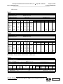
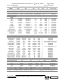
1
Test Report
Report No
Client
Address
Phone
Items tested
FCC ID
FRN
IC
EG0814-1
Summit Data Communications, Inc.
526 South Main Street Suite 411
Akron, OH 44311
330-434-7929
SDC-CFG10G
TWG-SDCCF10G
00144593390
6616A-SDCF10G
Standards
CFR 47 FCC 15.247 & RSS 210 Issue 6 Class II permissive change
Test Dates
July 31st through August 3rd of 2006
Results
As detailed within this report
Prepared by
Mairaj Hussain – Test Engineer
Authorized by
Michael Buchholz – EMC Manager
Issue Date
Conditions of Issue
8/16/06
This Test Report is issued subject to the conditions stated in the ‘Conditions of Testing’
section on page 24 of this report.
Curtis-Straus LLC is accredited to ISO/IEC 17025 by A2LA for the specific scope of accreditation under Certificate Number 1627-01. This report may
contain data which is not covered by the A2LA accreditation. See our scope of accreditation at the end of this test report. Any opinions or
interpretations expressed in this report are outside the scope of our A2LA accreditation as A2LA only accredits testing.
____________________________________________________________
Curtis-Straus • 527 Great Road • Littleton, MA • TEL (978) 486-8880 • FAX (978) 486-8828
page 1 of 28
Test Report for Summit Data Communications, Inc. • Report No. EG0814-1
August 15, 2006
FCC ID: TWG-SDCCF10G
IC ID: 6616A-SDCF10G
______________________________________________________________________
Contents
Contents .................................................................................................................................... 2
Summary ................................................................................................................................... 3
Product Tested - Configuration Documentation ........................................................................ 5
Restrictions Required for Compliance....................................................................................... 6
Test Results .............................................................................................................................. 7
802.11b.................................................................................................................................. 7
802.11g.................................................................................................................................. 9
Test Descriptions..................................................................................................................... 11
Radiated Emissions Testing Overview ................................................................................ 11
Line Conducted Emissions Overview .................................................................................. 14
Test Equipment Used.............................................................................................................. 17
Jurisdictional Labeling and Required Instruction Manual Inserts ............................................ 21
FCC Requirements .............................................................................................................. 21
Conditions Of Testing.............................................................................................................. 24
A2LA Accreditation.................................................................................................................. 26
Form Final Report REV 6-16-06 (DW)
____________________________________________________________
Curtis-Straus • 527 Great Road • Littleton, MA • TEL (978) 486-8880 • FAX (978) 486-8828
page 2 of 28
Test Report for Summit Data Communications, Inc. • Report No. EG0814-1
August 15, 2006
FCC ID: TWG-SDCCF10G
IC ID: 6616A-SDCF10G
______________________________________________________________________
Summary
This report is an application in pursuit of a class II permissive change for the radio module
MN: SDC-CF10G with FCC ID: TWG-SDCCF10G and IC ID: 6616A-SDCF10G operating in the
frequency band of 2400MHz – 2483.5MHz under FCC part 15c section 15.247 and RSS-210
Issue 6.
A Class II permissive change is requested because Summit Data Communications
wants to add two new antennas to this previously approved radio.
A brief description of antennas is given below. Detailed information regarding antennas
is available in exhibits provided with the report.
Antenna
Model Number
Manufacturer
Frequency
Gain
(GHz)
(dBi)
Radiall/Larsen
R.380.500.311
2.4 – 2.5
2
Mobil Mark
p/n: 1000159
2.4 – 2.5
5
The EUT was tested on 80 cm non-conductive foam table according to the procedures
specified in ANSI C63.4 (2003). The radio was tested with modulation on and peak and
average readings were taken. If a peak reading met the average limit, then the average
reading was not taken. Emissions from the EUT antennas were maximized around their
axis. Spurious emissions in the restricted bands were checked for both antennas.
Furthermore band edges at the restricted bands were checked.
30MHz – 25GHz
Frequency range investigated:
Measurement Distance:
Frequency (MHz)
30MHz – 18GHz
Distance (m)
3m
18GHz – 25GHz
Release Control Record
Issue No.
Reason for change
1
Original Release
0.1m
Comments
Radiated Spurious
Measurements
Radiated Spurious
Date Issued
August 15, 2006
_____________________________________________________________
Curtis-Straus • 527 Great Road • Littleton, MA • TEL (978) 486-8880 • FAX (978) 486-8828
page 3 of 28
Test Report for Summit Data Communications, Inc. • Report No. EG0814-1
August 15, 2006
FCC ID: TWG-SDCCF10G
IC ID: 6616A-SDCF10G
______________________________________________________________________
Summery of Respective Antenna Testing
Frequency
Antenna Type
(MHz)
5dBi
30 – 1000
X
1000 – 18000
X
18000 – 25000
X
2dBi
X
Band Edge
2.4GHz
2.4835GHz
2.4GHz
2.4835GHz
802.11b
X
X
X
X
802.11a
X
X
X
X
We found that two new antennas can be used with the radio modules given restrictions are met
for power settings as detailed on page 6.
The test sample was received in good condition.
_____________________________________________________________
Curtis-Straus • 527 Great Road • Littleton, MA • TEL (978) 486-8880 • FAX (978) 486-8828
page 4 of 28
Test Report for Summit Data Communications, Inc. • Report No. EG0814-1
August 15, 2006
FCC ID: TWG-SDCCF10G
IC ID: 6616A-SDCF10G
______________________________________________________________________
Product Tested - Configuration Documentation
EUT
Cable
Support Equipment
MN
SDC-CF10G
Type
UFL to SMA
UFL antenna cable
HP iPAQ
CFextender
SN
CF10G0604290001131
Length/Shielded
3 m; shielded
0.1 m; shielded
None
None
_____________________________________________________________
Curtis-Straus • 527 Great Road • Littleton, MA • TEL (978) 486-8880 • FAX (978) 486-8828
page 5 of 28
Test Report for Summit Data Communications, Inc. • Report No. EG0814-1
August 15, 2006
FCC ID: TWG-SDCCF10G
IC ID: 6616A-SDCF10G
______________________________________________________________________
Restrictions Required for Compliance
Antenna Type
5dBi
2dBi
802.11b
None
CH1 power set at 75% level
CH11 power set at 75% level
8021.g
CH1 power set at 60% level
CH11 power set at 60% level
CH1 power set at 50% level
CH11 power set at 50% level
_____________________________________________________________
Curtis-Straus • 527 Great Road • Littleton, MA • TEL (978) 486-8880 • FAX (978) 486-8828
page 6 of 28
Test Report for Summit Data Communications, Inc. • Report No. EG0814-1
August 15, 2006
FCC ID: TWG-SDCCF10G
IC ID: 6616A-SDCF10G
______________________________________________________________________
Test Results
802.11b
5dBi Antenna
Table 1
Radiated Emissions Table
Curtis-Straus LLC
Date: 01-Aug-06
Engineer: Mairaj Hussain
Company: Summit Data Communication
EUT Desc: SDC-CF1OG
Work Order: G0814
Frequency Range: 30 - 1000MHz
Notes: 5dBi antenna 802.11b
1mbps
Antenna
Measurement Distance: 3 m
RBW: 120KHz
VBW: 300KHz
Detector:
EUT Max Freq: 2460MHz
QP
FCC Class B
Preamp
Antenna
Cable
Adjusted
Polarization
Frequency
Reading
Factor
Factor
Factor
Reading
Limit
Margin
Result
(H / V)
(MHz)
(dBµV)
(dB)
(dB/m)
(dB)
(dBµV/m)
(dBµV/m)
(dB)
(Pass/Fail)
v
v
v
v
v
v
v
v
v
v
h
h
h
37.58
74.16
116.8
131.0
149.95
156.86
163.96
165.66
168.1
171.22
247.43
328.9
405.96
29.0
51.3
35.0
39.0
33.0
40.6
44.8
47.2
51.2
50.6
42.4
42.5
33.0
26.2
26.2
26.2
26.2
26.1
26.1
26.1
26.1
26.2
26.2
26.1
26.1
26.0
16.5
8.7
13.4
14.6
13.0
12.8
12.6
12.5
12.4
12.1
12.3
14.6
16.2
0.8
1.2
1.5
1.6
1.7
1.8
1.7
1.7
1.8
1.8
2.1
2.5
3.0
20.1
35.0
23.7
29.0
21.6
29.1
33.0
35.3
39.2
38.3
30.7
33.5
26.2
40.0
40.0
43.5
43.5
43.5
43.5
43.5
43.5
43.5
43.5
46.0
46.0
46.0
-19.9
-5.0
-19.8
-14.5
-21.9
-14.4
-10.5
-8.2
-4.3
-5.2
-15.3
-12.5
-19.8
Pass
Pass
Pass
Pass
Pass
Pass
Pass
Pass
Pass
Pass
Pass
Pass
Pass
Test Site: "F"
Pre-Amp: Orange
Cable: EMIR-03
Analyzer: Green
Antenna: Red-Black
Table 2
Spurious and Band Edge
Curtis-Straus LLC
Date: 31-Jul-06
Engineer: Mairaj Hussain
Company: Summit Data Communications
EUT Desc: SDC-CF/10G
Work Order: G0814
Frequency Range: 1 - 18GHz
Notes: 802.11b
5dBi Antenna
Measurement Distance: 3 m
EUT Max Freq: 2460MHz
RBW:
1MHz
VBW: 1MHz & 30Hz
Antenna
---
FCC Class B
Preamp
Antenna
Cable
Adjusted
Polarization
Frequency
Reading
Factor
Factor
Factor
Reading
Limit
Margin
Result
Limit
Margin
Result
(H / V)
(MHz)
(dBµV)
(dB)
(dB/m)
(dB)
(dBµV/m)
(dBµV/m)
(dB)
(Pass/Fail)
(dBµV/m)
(dB)
(Pass/Fail)
Vpk
Vavg
300KHZ RBW
Vpk
Vbe
Delta:
PK @ BE
Avg @ BE
Vpk
Vavg
Vpk
Upper Band Edge
Vpk
Vavg
300KHZ RBW
Vpk
Vbe
Delta:
PK @ BE
Avg @ BE
2409.0
2409.0
116.8
114.1
39.3
39.3
29.8
29.8
2.5
2.5
109.8
107.1
2409.0
2390.0
39.3
39.4
29.8
29.7
2.5
2.5
107.0
53.4
2390.0
2390.0
4820.0
4820.0
7235.0
114.0
60.6
53.4
63.4
60.7
54.0
51.6
48.0
39.4
39.4
39.3
39.3
39.1
29.7
29.7
35.3
35.3
38.2
2.5
2.5
3.8
3.8
4.8
56.2
53.5
53.8
51.4
51.9
74.0
54.0
74.0
54.0
54.0
-17.8
-0.5
-20.2
-2.6
-2.1
Pass
Pass
Pass
Pass
Pass
2460.0
2460.0
117.0
109.0
39.7
39.7
29.9
29.9
2.6
2.6
109.8
101.8
2460.0
2483.5
114.7
64.0
50.7
66.3
58.3
39.7
39.0
29.9
30.0
2.6
2.6
107.5
57.6
39.0
39.0
30.0
30.0
2.6
2.6
59.9
51.9
74.0
54.0
-14.1
-2.1
Pass
Pass
Test Site: F
2483.5
2483.5
Pre-Amp: Brown/HF
Cable: EMIR-HIGH 10
Analyzer: Brown
Antenna: Orange Horn/HF
Note: No emissions found 18-25GHz range.
_____________________________________________________________
Curtis-Straus • 527 Great Road • Littleton, MA • TEL (978) 486-8880 • FAX (978) 486-8828
page 7 of 28
Test Report for Summit Data Communications, Inc. • Report No. EG0814-1
August 15, 2006
FCC ID: TWG-SDCCF10G
IC ID: 6616A-SDCF10G
______________________________________________________________________
2dBi Antenna
Table 3
Band Edge
Curtis-Straus LLC
Date: 03-Aug-06
Engineer: Mairaj Hussain
Company: Summit Data Communications
EUT Desc: SDC-CG10G
Work Order: G0814
Frequency Range:
Measurement Distance: 3 m
Notes: 802.11b;
2dBi antenna
EUT Max Freq: 2460
RBW: 1MHz
VBW: 1MHz & 30Hz
Antenna
---
FCC Class B
Preamp
Antenna
Cable
Adjusted
Polarization
Frequency
Reading
Factor
Factor
Factor
Reading
Limit
Margin
Result
Limit
Margin
Result
(H / V)
(MHz)
(dBµV)
(dB)
(dB/m)
(dB)
(dBµV/m)
(dBµV/m)
(dB)
(Pass/Fail)
(dBµV/m)
(dB)
(Pass/Fail)
2409.0
2409.0
115.2
113.5
39.3
39.3
29.8
29.8
2.5
2.5
108.2
106.5
113.2
39.3
58.0
39.4
55.2
60.0
39.4
58.3
39.4
Pre-Amp: Brown
29.8
29.7
2.5
2.5
106.2
50.8
Set power 75%
Hpk
Havg
300KHz RBW
Hpk
Hbe
Delta:
Pk @ BE
Avg @ BE
2409.0
2389.1
2390.0
2390.0
Test Site: "F"
29.7
2.5
52.8
29.7
2.5
51.1
Cable: EMIR-HIGH 10
74.0
-21.2
54.0
-2.9
Antenna: Orange Horn
Analyzer: Brown
Table 4
Radiated Emissions Table
Pass
Pass
Curtis-Straus LLC
Date: 03-Aug-06
Engineer: Mairaj Hussain
Company: Summit Data Communications
EUT Desc: SDC-CG10G
Work Order: G0814
Measurement Distance: 3 m
Notes: 802.11b; Power set 75%
2dBi antenna
Antenna
EUT Max Freq: 2460
RBW: 1MHz
VBW: 1MHz & 30Hz
---
FCC Class B
Preamp
Antenna
Cable
Adjusted
Polarization
Frequency
Reading
Factor
Factor
Factor
Reading
Limit
Margin
Result
Limit
Margin
Result
(H / V)
(MHz)
(dBµV)
(dB)
(dB/m)
(dB)
(dBµV/m)
(dBµV/m)
(dB)
(Pass/Fail)
(dBµV/m)
(dB)
(Pass/Fail)
2464.0
2464.0
116.0
113.5
39.7
39.7
29.9
29.9
2.6
2.6
108.8
106.3
2464.0
2487.9
113.2
58.2
55.0
61.0
58.5
39.7
39.0
29.9
30.0
2.6
2.6
106.0
51.8
39.0
39.0
30.0
30.0
2.6
2.6
54.6
52.1
74.0
54.0
-19.4
-1.9
Pass
Pass
802.11b; CH1
Hpk
Havg
300KHz RBW
Hpk
Hbe
Delta:
Pk @ BE
Avg @ BE
Test Site: "F"
2483.5
2483.5
Pre-Amp: Brown
Cable: EMIR-HIGH 10
Analyzer: Brown
Antenna: Orange Horn
Restriction: Power set at 75% level for CH1 & CH11.
_____________________________________________________________
Curtis-Straus • 527 Great Road • Littleton, MA • TEL (978) 486-8880 • FAX (978) 486-8828
page 8 of 28
Test Report for Summit Data Communications, Inc. • Report No. EG0814-1
August 15, 2006
FCC ID: TWG-SDCCF10G
IC ID: 6616A-SDCF10G
______________________________________________________________________
802.11g
5dBi Antenna
Table 5
Band Edge
Curtis-Straus LLC
Date: 03-Aug-06
Engineer: Mairaj Hussain
Company: Summit Data Communications
EUT Desc: SDC-CG10G
Work Order: G0814
Measurement Distance: 3 m
Notes:
EUT Max Freq: 2460
RWB:
1MHz
VBW: 1MHz & 30Hz
5dBi antenna
Antenna
---
FCC Class B
Preamp
Antenna
Cable
Adjusted
Polarization
Frequency
Reading
Factor
Factor
Factor
Reading
Limit
Margin
Result
Limit
Margin
Result
(H / V)
(MHz)
(dBµV)
(dB)
(dB/m)
(dB)
(dBµV/m)
(dBµV/m)
(dB)
(Pass/Fail)
(dBµV/m)
(dB)
(Pass/Fail)
114.0
107.0
39.3
39.4
29.8
29.8
2.5
2.5
107.0
99.9
110.6
39.3
62.0
39.4
48.6
65.4
39.4
58.4
39.4
Pre-Amp: Brown
29.8
29.7
2.5
2.5
103.6
54.8
Set power to 60% at CH1
2407.0
2412.0
Vpk
Vavg
300KHZ RBW
Vpk
Vbe
Delta:
PK @ BE
Avg @ BE
2407.0
2390.0
2390.0
2390.0
Test Site: "F"
29.7
2.5
58.2
29.7
2.5
51.2
Cable: EMIR-HIGH 10
74.0
-15.8
54.0
-2.8
Antenna: Orange Horn
Analyzer: Brown
Pass
Pass
Restriction: CH1 power set at 60%
Table 6
Upper Band Edge
Curtis-Straus LLC
Date: 03-Aug-06
Engineer: Mairaj Hussain
Company: Summit Data Communications
EUT Desc: SDC-CG10G
Work Order: G0814
Measurement Distance: 3 m
Notes:
EUT Max Freq: 2460
RWB:
1MHz
VBW: 1MHz & 30Hz
5dBi antenna
Antenna
---
FCC Class B
Preamp
Antenna
Cable
Adjusted
Polarization
Frequency
Reading
Factor
Factor
Factor
Reading
Limit
Margin
Result
Limit
Margin
Result
(H / V)
(MHz)
(dBµV)
(dB)
(dB/m)
(dB)
(dBµV/m)
(dBµV/m)
(dB)
(Pass/Fail)
(dBµV/m)
(dB)
(Pass/Fail)
2457.6
2456.0
114.1
105.0
39.7
39.7
29.9
29.9
2.6
2.6
106.9
97.8
2466.1
2483.5
110.0
60.0
50.0
64.1
55.0
39.6
39.0
29.9
30.0
2.6
2.6
102.9
53.6
39.0
39.0
30.0
30.0
2.6
2.6
57.7
48.6
74.0
54.0
-16.3
-5.4
Pass
Pass
Power set 60%
Vpk
Vavg
300KHz RBW
Vpk
Vbe
Delta:
Pk @ BE
Avg @ BE
Test Site: "F"
2483.5
2483.5
Pre-Amp: Brown
Cable: EMIR-HIGH 10
Analyzer: Brown
Antenna: Orange Horn
Restriction: CH11 power set at 60%
_____________________________________________________________
Curtis-Straus • 527 Great Road • Littleton, MA • TEL (978) 486-8880 • FAX (978) 486-8828
page 9 of 28
Test Report for Summit Data Communications, Inc. • Report No. EG0814-1
August 15, 2006
FCC ID: TWG-SDCCF10G
IC ID: 6616A-SDCF10G
______________________________________________________________________
2dBi Antenna
Table 7
Lower Band Edge
Curtis-Straus LLC
Date: 03-Aug-06
Engineer: Mairaj Hussain
Company: Summit Data Communications
EUT Desc: SDC-CG10G
Work Order: G0814
Measurement Distance: 3 m
Notes: Power set 50%
2dBi antenna
EUT Max Freq: 2460
RWB: 1MHz
VBW: 1MHz & 30Hz
Antenna
---
FCC Class B
Preamp
Antenna
Cable
Adjusted
Polarization
Frequency
Reading
Factor
Factor
Factor
Reading
Limit
Margin
Result
Limit
Margin
Result
(H / V)
(MHz)
(dBµV)
(dB)
(dB/m)
(dB)
(dBµV/m)
(dBµV/m)
(dB)
(Pass/Fail)
(dBµV/m)
(dB)
(Pass/Fail)
2407.0
2407.0
114.8
108.0
--39.3
39.3
--39.3
39.4
--29.8
29.8
--29.8
29.7
--2.5
2.5
--2.5
2.5
--107.8
101.0
--103.7
56.0
802.11g; CH1
Hpk
Havg
300KHz RBW
Hpk
Hbe
Delta:
Pk @ BE
Avg @ BE
2407.0
2390.0
110.7
63.2
47.5
67.3
39.4
60.5
39.4
Pre-Amp: Brown
2390.0
2390.0
Test Site: "F"
29.7
2.5
60.1
29.7
2.5
53.3
Cable: EMIR-HIGH 10
74.0
-13.9
54.0
-0.7
Antenna: Orange Horn
Analyzer: Brown
Table 8
Upper Band Edge
Pass
Pass
Curtis-Straus LLC
Date: 03-Aug-06
Engineer: Mairaj Hussain
Company: Summit Data Communications
EUT Desc: SDC-CG10G
Work Order: G0814
Measurement Distance: 3 m
Notes:
EUT Max Freq: 2460
RWB: 1MHz
VBW: 1MHz & 30Hz
2dBi antenna
Antenna
---
FCC Class B
Preamp
Antenna
Cable
Adjusted
Polarization
Frequency
Reading
Factor
Factor
Factor
Reading
Limit
Margin
Result
Limit
Margin
Result
(H / V)
(MHz)
(dBµV)
(dB)
(dB/m)
(dB)
(dBµV/m)
(dBµV/m)
(dB)
(Pass/Fail)
(dBµV/m)
(dB)
(Pass/Fail)
2463.9
2464.0
114.0
106.0
39.7
39.7
29.9
29.9
2.6
2.6
106.8
98.8
110.0
39.6
61.8
39.0
48.2
65.8
39.0
57.8
39.0
Pre-Amp: Brown
29.9
30.0
2.6
2.6
102.9
55.4
Power set 50%
Hpk
Havg
300KHz RBW
Hpk
Hbe
Delta:
Pk @ BE
Avg @ BE
2466.1
2483.5
2483.5
2483.5
Test Site: "F"
30.0
2.6
59.4
30.0
2.6
51.4
Cable: EMIR-HIGH 10
74.0
-14.6
54.0
-2.6
Antenna: Orange Horn
Analyzer: Brown
Pass
Pass
Restriction: Power set for CH1 & CH11 at 50% level
Table 9
Spurious Emissions
Curtis-Straus LLC
Date: 03-Aug-06
Engineer: Mairaj Hussain
Company: Summit Data Communications
EUT Desc: SDC-CG10G
Work Order: G0814
Frequency Range: 1 - 18GHz Restricted Band
Notes:
2dBi antenna
Antenna
Polarization
(H / V)
Frequency
(MHz)
802.11b & g
Hpk
4924.3
Table Result:
Test Site: "F"
Measurement Distance: 3 m
VBW: 1MHz
RBW:1MHz
EUT Max Freq: 2460
Preamp
Antenna
Cable
Adjusted
Reading
(dBµV)
Factor
(dB)
Factor
(dB/m)
Factor
(dB)
Reading
(dBµV/m)
51.0
39.0
35.6
3.8
51.4
Pass
by
Pre-Amp: Brown
---
54.0
-2.6 dB
Cable: EMIR-HIGH 10
FCC Class B
Limit
(dBµV/m)
Worst Freq:
Analyzer: Brown
Margin
(dB)
Result
(Pass/Fail)
-2.6
Pass
4924.3 MHz
Antenna: Orange Horn
_____________________________________________________________
Curtis-Straus • 527 Great Road • Littleton, MA • TEL (978) 486-8880 • FAX (978) 486-8828
page 10 of 28
Test Report for Summit Data Communications, Inc. • Report No. EG0814-1
August 15, 2006
FCC ID: TWG-SDCCF10G
IC ID: 6616A-SDCF10G
______________________________________________________________________
Test Descriptions
Radiated Emissions Testing Overview
REV 22-SEP-05
Digital and microprocessor based devices use radio frequency (RF) digital signals for
timing purposes. An unintentional consequence of this signal usage is that a certain amount of
RF energy is radiated from the device into the local environment. This radiated RF energy has
the potential to interfere with constructive uses of the RF spectrum such as television
broadcasting, police and fire radio, and the like. In order to reduce the likelihood that a device
will interfere with these services, it is required that the amplitudes of radiated RF signals from
the device are kept below an allowable level.
These RF signals decrease in strength as the distance from the source increases. Thus
if the potential victim of interference, e.g. a TV receiver, is far enough from the radiator, e.g. a
computer, then no interference will occur. For certain environments it is appropriate to expect
that potential interference victims will be located at least a minimum distance from the radiator.
For the residential environment this distance is generally accepted to be 10 meters while in the
commercial environment the accepted distance is 30 meters. The allowable emissions levels
are therefore specified to protect equipment which is located further than that distance from the
radiator. In general, radiation from the Equipment Under Test (EUT) is measured at 3 or 10
meters to insure that it is at or below allowable levels.
Measurements of the radiated energy are made by recording the field strength indicated
by an antenna placed at a specific distance from the device. Most devices do not radiate the RF
energy in a predictable manner. The emitted energy may vary with changes in operating mode,
physical configuration, or orientation. During the measurement process these parameters are
varied to confirm that the emissions will remain below the allowable levels in the range of typical
installations.
The extent of annoyance experienced by a person who is being affected by interference
is related to the persistence of the interfering signal. For example, a low level steady whine from
a receiver is considered to be more annoying than brief, loud, intermittent pops or clicks. This
“human factor” is accounted for by the use of a “quasi-peak” detector in the receiver or spectrum
analyzer which measures the signal from the measurement antenna. The detector is a weighted
averaging filter with a fast charge time and a slow discharge time. Thus steady continuous
signals will charge the quasi-peak detector fully while intermittent signals (those with pulse
repetition rates less than 1kHz) are reported at a level which can be significantly below their
peak level. It should be noted that most RF signals produced by digital devices are continuous
in nature and thus the quasi-peak reading will be identical to the peak signal reading. To reduce
the test time, the peak emission level is recorded for continuous wave signals as it is the same
as the quasi-peak signal level.
Testing is performed according to test methods from ANSI C63.4 and CISPR 22.
The test site used for measuring radiated emissions follows the format developed
internationally for a weather protected Open Area Test Site (OATS). An antenna mast is
_____________________________________________________________
Curtis-Straus • 527 Great Road • Littleton, MA • TEL (978) 486-8880 • FAX (978) 486-8828
page 11 of 28
Test Report for Summit Data Communications, Inc. • Report No. EG0814-1
August 15, 2006
FCC ID: TWG-SDCCF10G
IC ID: 6616A-SDCF10G
______________________________________________________________________
installed at the specified distance from a rotating table and is used to raise and lower the
measuring antenna. The reference site is clear of reflecting objects, such as metal fences and
buildings for an ellipse of twice the measurement test distance. Measuring equipment and
personnel are present within the ellipse to facilitate cable manipulation, but measures are taken
to minimize the effects. Often preliminary radiated emissions measurements are made at
alternate test sites which do not meet the clear space reference criteria. The data collected at
alternate test sites is not considered conclusive unless the alternate site also complies with a
volumetric site attenuation survey performed over the area that the EUT occupies. The EUT and
measuring antenna mark the two foci of the ellipse. The ground plane is made of a combination
of galvanized steel sheets and tight wire mesh electrically connected along the seams. This
metal ground plane extends 1 meter beyond the furthest extent of the EUT and the measuring
antenna. It also covers the area between the EUT and the measuring antenna. The hardware
cloth is connected to the utility ground or to stakes driven into the earth for safety.
In order for accurate emissions measurements to be made the test site must possess
propagation characteristics which fall within accepted norms. The site has been checked for
suitability using techniques specified in American National Standards Institute (ANSI) document
C63.4. This document details a procedure which measures the attenuation of the site which is
the chief indicator of site acceptability. The theory behind site attenuation is quite simple. A
transmitting antenna is set up at a fixed location at one end of the site with a receiving antenna
at the other end. If a signal of some arbitrary amplitude is fed into the transmitting antenna, a
lesser amount of signal ought to be measured at the receiving antenna. This difference in signal
amplitude is known as the site attenuation, which should follow a predicted curve. Data that
does not correspond to the predicted site attenuation curve points to a problem with either the
equipment being used or the physical characteristics of the site.
Actual emissions measurements are taken with broadband biconical-log-periodic hybrid
antennas calibrated in accordance with the standard site method detailed in ANSI C63.5.
Emissions are measured with the receiving antenna oriented in horizontal and vertical
polarization with respect to the ground plane. If measurements are made at other than the limit
distance, then the readings obtained are scaled to the limit distance using an inverse
relationship. The actual test distance used is noted in the report.
The antenna mast is capable of a varying the antenna height between 1 and 4 meters
above the ground plane. The receiving antenna is moved over this range at each emission
frequency in order to record the maximum observed signal. The mast is non-conductive and
remotely controllable. The test distance is measured from the antenna center (marked during
calibration) and the periphery of the EUT.
The Equipment Under Test (EUT) is rotated in order to maximize emissions during the
test. For equipment intended to operate on a tabletop or desk radiated tests are conducted on a
0.8 meter high, non-conductive platform. Larger floor standing equipment is tested on a floor
mounted rotatable platform. In some cases, large equipment on its own casters may be tested
without a platform.
Since radiated emissions are a function of cable placement, the cable placement is
varied to encompass typical configurations that an end user might encounter to determine the
configuration resulting in maximum emissions. At least one cable for each I/O port type is
_____________________________________________________________
Curtis-Straus • 527 Great Road • Littleton, MA • TEL (978) 486-8880 • FAX (978) 486-8828
page 12 of 28
Test Report for Summit Data Communications, Inc. • Report No. EG0814-1
August 15, 2006
FCC ID: TWG-SDCCF10G
IC ID: 6616A-SDCF10G
______________________________________________________________________
attached to the EUT. If peripherals or modules are available, at least one of each available type
is installed and noted in the report. Excess cable length beyond one meter is bundled in the
center into a 30 to 40 cm bundle. Cables requiring non-standard lead dress are recorded in the
report.
Network connections are simulated if necessary. Any simulator used matches the
expected real network connection in terms of both functionality and impedance. For distributed
systems, the support equipment may be placed at such a distance that it does not influence the
measured emissions. If this option is used, such placement is noted in the test report.
The possible operating modes of the EUT are explored to determine the configuration
which maximizes emissions. Software is investigated as well as different methods of displaying
data if available. Data is recorded in the worst case operating mode.
At least the six highest emissions with respect to the limit are recorded. If less than six
emissions are visible above the noise floor of the instrumentation, then noise floor
measurements at six representative frequencies are recorded. The test report will document if
noise floor readings are reported.
FCC and European Norms Radiated Emissions Limits at 10 meters
Frequency (MHz)
30-88
88-216
216-230
230-960
960-1000
1000+
FCC Class A
39.1
43.5
46.4
46.4
49.5
49.5
FCC Class B
29.5
33.1
35.6
35.6
43.5
43.5
CISPR Class A
40
40
40
47
47
N/A
CISPR Class B
30
30
30
37
37
N/A
Frequency (MHz)
30-88
88-216
216-230
230-960
960-1000
1000+
At the transitions, the lower limit applies.
Simple inverse scaling utilized to convert limits where appropriate.
FCC and European Norms Radiated Emissions Limits at 3 meters
Frequency (MHz)
30-88
88-216
216-230
230-960
960-1000
1000+
FCC Class A
49.5
54
56.9
56.9
60
60
FCC Class B
40
43.5
46
46
54
54
CISPR Class A
50.5
50.5
50.5
57.5
57.5
N/A
CISPR Class B
40.5
40.5
40.5
47.5
47.5
N/A
Frequency (MHz)
30-88
88-216
216-230
230-960
960-1000
1000+
At the transitions, the lower limit applies.
Simple inverse scaling utilized to convert limits where appropriate.
_____________________________________________________________
Curtis-Straus • 527 Great Road • Littleton, MA • TEL (978) 486-8880 • FAX (978) 486-8828
page 13 of 28
Test Report for Summit Data Communications, Inc. • Report No. EG0814-1
August 15, 2006
FCC ID: TWG-SDCCF10G
IC ID: 6616A-SDCF10G
______________________________________________________________________
For CISPR and EU standards measurements are usually made over the frequency
range of 30 MHz to 1GHz. Deviations are noted in the test report. For the FCC, the
measurement range is based on the highest frequency signal present or used in the device.
The following table details the frequency range of measurements performed.
FCC frequency range of radiated emissions measurements
Highest frequency generated or used in the
device or on which the device operates or
tunes (MHz)
Below 1.705
1.705-108
108-500
500-1000
Above 1000
Upper frequency of measurement
range (MHz)
30 (No radiated measurements)
1000
2000
5000
5th harmonic of the highest frequency
or 40 GHz, whichever is lower.
The test data is derived from the voltage on the spectrum analyzer. First the reading is
corrected for gain factors associated with the use of preamps and loss in the cable. A factor in
dB is subtracted from the reading to account for preamp gain, while a factor in dB is added to
the signal to account for cable loss. A conversion is performed from the resulting voltage to field
strength by multiplying the voltage by the antenna factor. Since antenna factor is expressed as
a logarithm (dB/m), this operation takes the form of an addition (to multiply logarithmic numbers,
you add them together). Thus:
Field Strength (dBuV/m) = Voltage Reading (dBuV) - Preamp Gain (dB) + Cable Loss (dB) + Antenna Factor (dB/m)
When the levels of ambient radio signals such as local television stations are within 6 dB
of the appropriate limit, the following steps may be taken to assure compliance:
1. The measurement bandwidth may be reduced. A check is made to see that peak
readings are not affected. The use of a narrower bandwidth allows examination of
emissions close to local ambient signals.
2. The antenna may be brought closer to the EUT to increase signal-to-ambient signal
strength.
3. For horizontally polarized signals the axis of the test site may be rotated to
discriminate against local ambients.
Standard Uncertainty per NIST Technical Note 1297 1994 for this test is estimated to be
2.8dB. This test method is covered by our A2LA accreditation.
Line Conducted Emissions Overview
REV 9-MAY-06
Digital and microprocessor based devices use radio frequency (RF) digital techniques
for timing purposes and in applications such as switching power supplies. An unintentional
consequence of this for AC powered devices is that a certain amount of the RF energy is
impressed upon the AC power mains in the form of a conducted noise voltage. These
_____________________________________________________________
Curtis-Straus • 527 Great Road • Littleton, MA • TEL (978) 486-8880 • FAX (978) 486-8828
page 14 of 28
Test Report for Summit Data Communications, Inc. • Report No. EG0814-1
August 15, 2006
FCC ID: TWG-SDCCF10G
IC ID: 6616A-SDCF10G
______________________________________________________________________
conducted emissions have the potential to interfere with constructive uses of the RF spectrum
such as AM radio and may also interfere with other devices attached to the same AC mains
circuit. In order to reduce the likelihood that a device will interfere it is required that the
conducted RF signals from the device are below an allowable level.
Testing is performed according to test methods from ANSI C63.4 and CISPR 22.
Line conducted emissions are measured from the device over the frequency range of
0.15 to 30 MHz. The EUT is powered from a Line Impedance Stabilization Network (LISN). The
purpose of the LISN is to provide a calibrated impedance across which to measure the
conducted emissions. The RF noise voltage produced by the EUT across the LISN is measured
and compared to the limit. In order for the LISN to perform properly it is attached to a ground
plane at least 2 meters by 2 meters in size. For tabletop equipment the measurement is
performed with the equipment 40 cm from a vertical conducting surface bonded to a ground
plane under the product. The ground plane extends 0.5 meters beyond the product and is
2.5mx3.7m in size. The vertical surface is 2.5mx2.5m.
As with radiated emissions, the “human factor” is accounted for by the use of a “quasipeak” detector in the receiver or spectrum analyzer that measures the signal from the LISN. For
certain tests (such as EN55022), both an average and a quasi-peak limit are specified.
Emissions from a device must be below both limits when measured with the appropriate
detector. If the emission level is below the average limit when measured with the quasi-peak
detector, the EUT is presumed to pass both limits.
The possible operating modes of the EUT are explored to determine the configuration that
maximizes emissions. Software is investigated as well as different methods of displaying data if
available. Data is recorded in the worst case operating mode.
As of September 9, 2002, the FCC has harmonized it’s conducted emission limits with
CISPR. The following table displays the limits applicable to both FCC and CISPR.
Line Conducted Emissions Limits: Class A (dBµV)
Frequency (MHz)
0.15 - 0.5
0.5 - 30
Quasi-Peak
79
73
Average
66
60
Line Conducted Emissions Limits: Class B (dBµV)
Frequency (MHz)
0.15 - 0.5
0.5 - 5
5 - 30
Quasi-Peak
66 - 56*
56
60
Average
56 - 46*
46
50
Note 1: The lower limit applies at the transition frequencies
*Note 2: The limit decreases linearly with the logarithm of the frequency
At least the six highest emissions with respect to the limit are recorded. If less than six
emissions are visible above the noise floor of the instrumentation, then the noise floor at six
representative frequencies is recorded. The test report will document if noise floor readings are
reported.
_____________________________________________________________
Curtis-Straus • 527 Great Road • Littleton, MA • TEL (978) 486-8880 • FAX (978) 486-8828
page 15 of 28
Test Report for Summit Data Communications, Inc. • Report No. EG0814-1
August 15, 2006
FCC ID: TWG-SDCCF10G
IC ID: 6616A-SDCF10G
______________________________________________________________________
Standard Uncertainty per NIST Technical Note 1297 1994 for this test is estimated to be
2dB.
All testing is performed within the framework of a laboratory quality system modeled on
ISO/IEC 17025 General requirements for the competence of calibration and testing laboratories
and is subject to our terms and conditions. This test method is covered by our A2LA
accreditation.
_____________________________________________________________
Curtis-Straus • 527 Great Road • Littleton, MA • TEL (978) 486-8880 • FAX (978) 486-8828
page 16 of 28
Test Report for Summit Data Communications, Inc. • Report No. EG0814-1
August 15, 2006
FCC ID: TWG-SDCCF10G
IC ID: 6616A-SDCF10G
______________________________________________________________________
Test Equipment Used
REV. 28-JUL-2006
SPECTRUM ANALYZERS /
RECEIVERS
RED
WHITE
BLUE
YELLOW
GREEN
BLACK
TELECOM 3585A
TELECOM 3585A
TELECOM 3585A
ORANGE
BROWN (RENTAL)
EMI TEST RECEIVER
LISNS/MEASUREMENT
PROBES
RED
BLUE (DC)
YELLOW-BLACK
ORANGE
GOLD (DC)
BROWN
GREEN
YELLOW
WHITE-BLACK
BLACK
RED-BLACK
BLUE-BLACK
BLUE MONITORING PROBE
YELLOW MONITORING PROBE
GREEN CURRENT TRANSFORMER
BLUE CISPR LINE PROBE
BLACK CISPR LINE PROBE
CISPR TELCO VOLTAGE PROBE
CISPR 22 TELCO ISN
RANGE
MN
MFR
SN
ASSET
CAT
CALIBRATION DUE
9kHz-1.8GHz
9kHz-22GHz
9kHz-1.8GHz
9kHz-2.9GHz
9kHz-26.5GHz
9kHz-12.8GHz
20Hz-40.0MHz
20Hz-40.0MHz
20Hz-40.0MHz
9kHz-26.5GHz
9kHz-26.5GHz
20-1000MHz
8591E
8593E
8591E
8594E
8593E
8596E
3585A
3585A
3585A
E4407B
E4407B
ESVS30
HP
HP
HP
HP
HP
HP
HP
HP
HP
HP
HP
R&S
3441A03559
3547U01252
3223A00227
3523A01958
3829A03618
3710A00944
2504A05219
1750A03418
1750A02762
US39440975
SG44210511
827957/001
00024
00022
00070
00100
00143
00337
00030
00558
01067
00394
Rental
01098
I
I
I
I
I
I
I
1
I
I
1
I
30-DEC-2006
14-MAR-2007
14-DEC-2006
05-JUN-2007
21-NOV-2006
02-NOV-2006
07-FEB-2007
23-MAY-2007
01-MAR-2007
Out of Service
05-JAN-2007
27-OCT-2006
RANGE
MN
MFR
SN
ASSET
CAT
CALIBRATION DUE
10KHZ-30MHZ
10KHZ-30MHZ
10KHZ-30MHZ
10KHZ-30MHZ
10KHZ-30MHZ
10KHZ-30MHZ
10KHZ-30MHZ
10KHZ-30MHZ
10KHZ-30MHZ
10KHZ-30MHZ
10KHZ-30MHZ
10KHZ-30MHZ
0.01-150MHZ
0.01-150MHZ
40HZ-20MHZ
150KHZ-30MHZ
150KHZ-30MHZ
10KHZ-30MHZ
9KHZ-30MHZ
8012-50-R-24-BNC
8012-50-R-24-BNC
8012-50-R-24-BNC
8012-50-R-24-BNC
8012-50-R-24-BNC
8012-50-R-24-BNC
8012-50-R-24-BNC
8012-50-R-24-BNC
8610-50-TS-100-N
8610-50-TS-100-N
8610-50-TS-100-N
8610-50-TS-100-N
91550-2
91550-2
150
N/A
N/A
CS A/C-10
FCC-TLISN-T4
SOLAR
SOLAR
SOLAR
SOLAR
SOLAR
SOLAR
SOLAR
SOLAR
SOLAR
SOLAR
SOLAR
SOLAR
TEGAM
ETS
PEARSON
C-S
C-S
C-S
FISCHER
956348
956349
984735
903707
984734
0411656
0411657
0411658
972019
972017
972016
972018
12350
50972
10226
N/A
N/A
CS01
20115
00753
00752
00248
00754
00247
00986
00987
1080
00678
00675
00677
00676
00807
00493
00793
00805
II
II
II
II
II
II
II
II
II
II
II
II
I
I
I
II
II
II
I
05-MAY-2007
05-MAY-2007
05-MAY-2007
05-MAY-2007
05-MAY-2007
05-MAY-2007
08-MAY-2007
05-MAY-2007
05-MAY-2007
05-MAY-2007
05-MAY-2007
05-MAY-2007
26-MAY-2007
23-JAN-2008
07-APR-2007
08-JUN-2007
08-JUN-2007
30-SEP-2006
26-OCT-2006
OPEN AREA TEST SITE (OATS)
SITE F
SITE T
SITE A
SITE M
SITE J
LINE CONDUCTED TEST SITES
EMI 1
EMI 2
EMI 3
MIXERS/DIPLEXERS
MIXER / HORN
MIXER / HORN
MIXER / HORN
MIXER
MIXER / HORN
MIXER
MIXER / HORN
MIXER / HORN
MIXER / HORN
DIPLEXER
RANGE
26.5-40 GHZ
26.5-40 GHZ
40-60 GHZ
33-50 GHZ
50-75 GHZ
75-110 GHZ
60-90 GHZ
90-140 GHZ
140-220 GHZ
40-220 GHZ
FCC CODE
93448
93448
93448
93448
93448
IC CODE
IC 2762-F
IC 2762-T
IC 2762-A
IC 2762-M
IC 2762A-10
FCC CODE
93448
93448
93448
IC CODE
N/A
N/A
N/A
MN
11970A/28-442-6
11970A/28-442-6
M19HW/A
11970Q
MFR
HP/ATM
HP/ATM
OML
HP
11970V /QWH-VPRROO
HP/QUINSTAR
11970W
M12HW/A
MO8HW/A
MO5HW/A
DPL.26
HP
OML
OML
OML
OML
NONE
00296
00746
VCCI CODE
R-1688
R-905
R-903
R-904
CAT
II
II
II
II
II
VCCI CODE
C-1801
C-1802
C-1803
SN
2332A01695/A046903-01
3003A07825/A046903-01
U30110-1
3003A03155
2521A01197/8794001
2521A01334
E30110-1
F21206-1
G21206-1
N/A
ASSET
1087
1086
00821
00104
1179
00105
00822
00811
00812
00813
CALIBRATION DUE
04-APR-2007
14-AUG-2007
13-AUG-2007
19-MAR-2007
11-APR-2008
CAT
III
III
III
CALIBRATION DUE
NA
NA
NA
CAT
I
I
I
I
I
I
I
I
II
I
CALIBRATION DUE
23-AUG-2006
23-AUG-2006
02-MAR-2007
08-NOV-2007
15-NOV-2007
22-NOV-2007
03-MAR-2007
03-MAR-2007
03-MAR-2007
_____________________________________________________________
Curtis-Straus • 527 Great Road • Littleton, MA • TEL (978) 486-8880 • FAX (978) 486-8828
page 17 of 28
Test Report for Summit Data Communications, Inc. • Report No. EG0814-1
August 15, 2006
FCC ID: TWG-SDCCF10G
IC ID: 6616A-SDCF10G
______________________________________________________________________
ABSORBING
CLAMPS
RANGE
MN
MFR
SN
ASSET
CAT
CALIBRATION DUE
FISCHER CLAMP
30-1000MHZ
F-201-23MM
FISCHER
10
00081
I
20-JAN-2008
MN
HP6842A
(2) 500I
HARMONIC & FLICKER ANALYZER
HFTS
10001I/2 AC POWER SYSTEM
PREAMPS / ATTENUATORS /
FILTERS
RED
BLUE
BLUE-BLACK
GREEN
BLACK
ORANGE
WHITE
BROWN
YELLOW-BLACK
RED-GREEN
HF (YELLOW)
HIGH PASS FILTER
LOW PASS FILTER
HF 20DB 50W ATTENUATOR
HF 30DB 50W ATTENUATOR
LOW FREQ LPF
LOW FREQ LPF
MFR
SN
ASSET
CAT
CALIBRATION DUE
C-S
C-S
C-S
C-S
C-S
C-S
C-S
C-S
C-S
C-S
C-S
N/A
N/A
N/A
N/A
N/A
N/A
426643
PL1655
535055
00798
00759
00800
00802
00799
00765
00760
1132
00801
467559
36
4
01
02
00758
00817
00816
00791
1168
1019
1088
II
II
II
II
II
II
II
II
II
II
II
II
II
II
II
II
II
28-JUL-2007
20-JUL-2007
04-JAN-2007
20-JUL-2007
20-JUL-2007
28-DEC-2006
22-JUL-2007
14-APR-2007
22-JUL-2007
30-MAY-2007
23-AUG-2007
05-JAN-2008
05-JAN-2008
10-MAY-2007
10-MAY-2007
OUT OF SERVICE
OUT OF SERVICE
RANGE
10KHZ-30MHZ
20HZ-5MHZ
30HZ-30MHZ
50-60HZ
30-1000MHZ
30-1000MHZ
30HZ-100KHZ
30HZ-100KHZ
30HZ-100KHZ
EFT
EFT DIRECT COUPLING CAP
ESD GENERATORS
GREEN
RED
YELLOW
MN
711-1100
711-1100
CALIBRATION DUE
30-DEC-2007
09-JAN-2008
MN
30-2000MHZ
30-2000MHZ
30-2000MHZ
30-1000MHZ
20-2000MHZ
20-2000MHZ
30-2000MHZ
30-2000MHZ
30-2000MHZ
1-18GHZ
1-18GHZ
1-18GHZ
18-26.5GHZ
RS101 LOOP SENSOR
CAT
II
II
ZFL-1000-LN
ZFL-1000-LN
ZFL-1000-LN
ZFL-1000-LN
ZFL-1000-LN
ZFL-1000-LN
SMC-12A
PM2-38-218-4R5-17-15-SFF
SMC-12A
PM2-38-218-4R5-17-15-SFF
AFS4-18002650-60-8P-4
SPA-F-55204
11SL10-4100/X4400-O/O
PE 7019-20
PE 7019-30
L200K1G1
L200K1G1
10-100KHZ
RS101 RADIATING LOOP
ASSET
00738
00376
RANGE
ANTENNAS
BLUE
RED
CALIFORNIA INSTRUMENTS
SN
3531A-00169
HK53687/HK53688
0.10-2000MHZ
0.01-2000MHZ
0.01-2000MHZ
0.01-2000MHZ
0.01-2000MHZ
0.01-2000MHZ
1-20GHZ
1-20GHZ
1-20GHZ
1-20GHZ
18-26.5GHZ
1-18 GHZ
1-9 GHZ
0.03-20 GHZ
0.03-20 GHZ
10-100KHZ
GREEN BILOG
GREEN-BLACK BILOG
GREEN-RED BILOG
BLUE BILOG
GRAY BILOG
YELLOW-BLACK BILOG
RED-WHITE BILOG
RED-BLACK BILOG
RED-BROWN BILOG
YELLOW HORN
BLACK HORN
ORANGE HORN
HF (WHITE) HORN
SMALL LOOP
LARGE LOOP
ACTIVE MONOPOLE
INDUCTION COIL
ADJUSTABLE DIPOLE
ADJUSTABLE DIPOLE
RE101 LOOP SENSOR
BEST EMC-2
MFR
HP
MN
CBL6112B
CBL6112B
CBL6112B
3143
3141
CBL6140A
JB1
JB1
JB1
3115
3115
3115
801-WLM
PLA-130/A
6511
3301B
1000-4-8
3121C
3121C
RE101-13.3CM
RS101-12CM
RS101-4CM
MICROWAVE
CIRCUITS
MICROWAVE
CIRCUITS
SN
2742
2412
2435
1271
9703-1038
1112
A091604-1
A091604-2
A0032406
9608-4898
9703-5148
0004-6123
00758
1024
9704-1154
3824
N/A
1370
1371
N/A
N/A
N/A
4460-01 DC0432
4777-01 DC0434
ASSET
00620
00127
00990
00803
00066
00126
01105
01106
1218
00037
00056
00390
00758
00755
00067
00068
00778
00757
00756
00818
00819
00820
MFR
C-S
MN
NSG435
NSG435
930D
MFR
SCHAFFNER
SCHAFFNER
PASTERNACK
PASTERNACK
MFR
CHASE
CHASE
CHASE
EMCO
EMCO
CHASE
SUNOL
SUNOL
SUNOL
EMCO
EMCO
EMCO
WAVELINE
ARA
EMCO
EMCO
C-S
EMCO
EMCO
C-S
C-S
C-S
MN
N/A
K&L
K&L
SN
199824-002SC
200122-074SC
ASSET
00117
00623
II
II
I
II
II
II
II
II
I
I
I
I
I
I
I
II
II
II
II
II
II
II
SN
01
MFR
SCHAFFNER
SCHAFFNER
ETS
SN
000839
001625
201
CAT
II
II
CALIBRATION DUE
13-JAN-2008
13-JAN-2008
12-APR-2008
06-MAY-2007
CAT
06-MAY-2007(EMI) / 30-JUN-2007(RFI2)
06-MAY-2007(EMI) / 01-MAY-2007(RFI)
11-APR-2008
11-APR-2008
30-MAR-2008
27-MAY-2007(EMI) / 18-MAY-2007 (RFI)
17-JUN-2007
09-JUN-2007
26-AUG-2007
22-FEB-2008
23-JAN-2008
07-APR-2007
26-SEP-2007
18-MAR-2007
18-MAR-2007
13-MAR-2007
13-MAR-2007
13-MAR-2007
ASSET
00794
ASSET
00763
00762
00673
CAT
I
I
I
CAT
II
CALIBRATION DUE
06-FEB-2008
CALIBRATION DUE
02-MAR-2007
06-JAN-2007
18-AUG-2007
CALIBRATION DUE
05-JUN-2007 (SURGE) / 03-AUG-2006 (D+I) / 05-AUG-2006 (EFT)
31-MAR-2007 (SURGE / D+I) / 07-APR-2007 (EFT)
_____________________________________________________________
Curtis-Straus • 527 Great Road • Littleton, MA • TEL (978) 486-8880 • FAX (978) 486-8828
page 18 of 28
Test Report for Summit Data Communications, Inc. • Report No. EG0814-1
August 15, 2006
FCC ID: TWG-SDCCF10G
IC ID: 6616A-SDCF10G
______________________________________________________________________
CHAMBERS AND STRIPLINE
RFI 1 CHAMBER
RFI 2 CHAMBER
RFI 3 STRIPLINE
ENVIRONMENTAL (SAFETY)
ENVIRONMENTAL (SAFETY)
MN
3 METER COMPACT
MFR
PANASHIELD
LINDGREN
C-S
B-M-A INC.
B-M-A INC.
04’ X 07’ SHIELDING SYSTEM
N/A
ECL5
SGTH-31S
SN
N/A
13329
N/A
2041
2245
AMPLIFIERS
RANGE
RED
GREEN
BLUE
BLACK
0.5-1000MHZ
0.5-1000MHZ
0.01-250MHZ
0.01-250MHZ
ORANGE
0.01-250MHZ
75A250
AR
26827
00367
II
BROWN 150W
0.1-250MHZ
1.0-2.6 GHZ
2.0-4.0GHZ
4.0-8.0GHZ
8-10.0GHZ
7.0-10.0GHZ
AUDIO FREQ
AUDIO FREQ
150A250
GRF5016A
1177H01
8010H02F
80108
HP495A
MPA-200
MPA-200
AR
GTC
313454
1221
055
RENTAL
RENTAL
RENTAL
RENTAL
RENTAL
II
II
II
II
II
II
III
III
GTC 1-2.6
HUGHES 10W
HUGHES 10W
HUGHES 10W
HP495A
AUDIO AMP
AUDIO AMP
MN
10W1000B
10W1000B
75A250
75A250
MFR
AR
AR
AR
AR
SN
18708
23423
19165
23411
HUGHES
HUGHES
HUGHES
ASSET
00032
00123
00039
00122
240
HP
RADIO SHACK
RADIO SHACK
138
304-00237
700438
708545
00086
NONE
00862
ASSET
00797
00795
00796
00029
00321
CAT
II
II
III
I
I
CALIBRATION DUE
01-MAY-2007
30-JUN-2007
NA
11-JAN-2007
11-JAN-2007
CAT
CALIBRATION DUE
II
II
II
II
26-APR-2007 (RFI1)
13-APR-2007 (RFI2)
05-APR-2007 (EUCRFI) / 12-DEC-2006 (NEBS CRFI)
05-APR-2007 (EU CRFI) / 12-DEC-2006 (NEBS CRFI)
05-APR-2007 (EU CRFI) / 12-DEC-2006 (NEBS CRFI)/
01-MAY-2007 (RFI1)
30-JUN-2007 (RFI2)
18-MAY-2007
18-MAY-2007
18-MAY-2007
18-MAY-2007
OUT OF SERVICE (SPARE)
NA
NA
FIELD
PROBES
RANGE
MN
MFR
SN
ASSET
CAT
CALIBRATION DUE
RED
GREEN
BLUE
0.01-1000MHZ
0.01-1000MHZ
0.01-1000MHZ
HI-4422
HI-4422
HI-4422
HOLADAY
HOLADAY
HOLADAY
90369
97363
95696
00031
00136
01100
I
I
I
01-MAR-2007
25-JUL-2007
25-MAR-2007
SIGNAL GENERATORS
RANGE
RED
BLUE
GREEN
ORANGE
BROWN
WHITE (NEW)
BLUE-WHITE
SWEEPER
0.09-2000MHZ
0.1-1000MHZ
0.09-2000MHZ
0.1-1000MHZ
0.01HZ-15MHZ
0.01HZ-15MHZ
0.1HZ-13MHZ
0.01-20.0GHZ
0.1-170MHZ
1-100HZ
AM/FM STEREO SIG. GEN.
IMPULSE GENERATOR
BULK INJECTION CLAMPS
RANGE
GREEN
RED
0.01-100MHZ
0.01-100MHZ
CDN NETWORKS
MN
HP8648B
HP8648A
HP8648B
HP8648B
HP33120A
HP33120A
HP3312A
HP83752A
LG3236
CIG-25
MN
95236-1
95236-1
RANGE
0.10-100MHZ
0.10-100MHZ
0.10-100MHZ
0.10-100MHZ
0.10-100MHZ
0.10-100MHZ
0.10-100MHZ
0.10-100MHZ
0.10-100MHZ
0.10-100MHZ
0.10-100MHZ
0.10-100MHZ
0.10-100MHZ
0.10-100MHZ
0.10-100MHZ
BLACK
BLUE
ORANGE
RED
WHITE
YELLOW-BLACK
GREEN
YELLOW
BLUE-WHITE
BROWN
BROWN-WHITE
BROWN-BLACK
RED-BLACK
YELLOW (RES)
GREEN (RES)
ANSI T1.315
SBC NOISE CART
SBC TRANSIENT CART
MN
MFR
HP
HP
HP
HP
HP
HP
HP
HP
LEADER
ELECTRO-METRICS
MFR
ETS
ETS
SN
50215
34026
MN
20A M-2 (DC)
15A M-3
15A M-2
15A M-3
15A M-3
15A M-3
30A M-3
30A M-5
15A M-5
M-3
M-3
M-2 (DC)
M-2 (DC)
100Ω RESISTOR NWK (M-1)
100Ω RESISTOR NWK (M-1)
MFR
C-S
C-S
SN
SN
3847U02192
3426A00548
3623A02072
3537A01210
US36016621
US36048143
1432A07632
3610A01133
3687301
290
ASSET
ASSET
00118
1020
MFR
C-S
C-S
C-S
C-S
C-S
C-S
C-S
C-S
C-S
C-S
C-S
C-S
C-S
C-S
C-S
ASSET
00366
00034
00125
00025
1211
1219
00775
00087
00959
00942
CAT
II
II
CALIBRATION DUE
28-FEB-2007
25-AUG-2006
17-OCT-2006
29-JUN-2007
23-NOV-2006
10-MAY-2007
11-MAR-2007
02-MAY-2007
30-AUG-2006
05-AUG-2006
CALIBRATION DUE
05-APR-2007 (EU) /16-DEC-2006 (NEBS)
05-APR-2007 (EU) /16-DEC-2006 (NEBS)
ASSET
00783
00806
00786
00780
00782
00784
00779
00804
00788
1169
1170
1171
1177
00810
1172
CAT
III
III
CAT
I
I
I
I
I
1
I
II
I
I
CAT
II
II
II
II
II
II
II
II
II
II
II
II
II
II
II
CALIBRATION DUE
OUT OF SERVICE
10-JAN-2007
OUT OF SERVICE
10-JAN-2007
OUT OF SERVICE
10-JAN-2007
OUT OF SERVICE
05-APR-2007
OUT OF SERVICE
10-JAN-2007
10-JAN-2007
10-JAN-2007
11-MAY-2007
05-OCT-2006
30-JAN-2007
CALIBRATION DUE
CALIBRATION NOT REQUIRED
WAVESHAPE VERIFIED BEFORE USE
_____________________________________________________________
Curtis-Straus • 527 Great Road • Littleton, MA • TEL (978) 486-8880 • FAX (978) 486-8828
page 19 of 28
Test Report for Summit Data Communications, Inc. • Report No. EG0814-1
August 15, 2006
FCC ID: TWG-SDCCF10G
IC ID: 6616A-SDCF10G
______________________________________________________________________
OSCILLOSCOPES
MN
TDS 220
TDS 684B
TDS 340
54645A
EMC 100MHZ
ESD REFERENCE 1GHZ
PRODUCT SAFETY 100 MHZ
TELECOM 100 MHZ
RMS VOLTMETERS/CURRENT CLAMP
MN
79III
177
177
177
TRUE-RMS MULTIMETER
TRUE-RMS MULTIMETER (REFERENCE)
TRUE-RMS MULTIMETER
TRUE-RMS MULTIMETER (TELECOM)
SURGE GENERATORS
TRANSIENT WAVEFORM MONITOR
UNIVERSAL SURGE GENERATOR
THREE PHASE COUPLING NWK
1.2X50US PLUGIN MODULE
10X160US PLUGIN MODULE
10X560US PLUGIN MODULE
PSURGE CONTROLLER MODULE
COUPLING/DECOUPLING MODULE
IMPULSE MODULE
HIGH VOLTAGE CAP NWK 5KVDC, 18µF
NEBS SURGE GENERATOR
2X10US SURGE GENERATOR
10X700US SURGE GENERATOR
12 PAIR SURGE RESISTOR MODULE
POWER/NOISE METERS
OVERVOLTAGE CHAMBERS
DIPOLE TAPE MEASURES
26FT TAPE #1
26FT TAPE #2
MN
OV1
OV2
CAT
I
1
I
I
CALIBRATION DUE
26-AUG-2006
31-MAR-2007
06-OCT-2006
30-JUN-2007
SN
71700298
83390024
83390025
83430419
ASSET
00769
00973
00974
00975
CAT
I
I
I
I
CALIBRATION DUE
25-OCT-2006
21-MAR-2007
10-MAR-2007
21-MAR-2007
ASSET
00323
00324
00325
00842
00843
00841
00879
00880
00881
00772
00088
00846
00847
00768
CAT
II
II
II
II
II
II
II
II
II
II
II
II
II
II
CALIBRATION DUE
05-JUN-2007
OUT OF CAL
OUT OF CAL
OUT OF CAL
08-JUN-2007
08-JUN-2007
06-JUN-2007
06-JUN-2007
06-JUN-2007
28-SEP-2006
06-JUN-2007
06-JUN-2007
08-JUN-2007
30-SEP-2006
ASSET
00773
01099
00774
00585
00823
CAT
I
I
I
II
II
CALIBRATION DUE
12-APR-2007
12-APR-2007
12-APR-2007
14-FEB-2007
16-MAR-2007
ASSET
00792
00116
CAT
II
II
CALIBRATION DUE
31-MAR-2007
31-MAR-2007
ASSET
00776
00777
CAT
I
I
CALIBRATION DUE
13-MAR-2007
13-MAR-2007
ASSET
00965
00789
00831
CAT
II
I
I
CALIBRATION DUE
08-FEB-2007
01-FEB-2007
02-FEB-2007
ASSET
N/A
N/A
CAT
III
III
CALIBRATION DUE
N/A
N/A
HAEFELY
HAEFELY
HAEFELY
C-S
C-S
C-S
C-S
C-S
BRUEL & KJAER
AMREL
MFR
C-S
C-S
MN
2338CME
2338CME
MN
7400 PERCEPTION II
THG-912
BA928
SPEC.
26-28M/KG
3-MIL-GAP 1KV SURGE
SN
003982
003966
003455
N/A
N/A
N/A
150267
149213
149202
01
N/A
N/A
N/A
N/A
SN
2445A11012
2912A01367
2702A61351
1237642
998658
SN
N/A
N/A
MFR
LUFKIN
LUFKIN
METEOROLOGICAL METERS
CONSUMABLES
ASSET
1166
RENTAL
00737
00103
MFR
CDI
CDI
CDI
CDI
C-S
C-S
MFR
HP
HP
HP
TEMP./HUMIDITY/ATM. PRESSURE GAUGE
TEMPERATURE /HUMIDITY GAUGE
WEATHER CLOCK (PRESSURE ONLY)
NEBS CHEESECLOTH
NEBS CARBON BLOCK
SN
C036986
B011287
B012357
US36320452
MNFR
FLUKE
FLUKE
FLUKE
FLUKE
MN
TWM-5
M5
3CN
1.2X50US PLUGIN
10X160US PLUGIN
10X560US PLUGIN
PSURGE 8000
PCD 900
PIM 900
CS-HVCC
N/A
2X10US
10X700US
N/A
MN
435B
437B
8481A
2429
185T
POWER METER
POWER METER
POWER SENSOR
PSOPHOMETER
TRANSMISSION LINE TESTER (DBRNC)
72KW POWER FAULT SIMULATOR
POWER FAULT SIMULATOR
MFR
TEKTRONIX
TEKTRONIX
TEKTRONIX
HP/AGILENT
SN
C3166-1
C3166-2
MFR
DAVIS
HUGER
OREGON SCIENTIFIC
MFR
ED&D
RELIABLE
SN
N/A
4000562
C3166-1
STOCK/MN
ACC-01
3AB
All equipment is calibrated using standards traceable to NIST or other nationally recognized calibration standard.
_____________________________________________________________
Curtis-Straus • 527 Great Road • Littleton, MA • TEL (978) 486-8880 • FAX (978) 486-8828
page 20 of 28
Test Report for Summit Data Communications, Inc. • Report No. EG0814-1
August 15, 2006
FCC ID: TWG-SDCCF10G
IC ID: 6616A-SDCF10G
______________________________________________________________________
Jurisdictional Labeling and Required Instruction Manual Inserts
FCC Requirements
Required Equipment Authorization for Device Type
Type of Device
TV broadcast receiver
FM broadcast receiver
CB receiver
Superregenerative receiver
Scanning receiver
All other receivers subject to part 15
TV interface device
Cable system terminal device
Stand-alone cable input selector switch
Class B personal computers and peripherals
CPU boards and internal power supplies used
with Class B personal computers
Class B personal computers assembled using
authorized CPU boards or power supplies
Class B external switching power supplies
Other Class B digital devices & peripherals
Class A digital devices, peripherals & external
switching power supplies
All other devices
Equipment Authorization Required
Verification
Verification
Declaration of Conformity or Certification
Declaration of Conformity or Certification
Certification
Declaration of Conformity or Certification
Declaration of Conformity or Certification
Declaration of Conformity
Verification
Declaration of Conformity or Certification
Declaration of Conformity or Certification
Declaration of Conformity
Verification
Verification
Verification
Verification
FCC Required labeling for Verified Devices 47 CFR Part 15.19
Verified devices must have the following label permanently affixed in a location accessible to the
user:
This device complies with part 15 of the FCC Rules. Operation is subject to the following two
conditions: (1) This device may not cause harmful interference, and (2) this device must accept
any interference received, including interference that may cause undesired operation.
No distinction is made between Class A or Class B devices on the label.
When the device is so small or for such use that it is not practicable to place label on it, the
information may be shall be placed in a prominent location in the instruction manual supplied to
the user or, alternatively, shall be placed on the container in which the device is marketed.
Where a device is constructed in two or more sections connected by wires and marketed
together, the label is only required to be affixed to the main control unit.
_____________________________________________________________
Curtis-Straus • 527 Great Road • Littleton, MA • TEL (978) 486-8880 • FAX (978) 486-8828
page 21 of 28
Test Report for Summit Data Communications, Inc. • Report No. EG0814-1
August 15, 2006
FCC ID: TWG-SDCCF10G
IC ID: 6616A-SDCF10G
______________________________________________________________________
FCC Required labeling for Class B Personal Computers and Peripherals Devices
47 CFR Part 15.19 subject to Declaration of Conformity
Personal computers and peripherals subject to authorization under a Declaration of Conformity
shall be labeled as follows:
(1) The label shall be located in a conspicuous location on the device and shall contain the
unique identification described in Section 2.1074 and the following logo:
(i) If the product is authorized based on testing of the product or system:
(ii) If the product is authorized based on assembly using separately authorized components and
the resulting product is not separately tested:
(2) When the device is so small or for such use that it is not practicable to place the statement
specified under paragraph (b)(1) of this section on it, such as for a CPU board or a plug-in
circuit board peripheral device, the text associated with the logo may be placed in a prominent
location in the instruction manual or pamphlet supplied to the user. However, the unique
identification (trade name and model number) and the logo must be displayed on the device.
(3) The label shall not be a stick-on, paper label. The label on these products shall be
permanently affixed to the product and shall be readily visible to the purchaser at the time of
purchase, as described in Section 2.925(d). "Permanently affixed" means that the label is
etched, engraved, stamped, silk-screened, indelibly printed, or otherwise permanently marked
on a permanently attached part of the equipment or on a nameplate of metal, plastic, or other
material fastened to the equipment by welding, riveting, or a permanent adhesive. The label
must be designed to last the expected lifetime of the equipment in the environment in which the
equipment may be operated and must not be readily detachable.
FCC Required Instruction Manual Inserts CFR 47 Part 15.21 and 15.105
The user’s manual must caution the user that changes or modifications not expressly approved
by the manufacturer could void the user’s FCC granted authority to operate the equipment. In
addition the following information should be inserted:
_____________________________________________________________
Curtis-Straus • 527 Great Road • Littleton, MA • TEL (978) 486-8880 • FAX (978) 486-8828
page 22 of 28
Test Report for Summit Data Communications, Inc. • Report No. EG0814-1
August 15, 2006
FCC ID: TWG-SDCCF10G
IC ID: 6616A-SDCF10G
______________________________________________________________________
(a)
For a Class A digital device or peripheral, the instructions furnished the user shall
include the following or similar statement, placed in a prominent location in the text of the
manual:
Note: this equipment has been tested and found to comply with the limits for a Class A digital
device, pursuant to part 15 of the FCC Rules. These limits are designed to provide reasonable
protection against harmful interference when the equipment is operated in a commercial
environment. This equipment generates, uses, and can radiate radio frequency energy and, if
not installed and used in accordance with the instruction manual, may cause harmful
interference to radio communications. Operation of this equipment in a residential area is likely
to cause harmful interference in which case the user will be required to correct the interference
at his own expense.
(b)
For a Class B digital device or peripheral, the instructions furnished the user shall
include the following or similar statement, placed in a prominent location in the text of the
manual:
Note: This equipment has been tested and found to comply with the limits for a Class B digital
device, pursuant to part 15 of the FCC Rules. These limits are designed to provide reasonable
protection against harmful interference in a residential installation. This equipment generates,
uses and can radiate radio frequency energy and, if not installed and used in accordance with
the instructions, may cause harmful interference to radio communications. However, there is no
guarantee that interference will not occur in a particular installation. If this equipment does
cause harmful interference to radio or television reception, which can be determined by turning
the equipment off and on, the user is encouraged to try to correct the interference by one or
more of the following measures:
- Reorient or relocate the receiving antenna.
- Increase the separation between the equipment and receiver.
- Connect the equipment into an outlet on a circuit different from that to which the receiver
is connected.
- Consult the dealer or an experienced radio/TV technician for help.
(c )
The provisions of paragraphs (a) and (b) of this section do not apply to digital devices
exempted from the technical standards under the provisions of § 15.103.
(d )
For systems incorporating several digital devices, the statement shown in paragraph (a)
or (b) of this section needs to be contained only in the instruction manual for the main control
unit.
_____________________________________________________________
Curtis-Straus • 527 Great Road • Littleton, MA • TEL (978) 486-8880 • FAX (978) 486-8828
page 23 of 28
Test Report for Summit Data Communications, Inc. • Report No. EG0814-1
August 15, 2006
FCC ID: TWG-SDCCF10G
IC ID: 6616A-SDCF10G
______________________________________________________________________
Conditions Of Testing
[Bureau Veritas Consumer Products Services, Inc., a Massachusetts corporation], and/or its affiliates (collectively, the
"Company") will conduct, at the request of the Submitter (“Client”), the tests specified on the submitted Test Request Form or
equivalent in accordance with, and subject to, the following terms and conditions (collectively, “Conditions”):
1. All orders for tests are subject to acceptance by the Company, and no order will constitute a binding commitment of the
Company unless and until such order is accepted by it, as evidenced by the issuance of a written report (“Test Report”) by the
Company. The Test Report is issued solely by the Company, is intended for the exclusive use of Client and shall not be published,
used for advertising purposes, copied or replicated for distribution to any other person or entity or otherwise publicly disclosed
without the prior written consent of the Company. By submitting a request for services to the Company, Client consents to the
disclosure to accreditation bodies of those records of Client relevant to the accreditation body's assessment of the Company's
competence and compliance with relevant accreditation criteria. The Company shall not be liable for any loss or damage
whatsoever resulting from the failure of the Company to provide its services within any time period for completion estimated by the
Company. If Client anticipates using the Test Report in any legal proceeding, arbitration, dispute resolution forum or other
proceeding, it shall so notify the Company prior to submitting the Test Report in such proceeding. The Company has no obligation
to provide a fact or expert witness at such proceeding unless the Company agrees in advance to do so for a separate and additional
fee.
2. The Test Report will set forth the findings of the Company solely with respect to the test samples identified therein. Unless
specifically and expressly indicated in the Test Report, the results set forth in such Test Report are not intended to be indicative or
representative of the quality or characteristics of the lot from which a test sample is taken, and Client shall not rely upon the Test
Report as being so indicative or representative of the lot or of the tested product in general. The Test Report will reflect the findings
of the Company at the time of testing only, and the Company shall have no obligation to update the Test Report after its issuance.
The Test Report will set forth the results of the tests performed by the Company based upon the written information provided to the
Company. The Test Report will be based solely on the samples and written information submitted to the Company by Client, and the
Company shall not be obligated to conduct any independent investigation or inquiry with respect thereto.
3. The Company may, in its sole discretion, destroy samples which have been furnished to the Company for testing and which have
not been destroyed in the course of testing. The Company may delegate the performance of all or a portion of the services
contemplated hereunder to an affiliate, agent or subcontractor of the Company, and Client consents to such delegation.
4. These Conditions and the Test Report represent the entire understanding of the parties hereto with respect to the subject matter
hereof and of the Test Report, and no modification, variance or extrapolation with respect thereto shall be permitted without the prior
written consent of the Company.
5. The names, service marks, trademarks and copyrights of the Company and its affiliates, including the names “BUREAU
VERITAS,” “BUREAU VERITAS CONSUMER PRODUCTS SERVICES,” “BVCPS”, “MTL”, “ACTS”, “MTL-ACTS” and CURTISSTRAUS (collectively, the “Marks”) are and shall remain the sole property of the Company or its affiliates and shall not be used by
Client except solely to the extent that Client obtains the prior written approval of the Company and then only in the manner
prescribed by the Company. Client shall not contest the validity of the Marks or take any action that might impair the value or
goodwill associated with the Marks or the image or reputation of the Company or its affiliates.
6. Payment in full shall be due 30 days after the date of invoice. Interest shall be due on overdue amounts from the due date until
paid at an interest rate of 1.5% per month or, if less, the maximum rate permitted by law. The Company reserves the right, at any
time and from time to time, to revoke any credit extended to Client. Client shall reimburse the Company for any costs it incurs in
collecting past due amounts, including court costs and fees and expenses of attorneys and collection agencies. The Test Report
may not be used or relied upon by Client if and for so long as Client fails to pay when due any invoice issued by the Company or
any affiliate of it to Client or any affiliate or subsidiary of Client together with interest and penalties, if any, accrued thereon.
7. The Company disclaims any and all responsibility or liability arising out of or in connection with e-mail transmissions of such
information.
8. Client understands and agrees that the Company is neither an insurer nor a guarantor, that the Company does not take the
place of Client or any designer, manufacturer, agent, buyer, distributor or transportation or shipping company, and that the Company
disclaims all liability in such capacities. Client further understands that if it seeks assurance against loss or damage, it should obtain
appropriate insurance.
9. Client agrees that the Company, by providing the services, does not take the place of Client nor any third party, nor does the
Company release them from any of their obligations, nor does the Company otherwise assume, abridge, abrogate or undertake to
discharge any duty of any third party to Client or any duty of Client or any third party to any other third party, and Client will not
release any third party from its obligations and duties with respect to the tested goods.
10. Client shall, on a timely basis, (a) provide adequate instructions to the Company in order to enable the Company to perform
properly its services, (b) provide, or cause Client's suppliers and contractors to provide, the Company with all documents necessary
to enable the Company to perform its services, (c) furnish the Company with all relevant information regarding Client's intended use
and purposes of the tested goods, (d) advise the Company of essential dates and deadlines relevant to the tested goods and (e)
fully exercise all rights and remedies available to Client against third parties in respect of the tested goods.
11. The Company shall undertake due care and ordinary skill in the performance of its services to Client, and the Company shall
accept responsibility only were such skill has not been exercised and, even in such event, only to the extent of the limitation of
liability set forth herein.
12. If Client desires to assert a claim arising from or relating to (i) the performance, purported performance or non-performance of
any services by the Company or (ii) the sale, resale, manufacture, distribution or use of any tested goods, it must submit that claim
to the Company in a writing that sets forth with particularity the basis for such claim within 60 days from discovery of the potential
claim and not more than six months after the date of issuance of the Test Report to Client. Client waives any and all such claims
including, without limitation, claims that the Test Report is inaccurate, incomplete or misleading or that additional or different testing
is required, unless and then only to the extent that Client submits a written claim to the Company within both such time periods.
13. CLIENT SHALL, EXCEPT TO THE EXTENT OF COMPANY’S LIABILITY TO CLIENT HEREUNDER (WHICH IN NO EVENT
SHALL EXCEED THE LIMITATION OF LIABILITY HEREIN), HOLD HARMLESS AND INDEMNIFY THE COMPANY, ITS
_____________________________________________________________
Curtis-Straus • 527 Great Road • Littleton, MA • TEL (978) 486-8880 • FAX (978) 486-8828
page 24 of 28
Test Report for Summit Data Communications, Inc. • Report No. EG0814-1
August 15, 2006
FCC ID: TWG-SDCCF10G
IC ID: 6616A-SDCF10G
______________________________________________________________________
AFFILIATES AND THEIR RESPECTIVE DIRECTORS, OFFICERS, EMPLOYEES, AGENTS AND SUBCONTRACTORS AGAINST
ALL ACTUAL OR ALLEGED THIRD PARTY CLAIMS FOR LOSS, DAMAGE OR EXPENSE OF WHATSOEVER NATURE AND
HOWSOEVER ARISING FROM OR RELATING TO (i) THE PERFORMANCE, PURPORTED PERFORMANCE OR NONPERFORMANCE OF ANY SERVICES BY THE COMPANY OR (ii) THE SALE, RESALE, MANUFACTURE, DISTRIBUTION OR
USE OF ANY TESTED GOODS.
14. EXCEPT AS MAY OTHERWISE BE EXPRESSLY AGREED TO IN WRITING BY THE COMPANY AND NOTWITHSTANDING
ANY PROVISION TO THE CONTRARY CONTAINED HEREIN OR IN ANY TEST REPORT, NO WARRANTY OR GUARANTEE,
EXPRESS OR IMPLIED, INCLUDING ANY WARRANTY OF MERCHANTABILITY OR FITNESS FOR A PARTICULAR PURPOSE
OR USE, IS MADE.
15. (A) IN NO EVENT WHATSOEVER SHALL THE COMPANY BE LIABLE FOR ANY CONSEQUENTIAL, SPECIAL,
INCIDENTAL, EXEMPLARY OR PUNITIVE DAMAGES IN CONNECTION WITH, RELATING TO OR ARISING OUT OF THE TEST
REPORT OR THE SERVICES PROVIDED BY THE COMPANY HEREUNDER, INCLUDING WITHOUT LIMITATION LOSS OF OR
DAMAGE TO PROPERTY; LOSS OF INCOME, PROFIT OR USE; OR ANY CLAIMS OR DEMANDS MADE AGAINST CLIENT OR
ANY OTHER PERSON BY ANY THIRD PARTY IN CONNECTION WITH, RELATING TO OR ARISING OUT OF THE SERVICES
PROVIDED BY THE COMPANY HEREUNDER.
(B)NOTWITHSTANDING ANY PROVISION TO THE CONTRARY CONTAINED HEREIN, AND IN RECOGNITION OF THE
RELATIVE RISKS AND BENEFITS TO CLIENT AND THE COMPANY ASSOCIATED WITH THE TESTING SERVICES
CONTEMPLATED HEREBY, THE RISKS HAVE BEEN ALLOCATED SUCH THAT UNDER NO CIRCUMSTANCES
WHATSOEVER SHALL THE LIABILITY OF THE COMPANY TO CLIENT OR ANY THIRD PARTY IN RESPECT OF ANY CLAIM
FOR LOSS, DAMAGE OR EXPENSE, OF WHATSOEVER NATURE OR MAGNITUDE, AND HOWSOEVER ARISING, EXCEED
AN AMOUNT EQUAL TO FIVE (5) TIMES THE AMOUNT OF THE FEES PAID TO THE COMPANY FOR THE SPECIFIC
SERVICES WHICH GAVE RISE TO SUCH CLAIM OR U.S.$10,000, WHICHEVER IS THE LESSER AMOUNT.
16. The Company shall not be liable for any loss or damage resulting from any delay or failure in performance of its obligations
hereunder resulting directly or indirectly from any event of force majeure or any event outside the control of the Company. If any
such event occurs, the Company may immediately cancel or suspend its performance hereunder without incurring any liability
whatsoever to Client.
17. Company’s services, including these Conditions, shall be governed by, and construed in accordance with, the local laws of the
country where the Company performs the tests or, in the case of tests performed in the United States of America, the laws of
Massachusetts without regard to conflicts of laws principles. If any aspect(s) of these Conditions is found to be illegal or
unenforceable, the validity, legality and enforceability of all remaining aspects of these Conditions shall not in any way be affected or
impaired thereby. Any proceeding related to the subject matter hereof shall be brought, if at all, in the courts of the country where
the Company performs the tests or, in the case of tests performed in the United States of America, in the courts of Massachusetts.
Client waives the right to interpose any counterclaim or setoffs of any nature in any litigation arising hereunder.
Rev.160009121(2)_#684340 v13CS
_____________________________________________________________
Curtis-Straus • 527 Great Road • Littleton, MA • TEL (978) 486-8880 • FAX (978) 486-8828
page 25 of 28
Test Report for Summit Data Communications, Inc. • Report No. EG0814-1
August 15, 2006
FCC ID: TWG-SDCCF10G
IC ID: 6616A-SDCF10G
______________________________________________________________________
A2LA Accreditation
SCOPE OF ACCREDITATION TO ISO/IEC 17025-1999
1
CURTIS-STRAUS
527 Great Road
Littleton, MA 01460
Barry Quinlan Phone: 978-486-8880
ELECTRICAL
Valid until: July 31, 2007
Certificate Number: 1627.01
In recognition of the successful completion of the A2LA evaluation process, accreditation is granted to this
laboratory to perform the following Electromagnetic Compatibility (EMC), Telecommunications, and Product
Safety tests:
Immunity
Electrostatic Discharge (ESD)
Radiated Immunity (RFI)
Electrical Fast Transient Bursts (EFT)
Surge
Conducted Immunity
Magnetic Immunity
Voltage Dips and Interrupts
Low Frequency Conducted Disturbances
RRL No. 2005-130 (December 27, 2005)
EN 61000-4-2; AS/NZS 61000.4.2; KN61000-4-2
EN 61000-4-3, AS/NZS 61000.4.3; KN61000-4-3
EN 61000-4-4; AS/NZS 61000.4.4; KN61000-4-4
EN 61000-4-5, AS/NZS 61000.4.5; KN61000-4-5
EN 61000-4-6, AS/NZS 61000.4.6; KN61000-4-6
EN 61000-4-8; AS/NZS 61000.4.8; KN61000-4-8
EN 61000-4-11; KN61000-4-11
EN 61000-2-2
Family Product or Industry Specific Specifications
including emissions and/or immunity
GR-1089-CORE; GR-78-CORE (ESD)
EN50081-1; EN50081-2; EN50082-2; EN50082-1;
EN 61000-6-1; EN 61000-6-2; EN 61000-6-3;
EN 61000-6-4; EN 50091-2; EN 55024; CISPR 24
EN 55103-1; EN 55103-2; EN 61326; EN 61547;
EN 50130-4; EN 50083-2; EN 60601-1-2;
EN 60601-2-2; EN 60601-2-24; EN 60601-2-32;
EN 60601-2-38; EN 60601-2-47; IEC 1800-3; EN
61800-3; EN 55020; CISPR 20; EN 60555 Part 2;
EN 60555 Part 3; ETS 300 386-1; EN 300 386-2;
EN 300 386, ETS 300 132-1; ETS 300 132-2; EN
60669-2-1; AS/NZS 3200.1.2; CNS 13783-1; ETR
283; C62.41
Electromagnetic Compatibility (EMC)
Radiated emissions testing (electric and magnetic fields)*; Conducted emissions testing (voltage and current)*;
Electrostatic Discharge testing*; Electrical Fast Transient testing*; Radiated Immunity testing*; Conducted
Immunity testing*; Lightning Immunity testing*; Voltage Dips*, Interrupts and Voltage Variations testing*;
Magnetic Immunity testing*; RF Power measurements*; Frequency Stability Measurements*; Longitudinal
Induction measurements*; Harmonic emissions testing*; Light flicker testing*; Low frequency disturbance
voltage testing*; Disturbance Power measurements*; Power Cross Overvoltage testing*;
Test Type
Emissions
Radiated and Conducted Emissions
Test Method(s)
FCC 47 CFR Parts 15 & 18; C63.4;
CISPR 22; EN55022; SABS CISPR 22;
AS/NZS CISPR 22; AS/NZS 3548; Canada ICES003; CNS13438; KN 22 (RRL No. 2005-82,
September 29, 2005); CISPR 11; EN 55011; SABS
CISPR 11; AS/NZS CISPR 11; AS/NZS 2064;
Canada ICES-001; CNS13803; CISPR 13; EN
55013; SABS CISPR 13; AS/NZS CISPR 13;
AS/NZS 1053; CISPR 14-1; EN 55014-1; SABS
CISPR 14; AS/NZS CISPR 14; AS/NZS 1044;
CNS 13439; CISPR 15; EN 55015; GR-1089CORE; CSA C108.8-M1983;
EN 61000-3-2; AS/NZS 61000.3.2
EN 61000-3-3; AS/NZS 61000.3.3
Harmonics
Flicker
Radiocommunications
EU R&TTE Radio Standards;
EN 300 220-1; EN 300 220-3; EN 300 330-1; EN
300 330-2; EN 300 440-1; EN 300 440-2; EN 300
328; EN 300 385; EN 301 893
EN 300 339; EN 301 489-01; EN 301 489-03; EN
301 489-17
RSS-102; RSS-117; RSS-118; RSS-119; RSS-123;
RSS-125; RSS-128; RSS-129; RSS-130; RSS-131;
RSS-132; RSS-133; RSS-134; RSS-135; RSS-136;
RSS-137; RSS-138; RSS-141; RSS-142; RSS-170;
RSS-181; RSS-182; RSS-187; RSS-188; RSS-191;
RSS-192; RSS-193; RSS-195; RSS-210; RSS-212;
RSS-213; RSS-215; RSS-243; RSS-GEN; RSS310; GL-36;
AS/NZS 4268; AS/NZS 4771; RFS29;
Radiocommunications (Data Transmission
Equipment Using Spread Spectrum Modulation
Techniques);
Radiocommunications (Spread Spectrum Devices);
Radiocommunications (Short Range Devices);
Radiocommunications (Low Interference Potential
Devices);
EU R&TTE EMC Standards
Canada Radio Standards
Australia/New Zealand Radio Standards
1 Note: This accreditation covers testing performed at the laboratory listed above and the satellite facility
located at 168 Ayer Rd, Littleton, MA 01460 and, for test types marked with an asterisk, at other sites as
defined in “A2LA specific criteria for the accreditation of site testing and site calibration laboratories.”
(A2LA Cert. No. 1627.01) 3/27/06
Page 1 of 10
Other Radio Standards
Hong Kong EMC Standards
Singapore EMC Standards
Japanese VCCI Standards
Telecom Standards
North American standards
FCC 47 CFR Part 68 Telephone
Terminal Equipment
CS-03 Issue 9
TIA/EIA TSB31-B 1998
TIA-968-A, A1, A2, A3
T1.TRQ.6-2001
Australia standards
AS/ACIF S002-2001
K.20; K.21; K.41; K.44
BAKOM 3336.3
SABS 1718-1; SANS 211/SABS CISPR 11;
SANS 224/SABS CISPR 24;
SANS 213/SABS CISPR 13;
SANS 2200; SANS214-1/SABS CISPR 14-1;
SANS214-2/SABS CISPR 14-2;
SANS 215/SABS CISPR 15;
SANS 222/SABS CISPR 22
HKTA 1006; HKTA 1007; HKTA 1008;
HKTA 1010; HKTA 1015; HKTA 1026;
HKTA 1035; HKTA 1039; HKTA 1041;
HKTA 1042; HKTA 1045
IDA TS SRD; IDA TS EMC
VCCI V-3, VCCI V-4
AS/ACIF S016-2001
AS/ACIF S031-2001
AS/ACIF S038-2001
AS/ACIF S043-2001
International standards
ITU-T G.703
Hong Kong standards
HKTA 2011
HKTA 2014
(A2LA Cert. No. 1627.01) 3/27/06
Page 2 of 10
Telecommunications
Telecommunications Registration; General test methods; Lightning surge*; Drop testing*; Balance testing*;
Signal power (metallic and longitudinal)*; Frequency measurements*; Pulse templates*; Leakage testing*;
Impedance testing*; Hearing Aid Compatibility testing (excluding volume control)*; Protocol analysis* and Jitter
testing*.
RTTE 01 (DGT-Taiwan);
FCC Standards and Test methods Support TCB Status-FCC Scope A – Unlicensed Radio Frequency Devices
A1
1. 47 CFR Parts 11, 15 and 18
2. FCC MP-5,
3. ANSI C63.4-2003,
A2
1. 47 CFR Part 15,
2. ANSI C63.4-2003,
A3
1. 47 CFR Part 15,
2. ANSI C63.17-1998,
3. ANSI C63.4-2003,
A4
1. 47 CFR Part 15,
2. ANSI C63.4-2003,
FCC Scope B – Licensed Radio Service Equipment
B1
1. 47 CFR Parts 2, 22, 24, 25, and 27
2. ANSI/TIA-603-C (2004)
B2
1. 47 CFR Parts 2, 22, 74, 90, 95, and 97
2. ANSI/TIA-603-C (2004)
B3
1. 47 CFR Parts 2, 80, and 87
2. ANSI/TIA-603-C (2004)
B4
1. 47 CFR Parts 2, 21, 74, and 101
2. ANSI/TIA-603-C (2004)
Country Specific Standards and Other
ITU EMC Standards
Swedish EMC Standards
South African EMC Standards other then CISPR
equivalents
(A2LA Cert. No. 1627.01) 3/27/06
Page 3 of 10
Title
Connection of terminal equipment to the telephone
network. Analog and Digital Equipment. TCB Scope C1.
Specification for terminal equipment, terminal systems,
Network protection devices, connection arrangements and
hearing aids compatibility.
Bulletin Part 68 Rationale and Measurement Guidelines
(Feb 1998)
Telecommunications Telephone Terminal
Equipment Technical Requirements for Connection
of Terminal Equipment to the Telephone Network
Technical Requirements for SHDSL, HDSL2,
HDSL4 Digital Subscriber Line Terminal Equipment
to Prevent Harm to the Telephone Network Industry
Analogue interworking and non-interference
requirements for Customer Equipment for connection to the
Public Switched Telephone Network
Requirements for Customer Equipment for
connection to hierarchical digital interfaces
Requirements for ISDN Basic Access Interface
Requirements for ISDN Primary Rate Access Interface
Requirements for Customer Equipment for
Connection to a Metallic Local Loop Interface of a
Telecommunications Network —
Part 1: General
Part 2: Broadband
Part 3: DC, Low Frequency AC and Voice band
Physical/electrical characteristics of hierarchical
Digital interfaces
Network Connection Specification for Connection of
Customer Premises Equipment (CPE) to Direct Exchange
Lines (DEL) of the Public Switched Telephone Network
(PSTN) in Hong Kong
Network Connection Specification for Connection of
Customer Premises Equipment (CPE) to the Public
Telecommunications Network (PTN) in Hong Kong using
ISDN Basic Rate Access (BRA) based on ITU-T
Recommendations
(A2LA Cert. No. 1627.01) 3/27/06
Page 4 of 10
_____________________________________________________________
Curtis-Straus • 527 Great Road • Littleton, MA • TEL (978) 486-8880 • FAX (978) 486-8828
page 26 of 28
Test Report for Summit Data Communications, Inc. • Report No. EG0814-1
August 15, 2006
FCC ID: TWG-SDCCF10G
IC ID: 6616A-SDCF10G
______________________________________________________________________
Telecom Standards
HKTA 2028
HKTA 2029
HKTA 2030
HKTA 2031
HKTA 2032
HKTA 2033
European standards
TBR 1: 1995
TBR 2: 1997
TBR 3: 1995 + Amdt : 1997
TBR 4: 1995 + Amdt : 1997
TBR 012: 1993 + Amdt : 1996
TBR 013: 1996
(A2LA Cert. No. 1627.01) 3/27/06
Title
Network connection specification for connection of
CPE to the PTNs in Hong Kong using digital leased
circuits at data rate of 1544 kbit/s
Network connection specification for connection of
CPE to the PTNs in Hong Kong using digital leased
circuits at data rate of 2048 kbit/s
Network Connection Specification for Connection of
Customer Premises Equipment (CPE) to the Public
Telecommunications Network (PTN) in Hong Kong using
Digital Leased Circuits at nx64 kbit/s
Network Connection Specification for Connection of
Customer Premises Equipment (CPE) to the Public
Telecommunications Network (PTN) in Hong Kong using
Digital Leased Circuits below 64 kbit/s
Network Connection Specification for Connection of
Customer Premises Equipment (CPE) to the Public
Telecommunications Networks in Hong Kong using
Asymmetric Digital Subscriber Lines (ADSL) based on ITU-T
Recommendation G.992.1
Network Connection Specification for Connection of
Customer Premises Equipment (CPE) to Fixed
Telecommunications Networks in Hong Kong using
Splitterless Asymmetric Digital Subscriber Lines (ADSL)
based on ITU-T Recommendation G.992.2
European standards (cont’d)
TBR 21: 1998
Attachment requirements for terminal equipment to
Be connected to circuit switched data networks and
Leased circuits using a CCITT Recommendation
X.21 interface, or at an interface physically,
functionally and electrically compatible with CCITT
Recommendation X.21 but operating at any data
signaling rate up to, and including, 1 984 kbit/s
Attachment requirements for Data Terminal
Equipment (DTE) to connect to Packet Switched
Public Data Networks (PSPDNs) for CCITT
Recommendation X.25 interfaces at data signaling
rates up to 1 920 kbit/s utilizing interfaces derived
from CCITT Recommendations X.21 and X.21 bit
Integrated Services Digital Network (ISDN);
Attachment requirements for terminal equipment to
connect to an ISDN using ISDN basic access
Integrated Services Digital Network (ISDN);
Attachment requirements for terminal equipment to
connect to an ISDN using ISDN primary rate access
Business Telecommunications (BT); Open Network
Provision (ONP) technical requirements; 2 048 kbit/s
digital unstructured leased line (D2048U) Attachment
requirements for terminal equipment
Business TeleCommunications (BTC); 2 048 kbit/s
digital structured leased lines (D2048S); Attachment
requirements for terminal equipment interface
Page 5 of 10
Singapore Standards
IDA TS ADSL
Product Safety
General test methods:
Power input*, Permanence of marking*, Accessibility*, Permissibly limits*, Energy hazard
measurement*, SELV circuits*, TNV limits*, Limited current*, Capacitor Discharge / voltage
limitation*, Ring signal*, Humidity conditioning*, Creepage / Clearance / Distance thru Insulation (excluding
CTI)*, Limited power measurement*, Ground Bond/Earthing*, Ground continuity*, Temperature*, Stability*,
Applied force*, Steel sphere impact*, Mold stress*, Battery reverse current*, Ball pressure*, Leakage current*,
Component abnormal*, Electric strength*, Impulse*, Overvoltage*, Acoustic sound pressure*, 130mm / 20mm
flame*, Needle flame*, Hot flaming oil*, Locked rotor/motor armature*, Vibration, Bump, Drop*, Strain relief*,
Torque*, Insulation resistance*, Sound level*, Handle loading*, Liquid overflow*, Spillage*, Liquid leakage*,
Transformer shorts/overloads*, Rain test*, Wall mount*, Laser radiation (excluding x-ray)*, Voltage surge*,
Functionality*, Protective impedance abnormal*, Capacitor short circuit abnormal*, Output abnormal*, Multisupply abnormal*, Cooling abnormal*, Heating device abnormal*, Interlock abnormal*, Rigidity*, Cleaning*
TBR 24: 1997
Taiwan standards (DGT)
ADSL01
ID0002
IS6100
PSTN01 (non-voice only)
New Zealand standards
PTC 200 (non-voice only)
PTC 217
TNA 117
PTC 270
IDA TS ADSL 2
IDA TS DLCN 1
IDA TS ISDN 1
IDA TS ISDN 2
IDA TS PSTN (non-voice only)
South Africa standards
TE-001 (non-voice only)
Product Safety Standards
IEC 60825-1 2001
IEC 60825-2 2000-5
IEC 60825-4 1997-11
21 CFR 1040.10
IEC 60335-1 1995
(Including AM2 – 1997 & AM 12 – 1997)
EN 60335-1 2001
UL 60335-1 1998
CAN/CSA E335-1 1994
UL 61010A-1: 2002
Title
Specific Product Safety Standards
UL 60950 2000
IEC 60950 1999
EN 60950 2000
IEC 60950-1 2001
UL 60950-1 2003
CSA C22.2 No. 60950-00
CSA C22.2 No. 60950-1 03
IEC 61010-1 1993
Safety of information technology equipment
Safety of information technology equipment
Safety of information technology equipment, including
Electrical business equipment.
EN 60601-1 1995 (Including AM 2)
UL 2601-1 1997
IEC 60065 1998, 2000
ANSI/UL 6500: 1998
CAN/CSA 60065-00
AS/NZS 60065 2000
Canadian C22.2 No. 1-94 (1-98)
1994, 1998
EN 60065 1994
IEC 60825 1990
EN 60825-1 1994
(A2LA Cert. No. 1627.01) 3/27/06
AS/NZS 60950.1: 2003
UL 60601-1: 2003
EN 61010-1 1993, 2001
IEC 61010-1 2001
UL 61010B-1 2003
CAN/CSA 1010-1 1999 (Including AM 2)
IEC 60601-1 1995
AS/NZS 60950: 2000
EN 60950-1: 2001
UL 61010 -1: 2004
Safety requirements for electrical equipment for measurement,
control and laboratory use, Part 1: General requirements.
Safety requirements for electrical equipment for measurement,
control and laboratory use, Part 1: General requirements.
IEC 60601-1-1: 2000
EN 60601-1-1: 2001
Electrical equipment for laboratory use Part 1: General
requirements.
Medical electrical equipment. Part 1: General requirements for
safety.
Medical electrical equipment
Medical electrical equipment. Part 1: General Requirements
for safety.
Audio, video and similar electronic apparatus – Safety
requirements
Audio/video and musical instrument apparatus for Household,
commercial and similar general use Australian/New Zealand
Standard – Approval and test Specification – Mains operated
electronic and related Equipment for household and similar
general use
Audio, video and similar electronic equipment.
Consumer and commercial products
Safety requirements for main operated electronic and related
apparatus for household and similar general use.
Radiation safety of laser products, equipment
Classification, requirements and user’s guide
Safety of laser products Part 1: equipment
Page 7 of 10
Asymmetric Digital Subscriber Line Terminal Equipment and
POTS Splitter Technical Specifications
DS1 Equipment Type Approval Guidelines
ISDN Terminal Equipment Technical Specifications
Technical Specifications for Terminal Equipment for
Connection to Public Switched Telephone Network
Requirements for Connection of Customer Equipment to
Analogue Lines
Requirements for Bandwidth Management Devices
Telecom 2048 kbit/s Standard Network Interface
Interim arrangements for ADSL CPE
Type Approval Specification for Asymmetric Digital
Subscriber Line (Full-rate ADSL) Modems
Type Approval Specification for Asymmetric Digital
Subscriber Line Splitterless (G-Lite) Modems
Type Approval Specification for Digital Interfaces based on
hierarchical bit rates of 2048 kbit/s, 34 368 kbit/s and 139 264
kbit/s
Type Approval Specification for connection of Terminal
Equipment to Integrated Services Digital Network (ISDN)
Basic Access
Type Approval Specification for connection of Terminal
Equipment to Integrated Services Digital Network (ISDN)
Primary Rate Access (PRA)
Type Approval Specification for connection of Terminal
Equipment to Public Switched Telephone Network (PSTN)
Standard for Telecommunication Line Terminal Equipment
(TLTE) for Connection to the Public Switched Telephone
Network (PSTN)
(A2LA Cert. No. 1627.01) 3/27/06
EN 61010-1: 2001
Product Safety Standards
Terminal Equipment (TE); Attachment requirements
For pan-European approval for connection to the
Analogue Public Switched Telephone Networks
(PSTNs) of TE (excluding TE supporting the voice
telephony service) in which network addressing, if
provided, is by means of Dual Tone Multi Frequency
(DTMF) signaling
Business TeleCommunications (BTC); 34 Mbit/s
Digital Unstructured and structured leased lines
(D34U and D34S); Attachment requirements for
Terminal equipment interface
UL 60065: 2003
CSA 60065: 2003
IEC 60065: 2001
EN 60065: 2002
EN 60204 -1: 1998
HKTA 2001
Page 6 of 10
Title
Classification, requirements and user’s guide.
Safety of laser products – Part 2: Safety of optical
communication systems
Safety of laser products – Part 4: Laser guards
Performance standard for laser products
Safety of household and similar electrical appliances
Part 1: General requirements
Electrical equipment for laboratory use; part 1: General
requirements
Safety requirements for electrical equipment for
measurement, control, and laboratory use - Part 1: General
requirements
Safety information technology equipment
Information Technology Equipment – Safety – Part1:
General Requirements
Information Technology Equipment – Safety – General
requirements
Electrical Equipment for Measurement, Control and
Laboratory Use; Part 1: General Requirements
Medical Electrical Equipment, Part 1: General
Requirements for Safety
Medical Electrical Equipment - Part 1: General
Requirements For Safety 1: Collateral Standard: Safety
Requirements For Medical Electrical Systems
Medical Electrical Equipment - Part 1: General
Requirements for Safety – Section 1-1. Collateral
Standard: Safety Requirements For Medical Electrical
Systems
Audio, Video and Similar Electronic Apparatus – Safety
Requirements
Audio, Video and Similar Electronic Apparatus – Safety
Requirements
Audio, Video and Similar Electronic Apparatus – Safety
Requirements
Audio, Video and Similar Electronic Apparatus – Safety
Requirements
Safety of Machinery – Electrical Equipment of Machines
– Part 1: Specification for General Requirements
Compliance Test Specification – Safety and Electrical
Protection Requirements for Subscriber Equipment
Connected to the Public Telecommunications Networks
In Hong Kong
(A2LA Cert. No. 1627.01) 3/27/06
Page 8 of 10
_____________________________________________________________
Curtis-Straus • 527 Great Road • Littleton, MA • TEL (978) 486-8880 • FAX (978) 486-8828
page 27 of 28
Test Report for Summit Data Communications, Inc. • Report No. EG0814-1
August 15, 2006
FCC ID: TWG-SDCCF10G
IC ID: 6616A-SDCF10G
______________________________________________________________________
Environmental Simulation
Test Technology
Accessibility*
Acoustic Noise*
Airborne Contaminants
Altitude
Cold Start*
Drip
Drops*
Test Standard
IEC 60529
GR-63-CORE Sec 4.6
GR-63-CORE Sec 4.5
GR-63-CORE Sec 4.1.3
ETS 300 019
IEC 60529
ETS 300 019
GR-63-CORE Sec 4.3
IEC 60529
GR-487
ANSI.T1.319
GR-63-CORE Sec 4.2
GR-63-CORE Sec 4.1.4
GR-63-CORE Sec 4.7
Dust
Firearms Resistance Testing
Fire Resistance
Heat Dissipation*
Illumination
Operational Temperature &
Humidity (OpTH)*
ETS 300 019
Salt Fog & Spray
Spatial*
Spraying-Splashing
Storage (Temperature & Humidity)*
GR-63-CORE Sec 4.1.2
ASTM B117
GR-63-CORE Sec 2.0 & 3.0
IEC 60529
ETS 300 019
Vibration
GR-63-CORE Sec 4.1.1
ETS 300 019
Water Immersion
Water Jet
GR-63-CORE Sec 4.4
IEC 60529
IEC 60529
(A2LA Cert. No. 1627.01) 3/27/06
Supporting Standards
IP-0x thru IP-6x
MFG & Hygroscopic Dust
IEC 60068-2-1
IP-x1 & IP-x2
IEC 60068-2-32
IP-5x & IP-6x
Note 1. For standards or methods listed on the scope of accreditation without a revision date, laboratories are
expected to be competent in the use of the current version within one year of the date of publication of the
standard test method or upon the date specified by the standard test method originator when the originator has
implementation authority. When a superseded standard or method is required for an accredited test, the scope
will include the superseded date/version. For those that support the TCB/CB status of the organization acting
as a certifier on behalf of the FCC or IC the expectation is currency within 30 days of Federal Register
publication of changes for FCC and 30 days after IC website update. This note shall not be construed as an
Accreditation Body implication to adopt a more current standard than is required in a regulation or code (i.e.
the legal requirement) which is adopted by the lab under their responsibility.
* On-site test service is available for this technology, test, or method.
Fire & Needle Flame
IEC 60068-2-1
IEC 60068-2-2
IEC 60068-2-14
IEC 60068-2-56
IP-x3 & IP-x4
IEC 60068-2-1
IEC 60068-2-2
IEC 60068-2-14
IEC 60068-2-30
IEC 60068-2-56
IEC 60068-2-6
IEC 60068-2-27
IEC 60068-2-29
IEC 60068-2-32
IEC 60068-2-57
IEC 60068-2-64
Earthquake, Office &
Transportation
IP-x7 & IP-x8
IP-x5 & IP-x6
Page 9 of 10
(A2LA Cert. No. 1627.01) 3/27/06
Page 10 of 10
_____________________________________________________________
Curtis-Straus • 527 Great Road • Littleton, MA • TEL (978) 486-8880 • FAX (978) 486-8828
page 28 of 28