1
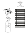
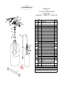
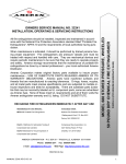
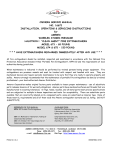
 INSPECTION, MAINTENANCE AND
RECHARGE SERVICE MANUAL
P/N 05603
RECHARGE FIRE EXTINGUISHERS IMMEDIATELY AFTER ANY USE
REFERENCES IN THIS MANUAL:
AVAILABLE FROM:
NFPA-10 Portable Fire Extinguishers
National Fire Protection Association
1 Batterymarch Park, P.O, Box 9101
Quincy, MA 02269-9101
CGA C-1 Methods for Hydrostatic Testing of
Compressed Gas Cylinders
CGA C-6 Standard for Visual Inspection of
Compressed Gas Cylinders
Compressed Gas Association, Inc.
4221 Walhey Road, 5th Floor
Chantilly, VA 20151-2923
AMEREX CORPORATION – P.O. BOX 81 – TRUSSVILLE, ALABAMA 35173-0081
Phone: 205/655-3271 Fax: 800/654-5980
e-mail: [email protected]
Web Page: http://www.amerex-fire.com
Printed in U.S.A. OM05603D Rev.6/12 Model 331—15 LB
Model 332—20 LB
Amerex Corporation makes original factory parts available to insure proper maintenance – USE OF SUBSTITUTE PARTS RELEASES AMEREX OF ITS WARRANTY
OBLIGATIONS. Amerex parts have machined surfaces and threads that are manufactured to exacting tolerances. O-rings, hoses, nozzles, and all metal parts meet
precise specifications and are subjected to multiple in-house inspections and tests
for acceptability. There are substitute parts available that may be incorrectly labeled
as UL component parts, some are advertised as Amerex type. None of these meet
UL requirements and all of them voids the Amerex extinguisher warranty and UL
listing. DO NOT SUBSTITUTE.
Model 322—5 LB
Model 330—10 LB
When maintenance is indicated, it should be performed by trained persons having
proper equipment. Fire extinguishers are pressure vessels and must be treated with
respect and handled with care. They are mechanical devices and require periodic
maintenance to be sure that they are ready to operate properly and safely.
Amerex strongly recommends that the maintenance of portable fire extinguishers be
done by a trained professional – your local authorized Amerex Distributor.
CARBON DIOXIDE HAND PORTABLE
FIRE EXTINGUISHERS
All fire extinguishers should be installed, inspected and maintained in accordance
with the National Fire Protection Association standard titled "Portable Fire Extinguishers", NFPA-10 and the requirements of local authorities having jurisdiction.
AMEREX CORPORATION DOES NOT SERVICE, MAINTAIN OR RECHARGE FIRE
EXTINGUISHERS. HIS MANUAL IS PUBLISHED AS A GUIDE TO ASSIST QUALIFIED
SERVICE PERSONNEL IN THE INSPECTION, MAINTENANCE AND RECHARGE OF
AMEREX FIRE EXTINGUISHERS ONLY.
NO INSTRUCTION MANUAL CAN
ANTICIPATE ALL POSSIBLE MALFUNCTIONS THAT MAY BE ENCOUNTERED IN
THE SERVICE OF FIRE EXTINGUISHERS. DUE TO THE POSSIBILITY THAT PRIOR
SERVICE PERFORMED ON THIS EQUIPMENT MAY HAVE BEEN IMPROPERLY
DONE, IT IS EXTREMELY IMPORTANT THAT ALL WARNINGS, CAUTIONS AND
NOTES IN THIS MANUAL BE CAREFULLY OBSERVED. FAILURE TO HEED THESE
INSTRUCTIONS COULD RESULT IN SERIOUS INJURY. AMEREX ASSUMES NO
LIABILITY FOR SERVICE, MAINTENANCE OR RECHARGE OF FIRE EXTINGUISHERS BY PUBLISHING THIS MANUAL.
FIVE YEAR LIMITED WARRANTY
Amerex warrants its fire extinguishers to be free from defects in material and workmanship for a period of five (5) years from the date of purchase. During the warranty
period, any such defects will be repaired or the defective extinguisher replaced if
only factory replacement parts and recommended service equipment have been used
to service the extinguisher. This warranty does not cover defects resulting from
modification, alteration, misuse, exposure to unusually corrosive conditions nor
improper installation or maintenance. All implied warranties, including, but not
limited to, warranties of fitness for purpose and merchantability, are limited to the time
periods as stated above.
In no event shall Amerex Corporation be liable for incidental or consequential damages. Some states do not allow limitations on how long
an implied warranty lasts or the exclusion or limitation of incidental or consequential
damages, so that the above limitations or exclusions may not apply to you. Amerex
Corporation neither assumes nor authorizes any representative or other person to
assume for it any obligation or liability other than expressly set forth herein.
This
warranty gives you specific legal rights, and you may also have other rights which
To obtain performance of the obligation of this
may vary from state to state.
warranty, write to Amerex Corporation, P. O. Box 81, Trussville, AL 35173-0081 for
instructions.
INSPECTING THE EXTINGUISHER
This extinguisher should be inspected at regular intervals (monthly or more often if
circumstances dictate) to insure that it is ready for use. Inspection is a “quick check”
that a fire extinguisher is available and is in operating condition. It is intended to give
reasonable assurance that the fire extinguisher is fully charged.
This is done by
verifying that it is in its designated place, that it has not been actuated or tempered
with, and that there is no obvious physical damage or condition to prevent its
operation.
OPERATION
NOTE:
Persons expected to use this extinguisher should be trained in initiating
its operation and in the proper fire fighting technique. Familiarize all personnel with this information before an emergency occurs.
WARNING:
Carbon Dioxide extinguishes fires by diluting the surrounding atmosphere with inert gas keeping the oxygen level below the percentage
required for combustion. When it is used in an unventilated space, such
as a small room, closet or other confined area, prolonged occupancy of
that space can result in loss of consciousness due to oxygen deficiency.
Avoid skin contact – CO2 is extremely cold and could cause burns or
frostbite.
1. Remove extinguisher from wall hanger or vehicle bracket and move it to
within approximately 6 feet (5 lb.) or 10 feet (10, 15 or 20 lb.) of the fire site.
2. Hold the extinguisher upright, twise and pull ring (safety) pin.
3. Stand back 6 feet (5 lb.) or 10 feet (10, 15 or 20 lb.) from the fire and aim the
horn at base of flames nearest you. Hold horn at base hand grip only—
grasping the horn or swivel discharge tube could cause cold burn.
4. Keeping the extinguisher upright, sweep side to side across the base of
the fire and past both edges. Progressively follow up until the fire is extinguished. Work the fire away from you while being alert for flashbacks.
Move closer as the fire is extinguished, but not so close as to scatter or
splash the burning materials.
5. When the fire is out, release the valve lever to stop discharge. Stand by
and watch for possible reignition.
6. Evacuate and ventilate the area immediately after extinguishing the fire.
The fumes and smoke from any fire may be hazardous and can be deadly.
DISCHARGE TIME (APPROXIMATELY)
5 lb – 9 seconds
10 lb – 10 seconds
15 lb – 12 ½ seconds
20 lb – 19 seconds
DISCHARGE RANGE (APPROXIMATELY)
5, 10, 15, 20 lb – 3 to 8 feet
RECHARGE FIRE EXTINGUISHERS IMMEDIATELY AFTER ANY USE
PERIODIC INSPECTION PROCEDURES
(Monthly or more often if circumstances dictate)
NFPA-10 Periodic inspection of fire extinguishers shall include a check of at least the following items:
1.
2.
3.
4.
5.
6.
Location in designated place.
No obstruction to access or visibility.
Operating instructions on nameplate and facing outward.
Safety seals and tamper indicators not broken or missing.
Examination for obvious physical damage, corrosion, leakage or clogged nozzle.
Determine fullness by weighing or hefting.
MAINTENANCE
At least once a year, or more frequently if indicated by an inspection, Maintenance should be performed. Maintenance is a "thorough check" of the extinguisher. It is intended to give maximum assurance that an extinguisher
will operate effectively and safely. It includes a thorough examination and any necessary repair or replacement.
It will normally reveal the need for hydrostatic testing. MAINTENANCE - SERVICE PROCEDURE
1. Clean extinguisher to remove dirt, grease or foreign material. Check to make sure that the instruction nameplate
is securely fastened and legible. Inspect the cylinder for corrosion, abrasion, dents or weld damage. If any of
these conditions are found and you doubt the integrity of the cylinder, hydrostatically test in accordance with CGA
Pamphlets C-1 and C-6 and NFPA 10.
2. Inspect the extinguisher for damaged, missing or substitute parts. Only factory replacement parts are approved
for use on Amerex fire extinguishers.
3. Weigh the extinguisher and compare with weight printed in the “Maintenance” section on the nameplate (label).
Recharge extinguisher if weight is not within indicated allowable tolerances.
4. Check the date of manufacture stamped on the cylinder dome. The agent cylinder must be hydrostatically tested
every 5 years to the test pressure indicated on the nameplate in accordance with DOT requirements.
5. Check ring pin for freedom of movement. Replace if bent or if removal appears difficult.
6. Inspect discharge lever for any dirt or corrosion which might impair freedom of movement. Inspect carrying
handle for proper installation. If lever, handle or rivets are damaged replace with proper Amerex part(s).
7. Remove the horn and discharge tube (5 lb.) or hose & horn assembly (10, 20 & 25 lb.),
8. Remove the horn and discharge tube (5 lb) or hose & horn assembly (10, 25 & 20 lb), inspect for damage, replace as necessary. Replace the horn if brittle, cracked or deformed. Blow air through nozzle and nozzle assemblies to insure passage is clear of foreign material.
9. Carbon dioxide hose assemblies have a continuous metal braid that connects to both couplings to minimize static
shock. A hose continuity test should be performed using a basic conductivity tester consisting of a flashlight having an open circuit and a set of two wires with a conductor (clamps or probe) at each end. (NFPA 10)
10. Inspect the valve assembly for corrosion or damage to hose thread connection. Visually inspect the safety relief
assembly for obstruction or damage – replace with complete Amerex factory assembled safety relief P/N 04000
(tighten assembly to 250 in-lbs of torque) if necessary. DO NOT SUBSTITUTE. Valve removal and/or valve part
replacement should be made only after completely discharging the contents of the cylinder.
11. Inspect the 10, 15 & 20 lb elbow and diffusion tip for blockage or damage. The Amerex 5 lb CO2 diffuser is built
into the discharge tube. Check elbow and discharge tube for blockage or damage. Replace damaged parts with
genuine factory replacement parts only.
12. Reinstall horn and discharge tube (5 lb) or hose and horn assembly (10, 15 & 20 lb) to discharge valve. Check
horn clip (10, 15 & 20 lb) for damage or proper positioning. Replace, tighten or realign as necessary.
13. Install new tamper seal and record service data on the extinguisher inspection tag.
14. Replace the extinguisher on the wall hanger or in the vehicle bracket making sure that it fits the bracket properly
and the bracket is securely attached – replace the bracket if necessary.
RECHARGE
WARNING: Before attempting to disassemble, be sure the extinguisher is
completely empty/depressurized.
Use only an approved source of carbon dioxide (see minimum
specifications in NFPA 10 "Inspection, Maintenance & Recharging".
Do not use dry ice convertors.
Use an approved pump, hose and recharge adapter to insure safe
and efficient charge operations.
RECHARGING PROCEDURE
1. Perform steps 1 through 10 of the "Maintenance-Service Procedure" section.
2. Discharge all remaining pressure and contents, making sure that there is no remaining pressure. Retighten valve
assembly. A proper valve installation occurs when the minimum tightness is used to make a leak-tight, valve-tocylinder seal. Do not over-tighten valves! (100 ft. lbs. [135.58 Nm] maximum torque). Over-tightening can
damage both valves and cylinders and may lead to unsafe situations that can cause property damage, injury and/
or loss of life.
3. Check the extinguisher nameplate (label) for the proper amount of CO2 to be pumped into the extinguisher.
4. Install the proper Amerex recharge adapter. Adapter must fit over diffuser tip on 5 lb Discharge Tube and elbow
on 10, 15 & 20 lb without blocking diffuser holes Do not remove 5 lb. discharge tube or 10, 15, 20 lb. elbow.
5. Place extinguisher on an accurate scale and attach carbon dioxide supply line to the recharge adapter.
6. Attach a device such as a "Pony Spring Clamp" to hold the extinguisher valve lever in the squeezed position or
open position. Pump the proper amount of CO2 into the extinguisher. When the proper weight is reached, release the clamp, shut off the CO2 pump and vent the supply line.
7. Remove the CO2 supply line and recharge adapter from the extinguisher valve.
8. Check the collar and valve for leaks using a leak detection fluid or a solution of soapy water. Remove leak detection fluid from the valve assembly and wipe exterior of the extinguisher to dry.
9. Install ring pin with ring facing the front of the extinguisher.
10. Install tamper seal. Record recharge date and attach new recharge tag.
11. Install the horn or hose and horn assembly to the extinguisher valve.
12. Weigh assembled extinguisher and confirm that the total weight is within the allowable tolerances indicated in the
Maintenance section of the nameplate (label).
TROUBLESHOOTING GUIDE
WARNING: Determine the source of a leak before the extinguisher is depressurized. The extinguisher must be completely depressurized before any attempt is made to devalve it and correct a
leakage problem. To depressurize – hold the extinguisher in a vertical position and slowly squeeze
the discharge handle. Thoroughly clean all valve parts after depressurization and valve removal.
Amerex CO2 valve bodies and aluminum cylinders are 1-1/8"-12 UNF straight threads. Use a proper
straight thread adapter when hydrostatically testing. When reinstalling the valve assembly, the cylinder must be placed in a suitable securing vice. Lubricate o-ring area only. Threads of straightthreaded cylinders require no lubricant for proper valve installation. A proper valve installation occurs when the minimum tightness is used to make a leak-tight, valve-to-cylinder seal. Do not overtighten valves! (100 ft. lbs. [135.58 Nm] torque). Over-tightening can damage both valves and cylinders and may lead to unsafe situations that can cause property damage, injury and/or loss of life.
PROBLEM 1. 2. CORRECTIVE ACTION Leak at collar o-ring Remove valve assembly, clean collar thoroughly
and install new collar o-ring. Lubricate with
Visilox V-711 and reinstall valve. Leak through valve Check valve stem seating area for scratches or
foreign matter. Clean seating area with a tooth
brush and soft cloth. Install new valve stem
assembly.
3. Leak at safety relief nut Remove safety nut, disc and gasket assembly.
Replace with new Amerex P/N 04000 safety nut,
disc and gasket assembly. Tighten assembly to
250 in-lbs of torque.
4. Leak during discharge
under discharge lever Remove valve assembly, downtube, spring and
valve stem assembly. Install new valve stem
assembly. Check valve seat for scratches or
foreign matter.
5. Leak during discharge at
hose connection elbow Tighten hose connection at elbow (10, 15, 20 lb).
replace o-ring and/or elbow on 5 lb.
Leak in the cylinder Contact Amerex if under warranty – otherwise
mark "Rejected" and remove from service or
return to the owner.
6. PARTS LIST
For
5 lb. Carbon Dioxide
Extinguishers
Model 322
Model 322MN
Item Part
No. Std
Description Valve Assembly (does not
include elbow or downtube Pkg 1 03090 1 2 04000 Safety Disc, Gasket & Nut 3 00160 Ring Pin, Stainless Steel 24 3A 00532 Chain (Nylon) for Ring Pin 24 4 01387 Lockwire Seal (Yellow) 5 07762 Lever & Rivet 5A 01563 Rivet only for Lever 6 09020 Handle & Rivets 6A 01564 Rivet only for Handle (2 reqd) 7 05689 O-ring for Elbow 6 8 02735 Elbow with O-ring 1 6 500 1 24 1 24 9 01769 Discharge Tube 1 10 01772 Horn 1 11 05235 Valve Stem O-ring 12 01539 Valve Stem Assembly 6 13 00501 Spring 6 14 00503 Retainer 1 15 00533 Downtube 1 16 01124 Collar O-ring 1-1/8" 24 24 ALL BRACKETS – SEE BRACKET PAGE ALL FILL & HYDROTEST ADAPTERS – SEE ADAPTER PAGE
ALL VALVE ASSEMBLIES INCLUDE VALVE BODY, VALVE
STEM ASSEMBLY, SPRING, RETAINER, LEVER & HANDLE PARTS LIST
For
10-15-20 lb. Carbon Dioxide
Extinguishers
Model 330 Model 331 Model 332
Ite
m Part
1 03090 2 04000 Safety Disc, Gasket & Nut 3 00160 Ring Pin, Stainless Steel 24 3A 00532 Chain (Nylon) for Ring Pin 24 4 01387 Lockwire Seal (Yellow) 5 07762 Lever & Rivet 5A 01563 Rivet only for Lever No. Std
Description Valve Assembly (does not
include elbow or downtube 6 09020 Handle & Rivets 6A 01564 Rivet only for Handle (2 req'd) Pkg 1 6 500 1 24 1 24 7 02309 Elbow with O-ring & Spacer 1 7A 05689 O-ring for Elbow 6 7B 02216 Nylon Spacer for Elbow 6 8 01776 Hose Assembly–330,331,332 1 01782 Hose & Horn Assembly-330 01705 Hose & Horn Assembly-331,332 10 00594 U-Pin 6 11 01777 Nozzle 1 00572 Horn – 330 00593 Horn – 331, 332 13 05235 Valve Stem O-ring 14 01539 Valve Stem Assembly 6 15 00501 Spring 6 16 00503 Retainer 1 00564 Downtube – 330 1 9 12 17 1 1 24 00589 Downtube – 331, 332 1 18 01124 Collar O-ring – 1 1/8" 24 19 02073 Horn Clip (Red) Strap (Red) for Horn Clip330,331 Strap (Red) for Horn Clip - 332 Screw & Nut for Horn Clip Strap
Assembly (NOT SHOWN) 20 * 05442 05441 04489 1 1 12 ALL BRACKETS – SEE BRACKET PAGE ALL FILL & HYDROTEST ADAPTERS – SEE ADAPTER PAGE
ALL VALVE ASSEMBLIES INCLUDE VALVE BODY, VALVE
STEM ASSEMBLY, SPRING, RETAINER, LEVER & HANDLE