1
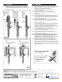
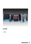
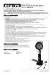
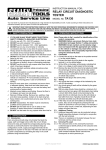
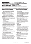
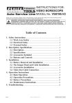
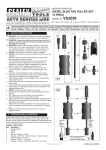
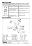
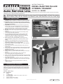
Instructions for: DIESEL INJECTOR PULLER CITROEN / PEUGEOT MODEL No: VS2005 Thank you for purchasing a Sealey product. Manufactured to a high standard this product will, if used according to these instructions and properly maintained, give you years of trouble free performance. IMPORTANT: PLEASE READ THESE INSTRUCTIONS CAREFULLY. NOTE THE SAFE OPERATIONAL REQUIREMENTS, WARNINGS AND CAUTIONS. USE THE PRODUCT CORRECTLY AND WITH CARE FOR THE PURPOSE FOR WHICH IT IS INTENDED. FAILURE TO DO SO MAY CAUSE DAMAGE AND/OR PERSONAL INJURY AND WILL INVALIDATE THE WARRANTY. PLEASE KEEP INSTRUCTIONS SAFE FOR FUTURE USE. 1. SAFETY INSTRUCTIONS WARNING! Ensure Health and Safety, local authority and general workshop practice regulations are adhered to when using tools. WARNING! Always use caution when working around fuel systems. The fuel in the fuel rail may be pressurised even if the engine is not running. IMPORTANT: These instructions are provided as a guide only. Always refer to the vehicle manufacturer’s service instructions, or a proprietary manual, to establish the current procedure and data, also any warnings or cautions particular to the vehicle. DO NOT use the set if any parts are missing or damaged. DO NOT use this tool for any purpose other than that for which it is designed. Switch off vehicle's ignition and disconnect the battery before commencing work under the bonnet. You must follow the vehicle's service manual cautions when working around the air bag system. If the cautions are not followed the air bag may deploy unexpectedly even after the ignition is turned ‘OFF’, resulting in personal injury. Never lay tools on the vehicle's battery. This may short the terminals together, causing harm to yourself, the tools, or the battery. Operate in a well ventilated area. Do not inhale fuel vapours. Wear approved eye protection. A full range of personal safety equipment is available from your Sealey dealer. Wear suitable clothing to avoid snagging. Do not wear jewellery and tie back long hair. Keep children and other unauthorised persons away from the working area. Keep yourself, tools, and test equipment away from hot engine parts. Always keep a fire extinguisher close by, that is suitable for fuel/ electrical/chemical fires. NEVER smoke or have open flames near vehicle. Always relieve fuel pressure before disconnecting fuel lines from injectors. Use a rag to cover fuel line fittings, when connecting or disconnecting fuel lines. Avoid contact with fuel. Clean up all fuel spills immediately and dispose of all rags properly. Maintain the tool components in good and clean condition for best and safest performance. When work on the vehicle is finished, ensure all connections on vehicle are restored, and that there are no tools left in the engine bay. Replace tools in the carrying case and store in a safe, dry, childproof location. fig.1 2.introduction & contents Comprehensive set for removing Citroen/Peugeot 2.0/2.2HDi 16v fuel injectors. Allows the removal of seized injectors without the need to remove the cylinder head. Bridge fits perfectly on the cylinder head preventing damage to the area surrounding the injector. Supplied in carry-case. Contents: (refer to fig.1) Item Description 1 Bridge 2 3 x Bridge Legs 3 2 x Force Screws - Thread 17mm, 25mm x Pitch 1mm 4Force Screw Nut 5 Injector Sockets 25mm, 29mm 6 Security Hex Key - ½"sq. drive fig.2 Original Language Version VS2005 Issue: 3 - 28/02/12 3.assembly 4.operation 3.1.Referring to the individual components in fig.1. assemble the Injector Puller minus the force screw as shown in fig.2. overleaf. a different configuration of the bridge legs may be needed depending on engine. 4.1. Before working on the fuel system, make sure that the fuel system is not pressurised. Refer to the manufacturer's instruction manual on how to de-pressurise the system. 4.1.1. Disconnect the injector wires and connections as per the manufacturer's instructions. 4.1.2.Remove any carbon build up from around the injector. 4.1.3.Remove the cap from the injector using the appropriate size socket (fig.3A). 4.2. Removing Inner Sleeve. (fig.3). 4.2.1.Remove the internal parts from the injector to gain access to use the security hex key (fig.3.6). It may be necessary to remove the injector veins by force. Insert the security hex into the inner sleeve. Turn the security hex anti-clockwise using a 21mm socket to remove the inner sleeve (fig.3B). 4.2.2. Select the appropriate force screw and screw into the threads of the injector and tighten with a suitable spanner (fig.3C). 4.3. Removing the injector. (fig.4). It will be necessary to remove the engine cam cover and possibly a manifold bolt, please refer to the manufacturer's manual for instruction. The removal of certain bolts from the engine will allow suitable space and support for the bridge legs to use. 4.3.1. Slide the bridge assembly over the force screw, inserting the legs into the appropriate holes for a sturdy footing (fig.4D). Note:One leg is flat and is to be used on the top of the cylinder head and not to be inserted into a bolt hole. 4.3.2. Screw the force screw nut onto the force screw until finger tight. 4.3.3.Using appropriately sized spanners, hold the force screw securely with one spanner, and tighten the nut with the other, the injector should gradually slide out. Note: An approximate force of NO MORE THAN 150Nm should be applied to the nut, and a socket should NOT be used. Whilst applying force, constantly check the seating of the tool and ensure that there is no twisting of the bridge assembly. 4.3.4. If the injector cannot be removed, it may be necessary to use a suitable penetrating oil and leave for a period of time, before applying force again. If the injector still cannot be removed, consult a main dealer or a diesel specialist, to avoid damage to the engine. 4.3.5. When an injector has been removed, it is recommended that only a new or refurbished injector is fitted. Follow the manufacturer's fitting and safety instructions. fig.3 ALWAYS KEEP FORCE SCREW WELL LUBRICATED. DO NOT USE AIR TOOLS, IMPACT WRENCHES, BREAKER BARS OR SOCKETS fig.4 NOTE: It is our policy to continually improve products and as such we reserve the right to alter data, specifications and component parts without prior notice. IMPORTANT: No liability is accepted for incorrect use of this product. WARRANTY: Guarantee is 12 months from purchase date, proof of which will be required for any claim. INFORMATION: For a copy of our latest catalogue and promotions call us on 01284 757525 and leave your full name and address, including postcode. Sole UK Distributor, Sealey Group, Kempson Way, Suffolk Business Park, Bury St. Edmunds, Suffolk, IP32 7AR Original Language Version 01284 757500 01284 703534 Web email www.sealey.co.uk [email protected] VS2005 Issue: 3 - 28/02/12