1
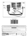
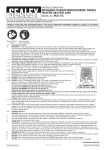
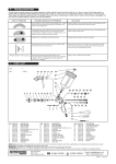
Instruction MANUAL for: relay circuit diagnostic tester Model no: TA130 Your new tester is produced and manufactured to a high standard of dependability and will, if used according to these instructions and maintained properly, give you years of trouble free performance. Important: Read these instructions carefully. Note THE SAFE OPERATIONAL REQUIREMENTS, WARNINGS AND CAUTIONS. USE THIS TESTER CORRECTLY AND WITH CARE FOR THE PURPOSE FOR WHICH IT IS INTENDED. failure to do so may cause damage AND/or personal injury and will invalidate the warranty. retain THESE INSTRUCTIONS for future use. 1. SAFETY PRECAUTIONS 3.OPERATING INSTRUCTIONS IF YOU ARE IN ANY DOUBT ABOUT ELECTRICAL SAFETY CONSULT A QUALIFIED ELECTRICIAN. Only for use with 12V - 24V DC systems. DO NOT use with industrial 110V systems. DO NOT use for domestic 110V - 230V applications. DO NOT use on any circuit directly or indirectly connected to AC lines or any other AC power source. Always check the instructions and procedures indicated in the vehicle service manual before attempting to disconnect any part or sub-system of the electrical circuit. DO NOT use if leads are damaged or if any wires are bared in any way. DO NOT use the equipment when you are tired or under the influence of alcohol, drugs or intoxicating medicines. DO NOT use this tool for any purpose other than that for which it has been designed. Observe standard workshop safety procedures when using the tester. Ensure vehicle ignition is switched OFF before connecting or disconnecting the tester. Ensure that, if working on the starter relay circuit, the vehicle is in neutral (or 'P' if an automatic) and that you keep clear of moving parts in case of unintentional starting. Keep the work area clean, uncluttered and ensure there is adequate lighting. Keep tools and other items away from the engine, and ensure you can see the battery and working parts of engine clearly. Maintain correct balance and footing. Ensure the floor is not slippery and wear non-slip shoes. Remove ill fitting clothing. Remove ties, watches, rings and other loose jewellery. Contain or tie back long hair. Keep children and unauthorised persons away from the working area. DO NOT disassemble. The tester must be checked by qualified service personnel only. DO NOT get the tester wet or use in damp or wet locations or areas where there is condensation. DO NOT use the tester for any purpose other than that for 2.INTRODUCTION 2.1 Introduction Fast, accurate and safe relay circuit tester that tests the supply, earth and trigger wires within the circuit. Simply remove the relay and install the corresponding dummy relay. Includes a universal fly lead for non-standard relay pin configurations. Earth, supply and trigger terminals will be displayed as a green or red LED. The tester can also be used to power components by simulating the relay in the on/off positions using the test button. © Jack Sealey Limited Note:Please refer to fig.1 overleaf for identification of the tester's components. p WARNING! Before use ensure that you have read, understood and apply Section 1 safety precautions. p WARNING! All pin numbers on the dummy relays must correspond with the appropriate pin numbers on the vehicle or damage may result when using the test buttons. This is especially important when using the universal fly lead. 3.1.Connection 3.1.1.Connect the red clip on the tester to the positive terminal (+) on the vehicle battery. 3.1.2.Connect the black clip on the tester to the negative terminal (-) on the vehicle battery. 3.1.3.All the LEDs on the tester will illuminate, indicating that there is no voltage or earth present at the test plug. 3.1.4.Remove the relay from the circuit to be tested and install the correct type of dummy relay into the relay socket (There are six different types of dummy relay supplied with the kit plus a universal fly lead for use with any type of vehicle relay socket). 3.1.5.Attach the test plug to the dummy relay. 3.2. Testing 3.2.1.Any circuits that have a voltage will be indicated by the red LED illuminating. 3.2.2.Any circuits going to earth will be indicated by the green LED illuminating. Note: With any relay circuits, there should be a minimum of at least one red and one green LED illuminated when testing a circuit. Both LEDs should not be illuminated at the same time for an individual circuit as this will indicate a fault within that circuit. Typically circuits 86 and 30 will illuminate red whilst circuit 85 will illuminate green. 3.2.3. If the relay circuits are serviceable (as indicated by the LEDs), they can be energised by pressing the test button 87 (and 87A for a five pin relay). For example: if the horn relay circuit is under test, depressing the test button will sound the horn. 3.3. Additional Testing 3.3.1. Additional diagnostic tests may be conducted using a Digital Automotive Analyser or test light in conjunction with the test terminals. Note:There is no resistance in the tester between the test terminals and the vehicle circuit. 3.4. Universal Fly Lead 3.4.1. The coloured wires on the universal fly lead have numbered tags to identify which pin the coloured wires correspond to. 3.4.2. Should the numbered tags become lost or illegible, the guide overleaf indicates which coloured wire corresponds to which particular pin. Original Language Version TA130 Issue: 2(S) - 31/07/13 fig.1 Universal Fly Lead Pin Identification Guide Wire Colour Pin Number Black 30 White 86 Blue 85 Green 87 Red 87A Parts support is available for this product. To obtain a parts list and diagram please log on to www.sealey.co.uk, email [email protected] or phone 01284 757500 Environmental Protection. Recycle unwanted materials instead of disposing of them as waste. All tools, accessories and packaging should be sorted, taken to a recycle centre and disposed of in a manner which is compatible with the environment. When the product is no longer required, it must be disposed of in an environmentally protective way. NOTE: It is our policy to continually improve products and as such we reserve the right to alter data, specifications and component parts without prior notice. IMPORTANT: No liability is accepted for incorrect use of this product. WARRANTY: Guarantee is 12 months from purchase date, proof of which will be required for any claim. INFORMATION: For a copy of our latest catalogue and promotions call us on 01284 757525 and leave your full name and address, including postcode. Sole UK Distributor, Sealey Group, Kempson Way, Suffolk Business Park, Bury St. Edmunds, Suffolk, IP32 7AR © Jack Sealey Limited Original Language Version 01284 757500 01284 703534 Web www.sealey.co.uk [email protected] TA130 Issue: 2(S) - 31/07/13