1
Errata
Title & Document Type: 5328A Universal Counter Option 011 Operating and Service Manual
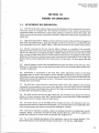
Manual Part Number: 05328-90019
Revision Date: December 1976
HP References in this Manual
This manual may contain references to HP or Hewlett-Packard. Please note that HewlettPackard's former test and measurement, semiconductor products and chemical analysis
businesses are now part of Agilent Technologies. We have made no changes to this
manual copy. The HP XXXX referred to in this document is now the Agilent XXXX.
For example, model number HP8648A is now model number Agilent 8648A.
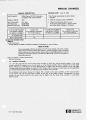
About this Manual
We’ve added this manual to the Agilent website in an effort to help you support your
product. This manual provides the best information we could find. It may be incomplete
or contain dated information, and the scan quality may not be ideal. If we find a better
copy in the future, we will add it to the Agilent website.
Support for Your Product
Agilent no longer sells or supports this product. You will find any other available
product information on the Agilent Test & Measurement website:
www.tm.agilent.com
Search for the model number of this product, and the resulting product page will guide
you to any available information. Our service centers may be able to perform calibration
if no repair parts are needed, but no other support from Agilent is available.
OPTION 011
HP-113 INTERFACE
For Universal Counter HP 5328A
INSTALLATION AND SERVICE MANUAL
SERIAL NUMBER
This manual applies directly to Option 011 A15 board
having serial number 1624 . For serial numbers above
1624, a "Manual Change" sheet is included with this
manual . For serial numbers below 1624, see backdating Section VI in this manual .
Copyright
HEWLETT-PACKARD COMPANY
1976
5301 STEVENS CREEK BLVD ., SANTA CLARA, CALIF . 95050
MANUAL PART NUMBER 05328-90019
Microfiche Par t Num ber 05328-90020
Printed : DEC 1976
HEWLETTT PACKARD
Option 011, Model 5328A
Table of Contents
TABLE OF CONTENTS
Page
Section
I
GENERAL INFORMATION . . . . . . . . . . . . . . . . . . . . . . . . . . . . . . . . . . . . . . . . . . . 1-1
1-1 .
Introduction . . . . . . . . . . . . . . . . . . . . . . . . . . . . . . . . . . . . . . . . . . . . . . . . . . 1-1
1-4.
Description . . . . . . . . . . . . . . . . . . . . . . . . . . . . . . . . . . . . . . . . . . . . . . . . . . . 1-1
II
INSTALLATION . . . . . . . . . . . . . . . . . . . . . . . . . . . . . . . . . . . . . . . . . . . . . . . . . . . . . . 2-1
2-5 .
Field Installation . . . . . . . . . . . . . . . . . . . . . . . . . . . . . . . . . . . . . . . . . . . . . . 2-1
2-7 .
Removal . . . . . . . . . . . . . . . . . . . . . . . . . . . . . . . . . . . . . . . . . . . . . . . . . . . . . 2-2
III
THEORY OF OPERATION . . . . . . . . . . . . . . . . . .
3-1 .
HP Interface Bus Description . . . . . . . .
3-12 . Option 011 HP-113 Interface Operation
3-17 .
Overall Operation . . . . . . . . . . . . . . . .
3-20 .
Bus Command Mode . . . . . . . . . . . . .
3-22 .
Listen Mode . . . . . . . . . . . . . . . . . . . . . .
3-24 .
Talk Mode . . . . . . . . . . . . . . . . . . . . . . .
Circuit Operation . . . . . . . . . . . . . . . . .
3-26 .
.
.
.
.
.
.
.
.
.
.
.
.
.
.
.
.
.
.
.
.
.
.
.
.
.
.
.
.
.
.
.
.
.
.
.
.
.
.
.
.
.
.
.
.
.
.
.
.
.
.
.
.
.
.
.
.
.
.
.
.
.
.
.
.
.
.
.
.
.
.
.
.
.
.
.
.
.
.
.
.
.
.
.
.
.
.
.
.
.
.
.
.
.
.
.
.
.
.
.
.
.
.
.
.
.
.
.
.
.
.
.
.
.
.
.
.
.
.
.
.
.
.
.
.
.
.
.
.
.
.
.
.
.
.
.
.
.
.
.
.
.
.
.
.
3-1
3-1
3-2
3-2
3-2
3-2
3-2
3-7
IV
MAINTENANCE . . . . . . . . . . . . . . . . . . . . . . . . . . . . . . . . . . . .
4-1 .
Introduction . . . . . . . . . . . . . . . . . . . . . . . . . . . . . . . . .
4-3.
Recommended Test Equipment . . . . . . . . . . . . . . .
4-5.
Verification of Performance . . . . . . . . . . . . . . . . . . .
4-8 .
Local Operation Test . . . . . . . . . . . . . . . . . . . . . . .
4-10 .
Verification Using a 9820A as a Bus Controller
4-18 .
Verification Using a 9830A as a Bus Controller
4-26 . Diagnostic Program and Troubleshooting . . . . . .
4-32 .
Option 011 Diagnostic Program . . . . . . . . . . . . .
4-40 .
ASM Flowchart . . . . . . . . . . . . . . . . . . . . . . . . . . . .
4-47 .
Troubleshooting Flowcharts . . . . . . . . . . . . . . . . .
4-53 .
ASM Troubleshooting . . . . . . . . . . . . . . . . . . . . . .
.
.
.
.
.
.
.
.
.
.
.
.
.
.
.
.
.
.
.
.
.
.
.
.
.
.
.
.
.
.
.
.
.
.
.
.
.
.
.
.
.
.
.
.
.
.
.
.
.
.
.
.
.
.
.
.
.
.
.
.
.
.
.
.
.
.
.
.
.
.
.
.
.
.
.
.
.
.
.
.
.
.
.
.
.
.
.
.
.
.
.
.
.
.
.
.
.
.
.
.
.
.
.
.
.
.
.
.
.
.
.
.
.
.
.
.
.
.
.
.
.
.
.
.
.
.
.
.
.
.
.
.
.
.
.
.
.
.
.
.
.
.
.
.
.
.
.
.
.
.
.
.
.
.
.
.
.
.
.
.
.
.
.
.
.
.
.
.
.
.
.
.
.
.
.
.
.
.
.
.
.
.
.
.
.
.
.
.
.
.
.
.
.
.
.
.
.
.
.
.
.
4-1
4-1
4-1
4-1
4-2
4-2
4-4
4-7
4-7
4-16
4-17
4-17
V
REPLACEABLE PARTS . . . . . . . . . . . . . . . . . . . . . . . . . . . . . . . . . . . . . . . . . . . . . . . . 5-1
5-1 .
Introduction . . . . . . . . . . . . . . . . . . . . . . . . . . . . . . . . . . . . . . . . . . . . . . . . . . 5-1
5-4.
Ordering Information . . . . . . . . . . . . . . . . . . . . . . . . . . . . . . . . . . . . . . . . . 5-1
VI
MANUAL CHANGES . . . . . . . . . . . . .
6-1 .
Introduction . . . . . . . . . . . . . .
6-3.
Manual Changes . . . . . . . . . .
6-5.
Newer Option 011 Boards
6-7.
Older Option 011 Boards
VII
SCHEMATIC DIAGRAMS . . . . . . . . . . . . . . . . . . . . . . . . . . . . . . . . . . . . . . . . . . . . . 7-1
7-1 .
Introduction . . . . . . . . . . . . . . . . . . . . . . . . . . . . . . . . . . . . . . . . . . . . . . . . . . 7-1
. . . .
. . . .
. . . .
. . .
. . . .
.
.
.
.
.
.
.
.
.
.
.
.
.
.
.
.
.
.
.
.
.
.
.
.
.
.
.
.
.
.
.
.
.
.
.
.
.
.
.
.
.
.
.
.
.
.
.
.
.
.
.
.
.
.
.
.
.
.
.
.
.
.
.
.
.
.
.
.
.
.
.
.
.
.
.
.
.
.
.
.
.
.
.
.
.
.
.
.
.
.
.
.
.
.
.
.
.
.
.
.
.
.
.
.
.
.
.
.
.
.
.
.
.
.
.
.
.
.
.
.
.
.
.
.
.
.
.
.
.
.
.
.
.
.
.
.
.
.
.
.
.
.
.
.
.
.
.
.
.
.
.
.
.
.
.
.
.
.
.
.
.
.
.
.
.
.
.
.
.
.
.
.
.
.
.
.
.
.
.
.
.
.
.
.
.
.
.
.
.
.
.
.
.
.
.
.
.
.
.
.
.
.
.
.
.
.
.
.
.
.
.
.
.
.
.
.
.
.
.
.
.
.
.
.
6-1
6-1
6-1
6-1
6-1
Option 011, Model 5328A
List of Tables
List of Figures
LIST OF TABLES
3-1 .
3-2.
3-3 .
American Standard Code for Information Interchange (ASCII) . . . . . . . . . . . 3-3
Addressing . . . . . . . . . . . . . . . . . . . . . . . . . . . . . . . . . . . . . . . . . . . . . . . . . . . . . . . . . . 3-4
Program Code Set . . . . . . . . . . . . . . . . . . . . . . . . . . . . . . . . . . . . . . . . . . . . . . . . . . . 3-5
4-1 .
4-2.
4-3 .
4-4 .
4-5 .
4-6 .
Recommended Test Equipment and System Equipment
Local Operation Test . . . . . . . . . . . . . . . . . . . . . . . . . . . . . . . .
9820A Verification Program . . . . . . . . . . . . . . . . . . . . . . . . . .
9830A Verification Program . . . . . . . . . . . . . . . . . . . . . . . . . .
Diagnostic Program List . . . . . . . . . . . . . . . . . . . . . . . . . . . . .
5328A Option 011 Signal Mnemonics . . . . . . . . . . . . . . . . .
5-1 .
5-2 .
Replaceable Parts . . . . . . . . . . . . . . . . . . . . . . . . . . . . . . . . . . . . . . . . . . . . . . . . . . . . 5-3
Manufacturers Code List . . . . . . . . . . . . . . . . . . . . . . . . . . . . . . . . . . . . . . . . . . . . . 5-5
6-1 .
Manual Backdating . . . . . . . . . . . . . . . . . . . . . . . . . . . . . . . . . . . . . . . . . . . . . . . . . . 6-1
.
.
.
.
.
.
.
.
.
.
.
.
.
.
.
.
.
.
.
.
.
.
.
.
.
.
.
.
.
.
.
.
.
.
.
.
.
.
.
.
.
.
.
.
.
.
.
.
.
.
.
.
.
.
.
.
.
.
.
.
.
.
.
.
.
.
.
.
.
.
.
.
.
.
.
.
.
.
.
.
.
.
.
.
.
.
.
.
.
.
.
.
.
.
.
.
.
.
.
.
.
4-1
4-2
4-3
4-5
4-8
4-21
LIST OF FIGURES
1-1 .
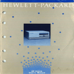
HP Model 5328A Option 011 HP-113 Interface
. . . . . . . . . . . . . . . . . . . . . . . . . . 1-0
3-1 .
3-2.
ASM Oscillator Timing Diagram . . . . . . . . . . . . . . . . . . . . . . . . . . . . . . . . . . . . . . 3-8
HP-113 Interface Block Diagram . . . . . . . . . . . . . . . . . . . . . . . . . . . . . . . . . . . . . . . 3-9
4-1 .
4-2.
4-3 .
4-4.
4-5 .
4-6.
4-7 .
4-8 .
4-9 .
4-10 .
4-11 .
4-12 .
4-13 .
4-14 .
4-15 .
4-16 .
4-17 .
4-18 .
4-19 .
4-20 .
4-21 .
4-22.
ASM Flowchart (Sheet 1 of 3) . . . . . . . . . . . . . . . . . . . . . . . . . . . . . . . . . . . . .
Local Troubleshooting Flowchart . . . . . . . . . . . . . . . . . . . . . . . . . . . . . . . . . .
Remote/Local Troubleshooting Flowchart . . . . . . . . . . . . . . . . . . . . . . . . .
LLO Troubleshooting Flowchart . . . . . . . . . . . . . . . . . . . . . . . . . . . . . . . . . . .
GTL Troubleshooting Flowchart . . . . . . . . . . . . . . . . . . . . . . . . . . . . . . . . . . .
TALK/UNTALK Troubleshooting Flowchart (Sheet 1 of 2) . . . . . . . . . . .
LISTEN/UNLISTEN Troubleshooting Flowchart . . . . . . . . . . . . . . . . . . . . . .
GET Troubleshooting Flowchart . . . . . . . . . . . . . . . . . . . . . . . . . . . . . . . . . . .
DCL Troubleshooting Flowchart . . . . . . . . . . . . . . . . . . . . . . . . . . . . . . . . . .
SDC Troubleshooting Flowchart . . . . . . . . . . . . . . . . . . . . . . . . . . . . . . . . . .
FUNCTION CODE and TIME BASE CODE Troubleshooting Flowchart
P Troubleshooting Flowchart . . . . . . . . . . . . . . . . . . . . . . . . . . . . . . . . . . . . .
R Troubleshooting Flowchart . . . . . . . . . . . . . . . . . . . . . . . . . . . . . . . . . . . . .
MULT Troubleshooting Flowchart . . . . . . . . . . . . . . . . . . . . . . . . . . . . . . . . .
ODU Troubleshooting Flowchart . . . . . . . . . . . . . . . . . . . . . . . . . . . . . . . . .
SAMPLE RATE Troubleshooting Flowchart . . . . . . . . . . . . . . . . . . . . . . . . .
ARMING Troubleshooting Flowchart . . . . . . . . . . . . . . . . . . . . . . . . . . . . . .
STORAGE Troubleshooting Flowchart . . . . . . . . . . . . . . . . . . . . . . . . . . . . .
DECADE RESET DISABLE and DIGIT OUTPUT Troubleshooting
Flowchart (Sheet 1 of 3) . . . . . . . . . . . . . . . . . . . . . . . . . . . . . . . . . . . .
OVERFLOW Troubleshooting Flowchart . . . . . . . . . . . . . . . . . . . . . . . . . . .
TALK ALWAYS Troubleshooting Flowchart . . . . . . . . . . . . . . . . . . . . . . . . .
ADDRESS SWITCH Troubleshooting Flowchart . . . . . . . . . . . . . . . . . . . . .
7-1 .
Option 011 A15 HP-113 Interface Assembly
.
.
.
.
.
.
.
.
.
.
.
.
.
.
.
.
.
.
.
.
.
.
.
.
.
.
.
.
.
.
.
.
.
.
.
.
.
.
.
.
.
.
.
.
.
.
.
.
.
.
.
.
.
.
4-23
4-28
4-29
4-30
4-31
4-32
4-34
4-35
4-36
4-37
4-38
4-39
4-40
4-41
4-42
4-43
4-44
4-45
.
.
.
.
.
.
.
.
.
.
.
.
4-46
4-49
4-50
4-51
. . . . . . . . . . . . . . . . . . . . . . . . . . . . . 7-3
Option 011, Model 5328A
General information
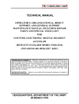
Figure 1-1 . HP Model 5328A Option 011 HP-1B Interface
Option 011, Model 5328A
General Information
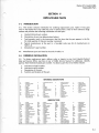
SECTION I
GENERAL INFORMATION
1-1.
INTRODUCTION
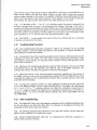
1-2 . This manual provides service and installation information for option 011 Hewlett-Packard
Interface Bus (HP-113) Interface to the Hewlett-Packard Model 5328A Universal Counter .
1-3 . The sections within this manual are labeled SECTION I GENERAL INFORMATION,
SECTION II INSTALLATION, SECTION III THEORY OF OPERATION, SECTION IV MAINTENANCE, SECTION V REPLACEABLE PARTS, SECTION VI MANUAL CHANGES, and
SECTION VII SCHEMATIC DIAGRAMS . These sections are designed to be compatible with the
same sections of the 5328A Service Manual . Programming information for Option 011 is contained in Section V of the 5328A Users Manual .
1-4.
DESCRIPTION
1-5 . Option 011 HP-113 Interface consists of one printed-circuit card (see Figure 1-1) that
mounts above and parallel to the A1 Motherboard in the 5328A . This option allows the 5328A
to output measurement data and be controlled via the HP-113 . The option is designed for use
with HP-113 compatible instruments, calculators, and computers . The functions of the 5328A
are fully programmable when this option is installed . Complete specifications for Option 011
are listed in Table 1-3 of the Users Manual and in the Service Manual for the 5328A .
NOTE
HP-IB Interconnect cable 10631A, B, C, or D is available as an accessory (not supplied with Option 011). The 10631A is 914 mm (3 feet)
long, 10631B is 1828 mm (6 feet) long, the 10631C is 3656 mm (12 feet),
and the 10631D is 500 mm (1 .5 feet) long.
Option 011, Model 5328A
Installation
SECTION II
INSTALLATION
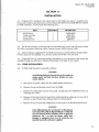
2-1 . If Option 011 is included in the initial order for the 5328A, the option is installed at the
factory and is ready for operation upon receipt. If Option 011 (HP Part No . 05328-80011) is ordered
for field installation, it will include the following parts :
ITEM
HP-113 Board
Cable Assembly
Cover Plate
Machine Screw
QUANTITY
HP PART NO .
1
1
1
4
05328-60019
8120-2176
05328-00014
2360-0115
2-2. The HP-113 connector mounting studs accommodate lock screws with 150 metric thread
M3 .5x0 .6 or equivalent Optimum Metric Fastener System (OMFS) thread 3.5P06.
2-3. Metric hardware supplied by HP for HP-113 connectors can be identified by the black finish .
If metric tools are not available, a 9/32 inch hex socket will fit the 7 mm hex stud .
2-4. Conversion kits for converting earlier instruments to use the metric lock screws are
available through any HP Sales or Service Office listed in the back of this manual .
2-5.
2-6.
FIELD INSTALLATION
To field install the option, proceed as follows:
CAUTION
Avoid flexing Option 011 board. Due to the number of
resistor packs and their location, flexing can cause
resistor failures .
a.
Disconnect the power cable from the 5328A (Safety Precaution).
b.
Remove the top and bottom covers from the 5328A .
c.
Remove the small plate from the rear panel, located above the STORAGE switch, by
removing two screws .
d.
Remove A4 Function Selector board from motherboard by pulling up on one end of
extractor at top of board (use rocking motion to extract board) .
e.
Remove the nut on each side of digital bus connector J6 on the HP-IB Interface board .
CAUTION
In the following step, be sure that pin 1 of the plug (on
each end of the cable) is aligned with pin 1 of the jack
(on each board) before inserting . (Pins on plugs are
numbered . Pin 1 on jacks has square solder dot.)
Damage to equipment may occur if connectors are
inserted incorrectly and power applied.
Option 01 1, Model 5328A
Installation
2-7.
f.
Connect one end of the 28-conductor cable to J-1 on the motherboard and insert the
cable through the slot of the main bracket, MP10 (refer to Figure 4-1 in the 5328A Service
Manual) and bend remaining end of cable over top of MP10.
g.
Install the HP-113 board, component side up (parallel to the motherboard) with digital
bus connector J6 inserted out through the rear panel (where plate was removed) .
h.
Place 5328A on its side and attach four 6-32x
from underside the motherboard .
i.
Mount the cover plate over digital bus connector J6 and switch S1 and attach with two
screws . Replace two nuts on J6 that were removed in step e .
j.
Connect the free end of the 28-conductor cable to J1 (position 35) on HP-113 board .
k.
Connect the end of the lock-out cable (jumper wire) to terminal post at pin 4 of XA16
(below display board) on motherboard .
I.
Install A4 Function Selector board removed in step d .
m.
Install top and bottom covers and apply power.
n.
Conduct the local operation test, Section IV Table 4-2, and one of the verification of
performance tests, Section IV either paragraph 4-10 or 4-18.
5/6
inch screws to the HP-113 board standoffs
REMOVAL
2-8 . Procedures for removal of Option 011 are essentially the reverse of the above installation
procedures .
Option 01 1, Model 5328A
Theory of Operation
SECTION III
THEORY OF OPERATION
3-1 .
HP INTERFACE BUS DESCRIPTION
3-2. The HP Interface Bus transfers data and commands between the components of an instrumentation system on 16 signal lines. The interface functions for each system component are
performed within the component so only passive cabling is needed to connect the system . The
cables connect all instruments, controllers, and other components of the system in parallel to the
signal lines .
3-3 . Eight of the lines (D101-D108) are reserved for the transfer of data and other messages in a
byte-serial, bit-parallel manner . Data and message transfer is asynchronous, coordinated by the
three handshake lines (DAV, NRFD, NDAC) . The other five lines are for control of bus activity .
3-4. Devices connected to the bus may be talkers, listeners, or controllers . The controller
dictates the role of each of the other devices by setting the ATN (attention) line low and sending
talk or listen addresses on the data lines (D101-D108) . Addresses are set into each device at the
time of system configuration either by switches built into the device or byjumpers on a PC board.
While the ATN line is low, all devices must listen to the data lines . When theATN line is high, only
devices that have been addressed will actively send or receive data. All others ignore the data
lines.
3-5 . Several listeners can be active simultaneously but only one talker can be active at a time .
Whenever a talk address is put on the data lines (while ATN is low), all other talkers will be automatically unaddressed .
3-6 . Information is transmitted on the data lines under sequential control of the three
handshake lines. No step in the sequence can be initiated until the previous step is completed .
Information transfer can proceed as fast as devices can respond, but no faster than allowed by the
slowest device presently addressed as active . This permits several devices to receive the same
message byte concurrently .
3-7 . The ATN line is one of the five control lines . When ATN is low, addresses and universal
commands are transmitted on only seven of the data lines using the ASCII {American Standard
Code for Information Interchange) code. When ATN is high, any code of 8 bits or less understood
by both talker and listener(s) may be used .
3-8 . The other control lines are IFC, REN, SRQ, EOI . IFC (interface clear) places the interface
system in a known quiescent state. REN (remote enable) is used with other coded messages to
select either local or remote control of each device .
3-9 . Any active device can set the SRQ (service request) line low . This indicates to the controller that some device on the bus wants attention, say a counter that has just completed a timeinterval measurement and wants to transmit the reading to a printer .
3-10. EOI (end or identify) is used by a device to indicate the end of a multiple-byte transfer
sequence . When a controller sets both the ATN and EOI lines low, each device capable of a
parallel poll indicates its current status on the DIO line assigned to it.
3-11 . For a more detailed description of bus operation, refer to the manual entitled "Condensed Description of the Hewlett-Packard Interface Bus", HP Part No. 59401-90030 .
Option 011, model 5328A
Theory of Operation
3-12.
OPTION 011 HP-113 INTERFACE OPERATION
3-13 . The 5328A HP-113 Interface is used to remotely program the 5328A and deliver the measurement results to the bus. Thus, the option operates both as a listen and as a talker .
3-14. As a listener, the interface is capable of programming most of the controls in the mainframe and all programmable modules that maybe installed . The HP-113 board contains storage circuits to control the mainframe remotely, and is set up to program the storage circuits in any programmable module .
3-15 . As a talker, the interface is capable of outputting the measurement data in exponential
format with a mantissa of nine digits (leading zeros are output as spaces) and an exponent of one
digit. Overflow and sign information is also contained along with a carriage return (CR), linefeed
(LF) termination to make it compatible with the standard HP-113 serial data format.
3-16. In addition to being a talker and listener, the HP-113 Interface follows a set of HP-113
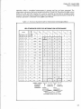
commands . This includes complete service request capability . The ASCII codes used for addressing and for data are shown in Table 3-1 . Address switch information is shown in Table 3-2 .
The program code set is shown in Table 3-3.
3-17.
Overall Operation
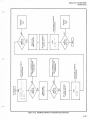
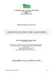
3-18. The heart of the HP-113 Interface is a 256 state algorithmic state machine (ASM) controlled
by a 256 x 16 ROM (U22) as shown in the block diagram Figure 3-2 . This state machine has two
different format states determined by the format (F) bit from U22 . One state (F=0) is an output
mode state where the machine will proceed sequentially to the next state (address) after storing or
outputting information . The other state (F=1) is a mode where the machine can either proceed to
the next line or perform a conditonal jump to a different line in the program . The decision as to
which state is chosen is made on the basis of whether the qualifier bit from U11A is low or high .
Preset counters U14 and U23 provide presetting to a jump statewhen F=1 and thequalifier is low .
These counters increment their count in all other cases . Altogether, there are 52 different bits that
may be selected as the qualifier for a particular state.
3-19 . Qualifier negate circuit U30C can invert the qualifier bit for any given state so that the
machine can branch on the qualifier being low or being high . U7 is added for psuedo subroutine
capability . I n the output mode, the ASM goes through the same group of states once for every
character being outputted on the bus. U7 is incremented every time so that the ASM can tell
which character it is to output.
3-20.
Bus Command Mode
3-21 . I n this mode (ATN low), the ASM accepts parallel bytes of information and decodes them
into bus commands . This usually requires setting or clearing bits of storage in U19 or U26 .
3-22.
Listen Mode
3-23 . I n the listen mode, the listen qualifier of U26 must below and ATN high . The interfacewill
then accept 8-bit parallel bytes continuously . When receiving theASCI I characters P, Q, U, R, orT
the counter will act upon the byte immediately (refer to programming in 5328A Users Manual) .
When receiving the letters F, G, A, B, C, D, orS the interfacewill then route anyASCII number or
numbers following these letters into particular storage registers . These registers are U28, U33, and
U34 along with any that are contained in any of the optional modules installed in the mainframe .
3-24 .
Talk Mode
3-25 . The HP-113 Interface will go into the talk mode if the talk qualifier of U26 is low or the talk
always switch is set to talk always and ATN high for both cases. There will be no output in normal
3-2
Option 011, Model 5328A
Theory of Operation
operation unless a completed measurement is present and has not been outputted . The
information to be put on the bus is latched into latches U15 and U24 . These drive the high current
buffers U5, U10, and U16 . Counter U7 is used as a pointer for the ASM to recognize which
character in the serial output string the interface is to output . Additional information on the HP-113
Interface operation is contained in the 5328A Users Manual .
Table 3-1 . American Standard Code for Information Interchange (ASCII)
USA STANDARD CODE FOR INFORMATION INTERCHANGE
b7
b6
b5
BITS
b4 b3 b Z
i i
bt
i
0
0
0
0
0
0
0
1
0
0
0
0
0
0 0
0
0
'0
;"1
COLU
i
00
3
0
NUL
DLE
SOH
DC1
4
SP
(b tan
0
2
STX
DC2
b
r
1
1
3
ETX
DC3
c
s
1
0
0
4
EOT
DC4
0
1
0
1
5
ENQ
NAK
0
1
1
0
6
ACK
SYN
BEL
ETB
01111 11
I
7
I
CAN
1 101011
I
9
I
h
EM
Y
z
0
1
0
10
LF
SUB
1
0
1
1
1 1
VT
ESC
k
1
1
0
0
12
FF
FS
I
1
1
0
1
13
CR
GS
m
1 11 1 1
I 0
RS
n
US
o
1
1
1
1
14
15
I
x
HT
1
I
I
SO
SI
I
UNIVERSAL
ADDRESS
COMMANDS
t
UNLISTEN
COMMAND
LISTEN
ADDRESSES
t
UNTALK
COMMAND
TALK
ADDRESSES
DATA WHEN ATN IS HIGH .
ADDRESSES WHEN ATN IS LOW.
I
DEL
Option 011, Model 5328A
Theory of Operation
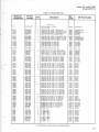
Table 3-2 . Addressing
ADDRESSABLE
1
0
TALK
ONLY
A5 A4 A3 A2 Al
1
1
ADDRESS SWITCHES
ASCII ADDRESS CODES
A5
0
0
0
0
0
0
0
0
0
0
0
0
0
0
0
0
1
1
1
1
1
1
1
1
1
1
1
1
1
1
1
3-4
0
0
0
0
0
0
0
0
1
1
1
1
1
1
1
1
0
0
0
0
0
0
0
0
1
1
1
1
1
1
1
A3
A2
Al
0
0
0
0
1
1
1
1
0
0
0
0
1
1
1
1
0
0
0
0
1
1
1
1
0
0
0
0
1
1
1
0
0
1
1
0
0
1
1
0
0
1
1
0
0
1
1
0
0
1
1
0
0
1
1
0
0
1
1
0
0
1
0
1
0
1
0
1
0
1
0
l
0
1
0
1
0
1
0
1
0
1
0
1
0
1
0
1
0
1
0
1
0
ASCII
LISTEN
ADDRESS
SP
!
"
#
$
%
&
'
)
+
,
/
1
2
3
4
5
6
7
8
9
<
=
>
ASCII
TALK
ADDRESS
A
B
C
D
E
F
G
H
I
J
K
L
M
N
0
P
Q
R
S
T
U
V
W
X
Y
Z
Option 011, Model 5328A
Theory of Operation
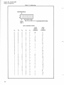
Table 3-3. Program Code Set
Codes shown in bold face are start-up conditions . These conditions are set by the code "P",
Remote Program Initialize, or by the bus commands Device Clear or Selected Device Clear .
1 . Initialization
P
Remote Program Initialize
2 . Function
F,0
Stop
F8
T .I . A-B
F1
Start A
F9
B/A
tF2
Start Clock
F:
T .I . Avg . A tF3
DVM/A
F;
Events C,T .I . A-B
F4
Freq . A
F<
Check
tF5
DVM/T .I .
A--B
F=
C/A
F6
Period A
F>
Freq . C
F7
Per . Avg . A
F?
DVM
3.
Time Base
Code
G,0
Gl
G2
G3
G4
G5
G6
G7
4.
5.
6.
7.
8.
9.
10 .
11 .
Freq Res
1 MHz
100 kHz
10 kHz
1 kHz
100 Hz
10 Hz
1 Hz
0 .1 Hz
Multiplier
1
10
102
10;
104
105
106
107
Time Res
(Std)
100ns
1 ws
lops
loops
lms
10ms
looms
1s
Time Res
(Opt. 040)
10ns
loons
l fts
lops
loops
1ms
loms
looms
Single-Multiple Measurement
S;0
Single Measurement
Sl
Multiple Measurement
Measurement Cycle
S2
Wait to output ; Service Request at end of measurement
S3
Continue cycle ; no Service Request
Output Mode
S4
Output at end of measurement
S5
Output when addressed (on-the-fly)
Sample Rate
S6
Maximum
S7
Manual control (from front panel)
Arming
S:
Off
S;
On
Display Storage
S<
On (normal)
5=
Off
Decade Reset
S>
Normal
S?
Disabled (for cumulative measurements)
Display Blanking
U
Normal display
Q
Blank display (digits and decimal point)
tFunctions not labeled on instrument front panel
3-5
Option 011, Model 5328A
Theory of Operation
Table 3-3. Program Code Set (Continued)
12 .
13 .
14 .
15 .
Channel A Signal Conditioning
a . Impedance
Ap
1 Megohm
A1
50 Ohms
b . Coupling
A2 AC
A3 DC
c . Slope
A4 +slope
A5 -slope
d . Attenuator
A6 x10
A7 x1
Separate - Common
A8 Separate
A9 Common A
Check
A< Normal Operation
A? Check, Measures internal clock
Code groups 12 to 18 apply
only when Option 041 is installed .
Trigger Level A
.volts
tenths of volts
rhundredths of volts
A{+fd, d 2 d 3
Permissible trigger level range : -2.50V to +2 .50V .
The program sequence to set trigger level starts with the channel designation letter followed
by a "+" or "-" sign . Next, three digits set the voltage level . An "*" terminates the sequence .
The same sequence must be used even to set 0 volts .
Examples :
16 .
17 .
18 .
19 .
"A+000*"
0 volts
"A-123*" -1 .23 volts
Channel B Signal Conditioning
a . Impedance
B0
1 Megohm
131
50 ohms
b . Coupling
B2 AC
B3 DC
c . Slope
B4 +slope
B5 -slope
d . Attenuator
B6 x10
B7 x1
Trigger Level B
BI+Id, d 2 d 3
See Group 15, Trigger Level A, for details .
Channel Invert
B8 Normal
B9 Invert A and B inputs
Reset ; Trigger
(Also see Bus Command GET)
R Reset, no trigger
T Reset and trigger
Option 011, Model 5328A
Theory of Operation
3-26.
3-27 .
Circuit Operation
The following paragraphs describe the circuit operation of Option 011 .
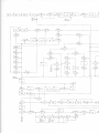
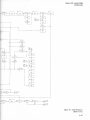
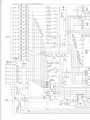
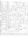
3-28 . STATE COUNTERS . As shown in the schematic diagram, Figure 7-1, the state of the ASM
ROM (current state and next stat-e) is determined by State Counters U14 and U23 . These counters
form an 8-bit presettable binary counter. When pin 1 of U25 is low, the counters will always
increment. When pin 1 of U25 is high, the counters will preset (jump to another state in the
program) if the output of U30C is high . The preset address is supplied to the State Counters input
from the ROM . The program is shown in the operational flowchart, Figures 4-1, 4-2 and 4-3. The
output of U30C is determined by the "not" bit from the ROM (through U21E) and the output of
the Qualifier FF U11A . The preprogrammed state of the "not" bit determines whether a high or
low output of the qualifier FF will result in a jump in the program . (This is shown in the ASM
Operational Flowchart, by the use of the letter "N" in a decision diamond symbol .) The preset
(jump) is synchronous and only occurs when pin 9 of U14 and U23 is low and when there is a rising
edge at pin 2 of U14 and U23. FF U31A synchronizes the reset of the State Counters to occur at the
proper time .
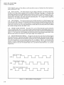
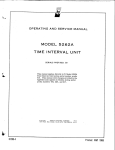
3-29 . ASM OSCILLATOR . As shown in the ASM Oscillator Timing Diagram, Figure 3-1, the
ASM oscillator circuit provides three separate phases of clock outputs . Schmitt trigger U18A is the
fundamental oscillator element which uses hysteresis to develop oscillation . The output of U18A
(through U13) strobes storage latches U11A and B, U15, U19, U24, U26, U28, U33, U31B and U34.
The output of U18A is also sent through a delay circuit consisting of resistor R14 and capacitorC4
into U18B to provide another phase of the clock output that determines the next state of theASM .
In addition, the output of U18A is sent through U30A to provide a third clock phase which is
applied to U31A . The output of U31A resets the 8-bit State Counter synchronously at power up or
when the IFC signal occurs . (Synchronous reset prevents loading the storage latches with
erroneous data .) The IFC signal also resets U26 (ASM storage) . The power up reset circuit U18C
and U18D clears all storage elements .
3-30 . BUS INTERFACE . The bus interface circuit consists of bus line termination resistors, data
output drivers and data input buffers . Resistors R29 and R30 form the line termination networks,
U4 is used to buffer the bus line inputs and U5, U10, and U16 are high current drivers that drive the
bus line output . The ATN signal is sent through U9A and U29D to ensure that the gates connected
to bus lines D101-D107 and DAV do not output when ATN goes true . The DAO signal from
U24(9) arms the DAC signal through U17B to ensure that DAC goes false within a few gate delays
after ATN goes true . (In some cases, the DAC response from the ROM may be too slow .) After
ATN is true, DAO is set to a "0" to allow normal operation of the DAC line .
3-31 . END OF MEASUREMENT . When a measurement has been completed, FF U11B is set .
This FF is clocked by the closing edge of the LMG signal . Diode CR2 and transistor Q3 keep U11B
from going to the "1" state when LRES is low or HRD is high . (During these times the counter is
being reset and noise appears on the LMG line which could trigger U11B) .
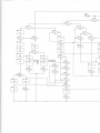
3-32 . QUALIFIER MULTIPLEXERS . Five 8to1multiplexersareconnected toallow 36lines tobe
multiplexed into 1 line . ASM ROM U22 controls multiplexers U3, U6, U8, and U32 to select
individual line qualifiers and U12 to select one of these multiplexers . I n addition, U12 checks the
output of auxiliary State Counter U7, a 4-bit binary counter that allows the same sequence of
states to be repeated up to 16 times. In the output algorithm, each state represents an output
character . Qualifier FF U11A eliminates erroneous results by ensuring that the State Counters U14
and U23 are not clocked when a qualifier is changing states . This would cause a partial preset and
partial increment of the State Counters .
3-33 . ADDRESSING . Address Comparator U2 monitors the Data Input/Output (DIO) lines 2
through 5 and the address switch (S1) settings . When a comparison occurs between the state of
these DIO lines and the address switch settings, U2 sends qualifier ADDR to multiplexer U8 . The
3-7
Option 011, Model 5328A
Theory of Operation
TALK ALWAYS section of the address switch provides a means of setting U6 so that interface is
always addressed to talk.
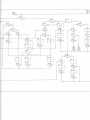
3-34. DATA OUTPUT . The Data Output circuit outputs characters on the bus data lines .
Storage circuit U24 transfers outputs from the ROM to DIO lines 5 through 7. U15 selects data
from either the ROM or the 5328A data bus and transfers it to DIO1-D104 . The state of the "not"
bit from ROM U22(13) through U21E determines the selection made by U15 . A displayed digit is
selected from the 5328A, any other characters (decimal point, "E", carriage return, exponent,
linefeed, etc .) are selected from the ROM .
3-35 . ASM STORAGE . The internal memory for the ASM operation is in ASM Storage circuits
U19, U26, and U31B . There are 17 information bits that can be set or cleared bythesecircuits .This
section also includes one-shot U1 which outputs a 1 ms pulse (LRST) to ensure reliable operation
of the state control circuit U4 on the motherboard . Diode CR3 ensures that LINH is low to inhibit
the counter during the time that LRST is low .
3-36. STROBE ENABLE DECODER . Decoder U13 is a 4 to 10 line decoder used to strobe the
various storage latches . Pins 1, 14, and 15 are used to select the device to be strobed and pin 2 is an
enable which determines the width of the strobe pulse . This pulse is shown by the shaded area in
Figure 3-1 . The output of U25C disables U13 when the ASM is in the decision state mode. In the
decision state mode, the format bit U22(17) goes high which disables U13 .
3-37. REMOTE PROGRAM STORAGE . Storage circuits U28, U33, and U34 are used to program
instrument functions . U28 stores Time Base codes in 3-bit bytes and U34 stores Function codes in
4-bit bytes . U33 stores 8 bits of information, one-bit at a time . The Sample Rate, Arming, Storage
Off, and Decade Reset can be programmed by U33 . In addition, U33(4, 5, and 6) control the
manner in which measurements are made and output to the bus. The inputs to the remote
program storage circuits are the Module Data A, B, C, and D lines from DIO lines, 1, 2, 3, and 4,
respectively .
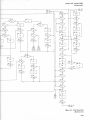
NEXT STATE OF ASM
U18(6)
STROBE STORAGE LATCHES
U18(3)
RESET BINARY COUNTERS U14, U23
U30(3)
Figure 3-1 . ASM Oscillator Timing Diagram
3-8
OSC
OSC
HP-113
HP-I B
PRESET COUNT
FOR STATE
LINKAGE U14,
HP-113
MEMORY
DEVICE
SELECT
COUNTERPROGRAM
DATA LATCHES
U28, 33, 34
LATCH
STROBE
LOGIC
LARM
HRD
LT R
SR T
TO COUNTEF
FN CODE
TB CODE,
CLK
4K
ROM
U22
PRESET COUNTER
FOR STATE
LINKAGE U14, L3
ASM
PROGRAM
STORAGE
LATCHES
19,26
NEXT
STATE
PROGRAM STOR
MULTIPLEXE
U6,32
LATCH
SELECT
CODE
INI
SE
CO
SET/COUNT
LOGIC
IA,25A,30C
U12
CONDARY
_TIPLEXER
ESTATE
UNTER U6
ASCII
OUTPUT
CHARACTERS
BUS OUTPUT
LATCHES
U15,24
BUS
DRIVERS
U5, 10, 16
Option 011, Model 5328A
Theory of Operation
HP-IB
MEMORY
DEVICE
SELECT
COUNTER PROGRAM
DATA LATCHES
U28, 33, 34
LATCH
STROBE
LOGIC
ASM
PROGRAM
STORAGE
LATCHES
19,26
LARM
HRD
LT R
RBI
TO COUNTER
FN CODE
TB CODE,
CLK
PROGRAM STORAGE
MULTIPLEXER
U6,32
LATCH
SELECT
CODE
ASCII
OUTPUT
CHARACTERS
BUS OUTPUT
LATCHES
U15, 24
INPUT
SELEC"
CODE
BUS
DRIVERS
U5,10,16
HP-113
Figure 3-2 . HP-IB Interface Block Diagram
3-9
Option 011, Model 5328A
Maintenance
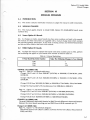
SECTION IV
MAINTENANCE
4-1 .
INTRODUCTION
4-2. This section contains maintenance and service information . Included is a table of recommended test equipment, verification of performance tests, a diagnostic program, an ASM flowchart, troubleshooting flowcharts, and troubleshooting information .
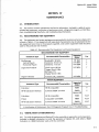
4-3.
RECOMMENDED TEST EQUIPMENT
4-4. Test equipment and system equipment recommended to maintain and service Option 011
is listed in Table 4-1. Test equipment with equivalent characteristics may be substituted for the
test equipment listed . Due to the programs supplied, only system equipment listed should be
used for the particular test involved .
Table 4-1 . Recommended Test Equipment and System Equipment
RECOMMENDED TEST EQUIPMENT
Instrument Type
Recommended Characteristics
Suggested
Model
Use
Oscilloscope
Vertical Plug-In
Horizontal Plug-In
Bandwidth : 50 MHz
Sensitivity : 50 mV/cm
Sensitivity : 1 ms/cm
HP 180A
HP 1801A
HP 1820A
T
T
T
Logic State Analyzer
Clock Input : 60 kHz
Trigger Word : 8 Bits
Bit fnput: TTL
Display Word : 8 Bits
`HP 1601A
T
Digital Voltmeter
Function : DC, resistance
HP 3490A
T
Suggested
Model
Use
9820A
V
59405A
Option 020
V
SYSTEM EQUIPMENT
Instrument Type
Recommended Characteristics
Calculator
HP-IB compatible
HP-IB Calculator Interface
Connects 9820A to HP-113
Calculator
HP-113 compatible
9830A
V,D,T
Printer
Compatible with 9830A
9866A
V,D,T
HP-113 Calculator Interface
Connects 9830A to HP-113
59405A
Option 030
V,D,T
V=Verification of Performance Test, D=Diagnostic Program Test, T=Troubleshooting
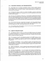
4-5.
VERIFICATION OF PERFORMANCE
4-6. To verify the performance of Option 011, a bus controller is required to control operation.
Included is detailed information to verify the operation of Option 011, with either a 9820A
Calculator or a 9830A Calculator used as the bus controller .
Option 011, Model 5328A
Maintenance
4-7. Before using one of the bus controllers and test programs to verify proper operation of
the interface, a preliminary test must be performed . The preliminary test is called the Local
Operation Test .
4-8.
Local Operation Test
4-9. Table 4-2 shows the preliminary test . This test checks for proper local operation, and
must be performed prior to the verification of performance test .
Table 4-2. Local Operation Test
Test Description and Expected Results
Instrument Setup and Test Procedure
Set 5328A Counter with
follows :
FUNCTION . . . . . . . .
FREQ RES . . . . . . . . . .
SAMPLE RATE . . . . . .
ARMING . . . . . . . . . .
STORAGE . . . . . . . . . .
OSCILLATOR . . . . . .
4-10 .
Option 011 as
.
.
.
.
.
.
.
.
.
.
.
.
.
.
.
.
.
.
.
.
.
.
.
.
.
.
.
.
.
.
.
.
.
.
.
.
.
.
.
.
.
.
. CHECK
.1 kHz
. . . CCW
. . . . OFF
. . . . ON
. . . . INT
5328A with Option 011 should be displaying
10 .0000 MHz
The counter should also be gating and controllable by the sample rate .
If the counter fails the above test, disconnect
one end of the 28-conductor cable, and perform the test again . If the counter passes,
refer to Local Troubleshooting Flowchart.
Verification Using a 9820A as a Bus Controller
4-11 . When a 9820A is used as a bus controller to make a verification of performance check,
the following equipment is required :
Model 5328A Counter with Option 011
Model 9820A Calculator with ASCII Bus Interface Model 11144A-020
4-12 .
Connect the equipment as follows:
a.
Insert the peripheral control 11224A PC II ROM in ROM slot three of the 9820A
Calculator .
b.
c.
Insert the 59405A HP-113 Calculator interface card into one of the 9820A I/O slots.
Connect one end of a Bus interface cable (any of the four lengths available) to the
Option 011, and the other to the 59405A Interface card .
4-13 . Before loading the program, press the END and EXECUTE keys . This positions the program counter to zero . Press the remaining keys in the program, as shown in the calculator key
column of Table 4-3.
4-14 .
9820A program list and program response
9820A Program Listing
9820A Program Response
: 1 I~'I I "'I !"'! 1:J
: !:~i
..
:: i....
.
.... ...
i
.. . . .
.L.~ ~. ., i._~
.
.. .
.
....
.. . :
. ..
..
i...i
,
I,
C'
r
.~
...
...
. ..
... ~...
J
4; ;1
I'J
1 :;1
:::;1 1',11 ; ;11 : ;11:;I 1": 1!" 1 ! : I
T.
I
!::! !::! I: 1 ! : :I
::
!,...1 !:. .1 ! :''.!
! : :!! :~!:. .1!1F .I!1f: :I
!:''!
F!
4-2
...
i;'i
!: I
. ::
Option 011, Model 5328A
Maintenance
Table 4-3 . 9820A Verification Program
PROGRAM
LINE NO .
COMMAND
0
CMD
0
PROGRAM DESCRIPTION
Control statement . Refer to 11222A peripheral control II operating manual HP Part No .
09820-99024, page 2-11 .
CALCULATOR
KEY
Bus Command
First quotes following CMD statement
specifies address mode .
"
?
0
?
0
Unaddresses all listeners on the Bus
Y
Calculator's talk address, puts calculator in
talk mode .
0
9
5328A's listen address, puts 5328A in remote
and listen mode .
9
Terminates command mode
"
0
0
Delimiter between modes
0
Second quote field, after CMD statement,
specifies data mode .
"
0
P
5328A remote program initialize (refer to
Table 3-3 Program Code Set)
P
0
F<
5328A program code for check
F
<
0
G6
5328A program code for 1 s gate time
0
T
G
6
5328A reset and trigger command
T
0
Terminates data mode
"
0
Delimiter between modes
0
Specifies address mode
"
0
?
Unaddresses all listeners on the bus
?
0
Y
0
5328A's talk address, puts 5328A in talk mode .
Y
5
9820A's listen address, puts 9820A in listen
mode
5
0
Terminates address mode
0
STORE
1
FMT*
1
1
Stores program line 0 into calculators storage
Defines free-field format, refer to 11224A
peripheral control II operating manual
"
STORE
FORMAT
End of statement delimiter
RED13,A
Reads data, over the Bus through the interface card into register "A"
RED
1
3
A
1
1
En d of state ment delimiter
FLT8
1
1
L-
FLOAT
8
End of statement d elimiter
DSP A
1
1
Specifies 8 digits to the right decimal
Causes contents of "A" register to be
displayed
DISPLAY
A
End of statement delimiter
PRTA
Causes contents of "A" register to be printed
1
PRINT
A
STORE
Stores program line 1 into calculator memory
STORE
2
GO TO 0
2
STORE
3
END
3
STORE
Causes program to loop back and execute line
0 again
Stores line 2 in memory
Ends program
Stores program line 3 into calculator
GTO
0
STORE
END
STORE
Option 011, Model 5328A
Maintenance
4-15 . To verify proper program loading, press the END and LIST keys. This gives a printed
listing starting from line zero. Check the program listing received against the listing in 4-14
to assure proper program loading .
4-16. Running the program is accomplished by pressing the END and RUN PROGRAM keys .
The program will continue to run and printout until the STOP key is pressed .
4-17. Successful completion of the verification test is shown by the 9820A Program response
in paragraph 4-14.
4-18.
Verification Using a 9830A as a Bus Controller
4-19. When a 9830A is used as a bus controller to make a verification of performance check,
the following equipment is required .
Model
Model
Model
59405A
4-20.
5328A
9830A
9866A
HP-113
Counter with Option 011 under test
Calculator
Printer
Calculator Interface (Option 030)
Connect the equipment as follows :
a.
Connect the 9866A to the 9830A as outlined in the HP 9866A Printer peripheral manual .
b.
If the 9830A does not have Option 274, insert Extended I/O ROM 11272B in any available ROM slot .
c.
Insert the 59405A HP-113 Calculator interface card into one of the 9830A I/O slots .
d.
Connect one end of a bus interface cable to Option 011, and the other to the 59405A
Interface card.
4-21 . Before loading the program, press the SCRATCH and EXECUTE keys . This clears the
memory and allows the new program to be entered . Press the remaining keys in the program,
as shown in the calculator key column of Table 4-4.
4-22.
9830A program listing and program response.
9830A Program Listing
..
, .' ; .,
7
T'
.
F', . . I ; :~:'. ~" ~:: :~ .
. ~ . . . .~..
. .j . .
~::,
I.
~.. j
I
i' .~..
F:,
:::!
t'~ ! . ..
.~ ,!
.i . I ::a
~ .a ! .
I
. . ..
I.
. . i . . .~
,:,
.I .
:
Ir :i
.
9830A Program Response
!: ;
~~
:.. ! :I
,
~ ..
. .. i . .
;
..
A.
: : :!
... .. . . .
!: !
...
!, I !. I
i I° :!
:: .I
F ! ::! F! 61 1': 11" ,
1 ;1 I; 11; ;
F :1
F! !' 1
F1
I::!1':Il ; ;ll ;li !
;
...!
'.''!
. I:
1D
I I; i 1;1 I : : .11:::1
1::1 I . :I I.:I k:
1,:11 :,9
4-23. To verify program loading, press the LIST and EXECUTE keys . This gives a program
listing from the 9866A Printer . Compare the printed listing received, against the 9830A program listing in 4-22 to assure correct program loading .
4-24. To run the program, press the RUN and EXECUTE keys. The program will continue to
run and printout until the STOP key is pressed .
4-25 . Successful completion of the 9830A verification program is shown by the 9830A Program response in paragraph 4-22.
Option 011, Model 5328A
Maintenance
PROGRAM
LINE NO .
10
Table 4-4. 9830A Verification Program
COMMAND
10
PROGRAM DESCRIPTION
Defines statement line number
10
FORMAT 10B Defines binary format that can be called by
its line number
10
END OF LINE
20
20
20
Stores line number 10 into memory of
Calculator
Defines statement line number
OUTPUT(13,10) Output statement, causes 768 to be sent over
768
the bus (select code 13) in the format of line
10 . (Refer to 9830A HP Interface Bus Users
Guide. HP Stock No . 59300-90002)
CALCULATOR
KEY
1
0
FORMAT
1
0
B
END OF LINE
2
0
OUTPUT
1
3
1
0
7
6
8
20
End of statement delimiter
20
END OF LINE
30
30
30
CMD
30
30
?
Stores line number 20 into memory of
Calculator
Defines statement line number
END OF LINE
3
0
Bus command statement. Defines following
information as bus data or command
information
C
M
D
First quote field following CMD statement
specifies command mode
"
Unlistens all listeners on the bus
?
30
1A
Calculator talk address. Places Calculator in
talk mode .
,u
30
9
5328A listen address. Places 5328A in listen
mode
9
30
Terminates command mode
"
Delimiter between modes (command and
data)
,
30
Second quote field specifies data mode
P
30
"
30
P
5328A programming code for remote program
initialize (refer to Table 3-3 Program Code Set)
30
F<
5328A program code for check function
F
30
G6
5328A program code for 1 second gate time
30
T
G
6
30
5328A program code for reset and trigger
command
Terminates data mode
T
Option 011, Model 5328A
Maintenance
Table 4-4 . 9830A Verification Program (Continued)
PROGRAM
LINE NO .
COMMAND
PROGRAM DESCRIPTION
CALCULATOR
KEY
30
Delimiter between modes
,
30
Third quote field following CMD statement
specifies address mode
"
30
?
Unlistens all listeners on the bus
?
30
Y
5328A talk address . Places 5328A in talk mode
Y
30
5
Calculator listen address . Places calculator
in listen mode .
5
Terminates address mode
"
30
30
END OF LINE
40
40
40
ENTER(13,*)A
Stores line number 30 into memory of
calculator
Defines statement line number
Enters data over 13 (bus) in *(free-field
format) into the "A" register of the calculator
END OF LINE
4
0
ENTER
1
3
*
A
'
40
END OF LINE
50
50
50
DISP A
50
END OF LINE
60
60
60
PRINT A
60
END OF LINE
70
70
70
GT030
70
END OF LINE
80
80
80
END
80
END OF LINE
Stores line number 40 into memory of
calculator
Defines statement line number
Causes contents of "A" register of calculator
to be displayed .
Stores line number 50 into memory of
calculator
Defines statement line number
Causes contents of "A" register to be printed
by 9866A
Stores line number 60 into memory of
calculator
END OF LINE
5
0
DISP
A
END OF LINE
6
0
PRINT
END OF LINE
Defines statement line number
7
0
Causes program to loop back to line 30
G
O
T
O
3
0
Stores line number 70 into memory of
calculator
Defines statement line number
Ends program
Stores line number 80 into memory of
calculator
END OF LINE
8
0
END
END OF LINE
Option 011, Model 5328A
Maintenance
4-26.
DIAGNOSTIC PROGRAM AND TROUBLESHOOTING
4-27. Since Option 011 is an interface controlled by software, effective problem diagnosis
and troubleshooting require a thorough understanding of program execution . The interface connects the 5328A Counter to the HP-113 . Therefore, a good understanding of the 5328A Counter
and the HP-113 is also required .
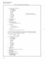
4-28. The diagnostic program in Table 4-5 is written for the 9830A . It performs overall testing
and failure diagnosis of Option 011 . A description of its use and an explanation of each test are
included with the program .
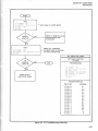
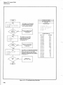
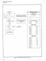
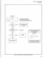
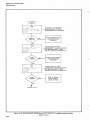
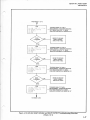
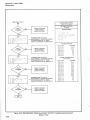
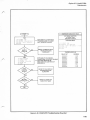
4-29. Each test in the diagnostic program has a corresponding troubleshooting flowchart .
With the troubleshooting flowcharts is a description that includes when and how to use them.
The names of the troubleshooting flowcharts correspond with the test in the diagnostic program
for easy reference . If the problem cannot be isolated by use of the troubleshooting flowchart,
the flowchart will lead to an ASM state table where troubleshooting will require evaluation of
ASM operation .
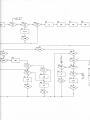
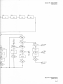
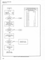
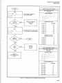
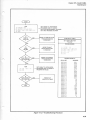
4-30. The overall ASM flowchart, included with a description, shows the possible ASM operational loops . Use it in conjunction with the ASM state tables, when troubleshooting, to determine what operation the ASM is performing during a given ASM address .
4-31 . The examples of basic ASM problems at the end of this section include identification
procedures and troubleshooting techniques .
4-32.
Option 011 Diagnostic Program
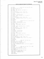
4-33. The diagnostic program in Table 4-5 is written for the 9830A Calculator and is designed
to completely test Option 011 . It is intended for use when the Option 011 either fails the performance test, local operation test, or the user feels that there is a problem with the interface
board, not found in the above stated tests.
4-34. If it is necessary to type the total diagnostic program into the 9830A memory, it is advisable to store the program on a cassette for possible future use. Refer to Hewlett-Packard
9830A Calculator, Simplified Operating Instructions, HP Part No. 09830-90000 for explanation
of cassette use .
4-35. LOADING THE PROGRAM . Prior to loading the program, push the STOP key down
until STOP appears on the display . If the display remains blank refer to 9830A Operating and
Programming Manual, Appendix A . Push the remaining keys to program the calculator as shown
in the printer list in Table 4-5 .
4-36. VERIFY THE PROGRAM . After the program has been loaded, push LIST and EXECUTE
keys. This will run a printer list of the program . Check the list to verify that the program was
entered correctly .
4-37. RUNNING THE PROGRAM . To run the program push the RUN and EXECUTE keys.
When the calculator display asks for a response, perform as requested then press CONT, then
press EXECUTE . If the display asks a question for which the answer is "no", answer by pressing N then pressing EXECUTE . The first part of the program, as shown in the printer list in
Table 4-5, consists of many tests. Each test has a subroutine number that follows the test title
in the list. Any single test can be performed by pressing CONT, typing the number next to the
specific test and the EXECUTE keys.
Option 011,Model S328
Maintenance
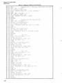
Table 4-5.
Diagnostic Program List
FORMAT 10B
) FORMAT F5 .0
DIM R$[10]Q$[
B$=^[ ^
50 DTSP ^5328A
60 WHIT 1500
70 DISP "SET LISTEN HI
STOP
REM :
TEST RNT/L|
00 GOSUB 5i0
0 REM :
GOSUB 660
R EM :
GOSUB 8&0
AND
REM :
TEST TALK
UNTH
GOSUB 900
REM :
TEST LISTEN AND UNLTSl
GOSUB 1040
| REV
:
TEST GET
200 GOSUB 1140
1 REM :
GOSUB 1200
10 REM :
TEST H[
240 GDSUA 13g0
250 REM :
TEST FN COVS, TB CODE, DP AND ~
0 GOSUB 1730
1 REM :
30 GOSUB 1910
D0 REM :
!0 GOSUB 2Q0 ;i~ :
|0 REM :
320 GOSUB 212(~)
330 REM :
TEST OD ;
40 GGSUB 222!;~J
0 REM :
TEST SAMPLE RATE
S0 GOSUB 228@
70 REM :
TEST HRMIN~
)0 COSUB 2440
) REM :
TEST STORAGE
400 GOSUB 2520
410 REM :
TEST
420 GOSUB 260i~i
430 REM :
440 GOSUB 275D
c T TF
450 REM :
460 GOSUB 282Q
470 REM :
T ADDRESS SW TTC!--!
480 GOSUA 2920
490 DTSP ^5328A HPIB INT . CHE[ K COMPLETEI
500 STOP
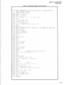
Option 011, Model 5328A
Maintenance
Table 4-5. Diagnostic Program List (Continued)
REM :
OUTP|
CM D
DISP
INPUT C$
OUNl
C$[11
OUNTER
P TOP
RETURN
REW
SUBRO
OUTPUT (13 ;10)768
OUTP|
[MD
DISP "PUSH REYE
STOP
DISP "DOES COUNT
INPUT Cli:
: POS(C01,1100)
;
SP ^LLO FAILS"
GOP
OUTP ;T
OUTPUT
DISP PUSH RESE
STOP
DISP ^DO[
INPUT
34U IF POS([$[191
850 DISP "COUNTER
860 STOP
870 RETURN
880 RE M :
890 [MD "?U9
^PF<(]
13, 10)206
900 OUTPi
]>1 THE
910 IF 8]
DTSP
INTERFHC[~
920
920 STOP
940 RETURN
950 REW:
UB
^
960 CMD ^?U9 97F
)T
970 OUTPUT 03 ;|&i
080 WRBYTE13
990 OUTPUT (130Y
l000 IF H=64 THEN 1030
1010 DISP "IMPROPER SRW
1020 STOP
1030 RETURN
4-9
Option 011, Model 5328A
Maintenance
1040
1@50
1060
1070
1080
1090
1100
1110
1120
1130
[40
50
S@
'0
A
190
[200
1210
|220
|230
1240
250
260
D
1290
|3QN
1310
1320
1330
1340
1350
1360
1370
\38Q
1390
1400
141@
1420
1430
144@
1450
1460
1470
1480
1490
1500
1510
52@
1530
1540
1550
1560
1570
158@
1590
1600
Table 4IDiagnostic Program List
REV
SUBROUTINE FO TESTING LISTEN AND UNLISTEN
[MD ^?U9^ ;^PF<G0T^
IF STHT1A2 THEN 1Q9~~j
DTSP "COUNTER DOES NOT LISTEN PROPERLY''
S TOP
[MD ^9U9^ :"PF<G0R",^9^5^T^
IF STHT|V\ THEN |130
DTSP "COUNTER DID NOT LISTEN''
ST0 1: :'
RETURN
REQ
SUBROUTINE FOR TESTING GET
[MD ^?UK,^PKGOR^,^
OUTPUT 03,10050
IF STHT13>1 THEN 1 ; i~!
DISP "TRIGGERS WHEN NOT
STOP ^9^
[MD
OUTPUT 03,10)256,8012
IF STHT13<I THEN 120~~i
DISP "COUNTER FAIL
RE6POND
STOP
RETURN
REM :
D
-- TEST
^" .,"
,mn
ynu ^'"m^
'up , ^oc'r",cr^
rr`uvow/
ENTER (13 ;0Z$
IF Z$115,151-'
DISP "NO [HEC!
STOP
OUTPUT (A,10)25
CMD ^?U9^,^S5^ ;^?V
ENTER 03 ;07$
IF 7$[|5,15]=^0^ THE!1
DISP `D[L DOES NOT WORK
STOP
RETURN
REQ
TES
^
^
CMD
9U9 ,04GO60''
ENTER (13 ;*)Z$
IF 0115051=0
DISP "NO CAECI K=
STOP
OUTPUT (13,100504,512 ;
^
CMD ?UX ;"S&
CMD ^?Y5 1 '
ENTER (13,071i:
ENTER (139*)7$
IF 7$[15 ;15]=^6^
DTSP "RESPONSE TO SDC WHE!
STOP
CMD ^K
OUTPUT (13,1005694,510;
CMD ^?U9^,^S5^,^?Y5^
ENTER (139*0$
IF 7015 ;151=1~!
DTSP "NO RESPONPF
STOP
RETURN
Option
oil,
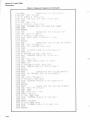
Table 4-5. Diagnostic Program List (Continued)
AND
161@ REM : SUAROUNTINE FOR TESTING TWFN [ODES,DP
ANNUNCIATOR READOUT
1620 CMD ^ ?X9 ^ 00 ^ 9YY
1630 ENTER (13 ;001i:
440 FOR I=1 T~
1650 IF POS(Z$[
660 NEXT I
,
~ ]=VHL(7$[K!~,
1 IF J-B^ THEN
) D7SP
7MPROPE
1 STOP
) RETURN
~ REM : SUBROUTINE FOR TESTING FNvTBCODES,DP AND ANN .
) FOR K-0 lU (
) H$=^PF<GO85T^
) OUTPUT
) H$[5 ;50P$[5 ;
) A=11-K
~ .
.1.
TV
"
i
.'i
n
GOSUB
i810 NEWT
1820 A=1 1
) GOSUB
A = 1~
BW~~
1610
G OSUB 161(
G
RETURN
REW
CMD
H=1 1
B = i~j
YJ 0:1
900
910
D20
930
IF n
1 j /l
DISP
FAIL
STOP
R ETLRN
REM :
CMD ^?U9^
ENTER K
IF DQF ;
1+G
DIM
A
950 STOP
960 CMID
]70 ENTER
980 IF
n
RETURN
UuMM
!U .-i
RESET 4 W.
Model 5328A
Maintenance
Option oil, Model S328
Maintenance
Table 4-5. Diagnostic Program List (Continued)
) REM :
3 0 CMD
STH
~ I F1
DISP ^[TR
X STOP
'0 CMD
| IF STHTI
^
2190 DISP "COUNTER WILL NOT MAKE MUiT MEHS
2200 STOP
2210 RETURN
0 REV
)0 CMH)
10 IF STHT13>1 THU .
j0 DISP ^HPTB DOES
STOP
0 RETURN
D REM :
SUBROUTINE FOR TESTING SK UUNINUI
V q @ [MD
D0 DISP "PUT COUNTER INTO HOLD
S T0 1:::~
DISP "IS ~
IN P XT 0$
IF POS(C$[1 ;1],8$) THEN
QO DISP "COUNTER
STOP
CM D
)80 DISP "DOES SHMPL
INPUT C$
IF POSQ$[1 ;1]9G$) THEN
DISP "SAMPLE RATE
20 STOP
3@ R E TURN
140 REM :
SUBROUTINE FOR TESTING HRMINC
DTSP "NO TRIGGER INTO CH B H!
STOP
2470 CMD ^? ;9^,^PF<GOS ;T^
2480 IF STHT13>\ THEN 251
ARM
2490 DISP "COUNTER FAILED
250@ STOP
25|0 RETURN
SUBROUTINE
2520 REV ;
FOR TESTING STO!
2530 CMD ^?U9^,^PF
2540 WATT 1Q0Q
^
^
2550 [MD
?UY, ~~
2560 ENTER (13,*)
2570 IF D#0 THEN
/!:::!
2580 DISP "STORAGE
AILED TO
2590 STDF:~
2600 ENTER (13,*)D1
2610 IF D1=D THEN 2640
2620 DISP "STORAGE FAII
2630 STOF::
2640 RETURN
Option
oil, Model
5328A
Maintenance
Table 4-5. Diagnostic Program List (Continued)
0 REM :
2690
2700
2710
2720
273@
274@
2750
2760
277@
2780
D
0
D00
2910
2920
)0
2950
2960
170WO~
0
:0
3040
3050
CM D
FOR 7Q,
CND ^?U9^
ENTER 03o,
IF D=I*1E+O7
DTSP "DE[ RE
Sl
NEW!
RET ;RI
REM :
CMD
ENTER
IF ZV~
ER F
S T0 P
RETURN
REM :
CMD
H TPU
DISP "TALK! HLWH
STOP
CMD ^?Y
ENTER (13,
DISP "TURN OH
STOP
RETURN
REW:
OUTPU
DTSP ^Silll
STOP
CMD ^?U4^ ;^ jw '
HQ
- -1
~mb
GOSXB 1(
DTSP ^SWI
STOP
OUTPUT (13,
^
CMD ?X*^
GOSUB 163@
RETURN
!1 HDDREE
403
Option 011, Model 5328A
Maintenance
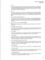
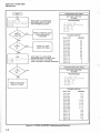
4-38 . PROGRAM DESCRIPTION . In the diagnostic program, A$ is used as the string variable
to program the counter. Z$ is the string variable that represents what the counter delivered as
output . After any test failure, these two strings may be examined showing what the counter was
programmed to and what it outputted . The following tests exercise the operations as described :
a.
Test REMOTE/LOCAL (RMT/LOC)
REN is sent true in line 520 of the program . The counter is addressed to listen in line
530. At this point it should go to remote . Line 590 turns REN false which returns the
counter to local.
b.
Test LOCAL LOCKOUT (LLO)
Line 680 programs LLO and 690 sends it into remote . At this point, pushing the counter
RESET button should not return the counter to local . Lines 770 and 780 cause REN to
go high and then low causing LLO to go off. The counLer then should go to local when
the RESET button is pushed .
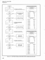
c.
Test GO TO LOCAL (GTL)
Statement 890 causes a service request while 900 causes the instrument to go to local,
disabling that request. If there is a service request it is assumed that the counter didn't
respond to GTL .
d.
Test TALK and UNTALK
The counter is programmed to service request and talk in lines 960 and 970 . If the
counter reads out a status byte of 64 it is talking correctly .
e.
Test LISTEN and UNLISTEN
The counter is programmed to service request and must listen correctly in order to do
so . In line 1090 it is instructed to unlisten before a trigger command . Not receiving a
service request from the counterwould signify correct response to the unlisten command .
f.
Test GROUP EXECUTE TRIGGER (GET)
The counter is prepared for a measurement but not triggered and unaddressed to listen
in line 1150 . The GET command is then sent . The counter must not respond to this since
the GET command is an addressed one . The counter is then addressed to listen and
should trigger, giving a service request.
g.
Test DEVICE CLEAR (DCL)
The counter is programmed for a standard "Check" measurement in line 1270 . In 1280,
the data output is received from the counter to see if it programmed correctly . DCL is
programmed in line 1320 . The counter is then told to read out on the fly (that is the only
way it will read out the string the second time) and the exponent digit is checked for
a "0" where it was a "6" before DCL was applied .
h.
Test SELECTED DEVICE CLEAR (SDC)
The test for SDC is the same as for DCL except the counter is also checked for not responding to SDC when not addressed in lines 1450 and 1520 .
i.
Test FUNCTION (FN), TIME BASE (TB), DECIMAL POINT (DP), and ANNUNCIATOR
READOUT
In this test "A" represents the position in the output string where the DP is expected
(A=4 fn DP on right of MSD, increasing to right) . The B represents the value of the exponent read out by the 5328A . In this test a series of function and time base code combinations are programmed and their output strings checked for proper DP position
and exponent value. This subroutine calls the one beginning at line 1610 which
actually checks to see if the A and B numbers are correct.
Option 011, Model 5328A
Maintenance
j.
Test "P"
In line 1920 an SRQ is generated and then cleared by the second "P" in the A$ string .
The counter is then checked to see if the Function code reset to STOP and Time Base
code to 0 and that SRQ was cleared. The command "P" sets the counter to a power
up reset state, the same as SDC and DCL .
k.
Test "R"
The counter is programmed to a normal check measurement in line 2010 . The reading
is then checked to be correct (nonzero) . "R" is then programmed in line 2060 and the
data output is then checked to be zero since "R" resets the DCA, Display, and Time
Base .
I.
Test MULTIPLE MEASUREMENTS (MLT)
m.
Test for not WAIT UNTIL ADDRESSED (ODU)
n.
Test SAMPLE RATE (SR) Control
o.
Test ARMING
p.
Test STORAGE
q.
Test DECADE RESET DISABLE and DIGIT OUT
r.
Line 2130 sets the counter to MLT true (S1) and the counter will make multiple measurements . Thus it checks to see that it is off by testing for no completed measurement.
MLT is then turned on in line 2170 and the counter is tested for triggering which it
should do .
ODU is tested by checking to see if SRQ is disabled when ODU is on (S3) . ODU disables SRQ.
The counter is put into maximum cycle mode (S13) first to see if the counter will cycle
rapidly . Then (S7) in line 2370 is also programmed causing the sample rate pot to work
and is tested by the user .
The counter is programmed to an armed check function in line 2470 when Channel B
arms the measurement. With B not triggering the counter should not trigger.
Storage is turned off on line 2530 for a check measurement with a long gate time . It is
then turned on again . Two samples of the data are read out and if they are the same
and not zero storage, on and off must have worked properly .
I n this test, 10 check measurements are made with Decade Reset Disable on . The measurement is set up in line 2660 . The triggering is done in 2680 . The reading is then
checked to increment by 10' each trigger .
Test OVERFLOW
The counter is made to overflow and a "0" is checked for in the leading output digit .
s.
Test TALK ALWAYS
t.
Test ADDRESS SWITCH
Putting the counter in talk always is similar to having it programmed to talk . Thus the
calculator looks for output from the counter without addressing it to talk .
Here different combinations of the addressed switch are set and the counter is checked
to respond to the corresponding address on the bus.
4- 1 5
Option 011, Model 5328A
Maintenance
4-39. USE OF THE DIAGNOSTIC PROGRAM .
as follows :
a.
When the diagnostic program is used proceed
The following equipment is needed to perform the diagnostic program :
Model
Model
Model
Model
9830A Calculator with Extended I/O ROM and String Variables ROM
9866A Printer
59405A HP-113 Calculator Interface (Option 030)
5328A Counter with Option 011 board under test
b.
Configure the equipment as outlined in paragraph 4-20. If the 9830A is not equipped
with Option 274, insert the String Variables ROM into one of the 9830A ROM slots.
c.
Set the 5328A Counter controls as follows :
FUNCTION . . . . . . .
FREQ RESOLUTION
SAMPLE RATE . . . . .
ARMING . . . . . . . . .
STORAGE . . . . . . . . .
OSCILLATOR . . . . .
TALK ALWAYS . . . .
ADDRESS . . . . . . . . .
. .
.
. .
. .
. .
. .
. .
. .
.
.
.
.
.
.
.
.
..
. .
. .
. .
. .
. .
. .
..
.
.
.
.
.
.
.
.
.
.
.
.
.
.
.
.
.
.
.
.
.
.
.
.
.
.
.
.
.
.
.
.
.
.
.
.
.
.
.
.
.
.
.
.
.
.
.
.
.
.
.
.
.
.
.
.
.
.
.
.
.
.
.
.
.
.
.
.
.
.
.
.
.
.
.
.
.
.
.
.
.
.
.
.
.
.
.
.
.
.
.
.
.
.
.
.
.
.
.
.
.
.
. . . . .
. . . . .
. . . . .
. . . . .
. . . . .
. . . ..
NOT
.. ....
. . . . . . CHECK
. . . . . . .1 kHz
. . . . . . . . CCW
. . . . . . . . . OFF
. . . . . . . . . . ON
. . . . . . . . . . INT
TALK ALWAYS
. . . . . . . . . . «9"
d.
Referring to paragraph 4-20, load the diagnostic program into the memory of the 9830A .
Verify the program as outlined in paragraph 4-23.
e.
To execute the diagnostic program, refer to paragraph 4-24, if the Option 011 under
test fails any test, the 9830A will display the failure mode and the program will stop.
The operator may continue the program by pressing the CONTINUE and the EXECUTE
keys. Successful completion of the diagnostic is confirmed by the 9830A displaying
"5328A HP-113 INT . CHECK COMPLETED" .
f.
If a board fails, and the 9830A displays the failure mode, refer to the diagnostic program
listing in Table 4-5 to find the test that contains the failure display statement . Once it
is determined which test the board failed, refer to the corresponding troubleshooting
flowchart to localize the failure .
4-40.
ASM Flowchart
4-41 . The ASM flowchart in Figure 4-1 shows all of the possible states that the ASM may
exercise . I n any given mode, program sequence, or output routine, the ASM may exercise some
states once or some states many times depending on the particular case.
4-42. Above each symbol are two numbers . The number above and to the right is the decimal
number equivalent, of the binary ASM address, that is present at the input of the ROM . The
address is present at pins 3, 4, 5, 14, 15, 25, 26, and 27 of the ROM, with the least-significantbit at pin 3. The number above and to the left of each symbol is the octal equivalent of that
state address . Both numbers are included for ease of service and troubleshooting .
4-43 . THE RECTANGLE . A rectangle symbol represents a process state . In this state, the
ASM causes some action to take place . As an example, in ASM address or state (octal) "6",
inhibit is set low by the ASM and associated circuitry . Also, while in the process state, the
Format Bit from the ROM (U22) is low assuring that the state counters will only increment the
ASM address by one count at the next positive clock pulse transition .
4-44. THE DIAMOND . A diamond shaped symbol represents a decision state. In a decision
state, the Format Bit from the ROM is set high allowing the state counters to either increment
by one count or parallel enable the jump state information from the output of the ROM as the
next ASM address information to the ROM input. The jump is executed if the qualifier associ4-1 6
Option 011, Model 5328A
Maintenance
ated with the state is high during the given ASM address. The jump is accomplished by the
ROM setting U30(8) to the high state. When U30(8) is set high, U30C will give the necessary
positive output required for the jump if the qualifier is high and the parallel enable will take
place at the next positive clock pulse transition . If the qualifier is low during the particular
ASM address, the state counters will increment the ASM address by one count.
4-45 . "N" DECISION STATE . If an "N" is in a decision symbol, the jump is executed if the
qualifier associated with the state is low during that ASM address. The jump, in this case, is
caused by the ROM setting U30(10) low. When U30(10) is low, U30C will give the necessary positive output required for a jump if the qualifier is low at the next positive clock pulse transition .
The state counters will increment the ASM address by one count, at the next positive clock
pulse transition, in an "N" decision state if the associated qualifier is high .
4-46 . THE CIRCLE . A circle symbol at the end of a flow line, indicates the line is continued
at another such symbol on the sheet.
4-47.
Troubleshooting Flowcharts
4-48 . The troubleshooting flowcharts included in Figures 4-2 through 4-22 are provided
for failure isolation . They will either lead directly to the problem, or require evaluation of
ASM operation to isolate the problem .
4-49 . Included with most of the troubleshooting flowcharts (whenever ASM operation must be
evaluated) are ASM state tables . The state tables contain programming information, logic
state analyzer control settings, and expected results needed to analyze ASM operation in the
given mode of operation .
4-50 . Whenever the troubleshooting flowchart calls for PGM (program), first press the STOP
and EXECUTE then press the SCRATCH and EXECUTE keys on the 9830A Calculator . This
will clear the memory and allow the operator to enter the new program.
4-51 . When the memory is clear, type the program information supplied, into the memory of
the 9830A Calculator, and execute the program by pressing the RUN and EXECUTE keys . After
executing the program if the troubleshooting flowchart asks a question (decision state) stop
and check for the condition.
4-52 . To check the condition of STAT 13, which indicates the status of the Bus, type STAT
13= on the 9830A Calculator and then press the EXECUTE key. The 9830A will either display
0, 1, 2, or 3. A "0" or "1" condition indicates the 5328A has vompleted a measurement . A
"2" or "3" condition indicates the 5328A has not completed a measurement. For further explanation of STAT 13, refer to Hewlett-Packard Interface Bus Users Guide 9830A, HP Part
No . 59300-90002.
4-53 .
ASM Troubleshooting
4-54 . If an Option 011 fails a test in the diagnostic program and the troubleshooting flowchart
for that test leads to an ASM state table, then it is necessary to troubleshoot the board by
evaluating the ASM with a logic state analzyer .
4-55 . The following paragraphs describe how to use a logic state analyzer and the ASM state
tables to locate problems on an Option 011 board .
4-56 . SYSTEM CONFIGURATION AND USE .
a given mode, proceed as follows :
To troubleshoot by ASM flow evaluation, in
Option 011, Model 5328A
Maintenance
a.
The following equipment is needed to troubleshoot the ASM :
Model
Model
Model
Model
Model
9830A Calculator with Extended I/O ROM
9866A Printer
59405A HP-113 Calculator Interface (Option 030)
HP 180A Oscilloscope with HP 1601 Logic State Analyzer
5328A Counter with Option 011 under test
b.
Connect the 9830A Calculator with Extended I/O ROM, the 9866A Printer, and the 5328A
Counter with Option 011 under test as outlined in paragraph 4-20.
c.
Insert the HP 1601 Logic State Analyzer into the HP 180A Oscilloscope and connect to
5328A as follows :
1.
Remove 5328A top cover .
2.
Connect 10230A Clock Probe to U14 Pin 2 and common to U14 Pin 8.
3.
Connect the 10231A Six-Bit Probes as follows :
Bit
Bit
Bit
Bit
Bit
Bit
Bit
Bit
4.
to
to
to
to
to
to
to
to
U14
U14
U14
U14
U23
U23
U23
U23
Pin
Pin
Pin
Pin
Pin
Pin
Pin
Pin
14
13
12
11
14
13
12
11
Set the controls on the 1601A Logic State Analyzer as follows :
DISPLAY
LOGIC . . . . . . . . .
MARK . . . . . . . . . .
BYTE . . . . . . . . . . .
THRESHOLD . . . . . . . .
CLOCK . . . . . . . . . . . . .
DISPLAY TIME . . . . . .
COLUMN BLANKING
DELAY SET . . . . . . . . . .
TRIGGER MODE . . . .
SAMPLE MODE . . . . .
TRIGGER WORD . . . .
4-1 8
0
1
2
3
4
5
6
7
.
.
.
.
.
.
.
.
.
.
.
.
.
.
.
.
.
.
.
.
.
.
.
.
.
.
.
.
.
.
.
.
.
.
.
.
.
.
.
.
.
.
.
.
.
.
.
.
.
.
.
.
.
.
.
.
.
.
.
.
.
.
.
.
.
.
.
.
.
.
.
.
.
.
.
.
.
.
.
.
.
.
.
.
.
.
.
.
.
.
.
.
.
.
.
.
.
.
.
.
.
.
.
.
.
.
.
.
.
.
.
.
.
.
.
.
.
.
.
.
.
.
.
.
.
.
.
.
.
.
.
.
.
.
.
.
.
.
.
.
.
.
.
.
.
.
.
.
.
.
.
.
.
. . . . . . . . . . . . . . . . . POS
. . . . . . . . . . . . . . . . . OFF
. . . . . . . . . . . . . . . 3 BIT
. . . . . . . . . . . . . . . . . TTL
. ... . . . ... .........
. . . . . . . . . . . . . . . . CCW
. . . . . . . . . . . . . . . . CCW
..............
00000
. . . . . . . . START DELAY
. . . . . . . . . . . . . . . REPET
Set Switches 0-7 to 003,
Switches 8-11 to OFF
d.
With all of the equipment turned on, the HP 180A Oscilloscope should display bit patterns on the display . To assure this, set the 5328A Function to STOP and make sure it
is in local operation . If the oscilloscope is not displaying bit patterns, refer to example 1
paragraph 4-56 to locate the problem .
e.
When a specific test is failed and the troubleshooting flowchart leads the user to the
ASM state table proceed as follows :
1.
Use the information in the ASM state table to set controls differently than in
paragraph 4-39c.
2.
If programming information is supplied in the state table, enter the program
into the 9830A and RUN the program .
3.
Set the analyzers TRIGGER WORD to agree with the "trigger word" in the ASM
state table.
4.
The top line (bits of information) of the analyzer display will be the octal representation of the trigger word .
Option 011, Model 5328A
Maintenance
5.
Increment the DELAY SET switch by one count and check the analyzer display .
The top line should be the octal equivalent of the number listed next to the
corresponding delay setting in the state table .
6.
Continue step 5 until the entire ASM state table is verified or the problem is
determined.
4-57. BASIC ASM PROBLEMS . There are several possible ASM problems. In the following
paragraphs, a description of the problem, how to identify the problem, and troubleshooting
techniques will be given for some common problems .
4-58. Example 1: State Counters will not Increment .
state counters U14 and U23 will not up-count .
In a no increment failure mode, the
4-59. The problem will be discovered when the diagnostic,)rogram is used . When the program
is started, the display, on the 9830A Calculator, will blank and the program will stop .
4-60 . With this problem first make sure that clock pulses are present at U14(2) and U23(2) .
The clock pulse check can be made in two ways . The first, a quick check, can be made if the
logic state analyzer is connected . This check is accomplished by observing the "NO CLOCK"
lights on the logic state analyzer. If either light is on, the analyzer is indicating that there are
no clock pulses present and shows the condition (high or low) of the clock input. The second
method is to use a standard oscilloscope on U14(2) or U23(2) .
4-61 . If clock pulses are present, remove the ROM U22 and check the logic state analyzer
(as connected in paragraph 4-56c., to make certain the state counters are up-counting correctly . To check the state counters for proper up-counting, trigger the logic state analyzer on
TRIGGER WORD "0" (all switches 0-7 to low position) with the other controls set as outlined
in paragraph 4-56c . The analyzer should be displaying binary state address "0" on the top
line of the display . As the DELAY SWITCH on the analyzer is increased by one number, the top
line, ASM address, of the display should increase by one number (decimal) until decimal 255
appears, and the count sequence starts over .
4-62. Example 2: ASM Jumps Only. In a jump only failure mode, the state counters always
parallel enable the ROM's output jump information as the next ASM address .
4-63 . When the diagnostic program is used, the jump only problem will be discovered . The
Option 011 will fail a test in the diagnostic program . The test failed will lead to the troubleshooting flowchart associated with the test, and the flowchart will lead to use of the ASM state
table, where it will be necessary to evaluate the ASM flow in the particular mode.
4-64. After the logic state analyzer is connected, as in paragraph 4-56c., and the analyzer
TRIGGER WORD is set to the ASM state table requirement, observe the display on the logic
state analyzer. The pattern on the display will not agree with the ASM state table addresses .
A close evaluation of the ASM flow will show that, in every decision state, the ASM executes
a jump to a new address .
4-65. To further evaluate the problem, take data bit probe number eight (on the logic state
analyzer), isolated with a 100051 resistor, and connect it to U25(3) . Set the number 8 trigger
word switch to the off position . If the display, on the analyzer, in column eight is always low,
check U25 and associated circuitry (it may be necessary to use a standard oscilloscope to
assure that waveforms go to both logic levels) . U25(3) should only be low during an ASM
decision state, with the proper qualifier condition .
4-66. Use of data bit probe number eight with the 100011 isolation is a powerful aid . It may
be used to help isolate problems at a certain ASM address state .
Option 011, Model 5328A
Maintenance
4-67. Example 3: ASM will not jump. In a no jump failure mode, the new or next state ASM
address (decimal) always increases by only one count .
4-68. This problem will be discovered when the diagnostic program is used . After the test
failed leads the user to a troubleshooting flowchart, the flowchart will lead to use of the ASM
state table and the logic state analyzer. When the analyzer is connected (refer to paragraph
4-54c .), the pattern on the display will not match the ASM addresses in the state table, each
next state address will be incremented by one count only.
4-69 . To troubleshoot the problem, find an ASM address in the ASM state table where the
next ASM address (decimal) is increased by more than one count . Using this ASM address
and data probe number 8 as explained in example 2, check U25(1) at the ASM address . At this
and all decision state addresses, U25(1) must be high.
4-70 . Referencing to the same ASM address, check U25(2) with data probe 8 . It also should
be high at the ASM address . If U25(2) is low, check U30(9,10) with the data probe . Pins 9 and
10 must be of different logic states during the ASM address if the jump is to take place .
4-71. Example 4: ASM will not jump due to Improper Qualifier . Unlike example 3, where
the problem was within the ASM itself, this example is where the associated qualifier, for the
state in question, is of the wrong condition .
4-72. If the wrong qualifier is received, the problem will be recognized by use of the diagnostic program . When the diagnostic program is used, the particular interface will fail a
test . The troubleshooting flowchart will lead to use of the ASM state table .
4-73 . This failure mode is different than example 3 . The difference is, that in all decision
states in example 3 the ASM did not jump. In this example, the ASM will jump in some decision
states .
4-74. To locate the problem, compare the display on the analyzer against the ASM state
table for the test in question . The error will always be spotted in a decision state. Even if the
interface fails to perform a process state function (i.e., set listen low), it will not be noticed
until the ASM "looks" at the listen bit in a decision state.
4-75 . The method of using data bit probe number 8 (refer to paragraph 4-65), is useful to
check the qualifier bit in a decision state, and also useful to make sure a process state is causing the proper action.
4-76 . After comparing the display on the analzyer against the ASM state table an incorrect
decision state move will be found . Check the qualifier for the decision state in question by
using data bit probe number 8. If the qualifier is correct for the jump, and the jump does not
take place, follow the path that the qualifier takes to arrive at U30C(9) to locate the error . If
the qualifier is incorrect, and generated by the ASM (in a process state), check to see if the
ASM flow in the particular mode exercises the process state in question . It may be checked
by the data bit probe method .
Option 011, Model 5328A
Maintenance
Table 4-6 . 5328A Option 011 Signal Mnemonics
QUALIFIERS
Signal
Description
Source
ADDR
ANN
ATN
U26(4)
U32(3)
U8(5)
H = My Listen Address
L = Annunciator On
L = Attention
B0
131
B2
B3
BLK
U12(5)
U12(6)
U12(7)
U12(9)
U6(7)
16
16
16
16
D
DAC
DAV
D101
D102
D103
D104
D105
D106
D107
U32(5)
U8(7)
U3(1)
U3(2)
U3(3)
U3(4)
U3(5)
U3(6)
U3(7)
U3(9)
H = Decimal Point has been Outputted
H = Data Accepted
L = Data is Valid
HP-113 Data Bit 1
HP-113 Data Bit 2
HP-IB Data Bit 3
HP-IB Data Bit 4
HP-113 Data Bit 5
HP-IB Data Bit 6
HP-113 Data Bit 7
EOM
U8(1)
H = End of Measurement
i
U8(2)
Always HIGH, used for unconditional Jump
LDP
LIS
LLO
U32(2)
U6(1)
U19(9)
L = Decimal Point On
H =Address to Listen
H = Local Lockout On
MA
U6(5)
MB
U6(6)
MLT
MS
U32(6)
U29(3)
L = Enable Strobe to Function Select Latch U34 and Select Bit on
Module Strobe Code
L = Enable Strobe to Time Base Select Latch U28 and Select Bit on
Module Strobe Code
H = Make Multiple Measurements
H = Module Strobe L = FC & TB Strobe
OVFL
ODV
U32(4)
U32(7)
L = Overflow
L = Wait until Addressed
RDF
REN
RFD
RMT
U32(9)
U8(4)
U8(9)
H = Read Data on the fly
L = Remote Enabled
H = Ready for Data
H = Option 011 in Remote
S
SP
SRQ
SWL
U32(1)
U32(1)
U6(3)
U8(6)
H = Measurement has dimension of time
H = Serial Pole Active
L = Service Request
H = Switch to Local
TALK A
TLK
U6(2)
U26(5)
L = Talk Always
H = Address to Talk
State
State
State
State
Sequence
Sequence
Sequence
Sequence
Count
Count
Count
Count
for
for
for
for
Output
Output
Output
Output
of
of
of
of
ASCII
ASCII
ASCII
ASCII
Code
Code
Code
Code
Option 011, Model 5328A
Maintenance
Table 4-6 . 5328A Option 011 Signal Mnemonics (Continued)
OUTPUTS
Signal
LLIS
HLIS
LTLK
HTLK
LSP
HSP
LMA
HMA
LS
HS
HLTCH
LRMT
HRMT
LD
HD
LMB
HMB
LMS
HMS
LDAV
HDAV
LRFD
HRFD
LDAC
HDAC
LLO
HLLO
LEOM
HIC
HDSA
LRPR
HRPR
LDDIS
HDDIS
LINH
LRST
HRST
LSRQ
HSRQ
ASP
LDAO
HDAO
ADIG
ALF
A0
ACR
AE
ADP
A3
A6
A9
A+
AAOVF
4- 2 2
Source
Description
Unlisten
Listen
U ntalk
Talk
Serial Poll Disable
Serial Poll Enable
Enable Function Code Latch Input Module Select Code . Also used
in putting out Exponent
Opposite of LMA
Measurement does not have dimension of time . Output POS EXP
Opposite of LS
Latch Data into U28, U33, or U34
Go to Local
Go to Remote
Decimal Point has not been outputted
Decimal Point has been outputted
Enable Time Base Code Latch input, Module Select Code . Also used
in putting out Exponent
Opposite of LMB
Enable Function and Time Base Code Latches Disable Module
Strobe Line
Opposite of LMS
5328A says Data Not Valid
5328A says Data Valid
5328A says Not Ready for Data
5328A says Ready for Data
5328A says Data not Accepted
5328A says Data Accepted
Local Lockout Off
Local Lockout On
Reset End of Measurement F/F (U11B)
Initialize 16 State Counter
Strobe Mainframe Display and 16 State Counter
Turn OFF Master Remote Programming Reset
Turn ON Master Remote Programming Reset
Low Disable Display . TTL active low turns blanks display except
LHS Annunciators
Opposite of HDDIS
Inhibit Counter from Arming
Turn OFF Counter Mainframe Reset
Turn ON Counter Mainframe Reset
Output (on U15, U24) Binary 0 on ASCII Bus
Output (on U15, U24) Binary 64 on ASCII Bus
Output (on U15, U24) ASCII space
Output (on U15, U24) all HIGHS on Bus and Disarm DAC Line
Output (on U15, U24) all HIGHS on Bus and Arm DAC Line
All succeeding bits put out on U15, U24 to be put on HP-113
as ASCII Characters
ASCII Digit from Display
ASCII Line Feed
ASCII 0
ASCII Carriage Return
ASCII E
ASCII Decimal Point
ASCII 3
ASCI 16
ASCII 9
ASCII +
ASCII ASCII Letter O
12
SH Is
TH .2
TO
327
SH .3
Option 011, Model 5328A
Maintenance
102
FROM
371
SH .2
147
TO 206
SH .2
TO 153
SH .2
Figure 4-1 . ASM Flowchart
(Sheet 1 of 3)
4-23
FROM
152
$H . I
153
0
0
154
155
156
L
0
165
164
FROM
137
SH .I
FROM
152
SH .I
0
153
273
Option o11, Model 5328A
Maintenance
TO 7
SH .I
Is
imp
301
207
FROM
152
SH .I
210
TO 123
SH .I
Figure 4-1 . ASM Flowchart
(Sheet 2 of 3)
4-25
FROM
126
SH .I
TO 17
SH .I
332
LRFD
ATN
N
1
0
333
DI07
N
340
337
336
I
0
DI06
N
LS
341
342
LMS
i--i
HMA
HMB
334
HLTCH
335
JUMP
q
O
343
DI05
1
363
344
I
DI04
p
345
DI03
0
0
TO
T6
SH .I
346
HMS
DI04
364
DI03
M
347
DI02
I
366
0
350
353
DI01
DI01
Np
I
354
351
LMB
DIOI
N
HS
0
372
370
<
DI02
N
I
375
I
I
K
o
T
376
73
SH .I
I
HDDIS
377
LMA
JUMP
365
371
JUMP
355
0
374
0
0
367
0
LMB
352
I
1
DI01
N
I
373
JUMP
356
JUMP
<
Option 011, Model 5328A
Maintenance
TO T5
SH .I
FROM
31
SH .I
TO 124
SH .I
Figure 4-1. ASM Flowchart
(Sheet 3 of 3)
4-27
Option 011, Model 5328A
Maintenance
SET 5328A
FUNCTION . . . . . . . . CHK
FREQ RES . . . . . . . N=106
SAMPLE RATE . . . . CCW
DISCONNECT HP-113
CABLE FROM 011
TURN 5328A POWER
SWITCH TO STBY THEN
TO ON
DISCONNECT ONE
END OF 28-CONDUCTOR
CABLE
Figure 4-2. Local Troubleshooting Flowchart
4-28
Option 011, Model 5328A
Maintenance
START
REMOTE ASM STATE TABLE
PGM
SET 5328A FUNCTION
TO STOP
PROGRAM 9830A
SETS 5328A to REMOTE
AND LISTEN MODE
NO
REFER TO REMOTE
ASM STATE
TABLE
YES
PGM
..I . .
I!
:
:
:
,
ii : i'
SETS REN HIGH, CAUSES 5328A
TO RETURN TO LOCAL MODE
i. I::ais
TRIGGER WORD 050
DELAY SET
0
0
0
0
0
0
0
0
0
0
0
0
0
0
0
0
0
0
0
0
0
0
0
0
0
0
0
0
0
0
0
0
0
0
0
0
0
1
2
3
4
5
6
7
8
ADDRESS
5
5
5
5
3
3
1 4
1 4
1 4
0
1
2
3
4
5
0
1
4
CHANGE TRIGGER
WORD SET TO 003
00000
000 0 1
000 0 2
00 0 0 3
00 0 0 4
0 0 0 0 5
0 0 0 0 6
NO
YES
YES
NO
SUSPECT
U29, U9,
OR U6
1
1
1
1
3
4
7
0
3
4
5
LOCAL ASM STATE TABLE
SET 5328A FUNCTION
TO STOP
PROGRAM 9830A
REFER TO
LOCAL ASM STATE
TABLE
TRIGGER WORD 003
DELAY SET
0 0 0 0 0
00001
00002
00003
0 0004
0 0005
0000 6
00 0 0 7
00008
00 0 0 9
ADDRESS
3
5
6
7
1 0
1 1
1 2
1 3
14
1 5
Figure 4-3 . Remote/Local Troubleshooting Flowchart
4-29
Option 011, Model 5328A
Maintenance
START
PGM
la E':I
~::I i ;a
-
SETS 5328A TO LISTEN MODE
I :I I :Ci
PGM
i :1 ; ; .!-1 : :,1..1!
.
;.
.,
! . 1 :1 ;
LLO ASM STATE TABLE
:'
SET 5328A FUNCTION
TO STOP
PROGRAM 9830A
,!
ON :i!
.~. ! .
1:1!.1 j,, :.!
!
TRIGGER WORD 021
DELAY SET
ADDRESS
0 0 0 0 0
0 0 0 0 1
0 0 0 0 2
0 0 0 0 3
00004
0 0 0 0 5
0 0 0 0 6
0 0 0 07
0 0 0 0 8
0 0 0 0 9
0 0 0 1 0
0 0 0 1 1
0 0 0 1 2
0 0 0 1 3
0 0 0 1 4
2 1
2 2
2 3
2 4
25
2 6
5 4
5 5
6 1
6 2
3 4
3 5
3 6
3 7
3
Digitally signed by
http ://www .aa4df .co m
Figure
4-30
4-4 . LLO
Troubleshooting
Flowchart
Option 011, Model 5328A
Maintenance
START
- SETS 5328A TO LISTEN MODE
PGM
SENDS GTL COMMAND
- CAUSING 5328A TO RETURN
TO LOCAL OPERATION
GTL ASM STATE TABLE
SET 5328A FUNCTION
TO STOP
PROGRAM 9830A
TRIGGER WORD 021
DELAY SET
ADDRESS
0 0 0 0 0
0 0 0 0 1
0 0 0 0 2
0 0 0 0 3
0 0 0 0 4
0 0 0 0 5
0 0 0 0 6
0 0 0 0 7
00008
0 0 0 0 9
0 0 0 1 0
00011
0 0 0 1 2
00013
0 0 0 1 4
0 0 0 1 5
00016
2 1
2 2
2 3
2 4
2 5
2 6
5 4
5 5
56
5 7
6 0
34
3 5
36
3 7
3
5
Figure 4-5 . GTL Troubleshooting Flowchart
4-3 1
Option 011, Model 5328A
Maintenance
SETS 5328A TO LISTEN MODE;
- PROGRAMS 5328A TO CHECK AND
TRIGGERS COUNTER
REFER TO
LISTEN/UNLISTEN
TROUBLESHOOTING
FLOWCHART
SETS 5328A TO TALK MODE ;
TRANSFERS READING FROM 5328A
INTO 9830A REGISTER "Z$" ;
9830A DISPLAYS CONTENTS OF "Z$"
REFER TO SINGLE
CHARACTER
OUTPUT PROGRAM
BELOW
PGM
SINGLE CHARACTER
OUTPUT PROGRAM
NOTE
To check the output string one character at a
time, load the 9830A with this program . Press
the RUN and EXECUTE keys of the 9830A . The
9830A will display the first character of the
string in decimal form . Compare the format
and results by looking in Hewlett-Packard Interface Bus Users Guide 9830A Appendix B for the
conversion . Press CONT and EXECUTE keys
once and check the next character in the output string . Continue until the fault is located or
the complete output string is verified .
Figure 4-6. TALKIUNTALK Troubleshooting Flowchart (Sheet 1 of 2)
4-32
Option 011, Model 5328A
Maintenance
TALK ASM STATE TABLE
SET 5328A FUNCTION
TO STOP
PROGRAM 9WOA
;Q PORNHT
[01[]:
40 CMD "Y''
60 EN 1)
TRIGGER WORD 021
DELAY SET
ADDRESS
uwTALuAGM STATE TABLE
SET 5328A FUNCTION
TO STOP
PROGRAM 9830A
!M!
30
40
50
60
lUl : : : :
OUTPUT (13,10)76E
CMD "?U9^,^PF<G0T^
OUTPUT (13,10056,
GOTO 40
END
TRIGGER WORD 021
Figure
DELAY SET
ADDRESS
00000
00001
00002
00003
00004
00005
00000
O0007
00008
00008
00010
21
22
42
48
52
53
34
35
30
37
3
4-6 T4LK/UNTALK
Troubleshooting Flowchart (Sheet 2of2)
4- 3 3
Option 011, Model 5328A
Maintenance
LISTEN ASM STATE TABLE
SET 5328A FUNCTION
TO STOP
PGM
FURNHT 10P
OUTPUT (K ; i
.
.
J
1 )
FW0
1j qq (
SETS 5328A TO LI§TEN MODE ;
PROGRAMS 5328A TO CHECK
AND TRIGGERS COUNTER
REFER TO REMOTE/LOCAL
TROUBLESHOOTING
FLOWCHART
SETS 5328A TO LISTEN MODE ;
PROGRAMS 5328A TO CHECK, AND
RESETS COUNTER ; UNLISTENS
53RA, AND SENDS TRIGGER COMMAND
PROGRAM 9830A
, 1 1. v l ;
20 OUTPUT (13910760
30 CMD
60 410
TRIGGER WORD 021
ADDRESS
DELAY SET
0 0 0 0 0
00001
0 0 0 0 2
00003
00004
00005
00006
0 0 0 0 7
00008
0 0 0 0 9
00010
00011
00012
00013
0 0 0 1 4
2
2
2
4
5
5
5
5
3
3
3
3
1
2
3
7
0
1
2
3
4
5
6
7
3
4
7
UNLISTEN ASM STATE TABLE
SET 5328A FUNCTION
TO STOP
PROGRAM 9830A
30
40
50
60
CMD "?U9''
CMD
GOTO &:~J
E HI)
TRIGGER WORD 021
DELAY SET
ADDRESS
00000
00001
00002
00003
00004
00005
00006
00007
00008
00009
2 1
2 2
2 3
4 7
104
105
106
107
110
111
4 5
4 6
3 4
3 5
3 6
3 7
3
00010
0 0 0 1 1
00012
00013
00014
00015
00016
Figure 4-7 . LISTENIUNLISTEN Troubleshooting Flowchart
4- 3 4
Option 011, Model 5328A
Maintenance
10
20
30
40
PGM
GET ASM STATE TABLE
SETS 5328A TO
LISTEN MODE;
PROGRAMS CHECK
AND RESETS COUNTER
FORMAT 1013
OUTPUT (13,10)76G~
CMD ^?U9^,^PF<G0R"
END
REFER TO REMOTE/LOCAL
TROUBLESHOOTING
FLOWCHART
NO
SET 5328A FUNCTION
TO STOP
PROGRAM 9830A
40 OUTPUT (13,10)256 ;
50 OUTPUT (130OW ;
60 GOTO 5D
YES
PGM
TRUGER WORD 021
10 CMD
20 END
---umuaTEwunnuaA
NO
DELAY SET
ADDRESS
REFER TO
uSTsm/umuSTsm
TROUBLESHOOTING
FLOWCHART
YES
PGM
10 FORMAT
~0 OUTPUT
30 END
10B
(13,10)256"
- SENDS GET COMMAND
NO
REFER TO GET
ASM STATE TABLE
YES
10 FORMAT
20 OUTPUT
30 END
PGM
SETS 5328A TO LISTEN MODE ;
SENDS GET COMMAND
10E:
(13,10056 .57
YES
REFER TO GET
ASM STATE TABLE
NO
END
E
Figure 4-8 . GET Troubleshooting Flowchart
4-35
Option 011, Model 5328A
Maintenance
DCL ASM STATE TABLE
START
f E'p :,i . .~,
PGM
L i71
SETS 5328A TO LISTEN MODE;
_ PROGRAMS 5328A TO CHECK,
OUTPUT WHEN ADDRESSED,
AND TRIGGERS COUNTER
.4V; -,
F : : t" I :fi
NO
E: I'I :Ei
Ia: I ".i :Ia
TRIGGER WORD 021
DELAY SET
SETS 5328A INTO TALK MODE ;
_CAUSES 5328A TO OUTPUT READING
INTO 9830A REGISTER Z$ ;
9830A DISPLAYS CONTENTS OF Z$
NO
YES
PROGRAM 9830A
REFER TO REMOTE/LOCAL
TROUBLESHOOTING
FLOWCHART
YES
PGM
SET 5328A FUNCTION
TO STOP
REFER TO TALK/UNTALK
TROUBLESHOOTING
FLOWCHART
SENDS DECADE CLEAR; SETS 5328A TO
LISTEN MODE ; PROGRAMS 5328A TO
OUTPUT WHEN ADDRESSED; PLACES
- 5328A IN TALK MODE ; CAUSES
5328A TO OUTPUT READING INTO
9830A REGISTER Z$ ; 9830A DISPLAYS
CONTENTS OF Z$
0
0
0
0
0
0
0
0
0
0
0
0
0
0
0
0
0
0
0
0
0
0
Figure 4-9. DCL Troubleshooting Flowchart
4-36
0
0
0
0
0
0
0
0
0
0
0
0
0
0
0
0
0
0
0
0
0
0
0
0
0
0
0
0
0
0
0
0
0
0
0
0
0
0
0
0
0
0
0
0
0
0
0
0
0
0
0
0
0
0
1
1
1
1
1
1
1
1
1
1
2
2
0
1
2
3
4
5
6
7
8
9
0
1
2
3
4
5
6
7
8
9
0
1
ADDRESS
1
1
1
1
2
2
2
2
2
6
6
7
7
7
7
7
7
0
0
0
0
3
3
3
3
1
2
3
4
5
6
7
0
3
4
5
6
7
0
1
2
3
4
5
6
7
3
Option 011, Model 5328A
Maintenance
START
SDC ASM STATE TABLE
SET 5328A FUNCTION
TO STOP
PG M
1.14.,
11.11 .1'1 i:DI. I 1
4
I :I'1 :11
PROGRAM 9830A
SETS 5328A TO LISTEN MODE ; PROGRAMS
- 5328A TO CHECK, OUTPUT WHEN
ADDRESSED, AND TRIGGERS COUNTER
'.IIis
II
f1l1...111
II"~
'i . ..laI
NO
REFER TO REMOTE/LOCAL
TROUBLESHOOTING
FLOWCHART
PG M
Ij
I ;:
[: fill
I,I i
1:
hill
I
DELAY SET
SETS 5328A TO TALK MODE ; TRANSFERS
5328A READING INTO 9830A REGISTER
Z$ ; 9380A DISPLAYS CONTENTS OF
REGISTER "Z$"
I I
i 1 ;:: : I I .' Ell :I
f-l :,l11r l ..f .
1! 11: ::, 111
I I
"i.1
L :I' :
I1:r
I
, _.
TRIGGER WORD 021
YES
l i:11
i
I
SENDS SELECTED DEVICE CLEAR;
_ TRANSFERS 5328A READING INTO 9830A
REGISTER Z$ ; 9830A DISPLAYS CONTENTS
OF REGISTER Z$
NO
0 0 0 00
00001
0 0 0 02
0 00 0 3
0 00 0 4
00005
00006
0 00 0 7
00008
0 00 0 9
0 0 0 1 0
0 0 0 1 1
00012
00013
0 0 0 1 4
0 0 0 1 5
0 0 0 1 6
0 0 0 1 7
00018
00 0 1 9
0 0 0 2 0
0 0 0 2 1
00022
ADDRESS
1
1
1
1
2 1
22
2 3
2 4
2 5
66
67
7 0
71
7 3
7 4
7 5
76
77
0 0
0 1
0 2
0 3
34
3 5
3 6
3 7
3
REFER TO
LISTEN/UNLISTEN
TROUBLESHOOING
FLOWCHART
YES
PGM
.
X11
1::r1:j~?f'1(I,1
11;9
I:: f'i .[i
..1.
.,1 . .
1,11,1 .1::,1
q
a
.1. .1
cS4j I:: : .tla..l
:1.1.111::1
P
Figure 4-10. SDC
Troubleshooting Flowchart
4-37
Option 011, Model 5328A
Maintenance
FUNCTION CODE ASM STATE TABLE
SET 5328A FUNCTION
TO STOP
PROGRAM 9830A
SETS 5328A TO LISTEN MODE,
PROGRAMS 5328A FUNCTION CODE OF 15
TRIGGER WORD 334
REFER TO REMOTE/LOCAL
TROUBLESHOOTING
FLOWCHART
DELAY SET
ADDRESS
0 0 0 0 0
00001
0 0 0 0 2
0 0 0 0 3
0 0 0 0 4
00005
0 0 0 0 6
3 3 4
335
3 4
3 5
3 6
37
3
CHANGE TRIGGER WORD
SET TO 337
SETS 5328A TO LISTEN MODE;
- PROGRAMS 5328A FUNCTION
CODE TO Q
- SETS 5328A TO LISTEN MODE ;
PROGRAMS TIME BASE CODE TO 7
DELAY SET
ADDRESS
0 0 0 0 0
0 0 0 0 1
0 0 0 0 2
0 0 0 0 3
00004
0 0 0 0 5
0 0 0 0 6
0 0 0 0 7
0 0 0 0 8
0 0 0 0 9
0 0 0 1 0
0 0 0 1 1
0 0 0 1 2
0 0 0 1 3
0 0 0 1 4
0 0 0 1 5
3 3 7
3 4 0
3 4 1
3 4 2
343
3 4 4
3 4 5
3 5 7
3 5 0
3 5 5
3 5 6
3 4
3 5
3 6
3 7
3
TIME BASE CODE ASM STATE TABLE
SET 5328A FUNCTION
TO STOP
PROGRAM 9830A
TRIGGER WORD 334
DELAY SET
_ SETS 5328A to LISTEN MODE ;
PROGRAMS TIME BASE CODE TO Q
0
0
0
0
0
0
0
0
0
0
0
0
0
0
0
0
0
0
0
0
0
0
0
0
0
0
0
0
0
1
2
3
4
5
6
ADDRESS
3 3 4
3 3 5
3 4
3 5
3 6
3 7
3
CHANGE TRIGGER WORD
SET TO 337
DELAY SET
ADDRESS
0 0 0 0 0
0 0 0 0 1
0 0 0 0 2
00003
0 0 0 0 4
00005
0 0 0 0 6
0 0 0 0 7
0 0 0 0 8
0 0 0 0 9
0 0 0 1 0
00011
00012
0 0 0 1 3
0 0 0 1 4
0 0 0 1 5
3 3 7
3 4 0
3 4 1
342
3 4 3
344
3 4 5
3 5 7
3 5 0
3 5 1
3 5 2
34
35
3 6
3 7
3
Figure 4-11 . FUNCTION CODE and TIME BASE CODE Troubleshooting Flowchart
4-38
Option 011, Model 5328A
Maintenance
SETS 5328A TO LISTEN MODE,
_ PROGRAMS 5328A TO CHECK,
MULTIPLE MEASUREMENT, STORAGE
OFF, AND TRIGGERS COUNTER
REFER TO REMOTE/LOCAL
TROUBLESHOOTING
FLOWCHART
P ASM STATE TABLE
SET 5328A FUNCTION
TO STOP
PROGRAM 9830A
i
TRIGGER WORD 331
SETS 5328A TO LISTEN MODE ;
-PROGRAMS 5328A TO REMOTE
PROGRAM INITIALIZE
DELAY SET
ADDRESS
0 0 0 0 0
0 0 0 0 1
0 0 0 0 2
00003
0 0 0 0 4
0 0 0 0 5
0 0 0 0 6
0 0 0 0 7
0 0 0 0 8
00009
0 0 0 1 0
0 0 0 1 1
0 00 1 2
0 00 1 3
0 0 0 1 4
0 0 0 1 5
0 0 0 1 6
0 0 0 1 7
0 0 0 1 8
0 0 0 1 9
0 0 0 2 0
0 0 0 2 1
0 0 0 2 2
0 0 0 2 3
0 0 0 2 4
0 0 0 2 5
0 0 0 2 6
3 3 1
3 3 2
3 3 3
336
3 3 7
3 4 0
34 1
34 2
3 4 3
363
3 6 4
3 6 5
3 7 1
7 3
7 4
7 5
7 6
7 7
1 0 0
1 0 1
1 0 2
1 0 3
3 4
3 5
3 6
3 7
3
Figure 4-12 . P Troubleshooting Flowchart
439
Option 011, Model 5328A
Maintenance
R ASM STATE TABLE
I .:: iF, :
PGM
]1 :1 .
SET 5328A FUNCTION
TO STOP
SETS 5328A TO LISTEN MODE;
PROGRAMS 5328A TO CHEC K,
OUTPUT WHEN ADDRESSED
AND TRIGGERS COUNTER
PROGRAM 9830A
'
..
I
I
REFER TO REMOTE/LOCAL
TROUBLESHOOTING
FLOWCHART
TRIGGER WORD 331
DELAY SET
PGM
i: :: hfl:i
. 11. ..1.
..
i .1 .1: I I I
f : :a I as
SETS 5328A TO TALK MODE ;
TRANSFERS READING INTO
-9830A REGISTER "D"; 9830A
DISPLAYS CONTENTS
OF REGISTER "D"
REFER TO TALK/UNTALK
TROUBLESHOOTING
FLOWCHART
PGM
SETS 5328A TO LISTEN MODE PROGRAMS
5328ATO OUTPUT WHEN ADD RESSED AND
_RESET; SETS 5328A TO TALK MODE;
TRANSFERS 5328A READING I NTO 9830A
REGISTER "D"; 9830A DISPLAY S CONTENTS
OF REGISTER "D"
REFER TO R
ASM STATE TABLE
Figure 4-13 . R Troubleshooting Flowchart
4-40
0
0
0
0
0
0
0
0
0
0
0
0
0
0
0
0
0
0
0
0
0
0
0
0
0
0
0
0
0
0
0
0
0
0
0
0
0
0
0
0
0
0
0
0
0
0
0
0
0
0
0
0
0
0
0
0
0
0
0
0
0
0
0
0
0
0
0
0
0
0
0
0
0
0
0
0
0
0
0
0
0
0
1
1
1
1
1
1
1
1
1
1
2
2
2
2
0
1
2
3
4
5
6
7
8
9
0
1
2
3
4
5
6
7
8
9
0
1
2
3
ADDRESS
3
3
3
3
3
3
3
3
3
3
3
3
3
1
1
1
1
3
3
3
3
3
4
4
4
4
6
6
6
6
7
7
0
0
0
0
3
3
3
3
1
2
3
6
7
0
1
2
3
3
4
5
6
6
7
0
1
2
3
4
5
6
7
3
Option 011, Model 5328A
Maintenance
START
MULT ASM STATE TABLE
PGM
SET 5328A FUNCTION
TO STOP
PROGRAM 9830A
SETS 5328A TO LISTEN MODE ;
-PROGRAMS 5328A TO CHECK
AND RESETS COUNTER
REFER TO REMOTE/LOCAL_
TROUBLESHOOTING
FLOWCHART
REFER TO SINGLE
MEASUREMENT
ASM STATE TABLE
SETS 5328A TO LISTEN MODE;
- PROGRAMS 5328A TO MULTIPLE
MEASUREMENT (CAUSES COUNTER
TO MAKE A MEASUREMENT)
.
TRIGGER WORD 334
DELAY SET
ADDRESS
00000
0 0 0 0 1
334
3 3 5
CHANGE TRIGGER WORD
SET TO 337
0 0 0 0 0
0 0 0 0 1
0 0 0 0 2
0 0 0 0 3
00004
0 0 0 0 5
00006
00007
00008
00009
00010
3 3 7
3 4 0
3 4 1
3 4 2
343
3 6 3
364
365
366
367
370
CHANGE TRIGGER
WORD TO 003
END
00000
0 0 0 0 1
0 0 0 0 2
0 0 00 3
00004
0 0 0 0 5
00006
0 0 0 0 7
3
4
5
7
10
1 3
14
1 5
SINGLE MEAS . ASM STATE TABLE
SET 5328A FUNCTION
TO STOP
PROGRAM 9830A
TRIGGER WORD 003
DELAY SET
0 0 0 0 0
00001
0 0 0 0 2
00003
00004
0 0 0 0 5
0 0 0 0 6
ADDRESS
3
4
7
10
13
1 4
1 5
Figure 4-14. MULT Troubleshooting Flowchart
4-41
Option 011, Model 5328A
Maintenance
ODU ASM STATE TABLE
START
PGM
SET 5328A FUNCTION
TO STOP
PROGRAM 9830A
SETS 5328A TO LISTEN MODE ;
-PROGRAMS 5328A TO CONTINUE
CYCLE AND TRIGGERS COUNTER
REFER TO REMOTE/LOCAL
TROUBLESHOOTING
FLOWCHART
TRIGGER WORD 334
DELAY SET
ADDRESS
0 0 0 0 0
0 0 0 0 1
3 3 4
3 3 5
CHANGE TRIGGER
WORD TO 337
DELAY SET
REFER TO ODU
ASM STATE TABLE
0
0
0
0
0
0
0
0
0
0
0
0
0
0
0
0
0
0
0
0
0
0
0
0
0
0
0
0
0
0
0
0
0
0
0
0
0
0
0
0
0
0
0
1
0
1
2
3
4
5
6
7
8
9
0
ADDRESS
3
3
3
3
3
3
3
3
3
3
3
3
4
4
4
4
6
6
6
6
6
7
7
0
1
2
3
3
4
5
6
7
0
1
1
2
2
2
2
2
2
2
2
3
6
7
0
1
2
3
4
5
6
7
0
3
4
5
6
CHANGE TRIGGER
WORD TO 116
0
0
0
0
0
0
0
0
0
0
0
0
0
0
0
0
0
0
0
0
0
0
0
0
0
0
0
0
0
0
0
0
0
0
0
0
0
0
0
0
0
0
0
0
0
Figure 4-15. ODU Troubleshooting Flowchart
4-42
0
0
0
0
0
0
0
0
0
0
1
1
1
1
1
0
1
2
3
4
5
6
7
8
9
0
1
2
3
4
1
1
1
1
1
1
1
1
1
3
3
Option 011, Model 5328A
Maintenance
(a
is : t l aa
i,J I[ :I1 ::i
SETS 5328A TO LISTEN MODE ;
PROGRAMS 5328A TO CHECK,
MULTIPLE MEASUREMENT, SAMPLE
RATE MANUAL, AND TRIGGERS COUNTER
REFER TO REMOTE/LOCAL
TROUBLESHOOTING
FLOWCHART
DELAY SETTINGS AND ADDRESSES
ARE THE SAME AS THE DECADE
RESET DISABLE ASM STATE TABLE
Figure 4-16. SAMPLE RATE Troubleshooting Flowchart
4-43
Option oil, Model 5328A
Maintenance
- START
PGM
SETS 5328A TO LISTEN MODE;
PROGRAMS 5328A TO CHECK,
ARMING ON, AND TRIGGERS
COUNTER
NO
REFER TO REMOTE/LOCAL
TROUBLESHOOTING
FLOWCHART
YES
YES
ARMING ASM STATE TABLE
SET 5328A FUNCTION
TO STOP
NO
PROGRAM 9830A
YES
NO
REFER TO ARMING
ASM STATE TABLE
SUSPECT
U27
Wu i
:.
50
60 Ehfi
DELAY SETTINGS AND ADDRESSES
ARE THE SAME AS THE DECADE
RESET DISABLE ASM STATE TABLE
Figure 4-17. ARMING Troubleshooting Flowchart
a
Option 011, Model 5328A
Maintenance
START
:-1. .
a'I
.::I .i? f ;:aHI :Ii
PGM
'I . I'. ... ..
. . ..
I F1 1
I..
SETS 5328A TO LISTEN MODE ;
PROGRAMS 5328A TO CHECK,
-STORAGE OFF, MULTIPLE MEASUREMENTS, SAMPLE RATE MANUAL,
AND TRIGGERS COUNTER
REFER TO REMOTE/LOCAL
TROUBLESHOOTING
FLOWCHART
_SETS 5328A TO LISTEN MODE ;
PROGRAMS 5328A TO STORAGE ON
STORAGE ASM STATE TABLE
SET 5328A FUNCTION
TO STOP
PROGRAM 9830A
:
DELAYSETTINGS AND ADDRESSES
ARE THE SAME AS THE DECADE
RESET DISABLE ASM STATE TABLE
Figure 4-18 . STORAGE Troubleshooting Flowchart
4-45
Option 011, Model 5328A
Maintenance
START
PG M
41
E: ::h~ :fi
SETS 5328A TO LISTEN MODE ;
- PROGRAMS 5328A TO CHECK,
DECADE DISABLE OFF, AND RESET
REFER TO REMOTE/LOCAL
TROUBLESHOOTING
FLOWCHART
TRIGGERS 5328A TO TAKE A
_MEASUREMENT; TRANSFERS READING
INTO 9830A REGISTER "D", 9830A
DISPLAYS CONTENTS OF REGISTER "D"
TRIGGERS 5328A TO TAKE A
_MEASUREMENT; TRANSFERS READING
INTO 9830A REGISTER "D"; 9830A
DISPLAYS CONTENTS OF REGISTER "D"
REFER TO DECADE
RESET DISABLE
ASM STATE TABLE
TO SHEET 2 OF 3
4-46
Figure 4-19 . DECADE RESET DISABLE and DIGIT OUTPUT Troubleshooting Flowchart
(Sheet 1 of 3)
Option 011, Model 5328A
Maintenance
FROM SHEET 1 OF 3
PGM
.I ..
I:i: h..l [::: I, .,.
~? 1 ::
:1.1
f:a " I :I
TRIGGERS 5328A TO TAKE A
MEASUREMENT; TRANSFERS READING
INTO 9830A REGISTER "D"; 9830A
DISPLAYS CONTENTS OF REGISTER "D"
REFER TO DECADE
RESET DISABLE
ASM STATE TABLE
TRIGGERS 5328A TO TAKE A
MEASUREMENT; TRANSFERS READING
INTO 9830A REGISTER "D"; 9830A
DISPLAYS CONTENTS OF REGISTER "D"
TRIGGERS 5328A TO TAKE A
_ MEASUREMENT; TRANSFERS READING
INTO 9830A REGISTER "D"; 9830A
DISPLAYS CONTENTS OF REGISTER "D"
PGM
..i ,. . . . -'
.i . ~
TRIGGERS 5328A TO TAKE A
_MEASUREMENT; TRANSFERS READING
INTO 9830A REGISTER "D", 9830A
DISPLAYS CONTENTS OF REGISTER "D"
TO SHEET 3 OF 3
Figure 4-19. DECADE RESET DISABLE and DIGIT OUTPUT Troubleshooting Flowchart
(Sheet 2 of 3)
4-47
Option 011, Model 5328A
Maintenance
FROM SHEET 2 OF 3
DECADE RESET DISABLE
ASM STATE TABLE
SET 5328A FUNCTION
TO STOP
PROGRAM 9830A
TRIGGERS 5328A TO TAKE A
_MEASUREMENT; TRANSFERS READING
INTO 9830A REGISTER "D", 9830A
DISPLAYS CONTENTS OF REGISTER "D"
i
TRIGGER WORD 334
TRIGGERS 5328A TO TAKE A
_ MEASUREMENT; TRANSFERS READING
INTO 9830A REGISTER "D"; 9830A
DISPLAYS CONTENTS OF REGISTER "D"
NO
REFER TO DECADE
RESET DISABLE
ASM STATE TABLE
YES
PGM
TRIGGERS 5328A TO TAKE A
_MEASUREMENT ; TRANSFERS READING
INTO 9830A REGISTER "D", 9830A
DISPLAYS CONTENTS OF REGISTER "D"
DELAY SET
ADDRESS
00000
0 0 0 0 1
0 0 0 0 2
0 0 0 0 3
0 0 0 0 4
0 0 0 0 5
00006
334
3 3 5
3 4
3 5
3 6
3 7
3
CHANGE TRIGGER WORD
SET TO 337
DELAY SET
ADDRESS
0 0 0 0 0
0 0 0 0 1
0 0 0 0 2
0 0 0 0 3
00004
00005
00006
00007
0 0 0 0 8
00009
0 0 0 1 0
0 0 0 1 1
0 0 0 1 2
00013
00014
3 3 7
3 4 0
3 4 1
3 4 2
343
363
364
365
3 6 6
367
3 7 0
3 5
3 6
37
3
REFER TO DECADE
RESET DISABLE
ASM STATE TABLE
Figure 4-19. DECADE RESET DISABLE and DIGIT OUTPUT Troubleshooting Flowchart
(Sheet 3 of 3)
Option 011, Model 5328A
Maintenance
START
,L .
i. .!1 .1111
1;,iIJ,
.F'LI ..L
i . I I,
OVERFLOW ASM STATE TABLE
J
SET 5328A FUNCTION
TO STOP, ALSO
GROUND A15U32(4)
PGM
SETS 5328A TO LISTEN MODE;
-PROGRAMS 5328A TO CHECK
AND TRIGGERS COUNTER
.
PROGRAM 9830A
REFER TO REMOTE/LOCAL
TROUBLESHOOTING
FLOWCHART
TRIGGER WORD 160
DELAY SET
SETS 5328A TO TALK MODE ;
CAUSES 5328A TO OUTPUT READING
-INTO 9830A REGISTER Z$ ;
9830A DISPLAYS CONTENTS OF
REGISTER Z$
0
0
0
0
0
0
0
0
0
0
0
0
0
0
0
0
0
0
0
0
0
0
0
0
0
0
0
0
0
0
0
0
0
0
0
0
0
1
2
3
4
5
6
7
8
ADDRESS
1
1
1
1
1
1
1
1
1
6
6
6
6
6
6
6
7
7
0
1
2
3
5
6
7
0
3
REFER TO TALK/UNTALK
TROUBLESHOOTING
FLOWCHART
END
Figure 4-20. OVERFLOW Troubleshooting Flowchart
4-49
Option 011, Model 5328A
Maintenance
TALK ALWAYS ASM' STATE TABLE
START
SET 5328A FUNCTION TO
CHECK, FREQ RESOLUTION TO
N=1, MAX SAMPLE RATE
SET 5328A TO
TALK ALWAYS
PROGRAM 9830A
NO
SUSPECT
S -1,02
or U6
TRIGGER WORD 117
YES
SET 5328A TO
CHK ; N=1
MAX SAMPLE RATE
DELAY SET
ADDRESS
0 0 0 0 0
0 0 0 0 1
00002
0 0 0 0 3
0 0 0 0 4
1 1 7
1 4 7
150
1 5 1
1 5 2
SETS 9830A TO LISTEN MODE ;
TRANSFERS READING INTO 9830A
REGISTER "D" ; 9830A DISPLAYS
CONTENTS OF REGISTER "D"
REFER TO TALK/UNTALK
TROUBLESHOOTING
FLOWCHART
Figure 4-21. TALK ALWAYS Troubleshooting Flowchart
4-5 0
Option o11, Model 5328A
Maintenance
Figure 4-22. ADDRESS SWITCH Troubleshooting Flowchart
4-51
Option 011, Model 5328A
Replaceable Parts
SECTION V
REPLACEABLE PARTS
5-1 .
INTRODUCTION
This section contains information for ordering replacement parts . Table 5-1 lists parts
used in the Option 011 . The table lists parts in alphanumeric order of their reference designations and provides the following information on each part:
5-2.
a.
b.
c.
Hewlett-Packard part number .
Description of part (see abbreviations below) .
Total quantity used in the instrument (the first time that the part appears in the list,
the total quantity of that part number is printed).
Typical manufacturer of the part in a five-digit code (see list of manufacturers in
Table 5-2) .
Manufacturer's part number .
d.
e.
5-3 .
Miscellaneous parts are listed at the end of Table 5-1 .
5-4 .
ORDERING INFORMATION
To obtain replacement parts, address order or inquiry to your local Hewlett-Packard
Sales and Service Office (see lists at rear of 5328A Service Manual for addresses). Identify
parts by their Hewlett-Packard part number . To obtain a part that is not listed, include :
5-5.
a.
b.
c.
d.
Instrument model number.
Instrument serial number .
Description of the part.
Function and location of the part.
REFERENCE DESIGNATIONS
A
AT
B
BT
C
CP
CR
DC
DL
DS
= assembly
= attenuator; Isolator ;
termination
= fan; motor
= battery
= capacitor
= coupler
= diode; diode thyristor ;
varactor
= directional coupler
= delay line
= annunciator ; signaling
device (audible or
visual); lamp; LED
E
=ampere
= alternating current
= accessory
= adjustment
=analog-to-digital
= audio frequency
= automatic frequency
control
= automatic gam control
=aluminum
= automatic level control
= amplitude modulation
= amplifier
= automatic phase
control
= assembly
= auxiliary
= average
= american wire gauge
BAL
BCD
BD
BE CU
BFO
F
FL
H
HY
J
K
L
M
MP
= micellaneous electrical
part
= fuse
= filter
= hardware
= circulator
= electrical connector
(stationary portion) ;
jack
= relay
= coil ; inductor
= meter
= miscellaneous
mechanical part
P
O
R
FIT
S
T
TB
TC
TP
U
= electrical connector
(movable portion) ;
plug
= transistor, SCR; triode
thyristor
= resistor
= thermistor
= switch
= transformer
= terminal board
= thermocouple
= test point
= integrated circuit ;
microcircuit
V
VR
= coefficient
= common
= composition
= complete
= connector
= cadmium plate
= cathode-ray tube
= complementary transistor logic
= continuous wave
= clockwise
= digital-to-analog
= decibel
= decibel referred to
t mW
= direct current
= degree (temperature
interval or difference)
= degree (plane angle)
°C
W
X
Y
Z
= electron tube
= voltage regulator;
breakdown diode
= cable; transmission
path, wire
= socket
= crystal unit-piezoelectric
= tuned cavity ; tuned
circuit
ABBREVIATIONS
A
ac
ACCESS
ADJ
A/D
AF
AFC
AGC
AL
ALC
AM
AMPL
APC
ASSY
AUX
avg
AWG
BH
BKDN
BP
BPF
BRS
BWO
CAL
cc.
CER
CHAN
cm
CMO
=
=
=
=
=
balance
binary coded decimal
board
beryllium copper
beat frequency
oscillator
= binder head
= breakdown
= bandpass
= bandpass filter
= brass
= backward-wave
oscillator
= calibrate
=counterclockwise
= ceramic
= channel
= centimeter
= coaxial
COEF
COM
COMP
COMPL
CONN
CP
CRT
CTL
CW
cw
D/A
dB
dBm
do
dog
.. .
-F
°K
DEPC
DET
diam
DIA
DIFF
AMPL
div
DPDT
DR
DSB
DTL
DVM
ECL
= degree Celsius
(centrigrade)
= degree Fahrenheit
= degree Kelvin
= deposited carbon
= detector
= diameter
= diameter (used in
parts list)
= differential amplifier
= division
= double-pole, doublethrow
= drive
= double sideband
= diode transistor logic
= digital voltmeter
= emitter coupled logic
Option 011, Model 5328A
Replaceable Parts
ABBREVIATIONS (CONTINUED)
EMF
EDP
ELECT
ENCAP
EXT
F
FET
F/F
FH
FOL H
FM
FP
FRED
FXD
g
GE
GHz
GL
GND
H
h
HET
HEX
HD
HDW
HF
HG
HI
HP
HPF
HR
HV
Hz
IC
ID
IF
IMPG
in
INCD
INCL
:NP
INS
I NT
kg
kHz
k S2
kV
Ib
LC
LED
LF
LG
LH
LIM
LIN
fin
LK WASH
LO
LOG
log
LPF
LV
m
mA
MAX
MSZ
MEG
MET FILM
MET OX
MF
MFR
mg
MHz
= electromotive force
= electronic data
processing
= electrolytic
= encapsulated
= external
= farad
= field-effect transistor
= flip-flop
= flat head
= fillister head
= frequency modulation
= front panel
= frequency
= fixed
= gram
= germanium
= gigahertz
glass
= ground(ed)
= henry
= hour
= heterodyne
= hexagonal
= head
= hardware
= high frequency
= mercury
= high
= Hewlett-Packard
= high pass filter
= hour (used in parts list)
= high voltage
Hertz
= integrated circuit
= inside diameter
= intermediate frequency
= impregnated
= inch
= incandescent
= inet ude(s)
= input
= insulation
= internal
= kilogram
= kilohertz
= kilohm
= kilovolt
= pound
= inductance-capacitance
= light-emitting diode
= low frequency
long
= left hand
= limit
= linear taper (used in
parts list)
= linear
= lockwasher
= low; local oscillator
= logarithmic taper
(used in parts list)
= logarithm(ic)
= low pass filter
= low voltage
= meter (distance)
= milliampere
= maximum
= megohm
= meg (10') (used in
parts list)
= metal film
= metal oxide
= medium frequency;
microfarad (used in
parts list)
= manufacturer
= milligram
= megahertz
mH
mho
MIN
min
MINAT
mm
MOD
MOM
MOS
ms
MTG
MTR
mV
mVac
mVdc
mVpk
mVp-p
mVrms
mW
MUX
MY
pA
/1 F
/1H
,urnho
As
AV
)AVac
)tVdc
MVpk
PVp-P
gVrms
AW
nA
NC
N/C
NE
NEG
nF
NI PL
N/O
NOM
NORM
NPN
NPO
NRFR
NSR
ns
nW
OBD
OD
OH
OP AMPL
OPT
OSC
OX
oz
P
PAM
PC
PCM
PDM
pF
PH BRZ
PHIL
= millihenry
= mho
= minimum
= minute (time)
= minute (plane angle)
= miniature
= millimeter
= modulator
= momentary
= metal-oxide semiconductor
= millisecond
= mounting
= meter (indicating
device)
= millivolt
= millivolt, ac
= millivolt, do
= millivolt, peak
= millivolt, peak-to-peak
= millivolt, rms
= milliwatt
= multiplex
= mylar
= microampere
= microfarad
= microhenry
= micromho
= microsecond
= microvolt
= mlcrovolt, ac
mlcrovolt, do
= microvolt, peak
= microvolt, peak-topeak
= microvolt, rms
-- microwatt
= nanoampere
= no connection
-- normally closed
= neon
= negative
= nanofarad
= nickel plate
= normally open
= nominal
= normal
= negative-positivenegative
= negative-positive zero
(zero temperature
coefficient)
= not recommended for
field replacement
= not separately
replaceable
= nanosecond
= nanowatt
= order by description
= outside diameter
= oval head
= operational amplifier
= option
= oscillator
= oxide
= ounce
= ohm
= peak (used in parts
list)
= pulse-amplitude
modulation
= printed circuit
= pulse-code moudulation;
pulse-count modulation
pulse-duration
modulation
= picofarad
= phosphor bronze
= Phillips
PIN
= positive-intrinsicnegative
= peak inverse voltage
= peak
= phase lock
= phase lock oscillator
= phase modulation
= positive-negativepositive
P/O
= part of
POLY
= polystyrene
PORC
= porcelain
= positive; position(s)
POS
(used in parts list)
POSN
= position
POT
= potentiometer
= peak-to-peak
P-P
PP
= peak-to-peak (used in
parts list)
PPM
= pulse-position
modulation
PREAMPL = preamplifier
PRF
= pulse-repetition
frequency
PRR
= pulse repetition rate
ps
= picosecond
PT
= point
PTM
= pulse-time modulation
PWM
= pulse-width modulation
PWV
= peak working voltage
resistance capacitance
RC
RECT
= rectifier
REF
= reference
= regulated
REG
REPL
= replaceable
RF
= radio frequency
RFI
= radio frequency
interference
RH
= round head, right hand
RLC
= resistance-inductancecapacitance
HMO
= rack mount only
rms
= root-mean-square
RND
= round
ROM
= read-only memory
R&P
= rack and panel
RWV
= reverse working voltage
S
= scattering parameter
= second (time)
= second (plane angle)
S-B
= slow-blow (fuse (used
in parts list)
SCR
= silicon controlled
rectifier; screw
SE
= selenium
SECT
= sections
SEMICON = semiconductor
SHF
= superhigh frequency
SI
= silicon
SIL
= silver
SL
= slide
SNR
= signal-to-noise ratio
SPDT
'= single-pole, doublethrow
SPG
= spring
SR
= split ring
SPST
= single-pole, singlethrow
SSB
= single sideband
SST
= stainless steel
STL
= steel
So
= square
SWR
= standing-wave ratio
SYNC
= synchronize
T
= timed (slow-blow fuse)
TA
= tantalum
TC
= temperature
compensating
TD
= time delay
PIV
pk
PL
PLO
PM
PNP
TERM
TFT
TGL
THD
THRU
TI
TOIL
TRIM
TSTR
TTL
TV
TV[
TWT
U
OF
UHF
UNREG
V
VA
Vac
VAR
VCO
Vdc
VDCW
V(F)
VFO
VHF
Vpk
Vp-p
Vrms
VSWR
VTO
VTVM
V(X)
W
W/
WIV
WW
W/O
YIG
Zo
= terminal
= thin-film transistor
= toggle
= thread
= through
= titanium
= tolerance.
= trimmer
= transistor
= transistor-transistor
logic
= television
= television interference
= traveling wave tube
= micro (10 °) (used in
parts list)
= microfarad (used in
parts list)
= ultrahigh frequency
= unregulated
= volt
= voltampere
= volts ac
= variable
= voltage-controlled
oscillator
= volts do
= volts dc, working (used
in parts list)
= volts, filtered
= variable-frequency
oscillator
= very-high frequency
= volts peak
= Volts peak-to-peak
volts rms
= voltage standing wave
ratio
= voltage-tuned oscillator
= vacuum-tube voltmeter
= volts, switched
= all
= with
= working inverse voltage
= wirewound
without
= yttrium-iron-garnet
= characteristic
impedance
NOTE
All abbreviations in
will be in upper case .
the
parts
MULTIPLIERS
Abbreviation
Prefix
Multiple
T
G
M
k
da
d
c
m
tera
giga
mega
kilo
cake
deci
centi
milli
micro
nano
pico
femto
atto
10"
10'
10°
10'
10
10
10 '
10 '
10 s
10 s
)A
n
P
f
a
10 "
10 '°
10 'e
list
Option o11, Model 5328A
Replaceable Parts
Table 5-1 . Replaceable Parts
Reference
Designation
HP Part
Number
Qty
Mfr
Code
Description
Mfr Part Number
OPTION O11
415
05328"-60019
1
HP-, IB INTFP.FACE ASSEMBLY
(SERIES 1504A
28480
05328-60019
AISC1
A15C2
A15C3
A15C4
A15C5
0180-1735
0170-0040
0180-0106
0160-0154
0160-0161
1
1
1
1
1
CAPACITOR--FXD ; .22UF+-10% 35V9C TA
CAPACITOR-FXD .047UF +-10% 200WVDC POLYF
CAPACITOR-FXD ; 6DUF+==20% 6VDC TA SOLID
CAPACITOR-FX0 220OPF +-, 10% 200WVDC POLYF
CAPACITOR-FXD .011JF +-10% 200WVDC POLYE
56289
56289
56289
56289
56289
1500224X;03502
292P47392
l5006O6X0006F2
292P22292
292P10392
A15C6
A15C7
A15C8
A15C9
0170-0024
0180-0229
0180-0229
0180-1746
1
2
CAPACITOR- FXD .022UF +-20% 200WVDC POLYE
CAPACITOR --FXD ; 33UF+ 10R 10VOC TA SOLID
CAPACITOR "=FXD ; 33UF+^-10% IOVOC TA - SOLID
CAPACITOR-FXD ; 15UF+-, 30% 20VDC TA SOLID
56289
56299
56289
55289
292P22302
1500336X901082
150D336XPO!0B2
150D156X?02082
A15CR1
A15C82
A15CR3
A15CP4
A15CR5
1910-0016
1910-0016
1910-0016
1910°0016
1910-0016
6
DIODE SWITCHING
DIODE-SWITCHING
DIODE-SWITCHING
DIODE-SWITCHING
DIODE-SWITCHING
28480
28480
28480
28480
29480
1910 0016
1910-0015
1910=0015
1910-0016
1910-0316
A15CR .6
1910-0016
DIODE=-SWITCHING IUS 60V 60MA
28480
1910=0016
A15J1
A15J2
A15J3
A15J4
A15J5
1251-3283
1200-0548
1200-0548
1200-0548
1200-0548
1
4
CONNECTOR ; 24-CONT ; FEM ;
SOCKET ; ELEC ; IC 14-CONT
SOCKET ; ELEC ; IC 14-CGNT
SOCKET ; ELEC ; IC 14-CONT
SOCKET ; ELEC ; IC 14-CONT
28480
28480
28480
28480
28480
1251-3283
1200-0548
1200-0548
1200-0548
1200-0548
A15Q1
A1502
41543
A15Q4
A15Q5
1854-0215
1854-0215
1854-- 0215
1854-0215
1853-0036
4
TRANSISTOR
TRANSISTOR
TRANSISTOR
TRANSISTOR
TRANSISTOR
04713
04713
04713
04713
28480
SPS 3611
SPS 3611
SPS 3611
SPS 3611
1853-0035
A15Rl
A15R2
A15F3
A15F4
415R5
0683.,-3035
0683-1035
0683-1035
0683-2715
0683-3325
1
13
A15R6
A15R7
A15R8
A15R9
A15RIO
0683-4725
0683-1035
0683-1035
0683-1035
0683-1035
AISR11
A15RIZ
A15R13
A15R14
A15R15
0683-=1235
0683-1035
0683-2715
0683-2715
0683-1035
A15R16
A15R17
A15R18
A15R19
A15R2O
0683 1035
0683-1535
0683-4725
0683--4725
0683-1035
A15R21
A15R22
A15R23
A15RZ4
A15R25
0683-1035
0683-4725
0683-4725
0683-1035
0683-2725
A15R26
A15R27
A15R28
A15P29
A15R30
0683-2025
0683-3025
0683-3025
1810-0136
1610-0136
A15R31
A15R32
A15F33
A15P34
A15R35
A15S1
1810-0055
1810-0055
1810-0055
1810-0055
0683-1035
3101-1973
4
1
1
NETWORK-RES
NETWORK-RES
NETWORK-RES
NETWORK--RES
RESISTOR 10K
SWITCH, DIP
A15U1
A15U2
A15U3
A15U4
A15U5
1820-0261
1820-0904
1820-0658
1820-0174
1820-=0621
1
1
5
3
3
IC
IC
IC
IC
IC
A15U6
A15U7
A15U8
A15U9
A15ULO
1820-0658
1820-0099
1820=0658 .
1820-0174
1820-0621 .
IC
IC
IC
IC
IC
1
1
NPN
NPN
NPN
NPN
PNP
1US
IUS
IUS
1US
IUS
60V
60V
60V
60V
6CV
60M4
60MA
60MA
60MA
60MA
MICRORIBBON
DIP SLDR TERM
DIP SLOP TnRM
DIP SLOP TERM
DIP SLOP TERM
SI PD=310MW
ST PD=31 00MW
.SI PD=310MW
SI PO=310MW
SI PO=3IOMW
FT=300MHZ
FT=3CCMHZ
FT=300MHZ
FT=300MHZ
cT=250MHZ
RESISTOR
RESISTOR
RESISTOR
RESISTOR
RESISTOR
30K 5%
10K 5%
IOK 5%
270 57
3 .3K 5%
TC=-400/+800
TC=-400/+700
TC==400/+700
TC==-400/+600
TC=400/+700
01121
01121
01121
01121
01121
093035
081035
C81035
C82715
083325
5
RESISTOR
RESISTOR
RESISTOR
RESISTOR
RESISTOR
4 .7K 5% .25W FC TC=-400/+700
IOK 5% .25W FC TC=-400/+700
IOK 5% .25W FC TC==400/+700
IOK 5% .25W FC TC=-400/+700
10K 5% .25W FC TC=-400/+700
01121
01121
01121
01121
01121
CP4725
CRIO35
081035
CR1035
081035
1
RESISTOR
RESISTOR
RESISTOR
RESISTOR
RESISTOR
12K
10K
270
270
IOK
01121
01121
01121
01121
01121
081235
081035
CB2715
082715
CB1035
RESISTOR
RESISTOR
RESISTOR
RESISTOR
RESISTOR
10K 5% .25W FC TC=-400/+700
15K 5% .25W FC TC=-400/+800
4 .7K 5% .25W FC I .= 400/+700
4 .7K 5R .25W FC TC=-400/+700
IOK 53! .25W FC TC=--400/+700
01121
01121
01121
01121
01121
C81035
081535
CB4725
CR4725
C81035
RESISTOR
RESISTOR
RESISTOR
RESISTOR
RESISTOR
10K 5% .25W FC TC=-400/+700
4 .7K 5% .25W FC TC=-400/+700
4 .7K 5% .25W FC TC=-400/+700
IOK 5% .25W FC TC=-400/+700
2 .7K 5% .25W FC TC=-400/+700
01121
01121
01121
01121
0112-1
081035
CB4725
C84725
CB1035
CB2725
01121
01121
01121
28480
28480
082025
093025
083025
1810-0136
1610-0136
28480
28480
2848C
28480
01121
28480
1810--0055
1810-0055
1810-0055
1810=-0055
081035
3101-1973
SN74
121 N
COMPARATOR
MULTIPLEXER
SN74
04 N
SN74
38 N
01295
07263
07263
01.295
01295
SN7412IN
93L24D~
931_12DC
SN7404V
SN7438M
MULTIPLEXER
SN74
93 N
MULTIPLEXER
SN7404A
SN74
38 N
67263
01295
07263
01295
01295
93Ll2DC
SN74934
93L121D'
SN7404N
SN7438N
3
1
1
1
1
2
2
1
1
RESISTOR 2K
RESISTOR 3K
RESISTOR 3K
NETWORK--RES
NETWORK-RES
5%
5%
5%
5%
5%
.25W FC
.25W FC
.25W FC
.25W'FC
.25W FC
.25W
.25W
.25W
.25W
.25W
FC
FC
FC
FC
FC
5% .25W FC
5% .25W FC
5% .25W FC
10-PIN SIP
10-PIN SIP
9-PIN
S=PIN
9-PIN
9--PIN
5% .25W
TC=-°400/+800
TC=-400/+700
TC=-=400/+600
TC=-400/+600
TC= 400/+700
TC=-400/+700
TC=-400/+700
TC=-- 400/+700
.1-PIN--SPCG
.1-PIN-SPCC
SIP .15-PIN-SPCC
SIP .15-PIN-SPCG
SIP .15-PIN-SPCC
SIP .15-PIN-SPCG
FC TC=-400,+700
I
See introduction to this section for ordering information
I
I
5-3
Option 011, Model 5328A
Replaceable Parts
Table 5-1 . Replaceable Parts (Continued)
Reference
Designation
HP Part
Number
A15U11
A15U12
A 15U13
A15U14
A15UIS
1820-0077
1820-0658
1820-0627
1820-1057
1820-0656
A15U16
A15U17
A15U18
A15U19
A15U20
1820-0621
1820-0054
1820-1056
1820-1358
1820--0269
A15U21
A15U22
A15U23
AISU24
1820-0174
1818-2253
1200-0549
1820-1057
1820-0876
A15U25
A15U26
A15U27
A15U28
A15U29
1820-0583
1620-1358
1820-0269
1820-1166
1820-0054
A15U30
A15U31
A15U32
A15U33
A15U34
1820-0282
1820-0077
1820-0658
1820-1358
1820-°1166
Qty
2
Description
Mfr
Code
Mfr Part Number
1
2
1
IC SN7474N
IC MULTIPLEXER
IC DECODER
IC DM86L 76N
IC SN74L
98 N
01295
07263
07263
27014
01295
SN7474N
93L12DC
931010;
DM86L76N
SN74L98N
1
1
3
2
IC SN74
38 N
IC SN740ON
IC SN74
132 N
IC LATCH
IC SN74
03 N
01295
01295
01295
07263
01295
SN74394
SN740ON
SN74132N
93L34PC
SN7403N
IC SN74
SOCKET-IC 14-CONT STRIP-PKG
IC DM86L 76N
IC SN74L
75 N
01295
28490
28480
27014
01295
SN7404N
1818 :-2253
1200-0549
DM86L75N
SN74L75N
IC
IC
IC
IC
IC
DM74L DON
LATCH
SN74
03 N
OM85L 51N
SN74
00 N
27014
07263
Oi295
27014
01295
DM74LOON
93L34PC
SN74034
DM85L51N
SN740ON
IC
IC
IC
IC
IC
SN7486N
SN7474N
MULTIPLEXER
LATCH
OM85L 51N
01295
01295
07263
07263
27014
SN7486N
SN7474N
93L12DC
93L34RC
DM85L51N
28480
1200-0549
1
2
1
1
2
1
1
1200-0549
04 N
SOCKET-IC 14-CONT STRIP-PKG
A15 MISCELLANEOUS
0360-0124
0380-0384
0380-0644
1200-0485
1530-1098
1
4
2
1
2
.040
040
STANDOFF-RVT-ON 1 .25-LG 6-32-THD .25-OD
STANDOFF : HEX HO ; 6-32 THO ; 0 .595 LG ; 6
SOCKET :IC 14-PIN PC MOUNTING
FASTENER :0 .136" DIA 6-32 THREAD
28480
28480
29460
28480
00000
0360-0124
0380-0384
0380-0644
1200-0485
08D
05328=-00007
05328-60110
1
1
PLATE, COVER, ASCII
CABLE ASSEMBLY, LOCK OUT
28480
28480
05328-00007
05328-60110
See introduction to this section for ordering information
5-4
Option 011, Model 5328A
Replaceable Parts
Table 5-2. Manufacturers Code List
Mfr No.
Manufacturer Name
Address
Zip Code
00000
No M/F Description for this
Mfg Number
01121
Allen Bradley Co .
Milwaukee, Wi .
53212
01295
Texas Instr . Inc . Semicond .
Cmpnt Div.
Dallas, Tx .
75231
04713
Motorola Semiconductor Div .
Mountain View, Ca.
94949
27014
National Semiconductor Corp .
Santa Clara, Ca .
95051
28480
Hewlett-Packard Co., Corporate Hq .
Palo Alto, Ca.
94304
56289
Sprague Electric Co .
North Adams, Ma .
01247
Option 011, Model 5328A
Manual Changes
SECTION VI
MANUAL CHANGES
6-1 .
6-2.
6-3.
INTRODUCTION
This section contains information necessary to adapt this manual to older instruments .
MANUAL CHANGES
6-4. This manual applies directly to Model 5328A Option 011 (05328-60019) boards series
numbers 1612 .
6-5.
Newer Option 011 Boards
6-6. As changes are made, newer boards may have series numbers not listed in this manual .
The manual for these instruments are supplied with a manual change sheet which contains
the required updating information. If this sheet is missing contact any Hewlett-Packard Sales
and Service Office listed at the back of this manual .
6-7.
Older Option 011 Boards
6-8 . To adapt this manual to Option 011 boards with series numbers prior to 1612, perform
the backdating that appleis to your boards series number as listed in Table 6-1 .
Table 6-1 . Manual Backdating
If Your Board Has Series Number
Make The Following Changes to Your Manual
1548
1544
1504
1
1,2
1,2,3
CHANGE 1 (A15 SERIES 1548)
Page 5-2, Table 5-1, A15 Replaceable Parts:
Change A15U11 and U31 from 1820-0077 (SN7474N) to 1820-0596; IC DM74L74N ; 27014;
DM741_74N .
Change A15U17 and U25 from 1820-0054 (SN7400N) to 1820-0583; IC DM74LOON ; 27014;
DM 74LOON .
Change A15U30 from 1820-0282 (SN7486N) to 1820-0598; IC DM74L86N ; 27014; DM74L86N .
Change hex head standoff (A15 miscellaneous) from 0380-0644 to 0280-0513.
Page 7-3, Figure 7-1, A15 Active Elements :
Change A15U11 and U31 from 1820-0077 (SN7474N) to 1820-0596 (DM74L74N) .
Change A15U17 and U25 from 1820-0054 (SN7400N) to 1820-0583 (DM74LOON) .
Change A15U30 from 1820-0054 (SN7400N) to 1820-0598 (DM74L86N) .
CHANGE 2 (A15 SERIES 1544)
The series 1544 board is electrically identical to 1548 . The only difference is improved clearance
between the circuit board mounting post and D105 line to HP-113 connector pin 13 .
Change 3 (A15 SERIES 1504)
Page 7-3, Figure 7-1, A15 Schematic Diagram :
Disconnect the line from U8(5) to U29(11). Connect the line from U8(5) at the junction of
R29(3) and U9(1) .
Option 011, Model 5328A
Schematic Diagrams
SECTION VII
SCHEMATIC DIAGRAMS
7-1.
INTRODUCTION
7-2. This section contains a schematic diagram and component locator for Option 011 HP-113
Interface assembly. Tables of reference designators and active elements are also supplied to
aid in servicing .
Option 011, Model 5328A
Schematic Diagrams
PIO Figure 7-1 . Option 011 A15 HP-IB Interface Assembly
7-2
Signals from A15J1 through Cable to A1J1 (Motherboard)
1
2
3
4
5
6
7
8
9
10
11
12
13
14
15
16
17
18
19
20
21
22
23
24
25
26
27
28
LDDIS -" BUS (39)
LDP - BUS (41)
LOVFL - BUS (28)
FC - BUS (36) - XA16(5)
FD - BUS (36) -" XA16(5)
HRD - BUS (33)
LRES -" BUS (32)
LTR -" BUS (31) --" XA4A(12)
LINH -" BUS (30)
TBSB - BUS (35) - XA16(24)
TBSA - BUS (35) - XA16(23)
FB - BUS (37) -" XA16(7)
LARM - XA4B(1)
TBSC - BUS (34) - XA16(22)
FA - BUS (37) - XA16(6)
LMG - XA4(A17) - BUS (38)
LEXT - BUS (38)
LANN - BUS (41)
SRT -~ A1(U4) -" XA16(24)
HDS -~ XA4A(4) -" BUS (14)
+15V
DC - XA4(B15) - BUS (42)
DD - XA4(B16) -" BUS (42)
+5V
DA - XA4(B17) - BUS (43)
DB - XA4(B18) - BUS (43)
GND
-5V
MENOMONIE
ME
MEMO
ME
1
RSOG
R30R
R29F
3
R29P
R29E
3
0
R29N
6
0
3ooo
0
R29D
6
oil
2
2i
R29M
6200
MINNIE
4
MENOMONEE
R4
27
' 10
C2
R6
4
Gou
C3
mill
MEIN
MEN
ME
c
i3 Ui
R5
3300
UIBB
C4
4,5
6
W.
R_r14 ~.0022U
2 0
Mill
i
.1
AS
OSC ILLATOR
NONE
c5
QUALIFIER
MULTIPLEXER
MEN
OT
06
z
u,
M
,
0
D'
0.
15
4 ~
AB
Q2
+5V
QUALIFIER'6 MULTIPL
10
RFD
9!
SEMMES
ER
a
A
U8
D '
D2
z
MENOMINEE
0
128
!A"
1.
B
c
WAGE
CLK
a
OD DOD
m
~
:=7~
"
~:::
DIME
~J7
~11111"ii
-711111
LIB
111
©o
'
illlll" 1
E
CET
U23
02
. .v2
C
Q3
~I
I
o
m
mm
mommo mm
um
om
n~e:::::__-
~:_
-" "x"11
"" J
"1
MINIMS,
I
. w"
:©
1~
Option 011, Model 5328A
EU T
S LINE
38
AIJ 1 (17)
HBO
LMAX
R22
4700
JI(B)
<
)T
AIJI(6)
,CD
I
~5v
U270
35
< J2-J5( 10)
15V
13
13
AND
A il6(T4)
+5V
K2
Rio
10
U20A
2700
A'I'J
Illuul
LDDIS
uiu~ui
16!lu
.©
ui ~u
(,j
JI(I)
TO
ji(y)
TO 1(7)
Aid
TO
T2
REFERENCE
DESIGNATIONS
.
.
REFERENCE
10
DESIGNAT
INS
"'
uu
~_lu
05
1
1854 02 5
1
853-003
Ul
1820-0261
1-12 .1-132
U4,U9,U21
9: : : :
931-12IDC
182 -0174
U5,U10,U16
182 -0621
U7
1820 0099
U11 U31
182 -0077
U13
1820-06 7
93101 DC
1 20-1057
DM16 76N
1820-0656
U14,U23
U1,
J2-J5 (12)
U17 .1-25,U29
162 -0054
U18
1820-1056
SN741 2N
8,
U20 .U27
182 -0269
U24
+5V
J
HP PART NUMBERS
01-04
J2-J5(B)
III
Schematic Diagrams
1
U28,U34
820-0876
820-1166
DM85 51N
, :
NOTES
1 .
REFERENCE DESIGNATIONS WITHIN THIS
ASSEMBLY ARE ABBREVIATED . ADD
NUMB
ASSEMBLY
FOR
,
Ell TO ABBREVIATION
OMPLETE DESCRIPTION .
UNLESS
OTHERW
ISE INDICATED :
2,
RESISTANCE
OHMS ;
CAPACITANCE IN
FA BADS ;
INDUCTANCE SININ HENRIES
3 . ALL
S LINE
ARE NEGITIVE
Figure 7-1 . Option 011
7-3
SALES & SERVICE OFFICES
AFRICA, ASIA, AUSTRALIA
HONG KONG
Schmidt 8 Co . (Hong Kong) Ltd .
P.0 . Box 297
Connahght Centre
ANGOLA
39th Floor
Telectra
Connaught Road, Central
Empress Tdcnica de
Hong Kong
Epuipamentos
Tel: H-255297-5
E10ctricos, SA .R .L.
Telex. 74766 SCHMC HX
R. Barbosa Rodrigues, 42-I'DT.
Cable. SCHMIDTCO Hong Kong
Caixa Postal . 6487
INDIA
Luanda
Blue Star Ltd .
Tel 35515/6
Kasturi Buildings
Cable. TELECTRA Luanda
Jamshedji Tata Rd
AUSTRALIA
Bombay 400 020
Hewlett-Packard Australia
Tel 29 50 21
Telex: 001-2156
Pty . Ltd .
31-41 Joseph Street
Cable BLUEFROST
Blackburn, Victoria 3130
Blue Star Ltd .
P.0 . Boz 36
Sahas
Doncaster East, Victoria 3109
414/2 Vir Savarkar Marg
Tel : 89-6351
Prabhadevi
Telex : 31-024
Bombay 400025
Cable : HEWPARD Melhourne
TeL 45 78 87
Hewlett-Packard Australia
Telex. 011-4093
Cable. FROSTBLUE
Pty Ltd
31 Bridge Street
Blue Star Ltd .
PYmble
Band Box House
New South Wales, 2073
Prabhadevi
Tel : 449-6566
Bomba 400025
Telex. 21561
Tef. 45 3 Ot
Cable. HEWPARD S Ydo eY
Telex: 011-3751
Hewlett-Packard Australia
Cable : BLUESTAR
1Y Ltd.
Blue Star Ltd .
153 Greenhill Road
7 Hare Street
Parkside, S.A ., 5063
P.0 . Box 506
Tel . 272-5911
Calcutta 700001
Telex : 82536 ADEL
Tel 23-0131
Cable. HEWPARD ADELAID
Telex. 021-7655
Cable. BLUESTAR
Hewlett-Packard Australia
Pry_Lid .
Blue Star Ltd .
141Stmin, Highway
7th 8 8th Floor
Nedlands, W.A . 6W9
Bhaheari House
Tel : 86-5455
91 Nehru Place
Telex . 93859 PERTH
New Delhi 110024
Cable: HEWPARD PERTH
Tel : 634770 8 635166
Howled-Packard Australia
Telex : 031-2463
Pty Ltd .
Cable- BLUESTAR
121 Wollongong Street
Blue Star Ltd .
Fyshwiek. A.C.T . 2609
Blue Star House
Tel : 95-2733
11111A Magarath Road
Telex. 62650 Canberra
Ban alore 560 025
Cable. HEWPARD CANBERRA
TeL 5668
Hewlett Packard Australia
Telex : 043-430
Pry . Ltd .
Cable: BLUESTAR
5th Floor
Blue Star Ltd .
Teachers Union Building
Meeakshl Mandiran
495-499 Boundary Street
xxx11678 Mahatma Gandhi Rd.
Spring Hill, 4000 Queensland
Coehln 682 016
Tel: 2229-1544
Tel . 32069,32161,32282
Cable : HEWPARD Brisbane
Telex 0885-514
Cable
: BLUESTAR
GUAM
Medical/Pocket Calculators Only
Blue Star Ltd .
1-1-117/1
Guam Medical Supply . Inc .
JayEase Building , Room 210
Sarojim Devi Road
Secunderabad500
P.D . Box 8947
003
Tamunl ng 96911
Tel: 70126, 70127
TeL 646- 4513
Cable. BLUEFROST
Cab le. FARMED Guam
Telex : 015-459
Analytical/Medical Only
Medical Supplies N.Z . Ltd .
Scientific Division
79 Carlton Gore Rd ., Newmarket
Blue Star Ltd .
P 0. Box 1234
2/34 Kodambakkam High Road
Auckland
Madras 600034
Tel 75-289
Tel: 82056
Cable .DENTAL Auckland
Telex : 041-379
Analytical " Medical Only
Cable BLUESTAR
KENYA
Medical Supplies N .Z . Ltd .
Technical Engineering
P.0 . Box 1994
INDONESIA
.A .ILtd .,
147-161 Tory
To St.
BERCA Indonesia P .T.
P 0.Services(,
18311
Box
P 0. Box496/Jkl
Waiting ton
Nairobi
TAIWAN
TAIWAN
Tel. 850-799
JLN .Abdul Muls 62
Tel 557726/556762
Hewlett-Packard Far East Ltd .,
Telex
:
3858
Jakarta
Taiwan Branch
Cable. PROTON
Cable : DENTAL . Wellington
RHODESIA
Tel 40369 . 49886,49255 .356038
39
Chung Hsiao West Road
Medical Only
Field Technical Sales
J 42895
Cab
role
Analytical ~Medical OnlyY
Sec.
1, 7th Floor
rnational AeradIO1E.A .)Ltd .,
'T le. BERCACON
45 Kelvin Road North
Medical Supplies N. Z. Ltd .
Taipei
poi
P .0 Box 19012
at
x
3458
P
0.
Bax
sb
309
Tel . 3819160-4
Indonesia P.t .
Nairobi Airport
$dIISDUr
239 Stanmore Road
63 JL . Rays Gubeng
Cable. HEWPACK TAIPEI
Nairobi
Tel : 705231 (5 lines)
Christchurch
Suraba a
Tel : 336055/56
Hewlett-Packard Far East Ltd .
Telex. RH 4122
Tel. 892-019
Te1.443l~9
Telex. 22201/22301
Taiwan Branch
Cable. DENTAL, Christchurch
SINGAPORE
Cable : INTAERIO Nairobi
68-2 Chung Chung 3rd . Road
ISRAEL
Analytical/Medical Only
Hewlett-Packard Singapore
Kaohsiun
Electronics 8 En9ineerin9 Div .
KOREA
Medical Supplies
Ltd .
(Pie 1 Ltd
Tel . (071 24318-Kaohsiung
of Motorola Israel Ltd .
Samsung Electronics Co. . Ltd.
303 Great King Stree t
1150 Depot Road
17 Kremenetski Street
Analytical Only
. Dongbang Bldg . 250 . 2-KA P.0 . Box 233
20th
FI
Alexandra
P.O.
Box
58
P .0 . Box 25016
San Rwang Instruments Co ., Ltd .,
C.P .O . Bgx 2775
DuneCin
Singapore 4
Tel-Aviv
No . 20 . Yung Sui Road
Taepyung-Ro, Chung-KU
TeL 88-817
Tel . 270-2355
Tel : 38973
Taipei
Seoul
Cable. DENTAL, Dunedin
Telex. HPSG RS 21486
Telex: 33569
Tel : 3715'7'-4 ( 5 lines )
Telo. (23) 6811
Cable:
HEWPACK.
SingaDOre
Cable : BASTEL Tel-gviv
Telex. 22894 SANKWANG
Telex. 22575
NIGERIA
Cable'. SANKWANG TAIPEI
The Electronics
Cable'. ELEKSTAR Seoul
SOUTH AFRICA
JAPAN
Inshumentations Ltd .
Hewlett-Packard South Africa
Yokogawa-Hewlett-Packard Ltd .
TANZANIA
MALAYSIA
N6B,770 Oyp Road
59-1 YBuilding
1p1 1 Ltd
Medical Only
Teknik
Mutu
Sdn.
Bhd.
Oluseun
House
Private Ba Wend wood
oyogi 1-Chome
International Aeradi0 (E .A.j, Ltd .
2 Lorong 1316A
P.M .B . 5402
Sandton Transvaal 2144
Shibuya-ku . Tokyo 151
P 0 Box 861
Section 13
Ibadan
Hewlett-Packard Centre
Tel . 03-370-2281 /92
Dar es Salaam
Petsling Jaya,Selangor
TeL 61577
Cecil Street. Wendywood .
Telez. 232-2024YHP MARKET
Tel . 21251 EeI . 265
Tel . 54994 :54916
Telex. 31231 TEIL Nigeria
Sandton Transvaal 2144
TOK 23-724
Telex: 41030
Telex. MA 37605
Cable.
THE7EIL
Ibadan
7e1
:
802-10408
Cable. VHPMARKET
Telex. 8-4782
THAILAND
Protel Engineering
The Electronics InstrumentsYokogawa-Howled-Packard Ltd .
p.0 80x 1917
Cable. HEWPACK JOHANNESBURG UNIMESA Co . . Ltd.
dons Ltd .
Chuo Bidg . . 4th Floor
Lot
259.
Satok
Road
144
Agege
Motor
Elcom Research Building
Road,
Mushin
Service
Department
4-20, Nishmakajima 5-chome
2538 Sukumvit Ave .
Kuching
Sarawak
P.0
.
Box
6645
Howled-Packard South Africa
Yokogawa-ku . Osaka-shl
Tel . 2400
Bangkok
Lagos
(Ply .) . Ltd .
Osaka532
Cable . PROTEL ENG
Tel : 3932387, 3930338
Cable. THETEIL Laos
P.D . Box 39325
Tel . 06-30d-6021
g
Cable : UNIMESA Bang kok
Gramley,
Sandton
.
2018'
MOZAMBIQUE
Yokogawa-Howled-Paclerd Ltd .
PAKISTAN
451 Wynberg Extension 3.
A.N . Goncalves, Lta.
Mushko 8 Company, Ltd .
UGANDA
Nakamp Building
Sandton, 2001
Medical Only
24 Kami Sasajima-Cho
162. 1 Apt 14 Av . 0. Luis
Oosman Chambers
Tel 636-8188/9
Caixa Postal 107
International AeradiolE.A .I, Ltd .,
Nakamura-ku, Nagoya 450
Abdullah Haroon Road
Telex : 8-2391
Tel )052) 571-5171
Lourenco Marques
P.0. Box 2577
Karachi-3
Hewlett-Packard
South
Africa
TeL 27091, 27114
Tel 511027 . 512927
Kampala
Voko awa-Hewlett-Packard Ltd .
Telex'. 6-203 NEGON M0
Tel - 54388
Talon. 2894
(PtB . Ltd
Tanlgawa Building
P.O .Box 120
Cable. NEGON
Cable. INTAERIO Kampala
Cable : COOPERATOR Karachi
2-24-1 IT,-ya-ch0
Howard Place. Cape Province . 7450
Kanagawa-ku
Mushko 8 Company . Ltd .
NEWZEALAND
ZAMBIA
Pine
Park
Centre,
Forest
Drive,
388. Satellite Town
Yokohama, 221
R .J . Tilbu Zambia) Ltd .
Hewlett-Packard (N .Z .) Ltd .
pinelands Cape Province . 7405
Tel : 045-312-1252
Rawal indi
P .O . Bax 9443
P.0. Box 7~2
Tel: 53-7955 thu 9
Telex : 382-3204 VHP YOK
TeL
4124
Lusaka
Courteney Place
Telex : 57-0006
Cahle
.
FEMUS
Rawalplndl
Tel 73793
Wellin77ton
Yokog awa-Hewlett-Packard Ltd .
g
SHowlerviceed Department
CaDle'. ARJAYTEE. Lusaka
5' Mitsu Buildi ng
Tel 8-199
PHILIPPINES
-Packard
South
Africa
Cable. HEWPACK Wellington
10, Chome-1,San-no-maru
The Online Advanced
(Pry .), Ltd
Mito Ibaragi 310
Hewlett-Packard (N . Z.) Ltd .
Systems Corporation
P.0 . Box 37099
OTHER AREASNOTLISTED, CONTACT:
Tel . . 0292-25-7470
Pakuranga Professional Centre
Rico House
Overport,Durban 4067
Hewlett-Packard Intercontinental
267 Pakuranga Highway
Amorsolo cor . Herrera Str .
Yokogawa-Hewlett-Packard Ltd .
Braby House
3200 Hill Ave.
Inoue Building
Box 51092
Legaspi Village . Makatl
641 Ridge Road
Palo AIIo . C.IBomo 94304
Metre Manila
1348-3, Asahi-Cho, I-chome
Pakuranga
Durban, 4001
Tel (415) 493-1501
Atsugi Kanagawa 243
Tel - 569-651
Tel 85-35-81, 85-34-91
Tel: 88-7478
TWX-. 910-373-1267
Tel 0462-24-0452
Cable : HEWPACK, Auckland
Telex. 3274 ONLINE
Cable: HEWPACK Palo Alto
Telex. 6-7954
Yokogawa-Hewlett-Packard Ltd .
Kumagaya Asahi
Hackijum Building
4th Floor
3-4, Tsukuba
Kumagaya, Sadama 360
TeL. 0485-24-6563
0
CANADA
ALBERTA
Hewlett-Packard (Canada) Ltd.
11620A - 168th Street
EdmontonT5M 3T9
Tel . (403) 452-3670
TWX. 610-831-2431
Hewlett-Packard 1Canada) Ltd .
210,7220 Fisher St. S.E .
Cal9ary 72H 2H8
Tel . (403) 253-2713
iwz: 610-821-6141
BRITISH COLUMBIA
Hewled-Packard Street
(Canada) Ltd .
837 E. Cordova
Vancou verV6A 3R2
Tel - (604) 254-0531
TWX: 61 -922-5059
MANITOBA
Hewlett-Packard (Canada) Ltd .
513 Century St .
St . James
Winnipeg R3H OL8
Tel (204) 786-7581
TWX. 61 -671-3531
NOVA SCOTIA
Hewlett-Packard (Canada) Ltd .
800 Windmill Road
Dartmouth 838 1L1
Tel (902) 469-7820
TWX: 610-271-4482 HFX
ONTARIO
Hewlett-Packard (Canada) Ltd .
1020 Morrison Dr .
Ottawa K2H 8K7
Tel (613) 820-6483
TWX: 610-563-1636
Hewlett-Packard (Canada) Ltd .
6877 Goreway Drive
Missisaauga L4V 1MB
TeL (416) 678-9430
TWX 610-492-4246
QUEBEC
Hewlett-Packard (Canada) Ltd .
275 Hymus Blvd .
Pointe Claire H9R 1G7
Tef (514) 697-4232
TWX 610-422-3022
TLX. 05-821521 HPCI
FOR CANADIAN AREASNOT LISTED :
Contact Hewlett-Packard (Canada)
Ltd . i n Mississauga .
CENTRAL AND SOUTH AMERICA
ARGENTINA
Hewlett-Packard Argentina
S.A
Av Leandro N. Alem 822 - 12`
1001 Buenos Aires
Tel : 31-6063,4,5,6 and 7
Telex : 122443 AR CIGY
Cable : HEWPACK ARG
BOLIVIA
Casa Kavlin S.A
Calle Potosi' 1130
P.0 Box 500
La Paz
TeL 41530,53221
Telex : CWC BX 5298,17 3560082
Cable: KAVLIN
BRAZIL
Hewlett-Packard do Brasil
Le .C. Ltda .
Avenida Rio Negro, 980
AI~haville
06400Baruen SP
Tel : 429-3222
Hewlett-Packard do Brasil
I .e .C . Ltda.
Rua Padre Chagas . 32
90000-Purto Alegre-RS
Tel : (0512) 22-2998.22-5621
Cable : HEWPACK Poito Ale9re
Howled-Packard do Brasil
E.C Lida .
Rua Siquena Campos, 53
Copacabana
20000-Rio de Janeiro
Tel ,. 257-80-94-DDD (021)
Telex : 391-212-1905 HFWP-BR
Cable : HEWPACK
Rio de Janeiro
CHILE
Calcagm y Metcal 8 Ltda.
Alame
Alameda 580-Of . 1107
Casilla 2718
Santia o, 1
TeL 398813
Telex : 3520001 CALMET
Cable CALMET Santiago
COLOMBIA
Instrumentacidn
Henrik A Langebask & Kier S.A .
Carrera 7 No . 48-75
Apartado Adreg 6287
Bogota, I D E.
Tel - 69-88-77
CaDle'. AARIS Bogotd
Telex. 044-400
COSTA RICA
A enti
Cgstarricense B.A .
venida
da 2, CalM 5
San Puerto de ontes de Dear
Apadado 10159
San Jose
Tel : 24-38-20, 24-08-19
Telex: 2367 GALGUR CR
Cable : GALGUR
ECUADOR
Calculators Only
Computadoras y Equlpos
Electrdnicos
P.0 . Bax 6423 CCI
Eloy Alfaro #1824.3'Piso
Quito
TeL 453482
Telex. 02-2113 Sagita Ed
Cable' Sa gits-Quito
EL SALVADOR
Instrumentation y Procesamiento
Electronico de el Salvador
Bulevar de los Heroes 11-48
San Salvador
Tef. 252787
GUATEMALA
IPES
Aveni
gvenlda La Reforms 3-48 .
Zona 9
Guatemala City
Tel: 63627, 64786
Telex. 4192 Teletr0 Gu
MEXICO
Hewlett-Packard Mexicans .
S.A . de C.V .
Av . Penitence, Sur No . 6501
Tepepan, Xochimilco
Mexico 23, D.F.
Tel: 905-676-4600
Hewlett-Packard Mexicans,
S.A . de C.V .
Ave. Constitucidn No . 2184
Monterrey, N L.
Tel. 48-71-32, 48-71-84
Telex: 038-410
NICARAGUA
Roberto Tertin G
Apartado Postal 689
Edificio Terdn
Mana 9ua
Tef 25114, 23412,23454
Cable . ROTERAN Managua
PAN MA
Electrdnico Balboa . S.A .
P.O. Box 4929
Calle Samuel
e
Cuidad de Pattanama
Tel. 64-2700
Telex : 3483103 Cumoda .
Canal Zone
Cable ELECTRON Panama
PERU
Compadla Electro Mddica B.A .
Los flamencos 145
San Isidro Casilla 1030
Lime 1
Tel - 41-4325
Cable. ELMED Lima
PUERTO RICO
Hewlett-Packard Inter-Americas
Puerto Rico Branch Office
Calle 272 .
No . 203 Orb Country Club
Carolina 00924
Tel : (809) 762-7255
Telex. 345 0514
URUGUAY
Pao Fara In SA.
Comerc e dustrial
Avenida Italic 2877
Casilla de Cored 370
Montevideo
Tel . 40-3102
Cable. RADIUM Montevideo
It
VENEZUELA
Howled-Packard de Venezuela
C.A .
P.0 . Box 50933
Caracas 105
Los Ruices Norte
3a Transversat
Edificio Segre
Caracas 107
Tel : 35-00-11 (201ines)
Telex : 25146 HEWPACK
Cable. HEWPACK Caracas
FOR AREAS NOT LISTED, CONTACT:
Hewlett-Packard
Inter-Americas
3200 Allview Ave .
Palo Alto, California 94304
TCI (415) 493-1501
TWX: 910-373-1260
Cable: HEWPACK Pald Alto
Telex : 034-8300, 034-8493
MANUAL CHANGES
CHANGE DATE : June 13, 1980
MANUAL DESCRIPTION
INSTRUMENT :
5328A Option 011 HP-IB Interface
Installation and Service Manual
SERIAL PREFIX :
1624
DATE PRINTED:
HP PART NO :
MICROFICHE NO :
"
"
DEC 1976
05328-90019
05328-90020
IF YOUR INSTRUMENT
HAS SERIAL PREFIX
OR SERIAL NUMBER
MAKE THE
FOLLOWING CHANGES
TO YOUR MANUAL
0 Al 5 Series 2024
1,2
A15 Series 1952
(This change supersedes all earlier dated
changes)
Make all changes listed as ERRATA .
Check the following table for your
instrument's serial prefix or serial number
and make listed change(s) to manual .
IF YOUR INSTRUMENT
HAS SERIAL PREFIX
OR SERIAL NUMBER
MAKE THE
FOLLOWING CHANGES
TO YOUR MANUAL
1
N NEW OR REVISED ITEM
ERRATA
Inside Front Cover :
Change SERIAL NUMBER to SERIES NUMBER and paragraph to read as follows:
SERIES NUMBER
This manual applies directly to Option 011 A15 circuit boards with series number
1624 or 1632 . For series numbers above 1632,a "Manual Changes" sheet is included
with this manual . For series numbers below 1624, see backdating Section VI of this
Installation and Service Manual . The 1624 and 1632 series of A15 circuit boards are
electrically identical.
Page 1-1, Section I, General Information :
Add the following:
1-6.
MANUAL CHANGES
1-7. The title page lists the circuit board series number to which this manual directly applies. If the series
number etched or stamped on any circuit board or circuit board assembly (refer to Section VIII of the 5328A
Service Manual for a description of board identification) is higher than the series number on the title page,
a change sheet should accompany the manual . If this change sheet is missing, the information can be supplied by
any Hewlett-Packard Sales and Service Office listed at the back of this manual .
This Installation and Service Manual for Option 011 is keyed to the series numbers on the circuit board(s)
for the option and not the serial prefix number on the rear of the 5328A Counter. Consequently, the series
number on any circuit board for this option may be higher than the serial prefix number on a particular
5328A Counter.
MANUAL CHANGES MODEL 5328A OPTION 011 Page 2
CHANGE 1 (A15 Series 1952)
Page 5-3, Table 5-1, A15 Replaceable Parts :
Change A15 part number from 05328-60019 to 05328-60043 in "HP" and "Mfr Part Number" columns.
Change A15 series number to (SERIES 1952) .
Delete 60 UF capacitor A15C3 (0180-0106) .
Delete 3.3K resistor A15R5 (0683-3325) .
Delete 4.7K resistor A15R6 (0683-4725) .
Page 7-2, F/O Figure 7-1, A15 Component Locator :
Delete capacitor C3 and resistors R5 and R6 .
Add a wire connection to the common connection of these three parts and U18 pins 1 and 2. This added wire
crosses over the top of the HP-113 board and the push-on connector attaches to a pin connector on the LMRES
rear
line on series 1952 Motherboards . This add pin is at the junction of AlU2A(1,2) ; C5 ; and R7 in the left
the
A15
HP-1B
board
in
place.
corner of A1 . This connection must be made before fastening
Page 7-3, P/O Figure 7-1, A15 Schematic Diagram :
Change HP Part Number and SERIES number, at top of diagram, from (05328-60019) SERIES 1624 to (05328-60043)
SERIES 1952 . Delete capacitor C3 and resistors R5 and R6 . These three parts connect to U18D pins 1 and 2 in
the left center of the diagram.
Add a wire leaving A15 and having a female connector on the free end . This wire connects to the LMRES line in
SERIES 1952 Motherboard A1 . The wire must be dressed over the top of HP-113 board A15.
Page 2-1, Paragraph 2-5, Field Installation :
Change paragraph 2-5 to read "2-5 Field Installation (Serial numbers 1944A13474 and above) ."
Change paragraph 2-7 and 2-8 Removal to 2-8 and 2-9_ (increment the paragraph numbers by one) .
Add the following as the new paragraph 2-7.
0 2-7 Field Installation (Serial Numbers 1944A13473 and below)
NOTE
Serial numbers 1944A13473 and below require a modification to the A1
Motherboard (05328-60001) to operate with the HP-113 A15assembly (0532860043) . The following installation procedure describes this modification .
b.
c.
d.
e.
f.
9.
h.
CAUTION
Avoid flexing Option 011 Board. Due to the number of resistor packs and
their location, flexing can cause resistor failures.
Disconnect the power cable from the 5328A (Safety Precaution) .
Remove the top and bottom covers from the 5328A .
Remove the small plate from the rear panel, located above the STORAGE switch, by
removing two screws .
Remove A4 Function Selector board from motherboard by pulling up on one end of
extractor at top of board (use rocking motion to extract board) .
Remove the nut on each side of digital bus connector i6 on the HP-113 Interfac board.
A1 Motherboard Modifications (f through h)
the
Disconnect the cathode of A1CR9 (common with CR10) and insert pin terminal (P/N 1251-4707) in
this
terminal.
plated-through hole vacated by cathode of CR9; reconnect CR9 to
The trace from the junction of the two diodes (CR9 and CR10) to U41(3) must be cut close to
the diodes CR9 and CR10 ; the cathode of the new diode CR21 (P/N 1901-0040) is connected to the
cathodes of CR9 and CR10 at the pin terminal . The anode of CR21 is connected to the platedthrough hole located approximately 11/4 inch away from front-left corner of A1 Motherboard . This connects
the anode of CR21 to the junction of U41(3) and Q9 collector .
the
Add a terminal pin (P/N 0360-0451) through a plated-through hole that exists on the LMRES line at
to
corner
of
A1
.
It
is
used
is
located
in
the
left-rear
and
U2A(1,2)
.
This
added
pin
junction A1R7, C5,
connect the wire that originates from A15U18(12,13) .
CAUTION
In the following step, be sure that pin 1 of the plug (on each end of
the cable) is aligned with pin 1 of the jack (one each board) before
inserting. (Pins on plugs are numbered . Pin 1 on jacks has square
solder dot.) Damage to equipment may occur if connectors are
inserted incorrectly and power applied.
MANUAL CHANGES MODEL 5328A OPTION 011 Page 3
i.
Connect one end of the 28-conductor cable to 1-1 on the motherboard and insert the cable
through the slot of the main bracket, MP10 (refer to Figure 4-1 in the 5328A Service Manual) and
bend remaining end of cable .over top of MP10 .
j.
Connect the blue wire from A15U18D(12,13) to the pin terminal at the junction of A1C5, R7, and U2A(1,2)
located in the left-rear corner of A1 . The wire must be dressed over the top of the A15 HP-113 board .
Install the HP-1B board, component side up (parallel to the motherboard) with digital bus connector J6
inserted out through the rear panel (where plate was removed) .
k.
I.
m.
Place 5328A on its side and attach four 6-32 X 5/i s inch screws to the HP-LB board stand-offs from
underside the motherboard .
Mount the cover plate over digital bus connector J6 and switch 51 and attach with two screws .
Replace to nuts on J6 that were removed in step e .
n.
Connect the free-end of the 28-conductor cable to J1 (position 35) on HP-113 board .
o.
Connect the end of the lock-out cable (jumper wire) to terminal post at pin 4 of XA16 (below
display board) on motherboard .
p.
Install A4 Function Selector board removed in step d .
q,
Install top and bottom covers and apply power .
r.
Verify proper operation of the 5328A using the HP-113 verification program in the 5328A Operating
and Service Manual, page 4-16 . This program can also be loaded from the HP-IB Verification Cassette, P/N
59300-10001 (Revision D or later) ."
CHANGE 2 (A15 Series 2024)
Page 5-3, Table 5-1, A15 (05328-60043) Replaceable Parts :
Change A15 series number from 1952 to 2024 .
Change A15C1 from 1809-1735 ( .22 OF 35V tant) to 0160-2453 ; CAPACITOR-FXD .22UF 10% 80VDC POLYE ;
28480; 0160-2453 .
Add A15C10 ; 0160-3878 ; CAPACITOR-FXD .001UF 20% 100VDC CER ; 28480 ; 0160-3878 .
Add A15R36 ; 0683-2715 ; RESISTOR 270 5% .25W FC ; 01121 ; CB2715 .
Page 7-3, Figure 7-1, A15 Schematic Diagram :
Change SERIES number, at top of diagram, from 1952 to 2024 .
Add capacitor A15C10 ( .001 UF) between A15U11A pin 2 and circuit board common .
Add resistor A15R36 (270 ohms) in series with the connection between A15U12 pin 15 and the junction of
A15U11A pin 2 and newly added capacitor A15C10 .