1
HP Archive
This vintage Hewlett Packard document was preserved
and distributed by
www. hparchive.com
Please visit us on the web !
On-line curator: Martin Fischer
OPERATING AND SERVICE MANUAL
MODEL 6960A
DC POWER SUPPLY
Serials Prefixed: G 604
Copyright Hewlett· Packard GmbH 1964
7030 Btlblingen, HerrenbergerstraBe 110, W.·Germany
06960-90002
Prinleo 8/87
'i
Model 6960 A
Table of Contents
List af Illustrations and Tables
TABLE
OF
CONTENTS
Section
1-1
GENERAL INFORMATION
II
1-1
Introduction
1-3
1-5
Instrument Identification
"
"
General Description •• o~." •• "" ••••••• oo".".o,,.
INSTALLATION
2-1
2-3
2-5
III
IV
. 0 .. "
Inspection
Power cab Ie
115 V or 230 V Operation
".·.·.·····
2-1
..
..
..
2-1
2-1
2-1
3-1
3-1 Operating Controls
"
"
..
3-3 Current Limit Control
..
..
3-5 Connections to Load
3-7 Automatic Parallel Operation
..
3-9 Automatic Series Operation
..
3-11 Remote Programming
.
3-13 Remote Sensing •••••••••.•••.••••••••••••••••
3-1
3-1
3-3
3-3
3-3
3-4
3-4
......................
4-1
Overall Block Diagram
.
Circuit Description ••••••••••••••••••••••••••
4-1
4-1
PRINCIPLES OF OPERATION
4-1
.
5-1
Introduction ••••••••••••••••••••••••••••••••
General Maintenance Information
•••••••••••••
Test Equipment Required •.••••••••••••••••.••.
Performance Tests
.
Detailed Test Procedure
..
5-1
5-1
5-1
MAINTENANCE •.• ~
5-1
5-3
5-5
5-7
5-9
5-11 Trouble Shooting
VI
,.
1-1
1-1
1-1
OPERATING INSTRUCTIONS
4-3
V
..
REPLACEABLE PARTS
5-2
.
5-5
5-8
...................................
6-1
.
6-1
6-1
~
6-1
Introduction
6-4
Ordering Information •••••••••••••••••••••••••
;~
Model 6960 A
Table of Contents
List of Illustrations and Table
LIST
OF
ILLUSTRATIONS
Number
............
1-1
••...•...••••••••.••.•.••..•.••.
3-2
1-1
Model 6960A Power Supply
3-1
Operating Controls
3-2
Terminal Connections •••••••••••••••••
4-2
Block Diagram
5-1
Measuring line, load
.
0"0 • • • • • • • • • • • •
....................................
.••...•••.•.•••....•.....••...
3-6
4-1
5-4
Regulation and Ripple
5-2
Measuring AC Internal Impedance
••••••••• ,., •••••••••
5-4
5-3
Recommended Connections at the Power Supply •••••••••
5-5
5-4
Jv4todel 6960 Circuit Diagram ••••.••••••••••••••••••••
5-9
5-5
Servicing Etched Circuit Boards ••..••...•.•...••.....
5-10
LIST
OF
TABLES
Number
1-1
Specifications ••••••••••••••••••••••••••••••••••••
1-0
5-1
Recommended Test Equipment •••••••••••••••••••••••
5-2
5-2
Trouble Location Chart
••••••••••••••••••••••••••••
5-8
6-2
Reference Designator Index
........................
6-2
6-2
Replaceable Parts
~ • ,.
6-5
APPENDICE
Code List of Manufacturers
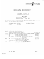
Manual Changes
Sales Office Locations
Specifications
Model 6960 A
TABLE 1-1
SPECI FICATlONS
REGULATED OUTPUT:
2 ranges switched by push button switch
0-18 V/600 mA: Voltage cantinuously adjustable
from 0-18 V dc.
600 mA over entire valtage range.
0-36V/3OO mAl
Voltage continuously adjustable
from 0-36 V dc.
300 mA over entire voltage range.
LOAD REGULATION:
Less than 5 mV change in output voltage over full
aperat ing range.
LINE REGULATION:
Less than 5 mV change in output voltage for
± 10% power line changes.
RIPPLE AND NOISE:
Less than 150 ;U Vrms •
TEMPERATURE STABILITY:
Less than O. 1 %;0 C.
TEMPERATURE RANGE:
Ot0550 C.
OUTPUT IMPEDANCE:
Less than 0.02 Q from DC to 1 Kc.
Less than 0.5 Q from 1 Kc to 50 kc.
RECOVERY TIME:
Less than 50 fJs after a change
from full 10aCl to no load.
METER ACCURACY:
~ 5% of full scole.(METERS ON OPTION 01 ONLY)
OVERLOAD PROTECTION:
Output current Iimiter continuously variable
from 80 to 600 mA on 0-18 V range,
40 to 300 mA on 0-36 V range.
OUTPUT TERMINALS:
Three banana jacks spaced 3/4 inch apart.
Positive and negative terminals are isolated from
chassis. A maximum of 400 V may be connected
between ground and either output terminal.
REMOTE PROGRAMMI NG:
About 200 Q/V external resistance applied to
rear-mounted terminals.
POWER:
110/220 V :: 10%, 50 to 60 cps, 40 watts.
115/230 V ± 10%, 50 to 60 cps, 40 watts.
6-3/32 inches (155 mm) high, 5-1/8 inches
(130 mm) wide, 11 inches (279 mm) deep.
DIMENSIONS:
WEIGHT:
1-0
Shipping 10 Ibs (4.6 kg)
Section I
Model 6960 A
SECTION I
GENERAL INFORMATION
1-1
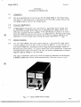
Introduction
1-2
This is on operoting and service manual far the Madel 6960 A DC Power Supply.
This manual is applicable only to instruments with the prefix number shown on the
title page except as modified by change sheets.
1-3
Instrument Identification
1-4
Hewlett-Packard instruments use a two-section, eight-cligit serial number, that
is, 000-00000. The first three digits are an identification number; the last five
digits are the instrument serial number. If the identification number on the instrument daes not agree with the identification number shown on the manual title page,
there are differences between the manual and instrument. These differences are
described in manuol chonge sheets having the prooer identificotion number.
1-5
General Decription
1-6
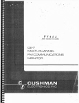
The -hp- Model 6960A DC power supply produces a regulated DC voltage continuously adjustable from 0 to 36 V up to a current of 300 rnA, or from 0 to 18 V up
to a current of 600 rnA, according to which range has been selected by means of
the front panel push buttons. The supply makes load circuit performance idepencient
of external power supply influences, has very low source impedance and excellent
regulation against change in line and load.
This supply is especially useful as a source of power for transistor circuits because
it features a protective circuit which electronically li;"its the maximvm OUTput
Fig. 1-1 Model 6960A Power Supply
1-1
~i:;;;mmmmmmm:::::::;;;:mmmmmmmm;mmmm;mmm;;m;;m;;
mmmmm;;;, ::i::,Fmm;;mmmm;""""""",,, :;""",,,,,''': ""'H':::;:.;;'.::;::;:"m:;;';;';';;';;::"':;;';;;1:::::::::::::""="'"''''''"'''' "","'""",=:::,::":::::"',,,,,,::,,,,,, ,,,,,,,,,,,,,,,,,,,,,,,,,,,,,,,,,,,,,,,,,,,,,,,,,,,,,,,,,,,,,,,,,l!I1Iil
IvIode I 6960 A
Section 1
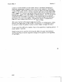
current to volues selected by 0 front ponel control. Accidental damaging of
expensive components by excessive current can thus be reduced to a minimum,
if the CURRENT LIMIT control is set to a value just above the normal operating
current of the external circuit. Another important appl ication of the Model 6960A
Power Supply is in electronic test systems where various fixed voltages have to be
produced sequentially with a high degree of reproducabil ity. This can be achieved
because the output voltage of th is supply may be programmed by an externally
connected fixed resistor or a series of same. The output voltage will then be proportional to the value of this resistor; changing the resistor in predetermined
steps will have corresponding effects on the output voltoge.
Both output terminals of the power supply are insulated from chassis ground. Either
terminal may be grounded as high as 400 V from ground. It is therefore possible
to connect a number of supplies in series to obtain higher voltages than 36 V.
If more current than 600 mA is needed, there is the possibi Iity of operating several
power suppl ies in parallel.
Remote sensing can be used for minimizing the effect of supply lead resistiance
and thus providing an exactly regulated voltage at the supplied circuit regardless
of lead length.
2-0
.................••.•..
_---
Section II
Model 6960A
SECTION II
INSTALLATION
2-1
Inspection
2-2
When the Model 6960A is received, inspect it for damage received in transit.
Operate the instrument to make certain that it is functioning satisfactorily. If
damage is evident, follow the procedures outlined in the "CLAIM FOR DAMAGE
IN SHI PMENT" page of this manual (inside rear cover).
2-3
Power cable
2-4
The three conductor power cable supplied with the instrument is terminated in a
three connector male power plug recommended by the VDE (Verein Deutscher
Elektrotechniker) •
WARNING
The third conductor grounds the instrument cabinet for the
PROTECTION OF OPERATING PERSONNEL. If 0 two connector line power receptacle is used, the instrument cabinet
should be grounded externally.
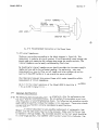
2-5
115 V or 230 , V Operation
2-6
The instrument is designed to work from 110, 115 or 220, 230 volts ± 10 % line voltage,
It is shipped from the factory wired for operation from a 110 V or 220 V source, It may be
re-wired for operation from a 115 V or 230 V line by changing connection on transformer
T1 from 4 A to 4 and from 2 A to 2 (see Figure 5-4), To operate from 220 V (230 V) line,
set the slide switch on the rear panel to 230 V, to operate from 110 V (115 V), set the
slide switch to 115 V, Fuse F1 should be 0.4 A slow blow for 220 V (230 V) and 0,8 slow
blow for 110 V (115 V),
2-1
Section III
Model 6960 A
SECTION III
OPERATING INSTRUCTIONS
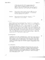
3-1
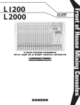
Operating Controls
Figure 3-1 shows the functions of the front panel controls and terminals and is
self-explanatory.
3-2
To turn the instrument on, push in either of the range buttons, according to the voltage
and current which is desired. Accidental setting of both buttons, 18 V and 36 V, will
cause no damage to the unit; in this case the instrument has been switched to the
36 V - 300 mA range. Pushing in the button marked OFF turns the instrument off.
3-3
Current Limit Control
3-4
This knob adjusts the peak current output of the supply. The indication is nominal. To
set the value exactly, remove the load and short the power supply terminals. Adjust the .!i.. .m
CURRENT LIMIT control until the meter indicates the required maximum current.
#,
If the supply is to be used in an application where the current drown from the
instrument is not essentially unifotm with respect to time, e.g. in pulse type
circuits, then the fast acting character of the current limiting circuit must be
taken into consideration. The average current may be within the supply rating
or below the maximum current set with the CURRENT LIMIT control, but peak
currents moy be high enough to cause the supply to clip. The CURRENT LIMIT
control must, consequently, be set to a value which is greater than the peak
current requirements of the circuit.
The output terminals are connected internally to a 200 juF capacitor which
helps supply high current peaks, provided they are of short duration. Any external capacity added will improve the peak current capability, but will decrease
the safety provided by the current Iimit control. High range currents may then
destroy external components before the average current inside the supply
increases sufficiently to cause the limiting circuit to operate.
3-1
;11'
Section III
tv\ode I 6960A
7
METER INDICATES OUTPUT
VOLTAGE
/
/
v
,0
,
/
,~
mA
'"
\' .' I""
I
Zo"l
"4c
,\1,1 ,,,I,, '/ "
I! -_.: ..~ 0»:~"
')11-'\ G
I
,'
VOLTAGE ADJUST
I"
WJe
'.
o
~a>?')
~_'-J,
110
:600
.0
RANGE
I
CURRENT LIMIT(mA)
'fo°
)~
o
METER INDICATES OUTPUT
CURRENT
/
r
I
100
~Selects
maximum
current output
CONNECT
LOAD
TO (+ ) AND (-)
+ r--_---,,-,-Hr---- TERMINALS
~@
'@"Eltherterminalmay
oe connected to
CJl'ounded cClblnet
terminal.
~ ~j
~
\
L
SETS
MAXIMUM
OUTPUT
VOLTAGE
PrM£~POWER
OFF
CABINET GROUND
ON
Fig. 3-1 Operating Controls
3-2
Section III
Model 6960 A
3-5
Connections to Load
3-6
The load may be connected to either the front or rear output terminals of the
power supply as shipped from the factory. Sensing of the output voltage is automatically accomplished in both modes of operation.
The user should realize that the specifications describing the electrical characteristics
of the power supply are given for measurements made directly at the
terminals. Long leads between instrument and load deteriorate load regulation,
which can only be maintained within the specifications of the power supply by
using remote sensing as described later in this section of the manual.
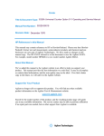
3-7
Automatic Parallel Operation
3-8
Automatic parallel operation as used here is defined as a parallel operation of
two or more power supplies with one unit (the master) acting as a control unit
and the additional units (the slaves) acting as controlled units, where each supply
automatically provides an equal share of current. Each Model 6960A can be used
as master or slave un it.
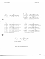
The connections of the supplies have to be made in accordance with Fig. 3-2 C.
NOTE
All un its must operate on the same voltage
range (0- 18V or 0-36V) !
Turn on the master unit first, then the slave units. Each supply will share the load
current and the master unit will automatically limit the voltage and the current
for all units.
Each slave unit sti II maintains its own short circuit protection and should be set
to a current limit slightly greater than the maximum current set on the master
unit. If the slave unit was set to a current limit slightly greater than the master
un it and if the slave un it was turned on first, the equipment under test might
be damaged by excessive current before the master unit was turned on and took
over the current control.
3-9
Automatic Series Operation
3-10
Two or more supplies may be operated in series to obtain a higher voltage than
that obtainable from a single supply. One unit (the master) acts as a control
unit, which controls the additional units (the slaves). The master will set the
total output voltage with each unit contributing the same amount of voltage.
Any Model 6960A may be used as master or slave unit.
Connect the output terminals of the units so that the two terminals of the
master are the most negative of all. The arrangements of interunit connections
are shown in Fig. 3-2 b for two units and in Fig. 3-2 d for three or more units.
The connection beween -S of the master and A 2, A 3 of the first slave has
to be done by means of a 10 K 0/0.5 W resistor.
3-3
~i:;'
Model 6960 A
Section III
Prior to turn on set the VOLTAGE ADJUST control on the master unit fully
counterclockwise and the ones on all slave units fully clockwise. Then turn on
all units and adjust the master unit to the desired voltage. If the slave units do
not track the master unit, turn off all instruments and recheck your connections.
For minimum ripple across connected outputs, add a 5 /uF (or larger) /50 V
electrolytic capacitor from +S to A2 terminals on all slave units. All instruments must be operated on the same range. Dl not connect more than ten
units in series to avoid exceeding the 400V rating from +or - output terminals
to chass is.
3-] 1
Remote Programming
3-12
The output voltage of Model 6960A may be changed by actuating the front
panel VOLTAGE ADJUST con,rol or by chong"'::; ,ll"C '''''0'' or the externa'i
programming resistor. If a number of Model 6960A's are connected in series
or parallel, all units can be conrrolled by cho'lgi"9 rt;e programming resistor
attached to the master unit only. Thus the output voltage may be programmed remotely by using stepping switches to change the value of the external
resistor in accordance with a programmed procedure.
The connections on the rear terminal strip, shown in Fig. 3-2 e have only to
be performed on the master unit. Then the output voltage will vary lire~·I,:
with the programming resistor at a rate of approximately 200 O/V, that means,
a 2000 resistor wi II give 1 V output, 0400 0 resistor 2V output, etc.
When using a switch to change the programming resistance whi Ie the instrument is on, be sure to use a shorting contact type switch to keep the voltage
of the supply from rising while switching. If the programming circuit is opened,
even momentarily, the voltage from the supply will rise. This switching transient may damage the circuit under test.
3-13
Remote Sensing
When the rear terminals of the instrument are connected in the normal fashion,
the voltage for regulation control (sensing voltage) is taken from the output of
the supply at the front panel. This is not always the best point to obtain this
voltage, because there may be a voltage drop in the supply leads between the
load and the supply.
To get around this effect, a separate set of terminals for the sensing voltage
(+S and -S) are provided on the rear of the instrument. These terminals permit
a separate pair of leads to connect at the load to supply the sensing voltage.
The leads carry no load current but are inside the regulation loop of the
ampl ifier.
To use remote sensing, run a separate set of leads from the load to the sensing
terminals. These leads do not need to be as heavy as the supply leads but they
must be protected against hum pickup. Run either twisted pair open wire leads
3-4
._-""--
-----------~.~_."""",.,''''''''''''''''''''''''''''''','''''".""
, " " " "" ""."" ,••",, , , , , , , , ",, , , , , , , , , , , , ,., , , ..,,., , . , , , , , , , , , ·.•.•."••••m.'
Model
Section III
6960 A
or shielded leads if hum pickup is severe. Connect the leads to the sensing terminals + 5
and -5 on the rear of the instrument. At the load. attach these leads across the load.
Remove the shorting link between (-) and (-5) and (+) and (+5).
CAUTION
Do not operate the instrument with the sensing
leads open. Be sure to observe polarity when
making these connections. Wrong connections
may damage the supply.
If the instrument is operated in this manner, the maximum output current decreases at a
rate of approximately 8% per every 100 MQ of resistance in the minus load lead.
3-5
··················"""",,,,,,,,,,,""'''';;m;>;;;;'',,;:;:±:i1!';il
Section III
Model 6960 A
FRONT
0
o
ferh
REAR
FRONT
,
0
.0.5
0
0
0
-
-S
AI
+5
AZ 43
ULU
o
U
+
.0.4
o
LFJJ
0
(a) Normal Operation
( b)
REAR
F"RONT
C!~\J
CIJ
(e)
I
o
A5
0
-
-5 AI
42 A3
+5
+
~r-~- - - u
A4
0
0
I
MASTER
0
~t ~
o
45
0
Auto - Series Op.ration
U
for
FRONT
~
--'
A243
0
+(j
A4
o
0
SLAVE
2 Unit.
REAR
lGh
- - 5 A. A 2 A 3
+ 5 + A4
0090
000090
A5
I
C2J
REAR
'::'5
I
o
-
° °
-5 A
A2t.3
+5
+
A4
91.-_0_ _)_0_0_0_0---,9
Auto- Parallel Operation for
°
SLAVE
I SLAVE
u~
~
(d)
:3 Units
0
(e)
+o
for
3 Unite
REAR
FRONT
i
Auto - Series Operation
0
-
0
Remote Programming
Figure 3-2 Terminal Connections
3-6
Section IV
Model 6960 A
SECTION IV
PRINCIPLES OF OPERATION
4-1
Overall Block Diagram
4-2
As shown in Figure 4-1 the power transformer feeds two fullwave rectifiers. The
rectified AC is filtered and controlled by a series regulator. The two built in
series regulators can be operated either in series or parallel depending upon the
selected range of the push button switch and are controlled from the error
ampl ifier man itoring the output vol tage of the supply.
The voltage monitoring error amplifier senses any change in the output voltage
compared to a reference voltage. The output of the amplifier causes the resistance of
the series regulator to be varied in such a way as to keep the output voltage constant.
The programming current, determined by the reference voltage and the series resistor
R 35, flows mainly through the VOLTAGE ADJUST potentiometer R 40. The product of
the programming current and the value of R 40 equals the output voltage.
4-3
Circuit Description
4-4
The schematic diagram (Fig 5-4) shows all details of the circuit. Power transformer is shown to consist of three secondary windings of which the upper two
are the main sources of DC power, while the lower supplies the reference and
auxiliary voltage circuit. Rectifier bridges CR 3 to CR 6 and CR 7 to CR 10
are coupled by R 1. Fi Itering is provided by capacitors C2 and C3. Resistors
SUPPLY
RECTIFIERS
SUPPLY
REGULATORS
ERROR
AMPLIFIER
POWER
POWER
>-to TRANSFORMER
LINE
REFERENCE
RECTIFIERS
REFERENCE
REGULATORS
Fig. 4 - 1 Block Diogram
4-1
OUTPU T
Section IV
Model 6960 A
,,
R 3 and R 4 allow a current flow through the rectifier bridges even when no output
current is drawn from the instrument. Series regulators Q 1 and Q 2 act as variable
resistors determining output voltage and current. The output current from one regulator
is monitored by the resistor combinations R 39 B, R 9 and R 8, while R 39 A, R 9 and R 10
monitor the current from the other regulator. The voltage drop across these resistors is
applied to the emitter of Q 5. When this potential exceeds a dist inet value determined
by R 39 A and B and the load current, transistor Q 5 is caused to clip. From then on
Q 5 holds the base voltage and hence the emitter voltage of Q 1 through CR 13 and
voltage amplifier Q 3, thus preventing any further increase in the load current. Voltage
divider R 5, R 6 adjust the base-emitter voltage of transistor Q 2 if the power supply is
driven in the 36 V / 300 mA range. The ammeter (M 1) indicates the output current by
measuring the voltage across R 22 and the voltmeter M 2 indicates directly the output
voltage of the power supply.
The voltage error amplifier consists of the two transistors Q 7 and Q 8 besides Q 3. In
the constant voltage mode changes in the output voltage due to changes in load or line
voltage are amplified and applied to the base of Q 1 in such a way as to keep the output
voltage constant. R 23 is used to adjust the positive feedback from the collector of Q 8
to the base of Q 7. A proper adjustment of this feedback will result in no output voltage
change when the load current is changed from no load to full load. It can even be
adjusted to yield a negative output resistance, i. e., when a load is applied, the output
voltage increases rather than decreases. Normally, this is adjusted to give zero output
resistance and not a negative resistance.
CR 14 and CR 13 are disconnecting diodes. In the constant voltage mode CR 13 is
closed, CR 14 open, so that the current error amplifier is out of circuit. In the constant
current operation CR 13 will be automatically opened and CR 14 will be closed to isolate
the voltage error amplifier.
The reference supply consists of a complete feedback amplifier, Q 4 and Q 6. The
reference voltage itself is controlled by zener diodes CR 20 and CR 21, which also
stabilizes the negative auxiliary voltages. R 41 helps to supply the thermal stability of the
base potential of transistor Q 5. Manufacturing tolerances of CR 21 are compensated by
factory adjustment of R 27 by means of shunt resistor R 38. The value of R 17 allows
current changes proportional to line voltage changes. These current changes compensate
possible variations of the current through CR 21 with line voltage variation and minimize
changes in output voltage.
4-2
"'''ii'''''''''''''''=,",
_
.
Madel 6960 A
Section V
SECTION V
MAl NTENANCE
5-1
Introduction
5-2
This section contoins mointenonce and service information for the Model 6960 A
Power Supply. A performance check can be made with the instrument in its cabinet
and is a good test as port of prevention maintenance and incoming quality control
inspection.
5-3
General Maintenance Information
5-4
The power supply has no parts which have a definite limited life. The instrument
should operate indefinitely with no routine maintenance. If any parts are replaced
you should recheck the settings of R 7, R 10 {maximum short circuit current}, R 23
{load regulation} and, if necessary, R 20 and R 21 {meter adjusts}. Variations
among ports may make it necessary to readjust the controls slightly. Reseal the
controls with adhesive or point after adjustment, otherwise the setting will change
with shock and vibration.
...
A list of possible troubles and the probable cause are tabulated in poragraph 5-12.
In each case curing the trouble involves replacing the defective parts. Be careful
when soldering on the etched circuit board.You can couse damage by excessive
heat or improper technique.
5-5
Test Equipment Required
5-6
Test equipment required to test this instrument is listed in table 5-1. The necessary
specifications required to obtain reliable test results are listed so that other equipment with equivalent specifications may be used.
l
!
I
I
I
I
5-1
~~~~~_.
_....__••....•................................•.............
Model 6960 A
Section V
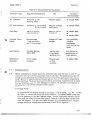
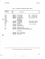
Tobie 5-1 Recommended Test Equipment
Instrument Type
Required Characteristics
AC Voltmeter
Use
Instrument
Recommended
Accuracy ± 3 %
Floating input
Measure ripple
I!jJ Model403B
DC Volt-Ammeter
Accuracy ± I % Voltage
± 2 % Current
Measure voltage
and current
I!jJ Model 412A
Oscillator
100 Hz to 100 kHz
Distortion 0.5 %
Measure internal
impedance
I!jJ Model200C
or
I!jJ Model202C
'8
Variable Transformer
Mon itormeter
1 volt resolution
and 1 % accuracy
Change AC input
voltage
Lood Resistor
Vorioble Resistor
150050W
Load for measuring ripple,
regulation etc.
Differential
Voltmeter
10 mV-range
necessary
Measure load
and line
regulatian
Any available
variable
transformer
with monitoring
meter
Any resistor or
combination of
fixed resistors
I!jJ Madel 740A
5-7
Performance Test
5-8
Before attempting to trouble shoot this instrument make sure the fault is with the
instrument and not with the associated circuit under test. The performance test wi II
enable you to determine this without having to remove this instrument from the cabinet. Be sure to perform this test before disturbing any ot the internal adjustments
of the instrument. This test moy also be used as an incoming inspection test to make
sure the instrument has not been damaged in shipment, for periodic maintenance or
to check operation of the instrument after repairs.
a) Voltage Range.
An external DC-Voltmeter having an accuracy of 1 % or better, i.g. the I!jJ Model 412A, is connected across the output terminals. The Model 6960A under test
is to be operated in the 36V-300 mA range. Turn the VOLTAGE ADJUST clockwise until the 412A indicates 36V output. The knob must have been turned more
than 180 degrees • Turn the VOLTAGE ADJUST fully counterclockwise. Output
voltage should ga through zero to between 2 and 100 mV negative.
5-2
"".,
" "
""""".""."""""""."".",,,
""'''''"",,,!I!Hi
Model 6960 A
Section V
b) Current Limiting.
Switch off Model 6960A under test and connect the Model 412A with the current range across the output terminals. Turn the CURRENT LIMIT fully clockwise. VOLTAGE ADJUST should be in a mid range position. Push the buttons
18 V-0.6 A or 36-0.3 A and wait 15 minutes. When the instrument has warmed
up measure the maximum short circuit current in both ranges. The 412A should
read about 340 rnA in the 36V range and 680 rnA in the 18 V range.
c) Ripple.
Attach the load resistor for 18 V and 0.6 A to the output terminals and adjust
the output voltage and current to these ratings. Connect the floating input of
AC-Voltmeter 4038 (or equivalent) ungrounded AC-voltmeter to the output terminals. The readout of the 4038 should not exceed 150 ;UV. In the 36 V-0.3 A
range the same result should appear.
d) Load regulation.
For the connections, refer to block diagram in Figure 5-1. If the load is switched off ond on the output voltage change in both ranges should not exceed 5 mV.
Th\" "internal resistance" of the power supply under test should be positive, that
is, with load off the output voltage should be higher than with load on.
If you lock a good differential voltmeter, take a second Model 6960A or another
constant voltage source and compare the output voltage changes to the power
supply under test using a sensitive DC-voltmeter like the 1j Model 412A or
ilj Model 425 A.
e) Line regulation.
Take the same connections as in paragraph 5-8d, change the line voltage of the
Model 6960A under test by means of a variable Iine transformer between 198 V
and 242 V. The change in output voltage should not exceed 5 mV on both
ranges.
5-3
Section V
Model 6960A
DIFFERENTIAL
VOLTMETER
VARIABLE
TRANSFORMER
ADJUSTABLE
FROM 19B - 242V
0--
6960 A
220V'"
I A - : - C : : - - - - I - - - - - - - + - - + - - - - - - - - - - - r o = - C : : - - - i CONTROLS
OUTPUT
VOLTMETER
VOLTMETER VOLTAGE
MEASURES
RIPPLE
LOAD SWITCH
Fig. 5-1 Measuring Line, Load Regulation and Ripple
AC
VOLTMETER
220V'"
MEASURES INTERNAL
IMPEDANCE
10V ~ 1000.ll.
6960A
OSCILLATOR
IK
1/50
AC
VOLTMETER
MONITORS CLRRENT
10V· lOrnA THROUGH I KA
Fig. 5-2 Measuring AC Internal Impedance
5-4
Model 6960 A
Section V
OUTPUT TERMINAL
DO NOT
MONITOR HERE
LOAD
A
LEAD~
'-------1
MONITOR HERE
~
Fig. 5-3 Recommended Connection at the Power Supply
f) AC Internal Impedance.
Make your connections according to the block diagram in Figure 5-2. This
measurement is made by driving a constant 10 mA alternating current through the
power supply and measuring the voltage drop across the output terminols. The
internal impedance can be easily calculated by Ohm's law.
By checking the internal impedance you should consider that the power supply's
ripple and noise add to the voltmeter reoding. For performing very exact
measurements you have to fi Iter out all ripple and noise voltages up to a frequency of about 500 cycles or to use a sensitive wave analyser.
Also take care to prevent stray ground loops which make impossible reliable
measurement of internal impedance.
Up to 1 Kc the internal resistance of the Model 6960 A should be below 0.02 Q
1 Kc up to 50 Kc below 0.5 {1 •
5-9
Detailed Test Procedure
5-10 The following test procedure should be performed only after the performance test
has shawn that this instrument is faulty. Do not perform this procedure as an incoming inspection or proof of performance check. The following test procedure contains
extra checks to help you analyze the troubles in this instrument. These extra checks
and the data they contain cannot be considered as specifications.
Because of internal adjustment or even possible replacement of components, top,
bottom, and the side covers may have to be removed. Make sure that the ac fuse
is inserted in the fuse holder. The VOLTAGE ADjUST an the front panel should be
in a mid-range position, the CURRENT LIMIT control turned fully clockwise. Use
5-5
Model 6960 A
Section V
an ohmmeter, e.g. iFiJ Model 412A, to make certoin the negative output terminal,
the pasitive output terminal, and the collectors of Q 1 and Q 2 are nat grounded.
Now switch the Model 6960A on. Vary the output voltage in both voltage ranges
with the VOLTAGE ADJUST to be sure that the voltage control is operative.
a) Meter Zero Set.
When the instrument is at normal operating temperature and then switched off,
the meter pointers must rest on the zero calibration mark af the meter scale. If
they are outside the zero mark, adjust the them as follaws:
After turning off the instrument wait two minutes for power
supply capacitors to discharge completely. Rotate adjustment
screw below the meter scale clockwise until the meter pointer
is to the left of zero and farther clockwise rotation will move
the pointer upscale towards zero.
Turn the adjustment screw clockwise until the pointer is exactly
over the zero mark on the scale. If the screw is turned too far
repeat the procedure.
Turn meter adjustment screw sl ightly counterclockwise ta break
contact between adjustment screw and pointer mounting yake,
but not far enough to move the pointer downscale. If screw
is turned tao far, as shown by needle movement, repeat the
procedure.
b) Volt Meter and Ammeter Calibration.
Set the output to exactly 36 V controlled by an external dc valtmeter which
has better than 1 % full scale errar, i.g. iFiJ Model 412A. Adjust the builtin valtmeter to exactly 36 V by means of variable resistor R 20. Switch the
Model 6960A under test into the 18 V-0.6 A range and bring the output
current to exactly 600 mA, controlled by an external dc ammeter like the
~~ Model 412A. Adjust variable resistor R 21 so the front panel ammeter
reads exactly 600 mA.
c) Maximum Short Circuit Current.
The short circuit current can be measured either by measuring the voltage
drop acrass a 1() precision resistor between the autput terminals or by
switching aff the instrument and connecting the current leads of the
madel 412A across the autput terminals and turning an the Model 6960A. The
CURRENT LIMIT canrrol must be set fully clackwise.
The maxium rating of shart circuit current shauld be 360 mA ar 720 mA
respectively; the minimum ratings are 330 mA or 660 mAo The naminal and
factary adjusted values are 340 mA and 680 mAo These ratings should be
adjusted as follaws, if the shart circuit current turns aut ta be too high ar
taa law.
5-6
,';.,'-,- ;.,';;; ;;;.;.: •••; •• ;;;•• ;.;.;.;;;;;;; •• ;;.;;:.;;;;;;;;;:;;;;;;:;;;;;;;;;;;;;;;;;;;;;;;;;;;;;;;;;;;;;;;;;;;;;;;;;;;;;;;;:;;;;;;;;;:;;;:;;;:::;::;;:;:::::::::::::;;;Hi
Section V
Model 6960 A
At first select the 36 V-0.3 A range and adjust short
circuit current by changing the position of R 7 to
340 mAo Then switch the power supply into the 18V-0.6 A
range and adiust short circuit current with R 10 to 680 mA.
Caution:
Do not allow current ratings of more than 400 mA to flow
through either of the series regulators. This may destroy
the series regulators Q 1 and Q 2 !
Attention:
Before performing this odiust, the instrument has to be
warmed up to its normal operotir\8 tenlpeia~ure.
d) Ripple.
Measure ripple according to paragraph 5-8 C. Change th" line voltage of the
power supply between 198 V and 242 V. Within the whale runge the ripple voltage should not exceed 150 /u Veff. If 'here is a grad ..,.:,; ;:~'J;' i",ple over
I
150 /,Vrms while decreasing the line voltage towards 198 V, transistor Q 6
has stopped working. Remove R 33 and replace it with a aecade resistance. Vary
the input line voltage between 198 V and 242 V and adiust the decade so that in
the whole range the ripple voltage remains below 150 /,Vrms. At the some time
check the voltage between minus lead of capacitor Cl and -S. It <.hould read
-14V :: 2 %, otherwise transistor Q 4 will not regulate properly. Replace the
decade value with a fixed resistor of equal value.
e) Load Regulation.
For measuring circuit refer to paragraph 5-8 d. If the output voltage change is
greater than 5 mV while switching the load off and on, adjust resistor R 23 so
that the change is within the specification. After setting R 23 turn the VOLTAGE ADJUST knob fully counterclockwise. A de voltmeter across the output
terminals of the power supply must indicate a negative voltage between -2 mV
and -100 mY.
f) Line Regulation.
If the adjustment described in paragraph 5-10 d has been done carefully the
output voltage change caused by input line voltage changes should normally
be within the specification. If there are, nevertheless, excessive changes,
remove R 37 and replace it with a decade resistance. The decade is adjusted so
the change of output voltage lies within specification. Replace the decade
with a fixed resistor of equal value.
5-7
Model 6960 A
Section V
5-11 Troubleshooting
5-12 Components within Hewlett-Packard instruments are conservatively aperated to
pravide maximum instrument reliability. In spite of this, parts within an instrument
may fail. In this case a systematic approach can greatly simplify and thereby speed
up the repair.
CAUTION
Be careful nat to short voltages across the transistors, small bias
changes may ruin a transistor due to excessive dissipation. Be
sure to turn the instrument off before doing any soldering.
If there is no voltage throughout the instrument check the fuse and primary transformer circuit. Transistors Oland 0 2 should have a voltage drap af about 5 to
6 V across them. If the pilot lamp is an but the de output shows no '!olhge or
excessive voltoge with high ripple check all voltages produced by the auxiliary
and reference voltage supply. These voltages should be at ratings sho.,,' in the
schematic diagram and should not exhibit significant changes while varying the
input line voltage. If all of these voltages are operating properlY ,i'e Trouble lies.
in the amplifier loop. Check each transistor of the amplifier, ;ncl·.~;cg fhe diodes
CR 13 and CR 14 as well as the front panel potentiometer R 40 (VOLTAGE ADJUST).
Some symptoms indicate, with high degree af probability that certain components
may be faulty. Refer to the trouble localization chart belaw.
Table 5-2 Trouble Localisation chart
Symptom
Blown Line fuse
Check
Primary circuit of T 1
T 1 itself, CR 1 to CR 10
CltoC3.
Either 18 V or 36 V range
on Iy is work ing proper Iy
Push button sw itch
Excessive short circuit current
R 7, R 10, R 39 AB, 0 5
Poor current limiting.
Poor stability of output voltage
CR 20, CR 21, R 40
Poar load regulation
08,07, CR 14,03
Poor line regulation
CR21, 06, 04
After replacing faulty components carry out the performance test according to paragraph 5-7 and, if necessary, the adjustment procedure according to paragraph 5-9.
5-8
_ _ S2
Jv\ode I 6960A
(SHOWN_'~36V ~SITI~)_ _
WHT-BRN-GY
_
_
_
21VAC
I
AMMETER
0.3AI
~0 ADJUST
-------+.--W>v-----------,
I
I
r'~./
WHTBRN - L - GY
J36V
+ C3
;::~
1000
I
""
+17.3V
I
""
+12.4
R39A
10
R6
360
-14V
GY
"'-'---<1
r
~
1
WHT-GRN-GY 3
8
WHT-
2
A
CR5
(
I
I
I
~
CR4
1000
R3
• 1000
OSI
~
R36
33K
"WHT-YEL-GY
I
GY
NOTES
I.
2.
3.
4.
5.
, 360
-6.5~~
.~
~
-0.4V
n
- 0.7 V_ _-+-
,I
05
R7
10
0082
I
+
VOLTAGE
AMPLIFIER
b
l -_ _---4\l---=0~.7..:.V_+_6_.8_V
_ _~(n\
1000
I
I
~
I
I
..
+1.5 V
RI5
390
.,.....
I
I
WHT-RED-GY rr
J
10
I
I ~III
.
+
CI
WHT- BLK
20 VAC
• R37
~ RI7
• (SHUNT) > 15 K
~2
: RI2
RF.GULATOR
....11.0 V
r:-~'
e0
03
-6.8V
~~~K
+ 0.5V
~~CR20
Z
5-9
R34
430
-J,...
R 14
-j<t-9't---,
IOOO...,.,.,_ _
~~CR21
COMPARISON ~
AMPLIFIER
R30
.~33
+
:::"C7
20
_~ few I
~~
0---
10K
CRI8
~r
CRI9~ ~
R31
-0.03V
-6.8V
J
A3
-0.15V
1300
AI
."
DIFFERENTIAL
AMPLIFIER
---.-
J
0
BLK
+ 1.5 V
• R41
• 270
-+-
..- _0.03V
.....
.- -0.35V
R29
300
L--
-&6V
f
Ir
R35
R32
~15_0
, ~CRI6
A4
C5
100
LJ----I-----4~--"---"'N~---oCll:;A2
...
R25
·2700
Figure 5-4. Model 6960A Circuit Diagram
L--~--------.+_----_t_------------.- - 6.8 V
L
AS
WHT-BLU
JI,J2
MI,M2
PI,P2
01-08
RI-R42
SI,S2
TI
WI
WHT- BLK- VIO
• R42
~ 10K
+6.8V
~~~
~. CRI7
04
06
El
J
+ 1.10 V
j
-0.02V
LOAD
REGULATION
ADJUST - 0.03 V
WHT-RED-G~
CI -C9
CRI-CRI4,CRI6-CR22
DSI
FI
~
...
VOlTAGE
[ ADJUST
07.08
~ SERIES
• 300
~
...
I
10K
\.-......---...----~~---------- ...
- ... 6.8V
;;:~500
20VAC
R33
33K
I
+11.2V
~
WHT-VIO
, R24
~
RII
----
GJ
-S
- . . . . . .
R26
6.8K
~ ~CR22
;;: ~C4
20
1.8
+ l5V
*C9:::~
j
150
.~RI8
: 33K
C610
-I4V
;:::
~
REO
'1+
I
C8
...
RI3
220
I
~
~
__ J
...
R'B
___I
I
I
I
CURRENT
AMPLIFIER"
-0.35V
o
\
R398
10
~-
R20, ~cw
;
10K
I
VOLT - METER
CURRENT
ADJUST
LIMIT
ADJUST
I
~] ,WHT-VIO
1\;"
P'I
SERIES
REGULATOR
01
RESISTANCE IN OHMS,
CAPACITANCE IN MICROFARADS ••.1
VOLTAGES MEASURED WITH
RESPECT TO -S AT 36V -O.3A.1
*AVERAGE VALUE SHOWN.
FACTURY SELECTED.
0 EXTERNAL CONTROLS,
~ INTERNAL ADJUSTMENTS.
TRANSFORMER CONNECTIONS
FOR 1I0/220V OPERATION.
USE TERMINALS 2 AND 4
FOR 1/5/230 V OPERATION.
REFERENCE
DESIGNATIONS
~
R5
BLU
I
LJ 0- - -..,
I
ORNGY
..0---'---0--,
1
~II
1.0
I
I
~--+-....._-.......- - - - -.....C..R~.lt-'12'"'t
+;;:~2
RIO
I
ICURRENT
I
~ILlMIT (mA)
I
R2
3900
CR6
.
/
T
WHT-ORN-GY
~ 21 VAC
+
I
RI
, 3300
(
J2
R9
1.8
~"'WHT
I
02
WHT-BLK-GY
MI
-f1t1,4WHT -BLK-RED
1
ORN
I
i
SERIES
REGULATOR +17V
7
A
0--
I
\
-+----.j~-_4_-,
HT - RED
R22
I S2C
IoR4
: 1000
Section V
cS
R21
250
RI9
390
I
IC~~8
6
_
S2B
/iCRO
5
i
-.=r
1,8V 0.6AI
R27
R38
(SHUNT).....-_
i
_-4. 1000
.... -14V
Model 6960A
Section V
SERVICING ETCHED CIRCUIT IOARDS
Excessive heat or pressure can lift the copper strip from the board. Avoid damage by using a low power
soldering iron (50 watts maximum) and following these instructions. Copper that lifts off the board should
be cemented in place with a quick drying acetate base cement having good electrical insulating properties.
A break in the copper should be repaired by soldering a short length of tinned copper wire across the break.
Use only high quality rosin core solder when repairing etched circuit boards. NEVER USE PASTE FLUX.
After soldering. clean off any excess flux and coat the repaired area with a high quality electrical varnish
or lacquer.
When replacing components with multiple mounting pins such as tube sockets, electrolytic capacitors, and
potentiometers, it will be necessary to lift each pin slightly. working around the components several times
until it is free.
WARNING: If the specific instructions outlined in the steps below regarding etched circuit boards without
eyelets are not followed. extensive damage [Q the etched circuit board will result,
1. Apply heat sparingly to lead of component to be
replaced. If lead of component passes through
an eyelet in the circuit board. apply heat on com...
ponent side of board. If lead of component does
not pass through an eyelet, apply heat to Coilauctor side of board.
2. Reheat solder in vacant eyelet and quickly insert a small awl to clean inside of hole. If hole
does not have an eyelet, insert awl or a #57
drill from conductor side of board.
CONDUCTOR
SIDE
3. Bend clean tinned leads on new part and carefully insert through eyelets or holes in board.
4. Hold part against board (avoid overheating) and
solder leads. Apply heat to component leads on
correct side of board as explained in step I.
In the event that either the circuit board has been damaged or the conventional method is impractical, use
method shown below. This is especially applicable for circuit boards without eyelets.
). Clip lead as shown below.
~,-----r---CLIP
~HERE
2. Bend protruding leads upward. Bend lead of
new component around protruding lead. Apply
solder using a pair of long nose pliers as a
heat sink.
...,,~
SOLDER
#W9ill9Willill
~
This procedure is used in the field only as an alternate means of repair. It is not used within the factory.
5-10
Iv\ode I 6960A
Section VI
SECTION VI
REPLACEABLE PARTS
6-1. INTRODUCTION.
6-3. Miscellaneous parts are listed at the end of
6-2. ThIS sectlOn contains information for ordering
replacement parts. Table 6-1 lists parts in alphanumerical order of their reference designations and
indIcates the deSCrlptlUn and .'i stock number of each
part, together with any applicable notes. Table 6-2
llsts parts In alpha-numerical order of theIr $ stock
number and prOVIdes the folloWing informatIOn on
each part:
a DescrijJtion of the part (see Est of abbreviatlOns
below).
b. Typical manufacturer i)f the part In a fIve-dIgit
code. see list uf manufacturers In Table 6-3.
c Manufacturer's part number.
d TDLII quantity used
ill
the instrument (TQ column).
Table 6-1.
6-4. ORDERING INFORMATION.
6-5, To order a replacement part, address order or
inqUIry to your local Hewlett- Packard Field Office
(see maps at rear of this manual for addresses).
6-6. Speclfy the folloWing information for each part:
a. Model and complete serial number of instrument.
b. Hewlett-Packard stock number.
c, Circuit reference designatlOn.
d. Descnption.
6-7. To order a part not listed in Taqles 6-1 and
6-2, give a complete descnptlOn of the part and
include its function and location.
REFERE!"CE DESI(j;";ATORS
assemblv
mvlur
t:apa,'I!or
cuupllng
E
F
CR
dwue
K
DL
dplay linc
d!:'Vice Signaling (lamp)
L
A
B
r:p
OS
FL
J
M
mlSC ele;:tronlc part
fuse
filter
Jack
relay
inductor
meter
MP
P
Q
R
RT
S
T
m!?chamcal part
plu~
translstur
resistor
thermistor
SWitch
transformer
fB
Y
termwal board
test point
vacuum tube. neon
buIll, photccell, etc.
cable
socket
crystal
RMO
RMS
rack mount only
root-mean-square
TP
V
W
X
ABBRE\'IATIONS
A
A.F.C
A\lPL
amperes
aulumatic frequency control
ampllfler
GE
GL
GHD
germarllum
glass
ground(ed)
N/C
NE
NI PL
N'O
B. F. O.
BE CtJ
SH
BP
BRS
ewo
CCW
eER
(:.10
OEF
'_'0\1
CO:\lP
Iwat frequenq oscillator
bprvlllum copper
bllider h~'ad
bandpass
brass
backward W;:\I e ')5(' llal(,r
counter ,';".·kwise
('praml'
CP
cabInet flj',un~ ',nb'
('(J ",ll I [' , " ~ , j
cum:nun
eomp",.,it Il"l
(,00n(','j'.·r
CdOtrl,-.,rl! pIJt'·
(~RT
(at ~": ,';'
i:"'W
l' J,,' J('~,
( '0';'\
r a\ t;JlJi'
'>('
DEPC
dtj""-ll('d carbun
DR
,:lr,'.f'
ELECT
E;-;CAP
('l~,-trul'iti,
EXT
faraL1.~
FIL H
fllJ;~I('r
FXD
[I.'l'd
rial h<-ad
6-1
h~nrtes
HG
mef('urv
hr,ur(sJ
HR
IF
1:-1'
mtl"rmediate freq
impregnated
Inrandescent
lI'.(' lude(s)
Irlsillation(ed)
lrlterr,ai
K
kdr; , 1000
l\lPG
I!\'CD
f};CL
1'S
[wad
linear ta(Jt'f
US
LK WASH - !"Il:k waS)d.'r
LOG
lugar,tll."lll" tap"r
low pass fdt~'r
LPF
10 -3
milli
meg < 10. 6
MEG
METFLM = metal film
MFR
manufacturer
~lINAT
miniature
momentary
MO\I
MTG
mounting
mylar
MY
N
NPO
h('~a.g()nal
M
t'n"arsu1ated
<,xt"rna!
F
FH
H
HEX
nanu (10 'I
1"RFR
NSR
normally closed
neon
nickel plate
normally open
negattve posHi\'e zero
(zero temperature
coeffir:ient)
not recommended for
fIeld replacement
not separately
replaceable
OBD
OH
OX
urder by descriptIOn
o\'al head
oxide
P
PC
PF
peak
printed CIrcuit
picofarads '"
10- 12 farads
phosphor bronze
PhillIps
peak inverse voltage
part of
polystyrene
porcelam
positlon{s)
potentiometer
peak-to+peak
POInt
re,tirier
radio frequency
round head
PH BRZ '"
PHL
PIV
P '0
POLY
PORC
POS
POT
PP
PT
RECT
RF
RH
slow-blow
screw
selenium
section(sl
SECT
SEMICON '" semiconductor
silicon
SI
silver
Sll
slide
Sl
special
SPl
stainless steel
SST
split
ring
SR
steel
STl
S-B
SCR
SE
Tel
TJ
Tal
TRIM
TWT
tantalum
time delay
toggle
titanIum
tolerance
trimmer
traveling wave tube
U
micro'" 10- 6
VAR
variable
dc working volts
TA
TIl
VDCW",
Wi
W
WW
WiO
with
watts
wlrewound
without
Model 6960 A
Section VI
Table 6-1. REFERENCE DESIGNATION INDEX
Reference
Designation
'.
C 1
C 2 thru
C 3
C4
C 5
C 6
C 7
C 8
C 9
CR
CR
CR
CR
CR
CR
CR
CR
CR
CR
CR
CR
•
t:;·
1 thru
11
12
13 thru
14
15
16 thru
18
19
20
21
22
-hpStock
No.
Note
Description'
0180-0502
0180-0518
C: FXD, Elect.
C: FXD, Elect.
500"F
1000 flF
29 VDCW
31 VDCW
0180-0049
0150-0012
0180-0032
Elect.
CER.
Elect.
20 flF
0.D1 flF
10 flF
50 VDCW
1000 VDCW
10 VDCW
0180-0131
0150-0082
C: FXD,
C: FXD,
C: FXD,
see C 4
C: FXD,
C: FXD,
Elect.
CER.
1501,F
8200 flF
63 VDCW
500 VDCW
1901-0026
Diode - Silicon
1901-0025
1901-0033
Diode - Silicon
Diode - Silicon
Not assigned
see CR-12
1902-0048
1902-0057
see CR-l
Diode - Zener
Diode - Zener
see CR-1
OS 1
F 1
F 1
2140-0015
2110-0019
2110-0020
Lamp- Neon
220 V: Fuse cartridge 0.4 A, Slow blow
110 V: Fuse cartridge 0.8 A, Slow blow
J 1
J 2
J 2
1251-0148
1510-0503
1510-0009
Connector Power
Binding Post Red
Binding Post Black
M 1
M 2
1120-0513
1120-0512
Meter Ampere
Meter Volt
P 1 thru
P 2
see W 1
• see List of Abbreviations in introduction to this section
6~
Section VI
Model 6960 A
Table 6-1. REFERENCE DESIGNATION INDEX (CON'T)
Reference
Designation
-hpStock
No.
Description *
Note
o
1850-0168
Transistor-Germanium
o
1850-0169
1850-0509
1851 "0017
Transistor-Germanium
Transistor-Germanium
Transistor-Germanium
0690·3321
0690-3921
0693-1021
R: FxD, Compo
R: FxD, Compo
R: FxD, Compo
0692-3615
0692-3315
2100-0507
0813·0503
R: FxD, Compo
R: FxD, Compo
R:VAR,WW
R: FxD, WW
1 thru
02
03
04
5 thru
08
R
R
R
R
R
R
R
R
R
R
R
R
R
R
R
R
R
R
R
R
R
R
R
R
R
R
R
R
R
R
1
2
3 thru
4
5
6
7
8 thru
9
10
11
12
13
14
15
16
17
18
19
20
21
22
23
24
25
26
27
28
29
30
0686-1025
0686·3015
0687-2211
0687·1021
0686·3915
0687-3921
0687-1531
0687-3331
0687-3911
2100·0505
2100-0503
0813-0502
2100-0504
0686-3335
0687·2721
0687-6821
0686-7515
0686-3305
see R 7
R: FxD, Compo
R: FxD, Compo
R: FxD, Compo
R: FxD, Compo
R: FxD, Compo
R: FxD, Compo
R: FxD, Compo
R: FxD, Compo
R: FxD, Compo
R: VAR,Comp.
R: VAR,Comp.
R:FxD,WW
R: VAR,Comp.
R: FxD, Compo
R: FxD, Compo
R: FxD, Compo
see R 11
R: FxD, Compo
see R 12
R: FxD, Compo
NPN 2 N 1304
3.3K 010% 1
3.9K 010% 1
1 K 010% 2
360
330
10
1.8
0 5%
0 5%
010%
0 5%
2 W
2 W
0.5W
2 W
1
300
220
1
390
3.9
15
33
390
10
250
1
5
33
2.7
6.8
KO 5%
0 5%
010%
K 010%
0 5%
K 010%
K 010%
K 010%
010%
K 020%
020%
0 5%
K 020%
K 0 5%
K 010 %
K 0 10 %
0.5W
0.5W
0.5W
0.5W
0.5W
0.5W
0.5W
0.5W
0.5W
0.3W
0.3W
2 W
0.3W
0.5W
0.5 W
0.5 W
750
0
5% 0.5W
33
0
5% 0.5W
* see List of Abbreviations in introduction to this section
6-3
W
W
W
;~OO~:
Model 6960 A
Section VI
Table 6-1. REFERENCE DESIGNATOR INDEX (CON'T)
Reference
Designation
R 31
R 32
R 33
R 34
R 35
R 36
R 37
R 38
R 39
R 40
R 41
-hpStock
No.
0690-1011
0686-1515
0687-1031
0689-4315
0760-0501
Note
Description'
Q 10'10 1 W
100
Q 5'10 0.5 W
150
10 K Q 10'10 0.5 W
Q 5'10 1 W
430
1.3 K Q 2'10 1 W
R 43
S 1
S 2
0683-0685
3101-0033
3101-0503
R: FxD, Compo
R: FxD, Compo
R: FxD, Compo
R: FxD, Compo
R: FxD, Met.FLM
see R 18
Shunt Resistor
Shunt Resistor
R: VAR WW
R: VAR WW
R: FxD, Compo
see R 33
R: FxD, Compo
Switch-Slide
Switch-Push Button
T 1
9100-0513
8120-0100
8120-0078
Transformer-Power
Standard, Power P2: Schuko Plug
Special Order: Power Cord, P2: Nema Plug
AlB
2100-0506
2100-0234
0687-2711
R 42
Wl
W2
2x 10 Q 10'10 2 WLiN
10 K Q 20'10 2 WLiN
270 Q 10'10 0.5 W
6.80 Q 5 % 0.25 W
Miscellaneous
0370-U133
0370-0137
1400-0084
Knob - Current Limit
Knob - Voltage Adjust
Fuseholder
• see List of Abbreviations in introduction to this section
6-4
Model 6960 A
Section VI
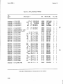
Table 6-2. REPLACEABLE PARTS
-hpStock
No.
0150-0012
0150-0082
0180-0032
0180-0049
0180-0502
Description'
C:
C:
C:
C:
C:
FxD,
FxD,
FxD,
FxD,
FxD,
CER.
CER.
ELECT.
ELECT.
ELECT.
0180-0131 C: FxD, ELECT.
0180-0518 C: FxD, ELECT.
0370-0133 KNOB-CURRENT LIMIT
0370-0137 KNOB-Voltage Adjust
0686-1025 R: FxD, Camp.
0686-1515 R' FxD. Camp
0683-0685 R: FxD. Compo
0686-3915 R: FxD, Compo
0686-3305 R: FxD, Camp.
0686-3335 R: FxD, Camp.
0686-7515 R: FxD, Camp.
0687-1021 . R: FxD, Camp.
0687-1531 R: FxD, Camp.
Mfr.
Mfr.Part.No.
TO
RS
0-01
8200
10
20
500
pF
,uF
,uF
pF
,uF
1000VDCW
500VDCW
10VDCW
50VDCW
29VDCW
56289
28480
56289
56289
28480
29C214A3
0150-0082
D 32877
D 33909
0180-0502
1
1
1
2
1
1
1
1
1
1
150
lOUO
pF
,uF
63VDCW
50VDCW
28480
28480
28480
28480
01121
01121
28480
01121
01121
01121
01121
01121
01121
0180-0131
0180-0518
0370-0133
0370-0137
EB-1025
EB-1515
0683-0685
EB-3915
EB-3305
EB-3335
EB-7515
EB-l021
EB-1531
1
2
1
1
2
1
1
2
1
1
2
1
2
1
1
1
1
1
1
1
1
1
1
1
1
1
1
150
68
390
33
33
750
1
15
K Q 5'10
K Q 5%
Q 5%
Q 5 0 /0
Q 5%
Q 5'10
Q10%
Q 10'10
K Q 10'10
Q 10'10
Q 10'10
Q 10'10
K Q 10'10
0.5 W
05W
0.25 W
0.5 W
0.5W
0.5 W
0.5W
0.5W
0.5 W
0687-2211
0687-2711
0687-2721
0687-3331
0687-3911
0687-3921
0687-1031
0678-6821
0689-4315
0690-3321
R:
R:
R:
R:
R:
R:
R:
R:
R:
R:
FxD,
FxD,
FxD,
FxD,
FxD.
FxD,
FxD,
FxD,
FxD,
FxD,
Camp.
Camp.
Camp.
Camp.
Camp
Compo
Camp.
Camp.
Camp.
Camp.
220
270
2.7
33
390
3.9
10
6.8
430
3.3
0.5 W
0.5W
0.5 W
0.5 W
Q 10'10 05 W
Q 10 % 0.5W
Ql0'lo0.5W
Q 10'10 0.5W
Q 5'101 W
Ql0'lo1 W
01121
01121
01121
01121
01121
01121
01121
01121
01121
01121
EB-2211
EB-2711
EB-2721
EB-3331
EB-3911
EB-3921
EB-1031
EB-6821
GB-4315
GB-3321
1
1.
1
2
1
1
2
1
1
1
1
1
1
1
1
1
1
1
1
1
0690-1011
0690-3921
0692-3615
0693-1021
0692-3315
R:
R:
R:
R:
R:
FxD,
FxD,
FxD,
FxD,
FxD,
Camp.
Camp.
Camp.
Camp.
Camp.
Q 10'10 1 W
100
3.9 K Q10'lo1 W
Q 5'10 2 W
360
1 K Q10'lo2 W
Q 5'10 2 W
330
01121
01121
01121
01121
01121
GB-1011
GB-3921
GB-3615
HB-1021
GB-3315
1
1
2
1
1
1
1
1
1
1
0760-0501
R: FxD, MET.FLM.
28480
0760-0501
K
K
K
K
1.3 K Q 2'10 1
W
1
• see List of Abbreviations in introduction to this section
I
!
I
Model 6960 A
Section VI
Table 6-2. REPLACEABLE PARTS (CO NT'D)
-hpStock
No.
,
"It
..
' ::;;
•
Description'
0813-0502
0813-0503
R: FxD
R: FxD
1120-0512
1120-0513
1 Q 5%
1.8 Q 5%
Mfr.
Mfr.Part.No.
TO
RS
28480
28480
0813-0502
0813-0503
1
2
1
1
Meter Volt
Meter Ampere
28480
28480
1120-0512
1120-0513
1
1
1
1
1251-0148
Connector - Power
OOOOU
H 1081-2
1
1
1400-0084
2140-0015
Fuseholder
Lamp- Neon
75915
342014
1
1
1
1
1510-0009
1510-0503
Binding Post Black
Binding Post Red
28480
28480
1510-0501
1510-0502
1
2
1
1
1850-0169
1850-0168
1850-0509
1851-0017
1901-0025
1901-0026
1901-0033
Transistor - Germanium
Transistor - Germanium
Transistor - Germanium
Transistor - Germanium NPN 2N 1304
Diode - Silicon
Diode - Silicon
Diode - Silicon
Diode - Zener
Diode - Zener
R:VAR. WW
10 K Q 20% 2 WLiN
R: VAR. Compo 250
Q 20% 2 WLiN
R: VAR. Compo
5K Q 20% 0.3W
10 K Q 20% 0.3W
R: VAR. Compo
2xl0 Q 10% 2 WLiN
R: VAR. WW
R:VAR.WW
10
Q 10% 0.5W
220 V: Fuse Cartridge 0.44 A, slow blow
110 V: Fuse Cartridge 0.8 A, slow blow
Switch - Slide
Switch - Push Button
Special Order: Power Cord, P2: Nema plug
Standard: Power P2: Schuko plug
Transformer - Power
28480
1850-0169
1850-0168
1850-0509
2N 1304
RD 1526
34531
IN485B
1902-0502
1902-0048
Type J
2100-0503
2100-0504
2100-0505
2100-0506
2100-0507
313.400
313.800
4633
3101-503
KH4147
8120-0100
9100-0513
1
2
1
4
4
13
2
1
1
1
1
1
1
1
2
1
1
1
1
1
1
1
1
2
1
4
4
13
1902-0048
1902-0057
2100-0234
2100-0503
2100-0504
2100-0505
2100-0506
2100-0507
2110-0019
2110-0020
3101-0033
3101-0503
8120-0078
8120-0100
9100-0513
WW
WW
2W
2W
28480
28480
01295
49956
02735
07910
28480
28480
01121
28480
28480
28480
28480
28480
75915
75915
42190
28480
70903
28480
28480
2
1
1
1
1
1
1
1
1
10
10
1
1
1
1
1
• see List of Abbreviations in introduction to this section
6·6
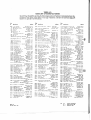
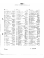
TABLE 6-3.
CODE LIST OF MANUFACTURERS
The following code numbers are from the Federal SUpply Code for Manufacturers Cataloging Handbooks H4-1
(Name to Code) and H4-2 (Code to Name) and their latest supplements. The date of revision and the date of the
supplements used appear at the bottom of each page. Alphabetical codes have been arbitrarily usigned to
suppliers not appearing in the H4 Handbooks.
Code
No.
Code
Manufacturer
Address
Any supplier of U. S.
00000 U. S. A. Common
Mount Holly Springs, Pa.
00136 McCoy Electronics
Rochester, N. Y
00213 Sage Electronics Corp
Danielson, Conn
00287 Cemco Inc
Colton, Calt!
00334 Hum Id,al
Valley Stream, N. Y.
00348 Mlcrotron Co., Inc.
00373 Garlock Inc.
Camden, N. J
Electronics products Dlv
New Bedford, Mass.
00656 Aerovox Corp
00779 4mp Inc
Harrisburg, Pa.
00781 AI/crilft RadiO Corp
Boonton, N. J.
00815 Northern Engineeling Laboratories, Inc.
Bu/linglon, WIS.
00853 Sangamo ElectriC Co
Pickens D,v.
Pickens. SC
00866 Goe Engineering Co
Los Angeles, Calif.
00891 Ca/I E, Holmes Corp
Los Angeles, Calt!.
00929 Mlclolab Inc.
LIVIngston, N J.
01002 General Electflc Co
Capacitor Dept.
Hudson Falls, N. Y.
B/ockton, Mass.
01009 Alden Ploducts Co
Milwaukee, Wis.
01121 Allen Bradley Co.
Beverly HillS, Calif.
01255 L ilton Industries, Inc.
Lawndale, Calif.
01281 TRW Sem Iconductors, Inc
01295 Texas Instruments, Inc.
Dallas, Texas
TranSistor Products D,v
AllIance, OhIO
01349 The Alliance Mfg. Co.
Van Nuys, Calif.
01589 Pacrf,c Relays, Inc.
01930 Amerock Corp.
ROCkford, '".
Santa Clala, Calli.
01961 Pulse EngineerIng Co.
Sauge/tles, N. Y.
02114 Ferroxcube Corp. of America
Long Branch, N. J.
02116 Wheelock Signals, Inc.
Sunnyvale, Calif.
02286 Cole Rubber and Plutlcs Inc,
Chicago, III,
02660 Amphenol·Bo/g Electronics COIP,
02735 RadiO Corp. of America, SemIconductor
and Materials D,v.
Somerville, N. J.
02771 Vocallne Co. of America, Inc.
Old Saybrook, Conn.
San Fe/nando, Calif.
02777 Hopkins Englneeflng Co.
03508 G, E. Sem Iconductor Prod. Dept. Syracuse, N. Y.
03705 Apex Machine & Tool Co.
Dayton, Ohio
03797 Eldema Corp.
Complon, Caltf.
03877 TranSit/on Elect/ic Co/p.
Wakefield, lIass.
Cedar Knolls, N. J.
03888 Py/ofihr Reslsto/ Co. Inc.
03954 SInger Co., Diehl Dlv.
Finderne Planl
SUllie/ville, N. J.
04009 Arrow, Halt and Hegeman Elecl. Co,
Hartford, Conn.
04013 Taurus Corp.
Lilli Dtrtville, II. J.
04222 HI·Q DiviSion of Aerovo~
Myrtle Beach, S. C.
04354 Precision Paper Tube Co.
Chicago, III.
04404 Dymec DIVISIOn of HeWlett-Packard Co.
Palo Alia, Calif.
04651 Sylvania ElectrIC Products, lIicloWlve
Device Dlv
1I0uniain View, Calif.
04713 1I0torola, Inc., SUlconductol Prod. Div.
PhoenIX, Alizona
04732 Flltron Co., Inc. Western Dlv.
Culver City, Calif.
04773 AutOllllllc Electric Co
1I0rlhlake, III.
04796 Seqvora Wire Co.
Redwood City, Calif.
04811 Precision Call Sprinl Co.
EI 1I0nte, Calif.
04870 P. II. Motor COllpuy
'estchester, III.
04919 COlllpollent Mfl. ServIce Co.
'. Bridlewattl, Mass.
05006 Twentieth Century Plashcs, Inc.
Los Anl.les, Calif,
05277 WeslinghOIlSl ElectriC Corp.
SUI I-Conductor Depl.
Younlwood, Pa.
05347 UIlIOlIll, Inc.
Su lIateo, Calif
No.
Manufacturer
05397
Union Carbide Corp., Linde D,v
05593
05616
05624
05728
05729
05783
05820
06004
06090
06175
06402
06540
06555
06666
06751
06812
06980
07088
07126
07137
07136
07149
07233
07261
07263
07322
07387
07397
07700
07910
07933
07980
08145
08289
08358
08524
08664
08717
08718
08792
08984
09026
09134
09145
09250
09569
10214
10411
10646
11236
11237
Adelrus
Kernel Dept.
Cleveland, OhiO
Illumilronic Englneellng Co
Sunnyvale, Calif.
Cosmo PlastiC
IC a Electflcal Spec. Co.)
Cleveland, Ohio
Barber Colman Co
Rockford, III.
Tilfen Optical Co
Roslyn Heights, Long Island, N. Y
Weslbury, N. Y.
Metro·Tel Corp
Stewarl EnglAeellng Co
Santa CIUZ, Calif.
Wakefield Englneeflng Inc.
Wakefreld, Mass.
Basslck Co. The
Brtdgepo/I, ConA.
Raychem Corp.
Redwood City, Calif,
Bausch and Lomb Optical Co.
Rochester, N. Y
Chicago, III.
E T. A. Ploducts Co. of Ameflca
Amatom ElectroAlc Hardware Co
Inc
New Rochelle. N. Y.
Beede Eleclflcal Instrument Co., Inc
Penacook, N. H
General DeVices Co., Inc
Indianapolis, lAd
Semcor Dlv. Components Inc.
PhoeniX. Artz,
TOlllngton Mfg. Co
West D,v.
Van Nuys. Calif
Varian Assoc. Elmac Dlv
San Carlos Calif,
KelVin Electm Co
Van Nuys, Calif.
Dlgdlan Co.
Pasadena, Calif.
TranSistor Elecl/onlcs Corp
IIlnneapolis, IIlnn,
Westlnahouse Electric Corp
EI.ctronic Tube Dlv.
Elmlla, N. Y
Ftimohm Corp.
New York, II. Y.
Clnch·Graphlk Co.
City of Industry, Calif.
Avnel Corp
Culver CIty, Calif.
Fairchild Camera & Inst Corp.
Semiconductor Dlv.
MountaIn View, Calif.
Minnesota Rubber Co
Minneapolis, lIinn.
Blrtcher Corp, The
Monteley Palk, Calif.
SylvanIa Elect. Prod. Inc., Mt. View Ope/atlons
lIounllln View, Calif.
Technical Wile Products Inc.
Clanford, II. J.
Continental DeVice Corp.
Hawthorne, Calif.
Raytheon IIfg. Co
Semiconductor D,v.
1I0uniain View, Calif.
Hewletl-Packald Co., Boonton Radio Oiv.
Rockaway, N, J,
U. S Engineering Co.
Los A.leles, Calif.
BIIlIn, Delberl Co.
POlllona, Calif.
Burgess Battery Co
Nla,ala Falls, OntarIO, Canada
Deutsch Fastener Corp.
Los An,eles, Calif,
BrIstol Co. The
Waterbury, Conn.
Sloan Company
Sun Valley, Calif.
ITT Cannon Electflc Inc. Phoenl~ Dlv.
PhoeniX, Arizona
CBS Electronrcs Semiconductor
Operations, Dlv of CBS. Inc.
Lowell, lIass,
Mel-Ratn
Illdiinapolis, Ind,
Babcock Relays Dlv
Costa lIesa, Calif.
Teus Capacitor Co
Houston, Telas
Alohm Electronics
Sun Valley, Calif.
Electro Asstflbllu, Inc.
Chic ala, III.
lIallo/y Battery Co of
Canada, LId.
Toronto, OntarIO, Canada
General TranSistor Western Corp.
Los Angeles, Calil.
TI-Tal Inc.
Berkeley, Calif.
Carborundum Co.
Nillara Falls, N. Y.
CTS of Berne, Inc.
Berne, Ind.
Chicago Telephone of California, Inc.
So. Pas.denl, Cali!.
Code
No.
Addrus
11242 Bay Slate ElecfronlCS Corp
Waltham, Mass
Microwave Dlv
11312 Teledyne Inc
Palo Alto Calif.
1 1534 Duncan Electronics Inc
Costa Mesa, Calif.
11711 General Instrument Corp
Semlconduclor
Dlv., PrOducts Group
Newark, N. J.
11717 Impe"al ElectroniC, Inc
Buena Park, Cllif.
Melabs,
Inc
11870
Palo Alto, Calif.
12136 Philadelphia Handle Co
Call1den, N. J,
12361 Grove IIfg Co., Inc.
Sh ady GlOve, Pa.
12574 Gullon Ind. Inc., CG Elecl. Dlv.
Albuquerque, N. M.
12697 ClarostafMfg Co.
Dovel, N. H.
127 28 Elmar Filter COlp.
'. Haven, Conn,
lid
1?859 Nippon ElectriC Co
Tokyo, Japan
12881 Metex Electronics Corp
Clark, N. J,
12930 Della Sem Iconductor Inc
Newporl BeaCh, Calif,
Dickson
Electronics
Corp.
12954
Scottsdale, Aflzona
13103 Thermo Iloy
Dallas, le~u
l3396 Telefunken (GmbH I
HIn ave/ , Gelm any
13835 Midland-Wright D,v of PaCifIC Industries, Inc.
Kansas CIty, Kansas
14099 Sem·Tech
lIewbu/y Park, Calil.
14193 Calif. Reslslor Corp.
Santa Monica, Calif.
14298 Amellcan Components, Inc
ConshOhocken, Pa.
14433 ITT SemIconductor, A D,v of Inl Telephone
& Telegraph Corp
West Palm Beach, Fla,
14493 Hewlett-Packald Company
Loveland, Colo.
14655 Cornell Dubller Elecfrlc Corp.
Newark, II, J,
14674 Corning Glass Walks
Cornlnl, N, Y.
14752 Electro Cube Inc.
So, Pasadena, Cali!.
14960 Wrlliams IIfg, Co
San Jose, CallI.
15203 Webster Elecllonlcs Co
NewYork,N.Y.
15287 SClonlcs COlp.
Northfld,e, Calif.
15291 Adjustable Bushing Co
N. Hollywood, Caltf.
15558 MIcron ElectronICs
Garden City, Lonltsl •• d, N. Y.
Lynblook, N. Y.
15566 Amprobe Inst. Corp.
Costa Mesa, Calif.
15631 Cabletronlcs
15772 Twenheth Century Coli Sprrng Co,
Santa CilIa, Calif.
15818 Alletco Inc.
lit. View, Calif.
t5909 Daven Dlv. Thomas A. EdlSon Ind.
IIcGlaw-EdlSon Co,
Lonl Island City, II, Y.
16037 Spruce Pine MIca Co.
Spruce Pine, N.C,·
16179 Ollnl·Spectla Inc.
Oetloil, III,
16352 Computer Diode Corp.
Lodi, N, J,
16688 Ideal Prec lIeter Co., InC,
De Jur lIeter DIV,
Blooklyl, N. Y,
Koko." lId.
16758 Delco RadiO Div, of G,M. Corp.
CanDia Park, Calif,
17109 Ther.onetlcs In.c.
17474 Tr;,"e~ Company
1I0untain Vi.w, Calif,
Akron, Ohio
17675 HamlIn lIelal Products Corp
110. Hollywood, Calif.
17745 Angstrohm Plec. Inc
Palo Alto, Calif.
18042 Power Deslln Paclfrc Inc
18083 Clevlte Corp. , Semlconductol Oiv.
Palo Allo, Calif.
18476 Ty-Car IIfg. Co., Inc.
Holliston, MaSl.
18486 TRW Elect. COlllp. ·OIV.
Des Plaines, III.
18583 Curtis Insl/ument, Inc.
Ittt. Kisco, N, Y.
18873 E. I. DuPon t an.d Co , Inc.
'iI.illlton, 0.1.
18911 Durant IIfg, Co,
Milwaukee, Wis.
19315 BendIX Corp, The
Ecllpse,Polneer Dlv.
TetllbolO, N. J.
19500 Thollln A. Edison Industries, D,v. of
McGraw·EdlSon Co.
'est Oranl', N.J,
Baldwin Park, Calif.
19589 Concoa
19644 LRC Eleclronics
Horseheads, N. Y.
Independence, KltSas
19701 Eleclra IIfg. Co
20183 General Allonlcs Corp.
Philad.lphia, Pa.
21226 Execulone, Iflc.
LOlli Islilld Cit" II. Y.
Frolll
00015-43
R.vised: May, 1961
Manufacturer
FSC.
H4-1
H4-2
Handbook Supple.tIIls
Oaled AUGUST 1966
Dat.d NOV 1"2
TAaLI6-3.
CODI LIST 0' MANUfACTURIRS (Cont'd)
Code
No.
Manufacturer
21335 Fafnlf Bearing Co . The
New Britain. Conn.
21520 Fansteel Melallurglcal Corp
N. Chicalo. III.
23783 British Radio ElectroniCS LId
Washinlton. D. C.
24455 G. E. Lamp DIvIsion
Nela Park. Cleveland. crhio
24655 General Radio Co.
West Concord, Mass.
26365 Gries Reproducer Corp.
New Rochelle. N. Y.
26462 Grobel File Co. of AmlHlca. Inc.
Carlsladt, N. J.
26992 Hamilton Watch Co.
Lancaster, Pa.
28480 Hewlet/-Packard Co.
Palo Alto. Calif.
Kenilworth, N. J.
28520 Heyman Mfg. Co.
33173 G. E RecelVlng Tube Depl.
Owensbolo, Ky.
35434 Lectrohm Inc
ChicalO, III.
Stanwyck
Coil
Products
LId.
36196
Hawkesbury, Ontario, Canada
36287 Cunningham. W. H. & HIli, LId.
Toronto Ontario, C.nada
37942 P. R. Mallory & Co. Inc.
Indlan.polis, Ind.
MechanICal
Indusll/es
Prod.
Co.
39543
Akron, Ohio
40920 M,nlalure PreCIsion Bearings. Inc.
Keene, N. H.
42190 Muler Co
Chicago, III.
43990 C. A. Norgren Co
Englewood, Colo.
44655 Ohmlte MIg Co
Skokre, III.
46384 Penn Eng. & Mfg Corp.
Doyleslown, Pa.
47904 PolarOid Corp
CIllIbridge, Mass.
48620 PreCISion Thermometer & Insl. Co.
Southalllpton. Pa.
49956 Microwave & POWeI Tube Dlv.
Wallha•• Mass.
52090 Rowan Controller Co.
Westminster. Md.
52983 Sanboln Company
Walthalll, Mass.
54294 ShallclosS MIg Co
Selma, N. C.
ChlcalO, III.
55026 Simpson Electllc Co
55933 Sana lone COIP
Elmsford, N. Y.
55938 Raytheon Co. Commerc,al Apparalus &
Systems Dlv
So. Norwalk. Conn.
56137 Spaulding Fibre Co
Inc
Tonawanda. N. Y.
56289 Sprague Electric Co.
North Adams, Mass.
59446 Telex Inc
SI. Paul, Minn.
59730 Thomas & Belts Co
Elizabeth, N. J.
60741 Triplett Electrical Inst Co.
Bluffton. OhiO
61775 Union Swtlch and Signal. Dlv. of
Westinghouse Air Brake Co
Plltsbu1lh, Pa.
62119 universal Eleclrlc Co
Owosso. Mich.
63743 Ward·Leonard Eleclrlc Co
MI. Vernon. N. Y.
64959 Western ElectriC Co., Inc.
New York, N. Y.
65092 Weston 11151. Inc. Weston·Newark
Newark. N. J.
66295 W,ttek MIg Co
ChlcalO, III.
66346 Revere Wollansak Dlv Minn. Mining &
Mfg. Co.
SI. Paul. Minn.
70276 Allen Mig Co
Hartford, Conn.
New York, N. Y.
70309 Allied Conlrol
70318 Allmetal Screw Product Co
Inc.
Gilden City. N. Y.
70485 AtlantiC India Rubber Works. Inc.
Chica,o, Ill.
70563 Ampelite Co .. Inc
Union Cily. N. J.
Minneapolis. Minn.
70674 AOC Producls Inc.
70903 Belden Mfg Co.
Chicago, lit.
70998 BHd Eleclronlc COlp.
Cleveland, Ohio
71002 Blrnbach RadiO Co
New York. N.Y.
71041 Basion Gear Works Dlv of Murray Co.
01 Texas
QUIncy, Mass.
71218 Bud RadiO. Inc
'rlloughby, Ohio
71286 Cam lac Fastenel Corp
Paramus. N. J.
71313 Cardwell Condensel Corp
lindenhurst L I. ,N. Y.
71400 Bussmann Mfg. Drv. 01 McGraw·Edlson Co.
SI. Louis. Mo.
Chicago, III.
71436 Chicago Condenser Corp
Plco·Rivera, r..li!.
71447 .Cal". Spring Co . Inc
Code
No.
71450 CTS Corp.
Elkharl. Ind.
71468 ITT Cannon Electllc Inc.
Los Angeles, Calif.
71471 CInema. Dlv. Aerovox Corp.
Burbank, Calif.
71482 C P Clare & Co.
Chicago. III.
71590 Centralab Dlv. of Globe Union Inc
Milwaukee, .is.
71616 CommerCial PlastiCS Co.
ChlcalO. III.
71700 CornIsh Wire Co .. The
New York, N. Y .
71707 Coto Corl Co
Inc
Providence, R.1.
71744 Chicago "'Inralure Lamp Works
Chicago, III,
71753 A.O. Smith Corp
Crowley OIV
West Orange, N. J.
71785 Cinch Mfg. Co., Howard B. Jones Dlv.
Chlcalo. III.
71984 Dow Corning Corp.
Midland. MIch.
72136 Eleclro Motive Mig Co ,Inc
Wlllimanltc, Conn.
72354 John E. Fast Co. Dlv. Vlctoreen Inslr. Co.
ChlCleO, III.
72619 Dlalight Corp.
Brooklyn, N. Y.
72656 Indiana General Corp. Eleclronlcs Dlv.
Keasby, N.J.
72699 General Instrument Corp. Cap. Div. Newark, N. J.
72765 Drake Mfg Co.
ChIcago, III.
72825 Hugh H. Eby Inc.
Phrladelpnla. Pa.
72928 Gudeman Co
Chicago, III.
72964 Roberl M. Hadley Co.
Los Angeles, Calif.
72982 Erre Technological Producls. Inc.
Elle, Pa.
73061 Hansen Mfg. Co .. Inc.
Pllncelon, Ind.
73076 H. M. Harper Co
Chicago, Ill.
73138 Hel,pol Dlv. of Beckman Inst. Inc.
Fullerton, Cali!.
73293 Hughes Products DIVISIon of HUlhes
Alrclal t Co
Newport Beach, Calif.
73445 Amperex Eleclronlc Co., Dlv. of North Allleric.n
Phillips Co., Inc.
Hicksville, N. Y.
73506 Bradley Semiconductor Corp
New Hayen, Conn.
73559 Carltng Eleclrlc, Inc
Harlfo/d, Conn.
Trenton, N. J.
73586 Circle F Mfg. Co.
73682 George K Garrell Co .• DIY. MSL
Industries Inc
Philadelphi., Pa.
73734 Federal Screw Products Inc.
Cbicalo, III.
73743 Fischer Specill MIg. Co.
Cincinnati, Ohio
73793 General Industries Co., The
Elyria, Ohio
73846 Goshen Siampln, & Tool Co.
Goshen, Ind.
13899 JFD ElectronICs Corp.
Brooklyn, N, Y.
13905 Jennings RadiO Mfe. Corp.
San Jose, Calif.
74276 Sllnait Ie Inc.
N.plune. N. J.
Winchester, Mus.
14455 J. H. Wlnns, and Sons
74861 Industrial Condenser Corp.
Chicaeo, Ill.
14868 R, F, Products DIVISion 01 A.phenol-Bor,
ElectronICs Corp.
Danbury, Conn.
74910 E. F. Johnson Co.
Wu.ca, Minn.
75042 Inte/natlonal ResIstance Co.
Philadelphi •• Pa.
15378 CTS Knighls Inc.
S.ndwich, III.
MI. Vernon, N. Y.
75382 Kulka Electric Corporalton
75818 Lenz Eleclric Mfl. Co.
Chic'go, III.
75915 Lilllefuse. Inc.
On Plaints, III.
76005 Lord MIg. Co.
Erie, P•.
16210 C. W. Ma/wedel
San Francisco, Calif.
76433 General Insirulllent Corp., Micarnold Division
Newark. N.J.
76487 James Millen Mfg. Co., Inc.
M.lden, Mus.
76493 J. W, Miller Co.
Los Anl.lts, Calif.
16530 CInch·Monadnoc k, Dlv. of UnIted Carr
Futener Corp.
San Lundro, Calif.
76545 Mueller Eleclric Co.
Clev.land. Ohio
76703 National Union
Newark, N.J.
76854 Oak Manufaclullng Co.
Crysl.1 Lak., III.
77068 BendiX Corp., The
BendiX PaCifiC Dlv.
N. Hollywood, Calif.
From:
00015-43
ReVised: May, 1967
Manufacturer
.77015 Pacdlc Metals Co.
San Francisco, Calif.
77221 Phanostran Instruunt and Electronic Co.
SOlIlh Pasad.na, Calif.
77252 Phrladelphla Sleel and Wire Corp.
Philadelphia, P,.
77342 Amerrean Machine & Foundry Co. Poller
& Brumfield Dlv.
Princ.lon, Ind.
77630 TRW Eleclronic COlllponents Dlv.
Call1den, N. J.
77638 General Insirulllent Corp., Rectifier Div.
Brooklyn, N. Y.
77764 ReSistance Products Co.
Harrisburg, P,.
77969 Rubbercrafl Corp. of Calif.
Torrance, Calif.
78189 Shakeproof DIVision of IllinOIS Tool Works
El,il, III.
78283 SIgnal Indicator Corp.
Nlw York, N. Y.
78290 Stluthers·Dunn Inc.
Pit.. n, N.J.
78452 Thompson-Bremer & Co.
Chlcagl, III.
78471 TIlley Mfg. Co.
San FrlnCISCO, Calif.
78488 Slackpole Carbon Co.
SI. Ma/ys, P•.
78493 Standard Tholllson Corp.
Wallh'lII, Mass.
Tinnerlllan
Products,
Inc.
78553
Clnelud, Ohio
78790 Translormer Enlinurs
San Gab/iel, C.lif.
78947 UClnite Co.
New.lonville, Mass.
79J36 Waldes Kohinoor Inc.
Lon, Island City, N. Y.
79142 Veeder Rool, Inc.
Harllord, Conn.
79251 'enco Mfg. Co.
Chica,o, III.
79727 Conhnenlal·Wirl Eleclronlcs Corp.
Philadelphia, Pa.
79963 Zrerlck Mf,. Corp.
New Rochelle. N. Y.
80031 Mepco DiVISIon of Sessions Clock Co.
Morrrstown, N. J.
80120 Schnilzer Alloy Products Co.
Elizabelh, N. J.
80131 ElectronIc Industlles ASSOCiation. Any brand
Tube mee"nl EIA Standards·Washinglon, DC.
80207 Unlnux SWitch, Dlv. Maxon Eleclronlcs Corp.
'allilll'ord, Conn.
80223 United Transformer Corp
New York, N. Y.
80248 Oxford Eleclrlc Corp.
Chicago, III.
80294 Bourns Inc.
Riverside. Calif.
80411 Acro Dlv. of Robertshaw Conlrols Co.
ColulIIbus, Ohio
80486 All Slar Products Inc.
Defilnce, Ohio
80509 Avery Adhesive Label Corp.
Monrovia, C.lif.
80583 Hammarlund Co., Inc.
N.w York, N. Y.
80640 Slevens. Arnold, Co., Inc.
Boslon, Mus.
81030 Inlernatronal IOSlrullltnls Inc.
Or.nge, Conn.
81073 Grayhill Co.
LaGr.ng_, III.
81095 Tllad Transforllltr Corp.
Venice, Calif.
81312 'Inchester Elec. Dlv. Lillon Ind .• Inc.
OakYille, Conn.
81349 Military SpeCification
81483 Internatronal Rectrfier Corp.
EI Se,undo, Calif.
Cambridge, lIIus.
81541 Allpax Eleclronics, Inc.
81860 Barry Conlrols, Dlv. Barry 'rlghl Corp.
Walertown, Mus.
82042 Carter PreciSion ElectriC Co.
Skokie, III.
82047 Sperll F.raday Inc .• Copper HeWitt
ElectriC Dlv.
Hoboken, N. J.
82142 Jeffers Eleclronlcs DIVISIon of Speer
Carbon Co.
Du Bois. Pa.
82170 Faffchlld Call1tra & Insl. Corp.
Defense Prod. DIvision
Clifton, N. J.
82209 Magutre Industlles, Inc.
G,eenwich, Conn.
Sylvania
Eleclrlc
Prod.
Inc.
82219
Electronic Tube DIVision
ElIIporrum, Pa.
Easl Newark, Hallison, N, J,
82376 Astron Corp.
Chic.go. III.
82389 SWllchcraft, Inc.
82647 Metals & Controls Inc. Spencer Producls
AIII.boro, Mass.
82768 Phillips-Advance Conlrol Co.
Joli." lit.
FSC.
H4-1
H4-2
H.ndbook Suppl •• enls
Daled AUGUST J966
Datld NOV. 1962
-
HEWLETT$~PACKARD
_
GmbH
MANUAL CHANGES
MOD E L
DC
POWER
6 9 6 0
A
SUPPLY
Manual Serial Prefixed:
Manual Printed:
AUG.
6041967
To adapt this manual to instruments with other serial prefixes check for errata
below, and make changes shown in tables.
Instrument Serial Prefixes
G-604and above
Make Manual Changes
ERRATA: In Table 1-1, Specifications:
Delete: "Meters on Option 01 only".
In Section VI, Replaceable Parts:
-hp- Stock No.
Change: C9 to C9* C:fxd., cer. (preferred value 0.0082uF,500VDCW) 0150-0082
R5
R:fxd., to 330 Ohm, +5%, 2W
0692-3315
R6
R:fxd., to 360 Ohm, +5%, 2W
0692-3615
R43 to R43 *
R:fxd., compo (preferred value 6.8 Ohm,
+5%, 0.25W)
0683-0685
the "Reference Des ignator" of 52 to S\~2
Add:
R44
R:fxd., 47 Ohm, 0.25W, +5%
0684-4701
(connected in series with CR13)
In Section V, Figure 5-4, Circuit Diagram:
Add:
R43*
(connected in series with CR16,17;
part may be omitted).
Jan. 29, 1968
9320-0535
Page
HEWLETT
iii
PACKARD
ELECTRONIC INSTRUMENTATION SALES AND SERVICE
UNITED STATES
ALABAMA
PO- Box 4207
2003 Byrd Spring Road S.W
Huntsville 35802
Tel ,2051 881-4591
TWX 810·726·2204
ARIZONA
3009 North Scottsdale Road
Scottsdale 85251
Tel: (602) 945-7601
TWX: 910-9'!i0-1282
232 South Tucson Boulevard
Tucson 85716
Tel: (6021 623·2564
TWX: 910-952-1162
CALIFORNIA
3939 Lankershim Boulevard
North Hollywood 91604
Tel: (213) 877-1282
TWX: 910-499-2170
1101 Embarcadero Road
Palo Alto 94303
Tel: (415) 327-6500
TWX: 910-373-1280
2591 Carlsbad Avenue
Sacramento 95821
Tel: (9161482·1463
TWX: 910-367-Z092
1055 Shafter Street
San Diego 92106
Tel: (714) 223-8103
TWX: 910-335-2000
COLORADO
7965 East Prentice
Englewood 80110
Tel: (303) 771-3455
TWX: 910-935-0705
CONNECTICUT
508 Tolland Street
East Hartford 06108
Tel 1203 289-9394
TWX: 710-425·3415
ILLINOIS
5500 Howard Street
Skokie 60076
Tel: '312, 677-0400
TWX 910·223-3613
MISSOURI
9208 Wyoming Place
Kansas City 64114
Tel 1816: 3332445
TWX 910·771-2087
111 East Avenue
Norwalk 06851
Tel: 1203\ 853-1251
TWX: 710·468·3750
INDIANA
4002 Meadows Dnve
Indianapolis 46205
Tel i317, 546·4891
TWX: 810-341·3263
2812 South Brentwood Blvd.
St. Louis 63144
Tel 1314' 6440220
TWX 910·760·1670
DELAWARE
3941 Kennett Pike
Wilmington 19807
Tel 13021655-6161
TWX: 510-666-2214
LOUISIANA
PO. Box 856
1942 Williams Boulevard
Kenner 70062
Tel ,5041 721·6201
TWX: 810-955-5524
NEW JERSEY
391 Grand Avenue
Englewood 07631
Tel: (201' 567-3933
TWX: 710·991·9707
FLORIDA
Suite 106
9999 N.E. 2nd Avenue
Miami Shores 33138
Tel: (305) 758-3626
TWX: 810-848·7262
MARYLAND
6707 Whitestone Road
Baltimore 21207
Tel: (301) 944-5400
TWX 710-862-0850
P.O. Box 20007
Herndon Station 32814
621 Commonwealth Avenue
Orlando
Tel: 1305) 841·3970
TWX: 810-850-0113
P.O. Box 8128
Madeira Beach 33708
410 150th Avenue
St. Petersburg
Tel: (813! 391·0211
TWX: 810-863-0366
GEORGIA
P.O. Box 28234
2340 Interstate Parkway
Atlanta 30328
Tel: (4041 436-6181
TWX: 810-766-4890
PO Box 727
Twinbrook Station 20851
12303 Twinbrook Parkway
Rockville
Tel ,301: 427·7560
TWX 71 0-828-9684
MASSACHUSETTS
Middlesex Turnpike
Burlington 01803
Tel 161 n 272-9000
TWX 710-332·0382
MICHIGAN
24315 Northwestern Highway
Southfield 48075
Tel: (313) 353-9100
TWX: 810-232-1532
MINNESOTA
2459 University Avenue
St. Paul 55114
Tel: (612) 645-9461
TWX: 910-563-3734
NEW MEXICO
P.O. Box 8366
Station C 87108
6501 Lomas Boulevard N.E
Albuquerque
Tel: (505; 255·5586
TWX: 910·989-1665
156 Wyatt DrIVe
Las Cruces 88001
Tel: ,505, 526·2485
TWX 910·983·0550
NEW YORK
1702 Centra I Avenue
Albany 12205
Tel 15181869-8462
1219 Campville Road
Endicott 13760
Tel: (607) 754-0050
TWX: 510·252·0890
236 East 75th Street
New York 10021
Tel: 12121879-2023
TWX: 710-581-4376
82 Washington Street
Poughkeepsie 12601
Tel: (914: 454-7330
TWX 510-2480012
39 Saginaw Drive
Rochester 14623
Tel: (716) 473·9500
IWX 510-253-5981
1025 Northern Boulevard
Roslyn, Long Island 11576
Tel: i5161 869·8400
TWX 510·223-0811
5858 East Molloy Road
Syracuse 13211
Tel: (315) 454-2486
TWX: 710-541-0482
NORTH CAROLINA
P.O. Box 5187
1923 North Main Street
High Point 27262
Tel: (919! 882-6873
TWX: 510-926-1516
OHIO
5579 Pearl Road
Cleveland 44129
Tel: 1216! 884-9209
TWX: 810-421-8500
2460 South Dixie Drive
Dayton 45439
Tel: (513) 298-0351
TWX: 810-459-1925
OREGON
Westhills Mal" Suite 158
4475 S.W. Scholls Ferry Road
Portland 97225
Tel (503) 292-9171
TWX: 910-464-6103
PENNSYLVANIA
2500 Moss Side Boulevard
Monroeville 15146
Tel 1412> 271·0724
TWX 710-797·3650
144 Elizabeth Street
West Conshohocken 19428
Tel 1215) 248·1600, 828·6200
TWX: 510·660-8715
TEXAS
PO. Box 7166
3605 Inwood Road
Dallas 75209
Tel: (2141 357-1881
TWX: 910-861-4081
P.O. Box 22813
4242 Richmond Avenue
Houston 77027
Tel: (7131 667-2407
TWX: 910·881·,2645
GOVERNMENT CONTRACT OFFICE
225 Billy Mitchell Road
San Antonio 78226
Tel: (5121434-4171
TWX: 910-871-1170
UTAH
2890 South Main Street
Salt Lake City 84115
Tel: (801) 486-8166
TWX: 910-925-5681
VIRGINIA
P.O. Box 6514
2111 Spencer Road
Richmond 23230
Tel: (703) 282-5451
TWX: 710-956-0157
WASHINGTON
11656 N.E. Eighth Street
Bellevue 98004
Tel: (206) 454-3971
TWX: 910-443-2303
FOR AREAS NOT LISTED, CONTACT: Hewlett-Packard; 1501 Page Mill Road, Palo Alto, Californ ia 94304, Tel: (4151326-7000, TWX: 910-~73-1267. Telex: 34-8461
CANADA
ALBERTA
10010 - 105th Street
Edmonton
Tel: (403) 424-0718
TWX: 610-831-2431
BRITISH COLUMBIA
Hewlett-Packard (Canada) Ltd
2184 West Broadway
Vancouver
Tel: (604) 738-7520
TWX: 610-922-5050
NOVA SCOTIA
7001 Mumford Road
Suite 356
Halifax
Tel: (902) 455-0511
TWX: 610-271-4482
ONTARIO
Hewlett-Packard (Canada' Ltd.
&80 Lady Ellen Place
ottawa 3
Tel: (613) 722-4223
TWX: 610-562-1952
Hewlett-Packard (Canada) Ltd.
1415 Lawrence Avenue West
Toronto
Tel: (4161 249-9196
TWX: 610-492-2382
QUEBEC
Hewlett-Packard (Canada) Ltd.
275 Hymus Boulevard
Pointe Claire
Tel: (514) 697-4232
TWX: 610-422-3022
Telex: 01-2819
FOR AREAS NOT LISTED, CONTACT: Hewlett-Packard Inter-Americas: 1501 Page Mill Road, Palo Alia. Calif. 94304, Tel: (4151326-7000, TWX: 910·373-1267, Telex: 034-8461; Cable: HEWPACK Palo Alto
CENTRAL AND SOUTH AMERICA
ARGENTINA
Mauricio A. Suarez
Te lecomunicaciones
Carlos Calvo 224
Buenos Aires
Tel: 30-6312, 34-9087
Cable: TELEPILOT Buenos Aires
CHILE
Hector Calcagni
Casilla 13942
Santiago
Tel: 490.505. 393.119
BRAZIL
Ciental, Importacao e
Comercio Ltda.
Avenida 13 de Maio, 13-22' andar
Rio de Janeiro G.B.
Tel: 42-9483
COLOMBIA
Instrumentacion
Henrik A. Langebaek & Cia Ltda.
Cra. 7A N" 48-51 i59
Apartado Aereo 6287
Bogota, 1 D.E
Tel: 45-78-06. 45-55-46
Cable: AARIS Bogota
Ciental, Importacao e
Comercio Ltda
Rua Des. Eliseu Guilherme, 62
Sao Paulo 8
Tel· 70-2318
Cable: CIENTALCO, Sao Paulo
COSTA RICA
Lic. Alfredo Gallegos Gurdian
Apartado 3243
San Jose
Tel: 21-86-13
Cable: GALGUR San Jose
ECUADOR
Laboratorios de Radio·lngenieria
Calle Guayaquil 1246
Post Office Box 3199
Quito
Tel: 12496
Cable: HORVATH Quito
EL SALVADOR
Electromca
27 Avenida Norte 1133
Apartado Postal 1589
San Salvador
Tel 25-74-50
Cable: ELECTRON ICA
San Salvador
GUATEMALA
Olander Associates Latin America
Apartado 1226
7a. Calle, 0-22, Zona I
Guatemala City
Tel 22812
Cable: OLALA Guatemala City
MEXICO
Hewlett-Packard Mexicana,
S.A. de C.V.
Eugenia 408. Dept. 1
Mexico 12, D.F.
Tel: 43·03-79
NICARAGUA
Roberto Teran G.
Edificio Teran
Apartado Postal 689
Managua
Tel 3451, 3452
Cable: ROTERAN Managua
PANAMA
Eleclr6nica Balboa, S.A.
PO Box 4929
Ave Manuel Espinosa No. 13-50
Bldg Alina
Panama City
Tel: 30833
Cable: ELECTRON Panama City
PERU
Fernando Ezeta B.
Av. Petit Thouars 4719
Miraflores
Casilla 3061
Lima
Tel: 50346
Cable: FEPERU lima
URUGUAY
Pablo Ferrando
SA Comercial e Industrial
Avenida Italia 2877
Casilla de Correo 370
Montevideo
Tel: 40-3102
Cable: RADIUM Montevideo
PUERTO RICO
San Juan Electronics, Inc.
P.O. Box 5167
Ponce de Leon 150. Stop 3
Puerta de Tierra Santa
San Juan 00906
Tel: (809) 725-3342
Cable: SATRONICS San Juan
VENEZUELA
Citec, C.A.
Edif. Arisan-Of. ::'t4
Avda. FranCISco de Miranda
Apartado del Este 10934 Chacaito
Caracas
Tel: 71.88.05
Cable: CITECAL Caracas
FOR AREAS NOT LISTED, CONTACT: Hewlett-Packard Inter-Americas, 1501 Page Mill Road, Palo Alte, Calif. 94304, Tel: [4151326-7000, TWX: 910-373-1267, Telex: 034-8461, Cable: HEWPACK Palo Alto
5/67
HEWLETT"" PACKARD
ELECTRONIC INSTRUMENTATION SALES AND SERVICE
EUROPE
AUSTRIA
Unilabor H.m.b.H.
Wissenschaftliche Instrumente
Rummelhardtgasse 6/3
P.O. Box 33
Vienna IX/71
Tel: 426 181
Cable: LABOR INSTRUMENT
Vienna
BELGIUM
Hewlett-Packard Benelux S.A.
~~:S:e~~e de I'Hopital
Te I : 11 22 20
Cable: PALOBEN Brussels
ENMARK
ge Ol~en tiS
nnega e
Copenhagen 0
Tel: 29 48 00
Cable: TOCOPEN Copenhagen
FINLAND
INTO O/Y
Meritullinkatu 11
P.O. Box 10153
Helsinki 10
Tel: '61 133
Cable: INTO Helsinki
FRANCE
Hewlett-Packard France
2 rue rete d'Or
Lyon, 6 - Rhone
Tel: 52 35 66
Hewlett-Packard Vertriebs-GmbH
Kurhessenstrasse 95
6 Frankfurt 50
Tel: 52 00 36
Cable: HEWPACKSA Frankfurt
Hewlett-Packard France
150 Boulevard Massena
Paris 13e
Tel: 707 97 19
Cable: HEWPACK Paris
GERMANY
Hewlett-Packard Vertriebs-GmbH
Lietzenburger Strasse 30
1 Berlin W 30
Tel: 248636
Hewl~tt-Packard Vertriebs-GmbH
Beim Strohhause 26
2 Hamburg 1
Tel: 24 05 51/52
Cable: HEWPACKSA Hamburg
Hewlett-Packard Vertriebs-GmbH
Reginfriedstrasse 13
8 Munich 9
Tel: 69 51 21/22
Cable: HEWPACKSA Munich
Hewlett-Packard Vertriebs-GmbH
Herrenberger Strasse 110
703 Boblingen, Wiirttemberg
Tel: 07031-6971
Cable: HEPAG Boblingen
GREECE
Kostos Karayannis
18, Ermou Street
Athens 126
Tel: 230 301
~~~~~~~~~~tra;:seV~~triebS-GmbH
Cable: RAKAR Athens
4 DUsseldorf 1
Tel: 68 52 58/59
IRELAND
Hewlett-Packard ltd.
224 Bath Road
Slough, Bucks, England
Tel: Slough 28406-9, 29486-9
Cable: HEWPIE Slough
ITALY
Hewlett-Packard !taliana S.p.A.
Viale Lunigiana 46
Milan
Tel: 69 15 84
Cable: HEWPACIT Milan
Hewlett-Packard Italiana S.p.A.
Palazzo Italia
Piazza Marconi 25
Rome _Eur
Tel: 591 2544
Cable: HEWPACIT Rome
NETHERLANDS
~:w~~~i~:~~a~~4~enelux,
N.V.
Amsterdam, Z.2
Tel: 42 77 77
Cable: PALO BEN Amsterdam
NORWAY
Morgenstierne & Co. A/S
Ingeniofirma
~s%essels Gate
Tel: 20 16 35
Cable: MOROF Oslo
PORTUGAL
Telectra
Rua Rodrigo da Fonseca 103
P.O. Box 2531
Lisbon 1
Tel: 68 60 72
Cable: TELECTRA Lisbon
SWITZERLAND
HEWPAK AG
Zurcherstra sse
8952 Schlieren
Zurich
Tel: (051) 98 18 21
Cable: HEWPACKAG Zurich
SPAIN
Ataio Ingerieros
Urgel, 259
Barcelona, 11
Tel: 230-69-88
Ataio Ingenieros
Enrique Larreta 12
Madrid, 16
TURKEY
Telekom Engineering Bureau
P.O. Box 376 - Galata
Istanbul
Tel: 49 40 40
Cable: TELEMATION Istanbul
Tel: 235 43 44 0
d'd
Cable: TELEATAI Ma rt
SWEDEN
HP Instrument AB
Hagakersgatan 7
Molndal
Tel: 031 _ 27 68 00
HP Instrument AB
Centralvagen 28
Solna
Tel: 08 - 83 08 30
Cable: MEASUREMENTS
Stockholm
UNITED KINGDOM
Hewlett-Packard Ltd.
224 Bath Road
Slough, Bucks
Tel: Slough 28406-9, 29486-9
Cable: HEWPIE Slough
YUGOSLAVIA
Belram SA
83 avenue des Mimosas
Brussels 15, Belgium
Tel: 35 29 58
Cable: BELRAMEL Brussels
FOR AREAS NOT LISTED, CONTACT: Hewlett-Packard S.A.; 54 Route des Acacias; Geneva, Switz.erland; Tel: (022) 42 81 50; Telex: 2.24.86; Cable: HEWPACKSA Geneva
AFRICA, ASIA, AUSTRALIA
AUSTRALIA
Hewlett-Packard Australia
Pty. Ltd.
22-26 Weir Street
Glen Iris, S. E. 6
Victoria
Tel: 20-1371 (4 lines)
Cable: HEWPARD Melbourne
Hewlett-Packard Australia
Pty. Ltd.
4 Grose Street
Glebe, New South Wales
Tel: 211-2235, 211-2888
Cable: HEWPARD Sydney
nON
ited Electricals Ltd.
P.O. Box 681
Yahala Building
Staples Street
COlombo 2
Tel: 5496
Cable: HOTPOINT Colombo
ETHIOPIA
African Salespower & Agency
Private Ltd., Co.
P. O. Box 718
Addis Ababa
Tel: 44090
Cable: ASACO Addisababa
HONG KONG
Schmidt & Co. (Hong Kong) Ltd.
P.O. Box 297
1511, Prince's Building
10, Chater Road
Hong Kong
Tel: 240168, 232735
Cable: SCHMIDTCO Hong Kong
INDIA
The Scientific Instrument
Co., Ld.
6, Tej Bahadur Sapru Road
Allahabad 1
Tel: 2451
Cable: SICO Allahbad
The Scientific Instrument
Co., Ld.
240, Dr. Dadabhai Naoroji Road
Bombay 1
Tel: 26-2642
Cable: SICO Bombay
The Scientific Instrument
Co., Ld.
11, Esplanade East
Calcutta 1
Tel: 23-4129
Cable: SICO Calcutta
The Scientific Instrument Co., Ld.
30, Mount Road
Madras 2
Tel: 86339
Cable: SICO Madras
The Scientific Instrumenteo., Ld.
B-7, Ajmeri Gate Extn.
New Delhi 1
Tel: 27-1053
Cable: SICO New Delhi
IRAN
Telecom, Ltd.
P. O. Box 1812
Teheran
Tel: 43850, 48111
Cable: BASCOM Teheran
ISRAEL
Electronics & Engineering
Div. of Motorola Israel Ltd.
16, Kremenetski Street
Tel-Aviv
Tel: 35021/2/3
Cable: BASTEL Tel-Aviv
JAPAN
Yokogawa-Hewlett·Packard Ltd.
Shinhankyu Building
No.8, Umeda
Kita-ku, Osaka City
Tel: 0726-23-1641
Yokogawa-Hewlett-Packard Ltd.
Ito Building
No. 59, Kotori-cho
Nakamura-ku, Nagoya City
Tel: 551-0215
Yokogawa-Hewlett-Packard Ltd.
OtiastliBqilding
No.59,I-chome, Yoyogi
ShibuYa-ku, Tokyo
TeE 370.2281
Cable:YOKOHEWPACK Tokyo
Telex: 232-2034
NEW ZEALAND
Sample Electronics (N.Z.) Ltd,
8 Matipo Street
Onehunga SE. 5
Auckland
Tel: 667-356
Cable: ELPMAS Auckland
KENYA
R. J. Tilbury Ltd.
P. O. Box 2754
Suite 517/518
Hotel Ambassadeur
Nairobi
Tel: 25670, 26803, 68206
Cable: ARJAYTEE Nairobi
KOREA
American Trading Co., Korea, Ltd,
Seoul P. O. Box 1103
112-35 Sokong-Dong
Jung-ku, Seoul
Tel: 3.7049, 3.7613
Cable: AMTRACO Seoul
LEBANON
Constantin E. Macridis
Clemenceau Street
Clemenceau Center
Beirut
Tel: 220846
Cable: ELECTRONUCLEAR Beirut
MALAYSIA
MECOMB Malaysia Ltd.
2 Lorang 13/6A
Section 13
Petaling Jaya, Selangor
Cable: MECOMB Kuala Lumpur
PAKISTAN (EAST)
Mushko & Company, Ltd.
31, Jinnah Avenue
Dacca
Tel: 80058
Cable: COOPERATOR Dacca
PAKISTAN (WEST)
Mushko & Company, Ltd.
Oosman Chambers
~~~~o:~f :oad
Tel: 51027, 52927
Cable: COOPERATOR Karachi
SINGAPORE
Mechanical and Combustion
Engineering Company Ltd.
9, Jalan Kilang
Singapore, 3
Tel: 642361-3
Cable: MECOMB Singapore
SOUTH AFRICA
F. H. Flanter & Co. (Pty.), Ltd.
Rosella House
Buitencingle Street
Cape Town
Tel: 3-3817
Cable: AUTOPHONE Cape Town
F. H. Flanter & Co. (Pty.), Ltd.
104 Pharmacy House
80 Jorissen Street
Braamfontein, Johannesburg
Tel: 724-4172
TAIWAN
Hwa Sheng Electronic Co., Ltd
P. O. Box 1558
21 Nanking West Road
Taipei
Tel: 46076, 45936
Cable: VICTRONIX Taipei
THAILAND
The International
Engineering Co., Ltd.
P. O. Box 39
614 Sukhumvit Road
Bangkok
Tel: 913460-1-2
Cable: GYSOM Bangkok
VIETNAM
Landis Brothers and Company,
Inc.
P.O. Box H-3
216 Hien-Vuong
Saigon
Tel· 20.805
Cable, LANBROCOMP Saigon
FOR AREAS NOT LISTED, CONTACT: Hewlett-Packard Export Marketing; 1501 Page Mill Road; Palo Alto, California 94304; Tel: (415) 326-7000; Telex: 0348461: Cable: HEWPACK Palo Alto
5/67
li
r-------HEWLETT
PACKARD - - - - - - - .
CERTIFICATION
Hewlett-Packard certifies that this instrument was thoroughly tested and inspected and found to meet its pUblished
specifications when itwaS Shipped from the factory. HewlettPackard further certifies that its calibration measurements
are traceable to the U.S. National Bureau of Standards to
the extent allowed by the Bureau's calibration facility.
WARRANTY AND ASSISTANCE
All Hewlett-Packard products are warranted against defects
in materials and workmanship. This warranty applies for
one year from the date ofdelivery, or, in the case of certain
major components listed in the operating manual, for the
.
specified period. We will repair or replace products which
prove to be defective during the warranty period. No other
warranty is expressed or implied. We are not liable for
cop.sequential damages.
For any assistance contact your nearest Hewlett-Packard
Sales and Service Office. Addresses are provided at the
back of this manual.
''----------------------------'
••;;.0