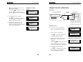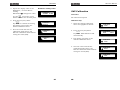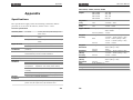
1
Programmable Power Supply
PSH series
USER MANUAL
GW INSTEK PART NO. XXXX-XXXXXX
This manual contains proprietary information, which is protected
by copyrights. All rights are reserved. No part of this manual may
be photocopied, reproduced or translated to another language
without prior written consent of Good Will company.
The information in this manual was correct at the time of printing.
However, Good Will continues to improve products and reserves
the rights to change specification, equipment, and maintenance
procedures at any time without notice.
Good Will Instrument Co., Ltd.
No. 7-1, Jhongsing Rd., Tucheng City, Taipei County 236, Taiwan.
ISO-9001 CERTIFIED MANUFACTURER
Table of Contents
PSH User Manual
Buzzer sound Setting ................................51
Table of Contents
Remote Operation .........................................52
Safety Instructions ........................................ 5
Interface Selection....................................53
Command Syntax .....................................57
Command Set ..........................................58
Safety Symbols ......................................... 6
Safety Guidelines....................................... 6
Power cord for the United Kingdom .............. 9
Calibration ....................................................61
PSH Overview .............................................. 11
Main Features ..........................................12
PSH Series Lineup.....................................13
Package Contents .....................................14
Front Panel ..............................................16
Rear Panel ...............................................18
Display....................................................19
Setup ........................................................... 21
AC Power Cable Assembly ..........................22
Remote Sensing and Local Sensing .............24
Load / Remote Sensing Wire Selection .........25
Load Configuration....................................26
Load Wire Assembly ..................................30
Remote Sensing Wire Assembly ..................32
Functionality Check ...................................34
Rack Mounting (Optional) ..........................40
Calibration Preparation ..............................62
Entering calibration mode ..........................63
Output Voltage calibration..........................64
Output Current calibration .........................66
OVP Calibration ........................................68
FAQ ...............................................................69
Appendix.......................................................71
Specifications ...........................................71
Declaration of Conformity ..........................75
Index ............................................................76
Panel Operation ........................................... 43
Menu Key Overview ..................................44
Constant Voltage/ Constant Current Crossover
Characteristic ...........................................45
Output Voltage Setting ..............................46
Output Current Setting ..............................47
OVP (Output Voltage Protection) Setting ......48
OCP (Output Current Protection) Setting ......49
Display Contrast Setting ............................50
3
4
Safety Instructions
PSH User Manual
Safety Symbols
Safety Instructions
These safety symbols may appear in this manual or on PSH.
This chapter contains important safety
instructions that must be followed when
operating PSH and when keeping it in storage.
Read the following before any operation to
insure safety and to keep the best condition for
PSH.
WARNING
CAUTION
Safety Symbols
Safety Symbols ......................................... 6
Safety
Safety Guidelines....................................... 6
Guidelines
Warning: Identifies conditions or practices that
could result in injury or loss of life.
Caution: Identifies conditions or practices that
could result in damage to PSH or to other
properties.
DANGER High Voltage
Attention Refer to Manual
Power Supply ............................................ 7
Protective Conductor Terminal
Fuse ........................................................ 7
Cleaning PSH ............................................ 7
Earth (ground) Terminal
Operation Environment............................... 8
Storage Environment ................................. 8
Power cord
Power cord for the United Kingdom .............. 9
Safety Guidelines
General
Guideline
CAUTION
•
•
•
•
•
•
Do not place any heavy object on PSH.
Avoid severe impacts or rough handling that
leads to damaging PSH.
Do not discharge static electricity to PSH.
Do not block or obstruct cooling fan vent
opening.
Do not perform measurements at power source
and building installation site (Note below).
Do not disassemble PSH unless you are
qualified as service personnel.
(Note) EN 61010-1:2001 specifies the measurement
categories and their requirements as follows. PSH falls
under category II.
Measurement category IV is for measurement performed
5
6
Safety Instructions
at the source of low-voltage installation.
Measurement category III is for measurement performed
in the building installation.
Measurement category II is for measurement performed
on the circuits directly connected to the low voltage
installation.
Power Supply
WARNING
•
•
PSH User Manual
xylene, and acetone.
Operation
Environment
Relative Humidity: < 85%
Input voltage: 90 ~ 250 V AC, 50/60 Hz
WARNING
The power supply voltage should not fluctuate
more than 10%.
WARNING
Input Breaker Capacity: Over 20A (PSH-10100A,
2050A, 3630A, 6018A)
Connect the protective grounding conductor of
the power cord to earth ground, to avoid
electrical shock.
PSH-1036A
6.3A/250V x2
PSH-2018A
PSH-3610A
PSH-6006A
6.3A/250V x2
PSH-1070A
0.5A/250V x1
PSH-2035A
15A/250V x1
PSH-3620A
PSH-6012A
6.3A/250V x3
PSH-10100A
0.5A/250V x1
PSH-2050A
20A/250V x1
PSH-3630A
PSH-6018A
•
•
•
•
Cleaning PSH
•
•
•
This is a Class A product which may cause radio
interference in a domestic environment. In such
case, take adequate measures.
(Note) EN 61010-1:2001 specifies the pollution degrees
and their requirements as follows. PSH falls under degree
2.
Pollution refers to “addition of foreign matter, solid,
liquid, or gaseous (ionized gases), that may produce a
reduction of dielectric strength or surface resistivity”.
Pollution degree 1: No pollution or only dry,
non-conductive pollution occurs. The pollution has no
influence.
Pollution degree 2: Normally only non-conductive
pollution occurs. Occasionally, however, a temporary
conductivity caused by condensation must be expected.
Pollution degree 3: Conductive pollution occurs, or dry,
non-conductive pollution occurs which becomes
conductive due to condensation which is expected. In
such conditions, equipment is normally protected against
exposure to direct sunlight, precipitation, and full wind
pressure, but neither temperature nor humidity is
controlled.
Make sure the correct type of fuse is installed
before powering up.
Replace the fuse with the specified type and
rating only, for continued fire protection.
Disconnect the power cord before fuse
replacement.
Storage
Environment
Make sure the cause of the fuse blowout is
fixed before fuse replacement.
Altitude: < 2000m
Temperature: 0°C to 40°C
•
Fuse
Location: Indoor, no direct sunlight, dust free,
almost non-conductive pollution (Note below)
Location: Indoor
Relative Humidity: < 70%
Temperature: −10°C to 70°C
Disconnect the power cord before cleaning.
Use a soft cloth dampened in a solution of mild
detergent and water. Do not spray any liquid
into PSH.
Do not use chemicals or cleaners containing
harsh materials such as benzene, toluene,
7
8
Safety Instructions
Power cord for the United Kingdom
When using PSH in the United Kingdom, make sure the power
cord meets the following safety instructions.
NOTE: This lead / appliance must only be wired by competent persons
WARNING: THIS APPLIANCE MUST BE EARTHED
IMPORTANT: The wires in this lead are coloured in accordance with the
following code:
Green/ Yellow: Earth
Blue:
Neutral
Brown:
Live (Phase)
As the colours of the wires in main leads may not correspond with the colours
marking identified in your plug/appliance, proceed as follows:
The wire which is coloured Green & Yellow must be connected to the Earth
terminal marked with the letter E or by the earth symbol or coloured Green
or Green & Yellow.
The wire which is coloured Blue must be connected to the terminal which is
marked with the letter N or coloured Blue or Black.
The wire which is coloured Brown must be connected to the terminal marked
with the letter L or P or coloured Brown or Red.
If in doubt, consult the instructions provided with the equipment or contact
the supplier.
This cable/appliance should be protected by a suitably rated and approved
HBC mains fuse: refer to the rating information on the equipment and/or user
instructions for details. As a guide, cable of 0.75mm2 should be protected by a
3A or 5A fuse. Larger conductors would normally require 13A types,
depending on the connection method used.
Any moulded mains connector that requires removal /replacement must be
destroyed by removal of any fuse & fuse carrier and disposed of immediately,
as a plug with bared wires is hazardous if a engaged in live socket. Any
re-wiring must be carried out in accordance with the information detailed on
this label.
9
PSH Overview
PSH User Manual
PSH Overview
Main Features
PSH Series are modular-type programmable
switching power supplies designed for broad
range of applications. The series consists of 12
models, output ranging from 360W to 1000W.
Switching technology and built-in PFC control
give PSH higher power efficiency, power density,
and power factor compared with other linear
power supplies. Protection mechanisms keep the
output voltage, current, and temperature within
limit. Remote control interface equipped with
SCPI command set and Lab-View Driver
facilitates ATE software development.
Performance
High power factor with PFC control
•
High efficiency power conversion
•
Compact size, light weight
•
Constant voltage operation
•
Constant current operation
•
Output On/Off control
•
Built-in buzzer
•
Self test and calibration
•
LCD display
•
Over voltage protection (OVP)
720W..................................................... 13
•
Over current protection (OCP)
1000/ 1080W .......................................... 13
•
Over temperature protection (OTP)
•
RS-232 (standard) / GPIB (optional) interface
•
IEEE 488.2/SCPI compatible command set
•
LabView driver
•
GPIB remote control interface
•
19 inch standard rack mounting
Main features
Main Features ......................................... 12
Series lineup
360W..................................................... 13
contents
Operation
Main unit ................................................ 14
Protection
Interface
AC input cable kit .................................... 14
Output connection kit ............................... 15
Manual ................................................... 15
Panel
descriptions
Display
descriptions
12 models with wide output range: 6~100A,
10~60V, and 360~1000W.
•
This chapter describes PSH series features and
appearances in a nutshell.
Package
•
Optional items
Front Panel ............................................. 16
Rear Panel .............................................. 18
Default display ........................................ 19
Menu mode display .................................. 20
11
12
PSH Overview
PSH User Manual
PSH Series Lineup
Package Contents
PSH series consist of the following 12 models with various output
voltage and current ratings. For the detailed specifications, see
page71.
Check the contents before using PSH series. Contact your local
dealer in case there is a missing item.
Main unit
360W
PSH-1036A
(Mainframe
10V, 36A
only)
PSH-2018A
20V, 18A
PSH-3610A
36V, 10A
PSH-6006A
60V, 6A
720W
PSH-1070A
(Mainframe +
10V, 70A
one slave
module)
AC input cable
•
Cable gland
•
Terminal cover
•
AC power input cord
kit
PSH-2035A
20V, 35A
PSH-3620A
36V, 20A
PSH-6012A
60V, 12A
1000/ 1080W
PSH-10100A
(Mainframe +
10V, 100A
two slave
modules)
PSH-2050A
20V, 50A
PSH-3630A
36V, 30A
PSH-6018A
60V, 18A
13
14
PSH Overview
Package Contents (cont.)
Output
•
Terminal cover
•
Output cable screw
•
User manual (this document)
•
Programming manual
PSH User Manual
Front Panel
connection kit
Manual
1
LCD Display
2
Power
Shows the output and the configuration status.
See page19 for details.
On
Off
Switch
3
Wheel knob
Sets parameters. Turn right: increase, turn left:
decrease.
4
Output
Turns the output On or Off. When On, the “OUT”
sign appears on the display.
Switch
Out On
CV
15
16
Out Off
2.58V
OCP OUT
2.01A
SET 2.58V
OCP
2.01A
PSH Overview
5
Vset/ Iset/
Enter key
OCP
2.01A
SET 2.58V
6
Iset (edit Current)
SET 2.58V
OCP
2.01A
Switches the editing location and resolution:
Coarse) key before (coarse) or after (fine) the decimal point.
F/C (Fine/
Fine (after decimal)
OCP
2.01A
SET 2.58V
7
Rear Panel
Switches between voltage setting mode and
current setting mode, or confirm the entered
value in the menu mode (see page44).
Vset (edit Voltage)
PSH User Manual
Menu key
SET 2.58V
OCP
2.01A
Enters into the menu mode. For details, see
page44.
Default mode
CV
Coarse (before decimal)
OCP OUT
2.58V
2.01A
1
Menu mode (OVP setting)
2
Set OVP
* 21.10V
Local key
Switches from remote control mode to local
operation mode (page56), OR releases OVP/OCP
error messages and go back to normal operation
(page37), OR enters the calibration mode when
pressed for more than 5 seconds (page61).
Error message example
OCP Error! Press
“Local” to reset
Output
Terminal
3
8
Ground
Terminal
4
Connect the feedback line to compensate for
cable loss. For details, see page24 (theory),
page32 (cable connection).
RS232/ GPIB
Connect the remote control line. For remote
control details, see page52. GPIB requires an
optional module. For installation details, see
the service manual.
Note: Only one interface module (RS232 or
GPIB) can be installed at a time.
Terminal
5
AC input
Terminal
17
18
Connect DUT (Device Under Test). For details,
see page24.
Sense Terminal
Calibration mode
Calibration
Voltage
Connect the output line shield (page25) and
the remote sensing line shield (page32).
Connect the AC power input cable. For
details, see page22.
PSH Overview
Display (cont.)
Display
Default
PSH User Manual
Editing mode
Display mode
display
A
B
C
D
RMT ADRS OCP OUT
CV 10.10V
36.10A
E
A
F
G
A
B
SET 10.10V
E
C
F
MENU
(Default display)
G
CV
RMT: remote control mode
(Nothing): panel operation mode
Not available in editing mode
C
OCP: Output Current Protection On
(Nothing): Output Current Protection Off
D
OUT: Output On
(Nothing): Output Off
Not available in editing mode
G
. To move to the next configuration,
Menu key
press the Menu key repeatedly. When inactive for
more than 5 seconds, the display goes back to the
default mode.
OCP
36.10A
ADRS: RS-232 or GPIB address (available
in remote control)
Not available in editing mode
F
The following displays appear when pressing the
display
D
B
E
Menu mode
CV/CC: Current and Voltage display
mode (Constant Voltage/ Constant
Current)
SET: Current and Voltage editing mode
OCP OUT
2.01A
Set OVP
21.10V
Output Voltage
Protection setting.
For details, see
page48.
Set OCP
ON (OFF)
Output Current
Protection setting.
For details, see
page49.
Set Contrast
70%
Display contrast
setting. For details,
see page50.
Set Buzzer
ON (OFF)
Output Voltage readback value (display
mode)
Output Voltage setting value (editing
mode)
Interface RS232
Baud Rate 9600
Output Current readback value (display
mode)
Output Current setting value (editing
mode)
19
2.58V
20
Buzzer setting. For
details, see page51.
Remote control
interface setting. For
details, see page52.
Setup
AC power cable
assembly
Load
configuration
PSH User Manual
Setup
AC Power Cable Assembly
This chapter describes load configurations and
setup procedures. Follow these instructions to
properly install PSH series.
1 Cable gland +
Terminal Cover
Put the power cable through the cable gland and
the terminal cover, screw them together.
AC Power Cable Assembly ......................... 22
AC power cable requirement ..................... 23
Remote Sensing and Local Sensing ............ 24
Load / Remote Sensing Wire Selection ........ 25
Single Load + Local Sensing...................... 26
Single Load + Remote Sensing .................. 26
Multiple Loads + Local Sensing .................. 27
Multiple Loads + Remote Sensing .............. 27
2 Cable wire +
Terminal
Screw the wire onto the AC input terminal. Note
the wire color: Neutral (white), GND (green), and
Line (black).
CAUTION
Series Operation + Local Sensing............... 28
Series Operation + Remote Sensing ........... 29
Wire assembly
Load Wire Assembly ................................. 30
Remote Sensing Wire Assembly ................. 32
Functionality
Check
Preparation ............................................. 34
Output Voltage & OVP Check ..................... 35
3 Terminal
Output Current Check .............................. 37
Terminal
cover +
OCP Check.............................................. 38
Rack mounting
(optional)
Rack mounting kit contents ....................... 40
Rack mounting assembly .......................... 41
21
22
Screw the terminal cover onto the terminal.
Setup
AC power cable requirement
PSH User Manual
Remote Sensing and Local Sensing
Here is the AC power cable specification, in case of using cables
other than the attached one.
Cable length
≤ 3m
Remote sensing compensates the cable loss between PSH and load,
up to 0.5V. Use remote sensing whenever the load voltage has to
be accurate.
Cable gland
KSS or PG-2013
Local Sensing
VSET
VOUT
(default)
Cable type
(recommended)
Model: SJT
Type: 3 x 14 AWG stranded copper
Rating: 60°C min, 300V
Diameter: 9.143~10.03 mm
VSET = VOUT
VOUT > VLOAD
Model: H05 VV-F
Type: 3G 1.5mm2 stranded copper
Rating: 300V/500V
Diameter: 8.5 ± 0.2 mm
VLOAD
PSH
Load
Output
Setting
VOUT
|VSET–VOUT|
Sense
The sense terminal is internally connected to the
PSH output terminal. The delta between the
voltage setting level (VSET) and the actual output
level (VOUT) is compensated. The load terminal
voltage (VLOAD) might become lower than the
output due to cable loss.
Remote
Sensing
VSET = VLOAD
VOUT > VSET
VSET
VLOAD
VOUT
PSH
Load
Output
Setting
VLOAD
|VSET–VLOAD|
Sense
The sense terminal is connected to the load input
terminal. The delta between the voltage setting
level (VSET) and the actual load voltage (VLOAD) is
compensated. The output voltage (VOUT) might
become higher than the setting due to the
compensation.
23
24
Setup
PSH User Manual
Load / Remote Sensing Wire Selection
Load Configuration
The following instructions apply to both load wire and remote
sensing wire, unless noted.
Select the appropriate configuration for the target application.
For local sensing and remote sensing explanation, see the
previous page.
For connection guideline, see page25 (wire selection), page30 (load
connection), page32 (remote sensing connection).
Wire size (FOR
LOAD ONLY)
Load wires must have enough current capacity
to minimize cable loss and load line impedance.
Voltage drop across a wire should not excess
0.5V. The following list is the wire current rating
at 450A/cm2.
Wire size
(AWG)
20
18
16
14
12
10
8
Wire length
Wire shielding
Max.
current (A)
2.5
4
6
10
16
21
36
Wire size
(AWG)
6
4
2
1
1/0
2/0
Max.
current (A)
Single PSH + single load
Single Load +
Local Sensing
61
97
155
192
247
303
—OUT
—IN
Load
PSH
+OUT
+IN
—Sense
+Sense
Connect the output wire to the load and the sense
terminal to the PSH local output monitor.
To avoid excessive cable loss, shorten the
distance between PSH and load as much as
possible. Remote sensing compensates cable
loss up to 0.5V.
Single Load +
Remote
Sensing
To minimize noise effect and load line
impedance, use shielded pair wiring. Twisted
wires are more effective, especially for remote
sensing.
—OUT
—IN
Load
PSH
+OUT
+IN
—Sense
+Sense
Connect both the output wire and the remote
sensing wire to the load.
Wire shield should be connected to the rear
panel ground connector.
25
26
Setup
Single PSH + multiple Load
Condition
•
•
Sensing
Multiple PSH + single load (series operation)
Output current for each load follows the load
requirement.
Condition
When the sum of the load current surpasses the
rating, PSH automatically switches to CC
(Constant Current) mode.
Multiple Loads
+ Local
PSH User Manual
—OUT
Load #1
+OUT
+IN
—Sense
+Sense
—IN
Up to four PSH series (with identical output
ratings) can be cascaded.
•
Output voltage is the sum of the cascaded PSH.
•
Output current is the same as a single PSH.
Series
—IN
PSH
•
Operation +
—OUT
Local Sensing
Sensing
—OUT
Distribution
Point
Load #2
PSH #2
—OUT
+OUT
—Sense
+Sense
—IN
Load #1
PSH
+OUT
—Sense
+Sense
+IN
—Sense
+Sense
All loads share one PSH output.
+ Remote
Load
+OUT
+IN
Multiple Loads
—IN
PSH #1
First PSH:
Negative output → Negative load input
Positive output → The next PSH negative output
+IN
—IN
Load #2
Intermediate PSH:
Negative output → The previous PSH positive
output
Positive output → The next PSH negative output
+IN
Create a distribution point between PSH and the
loads. PSH compensates the cable loss up to the
distribution point.
To maximize compensation, make sure the
distribution point is closer to the load side.
27
Last PSH:
Negative output → The previous PSH positive
output
Positive output → Positive load input
28
Setup
Series Operation (cont.)
Load Wire Assembly
Series
Operation +
Remote
—OUT
PSH #1
1. Wire
—IN
selection
Load
+OUT
+IN
Sensing
2. Terminal
—Sense
+Sense
PSH #2
PSH User Manual
screw
Select the appropriate wire according to the
guideline on page25.
Replace the two screws on the output terminal
with the hex screw in the output connection kit.
replacement
—OUT
+OUT
—Sense
+Sense
First PSH:
Negative output → Negative load input
Positive output → The next PSH negative output
Negative sense → Negative load input
Positive sense → Positive output monitor
3. Terminal
connection
Intermediate PSH:
Negative output → The previous PSH positive
output
Positive output → The next PSH negative output
Negative sense → The previous PSH positive
output
Positive sense → Positive output monitor
Last PSH:
Negative output → The previous PSH positive
output
Positive output → Positive load input
Negative sense → The previous PSH positive
output
Positive sense → Positive load input
29
30
Screw load wires to the terminal.
Setup
Load Wire Assembly (cont.)
4. Terminal
cover assembly
5. Wire shield
connection
PSH User Manual
Remote Sensing Wire Assembly
Screw the output terminal cover to the rear
panel.
Select the appropriate wire according to the guideline on page25.
Local sensing
The sense terminal is connected to the output
monitor terminal with bare wires.
Remote Sensing
1. Take off the wire jumpers.
Connect the load wire shield to the rear panel
ground connector.
(recommended)
2. Screw wires to the sense (S) side.
•
CAUTION
•
31
32
Do not screw remote sensing wires to the
monitor (M) side.
M+, M− are for output monitoring only. NEVER
screw load wires to the remote sensing
terminal.
Setup
Remote Sensing Wire Assembly (cont.)
5. Wire shield
connection
PSH User Manual
Functionality Check
To minimize noise effect, we recommend
covering the remote sensing wire with ground
shield and connect it to the ground terminal.
Check the PSH basic functionalities before operation.
Preparation
Check items
CAUTION
An open remote sense circuit leads to output
level overshoot. Make sure the line is securely
connected.
Equipment
•
Output Voltage
•
OVP functionality
•
Output Current
•
OCP functionality
Digital
Multimeter
•
•
Current Shunt
PSH – Current
Shunt cable
Multimeter –
Current Shunt
cable
When there is a
problem…
33
34
DC Voltage Accuracy: <±0.1%
Recommended model:
GDM-8245, GDM-8246
•
Current range: >100A
•
Accuracy: <±0.1%
•
Voltage rating: >70V
•
Current rating: >100A
•
N/A
Run calibrations (page61). If this does not solve
the issue, refer to the service center.
PSH User Manual
Setup
4. Make sure the Multimeter shows no value (No output).
Output Voltage & OVP Check
5. Press the Output key
Connection
—
and turn On the output.
The display changes into CV
(Constant Voltage) mode and
shows the OUT sign on the top
right corner.
PSH Series
Digital Multimeter
OUTPUT
+
CV
20.00V
OUT
18.00A
6. Make sure the Multimeter reading and the PSH display show
approximately the same Voltage.
V
7. Increase the PSH output voltage beyond the OVP value.
A
8. Make sure the display shows an error message.
LOCAL
Press the Local key
to get
back to the normal display.
OVP Error! Press
“Local” to reset
Checking step
9. Make sure the output is now turned Off in the display and the
Multimeter shows no value (No output).
1. Power On PSH and connect the Multimeter Voltage
measurement terminal.
2. Set Output Voltage and Output Current to the rating value.
VSET/ ISET
•
PSH-2018A (20V, 18A)
Vset/Iset/Enter key ENTER
switches the cursor between
Voltage and Current.
SET 20.00V
18.00A
F/C
•
•
F/C key
switches the cursor
between before and after the
decimal point.
Wheel knob
changes the value.
3. Press the Menu key once and set the OVP value to rating
voltage + 100mV.
Press the Vset/Iset/Enter
VSET/ ISET
key ENTER
setting.
to confirm the OVP
Set OVP
20.10V
35
36
Setup
PSH User Manual
Output Current Check
OCP Check
Connection
Connection
Current
Shunt
Digital Multimeter
—
PSH Series
+
V
Checking step
1. Power On PSH and connect the Multimeter/ Current Shunt
terminal.
1. Power On PSH and connect the Multimeter / Current Shunt
terminal.
2. Set the Output Voltage and Current value to the rating.
VSET/ ISET
•
Vset/Iset/Enter key
switches
the cursor between Voltage and
Current.
ENTER
F/C
F/C key
switches the cursor
before and after the decimal point.
Wheel knob
PSH Series
+
A
Checking step
•
—
V
A
•
Current
Shunt
Digital Multimeter
2. Set the Output Voltage and Current value to the rating.
PSH-2018A (20V, 18A)
VSET/ ISET
•
SET 20.00V
18.00A
SET 20.00V
•
3. Make sure the Multimeter/Current Shunt shows no output.
OUTPUT
18.00A
F/C
changes the value.
4. Press the Output key
PSH-2018A (20V, 18A)
Vset/Iset/Enter key ENTER
switches the cursor between
Voltage and Current.
•
F/C key
switches the cursor
before and after the decimal point.
Wheel knob
changes the value.
3. Press the Menu key twice to view the OCP setting.
and turn On the output.
Turn the wheel knob
OCP setting to ON.
5. Make sure the Multimeter/Current Shunt reading and the
PSH display show approximately the same Current.
to change
Set OCP
ON
VSET/ ISET
Press the Vset/Iset/Enter key
37
38
ENTER
to confirm the setting.
Setup
The OCP sign appears on the
upper side of the display.
CV
4. Press the Output key
OUTPUT
20.00V
OCP
18.00A
Rack Mounting (Optional)
PSH can be mounted on standard 19 inch rack using GRA-403
rack mounting kit.
and turn On the output.
Rack mounting kit contents
5. Make sure the display shows the error message.
LOCAL
to get
Press the Local key
back to the normal display.
PSH User Manual
OCP Error! Press
“Local” to reset
Main bracket x 1
Front panel x 1
Large decoration board x 1
Medium decoration board x 2
Small decoration board x 2
Binding plate x 6
Handle x 2
Screw M4 * 0.7 L=10mm x 4
6. Make sure the output is now turned Off in the display and the
Multimeter / Current Shunt shows no value (No output).
Screw M3 * 0.5 L = 8mm x 18
39
40
Setup
PSH User Manual
Rack mounting assembly
1. Rack
Confirm the rack mount layout. Make sure there
mounting layout
is a space between each PSH. Below is the
example of rack mounting layout.
2. Decoration
board assembly
3. Binding plate
assembly
4. Main bracket
assembly
Fix the PSH to the main bracket using M3
screws.
Fix the front panel and the handle to the main
bracket using M4 screws.
Once the layout is fixed, screw the decoration
boards to the front panel using M3 screws.
Take off two M3 screws from PSH side panels,
front and rear. Hold the binding plate between
PSH and drive the same screws in.
41
42
Panel Operation
Menu key
PSH User Manual
Panel Operation
Menu Key Overview
This chapter describes the manual operations
done at the front panel, together with the
constant voltage/ constant current crossover
characteristics.
Press the Menu key
Menu key repeatedly.
MENU
. To move to the next item, press the
Default display
Menu Key Overview ................................. 44
CV
2.58V
OCP OUT
2.01A
overview
Output Voltage Protection setting
characteristic
Constant Voltage/ Constant Current Crossover
Characteristic .......................................... 45
Output Voltage
Output Voltage Setting ............................. 46
CV/ CC
Set OVP
* 21.10V
F/C key
setting
Output Current
setting
OVP setting
Set OCP
* ON (OFF)
Output Current Setting ............................. 47
Note ...................................................... 47
Set the OVP value.................................... 48
Set Contrast
* 70%
Clear OVP error ....................................... 48
OCP setting
Turn the OCP On/Off ................................ 49
Clear OCP error ....................................... 49
Display contrast
Set Buzzer
* ON (OFF)
Display Contrast Setting ........................... 50
setting
Buzzer sound
setting
To set the value, use the wheel
knob .
To select the editing point (before or
after the decimal point), press the
Buzzer sound Setting ............................... 51
Interface RS232
Baud Rate 9600
Buzzer condition ...................................... 51
43
44
F/C
repeatedly.
Output Current Protection setting
To enable or disable OCP, use the
wheel knob . When enabled,
“OCP” appears on the default
display.
Display contrast setting
To set the display contrast, use the
wheel knob .
Turn right: increases contrast
Turn left: decreases contrast
Buzzer setting
To enable or disable buzzer sound,
use the wheel knob. The buzzer
sounds when trying to set a value
beyond the specification.
Remote control interface setting
RS232 (standard): To set the baud
rate, use the wheel knob .
GPIB (optional): To set the GPIB
address, use the wheel knob .
Panel Operation
PSH User Manual
Constant Voltage/ Constant Current
Output Voltage Setting
Crossover Characteristic
Operation
PSH series automatically switch
between constant voltage mode
and constant current mode,
according to the load change.
VSET/ ISET
V
1. Press the Vset/ Iset key
repeatedly to move the underline
to the Voltage side.
VSET
When the load current is
smaller than the limit (ISET),
PSH operates in Constant
Voltage mode, changing the
current level according to the
load but keeping the Voltage
level at the limit (VSET).
Constant
Voltage
Constant
Current
I
ISET
3. Use the wheel knob
2.58V
OCP OUT
1.99A
1.33V
10mV (rating voltage < 36V)
20mV (rating voltage ≥ 36V)
OUT
2.00A
45
to change the output voltage.
Step
Constant Current
CC
OCP
2.01A
0.00V ~ rating voltage
The display indicates CV (Constant Voltage) or CC
(Constant Current) on the left side.
CV
SET 2.58V
Range
Let’s take recharging a 12V battery as an example. PSH output
setting is 13.8V, 1A. An empty battery puts a heavy current load
on the power supply. PSH starts running at Constant Current
mode, supplying full 1A current but keeping the voltage lower
than 13.8V. As the battery becomes charged, the load also
becomes smaller. PSH then switches to Constant Voltage mode,
supplying less than 1A current but supplying full 13.8V.
Constant Voltage
OCP
2.01A
F/C
2. Press the F/C key
to move the
underline before or after the
decimal point.
When the load current is the
VSET = Output Voltage setting
same as the limit (ISET), PSH
ISET = Output Current setting
operates in Constant Current
mode, changing the Voltage level
according to the load but
keeping the Current level at the
limit (ISET).
Display
SET 2.58V
46
Panel Operation
PSH User Manual
Output Current Setting
OVP (Output Voltage Protection) Setting
Operation
Set the OVP value
VSET/ ISET
1. Press the Vset/ Iset key
repeatedly to move the underline
to the Current side.
MENU
1. Press the Menu key
repeatedly until the OVP menu
appears.
OCP
SET 2.58V
2.01A
F/C
2. Press the F/C key
to move the
underline before or after the
decimal point.
3. Use the wheel knob
SET 2.58V
CV
2.58V
OCP OUT
2.01A
Set OVP
* 21.10V
OCP
2.01A
F/C
to change the output current.
Range
0.00A ~ rating current
to move the
2. Press the F/C key
underline before or after the
decimal point.
Step
10mA
3. Use the wheel knob
Note
When the output current exceeds the setting
value, PSH automatically switches from CV
(Constant Voltage) to CC (Constant Current)
mode.
Set OVP
* 21.10V
to change the value.
VSET/ ISET
4. Press the Iset/Vset/Enter key
ENTER
to confirm the value.
Clear OVP error
1. When the output voltage exceeds
OVP value, the output is shut off
and an OVP error message
appears on the display.
OVP Error! Press
“Local” to reset
LOCAL
to clear
2. Press the Local key
the error message (the output is
still Off).
47
Range
0.00V ~ rating voltage
Step
10mV (rating voltage < 36V)
20mV (rating voltage ≥ 36V)
48
Panel Operation
PSH User Manual
OCP (Output Current Protection) Setting
Display Contrast Setting
Turn the OCP On/Off
Operation
MENU
1. Press the Menu key
repeatedly until the OCP menu
appears.
MENU
CV
1. Press the Menu key
repeatedly until the Contrast
menu appears.
OCP OUT
2.58V
2.01A
Set OCP
OFF
to change
2. Use the wheel knob
the status to ON (or OFF).
ENTER
Range
5% ~ 95%
to confirm the setting.
Step
6%
OCP Error! Press
“Local” to reset
LOCAL
2. Press the Local key
to clear
the error message (the output is
still Off).
Range
OCP OUT
2.01A
to change the contrast. Clockwise:
2. Use the wheel knob
increase, Counterclockwise: decrease.
Set OCP
ON
Clear OCP error
1. When the output current exceeds
the current setting, the output is
shut off and an OCP error message
appears on the display.
2.58V
Set Contrast
71%
VSET/ ISET
3. Press the Iset/Vset/Enter key
CV
According to the output current
49
50
Panel Operation
PSH User Manual
Buzzer sound Setting
Remote Operation
Operation
This chapter describes the IEEE 488.2 based
remote control configuration, command syntax,
and command set overview. For further
descriptions and examples, refer to the
programming manual.
MENU
1. Press the Menu key
repeatedly until the Buzzer menu
appears.
CV
2.58V
OCP OUT
2.01A
Interface
configuration
Set Buzzer
OFF
RS232 (Standard).................................... 53
GPIB (Optional) ....................................... 55
Interface functionality check ..................... 56
to change
2. Use the wheel knob
the buzzer setting to ON (or OFF).
Command set
Set Buzzer
ON
General commands .................................. 58
3. Press the Iset/Vset/Enter key to
confirm the value.
Buzzer
condition
Command Syntax .................................... 57
Status commands .................................... 59
Miscellaneous commands .......................... 60
When “Set Buzzer ON”, the buzzer sounds under
the following conditions.
* When pressing the panel keys
* When the value setting exceeds the limit
51
52
Remote Operation
PSH User Manual
PC RS-232 pin
Interface Selection
assignment
6789
RS232 (Standard)
PSH – PC
Baud rate
setting
MENU
1. Press the Menu key
repeatedly until the
Interface menu appears.
CV
2.58V
connection
OCP OUT
2.01A
2. Use the wheel knob
rate.
to select the baud
VSET/ ISET
3. Press the Iset/Vset/Enter key
confirm the setting.
ENTER
to
4. Connect the RS232 cable between your PC
and PSH rear panel. PSH switches to remote
control mode as soon as the connection is
established.
interface
protocol
PSH RS-232 pin
Baud rate: 9600, 4800, 2400, 1200 (selectable)
Parity: None (fixed)
Stop bit: 1 (fixed)
Data bit: 8 (fixed)
12345
assignment
6789
Pin 2: RxD
Pin 3: TxD
Pin 5: GND
Pin 1, 4, 6 ~ 9: No Connection
53
54
Pin 2: TxD
Pin 3: RxD
Pin 5: GND
Pin 1, 4, 6 ~ 9: No Connection
Null-modem connection, in which transmit (TxD)
and receive (RxD) lines are crosslinked, is
required.
PSH
Interface RS232
Baud Rate 9600
RS-232
12345
PC
Pin2 RxD
TxD Pin2
Pin3 TxD
RxD Pin3
Pin5 GND
GND Pin5
Remote Operation
GPIB (Optional)
Interface functionality check
Refer to the service manual for GPIB module installation.
Note: The RS232 module has to be replaced with the GPIB
module: they cannot be used together.
Address setting
PSH User Manual
Remote mode
display
MENU
1. Press the Menu key
repeatedly until the
Interface menu appears.
CV
2.58V
RMT
OCP
CV 0.05V
1.05A
To enable panel operation, press the Local
OCP OUT
2.01A
LOCAL
key
control.
Functionality
Interface GPIB
Address 8
check
GW.Inc,PSH-2018A,12345678,FW1.00
ENTER
to
4. Connect the GPIB cable between your PC and
PSH rear panel. PSH switches to remote
control mode as soon as the connection is
established.
constraints
•
•
Run this query command via the terminal.
This should return the Manufacturer, Model
number, Serial number, and Firmware version in
the following format.
VSET/ ISET
3. Press the Iset/Vset/Enter key
confirm the setting.
. This also disconnects the remote
*idn?
to select the address.
2. Use the wheel knob
GPIB address: 1 ~ 30
GPIB
In the remote control mode, the display shows
“RMT” on the top left corner. The panel operation
is disabled.
Address range: 1 ~ 30
Altogether less than 15 devices, less than 20m
total cable length, maximum 2m between each
device
•
Unique address assigned for each device
•
At least 2/3 of the GPIB devices turned On
•
No loop or parallel structure
55
56
Remote Operation
PSH User Manual
Command Syntax
Command Set
The commands are fully compatible with IEEE488.2 (1992)
standard and partially compatible with SCPI (1994) standard.
Commands are non-case sensitive.
For more detailed information, refer to the Programming Manual
which is downloadable from www.gwinstek.com.tw.
Example
command
:chan1:prot:curr <0/1> LF
1
1:
2:
3:
4:
2
3
General commands
4
:chan1:curr?
Command Header
Single space
Parameter
Message Terminator OR Message Separator
Header
Several command header elements (nodes) can be
concatenated to form a complex command.
The above example can be separated into:
:chan1: (root node) + prot: + curr:
Parameter
<0/1>
0 or 1.
<1~4>
Integer between 1, 2, 3, or 4.
<0.01~5>
Decimal number between 0.01 and 5.
Command
example
Message
Terminator
Message
Marks the end of a command line. Any of the
following is acceptable, in accordance with
IEEE488.2 standard.
LF^END
Line feed code (hexadecimal 0A)
with END message
LF
Line feed code
<dab>^END
Last data byte with END message
Returns the output current (unit: A).
Range: 0.01~rating current
:chan1:curr
Sets the output current (unit: A).
<0.01~rating>
Range: 0.01~rating current
:chan1:volt?
Returns the output voltage (unit: V).
Range: 0.01~rating voltage
:chan1:volt
Returns the output voltage (unit: V).
<0.01~rating>
Range: 0.01~rating current
:chan1:meas:cu Returns the actual output load current (unit: A).
rr?
:chan1:meas:vo Returns the actual output load voltage (unit: V).
lt?
:chan1:prot:cur Returns the Over Current Protection status.
r?
Range: 0 (Off), 1 (On)
:chan1:prot:cur Sets the Over Current Protection.
r <0/1>
Range: 0 (Off), 1 (On)
:chan1:prot:volt Returns the Over Voltage Protection value.
?
Range: 0.01~rating (unit: V)
:chan1:prot:volt Sets the Over Voltage Protection value.
<0.01~rating>
Range: 0.01~rating (unit: V)
:chan1:prot:cle Clears the OCP & OVP protection message from
the display.
:outp:stat?
Returns the output status.
Range: 0 (Output Off), 1 (Output On)
:outp:stat
Sets the output status.
<0/1>
Range: 0 (Output Off), 1 (Output On)
; (semicolon) Command separator.
Separator
57
58
Remote Operation
PSH User Manual
Status commands
Miscellaneous commands
*cls
*idn?
*ese?
*ese <0~255>
*esr?
*sre?
*sre <0~255>
*stb?
:stat:oper:cond?
:stat:oper:enab?
:stat:oper:enab
<0~32767>
:stat:oper:even?
:stat:pres
:stat:ques:enab
?
:stat:ques:enab
<0~32767>
:stat:oper:even?
Clears all event status registers (Output Queue,
Operation Event Status, Questionable Event
Status, Standard Event Status)
Returns the ESER (Event Status Enable
Register) contents.
Example: 130→means ESER=10000010
Sets the ESER contents.
Example: *ese 65→sets ESER to 01000001
Returns and clears the SESR (Standard Event
Status Register) contents.
Example: 198→means SESR=11000110
Returns the SRER (Service Request Enable
Register) contents.
Example: 3→means SRER=00000011
Sets the SRER contents.
Example: *SRE 7→SRER=00000111
Returns the SBR (Status Byte Register) contents.
Example: 81→means SBR=01010001
Returns the Operation register contents.
Returns the mask conditions of the event
register. Range: 0~32767
Example: 32767 means all 15bits are set to 1.
Returns the mask conditions of the event
register. Range: 0~32767
Example: 32767 sets all 15bits to 1.
Returns the operation register contents.
Example: 32767 means all 15bits are set to 1.
Sets the operation register and questionable
enable register to zero.
Returns the mask conditions of the event
register. Range: 0~32767
Example: 32767 means all 15bits are set to 1.
Returns the mask conditions of the event
register. Range: 0~32767
Example: 32767 sets all 15bits to 1.
Returns the questionable register contents.
Example: 32767 means all 15bits are set to 1.
59
*opc?
*opc
*rcl <1~99>
*rst
*sav <1~99>
*tst?
*wai
:syst:err?
:syst:vers?
60
Returns the power supply ID as Manufacturer,
Model No, Serial No, Firmware version.
Example: GW.Inc,PSH-2018A,12345678,FW1.00
“1” is placed in the output queue when all the
pending operations are completed.
Sets the operation complete bit (bit0) in SERS
(Standard Event Status Register) when all the
pending operations are completed.
Recalls the panel setup from internal memory.
Example: *RCL 1→recalls setup from memory1
Recalls the default panel setup (reset the device).
Saves the panel setup to internal memory.
Example: *SAV 1→saves setup to memory1
Run the self-test for RAM and ROM and returns
0 (successful) or -300 (unsuccessful).
Prevents execution of further commands until all
the pending operations are completed.
Returns the error number followed by the error
message from the queue.
Example: 0, “No error”
Returns the SCPI version.
Example: 1994.0
Calibration
Setup
PSH User Manual
Calibration
Calibration Preparation
Run calibration when the output exceeds the
specification, or when the functionality check
(page34) fails. To get the optimal result, make
sure PSH is powered for at least 30 minutes
before the calibration.
Calibration
condition
Calibration Preparation ............................. 62
Calibration
items
Entering calibration mode ......................... 63
Calibration
Output Voltage calibration......................... 64
Output Current calibration......................... 66
Calibration
Equipment
•
At least 30 minutes of warm-up time
•
Temperature: 23 ± 5 °C
•
Relative Humidity: ≤ 80%
•
Minimum/ Maximum Output Voltage
•
Minimum/ Maximum Output Current
•
OVP functionality
Digital
Multimeter
•
•
OVP Calibration ....................................... 68
Current Shunt
PSH – Current
Shunt cable
Multimeter –
Current Shunt
cable
61
62
DC Voltage Accuracy: <±0.1%
Recommended model:
GDM-8245, GDM-8246
•
Current range: >100A
•
Accuracy: <±0.1%
•
Voltage rating: >70V
•
Current rating: >100A
•
N/A
Calibration
Entering calibration mode
1. Press the Local key for 5 seconds.
The password entry menu
appears.
2. Enter the model number as the
password.
Wheel knob
changes the digit.
PSH User Manual
Output Voltage calibration
Connection
Please enter the
Password: 0
PSH Series
Digital Multimeter
—
+
(PSH-2018A)
F/C
moves the cursor to
F/C key
the next digit.
V
Please enter the
Password: 2018
A
VSET/ ISET
3. Press the Vset/Iset/Enter key
ENTER
as confirmation.
4. The calibration menu appears.
Wheel knob
selects the item.
Calibration step
VSET/ ISET
Vset/Iset/Enter key
•
ENTER
confirms the selection.
Minimum/Maximum output
voltage calibration
1. Enter the Voltage calibration
menu. See page63 for details.
Calibration
Voltage
2. Press the Vset/Iset/Enter
VSET/ ISET
•
•
Minimum/Maximum output
current calibration
Over Voltage Protection calibration
Calibration
Current
key ENTER and enter Minimum
Voltage calibration mode.
Calibration
OVP
3. Adjust the display value to the
Multimeter reading.
Wheel knob
changes the value.
F/C
•
Save the calibration result and exit
the calibration menu
F/C key
moves the cursor
before and after the decimal point.
Calibration
Save
Exit calibration menu without
saving the calibration result
Calibration
Voltmin 0.00V
Multimeter reading: 0.02V
Calibration
Voltmin 0.02V
4. Press the Vset/Iset/Enter
VSET/ ISET
•
Calibration
Voltage
key ENTER to confirm the setting.
The display enters Maximum
Voltage calibration mode.
Calibration
Exit
63
64
Calibration
Voltmax 20.00V
Calibration
5. Adjust the display value to the
Multimeter reading.
Wheel knob
changes the value.
F/C
F/C key
moves the cursor
before and after the decimal point.
PSH User Manual
Output Current calibration
Multimeter reading:
20.03V
Connection
Calibration
Voltmax 20.03V
Digital Multimeter
key ENTER to confirm the setting.
The display goes back to the
default calibration menu.
7. Save the result and exit the
calibration mode (Save), OR
Exit the calibration mode without
saving the result (Exit).
—
PSH Series
+
V
6. Press the Vset/Iset/Enter
VSET/ ISET
Current
Shunt
Calibration
Voltage
A
Calibration
Save
Calibration step
Calibration
Exit
1. Enter the Current calibration
menu. See page63 for details.
2. Press the Vset/Iset/Enter
VSET/ ISET
key ENTER and enter Maximum
Current calibration mode.
3. Adjust the display value to the
Multimeter / Current Shunt
reading.
Wheel knob
changes the value.
F/C
Calibration
Current
Calibration
CurrMax 18.00A
Multimeter reading:18.02A
Calibration
CurrMax 18.02A
F/C key
moves the cursor
before and after the decimal point.
4. Press the Vset/Iset/Enter
VSET/ ISET
key ENTER to confirm the setting.
The display enters Minimum
Current calibration mode.
65
66
Calibration
CurrMin 0.00A
Calibration
5. Adjust the display value to the
Multimeter / Current Shunt
reading.
Wheel knob
changes the value.
F/C
Multimeter reading: 0.02A
OVP Calibration
Calibration
CurrMin 0.02A
Connection
F/C key
moves the cursor
before and after the decimal point.
No connection required
Calibration step
6. Press the Vset/Iset/Enter
VSET/ ISET
key ENTER to confirm the setting.
The display goes back to the
default calibration menu.
7. Save the result and exit the
calibration mode (Save), OR
Exit the calibration mode without
saving the result (Exit).
PSH User Manual
Calibration
Current
1. Enter the Voltage calibration
menu. See page63 for details.
Calibration
Save
2. Press the Vset/Iset/Enter
VSET/ ISET
key ENTER . PSH calibrates OVP
automatically.
Calibration
Exit
3. The display goes back to the
default calibration menu.
4. Save the result and exit the
calibration mode (Save), OR
Exit the calibration mode without
saving the result (Exit).
Calibration
OVP
Calibration
100%
OVP
Calibration
OVP
Calibration
Save
Calibration
Exit
67
68
FAQ
FAQ
The OVP value/ OCP status has not been changed.
After editing OVP value and OCP status, press
VSET/ ISET
the Vset/Iset/Enter key ENTER to confirm.
Otherwise the setting does not change.
The front panel does not respond.
When in remote control mode, PSH does not
respond to panel operations. Terminate the
LOCAL
remote operation or press the Local key
on the front panel. The “RMT” message
disappears from the display and panel operation
is resumed.
The actual output is lower than the setting.
The cable loss might be causing the load voltage
lower than the setting. Upgrade the output cable
to a better capacity and/or use the remote sense
to compensate for the voltage drop. See page25
(theory) and page25 (cable assembly).
The actual output is much higher than the setting.
The remote sensing (page24) compensates for
the cable loss for up to 0.5V. If the output level
goes much higher, the remote sensing terminal
might be disconnected. Make sure the
connection is secure. See page32 for details.
The load wire does not fit into the terminal.
Make sure you are NOT connecting the load wire
to the remote sensing terminal. Refer to page30
for connection details.
If there is still a problem, please contact your local dealer or
GWInstek at www.gwinstek.com.tw / [email protected].
69
Appendix
PSH User Manual
PSH-1036A/ 2018A/ 3610A/ 6006A
Appendix
Output
Specifications
The specifications apply under the following conditions: PSH is
powered on for at least 30 minutes, within +20°C~+30°C.
Common specification
Recovery Time
CV mode
10V, 36A
PSH-2018A
20V, 18A
PSH-3610A
36V, 10A
PSH-6006A
60V, 6A
Regulation
Load
≤ 0.1% + 5mV
(C.V.)
Line
≤ 0.05% + 5mV
Regulation
Load
≤ 0.2% + 5mA
(C.C.)
Line
≤ 0.2% + 5mA
Ripple & Noise
Voltage (mVrms)
≤ 10mVrms, 100mVpp,
20Hz~20MHz
≤ 2ms (50% step load change from
25%~75%)
Response Time
PSH-1036A
Voltage Up
≤ 150ms (10%~90% ≤ 95% rating
load)
Voltage Down
Program
≤ 10mVrms,100mVpp,20Hz~20MHz
Current (mArms)
≤ 0.2% + 40mA
Temperature
Voltage
≤ 100ppm/ °C
Coefficient
(25±5°C)
Protection
Over Voltage Protection, Over Current Protection, Over
Output On/Off
Available
AC Power Input
100~230V, 50/ 60 Hz
Operation
Location
Indoor
Condition
Altitude
≤ 2000m
Ambient
Specification: 10°C~35°C (50°F~95°F)
temperature
Operation: 0°C~40°C (32°F~104°F)
Relative
85% RH (maximum), non condensing
Storage
Category II (for details, see page6)
Degree 2 (for details, see page8)
Program
Readback
Voltage & OVP
10mV (rating ≤ 36V)
Current
10mA
Voltage
≤ 0.05% + 25mV (rating ≤ 36V)
≤ 0.05% + 50mV (rating > 36V)
Accuracy
Current
≤ 0.2% + 30mA
Readback
Voltage
10mV (rating ≤ 36V)
Resolution
Current
10mA
Fuse
6.3A/ 250V AC x 2
Dimensions
108 x 141 x 388 mm
Weight
Approx. 3.3kg
(Meter)
−10°C~70°C, 70% RH (maximum)
User manual, Programming manual, Cable gland, AC
power cord, AC input cover, O/P terminal cover
71
≤ 0.2% + 30mA
20mV (rating > 36V)
(Meter)
Condition
Accessories
≤ 0.1% + 50mV (rating ≤ 36V)
≤ 0.1% + 100mV (rating > 36V)
Current
Humidity
Pollution
≤ 0.05% + 50mV (rating > 36V)
Resolution
Heat Protection, Inrush Current Protection
Installation
≤ 0.05% + 25mV (rating ≤ 36V)
OVP
≤ 150ms (90%~10% ≥ 10% rating
Voltage (mVrms)
≤ 0.2%
Voltage
Accuracy
load)
Ripple & Noise
Current (mArms)
72
20mV (rating > 36V)
Appendix
PSH User Manual
PSH-1070A/ 2035A/ 3620A/ 6012A
PSH-10100A/ 2050A/ 3630A/ 6018A
Output
Output
PSH-1070A
10V, 70A
PSH-10100A
10V, 100A
PSH-2035A
20V, 35A
PSH-2050A
20V, 50A
PSH-3620A
36V, 20A
PSH-3630A
36V, 30A
PSH-6012A
60V, 12A
PSH-6018A
60V, 18A
Regulation
Load
≤ 0.1% + 5mV
Regulation
Load
≤ 0.1% + 5mV
(C.V.)
Line
≤ 0.05% + 5mV
(C.V.)
Line
≤ 0.05% + 5mV
Regulation
Load
≤ 0.2% + 10mA
Regulation
Load
≤ 0.2% + 15mA
(C.C.)
Line
≤ 0.2% + 10mA
(C.C.)
Line
≤ 0.2% + 15mA
Ripple & Noise
Voltage (mVrms)
≤ 10mVrms, 100mVpp,
Ripple & Noise
Voltage (mVrms)
≤ 10mVrms, 100mVpp,
20Hz~20MHz
Program
20Hz~20MHz
Current (mArms)
≤ 0.2% + 20mA
Voltage
≤ 0.05% + 25mV (rating ≤ 36V)
Program
≤ 0.05% + 50mV (rating > 36V)
Accuracy
Accuracy
OVP
≤ 0.1% + 50mV (rating ≤ 36V)
Current (mArms)
≤ 0.2% + 40mA
Voltage
≤ 0.05% + 25mV (rating ≤ 36V)
≤ 0.05% + 50mV (rating > 36V)
OVP
≤ 0.1% + 100mV (rating > 36V)
Current
Program
≤ 0.1% + 100mV (rating > 36V)
≤ 0.2% + 60mA (rating ≤ 10V)
Current
≤ 0.2% + 60mA (rating ≤ 20V)
Voltage & OVP
10mV (rating ≤ 36V)
≤ 0.2% + 30mA (rating ≤ 60V)
20mV (rating > 36V)
Program
Current
20mA (rating ≤ 10V)
Resolution
Voltage
(Meter)
Readback
Current
Voltage
(Meter)
Voltage & OVP
10mV (rating ≤ 36V)
20mV (rating > 36V)
Current
10mA (rating ≤ 60V)
Accuracy
≤ 0.2% + 90mA (rating ≤ 10V)
≤ 0.2% + 30mA (rating ≤ 60V)
Resolution
Readback
≤ 0.1% + 50mV (rating ≤ 36V)
30mA (rating ≤ 10V)
≤ 0.05% + 25mV (rating ≤ 36V)
20mA (rating ≤ 20V)
≤ 0.05% + 50mV (rating > 36V)
10mA (rating ≤ 60V)
≤ 0.2% + 60mA (rating ≤ 10V)
Readback
≤ 0.2% + 30Ma (rating ≤ 60V)
(Meter)
10mV (rating ≤ 36V)
Accuracy
Voltage
≤ 0.05% + 25mV (rating ≤ 36V)
≤ 0.05% + 50mV (rating > 36V)
Current
≤ 0.2% + 90mA (rating ≤ 10V)
20mV (rating > 36V)
≤ 0.2% + 60mA (rating ≤ 20V)
20mA (rating ≤ 10V)
≤ 0.2% + 30Ma (rating ≤ 60V)
Resolution
Current
Fuse
6.3A/ 250VAC x 2, 0.5A/ 250VAC x 1, 15A/ 250VAC x 1
(Meter)
Dimensions
188 x 141 x 388 mm
Resolution
Weight
Approx. 6.2kg
Readback
10mA (rating ≤ 60V)
Voltage
10mV (rating ≤ 36V)
20mV (rating > 36V)
Current
30mA (rating ≤ 10V)
20mA (rating ≤ 20V)
10mA (rating ≤ 60V)
73
Fuse
6.3A/ 250VAC x 3, 0.5A/ 250VAC x 1, 20A/ 250VAC x 1
Dimensions
268 x 141 x 388 mm
Weight
Approx. 9.3kg
74
Appendix
PSH User Manual
Declaration of Conformity
Index
We
GOOD WILL INSTRUMENT CO., LTD.
(1) No.7-1, Jhongsing Rd., Tucheng City, Taipei County, Taiwan
(2) No. 69, Lu San Road, Suzhou City (Xin Qu), Jiangsu Sheng, China
declare, that the below mentioned product
Type of Product: Power Supply
Model Number:
PSH-1036A/ 2018A/ 3610A/ 6006A
PSH-1070A/ 2035A/ 3620A/ 6012A
PSH-10100A/ 2050A/ 3630A/ 6018A
are herewith confirmed to comply with the requirements set out in the Council
Directive on the Approximation of the Law of Member States relating to
Electromagnetic Compatibility (89/336/EEC, 92/31/EEC, 93/68/EEC) and Low
Voltage Directive (73/23/EEC, 93/68/EEC).
For the evaluation regarding the Electromagnetic Compatibility and Low Voltage
Directive, the following standards were applied:
◎ EMC
EN 61326-1: Electrical equipment for measurement, control and laboratory use
–– EMC requirements (1997 + A1:1998 + A2:2001 + A3:2003)
Conducted Emission
Electrostatic Discharge
Radiated Emission
EN 61000-4-2: 1995 + A1:1998 + A2:2001
EN 55011: Class A 1998 + A1:1999 +
A2:2002
Current Harmonics
Radiated Immunity
EN 61000-3-2: 2000 + A2:2005
EN 61000-4-3: 2002 + A1:2002
Voltage Fluctuations
Electrical Fast Transients
EN 61000-3-3: 1995 + A1:2001
EN 61000-4-4: 2004
------------------------Surge Immunity
EN 61000-4-5: 1995 + A1:2001
------------------------Conducted Susceptibility
EN 61000-4-6: 1996 + A1:2001
------------------------Power Frequency Magnetic Field
EN 61000-4-8: 1993 + A1:2001
------------------------Voltage Dip/ Interruption
EN 61000-4-11: 2004
◎ Safety
Low Voltage Equipment Directive 73/23/EEC
Safety Requirements
IEC/EN 61010-1: 2001
A
AC input
cable assembly................................... 22
cord requirement............................... 23
terminal ............................................. 18
C
calibration
certificate........................................... 15
CC
characteristic..................................... 45
cleaning PSH ....................................... 5, 7
current
OCP setting ....................................... 49
output setting .................................... 47
CV
characteristic..................................... 45
D
display
contrast setting ................................. 50
default mode...................................... 19
fine/coarse.......................................... 17
menu mode ...................................20, 44
output On/Off .................................... 16
remote control mode.......................... 17
E
EN 55011 ............................................... 75
EN 61000 ............................................... 75
EN 61010 ........................................6, 8, 75
F
faq .......................................................... 69
feature list ............................................. 12
75
76
front panel.............................................. 16
faq ...................................................... 69
functionality check
OCP.................................................... 38
output current ................................... 37
output voltage.................................... 35
OVP.................................................... 35
setup .................................................. 34
fuse
rating ................................. 7, 72, 73, 74
safety instruction................................. 7
G
GPIB
interface setting................................. 55
I
IEEE remote control
general commands............................. 58
miscellaneous commands .................. 60
status commands............................... 59
syntax ................................................ 57
O
OCP
check .................................................. 38
operation environment
safety instruction............................. 5, 8
output
cable assembly................................... 30
cable selection.................................... 25
current check ..................................... 37
current setting................................... 47
faq ...................................................... 69
load configuration.............................. 26
terminal ............................................. 18
Index
voltage check ......................................35
configuration ..................................... 26
voltage setting ..............................43, 46
theory................................................. 24
OVP
check ...................................................35
P
S
safety
guidelines............................................. 6
package contents ....................................14
symbol.................................................. 6
power supply
UK power cord..................................... 9
safety instruction ................................ 7
protection
OCP setting ........................................49
OVP setting ........................................48
PSH lineup .............................................13
R
rack mounting
assembly method................................41
parts list .............................................40
rear panel ...............................................18
remote control
display mode.......................................17
terminal..............................................18
remote sensing
cable assembly....................................32
sound setting ......................................... 51
specification ........................................... 71
storage environment
safety instruction ............................ 5, 8
T
table of contents....................................... 3
V
verification
equipment.......................................... 64
output voltage.................................... 66
setup .................................................. 63
voltage
output setting .................................... 46
OVP setting ....................................... 48
cable selection ....................................25
77