1
इंटरनेट
मानक
Disclosure to Promote the Right To Information
Whereas the Parliament of India has set out to provide a practical regime of right to
information for citizens to secure access to information under the control of public authorities,
in order to promote transparency and accountability in the working of every public authority,
and whereas the attached publication of the Bureau of Indian Standards is of particular interest
to the public, particularly disadvantaged communities and those engaged in the pursuit of
education and knowledge, the attached public safety standard is made available to promote the
timely dissemination of this information in an accurate manner to the public.
“जान1 का अ+धकार, जी1 का अ+धकार”
“प0रा1 को छोड न' 5 तरफ”
“The Right to Information, The Right to Live”
“Step Out From the Old to the New”
Mazdoor Kisan Shakti Sangathan
Jawaharlal Nehru
IS 6756 (2001): Electrical and Electronic Measuring
Equipment - Documentation [LITD 8: Electronic Measuring
Instruments, Systems and Accessories]
“!ान $ एक न' भारत का +नम-ण”
Satyanarayan Gangaram Pitroda
“Invent a New India Using Knowledge”
“!ान एक ऐसा खजाना > जो कभी च0राया नहB जा सकता ह”
है”
ह
Bhartṛhari—Nītiśatakam
“Knowledge is such a treasure which cannot be stolen”
1S 6756:2001
IEC 1187 (1993)
/ndian Standard
ELECTRICAL AND ELECTRONIC MEASURING
EQUIPMENT — DOCUMENTATION
(First Revision )
ICS 17.220.20
@ BIS 2001
BUREAU
MANAK
August2001
OF
BHAVAN,
IN DI AN
STAN
9 BAHADUR
SHAH
NEW DELHI 110002
DARDS
ZAFAR
MARG
Price Group 7
Electronic
Measuring
Instruments,
Systems and Accessories
Sectional Committee,
LTD 21
NATIONAL
FOREWORD
This Indian
measuring
(lEC) was
Measuring
Electronics
Standard (First Revision) which is identical with IEC 1187 (1993) ‘Electrical and electronic
equipment — Documentation’
issued by the International Electrotechnical
Commission
adopted by the Bureau of Indian Standards on the recommendation
of
Electronic
Instruments,
Systems and Accessories
Sectional Committee
and approval
of the
and Telecommunication
Division Council.
This standard applies to the technical documentation
to be supplied with electrical
measuring equipment for use in laboratories and for testing and servicing.
and electronic
This standard was first published in 1972 and was identical to IEC 278 (1968) ‘Electronic measuring
equipment — Documentation’. IEC 278 has been withdrawn and replaced by IEC 1187 (1993). In view
of the technological advances at the international level this Indian Standard is being revised to align it
with the latest international practices.
The text of the IEC has been approved as suitable for publication as Indian Standard without
deviations.
Certain conventions
are, however, not identical to those used in Indian Standards.
Attention is particularly drawn to the following:
a)
Wherever the words ‘International
read as ‘Indian Standard’.
Standard’ appear referring to this standard,
b)
Comma (,) has been used as a decimal marker while in Indian Standards,
is to use a point (.) as the decimal marker.
they should be
.
the current practice
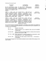
CROSS REFERENCES
In the adopted standard, reference appears to certain International Standards for which Indian
Standards also exist. The corresponding Indian Standards which are to be substituted in their place
are listed below along with their degree of equivalence for the editions indicated:
“
IEC 68 Environmental
Degree of
Equivalence
Corresponding
Indian Standard
International
Standard
testing
IS 9000
Basic environmental
procedures
for
electrical
electronics items
Technically
equivalent
testing
and
IEC 359 (1987) Expression of the
of
electrical
and
performance
electronic measuring equipment
IS 9176:
2001 Expression
of the
performance of electrical and electronic
measuring equipment (under print)
IEC
414
(1973)
Safety
requirements
for indicating
and
measuring
recording
electrical
instruments and their accessories
a)
IS 9249 (Part 1) : 1979
Safety
requirements
for indicating
and
recording
electrical
measuring
instru-ments and their accessories:
Part 1
Common
safety
requirements for instruments
b)
IS 9249 (Part 2) : 1982 Safety
requirements
for indicating
and
recording
electrical
measuring
instru-ments and their accessories:
Part 2 Safety
requirements
for
instruments using a mains supply
Identical
1
Technically
1
(Continued
equivalent
on third cover)
IS 6756:2001
IEC 1187(1993)
Indian Standard
ELECTRICAL AND ELECTRONIC MEASURING
EQUIPMENT — DOCUMENTATION
(First Revision )
1
,1
,.
L’,
Scope and object
{
This standard applies to the technical documentation
electronic measuring equipment for use in laboratories.
to be supplied
with electrical
and
The object of this standard is:
-
to achieve an acceptable
-
to prevent the use of incorrect expressions,
to determine
level of uniformity,
in general terms the basic contents and structure,
of the documentation supplied with the equipment in order to give the user sufficient
information on installation, use, safety, application, technical specification, principle of
operation, testing, servicing and lists of options, accessories and replaceable parts.
NOTE - This documentation may be contained in one manual or in a set of separate manuals covering the
various topics. In the latter case, each volume should contain a list of contents of the other volumes.
2
Normative
references
The following normative documents contain provisions which, through reference in this
text, constitute provisions of this International Standard. At the time of publication, the
editions indicated were valid. All normative documents are subject to revision, and parties
to agreements based on this International Standard are encouraged to investigate the
possibility of applying the most recent editions of the normative documents indicated
below. Members of IEC and ISO maintain registers of currently valid International
Standards.
lEC 68, ErwironrnerW
IEC 113, Diagrams,
IEC 359: 1987,
equipment
testing
charts,
tab/es
Expression
of the performance
IEC 414: 1973, Safety requirements
instruments and their accessories
IEC 417:1973,
Graphical
the single sheets
IEC 617, Graphical
symbok
IEC 801, Electromagnetic
equipmerd
symbols
of electrical
for indicating
and
for use on equipment.
and
electronic
measuring
recording
electrical
measuring
Index, survey
and compilation
of
for diagrams
compatibility
for industrial-process
1
measurement
and
control
‘
.*
IS 6756:2001
IEC 1187(1993)
IEC 950: 1991, Safety
equipment
of information
technology
equipment,
IEC 1010-1: 1990, Safety requirements
for electrical
and laboratory
use - Part 1: General requirements
Amendment
1 (1992)
including
equipment
electrical
for measurement,
business
control,’
CISPR 11: 1990, Limits and methods of measurement
of electromagnetic
disturbance
characteristics
of industrial, scientific and medical (ISM) radio-frequency
equipment
CISPR 14:1985,
Limits and methods of measurement
of radio interference
characteristics
of household electrical appliances, portable tools and similar electrical apparatus
ISO 216: 1975,
A and B series
3
Writing
paper
and certain
classes
of printed
matter
-
Trimmed
sizes
-
Definitions
For the purposes of this International Standard the following definitions apply. Some of
these definitions have been taken from the International
Electrotechnical
Vocabulary
(IEV), from IEC 359, or from other applicable IEC standards.
3.1
address:
operations.
A unique code identifying the equipment when it is used in remote control
3.2
assembly:
A number of basic parts or subassemblies,
joined together to perform a specified function.
3.3
adjustments:
specification.
The
process
of making
the
equipment
or any combination
conform
thereof,
to its technical
3.4
block diagram:
A relatively simple diagram to facilitate understanding
of the
principle of operation. It is a diagram in which the main functional units of the equipment
(or part thereof) together with the mutual relationships between them are represented by
symbols or simple figures without necessarily showing all the connections.
3.5
calibration:
All the operations for the purpose of determining the values of the
errors and, if necessary, other metrological properties of a measuring instrument. After
calibration and possible adjustment, the residual errors can be noted to produce correction
values if required.
3.6
circuit diagram: An explanatory diagram intended to facilitate the understanding
the details of the operation of the equipment. It shows by symbols all the components
the equipment (or part(s) of the equipment) and all their interconnections,
particularly
the electrical connections.
of
of
all
IS 6756:2001
IEC 1187 (1993)
3.7
communication
protocol: A formal statement of the procedures (a set of rules)
that are adopted by the interconnected
equipment to ensure an orderly and correct
transfer of information between the devices.
3.8
component
location iiiustration:
A diagram or photograph in which the eiements
are displayed in a possibly simplified, but weli recognizable form, showing their piaces in
the equipment or subassemblies.
3.9
correction
tabie or graph: Tabie or graph containing data which provide for
corrections on equipment dispiays, taking into account errors found during calibration, but
which shail be disregarded when assigning a ciass index (accuracy) to the equipment.
3.10
data bus (instrumentation bus): A set of signai iines used by an interface system
to which a number of instruments or parts of an instrument are connectable and over
which messages can be carried.
3.11
preset vaiue (defauit):
The initial settings
exampie, after a ‘power-on” or a generai clear action.
of the
equipment
or function,
3.12
device dependent
codes: The set of males, specific to a given
intended for sending and receiving messages to and from the outside worid.
for
equipment,
3.13
error codes: Codes indicating the possibie causes of abnormai operation
malfunctioning of the equipment, programming errors or measuring errors.
such as
fiow chart: A graphicai representation of the definition, anaiysis, or soiution of a
3.14
problem in which symbois are used to represent the operation, data fiow, sequence of
events and decisions reiated to the operation of the equipment.
3.15
functional
drawing of moving parts: A drawing in which, by means of perspective
and/or conventional
pictures, symbols, signs and inscriptions, the functioning of the
moving parts and mechanisms beionging to the equipment is identified and, where
necessary, expiained.
3.16
instruction
card: A card iisting, in condensed
manuai and, if applicable, remote controi.
form, the operating
instructions
3.17
interface: A common boundary between one system and another, or between
of a system, through which information is conveyed.
for
parts
3.18
manuai controi:
A method whereby the equipment is set by means of its iocai
(front or rear panei) controis in order to enabie it to perform its tasks (aiso caiied iocai
controi).
3.19
operating manuai: A technical document, which may be in more than one voiume,
containing the information necessary for the proper operation and application of the
equipment and for a basic understanding of its functions.
3
IS 6756:2001
IEC 1187(1993)
3.20
options:
Additional features
specified or ordered separately.
or ftinctions
of the equipment
which
have
to be
3.21
preventive
maintenance:
Routine work carried out on the equipment - according
to the manufacturer’s instructions - in order to keep it in good working condition.
3.22
programmable
equipment:
Measuring
equipment
which performs
specified
operations on command from the system and may transmit the results of the performed
function to the system.
3.23
remote
control:
A method whereby the equipment
interface connection in order to enable it to perform its tasks.
is programmable
via
its
3.24
repair: Work carried out on equipment which is no longer functioning, or which no
longer complies with its specification,
with the purpose of restoring its specified
performance.
3.25
service manual: A technical document, which may be in more than one volume,
containing the information necessary for both maintenance and repair of the equipment.
3.26
signature analysis: A technique which generates compressed, normally four-digit,
codes, called signatures, of the digital data flow at logic nodes, facilitating accurate,
logical fault finding.
3.27
soft control: A method of setting the operating conditions of the equipment
the control panel indirectly by interaction with internally stored software.
from
.
3.28
status reporting:
A method of reporting the internal states, conditions
of the equipment to the system controller.
3.29
storage: The action of keeping the equipment,
in an inoperative state under specified conditions.
its accessories
and errors
and the spare parts
3.30
storage (long-term):
Any storage of equipment, its accessories,
and the spare
parts which requires some preliminary and/or continuous observation of special protective
measures stated by the manufacturer.
3.31
syntax:
Set of rules stating
3.32
system (measuring
achieve a given objective.
the arrangement
system):
of the data sent via the databus.
A set of interconnected
instruments
combined
to
3.33
wiring
diagram:
A diagram
intended to show the internal and/or external
connections of the equipment (or part of it). It may show the layout of the different parts
and accessories such as connectors and the wiring between them.
4
1’
IS 6756:2001
IEC 1187(1993)
4
General
4.1
requirements
Mandatory
4.1.1
documents
Operating
manual (clause 5)
The operating manual is a mandatory document to be supplied with each device.
4.1.2
Packing list
The packing list shall indicate all separate packages with details of the accessories
parts tramspofied together with the equipment, including the operating manual
enclosed in the package.
4.1.3
and/or
if it is
Correction tables and graphs (if applicable)
Correction tables and graphs may be included in the operating manual or may be supplied
as separate documents.
4.2
Optional
4.2.1
documents
Service
The service
separately.
4.2.2
manual
information
(clause
6)
may be included
Instruction/programming
in the operating
manual
card
A brief instruction or programming
card (local/remote)
may
attached to the instrument, to give basic operator guidance.
5
Detailed
contents
or may be available
of the operating
be provided,
preferably
manual
.
The operating manual shall contain the following information, according to the nature and
complexity of the equipment. The preferred sequence is given below.
5.1
5.1.1
Introduction
Title page
Type (model) number, version number, software
Manufacturer’s name and address.
5.1.2
Illustration(s)
Optional photograph or drawing.
5
release
and full name of the equipment.
IS 6756:2001
IEC 1187 (1993)
5.1.3
Safety precautions
and procedures
A clear statement shall be given of all measures for safeguarding
personnel
and all
precautions
to be obseryed so that the user will not accidentally
damage the equipment.
All safety measures
to be observed
before, during and after using the equipment,
its
accessories
or any other connected
part or equipment,
in order to avoid electric shocks,
other hazards or any damage, shall be clearly described.
Safety warnings may have to be repeated
such danger may occur.
in corresponding
sections
of the manual
where
Attention shall be directed to any danger, and to the corresponding
warning symbols and
inscriptions
on the equipment.
Pictures or suitable representations
of these symbols shall
be given and explained. Where possible, symbols as defined in IEC 417 shall be used.
The operation
and use of any protective
Reference shall be made to IEC safety
IEC 950, etc.
Instructions
regarding the handling
materials used shall be given.
5.1.4
device shall be described.
standards,
for example,
and safe disposal
IEC 1010-1,
or safe storage
IEC 414,
of any hazardous
Amendments
In the case of functional
or specification
amendments
it is preferable
to produce a new
edition of the manual. If this is not practicable,
separate sheets may be used, which are
clearly marked (e.g. with a different colour), and added to the manual. In this instance, it is
advisable
to add a stick-on label to the front cover of the manual, drawin~ attention
to
date, version number and software release of the amendment.
5.1.5
Table of contents
and index
Optional, depending
on the length of the documentation.
can be provided at the end of the manual.
5.2
General
If useful,
an alphabetical
index
description
A brief description should be given of the capabilities
of the equipment,
or functions for which it is intended and relevant additional features.
the measurements
Depending
on the complexity
of the equipment,
based on one or more functional
block
diagrams, flow charts, state diagrams or other illustrations, a description of the equipment
should be given in sufficient detail to allow a skilled user to understand the basic
principles of operation.
IS 6756:2001
IEC 1187(1993)
5.3
5.3.1
Preparations
for use
Initial
Instructions shall be given for the removal of packaging
for protecting the equipment during transportation.
material and locking devices used
A guideline for initial inspection and damage detection shall also be given.
5.3.2
Assembly
Directions shall be given for assembling
separately.
the equipment
If applicable,
instructions shall also be given
accessories as well as the loading of software.
for
If necessary, directions shall be given on the necessary
space and access to connectors.
5.3.3
when
the
its parts are transported
fitting
of optional
clearance
units
for ventilation,
and
working
Supply voltage
Mains supply:
Instructions shall be given for setting the mains voltage.
Battery supply:
The type of battery and method of insettion shall be given. For rechargeable
batteries,
information such as charge/discharge time, recharging intervals, overcharging/discharging
danger, methods of determining charge status, etc. should be provided.
Information shall be given about the type and characteristics
replacement.
5.3.4
used
and their
Installation
Further installation instructions, such as earthing
cable connections shall be given.
5.3.5
of fuses
Functional
Instructions
equipment),
(grounding),
power supply
and signal
verification
shall be given for a functional check (without the
including testing of the remote operation (if applicable).
7
use
of
special
test
-g
.,
I
---f ,
..
IS 6756:2001
IEC 1187 (1993)
5.3.6
Calibration
The time interval between
Information shall be included
of personnel.
Instructions
5.3.7
shall be given for carrying
5.4.1
out correct
calibration.
under limiting
conditions,
Storage
Measures to be taken
shall also be stated.
5.4
successive
calibrations
(if applicable)
shall be stated.
on the traceability to measurement
standards and on the skill
Operating
after storagq
as well as the recovery
time,
instructions
General
This part shall outline
the procedures
and precautions
necessary
for correct operation.
Because much equipment
possesses the capability of both manual and remote control, it
is possible to merge the operation commands for manual as well as remote control in the
functional (operational)
description. It should be noted, however, that all controls (or
functions) which do not have a manual counterpart (e.g. status reporting, addressing etc.),
should be described clearly as defined in 5.4.3:
Detailed instructions
software.
Information
5.4.2
shall
be given
on the
loading
and
use of additional
functional
shall be given about reset functions and default control settings.
Manual
control
This section shall identify, and briefly describe, the positions and functions of the various
panel controls, indicators and connectors, preferably by means of illustrations.
Detailed information shall be given on how to use the equipment for each function.
possible, examples shall be included of the various possible settings and functions.
A list of the various errors and the meaning of the error codes generated
shall be given, together with the actions to be taken.
Instructions shall be given on how to install and operate,
own manual.
Where
by the equipment
options which do not have their
%4
-A
IS 6756:2001
IEC 1187(1993)
5.4.3
Remote
control
This part shall specify the various possible
interfaces
which can be used for remote
control of the equipment.
For interfaces not adequately defined in International Standards,
the manual shall briefly describe the positions and pin allocation of all the connectors
used. All information shall be given about the interface aspects for hardware as well as
software (for example, addresses, communication
protocols, switch settings, defaults, etc).
Reference
shall be made to International
Standards,
if available.
Detailed data shall be given on the device dependent codes and the coding syntax
complete list of the various commands and their meaning shall be included.
Elaborate examples
also be given.
for sending
programming
instructions
and retrieving
A complete
description
of status reporting
e.g. operation
functional error, measurement
error, etc shall be given.
Any other system
5.5
Preventive
aspect
not covered
in the above paragraphs
completed,
used. A
information
shall
command
error,
shall be given.
maintenance
This part shall give instructions on preventive maintenance (if applicable) to ensure proper
operation of the equipment, including periodic calibration and adjustment. (Reference may
be made to the service manual.)
5.6
5.6.1
Technical
specification
General
This part shall specify the properties of the equipment. The specifications shall be given in
accordance with IEC 359 and/or other IEC publications including product standards for the
particular type of equipment.
This section shall include the following statement: “Only values with tolerances
are guaranteed data. Values without tolerances are for information only.
9
i’
or limits
IS 6756:2001
IEC 1187(1993)
5.6.2
Characteristics
Functional
performance
The specification of the equipment shall include the information indicated below, with a
stated range of influence quantities and the related tolerances and accuracies:
-
functions and ranges;
reference
conditions;
stability, drift, linearity, ,etc;
-
period of time for which the accuracy is valid;
-
parameters
for remote control;
other data of importance
for the user.
Safety
Reference to IEC publications
IEC 414 and IEC 950.
General
documents,
for example,
IEC 1010-1,
data
Such as dimensions,
(if critical), etc.
5.6.3
or other international
weight,
Environmental
power requirements
(mains and battery),
operating
position
conditions
The operating manual shall include all relevant
equipment under the following conditions:
-
climatic
conditions
such as temperature,
-
mechanica/
-
electromagnetic
compatibility
-
electromagnetic
interference
propedies
information
concerning
the use of the
humidity, pressure (altitude)
(see IEC 801);
11 or 14).
The above conditions should be defined in such a way that they can be verified,
required, by reference to the above lEC/CISPR publications.
5.6.4
if
Storage and transport
Instructions shall be given for repackaging and reinserting
conditions for storage and transportion shall be stated.
5.6.5
.
(see IEC 68);
such as vibration, shock, drop (see IEC 68);
(see CISPR
Accessories
A list of accessories
locking devices.
Any limiting
and options
and options, both supplied and available
10
separately,
shall be given.
. .
IS 6756:2001
1187(1993)
IEC
5.6.6
Sales and service
A list of names
6
Detailed
and addresses
contents
shall be supplied
of the service
(if necessary
as a separate
leaflet).
manual
The service manual, which is optional, is intended for quaiified users and, if provided,
shaii contain, preferably in the sequence given beiow, the foiiowing information, according
to the nature and complexity of the equipment.
If the service manuai is separate from the operating manuai, the introducto~
inciude type (modei) number, version number, manufacturer, etc.
6.1
6.1.1
part shouid
Introduction
General
information about the circuits, construction, software and test programs which may be
required when maintaining and repairing the equipment should be given, together with the
necessary drawings.
The service manuai must give a technical overview of the complete equipment, based on
block diagrams, fiow charts and state diagrams or equivalents, including the functional
description. Each basic circuit and, as far as necessary, each component,
shaii be
expiained.
it will facilitate servicing if the manuai is so arranged that the service engineer can quickiy
be ied to a fauity block and then has all information needed in one part of the manuai to
repair that block. That also means that information (voltages,
ievels, frequencies,
impedances, waveforms, signatures, etc.) about signais entering or ieaving this block shail
be available in the corresponding part of the manual. The service engineer shail, if
possibie, be abie to find faults in a block and repair them without requiring detaiied
information from other parts of the manual.
if computer-generated
diagnostic programmed, for example, expert systems etc.,. are
avaiiabie, the service manual shall supply information on how these can be utilized.
6.1.2
Amendments
in the case of functional or specification amendments it is preferable to produce a. new
edition of the manuai. If this is not practicai, separate sheets may be used, which are
cieariy marked (e.g. with a different coiour) and added to the manuai. in this instance it is
advisabie to add a stick-on Iabei to the front cover of the manuai, drawing attention to
date, version number and software release of the amendment.
11
.
.--1
IS 6756:2001
IEC
6.1.3
1187(1993)
Table of contents
.
and index
Optional depending
on the length of the documentation.
can be provided at the end of the manual.
6.2
Safety
If useful,
an alphabetical
index
instructions
Safety precautions
and procedures:
A clear statement
shall be given of all measures for safeguarding
personnel and all
precautions to be observed so that the service engineer will not accidentally damage the
equipment. All safety measures to be observed before, during and after handling the
equipment, its accessories or any other connected part or equipment, in order to avoid
electric shocks, other hazards or any damage, shall be clearly described.
It may be necessary to repeat the safety instructions in the appropriate
nual where such danger may arise.
sections of the ma-
Attention shall be drawn to any danger, and to the corresponding warning symbols and
inscriptions on the equipment. Illustrations or suitable representations
of these symbols
shall be given and explained. Where possible, symbols as defined in IEC 417 shall be
used.
The operation and use of any protective device shall be described.
Reference
etc.
shall be made to IEC safety standards
Instructions shall be given for the handling
hazardous material used.
6.3
Dismantling
such as IEC 1010-1,
and safe disposal
IEC 414,
or safe
storage
IEC 950,
of any
and reassembling
The following information
shall be given:
safety measures to be observed before dismantling and during work within
dismantled equipment. A list of any special tools required shall be given;
the
how to obtain access to the interior of the equipment (method of disassembly) and
how to remove subassemblies,
functional parts or connectors while noting their
location;
-
how to reassemble
parts and covers;
how to carry out non-electrical maintenance work such as cleaning and lubricating
the moving parts, replacing air fifters (recommended solvents and lubricants should be
specified);
safety measures. to be observed after reassembling
12
the equipment.
.
IS 6756:2001
1187(1993)
IEC
6.4
Performance
verification
and adjustment
The manual shall contain information on:
how to verify that the equipment
warm-up time (if relevant);
is within its specification,
the recommended
characteristics
connection for each verification stage;
of the
the sequence
in which these measurements
test
equipment
taking
to
be
into aCCOUnt
used
and
its
shall be carried out;
what to do if the test result is outside the scope of specification;
-
how to make adjustments.
Because of their special importance
to the service engineer, the legend
points must be clearly marked on the component location illustrations.
A form for calibration
provided.
6.5
Preventive
and/or
(routine)
test results,
giving nominal values
and adjustment
and tolerances,
may be
maintenance
In order to avoid premature failures, the service manual shall contain information on
recommended time intervals between calibrations, scheduled maintenance and indications
showing the necessity for maintenance (e.g. a preset mntrol turned fully one way may
indicate that a particular component is near the end of its life).
Reference
6.6
can be made to the preventive
maintenance
section in the operating
manual.
Repair
Repair instructions shall be sufficiently complete to enable a qualified service engineer to
carry out all repairs in a safe manner (see clause 6.2). The only exceptions are those
repairs stipulated to be performed by the manufacturer or his authorized representative.
This shall be emphatically
stated in the service manual.
In order to meet the above requirements,
Functional
the following
information
shall be provided:
description
technical
circuit description of each element repairable
by the user, crossreferenced to schematics with values of voltages, waveforms, timing diagrams, etc. for
normal operation of the equipment at all main points of the circuit diagrams;
data bus connections
between blocks given in a special drawing;
the function of all integrated circuits (including customized integrated circuits). This
can be done, for example, by means of a simple block diagram with input and output
signals indicated and commented.
13
--u-
IS 6756:2001
IEC 1187(1993)
Test equipment
and tools
-
the essential
-
a list of all service
methods
devices).
characteristics
and
of test equipment
kits required
special
tools
needed
for servicing;
or recommended;
(e.g.
hot-air
pistols
for
changing
surface-mounted
?
Methods
of trouble-shooting
when there is a built-in fault-reporting
fault this system is able to indicate;
-
trouble-shooting
flowcharts
-
databus connections
system, it shall be clearly stated which sort of
and/or tables for methodical
with information for systematic
methods and aids for verification
LSI devices;
location of faults;
location of faulty blocks;
of the correct functioning
accurate specification of addresses
fault finding equipment, where feasible;
and commands
of processors
and other
required when using automatic
when
advanced
fault-indicating
equipment
(e.g.
functional
trouble-shooters,
signature analyzers, expert systems, etc.) can be used, all relevant information shall be
easily accessible in the manual as well as support for understanding the results.
6.7
List of parts,
list of spare parts and replacement
The following information
of parts
shall be given:
-
list of components with name, type number, description, values and rated tolerances;
-
list of replaceable
moving parts subject to wear or other failures;
– instructions for the replacement
of components.
If a component can only be
replaced by an exact equivalent of the original one, and not by any other having the
same characteristic function or rated value, this should be clearly stated, also indicating
how such components can be obtained. If necessary, instructions should be given for
the ageing of replacement components.
14
IS 6756:2001
IEC 1187(1993)
6.8
Schematics,
flow charts and layout
diagrams
In order to facilitate the understanding of the functional principles of the equipment
make it easier for the service engineer, the service manual shall contain:
and to
complete circuit diagrams with component values and/or functions; the functions of
switches and adjustable components
shall be marked on them adjacent
to the
components;
complete
wiring diagrams should be provided if they are necessary to assist in
servicing. When a wiring colour code is used in cabling, this code should be indicated;
-
flow charts or other graphical methods to explain the data paths and data flow;
illustrations
of the location of components
in the equipment
(including
those on
printed circuit boards) by means of which any component,
connection
or test point can
be easily found or identified;
connections
of units.
7
7.1
between
separate
units, if the circuit diagram
is divided into a number
Presentation of the manual(s)
Cover and bindings
A size of A4 (or smaller, but in accordance
with ISO 216) for the manuals
is
recommended. Where a separate service manual is provided, preference is for loose-leaf
ring binders with four rings at the standard 8 cm. spacing, which enables pages to be
added for easy changes or updating. The spine should be placed on the longer side. Wire
or plastic bindings which allow the manual to be folded back at the spine may be used, in
particular when there is no need for updating.
Where there is sufficient width, the title should be clearly shown on the spine.
The title should also appear
visible through a window.
7.2
on the front cover, either directly
printed
on the cover or
Pages
All pages should carry a page number which is sequential
the manual(s).
within each part and section of
The title of the manual (abbreviated if necessary) or other identification
on every page of the documenf~s well as the related version number(s).
15
should be shown
.
_s -
IS 6756:2001
IEC 1187(1993)
In general, the page height should be not greater than that of A4. Larger diagrams can be
accommodated
on facing pages or on larger sheets folded to A4 (“fold-out”). If the
diagram is on the outer extremity of the sheet, it can be consulted whilst reading the
accompanying text elsewhere in the manual (“fold-clear”).
It is advisable to include an amendment
record sheet, a tear-off card for receiving further
amendments
and modifications
and a set of cards for feedback information
from the user
to the manufacturer.
7.3
Diagrams,
All diagrams
7.4
and tables
shall be drawn according
Photographs
incorporated
can make a considerable
contribution
to the clarity
of a text.
and line drawings (retouched and annotated as appropriate)
in the text wherever they are likely to be of assistance.
should
be
Abbreviations
If necessary, an explanatory
should be included.
7.6
to IEC 113 and IEC 617.
Illustrations
Illustrations
7.5
charts
Contents
list of the abbreviations
used in the text or on the diagrams
list and index
When applicable, each manual shall begin with a table of contents which also lists
diagrams, illustrations and tables. When the manual is divided into several volumes, each
should include a table of contents of the other volumes.
If the manual contains an index, this should be placed at the back of the volume.
16
(Continued
from second cover)
International
Standard
Corresponding
Indian Standard
Degree of
Equivalence
IEC 801 Electromagnetic
compatibility for industrial-process measurement and control equipment (since
withdrawn
and replaced by IEC
61 000-4)
IS 14700 (Part 4)
Electromagnetic
compatibility (EMC): Part 4 Testing and
measurement techniques
Identical to
IEC 61000-4
CISPR
11 (1990)
Limits
and
methods of measurement of electromagnetic
disturbance
characteristics of industrial, scientific and
medical
(ISM)
radio-frequency
equipment (since revised in 1997)
IS 6873 (Part 4) : 1999 Limits and
methods
of measurement
of radio
disturbance
characteristics:
Part
4
Industrial, scientific and medical (ISM)
radio-frequency
(first
equipment
revision)
Identical to
CISPR 11 (1997)
CISPR
14 (1985)
Limits and
methods of measurement
of radio
interference
characteristics
of
household
electrical
appliances,
portable tools and similar electrical
apparatus (since revised in 1993)
IS 6873 (Part 2) :1999
Limits and
methods
of measurement
of radio
disturbance
characteristics:
Part
2
Electrical motor-operated
and thermal
appliances for household and similar
purpose electrical tools and electrical
apparatus (first revision)
Identical to
CISPR 14 (1993)
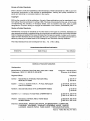
The concerned Technical Committee responsible for preparation of this standard has reviewed the
provisions of the following International publications and has decided that they are acceptable for use
in conjunction with this standard:
IEC 113
Diagrams, charts, tables
IEC 417 (1973)
Graphical symbols for use on equipment.
of single sheets
IEC 950 (1991)
Safety of information technology equipment,
equipment (since revised in 1999)
IEC 1010-1 (1 990)
Safety requirements for electrical equipment for measurement,
and laboratory use — Part 1: General requirements
control
ISO 216:1975
Writing paper and certain classes of printed matter — Trimmed
A and B series
sizes —
Only the English language text of the International
Indian Standard.
Index, survey and compilation
including electrical
Standard has been retained while adopting
business
it in this
-.
Bureau of Indian Standards
BIS is a statutory institutiorl established under the Bureau of/rtdkm Standards Act, 1986 to promote
harmonious development of the activities of standardization,
marking and quality certification of
goods and attending to connected matters in the country.
Copyright
BIS has the copyrighi of all its publications. No part of these publications maybe reproduced in any
form without the prior permission in writing of BIS. This does not preclude the free use, in the course
of implementing
the standard, of necessary details, such as symbols and sizes, type or grade
designations. Enquiries relating to copyright be addressed to the Director (Publications), BIS.
Review of Indian Standards
Amendments are issued to standardS as the need arises on the basis of comments. Standards are
also reviewed periodically; a standard along with amendments is reaffirmed when such review indicates
that no changes are needed; if the review indicates that changes are needed, it is taken up for revision.
Users of Indian Standards should ascertain that they are in possession of the latest amendments or
edition by referring to the latest issue of ‘BIS Catalogue’ and ‘Standards: Monthly Additions’.
This Indian Standard
has been developed
from Doc : No. LTD 21 (1852).
Amendments
Amend No.
Issued Since Publication
Date of Issue
Text Affected
BUREAU OF INDIAN STANDARDS
Headquarters:
Manak Bhavan, 9 Bahadur Shah Zafar Marg, New Delhi 110002
Telephones:
3230131,3233375,3239402
Telegrams : Manaksanstha
(Common to all offices)
Telephone
Regional Offices :
Central
: Manak Bhavan, 9 Bahadur Shah Zafar Marg
NEW DELHI 110002
Eastern
: 1/14 C. I.T. Scheme Vll M, V. 1.P. Road, Kankurgachi
CALCUTTA700054
Northern
: SCO 335-336, Sector 34-A, CHANDIGARH
Southern:
Western
Branches
{
3378499,3378561
{ 3378626,3379120
603843
{ 602025
160022
C. 1.T. Campus, IV Cross Road, CHENNAI 600113
: Manakalaya, E9 MlDC, Marol, Andheri (East)
MU MBA1400093
3237617
3233841
2350216,2350442
{ 2351519,2352315
{
8329295,8327858
8327891,8327892
AHMADABAD.
BANGALORE. BHOPAL. BHUBANESHWAR.
COIMBATORE.
FARIDABAD. GHAZIABAD.
GUWAHATI. HYDERABAD. JAIPUR. KANPUR.
LUCKNOW. NAGPUR. PATNA. PUNE. RAJKOT. THIRUVANANTHAPURAM.
Rinted st : Rsbhat
Offset Press, New Delhi-2