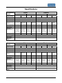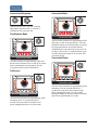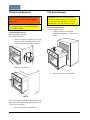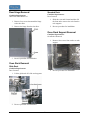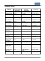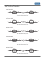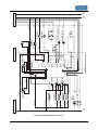
1
SERVICE NOTEBOOK
BUILT-IN ELECTRIC WALL OVEN
Models
VESO127SS
VESO527SS
VEDO127SS
VEDO527SS
VESO130SS
VESO530SS
VEDO130SS
VEDO530SS
DESO127SS
DESO527SS
DEDO127SS
DEDO527SS
DESO130SS
DESO530SS
DEDO130SS
DEDO530SS
VIKING RANGE CORPORATION
111 Front Street, Greenwood, Mississippi (MS) 38930 USA 662-455-1200
Important Information
SAVE THESE INSTRUCTIONS
REVIEW ALL SERVICE INFORMATION IN THE APPROPRIATE SERVICE MANUAL AND
TECHNICAL SHEETS BEFORE BEGINNING REPAIRS.
Pride and workmanship go into every product to provide our customers with quality products. It is possible,
however, that during its lifetime, a product may require service. Products should be serviced only by a
qualified service technician that is familiar with the safety procedures required in the repair and who is
equipped with the proper tools, parts, testing instruments, and the appropriate service manual.
Safety Information
Viking will not be responsible for injury or
property damage arising from service performed
by anyone other than Viking Factory Authorized
Service Agencies.
This manual uses safety symbols to inform the
qualified service technician of possible hazards
that may be present during a service procedure.
They will appear as follows:
WARNING: To avoid risk of serious
injury or death, repairs should not be
attempted by unauthorized personnel.
DANGER: IMMEDIATE HAZARDS
WHICH WILL RESULT IN SEVERE
PERSONAL INJURY OR DEATH.
CAUTION: VIKING will not be
practices which COULD result in severe
personal injury or death.
responsible for any injury or property damage
from improper service procedures. If
performing service on your own product, you
must assume responsibility for any personal
injury or property damage which may result.
CAUTION: Hazards or unsafe practices
To locate an authorized servicer, call:
WARNING: Hazards or unsafe
which COULD result in minor personal injury
or product or property damage.
Viking Technical Service
Phone No. 1-800-914-4799
Note to Customer
Address your written correspondence to:
Viking Preferred Service
111 Front Street
P.O. Drawer 956
Greenwood, MS 38935-0956
If you perform service on your own Viking
product, you must assume responsibility of
personal injury or property damage which may
result.
2
Professional Series Built-In Electric Ovens Warranty
One Year Full Warranty
Built-in electric ovens and all of their component parts and accessories, except as detailed below*, are warranted to be free from
defective materials or workmanship in normal household use for a period of twelve (12) months from the date of original retail
purchase. Viking Range Corporation, warrantor, agrees to repair or replace, at its option, any part which fails or is found to be
defective during the warranty period.
*Glass (including light bulbs), painted and decorative items are warranted to be free from defective materials or workmanship for
a period of ninety (90) days from the date of original retail purchase. ANY DEFECTS MUST BE REPORTED TO THE
SELLING DEALER WITHIN NINETY (90) DAYS FROM DATE OF ORIGINAL RETAIL PURCHASE.
Viking Range Corporation uses the most up-to-date processes and best materials available to produce all color finishes. However,
slight color variation may be noticed because of the inherent differences in painted parts and porcelain parts as well as differences
in kitchen lighting, product locations, and other factors.
Five Year Limited Warranty
Any bake element, broil element, or convection cook element which fails due to defective materials or workmanship in normal
household use during the second through the fifth year from the date of original retail purchase will be repaired or replaced, free
of charge for the part itself, with the owner paying all other costs, including labor.
Ten Year Limited Warranty
Any porcelain oven or porcelain inner door panel which rusts through due to defective materials or workmanship in normal
household use during the second through the tenth year from the date of original retail purchase will be repaired or replaced, free
of charge for the part itself, with the owner paying all other costs, including labor.
This warranty extends to the original purchaser of the product warranted hereunder and to each transferee owner of the product
during the term of the warranty.
This warranty shall apply to products purchased and located in the United States and Canada. Products must be purchased in the
country where service is requested. Warranty labor shall be performed by an authorized Viking Range Corporation service agency
or representative. Warranty shall not apply to damage resulting from abuse, accident, natural disaster, lose of electrical power to
the product for any reason, alteration, outdoor use, improper installation, improper operation, or repair or service of the product by
anyone other than an authorized Viking Range Corporation service agency or representative. This warranty does not apply to
commercial usage. Warrantor is not responsible for consequential or incidental damage whether arising out of breach of contract,
or otherwise. Some jurisdictions do not allow the exclusion or limitation of incidental of consequential damages, so the above
limitation or exclusion may not apply to you.
Owner shall be responsible for proper installation, providing normal care and maintenance, providing proof of purchase upon
request, and making the appliance reasonably accessible for service. If the product or one of its component parts contain a defect
or malfunction during warranty period, after a reasonable number of attempts by the warrantor to remedy the defects or
malfunction, the owner is entitled to either a refund or replacement of the product or its component part or parts. Warrantor’s
liability on any claim of any kind, with respect to the goods or services covered hereunder, shall in no case exceed the price of the
goods or service or part thereof which gives rise to the claim.
WARRANTY SERVICE: Under the terms of this warranty, service must be performed by a factory authorized Viking Range
Corporation service agent or representative. Service will be provided during normal business hours, and labor performed at
overtime or premium rates shall not be covered by this warranty. To obtain warranty service, contact the dealer from whom the
product was purchased, an authorized Viking Range Corporation service agent, or Viking Range Corporation. Provide model and
serial number and date of original purchase. For the name of your nearest authorized Viking Range Corporation service agency,
call the dealer from whom the product was purchased or Viking Range Corporation. IMPORTANT: Retain proof of original
purchase to establish warranty period.
The return of the Owner Registration Card is not a condition of warranty coverage. You should, however, return the Owner
Registration Card so the Viking Range Corporation can contact you should any question of safety arise which could affect you.
Any implied warranties of merchantability and fitness applicable to the above described bake element, broil element, convection
cook element, porcelain oven, or porcelain inner door panel are limited in duration to the period of coverage of the applicable
express written limited warranties set forth above. Some jurisdictions do not allow limitations on how long an implied warranty
lasts, so the above limitation may not apply to you. This warranty gives specific legal rights, and you may also have other rights
which may vary from jurisdiction to jurisdiction.
VIKING RANGE CORPORATION
111 Front Street, Greenwood, Mississippi (MS) 38930 USA 662-455-1200
Specifications are subject to change without notice.
For more product information, call 1-888-VIKING1 (845-4641), or visit our web
site at http://www.vikingrange.com
3
Table of Contents
Important Information ................................................................................................2
Safety Information ....................................................................................................................2
Note to Customer ......................................................................................................................2
General Overview.........................................................................................................6
Specifications.................................................................................................................7
Serial Number Location...............................................................................................8
Model Numbers ........................................................................................................................8
Serial Numbers .........................................................................................................................8
Operation.......................................................................................................................9
Oven Control Panel...................................................................................................................9
Oven Preheat Chart.................................................................................................................10
Oven Settings and Functions ..................................................................................................11
Clock and Timers....................................................................................................................13
Self-Clean Cycle .....................................................................................................................17
Service Procedures .....................................................................................................18
Part Locator.............................................................................................................................18
Service Situation Chart ...........................................................................................................19
Partial Oven Removal.............................................................................................................20
Full Oven Removal.................................................................................................................20
Door Assembly Removal........................................................................................................21
Door Gasket Removal.............................................................................................................21
Outer Door Panel Removal.....................................................................................................22
Outer Door Glass Removal.....................................................................................................22
Inner Door Glass Removal .....................................................................................................23
Door Handle Removal ............................................................................................................23
Door Hinge Removal ..............................................................................................................24
Oven Rack Removal ...............................................................................................................24
Glide Rack ..................................................................................................................24
Standard Rack .............................................................................................................24
Oven Rack Support Removal .................................................................................................24
Oven Light Bulb Removal......................................................................................................25
Side Lights ..................................................................................................................25
Top Light ....................................................................................................................25
Temperature Sensor (RTD) Removal .....................................................................................26
Broil Element Removal ..........................................................................................................27
Glass Enclosed............................................................................................................27
Tubular Style...............................................................................................................27
Bake Element Removal ..........................................................................................................28
Catalyst Removal....................................................................................................................28
Convection Baffle Removal....................................................................................................29
Convection Bake Element Removal .......................................................................................29
Convection Fan Motor Removal.............................................................................................30
Convection Fan Blade Removal .............................................................................................30
Access to Control Components...............................................................................................31
Partial Access..............................................................................................................31
4
Full Access ................................................................................................................. 31
Oven Function Selector Removal .......................................................................................... 32
Oven Thermostat Removal..................................................................................................... 32
Oven Control Board Removal................................................................................................ 33
Oven Light Switch Removal .................................................................................................. 33
Oven Cycle/Clean Indicator Lights Removal ........................................................................ 34
Oven Timer/Clock Removal .................................................................................................. 34
Digital Timer .............................................................................................................. 34
Analog Timer ............................................................................................................. 35
Convection Motor Capacitors Removal ................................................................................. 36
Thermal Cut-Out (TCO) Removal ......................................................................................... 37
Single Oven and Upper Double Oven........................................................................ 37
Lower Double Oven ................................................................................................... 37
Door Latch Assembly Removal ............................................................................................. 38
Single Oven and Upper Double Oven........................................................................ 38
Lower Double Oven ................................................................................................... 38
Door Switch Removal ............................................................................................................ 39
Single Oven and Upper Double Oven........................................................................ 39
Lower Double Oven ................................................................................................... 40
Oven Lights Transformer ....................................................................................................... 40
Blower Motor ......................................................................................................................... 41
Single Oven and Upper Double Oven........................................................................ 41
Lower Double Oven ................................................................................................... 42
Door Hinge Receiver Removal .............................................................................................. 43
Meat Probe Socket Removal .................................................................................................. 43
Troubleshooting ......................................................................................................... 44
Selector and Thermostat Characteristics ................................................................................ 44
Component Testing ................................................................................................................ 45
Troubleshooting Guide........................................................................................................... 47
Oven Control Board ............................................................................................................... 50
Communication between Control Boards on Double Ovens ................................................. 52
Strip Circuits and Schematics ................................................................................................ 53
5
General Overview
The Viking Built-In Electric Wall Ovens are available in various configurations. The oven features include
hidden bake elements, two broil element styles (glass enclosed or tubular), TruConvecTM convection motor
and bake element, and two types of oven controls. The ovens are available in single or double oven
configurations and come in two widths.
Model/Serial
Number Plate
(on bottom of
control panel)
Broil Element
(glass enclosed)
TruConvec
Element
(behind baffle)
Oven Light
Oven Racks
(3 upper oven;
3 lower oven)
Oven Light
Bake Element
(concealed)
Lower Oven
Professional Premiere Double Oven Shown
6
Specifications
Professional
Knobs
Select
Premiere
27" Wide
30" Wide
VESO130
VEDO130
VESO527
30" Wide
VESO127
2-Speed
2-Speed
(upper only)
2-Speed
2-Speed
(upper only)
2-Speed
2-Speed
(both ovens)
2-Speed
2-Speed
(both
ovens)
Oven Light
Meat Probe
Electrical
Requirements
One
One
One
One
Three
Three
Three
Three
No
No
No
No
Yes
Yes
Yes
Yes
4-Wire
w/ground,
30 Amp.
Connection
4-Wire
w/ground,
50 Amp.
Connection
4-Wire
w/ground,
30 Amp.
Connection
4-Wire
w/ground,
50 Amp.
Connection
4-Wire
w/ground,
30 Amp.
Connection
4-Wire
w/ground,
50 Amp.
Connection
24
40
24
40
24
40
Max Amp. Usage
Bake Rating
Broil Rating
TruConvec
Rating
VEDO127
27" Wide
Model Number
Clock
Bake Element
Broiler
Convection
System
VESO530
Digital
Digital
10-Pass Concealed Element
10-Pass Concealed Element
10-Pass Tubular
Designer
Knobs
VEDO527
Electric Infrared Glass Enclosed
4-Wire
4-Wire
w/ground, w/ground,
30 Amp.
50 Amp.
Connection Connection
24
3000 Watts
3000 Watts
4000 Watts
3500 Watts
3000 Watts
3000 Watts
Select
40
Premiere
27" Wide
30" Wide
DESO130
27" Wide
DEDO130
DESO527
30" Wide
Model Number
Clock
Bake Element
Broiler
Convection
System
DESO127
2-Speed
2-Speed
(upper only)
2-Speed
2-Speed
(upper only)
2-Speed
2-Speed
(both ovens)
2-Speed
2-Speed
(both
ovens)
Oven Light
Meat Probe
Electrical
Requirements
One
One
One
One
Three
Three
Three
Three
Yes
Yes
Max Amp. Usage
Bake Rating
Broil Rating
TruConvec
Rating
DEDO127
VEDO530
DEDO527
Digital
DESO530
DEDO530
Digital
10-Pass Concealed Element
10-Pass Concealed Element
10-Pass Tubular
Electric Infrared Glass Enclosed
No
No
No
No
Yes
Yes
4-Wire
w/ground,
30 Amp.
Connection
4-Wire
w/ground,
50 Amp.
Connection
4-Wire
w/ground,
30 Amp.
Connection
4-Wire
w/ground,
50 Amp.
Connection
4-Wire
w/ground,
30 Amp.
Connection
4-Wire
w/ground,
50 Amp.
Connection
24
40
24
40
24
40
4-Wire
4-Wire
w/ground,
w/ground,
30 Amp.
50 Amp.
Connection Connection
3000 Watts
3000 Watts
4000 Watts
3500 Watts
3000 Watts
3000 Watts
7
24
40
Serial Number Location
The model number and serial number are located on the data plate. The data plate is located on the top left
side of the oven cavity under the control panel.
Model Numbers
V E S O 1 2 7 S S
V = Professional
D = Designer
SS = Stainless
E = Electric
27 = 27" Wide
30 = 30" Wide
S = Single
D = Double
1 = Select
5 = Premiere
O = Oven
Serial Numbers
Serial Number 031006C0000000001
Month
Serial Number
Day
Year of Manufacture
8
Operation
Oven Control Panel
The Viking Built-In Electric Wall Ovens are available in two control panel options. Each oven has a Function
Selector and a Temperature Control. On double ovens, the Interior Oven Light Switch and Electronic Timing
Center are shared.
Electronic
Timing
Center
Oven Function
Selector
Oven Cycle Indicator
Interior Oven
Light Switch
OVEN
CLEAN
OVEN
CLEAN
OFF
SELF
CLEAN
Temperature
Control
Self-Clean Indicator
OFF
OFF
SELF
CLEAN
BAKE
OFF
BAKE
CLEAN
CLEAN
200
OVEN
LIGHT
LOW
BROIL
CONV.
BAKE
MED
BROIL
TRU
CONVEC
200
SET
LOW
BROIL
CONV.
BAKE
MED
BROIL
TRU
CONVEC
BROIL
300
BROIL
500
CLOCK/
PROBE
HI
BROIL
CONV.
ROAST
CONV.
BROIL
MIN/SEC
TIMER
SET
BAKE
TIME
HI
BROIL
400
UPPER OVEN
TEMPERATURE
OVEN FUNCTION
300
500
START
TIME
CONV.
ROAST
CONV.
BROIL
400
LOWER OVEN
TEMPERATURE
OVEN FUNCTION
(Professional Models)
Analog Clock with Digital Display
Interior Oven
Light Switch
(Premiere Models)
Oven Function
Selector
Digital Clock
(Select Models)
Oven Cycle Indicator
self
clean
Clean
off
conv.
bake
Oven
off
bake
low
broil
Clean
clean
200
Temperature
Control
Self-Clean Indicator
self
clean
Oven
off
off
bake
conv.
bake
low
broil
clean
200
broil
Oven Light
med
broil
hi
broil
conv.
broil
tru
convec
conv.
roast
Oven Function
med
broil
500
300
hi
broil
400
Oven Temperature
upper
timed
broil
min/sec
timer
bake
time
Set
start
time
probe
temp
Upper Oven
conv.
broil
tru
convec
conv.
roast
Oven Function
9
400
Oven Temperature
Lower Oven
(Designer Models)
500
300
manual
lower
timed
Oven Preheat Chart
Preheat is defined as the time from room temperature till the oven light cycles off. The following chart
represents a typical preheat cycle set at 300° F. The chart shows what elements are on and in what order. The
numbered columns represent the number of cycles the oven takes to complete preheat. All elements use
approximately 240V and cycle on and off for different lengths of time. Cycles for double ovens may vary.
Cycle
Inner broil
Outer broil
1.
X
X
2.
X
X
3.
X
X
X
X
X
X
X
X
X
X
X
X
7.
X
X
8.
X
X
X
X
X
X
X
X
X
10.
X
X
11.
X
X
X
X
X
X
X
X
X
13.
X
X
14.
X
X
15.
X
16.
X
X
X
X
X
X
X
X
X
X
18.
X
X
19.
X
20.
X
X
X
X
X
X
X
X
X
22.
X
X
X
24.
X
X
X
X
X
X
X
X
X
26.
X
X
X
28.
X
X
X
25.
27.
X
X
21.
23.
X
X
17.
X
X
29.
31.
32.
X
X
5.
30.
X
X
X
12.
Oven indicator light on
X
X
9.
Outer bake
X
4.
6.
Inner bake
X
X
X
X
X
X
X
X
X
X
Oven light cycles off. Preheat completed, all elements off until regular cycling takes over.
10
Low Broil
Oven Settings and Functions
Self-Clean
SELF
CLEAN
OFF
BAKE
CONV.
BAKE
LOW
BROIL
SELF
CLEAN
OFF
BAKE
MED
BROIL
LOW
BROIL
CONV.
BAKE
MED
BROIL
TRU
CONVEC
HI
BROIL
CONV.
BROIL
HI
BROIL
TRU
CONVEC
CONV.
BROIL
CONV.
ROAST
CONV.
ROAST
During the self-clean cycle, the oven reaches
elevated temperatures using the broil and bake
elements. The broil elements use approximately
240V and remain on during the self-clean cycle.
The bake elements use approximately 240V and
cycle on for a few seconds at various times during
the cleaning process.
low broil
Heat radiates only from the inner broil element.
The inner broil element uses approximately 240V
and pulses on for 25 seconds and off for 35
seconds.
High Broil
SELF
CLEAN
OFF
Convection Broil
BAKE
CONV.
BAKE
LOW
BROIL
MED
BROIL
HI
BROIL
SELF
CLEAN
TRU
CONVEC
CONV.
BROIL
CONV.
ROAST
OFF
BAKE
CONV.
BAKE
LOW
BROIL
MED
BROIL
HI
BROIL
TRU
CONVEC
CONV.
BROIL
CONV.
ROAST
high broil
Heat radiates from both broil elements. The broil
elements use approximately 240V and remain on
constantly.
convection broil
Heat radiates from both broil elements. The broil
elements use approximately 240V and pulse on
for 53 seconds and off for 7 seconds. Additionally,
the convection fan cycles on for 40 seconds,
cycles off for 7 seconds, and then cycles on in the
opposite direction for 40 seconds. This cycle then
repeats.
Medium Broil
SELF
CLEAN
OFF
BAKE
CONV.
BAKE
LOW
BROIL
MED
BROIL
HI
BROIL
TRU
CONVEC
CONV.
BROIL
CONV.
ROAST
Convection Defrost
SELF
CLEAN
OFF
OFF
BAKE
CLEAN
LOW
BROIL
CONV.
BAKE
MED
BROIL
TRU
CONVEC
200
BROIL
HI
BROIL
medium broil
CONV.
BROIL
CONV.
ROAST
300
500
400
Only the convection fan operates. No elements are
on. The convection fan cycles on in one direction
for 40 seconds, cycles off for 7 seconds, and then
cycles on in the opposite direction for 40 seconds.
This cycle then repeats.
Heat radiates from both broil elements. The broil
elements use approximately 240V and pulse on
for 40 seconds and off for 15 seconds.
11
Convection Dehydrate
SELF
CLEAN
OFF
Convection Bake
OFF
SELF
CLEAN
BAKE
OFF
BAKE
CLEAN
LOW
BROIL
CONV.
BAKE
MED
BROIL
TRU
CONVEC
200
CONV.
BAKE
LOW
BROIL
BROIL
HI
BROIL
CONV.
BROIL
CONV.
ROAST
MED
BROIL
300
TRU
CONVEC
500
HI
BROIL
400
CONV.
BROIL
CONV.
ROAST
With the selector set to TruConvec and the
temperature control on 200° F, warm air is
circulated by the convection fan.
Two-Element Bake
SELF
CLEAN
convection bake
OFF
BAKE
LOW
BROIL
CONV.
BAKE
MED
BROIL
TRU
CONVEC
HI
BROIL
CONV.
BROIL
The convection element uses approximately 240V
and cycles on and off at various times. The bake
and broil elements use 240V and pulse on and off
less frequently than the convection element.
Additionally, the convection fan cycles on for 40
seconds, cycles off for 7 seconds, and then cycles
on in the opposite direction for 40 seconds. This
cycle then repeats.
CONV.
ROAST
two-element bake
Convection Roast
The bake elements use approximately 240V and
the inner broil element cycles on and off at various
times to maintain the set temperature. See the
oven preheat chart for more information.
SELF
CLEAN
OFF
BAKE
CONV.
BAKE
LOW
BROIL
MED
BROIL
HI
BROIL
TRU
CONVEC
CONV.
BROIL
CONV.
ROAST
TruConvec
SELF
CLEAN
OFF
BAKE
CONV.
BAKE
LOW
BROIL
MED
BROIL
HI
BROIL
TRU
CONVEC
CONV.
BROIL
CONV.
ROAST
convection roast
The convection element uses approximately 240V
and pulses on for 40 seconds and off for 7
seconds. The convection fan remains in high
speed, changing direction every 40 seconds.
During the change in direction, the broil elements
pulse on for approximately 2 seconds.
TruConvec
The convection element uses approximately 240V
and pulses on for 53 seconds and off for 7
seconds. The convection fan remains in low
speed, changing direction every 40 seconds.
12
Clock and Timers
Setting the Min/Sec Timer
Digital Electronic Timing Center
The Min/Sec Timer is designed for accurate
timing and can be used at the same time the Bake
Time or Start Time functions are in use. It can be
used for timing up to 24 hours. When setting the
timer, the time displayed will increase in 1 minute
increments. When the timer counts down to 1
minute, the timer alarm will give two short beeps
and the display changes from hours:minutes to
seconds only.
The Electronic Timing Center is used to program
and control all timing functions. It has five display
and programming modes that are activated by the
four push buttons and the “SET” knob. Both the
Bake Time mode and the Min/Sec Timer mode
can be used to time cooking periods. These
features can be used at the same time when both
ovens are in use. Only the Bake Time and SelfCleaning modes shut the oven off automatically
when the timed program is over. One oven can
also be cleaned while timing foods in the other
oven using the Min/Sec Timer mode.
To program the Min/Sec Timer:
1. Press the “MIN/SEC TIMER” button. The
timer will display :00 and the word
TIMER will be displayed in the lower
right corner.
Setting the Time of Day
The time of day must be set before any other
program can be used. When the oven is first
connected to the power, the timer display will
show –:–.
2. Turn the “SET” knob until the desired
duration time is displayed.
The Min/Sec Timer is now programmed. An
alarm will sound at the end of the countdown. The
program can be canceled anytime by setting the
remaining time to 00:00. To change back to the
time of day, press the “CLOCK/PROBE” button.
Notice that a small clock will be displayed in the
upper right corner to indicate that a program is in
progress. The display will return automatically to
the Min/Sec Timer after a few seconds.
SET
CLOCK/
PROBE
MIN/SEC
TIMER
SET
BAKE
TIME
START
TIME
Timer Alarm
To program the time of day:
At the end of a Min/Sec Timer program or Bake
Time program, the alarm will consist of three
beeps, followed by two beeps every 10 seconds,
until the “MIN/SEC TIMER” button is pressed.
Whenever a valid function key is pressed or when
a control function starts automatically, one beep
will be sounded. When an invalid function key is
pressed, two beeps will be sounded.
1. Press the “CLOCK/PROBE” * button
once. 12:00 will be displayed with the
word SET in the upper right corner.
2. Turn the “SET” knob until the correct
time of day is displayed. AM and PM are
not indicated.
3. Press the “CLOCK/PROBE” button
again. The word SET will disappear and
the correct time is now set into the timer.
The time of day cannot be changed while there is
a Bake Time or Start Time cycle programmed into
the timer.
13
Setting the Automatic Start Time Bake
Program
the display indicating that the Bake
Time program has been set.
NOTE
The Bake Time and Start Time modes of the timer
can be used to automatically turn the oven on and
off at a preselected time.
For Double Ovens, the word DELAY will show
with either UPPER OVEN or LOWER OVEN,
depending on which oven has been selected.
3. Set the Oven Function selector to the
desired function –BAKE, CONVECTION
BAKE, OR TRUCONVEC, etc.
SET
CLOCK/
PROBE
MIN/SEC
TIMER
SET
BAKE
TIME
4. Set the temperature control knob to the
desired baking temperature. The
automatic time bake program is now set.
START
TIME
NOTE
The display will continue to show the amount of
bake time that was programmed (this will remain
until the programmed start time is reached). You
can return the display to clock mode by pressing
the “CLOCK/PROBE” button – Notice that a
small clock will be displayed in the upper right
corner to indicate that a program is in progress.
Switch back to the timer mode by pressing the
“BAKE TIME” button.
To set the Automatic Time Bake Program:
1. Set the start time:
For Single Ovens – Program the start
time by pressing the “START TIME”
button and turning the “SET” knob
until the desired start time is
displayed. This is the time of day you
want the food to begin cooking.
5. When the specified time is reached, the
oven will automatically turn on. It will
bake for the programmed amount of time
at the selected temperature.
For Double Ovens – Press the
“START TIME” button once to set
the starting time for the upper oven
(UPPER OVEN will show on the
display). Press the “START TIME”
button twice to set the starting time
for the lower oven (LOWER OVEN
will show on the display). Then,
program the start time by turning the
“SET” knob until the desired start
time is displayed. This is the time of
day you want the food to begin
cooking.
NOTE
Setting the remaining duration time to :00 will
cancel the Automatic Bake program. At one
minute from the end of the specified bake
program, the oven timer will beep once. At the
end of the specified bake program, the oven will
automatically turn off and the timer will sound a
series of three beeps.
6. Press the “START TIME” button to end
the program. The display will then return
to displaying the time.
2. Set the desired baking time:
Once the start time is set, the display
will switch to :00 and the words SET,
COOK, and TIME will appear on the
right side of the display. You will now
enter the desired baking time. Turn
the “SET” knob until the desired
baking time is displayed in hours and
minutes. Once the desired bake time
is set, the word SET will disappear
and the word DELAY will appear in
7. Turn the temperature control knob and
oven function selector to off.
14
NOTE
Setting the Analog Display
Press any function button to clear a completed
cycle or function.
The time-of-day must be set before any other
program can be used. When the oven is first
connected to the power, the digital display will
show 00:00.
Setting the Bake Time Program
The Bake Time program is used for controlled
timing of baked or roasted foods. At the end of the
timed cycle, the oven automatically turns off.
Setting the Automatic Start Time Bake
Program
The Bake Time program is used for controlled
timing of baked or roasted foods. At the end of the
timed cycle, the oven automatically turns off.
To Set the Bake Time Program
min/sec
timer
bake
time
Set
start
time
1. Turn the “manual” knob to “upper timed”
or “lower timed” position, depending
upon the oven mode and oven being used.
probe
temp
2. Set the Oven Function Selector to the
BAKE, CONVECTION BAKE, or
TRUCONVEC position, depending upon
the type of baking being used.
To program the time-of-day:
1. Push and hold the “min/sec timer” and
“bake time” buttons at the same time.
3. Set the temperature control knob to the
desired temperature and allow for
preheating.
2. Turn the “Set” knob until correct time is
displayed on the digital clock.
3. Release the buttons.
Setting the Min/Sec Timer
4. Press and release the “bake time” button.
The timer will display :00 with the words
SET and COOK in the upper right corner
of the digital display.
The Min/Sec Timer is designed for accurate
timing and can be used at the same time the Bake
Time or Start Time functions are in use. It can be
used for timing up to 24 hours.
5. Turn the “Set” knob until the desired
baking time is displayed in hours and
minutes. The cook time/remaining time
and the word COOK will be displayed.
The analog clock will automatically set after the
digital time is set.
The word COOK will flash and the tone will
sound three times when the time is completed;
oven will turn off. The tone will sound twice
every ten seconds after completion until timer
function is cleared.
To program the Min/SecTimer
4. Push and release the “min/sec timer”
button.
5. Rotate “Set” knob until desired duration
of time is displayed. Timer starts seconds
after “Set” knob stops rotating. A tone
indicates the timer has started.
6. Turn off the oven.
When the timer has one minute remaining, the
timer will sound twice and begin to countdown by
seconds. A tone will sound three times indicating
the time is complete and twice every ten seconds
after completion until timer function is cleared.
15
NOTE
To set the Automatic Time Bake
Program
For Double Ovens, the word DELAY will show
with either UPPER OVEN or LOWER OVEN,
depending on which oven has been selected.
3. Set the Oven Function selector to the
desired function – BAKE,
CONVECTION BAKE, OR
TRUCONVEC, etc.
4. Set the temperature control knob to the
desired baking temperature.
5. The automatic time bake program is now
set.
NOTE
min/sec
timer
bake
time
Set
start
time
The display will continue to show the amount of
bake time that was programmed (this will remain
until the programmed start time is reached). You
can return the display to clock mode by pressing
the “probe/temp” button – Notice that a small
clock will be displayed in the upper right corner to
indicate that a program is in progress. Switch back
to the timer mode by pressing the “bake time”
button.
probe
temp
1. Set the start time:
a. For Single Ovens – Program the start
time by pressing the “start time”
button and turning the “Set” knob
until the desired start time is
displayed. This is the time of day you
want the food to begin cooking.
6. When the specified time is reached, the
oven will automatically turn on. It will
bake for the programmed amount of time
at the selected temperature.
b. For Double Ovens – Press the “start
time” button once to set the starting
time for the upper oven (UPPER
OVEN will show on the display).
Press the “start time” button twice to
set the starting time for the lower
oven (LOWER OVEN will show on
the display). Then, program the start
time by turning the “Set” knob until
the desired start time is displayed.
This is the time of day you want the
food to begin cooking.
NOTE
At one minute from the end of the specified bake
program, the oven timer will beep once. At the
end of the specified bake program, the oven will
automatically turn off and the timer will sound a
series of three beeps. This will continue until the
“start time” button is pressed. The display will
then return to displaying the time.
2. Set the desired baking time:
NOTE
Once the start time is set, the display will
switch to :00 and the words SET, COOK,
and TIME will appear on the right side of
the display. You will now enter the
desired baking time. Turn the “Set” knob
until the desired baking time is displayed
in hours and minutes. Once the desired
bake time is set, the word SET will
disappear and the word DELAY will
appear in the display indicating that the
Bake Time program has been set.
Setting the remaining duration time to :00 will
cancel the Automatic Bake program.
16
4. The clean indicator light will remain on
until the self-clean is completed or
interrupted and the oven temperature
drops to a safe temperature. A complete
cycle is approximately 3 1/2 hours with an
additional 30 minutes needed for the oven
to cool down enough for the door latch to
disengage.
Self-Clean Cycle
This oven features an automatic pyrolytic selfcleaning cycle. During this cycle, the oven reaches
elevated temperatures in order to burn off soil and
deposits. An integral smoke eliminator helps
reduce odors associated with the soil burn-off. A
powder ash residue is left in the bottom of the
oven after completion of the Self-Clean cycle. The
door latch is automatically activated after
selecting the Self-Clean setting. The latch ensures
that the door cannot be opened while the oven
interior is at clean temperatures.
NOTE
A fan noise will be heard during the self-clean
cycle and will continue to run for the 3 1/2 hour
duration of the self-clean cycle.
Before starting the Self-Clean cycle:
5. When the cycle is completed, turn the
oven selector and temperature control
knob to the off position. When the oven
has completely cooled, open door and
remove any ash from the oven surfaces
with a damp cloth.
1. Remove the oven racks and any other
items/utensils from the oven. The high
heat generated during the cleaning cycle
can discolor, warp, and damage these
items. Do not use foil or liners in the
oven. During the Self-Clean cycle, foil
can burn or melt and damage the oven
surface.
To stop the Self-Clean cycle:
To cancel or interrupt the self-cleaning cycle, turn
the temperature control knob and the oven
function selector knob to OFF. When the oven
temperature drops to a safe temperature, the
automatic door latch will release and the oven
door can be opened. When the oven has
completely cooled, remove any ash from the oven
surfaces with a damp sponge or cloth.
2. Wipe off any large spills from the oven
bottom and sides. Never use oven cleaners
inside a self-cleaning oven or on raised
portions of the door.
3. Some areas of the oven must be cleaned
by hand before the cycle begins. Soils in
these areas will be baked on and very
difficult to clean if not removed first.
Clean the door up to the gasket, the door
frame, and up to 2 inches inside the frame
with detergent and hot water. Rinse
thoroughly and dry.
To start the Self-Clean cycle:
1. Close the door completely.
2. Turn the oven selector knob to self-clean.
3. Turn the temperature control knob to
clean. The clean indicator light will come
on. Within 30 seconds, the automatic door
latch engages and the oven indicator light
comes on. The oven indicator light will
remain on until the oven reaches the selfclean temperature and will then cycle on
and off during the self-clean cycle.
17
Service Procedures
Part Locator
18
Service Situation Chart
TASK
Door Assembly
Inner Door Glass
Outer Door Glass
Door Hinge
Door Handle
Door Gasket
Oven Racks
Oven Rack Supports
Oven Temperature Sensor
Broil Elements
Bake Elements
Convection Bake Elements
Convection Motor Assembly
Oven Light Bulbs
Oven Catalyst (Smoke Elim.)
Oven Function Selector
Oven Thermostat
Oven Control Board
Oven Light Switch
Oven Cycle/Clean Light
Oven Timer/Clock
Capacitors
Door Latch Assembly (Upper)
Single
Unit
Double
Unit
Front
Serviceable
X
X
X
X
X
X
X
X
X
X
X
X
X
X
X
X
X
X
X
X
X
X
X
X
X
X
X
X
X
X
X
X
X
X
X
X
X
X
X
X
X
X
X
X
X
X
X
X
X
X
X
X
X
X
X
X
X
X
X
X
X
X
X
X
X
X
X
X
X
X
X
Door Latch Assembly (Lower)
Door Switch (Upper)
X
Door Switch (Lower)
Lights Transformer
Blower Motor (Upper)
X
X
Blower Motor (Lower)
TCO (Upper)
X
TCO (Lower)
Door Hinge Receiver
Meat Probe Socket
X
X
19
Partial
Removal
Required
Full
Removal
Required
X
X
X
X
X
X
X
X
X
X
X
X
X
X
X
X
X
X
Partial Oven Removal
Full Oven Removal
WARNING: Disconnect power to oven
CAUTION: The oven is heavy. Removal
from the installation will require two people.
Use care when removing the oven to avoid
damaging the oven, wall, cabinet, or floor.
before servicing. Follow lockout/tagout
procedures.
CAUTION: The oven is heavy. Use care
when sliding oven out to avoid damaging the
oven, wall, or cabinet.
Condition Requirements:
Oven Partially Removed
1. Continue to slide oven from the
installation and place it on a protected
surface.
Condition Requirements:
Door Assembly Removed
Oven Racks Removed
1. Remove two screws (single oven) or four
screws (double oven) that attach the side
of the outer trim to the wall or cabinet.
2. Slide the oven forward.
2. Reverse procedure for installation.
NOTE
If the oven is advanced past the balance point, use
appropriate bracing under the front of the oven to
avoid excessive tipping.
3. Reverse procedure for installation.
20
Door Assembly Removal
Door Gasket Removal
CAUTION: Use care when handling the door
assembly. Do not lift or carry the door by the
handle.
Condition Requirements:
Door Lowered
1. Insert a narrow tool or small flat-blade
screwdriver into the center of each clip
and pry upward.
Condition Requirements:
Door Lowered
1. Place pin in pin hole.
2. Remove the door gasket from two holes in
the bottom of the door liner.
2. Remove screw and hinge trim from oven.
3. Close door until pins stop door.
3. Reverse procedure for installation.
4. Lift door up and out.
NOTE
To adjust the door, turn the adjustment screw
clockwise to raise the door or turn it
counterclockwise to lower the door. The oven
must be partially removed to adjust the door.
5. Reverse procedure for installation.
21
Outer Door Panel Removal
Outer Door Glass Removal
Condition Requirements:
Outer Door Panel Removed
CAUTION: Use care when handling the door
assembly. Do not lift or carry the door by the
handle.
1. Remove four screws that attach the outer
door glass assembly to the heat barrier.
2. Remove the outer door glass from the heat
barrier.
Condition Requirements:
Door Assembly Removed
1. Place the door handle side down on a
protected surface.
2. Remove seven screws that attach the outer
door panel to the door liner.
3. Reverse procedure for installation.
3. Turn the door over and lift the outer door
panel from the door liner.
4. Reverse procedure for installation.
22
Inner Door Glass Removal
Door Handle Removal
Condition Requirements:
Outer Door Glass Removed
CAUTION: Use care when handling the door
assembly. Do not lift or carry the door by the
handle.
1. Remove six screws that attach the heat
barrier to the door liner.
Condition Requirements:
Outer Door Panel Removed
1. Remove four 3/8 inch bolts that hold the
door handle to the outer panel.
2. Lift the heat barrier from the door liner.
2. Remove the door handle from the outer
panel.
3. Lift the inner door glass from the door
liner.
3. Reverse procedure for installation.
4. Reverse procedure for installation.
23
Door Hinge Removal
Standard Rack
Condition Requirements:
Outer Door Panel Removed
Condition Requirements:
Door Lowered
1. Remove four screws that attach the hinge
to the door liner.
1. Slide the oven rack forward and then lift
the front end to remove the rack from the
rack supports.
2. Remove the hinge from the door liner.
2. Reverse procedure for installation.
Oven Rack Support Removal
Condition Requirements:
Oven Racks Removed
1. Remove four screws from each oven rack
support.
3. Reverse procedure for installation.
Oven Rack Removal
Glide Rack
Condition Requirements:
Door Lowered
2. Reverse procedure for installation.
1. Lift the glide rack off of the rack supports.
2. Reverse procedure for installation.
24
Oven Light Bulb Removal
Top Light
Side Lights
The top light bulb is located in the cavity and uses
a 20W bulb.
The side light bulbs are located in the oven cavity
and use a 5W bulb.
WARNING: Disconnect power to oven
before servicing. Follow lockout/tagout
procedures.
WARNING: Disconnect power to oven
before servicing. Follow lockout/tagout
procedures.
CAUTION: Do not touch bulb with bare
hands. Clean off any signs of oil from the bulb
and handle with a soft cloth.
CAUTION: Do not touch bulb with bare
hands. Clean off any signs of oil from the bulb
and handle with a soft cloth.
Condition Requirements:
Door Lowered
5. Carefully pry the glass cover on both sides
until it releases.
Condition Requirements:
Door Lowered
1. Unsnap the glass cover at the opposite end
from the metal hinge.
6. Firmly grasp the bulb and pull out.
2. Firmly grasp the bulb and pull out.
1
2
3
4
7. Replace with a 12V-20W bulb.
3. Replace with a 64405, 12V-5W bulb.
8. Replace the light cover by pressing it back
into place.
4. Replace the light cover by first sliding it
into the metal hinge and then snapping
closed on opposite end.
25
Temperature Sensor (RTD)
Removal
3. Apply side pressure to the sensor
connector to secure the connector against
the opening in the oven liner.
The Temperature Sensor (RTD) is located in the
back of the oven cavity. It is used to sense oven
temperature.
4. While maintaining side pressure on the
connector, disconnect the old sensor and
connect the new sensor.
WARNING: Disconnect power to oven
before servicing. Follow lockout/tagout
procedures.
Condition Requirements:
Door Assembly Removed
Oven Racks Removed
1. Remove two screws that attach the sensor
to the back of the oven liner.
NOTE
When reinstalling the oven sensor, it may be
helpful to insert a small screwdriver or awl into
the connector and push the wiring and connector
into place.
2. Pull the sensor from the liner until the
sensor connector protrudes into the oven
cavity.
5. Install two screws that attach the sensor to
the back of the oven liner.
26
Broil Element Removal
Tubular Style
Glass Enclosed
WARNING: Disconnect power to oven
before servicing. Follow lockout/tagout
procedures.
WARNING: Disconnect power to oven
before servicing. Follow lockout/tagout
procedures.
Condition Requirements:
Door Assembly Removed
1. Remove six screws that hold the broil
assembly to the top of the oven cavity.
Condition Requirements:
Door Assembly Removed
1. Remove 13 screws that hold the broil
assembly to the oven cavity.
2. Remove two screws that hold the broil
assembly to the back of the oven cavity.
2. Carefully lower the broil assembly.
3. Carefully lower the broil assembly.
3. Pull four connectors through the oven
cavity wall.
4. Pull four connectors through the oven
cavity wall.
4. Mark and disconnect the four wires from
the broil assembly.
5. Mark and disconnect the four wires from
the broil assembly.
5. Separate the housing from the broil
assembly.
6. Reverse procedure for installation.
6. Reverse procedure for installation.
27
Bake Element Removal
4. Slide the bake element partially out, mark
and disconnect the four wires from the
bake element.
WARNING: Disconnect power to oven
before servicing. Follow lockout/tagout
procedures.
Condition Requirements:
Door Assembly Removed
1. Remove the two screws that hold the bake
element access panel to the oven frame.
5. Remove the bake element from the oven
2. Remove the insulation from the recess.
6. Reverse procedure for installation.
Catalyst Removal
Condition Requirements:
Convection Baffle Removed
1. Remove the two screws that hold the oven
catalyst to the top, left, rear corner of the
oven liner.
3. Remove the two screws that attach the
bake element to the element shelf.
2. Pull down the oven catalyst.
3. Reverse procedure for installation.
28
Convection Baffle Removal
Convection Bake Element
Removal
Condition Requirements:
Door Assembly Removed
1. Remove four screws and the oven rack
support from the oven cavity.
WARNING: Disconnect power to oven
before servicing. Follow lockout/tagout
procedures.
Condition Requirements:
Convection Baffle Removed
1. Remove two screws that hold the
convection element to the rear of the oven
cavity.
2. Remove three screws that attach the
convection baffle to the oven cavity.
2. Disconnect two wires from the convection
element.
3. Reverse procedure for installation.
3. Reverse procedure for installation.
29
Convection Fan Motor Removal
Convection Fan Blade Removal
WARNING: Disconnect power to oven
Condition Requirements:
Convection Baffle Removed
1. Loosen the fan setscrew counterclockwise
two to three turns.
before servicing. Follow lockout/tagout
procedures.
2. Remove the 1/2 inch nut from the fan.
Condition Requirements:
Convection Baffle Removed
1. Remove the six screws that hold the
convection fan assembly to the rear of the
oven liner.
3. Lift the fan blade from the fan motor
shaft.
NOTE
Upon reassembly, tighten the 1/2 inch fan nut
BEFORE tightening setscrew to the flat surface on
the fan motor shaft.
2. Disconnect the convection fan motor wire
harness.
4. Reverse procedure for installation.
3. Reverse procedure for installation.
30
Access to Control Components
Full Access
The Control Components are located on top of the
oven. Access is required in order to perform many
troubleshooting procedures and remove some
control components. The single and double ovens
are similar. The upper oven controls are on the left
side and the lower oven controls are on the right.
Partial or full access may be required depending
on the component being tested or removed.
DANGER: ONLY TRAINED AND
QUALIFIED TECHNICIANS SHOULD
TROUBLESHOOT THIS OVEN WITH
POWER CONNECTED. USE EXTREME
CARE TO AVOID ELECTRIC SHOCK
WHEN TESTING COMPONENTS.
WARNING: Disconnect power to oven
Partial Access
before servicing. Follow lockout/tagout
procedures.
DANGER: ONLY TRAINED AND
CAUTION: Some areas of the oven
QUALIFIED TECHNICIANS SHOULD
TROUBLESHOOT THIS OVEN WITH
POWER CONNECTED. USE EXTREME
CARE TO AVOID ELECTRIC SHOCK
WHEN TESTING COMPONENTS.
interior are sharp; wear protective gloves to
avoid injury.
Condition Requirements:
Oven Fully Removed
1. Remove six screws and the top rear
component access panel.
WARNING: Disconnect power to oven
before servicing. Follow lockout/tagout
procedures.
CAUTION: Some areas of the oven
interior are sharp; wear protective gloves to
avoid injury.
Condition Requirements:
Oven Partially Removed
1. Remove eight screws and the top front
component access panel.
2. Reverse procedure for installation.
2. Reverse procedure for installation.
31
Oven Function Selector Removal
Oven Thermostat Removal
The Oven Function Selector is located on the
control panel. It is used to select the oven function
(i.e., Bake, Broil, and TruConvec, etc). It is a
potentiometer and has a black cover on the rear to
distinguish it from the thermostat which has a red
cover.
The Oven Thermostat is located on the control
panel. It is used to set the oven temperature. It is a
potentiometer and has a red cover on the rear to
distinguish it from the oven function selector
which has a black cover.
WARNING: Disconnect power to oven
WARNING: Disconnect power to oven
before servicing. Follow lockout/tagout
procedures.
before servicing. Follow lockout/tagout
procedures.
CAUTION: Some areas of the oven
CAUTION: Some areas of the oven
interior are sharp; wear protective gloves to
avoid injury.
interior are sharp; wear protective gloves to
avoid injury.
Condition Requirements:
Partial Access to Control Components
1. With the knob in the off position, remove
the knob from the thermostat.
Condition Requirements:
Partial Access to Control Components
1. With the knob in the off position, remove
the knob from the oven function selector.
2. Remove two screws, bezel, and the
thermostat from the control panel.
2. Remove two screws, bezel, and the oven
function selector from the control panel.
3. Disconnect connector from the thermostat.
3. Disconnect connector from the oven
function selector.
4. Reverse procedure for installation.
4. Reverse procedure for installation.
32
Oven Control Board Removal
Oven Light Switch Removal
The Oven Control Board is located above the oven
cavity in the front of the component compartment.
It is used to control all oven functions. Double
ovens have two control boards, one for each oven.
The upper oven control board is on the left and the
lower oven control board is on the right.
The Oven Light Switch is located on the control
panel. It is used to turn the oven lights on or off.
WARNING: Disconnect power to oven
CAUTION: Some areas of the oven
WARNING: Disconnect power to oven
before servicing. Follow lockout/tagout
procedures.
interior are sharp; wear protective gloves to
avoid injury.
before servicing. Follow lockout/tagout
procedures.
CAUTION: Some areas of the oven
Condition Requirements:
Partial Access to Control Components
1. Pull to remove the button from the switch.
interior are sharp; wear protective gloves to
avoid injury.
2. Remove the knurled nut and the light
switch from the control panel.
Condition Requirements:
Partial Access to Control Components
1. Disconnect all connectors from the control
board.
3. Disconnect the light switch wires at the
connectors.
2. Remove six screws and the control board
from the oven
3. Reverse procedure for installation.
4. Reverse procedure for installation.
33
Oven Cycle/Clean Indicator
Lights Removal
Oven Timer/Clock Removal
The Oven Timer/Clock is located on the control
panel. It is used to control the meat probe, bake
time, and automatic bake functions. The digital
and analog styles are replaced using the same
procedures.
The Oven Cycle/Clean Indicator Lights are
located on the control panel. The Oven Cycle
Indicator Light is used to indicate when an oven
element is on. The Clean Indicator Light is on
when the oven is in self-clean mode.
Digital Timer
WARNING: Disconnect power to oven
WARNING: Disconnect power to oven
before servicing. Follow lockout/tagout
procedures.
before servicing. Follow lockout/tagout
procedures.
CAUTION: Some areas of the oven
CAUTION: Some areas of the oven
interior are sharp; wear protective gloves to
avoid injury.
interior are sharp; wear protective gloves to
avoid injury.
Condition Requirements:
Partial Access to Control Components
1. Hold the red lens and slide off the
indicator light. The indicator light will
only slide in one direction.
Condition Requirements:
Partial Access to Control Components
1. Pull to remove one knob and four buttons
from the digital timer.
2. Disconnect two connectors from the
indicator light.
2. Remove two screws from each side of the
control panel assembly.
3. Lower the control panel assembly forward
leaving the panel in the three tabs along
the bottom of the panel.
3. Reverse procedure for installation.
34
4. Disconnect connectors from the timer.
The number of connectors will vary
depending on the number of ovens and
features available.
Analog Timer
5. Remove four screws and the digital timer
from the control panel assembly.
before servicing. Follow lockout/tagout
procedures.
WARNING: Disconnect power to oven
CAUTION: Some areas of the oven
interior are sharp; wear protective gloves to
avoid injury.
Condition Requirements:
Partial Access to Control Components
1. Pull to remove one knob from the analog
timer.
6. Remove two screws and mounting bracket
from each side of the timer.
NOTE
Follow steps 2 through 6 of the digital timer
removal. The analog timer will look slightly
different; however the procedure is the same.
2. Reverse procedure for installation.
7. Reverse procedure for installation.
35
Convection Motor Capacitors
Removal
CAUTION: Use care when lifting the
control panel assembly from the tabs. The
weight of the control panel assembly could
pull wires from connectors. It will be
necessary to remove some connectors from the
control panel assembly or the control board to
gain access to the bottom of the capacitor. Tag
and mark any connectors before removal.
The Convection Motor Capacitors are located
above the oven cavity in the front of the
component compartment. They are used to control
the direction and speed of convection motor. Each
convection motor has two capacitors.
WARNING: Disconnect power to oven
3. Lift the control panel off three tabs.
before servicing. Follow lockout/tagout
procedures.
WARNING: A capacitor may maintain
CAUTION: Some areas of the oven
a charge even after power has been
disconnected. Use care when discharging
the capacitor to avoid electric shock.
interior are sharp; wear protective gloves to
avoid injury.
Condition Requirements:
Partial Access to Control Components
1. Remove two screws from each side of the
control panel assembly.
4. Discharge the capacitor and then
disconnect two connectors from the
capacitor.
5. Remove 13mm nut and capacitor from the
oven.
2. Lower the control panel assembly forward
leaving the panel in the three tabs along
the bottom of the panel.
6. Reverse procedure for installation.
36
Thermal Cut-Out (TCO) Removal
Lower Double Oven
Single Oven and Upper Double Oven
The Thermal Cut-Out (TCO) for the lower double
oven is located between the upper and lower oven
cavities. It is used as a safety device to prevent
overheating of electrical components
The Thermal Cut-Out (TCO) for the single oven
and upper double oven is located above the oven
cavity in front of the capacitors. It is used as a
safety device to prevent overheating of electrical
components.
WARNING: Disconnect power to oven
before servicing. Follow lockout/tagout
procedures.
WARNING: Disconnect power to oven
before servicing. Follow lockout/tagout
procedures.
CAUTION: Some areas of the oven
interior are sharp; wear protective gloves to
avoid injury.
CAUTION: Some areas of the oven
interior are sharp; wear protective gloves to
avoid injury.
Condition Requirements:
Door Assembly Removed
1. Remove two screws and the lower door
latch access panel.
Condition Requirements:
Partial Access to Control Components
1. Remove two screws from the upper oven
TCO.
2. Remove two ¼ hex screws from the lower
oven TCO.
2. Disconnect two connectors from the TCO.
3. Disconnect two connectors from the TCO.
3. Reverse procedure for installation.
4. Reverse procedure for installation.
37
Door Latch Assembly Removal
Lower Double Oven
Single Oven and Upper Double Oven
The Door Latch Assembly for the lower double
oven is located between the upper and lower oven
cavities. It is used as a safety device during the
self-clean cycle.
The Door Latch Assembly for the single oven and
upper double oven is located above the oven
cavity in the front of the component compartment.
It is used as a safety device during the self-clean
cycle.
WARNING: Disconnect power to oven
before servicing. Follow lockout/tagout
procedures.
WARNING: Disconnect power to oven
CAUTION: Some areas of the oven
before servicing. Follow lockout/tagout
procedures.
interior are sharp; wear protective gloves to
avoid injury.
CAUTION: Some areas of the oven
interior are sharp; wear protective gloves to
avoid injury.
Condition Requirements:
Door Assembly Removed
1. Remove two screws and the lower door
latch access panel.
Condition Requirements:
Partial Access to Control Components
1. Remove four screws and upper door latch
access panel.
2. Remove two 1/4 hex screws from the door
latch assembly.
2. Remove two 1/4 hex screws from the door
latch assembly.
3. Disconnect six connectors from the door
latch assembly.
3. Disconnect six connectors from the door
latch assembly.
4. Reverse procedure for installation.
4. Reverse procedure for installation.
38
Door Switch Removal
2. Pull the door switch through the access
hole.
Single Oven and Upper Double Oven
3. Disconnect two connectors from the door
switch.
The Door Switch for the single oven and upper
double oven is located above the oven cavity in
the front of the component compartment. It is used
to sense when the upper oven door is open.
WARNING: Disconnect power to oven
before servicing. Follow lockout/tagout
procedures.
CAUTION: Some areas of the oven
interior are sharp; wear protective gloves to
avoid injury.
Condition Requirements:
Partial Access to Control Components
1. Remove one screw from the door switch
and slide the door switch actuator out of
the guide.
4. Reverse procedure for installation.
39
Lower Double Oven
Oven Lights Transformer
The Door Switch for the lower double oven is
located between the upper and lower oven
cavities. It is used to sense when the lower oven
door is open.
The Oven Lights Transformer is located above the
oven cavity in the rear of the component
compartment. It is used to reduce the 240 volt
supply power to 12 volts for the oven lights.
WARNING: Disconnect power to oven
WARNING: Disconnect power to oven
before servicing. Follow lockout/tagout
procedures.
before servicing. Follow lockout/tagout
procedures.
CAUTION: Some areas of the oven
CAUTION: Some areas of the oven
interior are sharp; wear protective gloves to
avoid injury.
interior are sharp; wear protective gloves to
avoid injury.
Condition Requirements:
Oven Partially Removed
1. Remove two screws and the lower door
latch access panel.
Condition Requirements:
Full Access to Control Components
1. Disconnect two connectors from the blue
wires of the transformer.
2. Disconnect two connectors from the black
wires of the transformer.
2. Remove one screw from the door switch
and slide the door switch actuator out of
the guide.
3. Remove two screws and the transformer
from the oven.
3. Disconnect two connectors from the door
switch.
4. Reverse procedure for installation.
4. Reverse procedure for installation.
40
Blower Motor
2. Remove one screw and the blower guard
from the oven.
Single Oven and Upper Double Oven
3. Disconnect two connectors from the
blower motor.
The Blower Motor for the single oven and upper
double oven is located above the oven cavity in
the rear of the component compartment. It is used
to reduce air temperature in the component
compartment.
WARNING: Disconnect power to oven
before servicing. Follow lockout/tagout
procedures.
CAUTION: Some areas of the oven
interior are sharp; wear protective gloves to
avoid injury.
Condition Requirements:
Full Access to Control Components
1. Remove three screws from the back of the
oven that hold the blower motor.
4. Reverse procedure for installation.
41
Lower Double Oven
2. Remove four screws from the blower
motor mounting bracket.
The Blower Motor for the lower double oven is
located on the back of the oven cavity. It is used to
reduce air temperature between the oven cavities.
3. Disconnect two connectors from the
blower motor.
4. Remove three screws that attach the
blower motor to the mounting bracket.
WARNING: Disconnect power to oven
before servicing. Follow lockout/tagout
procedures.
CAUTION: Some areas of the oven
interior are sharp; wear protective gloves to
avoid injury.
Condition Requirements:
Full Access to Control Components
1. Remove 29 screws from the back of the
oven that hold on the back cover.
5. Reverse procedure for installation.
42
Door Hinge Receiver Removal
Meat Probe Socket Removal
CAUTION: Some areas of the oven
CAUTION: Some areas of the oven
interior are sharp; wear protective gloves to
avoid injury.
interior are sharp; wear protective gloves to
avoid injury.
Condition Requirements:
Oven Fully Removed
1. Remove seven screws that hold the side
panel to the oven.
Condition Requirements:
Oven Fully Removed
1. Remove seven screws that hold the side
panel to the oven.
2. Carefully pull back the side insulation
from the front edge of the oven to reveal
the hinge receiver.
2. Carefully pull back the side insulation
from the front top edge of the oven to
reveal the meat probe socket.
3. Disconnect two connectors from the meat
probe socket.
3. Remove two screws that attach the hinge
receiver to the oven frame.
4. Lift the meat probe jack cover and remove
the 5/8 inch nut that attaches the jack to
the oven liner.
NOTE
NOTE
It is important to return insulation back to original
position. Replace any insulation that is missing or
destroyed.
It is important to return insulation back to original
position. Replace any insulation that is missing or
destroyed.
5. Reverse procedure for installation.
4. Reverse procedure for installation.
43
Troubleshooting
Selector and Thermostat Characteristics
The tables show the operating characteristics of the selector and thermostat positions. The selector and
thermostat are potentiometers (variable resistors) whose resistance varies per user selections. The selected
resistance informs the board of the user’s selections.
Selector
Position
Off
Resistance – Voltage
(red to black)
10.26K Ω
Resistance – Voltage
(red to white)
5 VDC
Resistance – Voltage
(black to white)
0
5.00 VDC
0
0
Bake
5.06K Ω
0.25 VDC
9.86 K Ω
4.70 VDC
Conv. Bake
1.69K Ω
0.82 VDC
8.63 K Ω
4.09 VDC
Tru Convec.
2.89K Ω
1.40 VDC
7.47 K Ω
3.49 VDC
Conv. Roast
4.07K Ω
2.00 VDC
6.34 K Ω
2.95 VDC
Conv. Broil
5.26K Ω
2.58 VDC
5.07 K Ω
2.34 VDC
Hi Broil
6.56K Ω
3.16 VDC
3.85 K Ω
1.75 VDC
Med Broil
7.62K Ω
3.67 VDC
2.71 K Ω
1.25 VDC
Low Broil
8.77K Ω
4.21 VDC
1.53 K Ω
0.72 VDC
Self-Clean
9.91K Ω
4.75 VDC
0.41 K Ω
0.19 VDC
Resistance checks are made on the selector wire harness with the selector wire harness disconnected from the
board at location P21. The harness is connected to P21 for voltage checks.
Thermostat
Position
Off
Resistance – Voltage
(red to black)
9.41K Ω
4.94 VDC
Resistance – Voltage
(red to white)
Resistance – Voltage
(black to white)
0
4.94 VDC
0
0
200°F
8.25K Ω
4.30 VDC
1.25 K Ω
0.66 VDC
300°F
6.32K Ω
3.39 VDC
3.13 K Ω
1.57 VDC
400°F
4.54K Ω
2.41 VDC
5.03 K Ω
2.48 VDC
500°F
2.88K Ω
1.51 VDC
6.61 K Ω
3.43 VDC
Broil
1.90K Ω
1.05 VDC
7.56 K Ω
3.90 VDC
Clean
0.60K Ω
0.32 VDC
8.86 K Ω
4.63 VDC
Resistance checks are made on the thermostat wire harness with the thermostat wire harness disconnected
from the board at location P15. The harness is connected to P15 for voltage checks.
44
Component Testing
Component
Operating Voltage
(approximate)
Resistance
(approximate)
Test Location
Convection Element
240 VAC
18.2 Ohms
K17 yellow – P2 white
Outer Broil Element
240 VAC
30.2 Ohms
K17 yellow – P6 grey
Inner Broil Element
240 VAC
34.0 Ohms
K17 yellow – P6 purple
Outer Bake Element
240 VAC
37.2 Ohms
K17 yellow – P5 blue
Inner Bake Element
240 VAC
37.8 Ohms
K17 yellow – P5 orange
RTD (Resistive
Thermal Device)
5 VDC
1100 Ohms @ 75°F (See
chart for more options)
P15 pin 1 – pin 2
Convection Motor
240 VAC
100 Ohms
L2- P4 blue, L2 – P4 grey
Blower Motor(s)
120 VAC
18.2 Ohms single oven
9.3 Ohms double ovens
N– P11 white
Door Latch Motor
240 VAC
12.86K Ohms
L2 – P12 white
Door Latch Switch –
door unlocked
5 VDC
Open
P19 green – orange
Door Latch Switch –
door unlocked
0 VDC
Closed
P19 green – blue
Door Latch Switch –
door locked
0 VDC
Closed
P19 green – orange
Door Latch Switch –
door locked
5 VDC
Open
P19 green – blue
Thermal Cut-Out –
open contacts
240 VAC
Open
L2 – P1 black
Thermal Cut-Out –
closed contacts
0 VDC
0 Ohms
L2 – P1 black
Cycle Light
240 VAC
Open (neon light)
L2 – P12 grey
Clean Light
240 VAC
Open (neon light)
L2 – P12 purple
Oven Light Switch –
off (door closed)
16.3 VDC
Open (P20 brown – grey)
P20 grey – purple
Oven Light Switch –
on (door closed)
0 VDC
0 Ohms (P20 brown –
grey)
P20 grey – purple
Oven Door Switch –
(door closed)
0 VDC
0 Ohms (P20 brown –
purple)
P20 brown – purple
Oven Door Switch –
(door opened)
15.5 VDC
0 Ohms (P20 brown –
purple)
P20 brown – purple
45
Component
Operating Voltage
(approximate)
Resistance
(approximate)
Test Location
Oven Light
Transformer –
primary
240 VAC
28 Ohms
L2 – P12 yellow
Oven Light
Transformer –
secondary
12 VAC
0.1 Ohms
Transformer – 2 black
wires
Analog Timer
240 VAC
0.57 Ohms
Timer L1 – L2 (N)
Digital Timer
240 VAC
1.2 Ohms
Timer L1 – L2 (N)
RTD (Resistive Thermal Device)
Temperature (°F)
Resistance
(approximate)
50
75
100
200
300
350
400
450
500
550
600
650
700
750
800
850
900
1038
1090
1143
1350
1553
1654
1754
1852
1950
2047
2153
2238
2332
2425
2518
2609
2700
46
Troubleshooting Guide
Problem
Probable Cause
Correction
No bake, no broil, no
oven lights, no power
to timer L1-L2.
House breaker or fuse open.
Defective oven wiring (shorted,
open, or burned).
Reset breaker or replace fuse.
Repair or replace defective wiring.
No bake, no broil, no
oven lights, timer
display on.
Open thermal cut-out.
Replace TCO. (Check operation of
blower motor.)
Replace power board.
Repair or replace defective wiring.
No bake, timer
display on, oven
lights operate.
Open bake element.
Open selector.
Open thermostat.
Open relay K10 or K11.
Open power board.
Defective oven wiring (shorted,
open, or burned).
Replace bake element.
Replace selector.
Replace thermostat.
Replace power board.
Replace power board.
Repair or replace defective wiring.
No broil, timer
display on, oven
lights operate.
Open broil element.
Open selector.
Open thermostat.
Open relay K12 or K13.
Open power board.
Defective oven wiring (shorted,
open, or burned).
Replace broil element.
Replace selector.
Replace thermostat.
Replace power board.
Replace power board.
Repair or replace defective wiring.
No convection bake,
timer display on,
oven lights operate.
Open bake element.
Open broil element.
Open convection fan motor.
Open selector.
Open thermostat.
Open relay K10, K11, K12, K13,
K5, or K7.
Open power board.
Defective oven wiring (shorted,
open, or burned).
Replace bake element.
Replace broil element.
Replace convection fan motor.
Replace selector.
Replace thermostat.
Replace power board.
Open broil element.
Open convection element.
Open convection fan motor.
Open selector.
Open thermostat
Open relay K12, K13, K14, K5,
K6, or K7.
Open power board.
Defective oven wiring (shorted,
open, or burned).
Replace broil element.
Replace convection element.
Replace convection fan motor.
Replace selector.
Replace thermostat.
Replace power board.
No convection roast,
timer display on,
oven lights operate.
Open power board.
Defective oven wiring (shorted,
open, or burned).
47
Replace power board.
Repair or replace defective wiring.
Replace power board.
Repair or replace defective wiring.
Problem
Probable Cause
Correction
No convection broil,
timer display on,
oven lights operate.
Open broil element.
Open selector.
Open thermostat.
Open convection fan motor.
Open relay K12, K13, K5 or K7.
Open power board.
Defective oven wiring (shorted,
open, or burned).
Replace broil element.
Replace selector.
Replace thermostat.
Replace convection fan motor.
Replace power board.
Replace power board.
Repair or replace defective wiring.
No Tru Convec, timer Open convection element.
display on, oven
Open convection fan motor.
lights operate.
Open selector.
Open thermostat.
Open relay K14, K5, or K7.
Open power board.
Defective oven wiring (shorted,
open, or burned).
Replace convection element.
Replace convection fan motor.
Replace selector.
Replace thermostat.
Replace power board.
Replace power board.
Repair or replace defective wiring.
No self-clean, bake
and broil operate
normally, timer
display on, oven
lights operate, door
won’t lock, no clean
indicator light.
Open door latch motor.
Out of calibration selector.
Out of calibration thermostat.
Open relay K3.
Open power board.
Defective oven wiring (shorted,
open, or burned).
Replace door latch motor.
Replace selector.
Replace thermostat.
Replace power board.
Replace power board.
Repair or replace defective wiring.
No self-clean, bake
and broil operate
normally, timer
display on, oven
lights operate, door
will lock, no clean
indicator light.
Open door latch switch.
Open power board.
Defective oven wiring (shorted,
open, or burned).
Replace door latch assembly.
Replace power board.
Repair or replace defective wiring.
Oven in self-clean
mode, oven heats, no
door lock indicator
light (oven not
reaching elevated
clean temperatures).
Open door latch switch.
Oven sensor out of calibration.
Faulty power board.
Defective oven wiring (shorted,
open, or burned).
Replace door latch assembly.
Replace oven sensor.
Replace power board.
Repair or replace defective wiring.
Oven door won’t
unlock (oven below
elevated clean
temperatures).
Open door latch motor.
Oven sensor out of calibration.
Faulty power board.
Open relay K3.
Defective oven wiring (shorted,
open, or burned).
Replace door latch motor.
Replace oven sensor.
Replace power board.
Replace power board.
Repair or replace defective wiring.
Oven lights
inoperable (bulbs
OK).
Open light transformer windings.
Open relay K4.
Open power board.
Defective oven wiring (shorted,
open, or burned).
Replace light transformer.
Replace power board.
Replace power board.
Repair or replace defective wiring.
48
Problem
Probable Cause
Correction
Blower motor
inoperable.
Open blower motor.
Oven sensor out of calibration.
Open relay K8 or K9.
Open power board.
Defective oven wiring (shorted,
open, or burned).
Replace blower motor.
Replace oven sensor.
Replace power board.
Replace power board.
Repair or replace defective wiring.
49
Oven Control Board
Oven Control Board Connections
50
K17
T1
K15
Double Line
Break
P3
Spare 1
L1
P1
Cycle
Light
K1
Clean
Light
K2
Door Lock
Motor
K3
Oven
Light
K4
K16
L2
L1
Spare 2
P14
1
1 2 3
P21
3
Temp
Cycle Selector
Selector
2
Convection
Bake
P15
1
P2
2
K14
RTD
Probe
K5
Convection
Fan Power
K13
P6
P12
P4
K6
Out
Broil
Convection
Fan Direction
L1
K7
K12
Convection
Fan Speed
In
Broil
K8
Cool Fan
Speed
K11
P5
P11
Out
Bake
K9
L1
K10
In
Bake
Door Lock
1
2
P19
3
Clock
Manual
Timer
1
2
2nd Board
Status
1
2
3
4
P13
3
P18
Oven Control Board Schematic
51
5
6
Door Light
1
2
P20
3
Communication between Control Boards on Double Ovens
On double ovens, the control boards use a low voltage communication to determine what functions can be
performed by both ovens at the same time and in what order. For example, only one oven can be in self-clean
mode at a time. If both ovens are put in self-clean mode at exactly the same time, neither will work. The first
oven selected to clean will enter clean, the other will not. Once an oven is in self-clean mode, the board for
that oven sends a 5VDC signal to the other board to indicate it is in use. A 5 VDC signal is also sent when an
oven is in preheat. However, once an oven is in preheat, the other oven can then be set to preheat as well. The
following diagrams show the communication between the two boards when self-clean or preheat is in use.
Black (5 VDC)
Lower Oven
Board
White (2.1 VDC)
1 2 3 4 5 6
1 2 3 4 5 6
Upper Oven
Board
Common Signal Ground
Lower Oven in Self-Clean Mode – Upper Oven Off
Black (2.1 VDC)
Lower Oven
Board
White (5 VDC)
1 2 3 4 5 6
1 2 3 4 5 6
Upper Oven
Board
Common Signal Ground
Upper Oven in Self-Clean Mode – Lower Oven Off
Red (5 VDC)
Lower
Oven
Board
Green (2.1 VDC)
1 2 3 4 5 6
Upper Oven
Board
1 2 3 4 5 6
Common Signal Ground
Lower Oven in Preheat – Upper Oven Off (also when lower oven selected first)
Red (2.1 VDC)
Lower
Oven
Board
Green (5 VDC)
1 2 3 4 5 6
Upper Oven
Board
1 2 3 4 5 6
Common Signal Ground
Lower Oven in Preheat – Upper Oven Off (also when lower oven selected first)
52
Strip Circuits and Schematics
CONVECTION ELEMENT
RELAY
L1
RED
RELAY
WHT
YEL
18.2
K14
BLK
L2
K17
Convection Element Strip Circuit
OUTER BROIL ELEMENT
RELAY
L1
RED
RELAY
GREY
YEL
30.2
K13
BLK
L2
K17
Outer Broil Element Strip Circuit
INNER BROIL ELEMENT
RELAY
L1
RED
RELAY
PURPLE
YEL
34
K12
BLK
L2
K17
Inner Broil Element Strip Circuit
OUTER BAKE ELEMENT
RELAY
RELAY
L1
RED
BLUE
WHT
WHT YEL
37.2
K11
BLK
L2
K17
Outer Bake Element Strip Circuit
INNER BAKE ELEMENT
RELAY
RELAY
L1
RED
ORG
K10
WHT
WHT YEL
37.8
Inner Bake Element Strip Circuit
53
BLK
K17
L2
L1
CONVECTION MOTOR
RED
P1
CONVECTION
FAN
POWER RELAY
CAP
K5
CAP
3 ufd
1.5 ufd
CONVECTION
FAN
DIRECTION
RELAY
K6
CONVECTION
FAN
SPEED RELAY
K7
BLUE
BROWN
GREY
L2
100
ORANGE
GREEN
BOARD
CIRCUIT
Convection Motor Strip Circuit
L1
COOLING BLOWER MOTOR
RED
P1
K8
WHITE
WHITE
N
*18.2
UPPER OVEN
WHITE
L1
RED
K8
WHITE
WHITE
*18.2
LOWER OVEN
BOARD
CIRCUIT
*NOTE: BLOWER MOTORS IN PARALLEL MEASURE APPROXIMATELY 9.3
Cooling Blower Motor Strip Circuit
54
N
DOOR LATCH MOTOR
L1
RED
P1
K3
WHITE
BLACK
BOARD
CIRCUIT
L2
12.86
Door Latch Motor Strip Circuit
BLACK
LIGHT TRANSFORMER
L1
L2
RED
P1
K4
BOARD
CIRCUIT
YEL
0.1
28
TO LIGHTS
Light Transformer Strip Circuit
TIMER (DISPLAY)
L1
RED
Digital = 1.2
Analog = 0.57
L1
L2(N)
BLACK
Timer Display Strip Circuit
55
L2
Professional Select Single Oven
56
L1
WHT
WHT
YEL
YEL
YEL
ORG
DOOR
LATCH
INNER BAKE
OUTER BAKE
INNER BROIL
OUTER BROIL
CONVECTION
RED 14 GA
YEL14 GA
RED
RED
BLUE
GRN
BLK
WHT
SELECTOR
RED
DOOR
LIGHT
123
ORG
GRN
GREY
GREY
BRN
PUR
ORG
GRN
WHT
BLUE
WHT
YEL
RED
RED
BLUE
BLK
THERMOSTAT
GREY
DOOR
LOCK
123
RED
WHT
GREY
RED
PUR
RED
WHT
BLK
WHT
L1
L2 (N)
240
VOLTS
12
VOLTS
O
GRD
OVEN
LIGHT
SWITCH
BLK
DOOR
SWITCH
BLOWER MOTOR
CONVECTION MOTOR
20 W
OVEN LIGHTS
CLEAN LIGHT
CYCLE LIGHT
LIGHT
TRANSFORMER
TIMER
BU
BLK
THERMAL
CUT-OUT
CAPACITOR CAPACITOR
PUR
GREY
BLK
YEL
RTD
BLK
WHT
BRN
BLK
BLK
BLK
BLK
BLK 14 GA
L2 N
Professional Premiere Single Oven
57
L1
WHT
WHT
YEL
YEL
YEL
ORG
DOOR
LATCH
INNER BAKE
OUTER BAKE
INNER BROIL
OUTER BROIL
CONVECTION
RED 14 GA
YEL14 GA
RED
RED
BLUE
GRN
BLK
WHT
SELECTOR
RED
DOOR
LIGHT
123
ORG
MEAT PROBE JACK
GRN
GREY
GREY
BRN
PUR
ORG
GRN
WHT
BLUE
WHT
YEL
RED
RED
BLUE
BLK
THERMOSTAT
GREY
DOOR
LOCK
123
RED
WHT
GREY
RED
PUR
RED
WHT
BLK
WHT
L1
L2 (N)
240
VOLTS
12
VOLTS
O
5W
5W
BLK
OVEN
LIGHT
SWITCH
DOOR
SWITCH
BLOWER MOTOR
CONVECTION MOTOR
GRD
20 W
OVEN LIGHTS
CLEAN LIGHT
CYCLE LIGHT
LIGHT
TRANSFORMER
TIMER
BU
BLK
THERMAL
CUT-OUT
CAPACITOR CAPACITOR
PUR
GREY
BLK
YEL
RTD
BLK
WHT
BRN
BLK
BLK
BLK
BLK
BLK 14 GA
L2 N
Professional Select Double Oven (Upper)
58
WHT
WHT
YEL
YEL
YEL
ORG
DOOR
LATCH
INNER BAKE
OUTER BAKE
INNER BROIL
OUTER BROIL
RED
RED
BLUE
GRN
BLK
WHT
SELECTOR
RED
CONVECTION
RED 14 GA
YEL14 GA
TO SHEET 2
L1
DOOR
LIGHT
123
ORG
ORG
BLUE
L1
L2 (N)
240
VOLTS
12
VOLTS
O
GRD
BLUE
OVEN
LIGHT
SWITCH
BLK
DOOR
SWITCH
BLOWER MOTOR
CONVECTION MOTOR
20 W
OVEN LIGHTS
CLEAN LIGHT
CYCLE LIGHT
LIGHT
TRANSFORMER
TIMER
BU
BLK
RTD
THERMAL
CUT-OUT
CAPACITOR CAPACITOR
PUR
GREY
BLK
YEL
TO SHEET 2
GREY
BRN
PUR
ORG
GRN
WHT
BLUE
WHT
YEL
RED
RED
BLUE
BLK
THERMOSTAT
GREY
DOOR
LOCK
123
RED
WHT
GREY
RED
PUR
RED
WHT
BLK
WHT
TO SHEET 2
BLK
WHT
BRN
BLK
BLK
BLK
BLK
BLK 14 GA
L2 N
Professional Select Double Oven (Lower)
59
L1
WHT
WHT
YEL
YEL
ORG
DOOR
LATCH
INNER BAKE
OUTER BAKE
INNER BROIL
RED
BLUE
GRN
BLK
WHT
SELECTOR
RED
OUTER BROIL
RED 14 GA
YEL14 GA
FROM SHEET 1
ORG
RED
BLUE
GREY
RED
PUR
BLK
WHT
DOOR
LOCK
123
GREY
GRN
DOOR
LIGHT
123
RED
WHT
BLK
BRN
PUR
WHT
WHT
YEL
RED
THERMOSTAT
BLK
PUR
BLK
RTD
20 W
OVEN LIGHTS
CLEAN LIGHT
CYCLE LIGHT
DOOR
SWITCH
BLK
WHT
BLK
BLK
BLK
BLK 14 GA
BLOWER MOTOR
THERMAL
CUT-OUT
GREY
YEL
FROM SHEET 1
L2 N
FROM SHEET 1
Professional Premiere Double Oven (Upper)
60
WHT
WHT
YEL
YEL
YEL
ORG
DOOR
LATCH
INNER BAKE
OUTER BAKE
INNER BROIL
OUTER BROIL
RED
RED
BLUE
GRN
BLK
WHT
SELECTOR
RED
CONVECTION
RED 14 GA
YEL14 GA
TO SHEET 2
L1
DOOR
LIGHT
123
ORG
MEAT PROBE JACK
ORG
BLUE
L1
L2 (N)
240
VOLTS
12
VOLTS
O
5W
5W
BLK
BLUE
OVEN
LIGHT
SWITCH
DOOR
SWITCH
BLOWER MOTOR
CONVECTION MOTOR
GRD
20 W
OVEN LIGHTS
CLEAN LIGHT
CYCLE LIGHT
LIGHT
TRANSFORMER
TIMER
BU
BLK
RTD
THERMAL
CUT-OUT
CAPACITOR CAPACITOR
PUR
GREY
BLK
YEL
TO SHEET 2
GREY
BRN
PUR
ORG
GRN
WHT
BLUE
WHT
YEL
RED
RED
BLUE
BLK
THERMOSTAT
GREY
DOOR
LOCK
123
RED
WHT
GREY
RED
PUR
RED
WHT
BLK
WHT
TO SHEET 2
BLK
WHT
BRN
BLK
BLK
BLK
BLK
BLK 14 GA
L2 N
Professional Premiere Double Oven (Lower)
61
L1
WHT
WHT
YEL
YEL
YEL
ORG
DOOR
LATCH
INNER BAKE
OUTER BAKE
INNER BROIL
OUTER BROIL
RED
BLUE
GRN
BLK
WHT
SELECTOR
RED
CONVECTION
RED 14 GA
YEL14 GA
FROM SHEET 1
DOOR
LIGHT
123
ORG
GREY
GRN
BRN
PUR
ORG
GRN
WHT
BLUE
WHT
YEL
RED
RED
BLUE
BLK
THERMOSTAT
GREY
DOOR
LOCK
123
RED
WHT
GREY
RED
PUR
RED
WHT
BLK
WHT
BLK
CAPACITOR CAPACITOR
PUR
BLK
RTD
20 W
GRD
5W
5W
OVEN LIGHTS
CLEAN LIGHT
CYCLE LIGHT
BLK
BLK
BLK
BLK 14 GA
DOOR
SWITCH
BLOWER MOTOR
BLK
WHT
CONVECTION MOTOR BRN
THERMAL
CUT-OUT
GREY
YEL
FROM SHEET 1
L2 N
FROM SHEET 1
Designer Select Single Oven
62
L1
WHT
WHT
YEL
YEL
YEL
ORG
DOOR
LATCH
INNER BAKE
OUTER BAKE
INNER BROIL
OUTER BROIL
CONVECTION
RED 14 GA
YEL14 GA
RED
RED
BLUE
GRN
BLK
WHT
SELECTOR
RED
DOOR
LIGHT
123
ORG
GRN
GREY
GREY
BRN
PUR
ORG
GRN
WHT
BLUE
WHT
YEL
RED
RED
BLUE
BLK
THERMOSTAT
GREY
DOOR
LOCK
123
RED
WHT
GREY
RED
PUR
RED
WHT
BLK
WHT
L1
L2 (N)
240
VOLTS
12
VOLTS
O
GRD
OVEN
LIGHT
SWITCH
BLK
DOOR
SWITCH
BLOWER MOTOR
CONVECTION MOTOR
20 W
OVEN LIGHTS
CLEAN LIGHT
CYCLE LIGHT
LIGHT
TRANSFORMER
TIMER
BU
BLK
THERMAL
CUT-OUT
CAPACITOR CAPACITOR
PUR
GREY
BLK
YEL
RTD
BLK
WHT
BRN
BLK
BLK
BLK
BLK
BLK 14 GA
L2 N
Designer Premiere Single Oven
63
L1
WHT
WHT
YEL
YEL
YEL
ORG
DOOR
LATCH
INNER BAKE
OUTER BAKE
INNER BROIL
OUTER BROIL
CONVECTION
RED 14 GA
YEL14 GA
RED
RED
BLUE
GRN
BLK
WHT
SELECTOR
RED
DOOR
LIGHT
123
ORG
MEAT PROBE JACK
TIMED CONTROL
SWITCH
GREY
GREY
GRN
GREY
BRN
PUR
ORG
GRN
WHT
BLUE
WHT
YEL
RED
RED
BLUE
BLK
THERMOSTAT
GREY
DOOR
LOCK
123
RED
WHT
GREY
RED
PUR
RED
WHT
BLK
WHT
L1
L2 (N)
240
VOLTS
12
VOLTS
O
5W
5W
OVEN
LIGHT
SWITCH
BLK
DOOR
SWITCH
BLOWER MOTOR
CONVECTION MOTOR
GRD
20 W
OVEN LIGHTS
CLEAN LIGHT
CYCLE LIGHT
LIGHT
TRANSFORMER
TIMER
BU
BLK
THERMAL
CUT-OUT
CAPACITOR CAPACITOR
PUR
GREY
BLK
YEL
RTD
BLK
WHT
BRN
BLK
BLK
BLK
BLK
BLK 14 GA
L2 N
Designer Select Double Oven (Upper)
64
WHT
WHT
YEL
YEL
YEL
ORG
DOOR
LATCH
INNER BAKE
OUTER BAKE
INNER BROIL
OUTER BROIL
RED
RED
BLUE
GRN
BLK
WHT
SELECTOR
RED
CONVECTION
RED 14 GA
YEL14 GA
TO SHEET 2
L1
DOOR
LIGHT
123
ORG
ORG
BLUE
L1
L2 (N)
240
VOLTS
12
VOLTS
O
GRD
BLUE
OVEN
LIGHT
SWITCH
BLK
DOOR
SWITCH
BLOWER MOTOR
CONVECTION MOTOR
20 W
OVEN LIGHTS
CLEAN LIGHT
CYCLE LIGHT
LIGHT
TRANSFORMER
TIMER
BU
BLK
RTD
THERMAL
CUT-OUT
CAPACITOR CAPACITOR
PUR
GREY
BLK
YEL
TO SHEET 2
GREY
BRN
PUR
ORG
GRN
WHT
BLUE
WHT
YEL
RED
RED
BLUE
BLK
THERMOSTAT
GREY
DOOR
LOCK
123
RED
WHT
GREY
RED
PUR
RED
WHT
BLK
WHT
TO SHEET 2
BLK
WHT
BRN
BLK
BLK
BLK
BLK
BLK 14 GA
L2 N
Designer Select Double Oven (Lower)
65
L1
WHT
WHT
YEL
YEL
ORG
DOOR
LATCH
INNER BAKE
OUTER BAKE
INNER BROIL
RED
BLUE
GRN
BLK
WHT
SELECTOR
RED
OUTER BROIL
RED 14 GA
YEL14 GA
FROM SHEET 1
ORG
RED
BLUE
GREY
RED
PUR
BLK
WHT
DOOR
LOCK
123
GREY
GRN
DOOR
LIGHT
123
RED
WHT
BLK
BRN
PUR
WHT
WHT
YEL
RED
THERMOSTAT
BLK
PUR
BLK
RTD
20 W
OVEN LIGHTS
CLEAN LIGHT
CYCLE LIGHT
DOOR
SWITCH
BLK
WHT
BLK
BLK
BLK
BLK 14 GA
BLOWER MOTOR
THERMAL
CUT-OUT
GREY
YEL
FROM SHEET 1
L2 N
FROM SHEET 1
Designer Premiere Double Oven (Upper)
66
WHT
WHT
YEL
YEL
YEL
ORG
DOOR
LATCH
INNER BAKE
OUTER BAKE
INNER BROIL
OUTER BROIL
RED
RED
BLUE
GRN
BLK
WHT
SELECTOR
RED
CONVECTION
RED 14 GA
YEL14 GA
TO SHEET 2
L1
DOOR
LIGHT
123
ORG
MEAT PROBE JACK
TIMED CONTROL
SWITCH
ORG
ORG
BLUE
L1
L2 (N)
240
VOLTS
12
VOLTS
O
BLUE
5W
5W
OVEN
LIGHT
SWITCH
BLK
DOOR
SWITCH
BLOWER MOTOR
CONVECTION MOTOR
GRD
20 W
OVEN LIGHTS
CLEAN LIGHT
CYCLE LIGHT
LIGHT
TRANSFORMER
TIMER
BU
BLK
RTD
THERMAL
CUT-OUT
CAPACITOR CAPACITOR
PUR
GREY
BLK
YEL
TO SHEET 2
GREY
GREY
BRN
PUR
ORG
GRN
WHT
BLUE
WHT
YEL
RED
RED
BLUE
BLK
THERMOSTAT
GREY
DOOR
LOCK
123
RED
WHT
GREY
RED
PUR
RED
WHT
BLK
WHT
TO SHEET 2
BLK
WHT
BRN
BLK
BLK
BLK
BLK
BLK 14 GA
L2 N
Designer Premiere Double Oven (Lower)
67
L1
WHT
WHT
YEL
YEL
YEL
ORG
DOOR
LATCH
INNER BAKE
OUTER BAKE
INNER BROIL
OUTER BROIL
RED
BLUE
GRN
BLK
WHT
SELECTOR
RED
CONVECTION
RED 14 GA
YEL14 GA
FROM SHEET 1
DOOR
LIGHT
123
ORG
GREY
GRN
BRN
PUR
ORG
GRN
WHT
BLUE
WHT
YEL
RED
RED
BLUE
BLK
THERMOSTAT
GREY
DOOR
LOCK
123
RED
WHT
GREY
RED
PUR
RED
WHT
BLK
WHT
BLK
CAPACITOR CAPACITOR
PUR
BLK
RTD
20 W
GRD
5W
5W
OVEN LIGHTS
CLEAN LIGHT
CYCLE LIGHT
BLK
BLK
BLK
BLK 14 GA
DOOR
SWITCH
BLOWER MOTOR
BLK
WHT
CONVECTION MOTOR BRN
THERMAL
CUT-OUT
GREY
YEL
FROM SHEET 1
L2 N
FROM SHEET 1
68