1
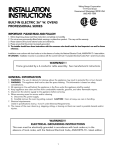
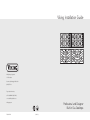
Viking Installation Guide
®
Viking Range Corporation
111 Front Street
Greenwood, Mississippi 38930 USA
(662) 455-1200
For product information,
call 1-888-VIKING1 (845-4641)
or visit the Viking Web site at
vikingrange.com
F20562D EN
Professional and Designer
Built-In Gas Cooktops
(121610)
Table of Contents
Warnings & Important Safety Instructions _______________________________________________3
Dimensions (VGSU Professional) _______________________________________________________6
Specifications (VGSU Professional) _____________________________________________________7
Dimensions (DGSU Designer) _________________________________________________________8
Specifications (DGSU Designer) _______________________________________________________9
Cutout Dimensions _________________________________________________________________10
Cutout Dimensions (VGSU Cooktop over Single Electric Oven)___________________________11
Cutout Dimensions (DGSU Cooktop over Single Electric Oven) __________________________12
Clearance Dimensions (Proximity to Cabinets)__________________________________________13
Clearance Dimensions (Wood/Composite Overlay) _____________________________________14
Electrical & Gas Requirements _______________________________________________________15
General Information ________________________________________________________________17
Installation _________________________________________________________________________18
Optional Gasket Installation ______________________________________________________18
Gas & Electrical Connection ______________________________________________________18
VGSU Bracket Installation ________________________________________________________19
DGSU Bracket Installation ________________________________________________________19
Final Preparation ___________________________________________________________________20
Performance Checklist ______________________________________________________________20
Service & Registration _______________________________________________________________21
IMPORTANT– Please Read and Follow
• Before beginning, please read these
instructions completely and carefully.
Your safety and the safety of others is
very important.
• DO NOT remove permanently affixed
labels, warnings, or plates from product.
This may void the warranty.
We have provided many important safety
messages in this manual and on your
appliance. ALWAYS read and obey all
safety messages.
This is the safety alert symbol. This
symbol alerts you to hazards that
can kill or hurt you and others.
• All local and national codes and
ordinances must be observed. Installation
must conform with local codes or in the
absence of codes, the National Fuel Gas
Code ANSI Z223.1 NFPA54-latest edition.
All safety messages will be preceded by
the safety alert symbol and the word
“DANGER,” “WARNING” or “CAUTION.”
These words mean:
• The installer must leave these instructions
with the consumer for local inspector’s use
and for future reference.
DANGER
Installation of any gas-fired equipment
should be made by a licensed plumber. A
manual gas shut-off valve must be installed
in the gas supply line ahead of the cooktop
in the gas stream for safety and ease of
service.
Hazards or unsafe practices
which WILL result in severe personal
injury or death
WARNING
In Canada: Installation must be in
accordance with the current CAN/CGA
B149.1 & 2 Gas Installation codes and/or
local codes. Electrical installation must be in
accordance with the current CSA C22.1
Canadian Electrical Codes Part 1 and/or
local codes.
Hazards or unsafe practices
which COULD result in severe personal
injury or death
CAUTION
Hazards or unsafe practices which
COULD result in minor personal injury
or property damage.
In Massachusetts: All gas products must be
installed by a “Massachusetts” licensed
plumber or gasfitter. A “T” type handle
manual valve must be installed in the gas
supply line to the appliance.
2
All safety messages will identify the
hazard, tell you how to reduce the chance
of injury, and tell you what can happen if
the instructions are not followed.
3
IMPORTANT– Please Read and Follow
DANGER
WARNING
FIRE/EXPLOSION
HAZARD
CHEMICAL HAZARD
If not installed, operated and
maintained in accordance
with the manufacturer’s
instructions, this product could expose
you to substances in fuel or from fuel
combustion which can cause death or
serious illness and which are known to
cause cancer, birth defects, or other
reproductive harm.
IF THE INFORMATION IN
THIS MANUAL IS NOT
FOLLOWED EXACTLY, A FIRE OR
EXPLOSION MAY RESULT CAUSING
PROPERTY DAMAGE, PERSONAL
INJURY, OR DEATH.
• DO NOT store or use gasoline or other
flammable vapors and liquids in the
vicinity of this or any other appliance.
• WHAT TO DO IF YOU SMELL GAS:
–DO NOT try to light any appliance.
–DO NOT touch any electrical switch.
–DO NOT use any phone in your
building.
–Immediately call your gas supplier
from a neighbor’s phone.
–Follow the gas supplier’s instructions.
–If you cannot reach your gas supplier,
call the fire department.
• Installation and service must be
performed by a qualified installer,
service agency, or the gas supplier.
For example, benzene is a chemical
which is part of the gas supplied to the
cooking product. It is consumed in the
flame during combustion. However
exposure to a small amount of benzene
is possible if a gas leak occurs.
Formaldehyde and soot are byproducts
of incomplete combustion. Properly
adjusted burners with a bluish rather
than yellow flame will minimize
incomplete combustion.
IMPORTANT– Please Read and Follow
WARNING
ELECTRICAL GROUNDING
INSTRUCTIONS
The cooktop must be electrically grounded
in accordance with local codes or, in the
absence of codes, with the ANSI/NFPA
No. 70-latest edition. Installation should
be made by a licensed electrician. This
appliance is equipped with a three-prong
grounding plug for your protection against
shock hazard and should be plugged
directly into a properly grounded
receptacle. DO NOT cut or remove the
grounding prong from the plug.
For personal safety, this appliance
must be properly grounded. DO NOT
under any circumstances cut or
remove the third (ground) prong from
the power plug.
CAUTION
Before placing the cooktop into operation,
always check for gas leaks with a soapy
water solution or other acceptable method.
DO NOT USE AN OPEN FLAME TO
CHECK FOR LEAKS.
CAUTION
BURN HAZARD
The use of cabinets for storage above the
appliance may result in a potential burn
hazard. Combustible items may ignite,
metallic items may become hot and
cause burns. If a cabinet storage is to be
provided the risk can be reduced by
installing a range hood that projects
horizontally a minimum of 5” (12.7 cm)
beyond the bottom of the cabinets.
WARNING
This appliance shall not be used for
space heating. This information is based
on safety considerations.
4
5
Dimensions
Specifications
(VGSU Professional)
30” Gas Cooktop
(VGSU Professional)
Professional Gas Cooktops
3
( 0-3
78 /4
.1
cm ”
)
Description
VGSU104
VGSU164
Overall width
30-3/4” (78.1 cm)
36-3/4” (93.3 cm)
Overall height from bottom
to top of grate
5” (12.7 cm)
Overall depth from rear
21” (53.3 cm)
Cutout width
”
21 cm)
3
.
(53
2-1/2” (6.4 cm)
Cutout depth
18-5/8” (47.3 cm) min. to
20-1/8” (51.1 cm)
To field convert from natural or LP/Propane, the orifice spuds and regulator
must be physically changed. Order conversion kit NK2VGSU to convert to
natural and LPK3VGSU to convert to LP. Uses standard residential
1/2” (1.3 cm) I.D. gas service line.
Electrical requirements
120 VAC/60 Hz; 4 ft. (121.9 cm), 3-wire cord with grounded
3-prong plug attached to product.
Maximum amp usage
2.0 amps
36” Gas Cooktop
Surface element rating
Left front
Left rear
cm
)
Center front/rear
Right front
Right rear
Approximate
shipping weight
16,000 Nat./15,500 LP (BTU)
(4.8 Nat./4.65 LP (kw))
12,000 Nat./11,500 LP (BTU)
(3.6 Nat./3.45 LP (kw))
N/A
6,000 Nat./5,500 LP (BTU)
(1.8 Nat./1.65 LP (kw))
8,000 Nat./7,500 LP (BTU)
(2.4 Nat./2.25 LP (kw))
16,000 Nat./15,500 LP (BTU)
(4.8 Nat./4.65 LP (kw))
12,000 Nat./11,500 LP (BTU)
(3.6 Nat./3.45 LP (kw))
12,000 Nat./11,500 LP (BTU)
(3.6 Nat./3.45 LP (kw))
6,000 Nat./5,500 LP (BTU)
(1.8 Nat./1.65 LP (kw))
8,000 Nat./7,500 LP (BTU)
(2.4 Nat./2.25 LP (kw))
67 lb. (30.2 kg)
80 lb. (36.0 kg)
”
21 cm)
.3
(53
6-19/32”
(16.7 cm)
2-1/2”
5”
(12.7 cm)
(6.4 cm)
1”
13/16”
Front view
(2.1 cm)
6
Right side view
34-3/8” (87.3 cm) min. to
35-7/8” (91.1 cm) max.
Cutout height
Gas requirements
36
(93-3/4
.3 ”
26-7/8” (68.3 cm) min. to
29-7/8” (75.9 cm) max.
(2.5 cm)
7
Dimensions
Specifications
(DGSU Designer)
30” Gas Cooktop
(DGSU Designer)
Designer Gas Cooktops
30
(78 -3/4
.1c ”
m)
Description
DGSU101
DGSU161
Overall width
30-3/4” (78.1 cm)
36-3/4” (93.3 cm)
Overall height from bottom
to top of grate
4-3/8” (11.1 cm)
Overall depth from rear
Cutout width
21” (53.3 cm)
29-1/8” (74.0 cm) min. to
29-7/8” (75.9 cm) max.
Cutout height
”
21 m)
.3
(53
3-1/8” (7.9 cm)
Cutout depth
c
Gas requirements
36” Gas Cooktop
36
19-3/4” (50.2 cm)
To field convert from natural or LP/Propane, the orifice spuds and regulator
must be physically changed. Order conversion kit DLPK to convert to LP. Uses
standard residential 1/2” (1.3 cm) I.D. gas service line.
Electrical requirements
120 VAC/60 Hz; 4 ft. (121.9 cm), 3-wire cord with grounded
3-prong plug attached to product.
Maximum amp usage
2.0 amps
Surface element rating
Left front
(93 -3/
.3 4 ”
cm
)
Left rear
Center
Right front
Right rear
Approximate
shipping weight
16,000 Nat./12,500 LP (BTU)
(4.1 Nat./4.0 LP (kw))
12,000 Nat./11,500 LP (BTU)
(3.5 Nat./2.8 LP (kw))
N/A
6,000 Nat./5,500 LP (BTU)
(1.8 Nat./LP (kw))
8,000 Nat./7,500 LP (BTU)
(2.1 Nat./LP (kw))
12,000 Nat./11,500 LP (BTU)
(3.5 Nat./2.8 LP (kw))
10,000 Nat./9,500 LP (BTU)
(2.9 Nat./LP (kw))
16,000 Nat./12,500 LP (BTU)
(4.1 Nat./4.0 LP (kw))
6,000 Nat./5,500 LP (BTU)
(1.8 Nat./LP (kw))
8,000 Nat./7,500 LP (BTU)
(2.1 Nat./LP (kw))
49 lb. (22.0 kg)
74 lb. (33.3 kg)
”
21.3)
(53
4-3/8”
(11.1 cm)
2-1/4”
(5.7 cm)
1-3/4”
Front view
8
34-7/8” (88.6 cm) min. to
35-7/8” (91.1 cm) max.
(4.5 cm)
9
Cutout Dimensions
Cutout Dimensions (VGSU Cooktop over Single Electric Oven)
” in.
/2 m
-1 )
2 cm
.4
(6
(4
B
”
/8 )
-5 cm
4
1 7.2
3
” (
/4 )
-1 cm
2
1 1.1
(3
(91”min
.4 .
cm
)
”
/8 )
-7 cm
36
6
2 3.3
(7
8” )
-5/.3 cm
8
1 7
28
(71-1/8
.4 ”
cm
)
14
-
A
(36 1/4”
.2 c
m) 14-1
(36 /4”
.2 c
m)
C
(12 5
.7 ”
(to cm) m
ek a
ick x.
)
28
(72-1/2
.4 ”
cm
)
30”W. Cooktop (VGSU104) over
30”W. Electric Oven (VESO130/530)
” in.
/2 m
-1 )
2 cm
.4
(6
(8
(
(4
”
/8 )
-7 cm
6
1 2.9
(91”min
.4 .
cm
)
”
/8 )
-3 cm
4
3 7.3
8” )
-5/ cm
1847.3
36
28
”
6 )
/1 m
-9 c
7 6
1 44.
(
(73-3/4
.0 ”
cm
)
1
(43 7”
.2 c
m)
VGSU104
VGSU164
DGSU101
DGSU161
A
26-7/8” (68.3 cm) min. to 34-3/8” (87.3 cm) min. to
29-7/8” (75.9 cm) max.
35-7/8” (91.1 cm) max.
A
29-1/8” (74.0 cm) min. to 34-7/8” (88.6 cm) min. to
29-7/8” (75.9 cm) max.
35-7/8” (91.1 cm) max.
B
18-5/8” (47.3 cm) min. to
20-1/8” (51.1 cm) max.
2-1/2” (6.4 cm)
B
19-3/4” (50.2 cm)
C
2-1/2” (6.4 cm)
C
Note: Based on 24” deep cabinet with 3/4” backsplash.
(12 5
.7 ”
(to cm) m
ek a
ick x.
)
1
(43 7”
.2 c
m)
3
(86 4”
.4
cm
)
36”W. Cooktop (VGSU164) over
36”W. Electric Oven (VESO166)
Note: Refer to the oven installation instructions for undercounter dimensions.
10
11
Cutout Dimensions (DGSU Cooktop over Single Electric Oven)
” in.
/2 m
-1 )
2 cm
.4
(6
36
Proximity to Side Cabinet Installation
A
B
28
C
(91”min
.4 .
cm
)
D
(71-1/8
.4 ”
cm
)
DGSU101
14
(36 1/4”
(12 5
.7 ”
cm
)m
A
.2 c
m) 14-1
(36 /4”
.2 c
m)
ax
.
Clearance Dimensions
B
C
D
28
(72-1/2
.4 ”
cm
)
29-1/8”
(74.0 cm)
19-3/4”
(50.2 cm)
14-3/4”
(37.4 cm)
14-3/4”
(37.4 cm)
30”W. Cooktop (DGSU101) over 30”W. Electric Oven (DSOE301/305)
Note: Refer to the oven installation instructions for undercounter dimensions. Installation will require an
elbow to be installed off of the regulator.
Minimum Clearances from Adjacent
Combustible Construction
• The cooktop may be installed directly to
existing base cabinets.
• The cooktop CANNOT be installed directly
adjacent to sidewalls, tall cabinets, tall
appliances, or other side vertical surfaces
above 36” (91.4 cm) high. There must be a
minimum of 8” (20.3 cm) side clearance from
the cooktop to such combustible surfaces
above the 36” (91.4 cm) counter height.
• Within the 8” (20.3 cm) side clearance to
combustible vertical surfaces above
36” (91.4 cm), the maximum wall cabinet
depth must be 13” (33.0 cm) and wall cabinets
within this 8” (20.3 cm) side clearance must be
18” (45.7 cm) above the 36” (91.4 cm) high
countertop.
• Wall cabinet above the cooktop must
be a minimum of 36” (91.4 cm) above the
countertop for a full width of the cooktop.
This minimum height requirement does not
apply if a rangehood is installed over the
cooking surface.
• A 120 volt wall receptacle should be
located approximately 6” (15.2 cm) below
the countertop cutout and 12” (30.5 cm)
from the right side of the cutout.
• Above countertop 36” (91.4 cm) minimum
• Side 8” (20.3 cm)
• Rear
o VGSU—2-1/2” (6.4 cm) min.
o DGSU— 2-1/2” (6.4 cm) min.
• Within 6” side clearance. Wall cabinets no
deeper than 13” (33.0 cm)
• Must be minimum 18” (45.7 cm) above
countertop
• Wall cabinets directly above the product must be
minimum 36” (91.4 cm) above the countertop
x.
mam)
”
3 c
1 3.0
(3
in.
(20
.3
c
”
8
(45
in.
” mcm)
6
3 4
.
(91
”m )
18 .7 cm
m
Downdraft Dimensions
m)
.
in
E
(Proximity to Cabinets)
F
D
C
VGSU104 VGSU164
34-7/8”
(88.6 cm)
28-1/16”
(71.3 cm)
B
20-5/8”
(52.3 cm)
20-5/8”
(52.3 cm)
18-3/4” 18-3/4”
(47.6 cm) (47.6 cm)
C
27
(68.6 cm)
33”
(84.0 cm)
27
33”
(68.6 cm) (84.0 cm)
B
D
2-1/4”
(5.7 cm)
2-1/4”
(5.7 cm)
3”
(7.6 cm)
3”
(7.6 cm)
E
1-1/16”
(1.1 cm)
15/16”
(1.0 cm)
N/A
N/A
F
1-1/16”
(2.7 cm)
15/16”
(1.0 cm)
1-1/16”
(2.7 cm)
1-1/4”
(3.2 cm)
A
34-1/4”
(87 cm)
A
VGSU
DGSU
2-1/2”
(6.4 cm)
2-1/2”
(6.4 cm)
in.
” mcm)
6
3 4
.
( 91
Note: Dimensions shown are for
use with combustible surfaces
unless otherwise stated.
Note: Refer to the downdraft installation instructions.
12
13
A
DGSU161
29-1/8”
(74.0 cm)
DGSU101
A
Clearance Dimensions
(Wood/Composite Overlay)
Electrical Requirements
The bottom of a standard hood should be
30” (76.2 cm) min. to 36” (91.4 cm) max.
above the countertop. This would typically
result in the bottom of the hood being
66” (167.6 cm) to 72” (182.9 cm) above the
floor. Refer to the rangehood installation
instructions for additional information. These
dimensions provide for safe and efficient
operation of the hood.
Wo
od
/Co
Ov mpo
erl sit
ay e
66
(16 ”mi
7.6 n.
c
to m)
72
(18 ”ma
2.9 x.
cm
)
Wo
od
/Co
Ov mpo
erl sit
ay e
66
(16 ”mi
7.6 n.
c
to m)
72
(18 ”ma
2.9 x.
cm
)
Electrical & Gas Requirements
”
24 m)
c
.0
(61 or
”
27 cm)
.6
8
(3
30
(76”min
.2 .
cm
36 to )
”
(91 ma
.4 x.
cm
)
Manual shut-off valve:
• The installer-supplied valve must be
installed in the gas service line ahead of
the appliance and regulator in the gas
stream and in a position where it can be
reached quickly in the event of an
emergency.
There is no connection necessary beyond
plugging the unit into a polarized,
grounded, 120 volt, 60 Hz, 15 amp circuit. A
minimum of 120VAC is required for proper
operation of gas ignition systems. DO NOT
use a GFI circuit. This circuit, however, MUST
be grounded and properly polarized. The
unit is equipped with 16-3 SPT2 power cord.
Note: If electrical power is not supplied or is
interrupted, the open top burners will have
to be lit manually with a match.
In Massachusetts: A “T” handle type
manual gas valve must be installed in
gas supply line to the appliance.
Pressure regulator:
• All heavy-duty, commercial-type cooking
equipment must have a pressure regulator
on the incoming service line for safe and
efficient operation, since service pressure
may fluctuate with local demand. The
regulator supplied with the cooktops must
be installed before any gas connections
are made.
Gas Connection
The gas supply (service) line must be the
same size or greater than the inlet line of the
appliance. All cooktops use a 1/2” (1.3 cm)
I.D. NPT (Sch40) inlet. Sealant on all pipe
joints must be resistive to LP/Propane gas.
These cooktops are designed specifically for
natural gas or liquid propane (LP) gas. It is
shipped from the factory adjusted for use
with natural or propane (LP) gas. Before
beginning installation verify that the model is
compatible with the intended gas supply.
”
30 cm)
.2
(76
6” m)
.2 c
5
(1
Wall Installation
30
(76”min
.2 .
cm
36 to )
”
(91 ma
.4 x.
c
m)
• Manifold pressure should be checked with
a manometer; natural gas requires 5.0”
WCP and LP/Propane requires 10.0” WCP.
Incoming line pressure upstream for the
regulator must be 1” WCP higher than the
manifold pressure in order to check the
regulator. The regulator used on this
cooktop can withstand a maximum input
pressure of 1/2 PSI (14.0” WCP). If
the line pressure is in excess of that
amount, a stepdown regulator will be
required.
IMPORTANT: Any conversion required
must be performed by a qualified licensed
plumber or gas service company. The
proper conversion kit must be ordered
from your authorized service agency or
dealer.
• The appliance must be disconnected from
the gas supply piping system during any
pressure testing of that system.
Island Installation
14
15
Electrical & Gas Requirements
Initial Ignition of Burners
Rigid Connections:
• Incoming gas is brought from an intake
pipe (not supplied) at the rear of the unit
to the pressure regulator; then to the
manifold pipe for distribution. The only
connection necessary is from the service
supply, through the shut-off valve (not
supplied), to this intake pipe (not
supplied) to the regulator supplied, but
not connected through the cooktop.
All cooktops are tested before leaving the
factory. Field adjustments may be necessary
for proper mixture of gas and air for proper
operation. When the cooktop is connected
to gas and electrical service, it should be
adjusted by a qualified technician. If it is not,
contact your dealer for the name of their
authorized service agency in your area.
Gas conversions and initial installation
adjustments are not the responsibility of the
manufacturer. To convert the VGSU model
to LP or natural gas, the orifice spuds and
regulator must be physically changed. The
proper conversion kit must be ordered from
your authorized service agency or dealer.
In Massachusetts: This appliance must be
installed with a 36” (3-foot) long flexible gas
connector.
CAUTION
Before placing the cooktop into operation,
always check for gas leaks with a soapy
water solution or other acceptable method.
DO NOT USE AN OPEN FLAME TO
CHECK FOR LEAKS.
Proper Lighting and Shutdown
Instructions
1. To ignite the surface burners, turn the
knob counter clockwise to any position.
2. Upon ignition of the surface burner, turn
the knob to the desired position, (HI,
Med, or Low).
3. To shutdown the burner, turn knob
clockwise to the OFF position.
4. In case of failure, shut the gas OFF using
the installer supplied manual shut-off
valve.
LP/Propane Conversion
The VGSU and DGSU models are field
convertible to LP/Propane gas or natural
gas. The orifice spuds and regulator must be
physically changed. For the VGSU/DGSU
models, order conversion kit NKPDC to
convert to natural and LPKPDC to convert to
LP/Propane. Gas conversions should be
completed by a qualified technician. Refer to
instructions in conversion kit for gas
conversions.
General Information
Electrical Requirement
CAUTION
Normal grounded household current,
120 volts, 60 Hz, 15 amps, single phase.
Electrical installation should comply with
national and local codes.
BURN HAZARD
The use of cabinets for storage above the
appliance may result in a potential burn
hazard. Combustible items may ignite,
metallic items may become hot and
cause burns. If a cabinet storage is to be
provided the risk can be reduced by
installing a range hood that projects
horizontally a minimum of 5” (12.7 cm)
beyond the bottom of the cabinets.
Air Supply and Ventilation
Means must be provided for any heavy-duty
cooking appliance to exhaust combustion
waste product to the outside of the building.
It is recommended that the cooktop be set
under a powered, vented exhaust hood, or
non-vented recirculating hood. Nothing
should obstruct the flow of combustion and
ventilation air.
WARNING
Gas Manifold Pressure
This appliance shall not be used for
space heating. This information is based
on safety considerations.
Natural gas – 5.0” W.C.P.
LP/Propane – 10.0” W.C.P.
Flexible Connections
If the unit is to be installed with flexible
couplings and/or quick disconnect fittings,
the installer must use a flexible connector of
at least 1/2” I.D. (1.3 cm) NPT with suitable
strain reliefs and comply with ANSI Z21.41
and Z21.69 standards.
• All openings in the wall behind the
appliance and in the floor under the
appliance shall be sealed.
• Keep appliance area clear and free from
combustible materials, gasoline, and other
flammable vapors.
• DO NOT obstruct the flow of combustion
and ventilation air.
• Disconnect the electrical supply to the
appliance before servicing.
When removing cooktop for cleaning and/or
service:
• Shut off gas at main supply
• Disconnect AC power supply
• Disconnect gas line to the inlet pipe.
• Lift appliance out of cabinet cutout.
16
17
Installation
VGSU Bracket Installation
1
2
Optional Gasket
1
2
1
1
2
2
Countertop
Cooktop
Countertop
Cooktop
2
2
Screw
Remove the grates and burner caps.
3
Turn the cooktop upside down and place on a nonscratch surface. Note: Make sure there are no loose
objects on the cooktop before turning upside down.
4
Optional Gasket
Peel away the plastic covering and place the gasket
material all the way around the burner flange.
IMPORTANT: Make sure the corners are covered
completely, leaving no air gaps.
Turn the cooktop over and place into countertop
opening.
Bracket
Eye Bolt
Bracket
Screw hold down brackets using the #10 x 1/2” sheet
metal screw to the burner box.
Screw the eye bolt into the self-retaining nut and
tighten firmly against bottom of countertop.
DGSU Bracket Installation
1
2
Countertop
Cooktop
Countertop
Cooktop
Bracket
Bracket
Place a bracket in the slots and lower
until the bracket catches.
Use the bolt to tighten the cooktop to the countertop.
Note: There must be a 1” (2.5 cm) clearance under
counter on all four sides of cooktop.
Gas & Electrical Connection
1
Note: Refer to
“Electrical & Gas
Requirements”
section for
proper
installation
information.
18
19
Final Installation
Service & Registration
1
Only authorized replacement parts may be used in performing service on the appliance.
All servicing should be referred to a qualified technician.
2
2
1
1
1
Contact Viking Range Corporation, 1-888-VIKING1 (845-4641), for the nearest service parts
distributor in your area or write to:
1
VIKING RANGE CORPORATION
PREFERRED SERVICE
1803 Hwy 82W
Greenwood, Mississippi 38930 USA
Replace the burner caps and grates.
Note: The narrow edge of grate goes toward center of unit.
The serial number and model number for your appliance can be found by looking under the
cooktop.
Final Preparation
• New units are cleaned at the factory
to remove any visible signs of dirt, oil,
grease, etc. remaining from the
manufacturing process. Some stainless
steel parts may have a plastic protective
wrapper which must be peeled off. The
cooktop should be washed thoroughly
with hot, soapy water and then rinsed and
wiped dry to remove these film residues
and any installation dust or debris before
being used for food preparation.
• All stainless steel body parts should be
wiped regularly with hot, soapy water
and with a liquid cleanser designed for
this material if build-up occurs. DO NOT
USE steel wool, abrasive cloths, cleansers,
or powders. If it is necessary to scrape
stainless steel to remove encrusted
material, soak with hot, wet cloths to
loosen the material, then use a wood
or nylon scraper. DO NOT USE a metal
knife, spatula, or any other metal tool
to scrape stainless steel. Scratches are
almost impossible to remove.
Record the following information indicated below. You will need it if service is ever required.
Model number ____________________________________________________________________________________
Serial number _____________________________________________________________________________________
Date of purchase __________________________________________________________________________________
Date installed ______________________________________________________________________________________
Dealer's name _____________________________________________________________________________________
Performance Checklist
Address ___________________________________________________________________________________________
These installation instructions should remain with the unit
for future reference.
A qualified installer should carry out the
following checks:
1-1/2”
(3.8 cm)
h Check top burner
ignition. The low
3/8”
flame should light at
(0.95
cm)
every port.
h Starting with the left
front burner, turn the corresponding knob
to the HI position – see drawing for
proper flame height.
h Repeat steps for other burners.
20
21
22
23