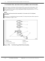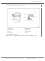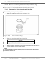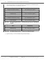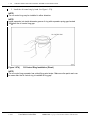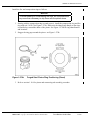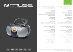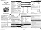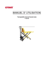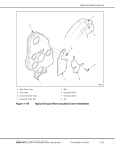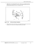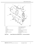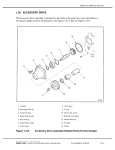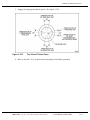
1
SERIES 60 SERVICE MANUAL
3. Stagger the ring gaps around the piston. See Figure 1-274.
Figure 1-274
Top View of Piston Dome
4. Refer to section 1.18.4 for piston and connecting rod assembly procedure.
All information subject to change without notice.
(Rev. 01/04)
6SE483 0303 Copyright © 2003 DETROIT DIESEL CORPORATION
From Bulletin 18–60–03Rev.
1-335
1.17A
FORGED STEEL ONE PIECE PISTON ASSEMBLY AND PISTON RING
1.17A FORGED STEEL ONE PIECE PISTON ASSEMBLY AND PISTON RING
Series 60 engines with Exhaust Gas Recirulation (EGR) systems built after December 1, 2003
will use a forged steel one piece piston assembly, incorporating the dome and skirt. The new
piston reduces friction, improves ring cooling and has a higher compression ratio of 17.25:1 for
12L and 16.75:1 for 14L.
NOTE:
The forged steel one piece piston assembly is to be used only for On-Highway
applications.
Ring grooves are machined into the piston assembly. The forged steel piston will not require the
use of bushings see Figure 1-274a.
1. Fire Ring
4. Retainer
2. Compression Ring
5. Piston Assembly
3. Oil Control Ring with Expander
6. Piston Pin
Figure 1-274a
One Piece Forged Steel Piston Assembly
(Rev. 01/04)
1-336
From Bulletin 18-60-03Rev.
All information subject to change without notice.
6SE483 0303 Copyright © 2003 DETROIT DIESEL CORPORATION
SERIES 60 SERVICE MANUAL
Each diesel piston is fitted with a fire ring, compression ring and one-piece oil control ring with
expander. See Figure 1-274b and see Figure 1-274c.
1. Oil Control Ring
5. Oil Ring Expander
2. Compression Ring*
6. Oil Control Ring
3. Fire Ring*
7. Compression Ring*
4. Piston Assembly
8. Fire Ring*
* Identification Mark to Face Top of Dome
Figure 1-274b
Forged Steel One Piece Piston Assembly Ring Location
All information subject to change without notice.
(Rev. 01/04)
6SE483 0303 Copyright © 2003 DETROIT DIESEL CORPORATION
From Bulletin 18-60-03Rev.
1-336a
1.17A
FORGED STEEL ONE PIECE PISTON ASSEMBLY AND PISTON RING
Figure 1-274c
Comparision of Piston Ring Packs
(Rev. 01/04)
1-336b
From Bulletin 18-60-03Rev.
All information subject to change without notice.
6SE483 0303 Copyright © 2003 DETROIT DIESEL CORPORATION
SERIES 60 SERVICE MANUAL
The fire and compression rings are installed with the “identification” mark facing up,
see Figure 1-274d.
Figure 1-274d
Fire and Compression Ring Identification
A one-piece oil control ring is used in the third groove. The expander is of Spira-Lox construction.
Figure 1-274e
Solid Core Piston Pin Cross Section
All information subject to change without notice.
(Rev. 01/04)
6SE483 0303 Copyright © 2003 DETROIT DIESEL CORPORATION
From Bulletin 18-60-03Rev.
1-336c
1.17A
FORGED STEEL ONE PIECE PISTON ASSEMBLY AND PISTON RING
The one piece forged steel piston assembly uses a floating piston pin which rides on the one piece
bushing pressed into the end of the connecting rod. The original closed end connecting rod and
solid core piston pin do not have drilled center orifices for lubrication. Oil for lubrication and
steel piston cooling is supplied by oil spray from piston cooling nozzles at the bottom of each
piston bore. For model year 2000 engines, an oil passage was incorporated into the connecting
rod design to improve lubrication to the piston pin.
(Rev. 01/04)
1-336d
From Bulletin 18-60-03Rev.
All information subject to change without notice.
6SE483 0303 Copyright © 2003 DETROIT DIESEL CORPORATION
SERIES 60 SERVICE MANUAL
1.17a.1
Repair or Replacement of Piston and Piston Ring
To determine if repair is possible or replacement is necessary, perform the following
procedure. See Figure 1-274f .
Figure 1-274f
Flowchart for Repair or Replacement of Piston and Piston Rings
All information subject to change without notice.
(Rev. 01/04)
6SE483 0303 Copyright © 2003 DETROIT DIESEL CORPORATION
From Bulletin 18-60-03Rev.
1-336e
1.17A
FORGED STEEL ONE PIECE PISTON ASSEMBLY AND PISTON RING
1.17a.2
Removal and Cleaning of Piston Assembly and Piston Ring
Refer to section 1.18.2 for piston and connecting rod assembly removal procedure.
1.17a.3
Disassembly of Piston Assembly and Piston Ring
Disassemble the piston and piston rings as follows:
1. Remove the piston rings with tool J 8128. See Figure 1-274g.
Figure 1-274g
Removal of Piston Rings
2. Remove oil control ring expander from oil control ring.
NOTICE:
The pin and piston assembly must be match-marked to assure
proper position and orientation.
3. Withdraw the piston pin and mark the front of the piston assembly with a paint pencil, so
it can be returned to the correct cylinder location.
NOTE:
The forged steel one piece piston assembly require the removal of the retainer before
withdrawing the piston pin.
(Rev. 01/04)
1-336f
From Bulletin 18-60-03Rev.
All information subject to change without notice.
6SE483 0303 Copyright © 2003 DETROIT DIESEL CORPORATION
SERIES 60 SERVICE MANUAL
1.17a.3.1
Inspection of Piston Assembly and Piston Rings
Clean the piston assembly and piston rings prior to inspection as follows:
NOTICE:
Do not attempt to clean the one piece forged steel piston by glass
beading. Glass beading will remove the surface treatment. Do
not refinish or polish the piston pin.
1. Clean the piston components with fuel oil.
To avoid injury from flying debris when using compressed
air, wear adequate eye protection (face shield or safety
goggles) and do not exceed 40 psi (276 kPa) air pressure.
2. Dry the piston components with compressed air.
3. If fuel oil does not remove the carbon deposits, use a chemical solvent that will not harm
the coating on the piston assembly. However if a chemical solvent is to be used for the
cleaning of the piston, remove the rings, some solvents can damage the top ring coating
material.
NOTICE
Do not glass bead the pin bushing or pin bore.
4. The piston assembly, including the compression ring grooves, is not tin-plated and may be
wire-brushed to remove any hard carbon.
5. Clean the ring grooves with a suitable tool or a piece of an old compression ring that
has been ground to a bevel edge.
6. Clean the inside surfaces of the piston dome and the oil relief channels in the oil ring
grooves.
Inspect the piston assembly and piston rings as follows:
1. Inspect the piston assembly.
[a]
Check the piston assembly for score marks, cracks, damaged ring grooves or
overheating indications.
[b]
If any of these indications are present, replace the piston assembly.
NOTE:
Burn spots may indicate an obstruction in the connecting rod oil passage.
2. Inspect the piston pin.
All information subject to change without notice.
(Rev. 01/04)
6SE483 0303 Copyright © 2003 DETROIT DIESEL CORPORATION
From Bulletin 18-60-03Rev.
1-336g
1.17A
FORGED STEEL ONE PIECE PISTON ASSEMBLY AND PISTON RING
[a]
Check the piston pin for fretting, cracking or signs of overheating.
[b]
If these are detected, replace piston pin.
[c]
Measure piston pin outside diameter. Specifications are listed in Table 1-20.
[d]
If the articulated steel piston pin is out of specification, replace with new part.
NOTICE:
If the piston pin used on forged steel one piece piston assemblies
is replaced for any reason, the piston assembly must also be
replaced.
3. Inspect the bushingless piston pin bore as follows.
[a]
Check the bushingless pin bores for scoring, pitting, flaking, cracking, excessive
wear or signs of overheating.
[b]
If these conditions are present the piston assembly must be replaced.
4. Inspect the edges of the piston assembly pin bore.
[a]
Check edges of the piston assembly pin bore for dents and dings.
[b]
If any are found it is acceptable to remove burrs at the pin bore edges by careful filing.
5. Inspect the connecting rod bushing.
[a]
Check the bushing for excessive fretting.
[b]
If excessive fretting is evident, replace the connecting rod assembly.
NOTE:
Remove any dirt or debris on the back of the piston pin bore that may take up clearance
required for piston pin installation.
6. If the piston pin used with a forged steel piston is replaced for any reason, the connecting
rod bushing must be inspected for wear before the rod is installed. If the bushing is worn
beyond limits, the connecting rod must be replaced. Specifications are listed in Table 1-23.
7. Check the cylinder liner for excessive out-of-round and high spots which could cause
failure of the piston. Specifications are listed in Table 1-16.
8. Check the block bore for excessive out-of-round, taper, and high spots that could cause
failure of the piston. Specifications are listed in Table 1-15.
(Rev. 01/04)
1-336h
From Bulletin 18-60-03Rev.
All information subject to change without notice.
6SE483 0303 Copyright © 2003 DETROIT DIESEL CORPORATION
SERIES 60 SERVICE MANUAL
1.17a.4
Assembly of Forged Steel Piston Assembly and Piston Rings
Prior to installing the piston rings, the ring gap of each piston ring must be measured.
1. Insert the piston rings inside of the cylinder liner one at a time, using a piston dome
(inserted upside down into the liner) to push the ring down. The piston dome should be
inserted into the liner, to the same depth as the ring being positioned.
2. For the oil control ring, insert the piston dome down into the liner, until the oil control ring
land is just into the liner. This will ensure that the rings are parallel with the top of the
liner, and that they are positioned in the liner within the normal area of ring travel.
3. After the three rings have been positioned in the liner, measure the ring gap of the top
ring with a feeler gage. See Figure 1-274h. Remove the ring from the liner after the
measurement is complete.
Figure 1-274h
Piston Ring Gap Measurement
All information subject to change without notice.
(Rev. 01/04)
6SE483 0303 Copyright © 2003 DETROIT DIESEL CORPORATION
From Bulletin 18-60-03Rev.
1-336i
1.17A
FORGED STEEL ONE PIECE PISTON ASSEMBLY AND PISTON RING
4. Repeat this procedure for each ring, and record your measurements. Allowable ring end
gaps are listed in Table 1-6a and listed in Table 1-6b.
Ring
Ring End Gap
Fire Ring (2.5 mm [0.098 in.] chrome)
0.50 - 0.85 mm (0.020 - 0.033 in.)
Fire Ring (3.0 mm [0.118 in.] HVOF)
0.55 - 0.85 mm (0.022 - 0.033 in.)
Fire Ring (3.5 mm [0.138 in.] plasma)
0.50 - 0.85 mm (0.020 - 0.033 in.)
Compression Ring
0.80 - 1.15 mm (0.031 - 0.045 in.)
Oil Control Ring
0.40 - 0.65 mm (0.016 - 0.026 in.)
14L Fire Ring: (3.0 mm [0.118 in.] chrome)
0.60 - 0.86 mm (0.024 - 0.034 in.)
14L Fire Ring: (3.0 mm [0.118 in.] HVOF)
0.55 - 0.85 mm (0.022 - 0.033 in.)
14L Compression Ring
0.63 - 0.98 mm (0.025 - 0.039 in.)
14L Oil Control Ring
0.21 - 0.51 mm (0.008 - 0.020 in.)
Table 1-6a
Allowable Ring End Gap — All Diesel (Except Pleasure Craft Marine)
Engines
Ring
Ring End Gap
12.7L Fire Ring: 3.0 mm (0.118 in.)
0.60 - 0.80 mm (0.024 - 0.031 in.)
Table 1-6b
Compression Ring
0.80 - 1.15 mm (0.031 - 0.045 in.)
Oil Control Ring
0.40 - 0.81 mm (0.016 - 0.032 in.)
Allowable Ring End Gap — Pleasure Craft Marine Engine
5. Refer to section 1.17a.5 for assembly of rings for diesel engines.
(Rev. 01/04)
1-336j
From Bulletin 18-60-03Rev.
All information subject to change without notice.
6SE483 0303 Copyright © 2003 DETROIT DIESEL CORPORATION
SERIES 60 SERVICE MANUAL
1.17a.5
Assembly of S60 Diesel Piston Rings
Assemble the piston rings as follows:
1. Install the ring expander in the oil control ring groove in the piston. See Figure 1-274i.
1. Oil Control Ring
3. Piston Assembly
2. Oil Control Ring Groove
4. Oil Control Ring Expander
Figure 1-274i
Forged Steel Piston Assembly Installation
All information subject to change without notice.
(Rev. 01/04)
6SE483 0303 Copyright © 2003 DETROIT DIESEL CORPORATION
From Bulletin 18-60-03Rev.
1-336k
1.17A
FORGED STEEL ONE PIECE PISTON ASSEMBLY AND PISTON RING
2. Install the oil control ring by hand. See Figure 1-274j.
NOTE:
The oil control ring may be installed in either direction.
NOTE:
Install expander into inside diameter groove of ring with expander spring gap located
180 from the oil control ring gap.
Figure 1-274j
Oil Control Ring Installation (Diesel)
NOTE:
The oil control ring expander has a identifying paint stripe. Make sure the paint mark can
be seen after the oil control ring is installed at ring gap.
(Rev. 01/04)
1-336l
From Bulletin 18-60-03Rev.
All information subject to change without notice.
6SE483 0303 Copyright © 2003 DETROIT DIESEL CORPORATION
SERIES 60 SERVICE MANUAL
Install the fire and compression rings as follows:
NOTICE:
To avoid breaking or overstressing the rings, do not spread them
any more than necessary to slip them over the piston dome.
1. Starting with the compression ring (second groove), install the compression ring and fire
ring with tool J 8128. See Figure 1-274k. Make sure the identifying dimple on the rings
is installed up, toward the dome of the piston. See Figure 1-274d for ring identification
and locations.
2. Stagger the ring gaps around the piston. see Figure 1-274k.
Figure 1-274k
Forged Steel Piston Ring Positioning (Diesel)
3. Refer to section 1.18.4 for piston and connecting rod assembly procedure.
All information subject to change without notice.
(Rev. 01/04)
6SE483 0303 Copyright © 2003 DETROIT DIESEL CORPORATION
From Bulletin 18-60-03Rev.
1-336m
1.18
PISTON AND CONNECTING ROD ASSEMBLY
1.18 PISTON AND CONNECTING ROD ASSEMBLY
Since the piston and connecting rod assembly is one unit made of two separate components, the
components will be addressed in separate sections.
For general piston information, refer to section 1.17.
For general connecting rod assembly information, refer to section 1.19. The 14L engine requires
that the piston, connecting rod, and cylinder liner be removed as an assembly.
NOTE:
Some 14L and steel cylinder kit procedures differ from the cast iron procedures.
Information regarding 14L and steel cylinder kits will follow cast iron procedures when
different.
(Rev. 01/04)
1-336n
From Bulletin 18-60-03Rev.
All information subject to change without notice.
6SE483 0303 Copyright © 2003 DETROIT DIESEL CORPORATION