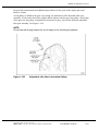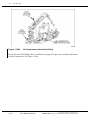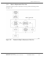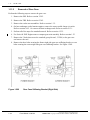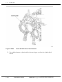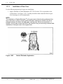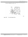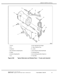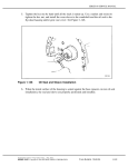
1
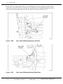
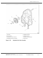
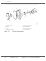
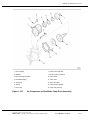
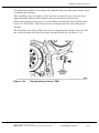
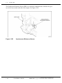
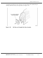
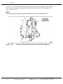
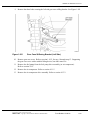
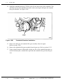
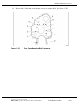
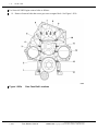
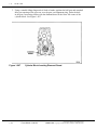
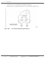
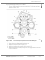
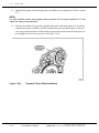
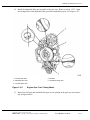
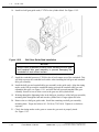
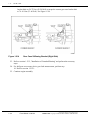
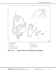
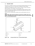
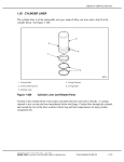
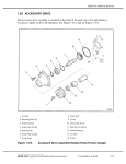
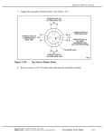
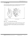
SERIES 60 SERVICE MANUAL
1.11 GEAR CASE
The gear case housing is constructed of cast iron, with machined mating surfaces, and is bolted to
the front of the engine cylinder block. The gear case and gear case cover are bolted together to
provide a sealed compartment for the engine gear train. See Figure 1-187.
1. Lifting Bracket
3. Gear Case Housing
2. Gear Case Cover
Figure 1-187
Gear Case and Gear Case Cover
Several components are mounted to the gear case, including the adjustable idler gear assembly,
see Figure 1-190, the fuel pump drive assembly, see Figure 1-191, the air compressor drive
assembly or raw water pump drive assembly, see Figure 1-192; the water pump assembly (1991
and later engines) see Figure 1-193; and the camshaft thrust plate and drive gear assembly
see Figure 1-210.
All information subject to change without notice.
6SE483 0204 Copyright © 2002 DETROIT DIESEL CORPORATION
From Bulletin 13-60-02
1-233
1.11
GEAR CASE
In July 2001, new right and left side gear case stiffening brackets were added to provide: reduce
engine noise, increase belt driven accessory life, reduce gear case vibration amplitude and reduce
wear on the cam thrust plate perimeter seal. See Figure 1-188 and see Figure 1-189 .
Figure 1-188
Gear Case Stiffening Bracket (Left Side)
Figure 1-189
Gear Case Stiffening Bracket (Right Side)
All information subject to change without notice.
1-234
From Bulletin 13-60-02
6SE483 0204 Copyright © 2002 DETROIT DIESEL CORPORATION
SERIES 60 SERVICE MANUAL
1. Gear Case
5. Adjustable Idler Gear
2. Diamond Dowel
6. Adjustable Idler Hub
3. Adjustable Idler Gear Locknut (3)
7. Adjustable Idler Gear Stud (3)
4. Adjustable Idler Gear Hub, Retainer
8. Round Dowel
Figure 1-190
Adjustable Idler Gear Assembly
All information subject to change without notice.
6SE483 0204 Copyright © 2002 DETROIT DIESEL CORPORATION
From Bulletin 13-60-02
1-235
1.11
GEAR CASE
1. Fuel Pump Drive Gear
5. Shaft and Bearing Assembly
2. Snap Ring
6. Fuel Pump Drive Hub
3. O-ring
7. Fuel Pump Drive Coupling
4. Fuel Pump Drive Housing
8. Fuel Pump Assembly
Figure 1-191
Fuel Pump Drive Assembly
All information subject to change without notice.
1-236
From Bulletin 13-60-02
6SE483 0204 Copyright © 2002 DETROIT DIESEL CORPORATION
SERIES 60 SERVICE MANUAL
1. Drive Housing
8. Drive Hub Flange Nut
2. Washers
9. Drive Housing Long Bolt
3. Drive Housing Short Bolt
10. Drive Shaft
4. Drive Ball Bearing
11. Drive Gear
5. Snap Ring
12. Drive Gear Bolt
6. Spacer
13. Drive Housing Gasket
7. Drive Hub
14. Gear Case Housing
Figure 1-192
Air Compressor or Raw Water Pump Drive Assembly
All information subject to change without notice.
6SE483 0204 Copyright © 2002 DETROIT DIESEL CORPORATION
From Bulletin 13-60-02
1-237
1.11
GEAR CASE
1. Retaining Bolt
11. Oil Seal
2. Washer
12. Water Pump Housing O-ring
3. Water Pump Drive Gear
13. Drain Cock
4. Snap-ring
14. Water Pump Housing
5. Bearing Race
15. Water Pump Housing Pipe Plug
6. Bearing
16. Water Seal
7. Spacer Rings (2)
17. Impeller
8. Bearing
18. Water Pump Cover O-ring
9. Bearing Race
19. Water Pump Cover
10. Drive Shaft
Figure 1-193
20. Water Pump Cover Snap Ring
Water Pump Assembly
All information subject to change without notice.
1-238
From Bulletin 13-60-02
6SE483 0204 Copyright © 2002 DETROIT DIESEL CORPORATION
SERIES 60 SERVICE MANUAL
To eliminate the possibility of oil leakage at the adjustable idler gear stud location, Detroit Diesel
recommends the following:
When rebuilding a Series 60 engine, or if the gear case is removed for any reason, the three
original adjustable idler gear studs should be removed and replaced with new studs.
Before pressing studs into the gear case, coat the shanks and underside of the stud heads with
Loctite® No. 242 Sealant. This will prevent any oil leakage around the studs during engine
operation.
The Timing Reference Sensor (TRS) is an electronic component that is bolted to the side of the
gear case on the intake (left) side of the engine just above the oil pan. See Figure 1-194.
Figure 1-194
Timing Reference Sensor (TRS)
All information subject to change without notice.
6SE483 0204 Copyright © 2002 DETROIT DIESEL CORPORATION
From Bulletin 13-60-02
1-239
1.11
GEAR CASE
The Synchronous Reference Sensor (SRS) is an electronic component that is bolted to the gear
case at the lower, intake (left) side of the engine. See Figure 1-195.
Figure 1-195
Synchronous Reference Sensor
All information subject to change without notice.
1-240
From Bulletin 13-60-02
6SE483 0204 Copyright © 2002 DETROIT DIESEL CORPORATION
SERIES 60 SERVICE MANUAL
An opening is provided in the center of the gear case, for the bull gear and camshaft idler gear
assembly, which bolts directly to the engine block. See Figure 1-196.
Figure 1-196
Bull Gear and Camshaft Idler Gear Assembly
All information subject to change without notice.
6SE483 0204 Copyright © 2002 DETROIT DIESEL CORPORATION
From Bulletin 13-60-02
1-241
1.11
GEAR CASE
An access cover is provided at the rear of the gear case on the cooler (right) side of the engine.
This access cover provides an opening for inspection of the accessory drive assembly drive
gear. See Figure 1-197.
NOTE:
This access cover opening may be cast closed on the rear of the gear case.
Figure 1-197
Accessory Drive Gear Access Cover (Pre-1991 Engines)
All information subject to change without notice.
1-242
From Bulletin 13-60-02
6SE483 0204 Copyright © 2002 DETROIT DIESEL CORPORATION
SERIES 60 SERVICE MANUAL
For gear lash measurement and adjustment procedures for the gears in the engine gear train,
Refer to section .
An oil gallery is drilled in the gear case casting, for lubrication of the adjustable idler gear
assembly. A hole in the front of the cylinder block, indexes with the gear case gallery. At the edge
of the gear case the gallery is threaded for insertion of a plug. An exit hole feeds the adjustable
idler gear assembly. See Figure 1-198.
NOTE:
Do not use the oil plug location for an oil supply or for checking oil pressure.
Figure 1-198
Adjustable Idler Gear Lubrication Gallery
All information subject to change without notice.
6SE483 0204 Copyright © 2002 DETROIT DIESEL CORPORATION
From Bulletin 13-60-02
1-243
1.11
GEAR CASE
Figure 1-198a
Air Compressor Lubrication Gallery
For the Series 60 2002 Engine there is a drilled oil passage in the gear case casting for lubrication
of the air compressor. See Figure 1-198a.
All information subject to change without notice.
1-243a
From Bulletin 13-60-02
6SE483 0204 Copyright © 2002 DETROIT DIESEL CORPORATION
SERIES 60 SERVICE MANUAL
1.11.1
Repair or Replacement of Gear Case
To determine if repair is possible or replacement is necessary, perform the following procedure.
See Figure 1-199.
Figure 1-199
Flowchart for Repair or Replacement of Gear Case
All information subject to change without notice.
6SE483 0204 Copyright © 2002 DETROIT DIESEL CORPORATION
From Bulletin 13-60-02
1-244
1.11
GEAR CASE
1.11.2
Removal of Gear Case
Perform the following steps to remove the gear case:
1. Remove the SRS. Refer to section 2.29.2 .
2. Remove the TRS. Refer to section 2.30.2 .
3. Remove the rocker arm assemblies. Refer to section 1.3.2.
4. On heat exchanger-cooled marine engines, remove the water-cooled charge air cooler.
Refer to section 4.4.2 . Or remove the heat exchanger tank. Refer to section 2.13.1 .
5. Perform all of the steps for camshaft removal. Refer to section 1.23.2.
6. For Series 60 2002 Engine remove compact gear train assembly. Refer to section 1.23.
7. Remove the 3 bolts that secure the camshaft gear pilot tool, J 35906, to the gear case
and remove the tool.
8. Remove the three bolts securing the former right side gear case stiffening bracket, or two
bolts securing the current right side gear case stiffening bracket. See Figure 1-200.
Figure 1-200
Gear Case Stiffening Bracket (Right Side)
All information subject to change without notice.
1-245
From Bulletin 13-60-02
6SE483 0204 Copyright © 2002 DETROIT DIESEL CORPORATION
SERIES 60 SERVICE MANUAL
9. Remove the three bolts securing the left side gear case stiffing bracket. See Figure 1-201
Figure 1-201
Gear Case Stiffening Bracket (Left Side)
10. Remove gear case cover. Refer to section 1.10.2, for step 1 through step 13. Supporting
the gear case cover with a suitable lifting device, but don't remove it.
11. Remove the fuel pump from the fuel pump drive assembly (or air compressor).
Refer to section 2.6.2 .
12. Remove the air compressor. Refer to section 10.1.5 .
13. Remove the air compressor drive assembly. Refer to section 10.3.2 .
All information subject to change without notice.
6SE483 0204 Copyright © 2002 DETROIT DIESEL CORPORATION
From Bulletin 13-60-02
1-246
1.11
GEAR CASE
14. Install the crankshaft protector, J 35994, to the oil seal contact area of the crankshaft. This
will help to protect the crankshaft seal surface when removing the bull gear and camshaft
idler gear assembly. See Figure 1-202.
Figure 1-202
Crankshaft Protector Installation
15. Remove the bull gear and camshaft idler gear assembly from the engine.
Refer to section 1.26.2.
16. Remove the adjustable idler gear assembly from the gear case. Refer to section 1.25.2.
17. Using a plastic hammer or fiber mallet, tap the rear face of the camshaft thrust plate to
remove the thrust plate, camshaft drive gear hub and camshaft drive gear from the gear
case.
All information subject to change without notice.
1-247
From Bulletin 13-60-02
6SE483 0204 Copyright © 2002 DETROIT DIESEL CORPORATION
SERIES 60 SERVICE MANUAL
18. Remove the 12 bolts that secure the gear case to the engine block. See Figure 1-203
Figure 1-203
Gear Case Mounting Bolt Locations
All information subject to change without notice.
6SE483 0204 Copyright © 2002 DETROIT DIESEL CORPORATION
From Bulletin 13-60-02
1-248
1.11
GEAR CASE
For Series 60 2002 Engine remove bolts as follows:
19. Remove fourteen bolts that secure gear case to engine block. See Figure 1-203a
Figure 1-203a
Gear Case Bolt Locations
All information subject to change without notice.
1-248a
From Bulletin 13-60-02
6SE483 0204 Copyright © 2002 DETROIT DIESEL CORPORATION
SERIES 60 SERVICE MANUAL
20. Using a leather or cloth-wrapped strap, support the gear case. See Figure 1-204. For
Series 60 2002 engines see Figure 1-204a
Figure 1-204
Gear Case Removal
All information subject to change without notice.
6SE483 0204 Copyright © 2002 DETROIT DIESEL CORPORATION
From Bulletin 13-60-02
1-249
1.11
GEAR CASE
Figure 1-204a
Series 60 2002 Gear Case Removal
21. Use a rubber hammer or plastic mallet to loosen the gear case from the cylinder block
dowels.
All information subject to change without notice.
1-249a
From Bulletin 13-60-02
6SE483 0204 Copyright © 2002 DETROIT DIESEL CORPORATION
SERIES 60 SERVICE MANUAL
1.11.2.1
Inspection of Gear Case
Clean all of the old gasket sealer from the mating surfaces of the gear case, gear case cover, and
engine block. Refer to "Gasket Eliminator® Removal," in the "General Information" section at the
beginning of this manual. Clean the gasket material from the mating surfaces of any components
or access covers that were removed from the gear case cover or gear case. Clean all of the parts
with clean fuel oil and dry with compressed air. Remove the oil gallery plug at the edge of the
gear case. See Figure 1-198.
To avoid injury from flying debris when using compressed
air, wear adequate eye protection (face shield or safety
goggles) and do not exceed 40 psi (276 kPa) air pressure.
Use compressed air to ensure the oil gallery is completely free of blockage. If necessary, use a
wire brush to clean the gear case oil gallery.
Inspect the gear case for stress cracks, breaks, or other damage. Repair or replace as necessary.
Inspect the adjustable idler gear studs for signs of galling or scoring. Replace as necessary.
Inspect all the individual components as outlined under the appropriate section.
All information subject to change without notice.
6SE483 0204 Copyright © 2002 DETROIT DIESEL CORPORATION
From Bulletin 13-60-02
1-250
1.11
GEAR CASE
1.11.3
Installation of Gear Case
Use the following instructions for gear case installation:
1. Apply a thin film of Gasket Eliminator® PT-7276 (Loctite® 518) or equivalent to the
cylinder block. See Figure 1-205. Carefully smooth the bead around the block-to-gear
case oil passage to avoid contamination.
NOTE:
The installation of Gasket Eliminator® to the gear case-to-block mating surfaces at the
top of the block is critical. Excess gasket eliminator material can extrude into the oil
passage between the block and gear case, causing early failure of components. In
addition, the bull gear recess area MUST be cleaned of any and all foreign material after
installation of the gear case to the engine block.
Figure 1-205
Gasket Eliminator Application
All information subject to change without notice.
1-251
From Bulletin 13-60-02
6SE483 0204 Copyright © 2002 DETROIT DIESEL CORPORATION
SERIES 60 SERVICE MANUAL
2. Insert gear case alignment plug, J 35651, into the bull gear and camshaft idler gear hub
recess in the cylinder block. See Figure 1-206.
Figure 1-206
Gear Case Alignment Plug
All information subject to change without notice.
6SE483 0204 Copyright © 2002 DETROIT DIESEL CORPORATION
From Bulletin 13-60-02
1-252
1.11
GEAR CASE
3. Using a suitable lifting sling made of cloth or leather, position the bull gear and camshaft
idler gear opening of the gear case over the gear case alignment plug. Index the hole
in the gear case mating surface with the diamond dowel at the lower left corner of the
cylinder block. See Figure 1-207.
Figure 1-207
Cylinder Block Locating Diamond Dowel
All information subject to change without notice.
1-253
From Bulletin 13-60-02
6SE483 0204 Copyright © 2002 DETROIT DIESEL CORPORATION
SERIES 60 SERVICE MANUAL
4. With the gear case alignment plug fully seated, the gear case centered on the alignment
plug and the diamond dowel in the cylinder block indexed with its mating hole in the gear
case, the gear case is positioned properly for bolt installation. See Figure 1-208.
Figure 1-208
Gear Case Positioning
NOTE:
Gasket Eliminator cures with the absence of air. The time between the installation of
the gear case, and torquing of the bolts that secure the gear case to the cylinder block
should be kept to a minimum.
All information subject to change without notice.
6SE483 0204 Copyright © 2002 DETROIT DIESEL CORPORATION
From Bulletin 13-60-02
1-254
1.11
GEAR CASE
5. Install the 12 gear case-to-cylinder block retaining bolts, finger-tight.
6. Torque the gear case-to-cylinder block bolts to 58-73 N·m (43-54 lb·ft). See Figure 1-209.
Figure 1-209
Gear Case Housing Bolt Torque Sequence
All information subject to change without notice.
1-255
From Bulletin 13-60-02
6SE483 0204 Copyright © 2002 DETROIT DIESEL CORPORATION
SERIES 60 SERVICE MANUAL
For Series 60 2002 Engine install gear case as follows:
7. There are 14 bolts that secure the gear case to engine block. For bolt torque and torque
sequence see Figure 1-209a.
Figure 1-209a
Gear Case Torque Sequence for Series 60 2002 Engine
8. Remove the gear case alignment plug from the gear case.
9. Install the air compressor. Refer to section 10.1.8.
10. Install the air compressor drive assembly. Refer to section 10.3.6 .
11. Install the fuel pump drive assembly to the gear case, if so equipped. Refer to section 2.6.5
or refer to section 2.6.6 .
All information subject to change without notice.
6SE483 0204 Copyright © 2002 DETROIT DIESEL CORPORATION
From Bulletin 13-60-02
1-255a
1.11
GEAR CASE
12. Install the fuel pump to the fuel pump drive assembly (or air compressor). Refer to section
2.7.3 .
NOTE:
For 1991 and later model year engines, refer to section 4.2.8 or refer to section 4.3.7 and
install the water pump assembly.
13. Lubricate the rubber O-ring on the camshaft thrust plate with clean engine oil. Install the
camshaft thrust plate assembly, with the camshaft drive gear and hub in place to the gear
case, using a plastic hammer or fiber mallet to tap the thrust plate rearward in the gear case
just enough to start it in the gear case. See Figure 1-210.
Figure 1-210
Camshaft Thrust Plate Installation
All information subject to change without notice.
1-256
From Bulletin 13-60-02
6SE483 0204 Copyright © 2002 DETROIT DIESEL CORPORATION
SERIES 60 SERVICE MANUAL
14. Install the adjustable idler gear assembly to the gear case. Refer to section 1.25.3. Align
the timing marks of the adjustable idler gear and camshaft drive gear. See Figure 1-211.
1. Camshaft Idler Gear
4. Bull Gear
2. Adjustable Idler Gear
5. Crankshaft Timing Gear
3. Camshaft Drive Gear
Figure 1-211
Engine Gear Train Timing Marks
15. Inspect the bull gear and camshaft idler gear access opening in the gear case and remove
any foreign material.
All information subject to change without notice.
6SE483 0204 Copyright © 2002 DETROIT DIESEL CORPORATION
From Bulletin 13-60-02
1-257
1.11
GEAR CASE
16. Install two bull gear guide studs, J 35785 to the cylinder block. See Figure 1-212.
Figure 1-212
Bull Gear Guide Stud Installation
NOTICE:
Always install crankshaft protector when installing the bull gear
and camshaft idler gear assembly to prevent damaging the
crankshaft oil seal contact surface.
17. Install the crankshaft protector, J 35994 to the oil seal contact area of the crankshaft. This
will help to protect the crankshaft seal surface when installing the bull gear and camshaft
idler gear assembly.
18. Install the bull gear and camshaft idler gear assembly to the guide studs. Align the timing
marks on the bull gear and the crankshaft timing gear and the camshaft idler gear and
adjustable idler gear; see Figure 1-211, and slide the bull gear and camshaft idler gear
assembly forward to seat it in the recess in the gear case and cylinder block.
19. Working through the lightening holes in the bull gear, install two of the bull gear assembly
mounting bolts through the hub and into the cylinder block. Finger-tighten the bolts.
20. Remove the two bull gear guide studs. Install the remaining two bull gear assembly
mounting bolts. Torque the bolts to 101-126 N·m (75-93 lb·ft). Tighten in a clockwise
sequence.
21. Check the timing marks on the gears to ensure the gear train is properly timed.
See Figure 1-211.
All information subject to change without notice.
1-258
From Bulletin 13-60-02
6SE483 0204 Copyright © 2002 DETROIT DIESEL CORPORATION
SERIES 60 SERVICE MANUAL
22. Perform the following:
[a]
For crankshaft timing gear-to-oil pump gear lash measurement. Perform step 2,
refer to section 1.21.2.1.
[b]
For crankshaft timing gear-to bull gear lash measurement. Perform step 3,
refer to section 1.21.2.1.
[c]
To install the gear case cover. Refer to section 1.10.3.
[d]
Install the two bolts and nuts securing the left side gear case stiffening bracket to the
gear case. Torque to 75–81 N·m (55–60) lb·ft). See Figure 1-213
Figure 1-213
Gear Case Stiffening Bracket (Left Side)
[e]
Install the bolt securing the left side gear case stiffening bracket to the cylinder head.
Torque to 58–73 N·m (43–54 lb·ft). See Figure 1-213
[f]
Install the bolt securing the right side gear case stiffening bracket to the gear case.
Torque the former bracket bolt to 58–73 N·m (43–54 lb·ft) or torque the current gear
case bracket bolt to 74–81 N·m (53–60 lb·ft). See Figure 1-214
NOTE:
Bolts attaching bracket to the gear case are torqued first, then the bolt to cylinder head is
torqued next.
[g]
Install the two bolts securing the former right side gear case stiffening bracket to the
cylinder head or one bolt securing the current right side bracket. Torque the former
All information subject to change without notice.
6SE483 0204 Copyright © 2002 DETROIT DIESEL CORPORATION
From Bulletin 13-60-02
1-259
1.11
GEAR CASE
bracket bolts to 58–73 N·m (43–54 lb·ft) or torque the current gear case bracket bolt
to 74–81 N·m (53–60 lb·ft). See Figure 1-214
Figure 1-214
Gear Case Stiffening Bracket (Right Side)
23. Refer to section 1.23.5, "Installation of Camshaft Bearing" and perform the necessary
steps.
24. For bull gear-to-accessory drive gear lash measurement, perform step
10. Refer to section 1.21.2.1.
25. Continue engine assembly.
All information subject to change without notice.
1-260
From Bulletin 13-60-02
6SE483 0204 Copyright © 2002 DETROIT DIESEL CORPORATION