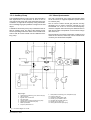
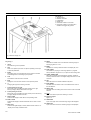
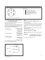
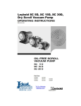
1
Vacuum Pumps
Instrumentation
Fittings and Valves
LEYBOLD VACUUM
GA 10.204 / 3.02
ULTRATEST UL 500
Helium Leak Detector
Cat. No.
155 85
Operating Instructions
LEYBOLD-Service
If an appliance is returned to LEYBOLD VACUUM
GmbH, indicate whether the appliance is free of substances damaging to health or whether it is contaminated. If it is contaminated also indicate the nature of the
hazard. LEYBOLD must return any appliance without a
declaration of contamination to the sender’s address.
General Note
The right of alterations in the design and the technical
data is reserved.
The illustrations are not binding.
Contents
1
1.1
1.1.1
1.1.2
1.1.3
1.1.4
1.2
1.2.1
1.2.2
1.3
1.3.1
1.3.2
1.3.3
1.3.4
1.3.5
1.3.5.1
1.3.5.2
1.3.5.3
1.3.6
1.3.6.1
1.3.6.2
1.3.6.3
1.3.6.4
1.3.6.5
1.3.6.6
1.3.6.7
1.4
1.4.1
1.4.2
Page
Description . . . . . . . . . . . . . . . . . . . . . . . . 4
General . . . . . . . . . . . . . . . . . . . . . . . . . . . 4
Unpacking . . . . . . . . . . . . . . . . . . . . . . . . . 4
Transport at the Customer’s Site . . . . . . . . . 4
Purpose . . . . . . . . . . . . . . . . . . . . . . . . . . . 4
Modules . . . . . . . . . . . . . . . . . . . . . . . . . . . 4
Technical Data . . . . . . . . . . . . . . . . . . . . . . 5
Physical Data . . . . . . . . . . . . . . . . . . . . . . . 5
Electrical Data . . . . . . . . . . . . . . . . . . . . . . 6
Technical Description . . . . . . . . . . . . . . . . . 6
Principle of Leak Detection . . . . . . . . . . . . . 6
Double-Entry Turbomolecular Pump . . . . . . 6
Forepump . . . . . . . . . . . . . . . . . . . . . . . . . . 6
Auxiliary Pump . . . . . . . . . . . . . . . . . . . . . . 7
Mass Spectrometer . . . . . . . . . . . . . . . . . . . 7
Ion Source . . . . . . . . . . . . . . . . . . . . . . . . . 8
Separation System . . . . . . . . . . . . . . . . . . . 8
Ion Collector . . . . . . . . . . . . . . . . . . . . . . . . 8
Electronics Modules . . . . . . . . . . . . . . . . . . 8
Electrometer Amplifier . . . . . . . . . . . . . . . . . 8
Mass Spectrometer Supply Unit . . . . . . . . . 8
Turbomolecular Pump Supply Unit . . . . . . . . 9
Power Distribution Unit . . . . . . . . . . . . . . . . 9
Power Conversion Unit . . . . . . . . . . . . . . . . 9
Control Unit . . . . . . . . . . . . . . . . . . . . . . . . 9
Keypad and Display Unit . . . . . . . . . . . . . . . 9
Equipment . . . . . . . . . . . . . . . . . . . . . . . . 10
Standard Specification . . . . . . . . . . . . . . . 10
Accessories . . . . . . . . . . . . . . . . . . . . . . . 10
2
2.1
2.1.1
2.1.2
2.1.2.1
2.2
2.2.1
2.2.2
Operation . . . . . . . . . . . . . . . . . . . . . . . . . 11
Installation of UL 500 . . . . . . . . . . . . . . . . 11
Layout of Controls and Displays . . . . . . . . 11
Preparations for Initial Startup . . . . . . . . . . 15
Electrical Connections . . . . . . . . . . . . . . . . 15
Description of Controls . . . . . . . . . . . . . . . 16
Power Switch . . . . . . . . . . . . . . . . . . . . . . 16
„SNIFF / VAC“ Key . . . . . . . . . . . . . . . . . . 16
2
2.2.2.1
2.2.2.2
2.2.3
2.2.3.1
2.2.3.2
2.2.4
2.2.4.1
2.2.4.2
2.2.5
2.2.5.1
2.2.5.2
2.2.6
2.2.7
2.2.8
2.2.9
2.2.10
2.2.10.1
2.2.10.2
2.2.11
2.2.12
2.2.13
2.2.14
2.2.15
2.2.16
2.2.17
2.2.18
2.2.18.1
2.2.18.2
2.2.18.3
2.2.19
2.2.20
2.2.21
Page
Vacuum Mode . . . . . . . . . . . . . . . . . . . . . . 16
„SNIFF“ Mode . . . . . . . . . . . . . . . . . . . . . . 16
„INSP / MEAS“ Key . . . . . . . . . . . . . . . . . . 17
„INSPECT“ Mode . . . . . . . . . . . . . . . . . . . 17
„MEASURE“ Mode . . . . . . . . . . . . . . . . . . 17
„START / RESET MAX“ Key . . . . . . . . . . . 17
„START / RESET MAX“ Key
in STANDBY . . . . . . . . . . . . . . . . . . . . . . . 17
„START / RESET MAX“ Key
in DETECT Mode . . . . . . . . . . . . . . . . . . . 17
„STOP/VENT“ Key . . . . . . . . . . . . . . . . . . 17
„STOP“ Function . . . . . . . . . . . . . . . . . . . . 17
„VENT“ Function . . . . . . . . . . . . . . . . . . . . 18
„ZERO“ Key . . . . . . . . . . . . . . . . . . . . . . . 18
„CAL“ Key . . . . . . . . . . . . . . . . . . . . . . . . . 18
„RATE / CONC“ Key . . . . . . . . . . . . . . . . . 18
„PREC“ Key . . . . . . . . . . . . . . . . . . . . . . . 19
„MAX / ACT“ Key . . . . . . . . . . . . . . . . . . . 19
„MAXIMUM“ Function . . . . . . . . . . . . . . . . 19
„ACTUAL“ Function . . . . . . . . . . . . . . . . . . 19
„FAST / SLOW“ Key . . . . . . . . . . . . . . . . . 19
„Numeric Keypad“ . . . . . . . . . . . . . . . . . . . 19
„Decimal Point“ Key ( . ) . . . . . . . . . . . . . . 19
„EXP“ Key . . . . . . . . . . . . . . . . . . . . . . . . . 19
„PLUS / MINUS“ Key (+/-) . . . . . . . . . . . . . 20
„Arrow LEFT / RIGHT“ Keys . . . . . . . . . . . 20
„CLR“ Key . . . . . . . . . . . . . . . . . . . . . . . . . 20
„LIMIT LOW / LIMIT HIGH“ Key . . . . . . . . . 20
Operation with only „LIMIT LOW“
Activated . . . . . . . . . . . . . . . . . . . . . . . . . . 20
Operation with „LIMIT LOW“
and „LIMIT HIGH“ Activated . . . . . . . . . . . 20
Manual Ranging in Connection
with set Upper and Lower Limit . . . . . . . . . 21
„OPT“ Key . . . . . . . . . . . . . . . . . . . . . . . . . 21
„HELP“ Key . . . . . . . . . . . . . . . . . . . . . . . . 24
„EXEC“ Key . . . . . . . . . . . . . . . . . . . . . . . 24
GA 10.204/3.02 - 08/96
2.2.22
2.2.23
2.2.24
2.2.25
2.3
2.3.1
2.3.1.1
2.3.2
2.3.2.1
2.3.2.2
2.3.3
2.3.4
2.3.4.1
2.3.5
2.3.6
2.4
2.5
2.5.1
2.5.1.1
2.5.1.2
2.5.2
2.5.2.1
2.5.2.2
2.5.2.3
2.5.3
2.5.4
2.6
2.7
2.7.1
Page
Volume Control . . . . . . . . . . . . . . . . . . . . . 24
Recorder Output and Remote Control
Connection Socket . . . . . . . . . . . . . . . . . . 25
Pin-out of the Multifunction Socket . . . . . . 26
Headset Output . . . . . . . . . . . . . . . . . . . . . 26
Description of Displays . . . . . . . . . . . . . . . 27
Analog Display . . . . . . . . . . . . . . . . . . . . . 27
Analog Display in Conjunction
with „LIMIT LOW / LIMIT HIGH“ Functions 27
Digital Display . . . . . . . . . . . . . . . . . . . . . . 27
Digital Display in Conjunction
with „ACTUAL“ Function . . . . . . . . . . . . . . 27
Digital Display in Conjunction
with „MAXIMUM“ Function . . . . . . . . . . . . . 28
Limit Value Display (Low and
High Limits) . . . . . . . . . . . . . . . . . . . . . . . . 28
Status Displays . . . . . . . . . . . . . . . . . . . . . 28
Description of Status Displays . . . . . . . . . . 28
Alphanumeric Display . . . . . . . . . . . . . . . . 29
Acoustic Signal . . . . . . . . . . . . . . . . . . . . . 29
Startup (First Pumpdown Cycle) . . . . . . . . 30
Operating Modes . . . . . . . . . . . . . . . . . . . 31
Vacuum Mode ( VAC) . . . . . . . . . . . . . . . . 31
Local Leak Detection in the
Vacuum Mode . . . . . . . . . . . . . . . . . . . . . . 31
Integral Leak Detection in the
Vacuum Mode . . . . . . . . . . . . . . . . . . . . . . 32
„SNIFF“ Mode . . . . . . . . . . . . . . . . . . . . . . 33
Local Leak Detection in SNIFF Mode . . . . 33
Integral Leak Detection in SNIFF Mode . . . 33
Calculation of Standard Leak Rate as
a Function of Pressure Differential . . . . . . . 34
„INSPECT“ Mode . . . . . . . . . . . . . . . . . . . 34
„MEASURE“ Mode . . . . . . . . . . . . . . . . . . 34
Shutdown . . . . . . . . . . . . . . . . . . . . . . . . . 35
Calibration . . . . . . . . . . . . . . . . . . . . . . . . 35
Calibration in Vacuum Mode . . . . . . . . . . . 35
GA 10.204/3.02 - 08/96
Page
2.7.1.1 Calibration with Internal
Calibrated Leak . . . . . . . . . . . . . . . . . . . . . 35
2.7.1.2 Calibration with External
Calibrated Leak . . . . . . . . . . . . . . . . . . . . . 35
2.7.2
Calibration in SNIFF mode . . . . . . . . . . . . 36
2.7.2.1 Calibration with a Known
Helium Concentration . . . . . . . . . . . . . . . . 36
2.7.2.2 Calibration of Helium Leak Rate . . . . . . . . 36
2.8
Automatic Functions . . . . . . . . . . . . . . . . . 37
2.8.1
AUTOTUNE . . . . . . . . . . . . . . . . . . . . . . . 37
2.8.2
AUTOZERO . . . . . . . . . . . . . . . . . . . . . . . 37
2.8.3
AUTORANGE . . . . . . . . . . . . . . . . . . . . . . 37
3
3.1
3.2
3.3
3.4
3.5
Maintenance . . . . . . . . . . . . . . . . . . . . . . 39
Checking the Oil Level and Gas Ballast
Switch of the Auxiliary Pump or Forepump 39
Exchanging the Fluorescent
Tube behind the Display . . . . . . . . . . . . . . 39
Changing the Fuses on the
Power Distribution (LV) Front Panel . . . . . . 39
Exchanging the Filter Mat . . . . . . . . . . . . . 40
Draining Condensate from the
Compressor Buffer Vessel . . . . . . . . . . . . 41
ANNEX 1 . . . . . . . . . . . . . . . . . . . . . . . . . . . . . . . . 42
Parameter entry mode (PARA MODE) . . . . . . . . . . . 42
ANNEX 2 . . . . . . . . . . . . . . . . . . . . . . . . . . . . . . . . 43
Operation of the UL 500 on mass 2 and 3
(Hydrogen) . . . . . . . . . . . . . . . . . . . . . . . . . . . . . . . 43
ANNEX 3 . . . . . . . . . . . . . . . . . . . . . . . . . . . . . . . . 44
Equipment messages; Messages for
the operator on the text display . . . . . . . . . . . . . . . . 44
ANNEX 4 . . . . . . . . . . . . . . . . . . . . . . . . . . . . . . . . 46
Error messages . . . . . . . . . . . . . . . . . . . . . . . . . . . 46
3
1 Description
1.1 General
These Operating Instructions contain important information on the functions, installation,
operation, troubleshooting and maintenance
of the ULTRATEST UL 500.
Before startup of the detector, please read Sections 1.1
and 1.4. For initial startup, follow Sections 2.1 and 2.4 to
2.6.
Important remarks concerning operational safety and
protection are emphasized as follows:
Warning
Indicates procedures that must be strictly observed to prevent hazards to persons.
Caution
Indicates procedures that must be strictly observed to prevent damage to, or
destruction of, the ULTRATEST UL 500
helium leak detector.
Note
Indicates special technical requirements that the user
must comply with.
The references to diagrams, e.g. (2/5), consist of the Fig.
No. and the Item No. in that order.
1.1.2 Transport at the Customer’s Site
For transport of the instrument pull or push it only at the
housing and not at the display unit.
Special preparations are required for transportation of
the UL 500 with a crane.
The set of crane eyes Ref. No. Nr. 200 59 475 contains
an extended crane eye to prevent damage to the display
unit through the steel wire. Further parts are included for
stiffening of the frame:
Clamping pieces
to prevent the dislodging of the crane eyes from the
aluminium profile.
Screws
to stiffen the bottom plate. From serial No. 018700090
and higher, the use of these screws it is not required.
Moreover it is recommended to use a transport frame so
that the lifting forces are applied perpendiculary to the
work panel of the UL 500 and the profiles of the UL 500
are subjected only to pulling forces.
Caution
The exclusive use of standard crane
eyes will result in damage to the display
unit. The additional strengthening measures using the clamping pieces and
screws must be introduced to prevent
damage to the instrument.
1.1.1 Unpacking
1.1.3 Purpose
Unpack the helium leak detector immediately after delivery, even if it is to be put into operation at a later date.
The ULTRATEST UL 500 helium leak detector is a helium leak indicator based on the mass-spectrometric principle of detection. It permits leak tests to be carried out
on test objects of virtually all sizes and up to the largest
volumes.
Caution
Pull or push the instrument only at its
housing and not at its display unit.
Examine the shipping container for any external damage
and then completely remove the packaging materials.
Note
The shipping container and packaging materials must be
kept in the event of complaints about damage.
Check that the ULTRATEST UL 500 is complete (Section
1.4) and carefully examine it visually.
Examine the display unit to ensure that no damage has
occurred during shipment.
If any damage is discovered, report it immediately to the
forwarding agent and insurer.
If the damaged part has to be replaced, please get in
touch with the orders department.
4
All equipment needed for leak detection is supplied with
the UL 500.
1.1.4 Modules
The UL 500 comprises three main assemblies (see
Fig.1) :
Operating level
- keypad (1/1)
- display unit (1/2)
- work panel (1/3)
Measurement and control level
- valve block (1/4)
- compressed air supply (1/5)
- high-vacuum plug-in (1/9)
- electronics plug-in (1/10)
GA 10.204/3.02 - 08/96
Pump level
- backing pump (1/6)
- auxiliary pump (1/7)
- mains transformer (1(8)
- peripheral connections
Response times
up to test-object volumes of 10 l
up to test-object volumes of 50 l
permissible temperature range
1.2 Technical Data
Safety
The instrument meets the specifications of protection
class 1 according to VDE 0411 (IEC 348).
Max. measurable helium leak rate
Max. indicatable helium leak rate
(qualitative measurement)
Display capabilities for leak rate:
Quasi-analog display for leak rate:
360 ° circular indicator, with logarithmic scale,
1 decade per revolution,
45 segments correspond to 5 %
resolution of indicated value
Bar scale for leak rate exponent
exponent display from -10 to +3
Digital display for leak rate
Units displayed
1.2.1 Physical Data
10 mbar·l·s-1
103 mbar·l·s-1
≤1s
≤5s
10 to 40 °C
2 digits,
2-digit exponent, sign
ppm
mbar·l·s-1
Atm·cc·sec-1 (US unit)
Pa·m3·s-1
<1s
Note
The measurement units displayed can only be changed
in a special operating mode of the instrument (PARA
MODE). Refer to Annex 1.
100 mbar
1000 mbar
Two „limit“ displays to indicate the low and high range
limits.
Max. total gas flow at inlet with limit of detection
2·10-10 mbar·l·s-1
0.1 mbar·l·s-1
-9
-1
1·10 mbar·l·s
0.5 mbar·l·s-1
-5
-1
5·10 mbar·l·s
400 mbar·l·s-1
Display capabilities for status
Light spots for display status
MAX / ACT
storage of max. value
FAST / SLOW
smoothing of measured value
BACKGRND
suppression of zero
Light spots for leak detection status
PREC
sensitivity
VAC / SNIFF
operating mode
STOP / VENT
status of test object
CAL
calibration
CAT2
cathode 2
Min. measurable leak rate
2·10-10 mbar·l·s-1
with time constant
Max. inlet pressure
for quantitative measurement
for qualitative measurement
≤ 5 min
Time until ready to display
Detectable masses
2, 3, 4 amu
Pumpdown times until ready for leak detection
without additional volume
with test-object volume 1 l
with test-object volume 50 l
6s
6s
150 s
Key to Fig. 1
1 Keypad
2 Display unit
3 Work panel
4 Valve block
5 Compressed air supply
6 Forepump
7 Auxiliary pump
8 Mains transformer
9 High vacuum plug-in
10 Electronics plug-in
Fig. 1 Modules
GA 10.204/3.02 - 08/96
5
Noise when running
max. 58 dBA
Dimensions (H x W x D)
1.3.1 Principle of Leak Detection
Weight
(with auxiliary pump TRIVAC D 25 B)
205 kg
Cat.No.
155 85
1.2.2 Electrical Data
Mains voltage, convertible
100 V, 110 V, 127 V ± 5 %
200 V, 208 V, 220 V, 240 V, 380 V ± 5 %
Mains frequency
50/60 Hz
Nominal power
PN = 2.2 kW
Max. turn-on power
PS = 5.5 kW
Mains connection for QUICKTEST
Caution
220 V a.c.
This connection always carries 220 V
a.c. independently of the mains voltage.
Recorder output
For recorder with an
internal resistance of min. 2.5 kΩ
1.Leak rate, linear
1.0 - 9.9 V per decade
Leak rate exponent
0.5 V per decade
beginning with 1 V at 10-10 mbar·l·s-1
2.Leak rate, logarithmic
3.Inlet pressure and fore
pressure, logarithmic
Headset output
internal resistance of headset
output power
1.3 Technical Description
110.5 x 62.7 x 77.5 cm
0.5 V per decade
beginning with 1 V at
10-10 mbar·l·s-1
0.5 V per decade
beginning with 1 V
at 10-3 mbar
min. 8 Ω,
max. 500 mW
The UL 500 operates on the counterflow principle, i.e.
helium diffuses against the turbomolecular pump’s direction of flow into the mass spectrometer, while heavy
gases, especially water vapours, are held back (massdependent compression capacity).
A cold trap in conjunction with liquid nitrogen is thus not
needed.
A special feature of the UL 500 is the double-entry turbomolecular pump, whose inlet side at the test object
ensures short response times. Furthermore, as a result
the inlet of the UL 500 is not constantly linked to a forepump, hence preventing test objects from becoming contaminated with hydrocarbons.
The UL 500 thus achieves pumping and response times
which are shorter than for the full-flow technique involving liquid nitrogen, without any appreciable reduction of
sensitivity.
1.3.2 Double-Entry Turbomolecular Pump
The double-entry turbomolecular pump of the UL 500
combines in a single housing two turbomolecular pumps
driven by a common motor.
The two turbomolecular pumps pump in opposite directions into a common forepressure connection.
One side of the turbomolecuIar pump (compression
side) produces from the helium pressure in the foreline
the helium pressure that is detected in the mass spectrometer. The pump’s stable compression capacity for
helium is exploited for this purpose. This capacity,
together with the pumping capacity of the forepump,
determines the sensitivity of the system.
The other side of the turbo pump (pump side) serves as
a high-vacuum pump to evacuate the inlet resp. the test
object.
The double-entry turbomolecular pump is a special
pump for the UL 500; its designation is TURBOVAC 150.
1.3.3 Forepump
The forepump produces a proportional helium pressure
from the helium flow entering the UL 500. The stable helium pumping capacity of the pump is exploited for this
purpose. This capacity, together with the compression of
one stage of the turbomolecular pump, determines the
sensitivity of the system. A TRIVAC D 4 B rotary-vane
vacuum pump is integrated in the UL 500 as forepump.
All data of the forepump are contained in the Operating
Instructions GA 01.201.
6
GA 10.204/3.02 - 08/96
1.3.4 Auxiliary Pump
1.3.5 Mass Spectrometer
The integrated auxiliary pump in the UL 500 evacuates a
test object down to the pressure at which it can be
connected to the pump side of the turbomolecular pump.
In addition, it supports the forepump during leak detection in handling large gas quantities coming from the test
object.
The main components of the mass spectrometer (MS)
are an ion source, a magnetic separation system and an
ion collector (3/5).
A TRIVAC D 25 B rotary-vane pump is installed in the UL
500 as auxiliary pump. For data of the auxiliary pump,
see the Operating Instructions GA 01.202. Instead a TRIVAC D 16 B, D 40 B or D 65 B can be installed as auxiliary pump.
Key to Fig. 2
1 Total-pressure measuring point, at the inlet (P1)
2 Test connection
3 Bypass valve of inlet valve
4 Inlet valve (VE)
5 Venting valve for turbomolecular pump (VF2)
6 Double-entry turbomolecular pump
7 Mass spectrometer
8 Forepump TRIVAC D 4 B
The ion source ionizes neutral gas particles, thereby
generating an ion beam. Positively charged ions are
accelerated out of the ion source and subsequently
reach the magnetic field. There they are deflected into an
orbit whose radius is dependent on the mass-to-charge
ratio of the ions.
Only the helium ions meet the separation conditions and
reach the ion collector, where they can be measured as
current by the electrometer amplifier.
9
10
11
12
13
14
15
Total-pressure measuring point, forepressure (P2)
Coupling valve (VK)
Throttle for massive leak mode
Auxiliary pump TRIVAC D 25 B
Test leak with test-leak valve (VT)
Auxiliary-pump valve (VH)
Venting valve for test object (VF1)
Fig. 2 Functional diagram of UL 500
GA 10.204/3.02 - 08/96
7
1.3.5.1 Ion Source
Electrons with 80 eV energy are used in the ion source.
The electrons emerging from the hot cathode (3/1) are
attracted by the positive anode (3/2). However, they do
not immediately reach the anode (3/2), but oscillate to
and fro for several times until finally reaching the wire
spiral of the anode (3/2).
In this way the electrons ionize gas atoms through
impact. These ions are extracted from the ion source by
an extractor screen (3/10) connected to ground and
enter the magnetic separation system.
The anode is heated during run-up to prevent polymerized hydrocarbon deposits (insulating layers that may
impair the sensitivity).
After run-up the anode is no longer heated as the operating temperature of the ion source (cathode heating) is
sufficient.
The cathodes (3/1) and (3/3) consist of iridium tape coated with thorium oxide. Owing to this thorium coating, the
iridium filaments operate at a much lower temperature
than tungsten ones and possess excellent resistance
(burnout resistance) to embrittlement, oxygen, water
vapour and hydrocarbons.
Caution
Halogens or halogen-containing substances may adversely affect the service
life of the cathodes.
The intermediate screen (3/9) ensures additional separation of unwanted ions of other gases.
1.3.5.3 Ion Collector
The ion collector (3/5) consists of a suppressor and its
proper collector.
The suppressor has a positive potential slightly below
the anode potential. It is designed to prevent scattered
ions with a lower energy than required from reaching the
collector. Resolution at low detection rates is thus improved.
The collector collects the incoming ions and neutralizes
them. The corresponding current reaches the subsequent amplifier.
1.3.6 Electronics Modules
See Fig. 4.
1.3.6.1 Electrometer Amplifier
The electrometer amplifier amplifies the current generated at the ion collector of the mass spectrometer. Its gain
can be changed in three stages. Changeover and processing of the analog output voltage are accomplished
by the control unit. The detection limit in the most sensitive range is approx. 4·10-15 A.
1.3.5.2 Separation System
A magnetic sector field (3/8) with 180° deflection is used
as separation system. Owing to the inhomogenity of the
magnetic field vertically in relation to the ion beam, additional concentration is achieved in this direction (Z-focussing), resulting in a high sensitivity.
1.3.6.2 Mass Spectrometer Supply Unit
This unit generates all voltages and currents needed for
operating the mass spectrometer:
- Anode heating voltage
- Cathode heating voltage
Key to Fig. 3
1 Cathode 1
2 Anode
3 Cathode 2
4 Amplifier
5 Ion collector
6 Shield for ion collector
7 Suppressor
8 Magnetic field
9 Intermediate screen
10 Extractor screen
11 Shield ring
Fig. 3 Schematic representation of the mass spectrometer
8
GA 10.204/3.02 - 08/96
1.3.6.6 Control Unit
- Anode voltage
- Suppressor voltage
Malfunctions in the mass spectrometer are detected and
communicated to the control unit. The latter monitors the
mass spectrometer supply unit.
1.3.6.3 Turbomolecular Pump Supply Unit
This unit controls and monitors the turbomolecular
pump. It is in turn monitored by the control unit, which
thus controls the pump.
1.3.6.4 Power Distribution Unit
All circuits needed for operating and monitoring the
rotary-vane pumps and valves are contained in the
power distribution unit. This unit is in turn controlled by
the control unit.
The control unit is the central component of the leak
detector’s electronics system. It controls and monitors all
other modules. Its microprocessor is thus constantly
informed of the status of the entire leak detector and can
act accordingly. The control unit is linked to the operation
and display unit so as to receive operator commands
and to output measured values and messages.
1.3.6.7 Keypad and Display Unit
This unit serves the purpose of communication with the
operator. It receives commands entered at the keypad
and outputs measured values and messages via the display.
Like the control unit, this unit possesses a microprocessor. The two processors are in constant mutual contact
for the purpose of exchanging commands and measured
values.
1.3.6.5 Power Conversion Unit
This unit generates from the AC supplied via the mains
transformer all the DC supply voltages needed for operating the electronics units.
Mass Spectrometer
Vacuum System
Mains
Power distribution unit
Power conversion
unit
•
Turbomolecular
pump supply unit
•
Control unit
Display unit
Mass spectrometer
supply unit
Electrometer
amplfier
•
Microprocessor
Microprocessor
Keypad
Fig. 4 Block diagram
GA 10.204/3.02 - 08/96
9
1.4 Equipment
1.4.1 Standard Specification
The ULTRATEST UL 500 helium leak detector is delivered ready for use.
- UL 500 with built-in display unit and with power cord
attached
- Set of gaskets
- Set of tools in bag
- Set of fuses
- Folder with operating instructions:
Rotary-vane vacuum pump
TRIVAC D 4 B = GA 01.201
Rotary-vane vacuum pump
TRIVAC D 25 B = GA 01.202
Spare parts list = ET 10.204
- 6-way plug for the recorder output, Ref. No. 500 17 119
- centering ring with grid insert for the inlet flange,
Ref. No. 411 70 121
1.4.2 Accessories
Calibrated leak TL 9
Cat.No. / Ref. No.
155 81
Calibrated leak TL 8
165 57
Calibrated leak TL 6
155 66
Calibrated TL 4
155 65
Calibrated TL 4 - 6
155 80
Reducer DN 40/16
183 89
Helium spray gun with 5 m hose
165 55
Standard sniffer
155 90
Helium sniffer Quicktest
155 78
Headset
165 07
Interface V.24 / RS 232 C
156 05
Trigger outputs
156 06
Set of crane eyes
200 59 475
Solenoid gas ballast valves with air inlet
200 59 643
Antistatic work plate
200 59 665
Exhaust filter
200 59 658
Air filtering mat for the rear
200 59 736
Remote control
upon request
Air inlet for venting valve
upon request
10
GA 10.204/3.02 - 08/96
2
Operation
2.1 Installation of UL 500
When moving the UL 500 pull or push it only at its housing and not at the display.
When lifting the UL 500 with a crane, special preparations are required. See Section 1.1.2.
Moreover it is recommended to use a transport frame so
that the lifting forces are applied perpendiculary to the
work panel of the UL 500 and the profiles of the UL 500
are subjected only to pulling forces.
Caution
The exclusive use of standard crane
eyes will result in damage to the display
unit. The additional strengthening measures using the clamping pieces and
screws must be introduced to prevent
damage to the instrument.
2.1.1 Layout of Controls and Displays
Note
- Fig. 7 shows a list of the operating elements on the operating unit.
- Fig. 8 shows a list of the display elements on the display unit.
An overview of the controls on the top and front of the UL
500 is given in Fig. 5.
Caution
The mains socket (5/6) for the QUICKTEST always carries 220V a.c!
In addition to the above controls (see Fig. 5) at the top
and front of the UL 500, the headset connection (6/2),
the loudspeaker (6/3), the loudspeaker volume control
(6/1), the recorder connection socket (6/5) and the V.24 /
RS 232 C interface connection socket (6/6)
Key to Fig. 5
1 ON/OFF power switch
2 START/STOP key
3 Operating unit
4 Display unit
5 Connection flange for test objects
6 Mains socket for QUICKTEST
Caution
The mains socket for the QUICKTEST always carries 220V a.c!
Fig. 5 Controls of UL 500
GA 10.204/3.02 - 08/96
11
Key to Fig. 6
1 Volume control
2 Headset connection
3 Loudspeaker
4 Display unit
5 Connection socket for a recorder
6 Connection socket for V.24 / RS 232 C
interface and trigger relay options
Fig. 6 Back of display unit
Key to Fig. 7
1
HELP
Not used during normal operation.
2
OPT
Start of an optional input / start or optional operating mode. Input
of optional parameters.
3
EXEC
Termination of an input and execution of the relevant command.
Acknowledgement of a message by the operator.
12 PREC
Switches the release of the most sensitive measuring range for
autoranging either on or off.
13 ZERO
Transfers the currently measured value to the display as „zero“.
14 STOP / VENT
Terminates the pumping or measuring operation in progress.
When pressed for longer than 2 s, it opens the inlet venting valve.
4
CLR
Cancellation of the last function entered.
15 START / RESET MAX
Starts the pumpdown and measurement operation. Transfer of
currently measured value to the digital display and search for next
maximum.
5
EXP
Setting the cursor to enter numbers in the exponent panels.
16 CAL
Starts the internal or external calibration sequence.
6
+/Changing the sign when entering a number.
7
Arrow pointing to the right
Moving the cursor (indicating the input position) to the right.
Moving a lengthy display text further to the right.
17 INSP / MEAS
Activates either the search mode or the measurement mode of
the leak detector.
8
9
Arrow pointing to the left
Moving the cursor (indicating the input position) to the left. Moving
a lengthy display text back to the left.
19 Point
Input of the decimal point when entering a number.
FAST / SLOW
Switches the display to either fast or slow operating mode.
20 Numeric keypad
Digits 0...9
10 RATE / CONC
Switches the display to indicate either leak rate or helium concentration.
11 MAX / ACT
Switches the digital display to either „Retain the last maximum“ or
„Display the currently measured value“.
12
18 SNIFF / VAC
Activates either the sniffing mode or the vacuum mode of the leak
detector.
21 LIMIT HIGH
Input of the upper limit of the measuring range to be displayed.
22 LIMIT LOW
Input of the lower limit of the measuring range to be displayed.
GA 10.204/3.02 - 08/96
Fig. 7 Operating unit
GA 10.204/3.02 - 08/96
13
Key to Fig. 8
1 Circular quasi-analog display of the leak rate in the „Inspect“
and „Measure“ modes. One revolution corresponds to one
decade of the measuring range. Quasi-analog display of a
measurement interval defined with the LIMIT values.
2 Exponent scale
For quasi-analog display of leak rate.
3 Digital display of the measured value as leak rate or concentration in the „MEASURE“ mode with mantissa and exponent.
4 Unit „ppm“ for „Concentration“ mode.
5 Units for „Rate“ mode.
6 MAX / ACT
Indicates the current operating status of the digital display.
7 FAST / SLOW
Indicates the current speed of overall display reaction.
8 CAT 2
Informs the operator that the second cathode of the ion source
has been put into service.
9 STOP / VENT
Indicates the current operating status of the leak detector.
10 SNIFF / VAC
Indicates the current operating mode of the leak detector.
11 PREC
Indicates that the PRECISION measuring range for AUTORANGING has been released.
12 BACKGRND
Indicates that zero has been shifted for the displayed measured value.
13 CAL
Indicates that the operator should perform calibration.
14 Digital display for indicating and entering the high limit of a
restricted measurement interval.
15 Marks for LIMIT LOW and LIMIT HIGH on the display in the
interval measurement mode.
16 Digital display for indicating and entering the low limit of a
restricted measurement interval.
17 Alphanumeric display line to show messages for the operator and to check the input of parameters by the operator.
Fig. 8 Display unit
14
GA 10.204/3.02 - 08/96
Key to Fig. 9
1 Rear panel of UL 500
2 Terminal strip
3 Plug-in jumpers
4 Transparent plastic plate
5 Mains cord
6 Exhaust D 4 B
7 Exhaust D 25 B
8 Connection of air supply option
9 Label giving the set mains voltage (on plastic
panel)
10 Label giving the electrical data
11 Plate with serial number
Fig. 9 Mains connection, name plates and exhaust connections
2.1.2 Preparations for Initial Startup
The UL 500 is delivered ready for use. The integrated
rotary-vane pumps are filled with oil. The mains connection has to be matched to the existing mains voltage (see
Section 2.1.2.1).
Caution
When operating the UL 500 in rooms
and especially when leaktesting largevolume test objects or when operating
the gas ballast, the exhaust connections
(9/6) and (9/7) must be lead to the outside via suitable hoses.
As an alternative exhaust filters may be mounted (see
Section 1.4.2).
In rooms with helium concentrations significantly above
5 ppm the use of air supply lines is recommended. In
such cases helium-free air should be fed via a line to the
venting valve (VF 1; 2/15). Special accessories are available for this purpose upon request.
Note
- Prior to initial startup, check the oil level of the auxiliary
pump and forepump (see Section 3.1).
- Before connecting the UL 500 to the mains, check
whether the mains voltage matches the voltage required (see Section 2.1.2.1).
2.1.2.1 Electrical Connections
Note
In general, the currently valid VDE 0100 regulations must
be observed.
The transformer integrated in the UL 500 permits an universal adaptation to mains voltages used throughout the
world, see Section 1.2.2. This is achieved by inserting
several plug-in jumpers (9/3) into a terminal strip (9/2).
The required position depending on the local mains voltage is given in Fig. 10.
A connection diagram for the different mains voltages
according to Fig. 10 is also given inside the UL 500 on its
rear panel.
Fig. 10 Jumpers on the terminal strip for adaptation to different mains voltages
GA 10.204/3.02 - 08/96
15
The mains voltage is adapted on terminal strip (9/2) at
the rear of the UL 500 above the inlet for the power supply cord (9/5) and behind a transparent plastic plate
(9/4). The factory set mains voltage is shown on the information label (9/9) mounted there.
Caution
The equipment voltage printed on the
information label must correspond to the
available mains voltage.
2.2 Description of Controls
Note
- Fig. 7 shows a list of the operating elements on the operating unit.
- Fig. 8 shows a list of the display elements on the display unit.
The UL 500 is designed for maximum simplicity and clarity of operation. Hence most of the control operations
that can be executed via the keys, are supported by displays. Apart from the information in the following, descriptions of the individual key functions, the meanings of
the displays are explained in Section 2.3. Also refer to:
- the list of operating elements see Fig. 7
- the list of display elements see Fig. 8
- SNIFF or VAC
- RATE or CONC
- PREC on or off
- Status of the alphanumerical display (display P 1, P 2)
- Status of the recorder output
(Output of P 1, P 2; leak rate linear or logarithmic)
- Status of the V.24 / RS 232 C option
- Status of the trigger option
- Equipment-specific parameters, programmed in the
PARA MODE (see Annex 1)
- Factors from OPT CALEMV
- Anode voltage (value determined through AUTOTUNE)
2.2.2 „SNIFF / VAC“ Key
SNIFF Note
The SNIFF / VAC key (7/18) may only be
VAC actuated in the STANDBY mode.
The „SNIFF / VAC“ key (7/18) is employed to select the
basic operating modes SNIFF and VAC.
Changeover between SNIFF and VAC necessitates a
few changes in the control sequence of the UL 500. The
changeover is not carried out until acknowledged by
pressing the „EXEC“ key (7/3). The operator receives the
necessary information via the alphanumeric display line
(8/17) and via the display „SNIFF“ and „VAC“ (8/10). The
display of the mode still valid is lit, that of the mode which
can be selected flashes at the same time.
2.2.1 Power Switch
The entire leak detector is switched on by actuating the
power switch.
The UL 500 first conducts a selftest of individual modules. If concluded with no faults, the pumps are switched
on. After the turbomolecular pump has been run up
(approx. 4 min), the UL 500 is ready to operate.
The UL 500 employs the alphanumeric display (8/17) to
inform the operator of all automatically executed actions
(see Section 2.4).
Note
During the selftest the turbopump valve VF2 is briefly
actuated for testing purposes.
After completion of run-up the UL 500 is set automatically to the operating condition at the time it was switched off. All required parameters for this are stored in a
battery-backed-up memory.
(The life of the battery is 6 years approx.)
The following parameters are stored when switching off:
- LIMIT LOW value
- LIMIT HIGH value
- LIMIT LOW ON / OFF
- LIMIT HIGH ON / OFF
- INSP or MEAS
16
2.2.2.1 Vacuum Mode
In this operating mode, leak detection can be conducted
with the basic UL 500 unit.
The test object is evacuated with the integrated pumps of
the UL 500 and sprayed with helium from the outside to
localize leaks (also see Section 2.5). The mode is indicated by the display VAC (8/10) lighting up. The indicated
measured values are always leak rates; it is possible for
the display to indicate either of the following units (8/4) or
(8/5):
mbar·l·s-1,
Atm·cc·sec-1 (USA unit)
Pa·m3·s-1
These units are default units of the UL 500 and they can
only be changed in a special operating mode (PARA
MODE, see Annex 1).
2.2.2.2 SNIF Mode
In this operating mode, the UL 500 is normally operated
with an external sniffer unit. This mode is indicated in the
SNIFF display panel (8/10). It is possible to indicate the
measured values as a helium concentration (ppm) or as
a leak rate (mbar·l·s-1) or as the unit which can only be
GA 10.204/3.02 - 08/96
changed in the PARA MODE. The RATE/CONC (7/10)
key is used for the switchover.
2.2.3 „INSP / MEAS“ Key
The INSP / MEAS key (7/17) can be pressed
to choose between the INSPECT mode and
the MEASURE mode. The major difference
between them is the measurement accuracy.
INSP
MEAS
The measured values appear on the display in the following fashion:
- The circular display (8/1) in conjunction with the exponential scale (8/2) shows the current leak rate.
- The digital display (8/3) appears only in the MEASURE
mode (7/17). Its function still depends on the type of
display selected via MAX / ACT (7/11).
The message „DETECTING INSPECT“ or „DETECTING
MEASURE“ appears on the alphanumeric display (8/17)
if no special function of this display has been selected by
pressing the „OPT“ key (7/2).
2.2.3.1 „INSPECT“ Mode
Starting from the MEASURE mode, the INSPECT mode
is activated by pressing the „INSP / MEAS“ key (7/17)
and acknowledging the function with the „EXEC“ key
(7/3).
The INSPECT mode gives the operator a quick overview
of existing leaks and their location, without a quantitative
display of a precise measured value. The representation
is only via the quasi-analog display (8/1) and (8/2). The
digital display (8/3) is deactivated in this operating mode,
thus eliminating the possibility of switching over from
„Retain the last maximum“ (MAX) to „Display the currently measured value“ (ACT) (see Section 2.2.10). It is
not possible to calibrate the UL 500 in the INSPECT
mode (see also Sections 2.2.7 and 2.7). The PRECISION function (7/12) cannot be selected.
2.2.4.2 „START / RESET MAX“ Key in
DETECT Mode
Starting from the DETECT mode already initiated, i.e.
after having already pressed the „START“ key once, and
with display type „Retain the last maximum“ (MAX)
(7/11) activated, the RESET MAX function is executed
every time the key is pressed.
From the point of actuation onward, all current leak rate
values are displayed which are higher than a preceeding
one. The next max. value is sought and stored in the display.
Note
If the ACT display type (display the currently measured
value) is activated, pressing the „RESET MAX“ key is
ineffectual.
2.2.3.2 MEASURE Mode
Starting from the INSPECT mode, the MEASURE mode
is activated by pressing the INSP/MEAS key (7/17) and
acknowledging the function with the „EXEC“ key (7/13).
The MEASURE mode is employed for quantitative determination of a leak. The measured leak rate is indicated
both on the quasi-analog display (8/1) and (8/2) and on
the digital display (8/3).
If possible, the UL 500 should be calibrated before operating it in the MEASURE mode (also see Sections 2.2.7
and 2.7).
2.2.4 „START / RESET MAX“ Key
START The „START / RESET MAX“ key (7/15)
RESET MAX assumes either of two functions depending on the main status of the UL 500.
2.2.4.1 „START / RESET MAX“ Key in STANDBY
Starting from the STANDBY mode of the UL 500, evacuation of a test object connected is initiated by pressing
the „START“ key. The UL 500 operates with automatic
measuring range selection, the AUTORANGING (see
Section 2.8.3).
GA 10.204/3.02 - 08/96
2.2.5 „STOP / VENT“ Key
The „STOP / VENT „key (7/14) has either of
STOP two functions depending on how long it is
VENT pressed.
2.2.5.1 „STOP“Function
Starting from the DETECT mode of the UL 500, evacuation of the test object is interrupted by pressing the
„STOP“ key (7/14). To do so, the key must be pressed for
less than 1.1 s. The unit switches to the STANDBY mode,
i.e. all valves are closed.
Next a correction of the internal Zero level is carried out
for the ranges FINE 3 and PREC. For this the coupling
valve VK is opened briefly and then shut. At the same
time the last internal leak rate signal is displayed which
was determined as the offset after the last Zero determination in the two measurement ranges.
This takes approximately 10 s.
After Zero correction the detection limit is displayed.
The operator is informed of the status by the „STOP“ display (8/9) lighting up. In addition, the message
„STANDBY FOR MEASURE“ or
17
„STANDBY FOR INSPECT“ appears in the alphanumeric display line (8/17) if no special function of the display
has been selected by pressing the OPT key (7/2).
Note
If the UL 500 is already in the STANDBY mode, pressing
the STOP key again will let the UL 500 determine the
background.
2.2.5.2 „VENT“ Function
The VENT function is achieved only if the „STOP / VENT“
key (7/14) is held down for more than 1.1 s. After this
period the inlet vent valve VF1 (2/15) is opened. The
VENT indicator (8/9) lights up to report this operating
mode. The valve VF1 can be closed again by:
- Briefly pressing the „STOP / VENT“ key again. The
UL 500 then enters the STANDBY mode.
- Pressing the „START / RESET MAX“ key. The UL 500
then enters the DETECT mode.
2.2.6 „ZERO“ Key
A constant leak rate display can be suppres-
ZERO sed by means of the ZERO function such as
for example a constant helium background of a test sample.
The Zero function is only active in the DETECT mode,
i.e. it is not possible to suppress internal backgrounds of
the UL 500 itself. This is done by pressing the „STOP“
key. See Section 2.2.5.1. Pressing the „ZERO“ key (7/13)
initiates storage of the current leak rate as „Zero“ without
changing the internal Zero.
Only values above this Zero are displayed, resulting in
enhanced resolution of the displayed measurement signal.
If measured values occur that are below the stored zeropoint, an automatically floating zero-adaptation initiates
storage of these negative leak rates as new zero points.
To draw the operator’s attention to the suppressed background, the red warning indicator BACKGROUND (8/12)
lights up. The enhanced resolution is limited by the measurement accuracy of the UL 500.
The zero, set through the ZERO function is derived from
the actual measured value by:
- Setting the meas.-value mantissa to 0.0.
- Shifting the measured-value exponent by one decade.
Example:
Measured value 7.4·10-3 after pressing the „ZERO“ key:
Display 0.0·10-4 Exceptions:
- Normal AUTORANGING: At leak rates under 1.0·10-8
mbar·l·s-1 the exponent is not switched over any more.
- AUTORANGING with PRECISION: At leak rates under
2.0·10-9 mbar·l·s-1 the exponent is not switched over
any more.
18
The ZERO function is deactivated by pressing the ZERO
key again.
The ZERO function is automatically deactivated if the
STOP / VENT key (7/14) is actuated.
Note
The Zero function acts only upon the display and not the
recorder output.
2.2.7 „CAL“ Key
CAL
Internal or external calibration is initiated by
pressing the „CAL“ key (7/16). The UL 500
controls all subsequent steps automatically.
The UL 500 discerns automatically between internal calibrated leak and external calibrated leak which is connected to the inlet flange, depending on the operating mode
at the point of entering the CAL command:
- Pressing the „CAL“ key (7/16) in the DETECTING
mode: external calibration
- Pressing the „CAL“ key (7/16) in the STANDBY mode:
Internal calibration
If an external calibration is to be performed the calibrated leak has to be connected to the inlet flange beforehand.
After pressing the „CAL“ key it is still possible to switch
over between internal and external calibration by pressing „START“ (7/15) and „STOP“ (7/14).
The sequence varies depending on the operating mode
of the UL 500 (also see Section 2.7.2).
Note
- After actuating the „CAL“ key (7/16), the initiation of
calibration must additionally be acknowledged by pressing the „EXEC“ key (7/3).
- This initiation and the running process can be terminated by pressing the „CLR“ key (7/4).
2.2.8 „RATE / CONC“ Key
RATE
CONC
The „RATE / CONC“ key (7/10) is used to
change the measured value presentation
from RATE to CONC, and vice versa. It is
effectual only in the SNIFF mode of the
UL 500.
RATE The measured value is displayed as leak rate in
the unit selected (8/5).
CONC The helium concentration is shown in ppm (8/4).
GA 10.204/3.02 - 08/96
2.2.9 „PREC“ Key
Pressing the „PREC“ key (7/12) influences
PREC the meas. range of the UL 500 during AUTO-
RANGING, i.e. with this key the release of the
most sensitive measuring range is activated or deactivated.
The measuring range attainable by AUTORANGING normally ends at a leak rate of approx. 1·10 -9 mbar·l·s-1.
After pressing the „PREC“ key (7/12), maximum sensitivity is released for the detection of a leak rate of
2·10-10 mbar·l·s-1.
This release must be acknowledged by actuating the
„EXEC“ key (7/3). The request for the operator to do so
appears in the alphanumeric display line (8/17), while the
PREC indicator (8/11) flashes.
This function can be cleared by operating the „CLR“ key
(7/4).
The PRECISION function is indicated by the PREC display (8/11) staying lit.
Note
The PRECISION function is only possible in the MEASURE mode (7/17).
Leak rates under 1·10-9 mbar·l·s-1 can not be measured
until the test object’s pressure is sufficiently low, which is
reached in the course of evacuation. This is noticeable
especially when large volumes are involved.
circular display (8/1) and the exponential scale (8/2) are
not affected. They always show the currently measured
value.
Pressing the „START / RESET MAX“ key (7/15) clears
the max. value being displayed, and the currently measured value appears. The next measurement cycle
begins, with the max. measured value again being stored
on the digital display.
Pressing the STOP/VENT key (7/14) clears the MAXIMUM function.
2.2.10.2 „ACTUAL“ Function
With this type of display the currently measured value is
always indicated on the digital display (8/3) and on the
quasi-analog display (8/1) and (8/2).
2.2.11 „FAST / SLOW“ Key
The FAST / SLOW key (7/9) switches over
the speed of the measured-value display.
FAST results in the display reacting quickly;
with SLOW an unsettled measured-value
reading is damped to a greater degree.
FAST
SLOW
Note
The FAST function should be selected when wanting to
localize leaks.
The function is deactivated by pressing the PREC key
(7/12) again and acknowledging via the EXEC key (7/3).
The function changes whenever this key is pressed. The
function just selected is shown on the display (8/7).
2.2.10 „MAX / ACT“ Key
2.2.12 Numeric Keypad
MAX
ACT
The MAX / ACT key (7/11) can be used to
seIect two functions:
- Retain the last maximum (MAX)
- Display the currently measured value
(ACT)
Starting from the function just set, the function changes
every time the key is pressed and this is visually represented on the MAX and ACT indicators (8/6).
The functions can only be selected in the MEASURE
and DETECTING modes.
123
456
789
0
2.2.13 Decimal Point Key ( . )
.
The key has no function in the INSPECT mode.
2.2.10.1 „MAXIMUM“ Function
Pressing the „MAX / ACT“ key (7/11) to obtain the function „Retain the last maximum“ has the result that only
the maximum measured value which has occurred up to
this point is shown in the digital display (8/3). The analog
GA 10.204/3.02 - 08/96
The numbers 0 to 9 (7/20) are employed to
enter parameters required to operate the
UL 500.
The decimal point key (7/19) is used in combination with the numeric keypad (7/20) to
enter digits.
2.2.14 „EXP“ Key
The „EXP“ key (7/5) is used when entering
numbers. The possible input point (cursor)
immediately jumps to the first digit of the
exponent when the key is pressed.
EXP
19
2.2.15 „PLUS / MINUS“ Key (+/-)
+/-
The „PLUS / MINUS“ key (+/-) (7/6) is used to
change the sign when entering numbers.
2.2.16 „Arrows LEFT/RIGHT“ Key
The keys Arrow pointing RIGHT
(7/7) and Arrow pointing LEFT
(7/8) have several functions:
- When entering numbers for the functions LIMIT LOW
(7/22) and (8/16) and LIMIT HIGH (7/21) and (8/14), the
input position (cursor) is moved to the right or left by
pressing the key (7/7) or (7/8), respectively. The position just selected flashes. The same function is employed in conjunction with inputs made via the alphanumeric display line (8/17).
- With LIMIT LOW and LIMIT HIGH (measurement range
interval) active the display range can be shifted up or
down by one decade. Thus it is possible to manually set
the measurement range (manual ranging).
- Selection of an option (see Section 2.2.19).
←
→
2.2.17 „CLR“ Key
CLR
The „CLR“ key (7/4) is used to cancel the last
function entered.
The following functions are possible:
- Clear the command INSPECT / MEASURE.
- Clear the command SNIFF / VACUUM.
- Clear the command PRECISION.
- Clear the command CALIBRATE.
- Clear the command LIMIT LOW.
- Clear the command LIMIT HIGH.
- Clear the command OPTION.
- Clearing the display in case of a momentary error.
- Clearing the entry of the last entered programmed
parameter.
- Termination of CAL.
- Termination of OPT AUTOTUNE.
- Termination of OPT ZERO.
- Termination of OPT CALEMV.
2.2.18 „LIMIT LOW / LIMIT HIGH“ Keys
LIMIT
LOW
LIMIT
HIGH
With the aid of the „LIMIT LOW“
(7/22) and „LIMIT HIGH“ (7/21)
keys it is possible to enter a lower
or higher limit for the measuring
range.
LIMIT LOW affects only the possible measuring range of
the UL 500, while LIMIT HIGH also changes the representation on the analog circular display.
The LIMIT HIGH function depends on LIMIT LOW. LIMIT
HIGH can only be operated if LIMIT LOW has already
20
been activated.
Pressing one of the keys causes the corresponding digital display (8/14) or (8/16) to light up. The last limit value
entered in the UL 500 appears with its first digit flashing.
The following keys can be employed to change the
numeric value:
Numeric
keypad:
Changing the flashing digit by writing over it.
Point:
Shifting the flashing input position to the
decimal point.
Exponent: Shifting the flashing input position to the tens
position of the exponent. This position can
only be occupied with 0 or 1. An input automatically moves the input position forward to
the ones position.
+ / -:
Changing the sign of the exponent.
Arrow
left / right: Shifting the cursor through mantissa and
exponent.
The following are also necessary to input the limit values:
EXECUTE: The „EXEC“ key terminates the input and
accepts the number as the limit for measured
values.
CLEAR: The „CLR“ key (7/4) terminates the function
of the limit for measured values. The number
in the display is cleared.
2.2.18.1 Operation with Only „LIMIT LOW“ Activated
The numeric value entered defines the minimum leak
rate which can be displayed. The AUTORANGE process
is limited at the sensitivity associated with this leak rate.
Normal measurement operation of the UL 500 and the
display functions remain unchanged.
Pressing LIMIT LOW (7/22) and CLR (7/4) one after the
other deactivates a low limit that has been set. The last
numeric value entered remains stored and is shown
again whenever LIMIT LOW is pressed.
2.2.18.2 Operation with „LIMIT LOW“ and
„LIMIT HIGH“ Activated
The numeric values entered for the limits define the minimum and maximum leak rates which will be indicated.
The LIMIT HIGH function (7/21) can only be called if a
lower measurement limit has already been entered with
LIMIT LOW (7/22). Deactivating the low limit automatically deactivates the high limit as well. Deactivating the
high limit alone initiates the transfer to the LIMIT LOW
function (see Section 2.2.18.1).
Entering LIMIT HIGH changes the representation on the
analog circular display (8/1). Two arrow symbols are displayed to indicate the possible representation range. The
entire measuring range between the limits is now shown
on this limited circular display.
GA 10.204/3.02 - 08/96
The same also applies for the frequency range of the
acoustic signal.
Note
The interval must always be equal to, or exceed one
decade.
If the upper limit is not entered a corresponding error
message will be displayed.
Through LIMIT LOW the operation of the AUTORANGING is limited in the direction of higher sensitivities.
However, LIMIT LOW has no effect on the switching in
the direction of lower sensitivities at higher leak rates. If
a measured value exceeds a set upper limit a segment
above the limit value starts to flash and a warning signal
can be heared.
2.2.18.3 Manual ranging in connection with set
upper and lower limit
The keys „→“, „←“ can be used to shift the measurement
range interval as set through LIMIT HIGH and LIMIT
LOW by one decade up or down each time the arrow key
is pressed. Thus it is possible to select the measurement
range manually at a freely selectable resolution (minimum one decade).
2.2.19 „OPT“ Key
With the aid of the „OPT“ key (7/2) it is possible to select
or control optional functions of the UL 500 to
OPT
which no key has been specifically assigned.
After pressing the „OPT“ key, the desired function can be
selected with the support of a menu which indicates the
designation of the option and the option number in the
alphanumeric display line (8/17). On activating the OPT
key, the last option selected is always displayed again, or
after switching the unit on, option number 01 appears.
The low-order position of the option number flashes and
can be changed. An option can be selected by means of
- the two arrow keys. The arrow to the right increases the
option number, and the arrow to the left decreases it.
Like this, the operator can easily obtain overview of all
option functions.
- the numeric keys. A digit is directly entered at the flashing low-order position; if a second digit is entered, the
first is shifted to the high-order position. In this way, a
specific option function can be directly selected.
Execution of a desired option function is initiated by pressing the „EXEC“ key (7/3). If the function produces a display in the alphanumeric display line, the display remains
there until a key is actuated. The following applies:
- Pressing the „OPT“ key (7/2) causes the option menu
to reappear.
- Pressing any other key produces a normal operational
GA 10.204/3.02 - 08/96
display of the UL 500.
To cancel a request for an option, press the „CLR“ key
(7/4). If an option number has not been assigned a function, the following display appears: OPT UNAVAILABLE.
The following optional functions are available in software
version 1.7:
01: Display P1 ON (OFF)
Switches on the continuous display of pressure P1
(inlet pressure) in the alphanumeric display line.
This display is switched off by reselecting
OPT 01: DISPLAY P1 OFF.
Display of P1 causes display of P2 to be switched
off.
02: Display P2 ON (OFF)
Switches on the continuous display of pressure P2
(foreline pressure) in the alphanumeric display line.
This display is switched off by reselecting OPT 02:
Display of P2 causes display of P1 to be switched
off.
03: DISPLAY DATE
Switches the alphanumeric display briefly (approx.
1s) to display the current date: The display indicates:
DATE dd.mm.yy
(d = day, m = month, y = year)
Note
This is only displayed provided the clock module has
been built into the control pcb. Otherwise the following message is displayed:
NOT AVAILABLE
04: DISPLAY TIME
Switches the alphanumeric display briefly (1s) to
display the current time: The display indicates:
TIME hh.mm.ss
(h = hour, m = minute, s = second)
Note
This is only displayed provided the clock module has
been built into the control pcb. Otherwise the following message is displayed:
NOT AVAILABLE
05: GASBALLAST OP/ CLO
Opens and closes the optional electromagnetically
actuated gas ballast valves of the pumps PH and
PV.
When the valves are open this is continuously indicated on the alphanumeric display:
GASBALLAST OPEN
The display will become erratic while the pumps give
off helium, thus preventing sensitive measurements.
Note
This function can only be selected provided the opti21
on is built-in. The presence of this option is automatically sensed upon switching on of the UL 500. If the
option is not built-in this condition is sensed and
when selecting OPT 05 the display indicates:
NOT AVAILABLE
06-09: OPT UNAVAILABLE
No functions assigned yet.
10: TRIGGER ON/OFF
Switches the functions of the optional trigger relay
pcb. on and off. The leak rate values at which the
relays are actuated are entered through the function
LIMIT LOW and LIMIT HIGH. Moreover the limits
have to be set to active so that the relays can switch
according the set thresholds.
Note
- This function can only be switched on provided the
trigger relay pcb. has been built in. The presence of
this option is sensed automatically when switching
the UL 500 on.
- If the trigger relay option is not sensed and when
selecting OPT 10 the display indicates:
10: NO TRIGGER
11: LK REC LOG ON (OFF)
Switches on the output of the leak rate at the recorder output in logarithmic form. When reselecting
OPT 11 the output switches off.
13: P1 - REC LOG ON (OFF)
Switches on output of pressure p1 (inlet pressure) at
the recorder output. The output is switched off by
reselecting OPT 13.
Output in logarithmic form:
Channel 1
(pin 5 of recorder socket) Output of pressure with
1.0 V to 10 V in 0.5 V per decade.
1.0 V corresponds to a pressure of 1.0·10-3 mbar,
and
1.5 V corresponds to a pressure of 1.0·10-2 mbar.
The associated ground wire is pin 3 of the recorder
socket.
Channel 2
Channel 2 is not used.
The options OPT 11, OPT 12, OPT 13 and OPT 14
switch each other over.
14: P2 - REC LOG ON (OFF)
Switches on output of pressure p2 (foreline pressure) at the recorder output. The output is switched off
by reselecting OPT 14.
The recorder output is assigned as follows:
Output in logarithmic form:
Channel 1
(pin 5 of recorder socket)
Output of leak rate with 1.0 V to 10 V, 0.5 V per
decade.
Channel 1
Channel 1 (pin 5 of recorder socket) Output of pressure with 1.0 V to 10 V in 0.5 V per decade.
1.0 V corresponds to a pressure of 1.0·10-3 mbar,
and 1.5 V corresponds to 1.0·10-2 mbar.
1.0 V corresponds to a leak rate of
1.0·10-10 mbar·l·s-1 and
1.5 V corresponds to a leak rate of
1.0·10-9 mbar·l·s-1 etc.
The associated ground wire is pin 3 of the recorder
socket.
Channel 2
Channel 2 is not used.
The options OPT 11, OPT 12, OPT 13 and OPT 14
switch each other over.
12: LK REC LIN ON (OFF)
Switches on output of the leak rate at the recorder
output in linear form. The output is switched off by
reselecting OPT 12.
The recorder output is assigned as follows:
Channel 1
(pin 5 of recorder socket). Output of leak rate with
1.0 V to 9.9 V per decade.
The associated ground wire is pin 3 of the recorder
socket.
22
Channel 2
(pin 1 of recorder socket) Output of leak rate exponent in steps of 0.5 V per decade.
1.0 V corresponds to the exponent -10; 1.5 V corrresponds to -9, etc.
The associated ground wire is pin 3 of the recorder
socket.
Channel 2
Channel 2 is not used.
The options OPT 11, OPT 12, OPT 13 and OPT 14
switch each other over.
15: OPT UNAVAILABLE
No function assigned yet.
16: DISP TMP ROTOR
Displays once the current frequency of the rotor of
the turbomolecular pump (revolutions per second).
Display: TM-PUMP ROT: xxx RPS
For the measurement the turbomolecular pump is
switched off briefy.
17: DISP TMP GENERAT
Displays once only the current generator frequency
of the turbomolecular pump (revolutions per
second).
Display: TM-PUMP GEN: xxx RPS
GA 10.204/3.02 - 08/96
The nominal rotational speed depends on the equipment (see OPT 18).
18: DISP TMP NOMINAL
Displays the nominal frequency of the turbomolecular pump (revolutions per second), which varies within a certain range depending on the equipment.
Display: TM - PUMP NOM: xxx RPS
Also see OPT 17.
Note
The nominal value is also stated on the name plate
of the pump.
19: DISP TESTLK TEMP
Displays once only the current temperature of the
integrated calibrated leak (in °C).
Display: TESTLEAK TEPM: + xx C
20: DISP INT. TESTLK
Displays the leak rate of the integrated calibrated
leak (mbar·l·s-1).
Display: TESTLK: x.x E - yy ML/S
21: DISP SEL MASS NO
Displays the mass number to which the mass spectrometer is aligned.
Display: MASS: x u
Possible values for x are: 2, 3 or 4. Standard value
is: 4 (helium).
22: DISP VERS. NO STE
Displays the number of the software version of the
control processor.
Display: STE: VERSION x.xx
Note
- The first two digits of the software version number
must be the same as for the communication processor (see OPT 23).
- To exchange the software see separate instructions „Exchanging the EPROMs in the helium leak
detector ULTRATEST UL 500“.
23: DISP VERS. NO KOM
Displays the number of the software version of the
communication processor.
Display: KOM: VERSION x.xx
Note
- The first two digits of the software version number
must be the same as for the control processor (see
OPT 22).
- To exchange the software see separate instructions „Exchanging the EPROMs in the helium leak
detector ULTRATEST UL 500“.
24: TUNE? EXEC / CLR
This option performs the alignment of the acceleration voltage for the mass spectrometer, in order to
GA 10.204/3.02 - 08/96
set the sensitivity to maximum for the programmed
mass.
This process is performed in two stages.
Initially a coarse aligment is performed followed by
fine tuning. This process can only be started from
the STANDBY mode. Otherwise the following error
message will occur:
NO TUNE IN DETECT
Note
The fine aligment for maximum is performed tuning
each calibration process (with the exception of the
first CAL after switching on; see also AUTOTUNE in
Section 2.8.1).
25: ZERO? EXEC / CLR
This function performs the determination of the internal helium background in all measurement ranges. Thus ZERO expands the background
resp. Zero determination in the FINE and PREC ranges each time the STOP cycle is run through.
The thus expanded values are taken into account
during all further measurements for checking the
leak rate.
This can only be done starting from the STANDBY
mode. Otherwise the following error message will be
displayed:
NO ZERO IN DETECT
Note
The background is determined each time the calibration process is run.
26: CAL EMV? EXEC / CLR
Determines the ratio between the output voltages of
the high impedance amplifier for the 5 GΩ and
50 GΩ range as well as between the 50 GΩ and the
500 GΩ range.
By calculation of these factors it is possible to compensate resistance and thus gain errors between
the measurement ranges during all further leak rate
measurements.
The once determined values remain stored even in
the case mains failure.
To perform the alignment a variable calibrated leak,
range 1·10-5 mbar·l·s-1 must be connected to the
inlet (for example TL 4-6, Cat. No 155 80).
The UL 500 must be set to operate in the DETECT
mode by pressing START. Otherwise the following
error message will be displayed:
NO CALEMV IN STBY
The alphanumerical display provides further information for the user. As the leak rate of the calibrated
leak must be within a certain range the following
messages can occur:
23
SIGNAL TOO LOW
when the leak rate is too low
2.2.20 „HELP“ Key
HELP
SIGNAL TOO HIGH
The „HELP“ key (7/1) has no meaning during
normal operation.
when the leak rate is too high.
The setting of the variable leak has to be changed
until the message:
SIGNAL IN RANGE
is displayed. After this the setting of the calibrated
leak may not be changed any more. The calibration
process is then performed automatically.
The process can be terminated by pressing the
„CLR“ key (7/4) and this is acknowledged briefly by
the display of
CLEAR CALEMV
Note
As the resistance values change only slowly with
time this alignment has to be carried out only very
rarely. However it must be carried out after exchanging the amplifier or the EPROMs of the control processor.
2.2.21 „EXEC“ Key
EXEC
The „EXEC“ key (7/3) is used to start or acknowledge functions which have been initiated via other keys.
Acknowledgements of messages of the UL 500 can be
input via the „EXEC“ key (7/3).
2.2.22 Volume Control
The volume of the acoustic signal can be adjusted with
the volume control (6/1).
Turning the volume control up increases the volume, turning it down decreases it.
27: SETTING EXT V.24
This permits the setting of the parameters of the
optional V.24 / RS 232 C interface. See GA 10.292.
Note
- These settings can only be made with the interface pcb. built in. Its presence is automatically detected upon switching on the UL 500.
- If the interface pcb. is not sensed and when selecting OPT 27 the following error message is displayed:
NO EXT-V.24
24
GA 10.204/3.02 - 08/96
Key to Fig. 11
2
3
4
Pin
Function
—————————————————————————————
1
Channel 2 (exponent trigger voltage) /
2
+15 V supply voltage for remote control /
3
Analogue ground (for channel 1 and 2) /
4
Connection remote control START / STOP /
5
Channel 1 (measurement value lin. / log.) /
6
Ground (screen) /
6
1
5
Fig. 11 Recorder output and remote control connection
2.2.23 Recorder Output and Remote Control Connection Socket
The pin-out of the recorder output and remote control
connection socket is given in Fig. 11.
The measurement data are output in analogue form,
depending on the operating mode selected via OPT 11
to OPT 14. The following voltages are output (recorder
with an input resistance exceeding 2.5 kΩ):
1.Leak rate linear
Leak rate exponent
2.Leak rate logarithmic
3.Inlet and forevacuumpressure logarithmic
1.0 - 9.9 V per decade
(channel 1 / Pin 5)
0.5 V per decade
starting at 1 V at
10-10 mbar·l·s-1
(Channel 2 / Pin 1)
0.5 V per decade
starting at 1 V at
10-10 mbar·l·s-1
(Channel 1 / Pin 5)
0.5 V per decade
starting at 1 V at
10-3 mbar
(Channel 1 / Pin 5)
Note
The output to the recorder is always in units of
mbar·l·s-1 resp. mbar. This is independent of the unit selected for the display.
The recorder output socket can additionally be used for
the connection of a remote control unit through which is
it possible to control the functions START and STOP /
VENT.
Different voltages applied to the input (pin 4) provide the
following functions.
- DC + 12.5 V to + 15 V: START
- DC 0 V to + 2.5 V for < 1.1 s : STOP
- DC 0 V to + 2.5 V for > 1.1 s : VENT
The + 15 V available at pin 2 can be used for the above
purposes.
Important
- The voltage is not short-circuit proof.
- The ground available at pin 6 (screen)
must be used for the control inputs!
A suitable circuit is given in Fig. 12.
The corresponding ground connection for channel 1 and
channel 2 is the analogue ground pin 3.
min. 1 kΩ
Pin 2
(+15 V)
START
Pin 4
(Remote control)
STOP
Pin 6
(Ground)
Fig. 12 Recommended connection
GA 10.204/3.02 - 08/96
25
13 12 11 10 9
8
7
6
5
4
3
2
25 24 23 22 21 20 19 18 17 16 15 14
1
Key to Fig. 13
1 GND Ground conductor
2 TXD
Data output
3 RXD Data input
4 RTS
Handshake output
5 CTS
Handshake input
6 DSR Handshake input
7 Frame ground
8 -9 TR1R nc contact., trigger rel. 1
10 TR1M center cont.trigger rel. 1
11 TR1A no contact trigger rel. 1
12 TR2A no contact, trigger rel. 2
13 TR2M center cont..,trigger rel. 2
14 TR2R nc contact., trigger rel.2
15
16
17
18
19
20
21
22
23
24
25
---+12 V Supply voltage for
fibre optics modules
-DTR Handshake output
-----12 V Supply voltage for
fibre optics modules
Fig. 13 Multi-function output
2.2.24 Pin-out of the Multifunction Socket
The multifunction socket is only operative with built-in
V.24 / RS 232 C option and / or trigger option. Details are
given in the corresponding operating instructions for
these options.
- V.24 / RS 232 C interface (GA 10.292)
- Trigger relay pcb. (GA 10.291)
The pin-out of the multifunction socket is given in Fig. 13.
2.2.25 Headset Output
See Fig. 6 for the connection of a headset. The loudspeaker is switched off when connecting a headset. The
volume of the headset signal is adjusted via the volume
control (see Section 2.2.22).
LEYBOLD AG
GA 06.215
21.11.94
WERK KÖLN
OLD
26
00.00.S.003
25er Buchsenbelegung
Fa. ESCH
GA 10.204/3.02 - 08/96
2.3 Description of Displays
2.3.1.1 Analog Display in Conjunction with
„LIMIT LOW / LIMIT HIGH“ Functions
Note
For the following explanantions see also fig. 8.
The analog display range is limited by entering a low and
a high limit value (see Section 2.2.18).
The displays of the UL 500 serve, on the one hand, to
indicate the measured values generated by the unit and,
on the other, to provide information on the operating
modes that have been set and to inform the operator as
to the measurement sequence and requirements.
If both limit values of the measuring range are activated,
the measuring interval thus defined is no longer indicated by several revolutions of the indicator. The entire
interval is shown on a sector of the circular display limited by two arrow-like markers (8/15) which light up next
to the limit-value indicators on the circular display.
The displays are divided into three main groups:
- Measured-value displays as analog and digital displays,
- Status displays,
- General-purpose alphanumeric display.
In addition there is available as a further „display“ function an
- Acoustic signal.
2.3.1 Analog Display
The primary function of the analog display of the UL 500
is to indicate the trend of the measured values for the
leak rate quickly and clearly during leak detection.
The circular display (8/1) composed of 45 individual segments shows the measured leak rate in a quasi-analog
form via a rotating illuminated indicator. Clockwise revolution means a rising leak rate, and counterclockwise
revolution a falling one. It is therefore easily possible to
localize the maximum leak rate by observing the direction in which the indicator is moving, which facilitates
leak detection especially when great distances are involved with test objects.
In the equipment operating mode INSPECT the leak rate
is shown only on the circular display (8/1). Depending on
the operating mode selected for the display, there are
two different types of representation on the circular display. The exponent associated with the measured value
is displayed on the bar scale (8/2) beside it. Here one
panel with the exponent number lights up in each case.
If no limit or only the low limit (see Section 2.2.18) has
been activated to restrict the measuring range of the UL
500, the circular display is in the normal operating mode.
This means that the leak rate measuring range is shown
in decades on the circular display. One revolution of the
indicator corresponds to one decade of the measured
value from 1.0 to 9.9. The starting point of each decade
at 1.0 is identified by a constantly illuminated line at the
bottom of the circular display.
The indicated interval always consists of entire measured value decades, with the measured value being indicated in logarithmic form within this interval.
2.3.2 Digital Display
In the MEASURE mode, the measured value for the leak
rate is shown on the analog display and also quantitatively as a number.
The digital display (8/3) provides a two-digit representation of the mantissa of the measured value and a twodigit number for the exponent.
„u“ or „o“ may appear in addition at certain measured
values before the displayed number.
Here the „u“ means that the real measured value is
below the displayed one (underflow). This happens at the
lowest levels of the measuring ranges and in case of running below an adjusted low limit (LIMIT LOW).
The „o“ means that the real measured value is above the
displayed one (overflow), which occurs in case of exceeding an adjusted upper limit.
The display of the valid measurement unit (8/4) or (8/5)
accompanies the digital display.
In the VACUUM mode, the leak rate units can be selected (see Section 2.2.2.1).
In the SNIFF mode, the display appears as leak rate or
as concentration in ppm, depending on whether RATE or
CONC was chosen. The representation of the numbers
varies, depending on whether the ACTUAL or MAXIMUM function was selected (see Section 2.2.10).
2.3.2.1 Digital Display in Conjunction with
„ACTUAL“ Function
The digital display always indicates the current measured value. This corresponds to the one shown on the
analog display.
The display within each decade is in logarithmic form,
thus permitting a more uniform representation when
measured values are changing rapidly.
GA 10.204/3.02 - 08/96
27
2.3.2.2 Digital Display in Conjunction with „MAXIMUM“ Function
The digital display shows the maximum leak rate value
which has occurred during the measurement cycle initiated with the „START / RESET“ „MAX“ key (7/15). It is
reset by again pressing „START / RESET“ „MAX“ or by
pressing the „STOP / VENT“ key (7/14).
2.3.3 Limit Value Display
(Low and High Limits)
Two displays with digits (8/14) and (8/16) are located
below the circular display so that the high and low limits
can be entered and checked. The left panel shows the
value of the low limit, and the right panel that of the high
limit. The representation of the panels corresponds to
that of the digital display of measured values (8/3).
The SNIFF and VAC displays (8/10) respond as follows
to a change in the operating mode:
- The display indicating the previous operating mode
remains lit; the display for the newly selected mode flashes.
- If the „EXEC“ key is pressed, the display stops flashing
and becomes steady, while the other is switched off.
STOP / VENT
The STOP and VENT displays (8/9) indicate the mode
which the unit is in after the „STOP / VENT“ key (7/14)
has been actuated for a short or long time (see Fig. 14).
In the STANDBY mode of the UL 500, STOP lights up; in
the VENTED mode, VENT always lights up as well.
PREC
The PREC display (8/11) identifies the expanded AUTORANGE.
A two-digit mantissa of the measured value and a twodigit exponent with sign are displayed. The relationship to
the analog display is explained in Section 2.3.1.
Pressing the „PREC“ key (7/12) causes the PREC display (8/11) to start flashing. A request appears in the alphanumeric display line that the activation or deactivation
of the PRECISION range will be acknowledged by pressing the „EXEC“ key (7/3).
2.3.4 Status Displays
CAL
The CAL display (8/13) signals three statuses:
The status displays, which are of different colors, are
used to indicate visually the functions that have been set.
Deactivated:
- Always in the INSPECT mode.
- While the unit is warming up; during this phase, calibration is not feasible.
- In the MEASURE mode, with the unit warmed up and
calibration already performed.
Yellow displays:
Orange displays:
Red displays:
Display statuses
Equipment statuses related to the
vacuum system
Warnings
2.3.4.1 Description of Status Displays
FAST / SLOW
The FAST display (8/7) lights up when the measuredvalue display is set to react rapidly. The SLOW display
(8/7) lights up when the measured-value display is set for
greater damping.
MAX / ACT
The MAX display (8/6) lights up as a checkback signal
when the function „Retain the last maximum“ has been
set.
The ACT display (8/6) lights up as a checkback signal
when the function „Display the currently measured value“
has been set.
BACKGRND
This display (8/12) lights up (red) when the measured
value is not the absolute leak rate but when a helium
background was suppressed by operating the „ZERO“
key (Section 2.2.6).
Flashing:
As the initial request to perform calibration when the warmup phase is over (15 min approx.) and the unit has
been or is being switched to the MEASURE mode. This
is skipped if a calibration was performed during this time.
Steady light:
Further requests to perform calibration whenever the
control processor considers this necessary owing to
temperature-related drifting (± 5 °C) after prolonged periods of operation.
CAT 2
The ion source of the UL 500 is equipped with two cathodes. As soon as the cathode 1 normally used malfunctions, automatic switchover to cathode 2 occurs.
The red CAT 2 warning display (8/8) informs the operator that switchover has taken place, because failure of
cathode 2 would then result in the failure of the entire
unit.
SNIFF / VAC
28
GA 10.204/3.02 - 08/96
2.3.5 Alphanumeric Display
Any desired text can be shown in the alphanumeric display line (8/17) to support the operator in using the UL
500. The following can be displayed:
- Specific measured values, e.g. inlet or foreline pressure.
- Notes in the event of operator errors or illegal entries.
The notes appear on the alphanumeric display for
approx. 2 s; thereafter the normal display returns.
- Requests for certain activities to be executed.
- Error messages in the event of malfunctions, see Section 2.9. The error messages remain in the display until
they are cleared by pressing the „EXEC“ key (7/3).
2.3.6 Acoustic Signal
The acoustic signal is used to indicate the leak rate. Its
frequency is a measure of the leak rate value. The entire
measuring range shown on the analog display is represented by a frequency range of approximately 60 Hz to 4
kHz.
The volume can be varied via a volume control (6/1).
GA 10.204/3.02 - 08/96
29
2.4 Startup (First Pumpdown Cycle)
Step
Activity
Response
Displayed text
————————————————————————————————————————————————————————————————1
Close connecting flange
(5/5) with blind flange
-2
Set power switch
(5/1) to ON
Start of automatic
self test;
LEYBOLD VACUUM
UL 500 VERSION x.x
PERFORMING SELFTEST
Visual check of microprocessor
modules;
ROM CHECK OK
RAM TEST OK
Visual check of status displays on display unit (Fig. 8)
PERFORMING LCD-TEST
Activation of auxiliary
pump and forepump
SELFTEST: NO ERRORS
RUNNING UP
Start of automatic runup of turbomolecular pump (up to 4 min)
Alternate display of turbomolecular pump
speed and fore vacuum pressure p2
3
Press „START“ key (7/15)
briefly
TM-PUMP ACT: xxx RPS
P2: x.xE-yy mbar
Tuning of mass spectrometer to maximum sensitivity for helium
SENSITIVITY CHECK
Determination of electric offsetvoltage and
helium background to correct the measured values
PERFORMING AUTOZERO
Status display STOP on display unit lights up
STANDBY FOR (INSP)
Initiation of measurement procedure
(pumpdown of dead volume at the inlet)
PREPARING (DETECT)
Deactivation of status display STOP
DETECTING (INSP)
Display of leak rate on analog display
4
Press „STOP“ key (7/4)
for more than 1.1 s
Initiation of STOP procedure
PREPARING (STOP)
Activation of status display STOP
STANDBY FOR (INSP)
Display of detection limit
Initiation of venting procedure
PREPARING (VENT)
Vent valve opens after approx. 1.1 s
Activation of status display VENT
5
STANDBY FOR (INSP)
Open connecting flange (5/5)
--
6
Connect test object
--
7
Press „START“ key (7/15)
briefly
Initiation of measurement procedure (pumpdown)
PREPARING (DETECT)
Deactivation of status displays STOP and VENT
DETECTING (INSP)
8
Spray test object with helium
Display of leak rate on analog display
9
Press „STOP / VENT“ key
for more than 1.1 s
Initiation of STOP procedure
PREPARING (STOP)
Activation of status display STOP
STANDBY FOR (INSP)
Display of detection limit
Initiation of venting procedure
PREPARING (VENT)
Vent valve opens after approx. 1.1 s
Activation of status display VENT
10
30
Disconnect test object
STANDBY FOR (INSP)
--
GA 10.204/3.02 - 08/96
2.5 Operating Modes
The standard UL 500 is equipped for two basic operating
modes: vacuum mode (VAC) and sniffing mode (SNIFF).
In each of these modes, the UL 500 can operate in the
inspection mode (INSP) or measurement mode (MEAS).
See Fig. 14.
Note
If the ambient air is found to be enriched with helium
carry out one of the following measures:
- Connect hoses to the exhaust lines at the rear of the UL
500 (9/6 and 9/7) and lead them to helium-free air.
- Feed-in fresh air through a hose connected to venting
valve VF1 (2/15).
2.5.1.1 Local Leak Detection in the Vacuum Mode
2.5.1 Vacuum Mode (VAC)
In the VAC mode, a test object is flanged to the inlet of
the UL 500 and evacuated by pressing the „START“ key.
The pressure in the test object may vary between 1000
mbar and less than 10-3 mbar. When the evacuated test
object is sprayed with helium, helium can enter the test
object through any existing leak, owing to the pressure
difference. The helium reaches the mass spectrometer
where the gas molecules are ionized and detected.
Qualitative leak detection is possible as soon as pumping is started.
For local leak detection, the test object (15/2) connected
to the UL 500 must be sprayed with helium at the points
where leaks are suspected. If possible, use a spray gun
with a fine nozzle (15/4).
In order to detect very small leaks next to leaks already
discovered on the test object, the latter must be sealed
by coating them with alcohol or by preventing the access
of helium by screening the leak. See Fig. 15.
In the case of systems with pumps of their own, check
the sensitivity of the entire system with a calibrated leak.
Because of the additional pumps the UL 500 measures
only a partial flow of the total leak rate, i.e. the detection
limit will now be above 2·10-10 mbar·l·s-1.
Power On - Run up completed
VAC mode
SNIFF mode
MEAS mode
START, STOP
VENT, ZERO
selectable
CAL, SNIFF
INSP
RATE
PREC, MAX/ACT
RESET MAX
not
selectable
VAC
MEAS
CONC
FAST / SLOW
Numeric keypad
Pointt
INSP mode
MEAS mode
START, STOP
VENT, ZERO
START, STOP
VENT, ZERO
selectable
not
selectable
CAL, VAC
INSP
CONC
PREC, MAX
RESET MAX
SNIFF
MEAS
RATE
ACT
EXP
+/Arrow right / left
selectable
CAL, VAC
INSP
RATE/CONC
PREC, MAX/ ACT
RESET MAX
INSP mode
START, STOP
VENT, ZERO
not
selectable
SNIFF
MEAS
CLR
LIMIT LOW
LIMIT HIGH
not
selectable
selectable
VAC
MEAS
RATE/CONC
ACT
CAL, SNIFF
INSP
-PREC, MAX
RESET MAX
OPT
HELP
EXEC
Fig. 14 Functions in the various operating modes
GA 10.204/3.02 - 08/96
31
Key to Fig. 15
1 UL 500
2 Test object
3 Shield
4 Spray gun
5 Helium
6 Leak
7 Helium reservoir
8 Connecting flange
Fig. 15 Local leak detection
A calibration may be performed with an external calibrated leak by pressing the „CAL“ key even in the case of
high partial flow ratios (Section 2.7.1.2).
The response time is also determined with a calibrated
leak. To do this, a calibrated leak is connected to the test
object at the point furthest away from the test connection. The leak rate indicated by the UL 500 is the leak
rate of the calibrated leak. The calibrated leak is closed,
and simultaneously the time is measured until the leak
rate indicated by the UL 500 has dropped to about 37 %
of the original value. The time thus recorded is the response time.
During quantitative local leak detection helium has to be
sprayed onto the leak at least as long as the response
time. Otherwise the displayed value may lie considerably below the actual leak rate.
2.5.1.2 Integral Leak Detection in the Vacuum Mode
For integral leak detection, the test object (16/2) is enclosed in a hood (16/3), e.g. a PVC bag, filled with a
known helium concentration (16/4). If possible, the
connecting flange (16/6) should not be surrounded by
the hood, since helium might diffuse through the connec-
ting gasket and cause a background.
The test time should be kept as short as possible for integral leak detection. If it is too long, the test object may
become contaminated (see Fig. 16).
Note
In the case of very large leaks (for example by sudden
damage to the test sample) there is a risc of helium contamination of the foreline pumps, leading to an erratic
background signal thus preventing sensitive measurements. In such a case the following error message is displayed:
BACKGROUND TOO HIGH
OPEN GASBALLAST
Measures:
- Set LIMIT LOW to a higher value so that the background is no longer displayed (provided only large leaks
are of interest).
- Open the gas ballast on both pumps so that helium-free
air may enter. Electromagnetically actuated gas ballast
valves are availble as accessories for this. They can be
actuated through OPT 05.
If option 05 has not been implemented it is possible to
manually open the gas ballast on the pump (18/5) and
Key to Fig. 16
1 UL 500
2 Test object
3 Hood
4 Helium
5 Leak of test object
6 Connecting flange
Fig. 16 Integral leak detection
32
GA 10.204/3.02 - 08/96
(18/6). Take care that the ambient air is not contaminated with helium!
2.5.2 SNIFF Mode
In this basic operating mode, leak detection on a test
object filled with helium at overpressure is possible. For
this purpose, a standard or QUICKTEST sniffer is
connected to the inlet of the UL 500.
If there is a leak in the helium-filled test object, helium is
forced out by the overpressure and can be sucked in by
the UL 500 via the sniffer.
Helium thus reaches the mass spectrometer, where the
gas molecules are ionized and detected. In the SNIFF
mode, quantitative determination of the leak rate is also
possible.
The main difference between the SNIFF and VAC modes
are the calibration possibilities of the former.
2.5.2.1 Local Leak Detection in the SNIFF Mode
For local leak detection in the SNIFF mode, a test object
filled with helium is scanned locally with the sniffer probe
to find any leaks.
The actual leak rate of the test object can only be displayed after calibration under defined sniffing conditions.
The calibration factor for the UL 500 can be determined
through the CAL function in the SNIFF (MEAS) mode.
To do this press the following keys:
„SNIFF“, „MEAS“, „RATE“, „ FAST“
See Section 2.7 for details on this calibration.
The calibration only applies for the position of the sniffer
tip used for the calibration. Correction of leak rate to
standard leak rates (100 % He, 1 bar to 0 bar) see Section 2.5.2.3.
Preparations for determining the acatual leak rate:
Press the following keys :
„SNIFF“, „MEAS“, „RATE“, „MAX“ and „FAST“.
The calibration factor is calculated on the UL 500 by the
calibration function in the SNIFF mode (MEAS).
Determination of the actual leak of a test object:
The test object must be scanned with the same sniffing
speed and the same sniffing distance as was used for
the calibration procedure.
With calibration completed, the actual leak rate is then
displayed on the UL 500.
Note
If the test object is not filled with 100 % helium, the actual
leak rate obtained on the test object (QLEAK) must be corGA 10.204/3.02 - 08/96
rected using a helium concentration factor in order to
obtain the true leak rate.
2.5.2.2 Integral Leak Detection in the SNIFF Mode
For integral leak detection in the SNIFF mode, the helium-filled test object is placed in a sealed hood. If there
are one or more leaks, helium gradually flows into the
hood where it enriches slowly. To measure the rise in the
helium concentration in the hood, the sniffer tip is introduced into the hood at the end of the waiting period.
After appropriate concentration calibration (see Section
2.7) for example with air helium, the UL 500 directly displays the helium concentration.
Preparations for determining the actual leak rate:
Press the following keys on the UL 500:
„SNIFF“, „MEAS“, „CONC“, „ACT“ and „SLOW“.
To determine the actual leak rate (QLEAK), the air-helium
concentration (QL) is first measured with the UL 500 and
set to zero with the aid of the „ZERO“ key.
Then, using a thick PVC foil, a sealed volume is established around the point to be tested, and the actual
hood volume is established.
Note
An error in estimating the hood volume has a linear effect
on the leak rate determination, i.e. percentage error in
volume = percentage error in leak rate.
After an adequate waiting period (∆t), the sniffer is introduced into the hood and the finally displayed value
(∆ CHE) is recorded.
Calculation of the actual leak rate (QLEAK):
Data needed:
VH
hood volume in liters
PO
atmospheric pressure in mbar
t
waiting time in seconds
∆CHE change in helium concentration in hood
Note
The displayed change in conncentration is only correct if
the initial value (air-helium concentration) was set to zero
with the ZERO key.
VH · PO · CHE
QLECK = ————————
∆t
[1]
Note
The determined leak rate of the test object is only valid
for the parameters prevailing during the test. Other leak
rates are obtained if the pressure differential, type of gas,
temperature or liquid charge changes. If the test object is
not filled with a 100 % helium concentration, the leak rate
must also be corrected with a helium concentration factor.
33
2.5.3 „INSPECT“ Mode
2.5.2.3 Calculation of Standard Leak Rate as a
Function of Pressure Differential
The leak rate obtained must be converted to arrive at the
standard leak rate Q0N.
This is the helium flow in mbar·l·s-1, that passes through
the leak in the case of 100 % helium in front of the leak
and a pressure differential of 1 bar vs. 0 bar.
If the test sample is not filled with 100 % helium but with
x % helium the following correction has to be made:
Qcorr = (Qmeas / x) · 100
With Qcorr it is then possible to carry out the following
correction for higher pressures in the test sample. In the
following Qcorr is abbreviated by Q ; the standard leak
rate to be determined (100 % He, 1 bar f 0 bar) is termed Qo.
The calculation given below permits conversion of the
measured leak rate (at the true pressure differential) into
the leak rate at 1 bar helium pressure in front of the leak
and 0 bar pressure behind it. This leak rate is termed Q0.
In the laminar flow region, the leak rate is a square
function of the pressure differential.
Q ( P1 f P2) = Q0 ( P12 - P22)
Q
P1
P2
Q0
(1)
measured leak rate
absolute pressure in test object
atmospheric pressure = 1 bar
leak rate at 1 bar helium vs. 0 bar
In the INSPECT mode, the operator of the UL 500 is able
to locate leaks as soon as the STANDBY message
appears.
In this mode, the analog display permits precise localization of the leak; the digital leak rate display is deactivated.
Note
It is not necessary to calibrate the UL 500. (For quantitative leak detection, the MEASURE mode has to be selected.)
2.5.4 „MEASURE“ Mode
In this case, too, leak detection is possible as soon as
the STANDBY message appears. The MEASURE mode
can be performed in both the VAC and SNIFF modes.
The operator can activate the integrated CAL function of
the UL 500 at any time. Then leaks can be quantitatively
determined between 10 mbar·l·s-1 and 2·10-10 mbar·l·s-1
in the VAC mode (in the SNIFF mode, this is dependent
on the sniffing parameters, up to 10-6 mbar·l·s-1).
It is possible to display the maximum value on the digital
display in order to read the precise leak rates during
local leak detection (see 2.2.10.1 and 2.2.10.2.).
Rearranging Eq. ( 1 ) results in:
QKorr
Q0 = ——————
P12 - P22
The INSPECT mode can be selected in both the VAC
and SNIFF modes.
[2]
and with p2= 1 bar
QKorr
Q0 = —————
P12 - 1
[3]
(P1 in bar)
Test object
P2 = 1 bar air
P1
Pure helium
Q
Fig. 17 Pressure difference
34
GA 10.204/3.02 - 08/96
2.6 Shutdown
To put the UL 500 out of operation, set the main switch
(5/1) to „OFF“. No further action is necessary.
The operating mode of the UL 500 is stored in a battery
backed-up memory when switching off, so that the same
operating mode is set up automatically when switching
on again (see also Section 2.2.1 ).
2.7 Calibration
2.7.1 Calibration in the Vacuum Mode
In the vacuum mode (VAC), the UL 500 can be calibrated with its integrated calibrated leak or with an external
calibrated leak mounted directly at the test connection.
Note
If the UL 500 is connected to a vacuum system, external
calibration must be performed with a calibrated leak
mounted at the furthest point of the vacuum system.
For an external calibration it is important that the UL 500
is in the DETECT mode (see also „CAL“ key in Section
2.2.7).
The external calibration process is prepared by connection of an external calibrated leak to the system or the
test samples.
Starting the process:
- Press „START“ and after pumpdown wait for the
„DETECTING“ message
- Press „CAL“ key (7/16)
- Press „EXEC“ key (7/3).
The running process may be terminated by pressing the
„CLR“ key (7/4).
After starting, messages appear on the alphanumeric
display line (8/17) informing the operator of the sequence and requesting him to perform further operations.
CAL EXT. ? : EXEC / CLR
Press „EXEC“ key (7/3).
EXT. TLK ? = x.xE-xx
Enter leak rate of the calibrated leak.
Press „EXEC“ key (7/3).
2.7.1.1 Calibration with Internal Calibrated Leak
OPEN TESTLEAK ! EXEC
For leak testing of components a calibration with the integrated helium test leak is normally initiated by pressing
the „CAL“ key (see Section 2.2.7). It can only be performed in the STANDBY status. Then the UL 500 automatically controls the subsequent operations.
Open calibrated leak, acknowledge by pressing „EXEC“.
These are:
- Measurement of Zero,
- Measurement of actual value (opening and closing of
the calibrated leak),
- Calculation of calibration factor.
CLOSE TESTLEAK ! EXEC
Initiation of internal calibration:
- Press „STOP“ key
- Press „CAL“ key
- Press „EXEC“ key
Termination of internal calibration:
- Press „CLR“ key.
SIGNAL STABLE ? EXEC
Wait until the signal is stable, then press „EXEC“ key
(7/3).
Close calibrated leak, then press „EXEC“ key.
SIGNAL STABLE ? EXEC
Wait until the signal is stable, then press „EXEC“ key
(7/3).
The UL 500 automatically determines the calibration factor for the leak rate measurement, followed by the message:
CALIBRATION FINISHED
The instrument is now ready for further measurements.
The „CLR“ key can be used to erase this message.
2.7.1.2 Calibration with External Calibrated Leak
In order to take proper account of the influence of the
test object’s pressure and possible pressure conditions
in partial-flow operation, calibration with an external calibrated leak is required. The use of calibrated leaks is
permissible which produce a reading between 8·10-9 and
9.9·10-4.
Note
If the volume flow rate of the vacuum system is high the
real leak rates of the calibrated leaks must be considerably higher in order to produce a useful reading.
GA 10.204/3.02 - 08/96
Note
In order to determine the calibration factor a minimum
difference in the leak rate signal is required between
opened and closed calibrated leak. If this difference is
too small the following error message occurs:
ER : CAL - DIFFERENCE <<
In such a case select PREC and repeat the calibration!
35
2.7.2 Calibration in the SNIFF Mode
In the SNIFF mode the UL 500 can only be calibrated
externally. However it is possible to perform this calibration for concentrations (ppm) and leak rates (mbar·l·s-1).
For the calibration the UL 500 must be in the DETECT
mode with the sniffer connected (Press „START“ key).
Wait until the signal is stable, then press „EXEC“ key
(7/3).
The UL 500 automatically determines the calibration factor for the concentration measurements based on the
determined concentration and the last available value of
the internal Zero.
Note
In order to obtain the highest possible sensitivity the
UL 500 should be set to the PREC mode.
This is followed by the message:
2.7.2.1 Calibration with a Known Helium
Concentration
Note
In order to determine the calibration factor a minimum
difference between signal and Zero is required. If this difference is too small the following error message occurs:
Range 5 ppm to 9.9·103 ppm.
In the simplest case the calibration is carried out with air
helium (5 ppm). This air must not be contaminated by
helium, i.e. helium must not have been sprayed in the
vicinity.
If considerably higher concentrations are to be measured later on it is advisable to produce a corresponding
known helium concentration in a bag.
Special bags with an aluminium coating are used for this
purpose. Initially the bag is filled with pure inert gas (e.g.
Ar, N2) and helium is filled in using a syringe.
Both the amount of inert gas and helium have to be
known precisely. It is only then possible to calculate the
concentration.
Switch the UL 500 to “CONC“ with the key „RATE/
CONC“. The display is now in ppm.
Starting the calibration:
- Press „START“ key; after pumpdown wait for the message „DETECTING“.
- Press „CAL“ key.
- Press „EXEC“ key.
The running process may be terminated by pressing the
„CLR“ key.
After starting, messages appear on the alphanumeric
display line (8/17) informing the operator of the sequence and requesting him to perform further operations.
CAL EXT. ? : EXEC / CLR
Press „EXEC“ (7/3) key.
CONC [PPM] ? = x.xE-xx
Enter the test concentration (e.g. 5 ppm = 5.0E-00).
Press „EXEC“ (7/3) key.
CALIBRATION FINISHED
The instrument is now ready for further measurements.
The „CLR“ key can be used to erase this message.
ER : CAL - DIFFERENCE <<
In such a case select PREC and repeat the calibration!
2.7.2.2 Calibration of Helium Leak Rate
Range 1·10-6 to 9.9·10-4 mbar·l·s-1.
The calibration of the helium leak rate requires a sniffer
calibrated leak (e.g. Cat. No. 155 88, TL 4-6) (a sample
of a faulty component filled with helium may also be used
for comparative purposes!).
After having entered the set point leak rate and unscrewing the blocking valve at the leak (the leak is then
directly accsessible) proceed as follows:
Switch the UL 500 to “RATE“ with the key „RATE /
CONC“.
The displayed values will then be in the unit whichever
was preselected.
Starting the calibration:
- Press „START“ key; after pumpdown wait for the message „DETECTING“ .
- Press „CAL“ key.
- Press „EXEC“ key.
The running process may be terminated by pressing the
„CLR“ key .
After starting, messages appear on the alphanumeric
display line (8/17) informing the operator of the sequence and requesting him to perform further operations.
CAL EXT. ? : EXEC / CLR
Press „EXEC“ (7/3) key.
SNIFF CONC ! EXEC
EXT. TLK ? = x.xE-xx
Hold the sniffer tip into the gas with the known helium
concentration (e.g. air), then press „EXEC“ (7/3) key.
Enter the leak rate of the calibrated leak and then press
the „EXEC“ key.
SIGNAL STABLE ? EXEC
SNIFF TESTLEAK ! EXEC
36
GA 10.204/3.02 - 08/96
Hold the sniffer tip at a defined distance from the calibrated leak and then press the „EXEC“ key.
SIGNAL STABLE ? EXEC
Wait until the signal is stable, then press „EXEC“ key
(7/3).
2.8 Automatic Functions
The UL 500 has three automatically executed functions
which ensure that the displayed measured values are
correct.
SNIFF AIR ! EXEC
Hold the sniffer tip in uncontaminated air, then press
EXEC key (7/3).
SIGNAL STABLE ? EXEC
Wait until the signal is stable, then press „EXEC“ key
(7/3).
The UL 500 automatically determines the calibration factor for the leak rate measurement, followed by:
CALIBRATION FINISHED
The instrument is now ready for further measurements.
The „CLR“ key can be used to erase this message.
Note
In order to determine the calibration factor a minimum
difference in the signal between cal. leak and air is required. If too small the following error message occurs:
ER : CAL - DIFFERENCE <<
In such a case select PREC and repeat the calibration.
2.8.1 AUTOTUNE
This function automatically aligns the mass spectrometer
to the maximum leak rate display. For this purpose, the
UL 500 uses the internal, helium-filled calibrated leak.
The control processor varies the accelerating voltage of
the ions in the selected mass range until a maximum ion
current is registered on the ion collector.
This is done in two steps: Coarse and fine alignment
(see OPT 24).
A fine alignment is performed automatically before each
calibration.
2.8.2 AUTOZERO
This function is employed to define the unit’s internal
Zero for the leak rate signal in order to prevent the display of the internal helium background and offset voltages as measured values.
This function is carried out automatically each time the
UL 500 is switched from DETECT to STANDBY by pressing the „STOP“ key. (See also the function of the key
„STOP / VENT“.)
The value of the helium signal is measured in the ranges
FINE 3 and PREC and the measured values are stored
as „Zero references“. Each further measured leak rate
value is corrected by the applicable offset value.
If negative leak rate values are produced through this
correction all stored offset values are changed so that
the smallest value will be Zero. Thus the values are automatically adapted to a gradually decreasing background.
If the helium background increases this cannot be automatically sensed. This increase is only considered after
a transition from DETECT to STANDBY.
2.8.3 AUTORANGE
The UL 500 possesses an automatic measuring-range
selection, which covers the entire leak rate range from
103 to 2·10-10 mbar·l·s-1. Not only the leak rate signal but
also the test-object and mass-spectrometer pressure are
used for control. The measuring ranges are switched
over as follows:
- Main switchover to the main ranges MASSIVE,
GROSS, FINE and PREC by means of valve switchover.
MASSIVE Display limit 1·10-1 mbar·l·s-1
GA 10.204/3.02 - 08/96
37
GROSS
FINE
PREC=
if p1 > 100 mbar
valve position: VH open
Display limit 5·10-5 mbar·l·s-1
if p1 > 0.1 mbar
valve position: VH, VB open
Display limit 1·10-9 mbar·l·s-1
if p2 > 2·10-2 mbar
or not PREC
valve position: VE, VK open
Display limit 2·10-10 mbar·l·s-1
Valve: VE open
- Fine range switching within the main ranges by switching of the resistors within the amplifier.
Note
- If there is a lot of gas and thus a high pressure p1 at the
inlet flange it may be impossible to switch to a higher
sensitivity despite of a low helium signal. This can occur
for the transition MASSIVE 1 to GROSS 1 when p1
exceeds 100 mbar, for the transition GROSS 2 to FINE
1 when p1 exceeds 0.1 mbar and for the transition FINE
3 to PREC when p2 exceeds 2·10-2 mbar.
- The AUTORANGE process can be limited by setting of
LIMIT LOW and LIMIT HIGH. This permits manual ranging by the user. See Section 2.2.18.3.
Key to Fig. 18
1 Guide pins for bottom front panel
2 Top front panel
3 Oil-level glass of auxiliary pump
4 Oil-level glass of forepump
5 Gas ballast switch of forepump (in zero position)
6 Gas ballast switch of auxiliary pump (in zero position)
7 Bottom support cam
Fig. 18 Oil-level glasses of the auxiliary pump and forepump
38
GA 10.204/3.02 - 08/96
3 Maintenance
3.1 Checking the Oil Level
and Gas Ballast Switch
of the Auxiliary Pump or
Forepump
Swing down the top front panel (18/4) into a horizontal
position.
Raise the bottom front panel vertically until it can be pulled forward at its bottom edge and lifted off the two support cams (18/7).
Then pull it forward and down out of two guide pins
(18/1) mounted on the center cross-strut.
The auxiliary pump and the forepump are now freely
accessible.
The oil level must be visible between the two marks on
the oil-level glasses (18/3) and (18/4). If necessary, refill
the adequate oil (see Operating Instructions GA 01.201
or GA 01.202). A required oil change must be carried out
as to the a.-m. operating instructions. In addition, both
gas ballast switches (18/5) and (18/6) must be to the
right, in the zero position.
After the check, remount the bottom front panel in the
reverse order.
Note
Make sure that the bottom front panel is locked home in
a vertical position in the bottom support cam (18/7).
3.2 Exchanging the
Fluorescent Tube Behind
the Display
Exchanging the fluorescent tube (life 1000 to 2000 operating hours) behind the display should be left to the LEYBOLD service as the display can easily be damaged in
the process. The exchange must be carried out closely
following the service instructions (SA 10.204).
3.3 Changing the Fuses on
the Power Distribution
(LV) Front Panel
The fuses are located on the lefthand plug-in (LV assembly, behind the upper front panel (see Fig. 19).
The fuses are assigned as follows:
S4
S5
S6
S7
S8
S9
S10
T
T
T
T
T
T
T
4A
1A
2A
1A
2A
1A
2A
Pump PV
Compressor motor
Ventilator
QUICKTEST connection (Plug ST 40)
Spare
Spare
VP 2 (+24 V) valves
Key to FIg. 19
1 QUICKTEST connection socket (220 V)
2 Reset pushbutton for error messages
3 Seven segment error message display
4 Front panel
5 Power distribution assembly (LV)
Fig. 19 Fuses on the power distribution (LV) front panel
GA 10.204/3.02 - 08/96
39
Exchanging the fuses:
Caution
Before exchanging the fuses, switch off
the unit and disconnect it from the
mains.
3.4 Exchanging the
Filter Mat
The filter mat (20/4) is located inside the rear panel and
has to be exchanged when applicable. (It is available as
an accessory Ref. No. 200 59 736.)
Use a screwdriver to turn the quick locks (20/2) by 90 °,
thus loosening them.
Carefully flip the upper part of the rear panel backwards.
Flip the upper front panel (19/4) down so that it is placed
horizontally.
Pull the plug (20/6) for the ventilators located on the
middle bar.
Use a screwdriver to loosen the required fuse cap by turning it to the right (Bajonett lock).
Carefully pull the rear panel (20/1) up and backwards
from the fixing bolts and push slightly to the back.
Take out the fuse cap together with the fuse.
Note
When pushing back the rear panel take care that the
connected mains cable and any possibly connected
hoses are not caught by the cut-out.
Exchange the fuse.
Reassemble in the reverse order.
Note
The main fuses of the UL 500 are located on the LV
assembly board and can only be changed by removing
the board. They may only be exchanged by suitably qualified electricians!
Remove both clips (20/3) from the holding rods (20/5).
Detach the filter mat (20/4) and exchange it.
After having exchanged the filter mat slightly compress
the clips so as to insert them between the holding rails.
Then reassemble in the reverse order.
Key to fig. 20
1 Rear cover
2 Quick lock
3 Clip
4 Filter mat
5 Holding rod
6 Plug for fans
Fig. 20 Rear
40
GA 10.204/3.02 - 08/96
3.5 Draining Condensate
from the Compressor
Buffer Vessel
Depending on the operating conditions condensated
water may collect in the compressor buffer vessel (21/3)
of the compressor assembly (21/1).
The buffer vessel has to be drained when applicable.
Note
Each time the oil of the pumps is exchanged the buffer
vessel should also be checked.
Use a screwdriver to turn the quick locks (20/2) by 90 °,
thus loosening them.
Carefully flip the upper part of the rear panel backwards.
To drain the buffer vessel (21/3) it has to be unscrewed
from the pressure distribution block (21/2).
A 17 mm spanner is required for this purpose.
Note
A gasket is placed on the thread of the buffer vessel,
which may drop off when draining the buffer vessel. A
lost gasket can be replaced by a new gasket available
under Ref. No. 239 73 136.
Next drain the buffer vessel with the opening pointing
downwards.
Before reassembly check the seating of the gasket on
the buffer vessel.
Then reassemble in the reverse order.
Key to Fig. 21
1 Compressor assembly
2 Pressure distribution block
3 Buffer vessel
Fig. 21 Rear (compressor unit)
GA 10.204/3.02 - 08/96
41
ANNEX 1
Parameter entry mode (PARA MODE)
For proper operation the UL 500 requires some parameters, which are partly specific to the unit and some which
can be changed by switching to other operating modes.
The parameters are stored in a battery backed up
memory and are not lost when switching off the mains.
Should none-the-less the data be lost, the entry of the
parameters is automatically requested after switching on
the mains.
Stored are the following:
- Nominal speed of the turbo pump
- Leak rate of the internal calibrated leak
- Set mass
- Type of the built-in auxiliary pump
- Set leak rate unit
and in case of a built-in clock
- Date
- Time.
In order to display these data and to change them, the
UL 500 has to be set up in the parameter entry mode:
- The UL 500 is switched off or must be switched off from
normal operation (leave switched off for several
seconds).
- Operate the mains switch and at the same time press
the „OPT“ pushbutton and keep it pressed down further. The alphanumerical display will indicate one after
the other:
LEYBOLD VACUUM
PARA INPUT ? EXEC/CLR
Remains for 1 s.
Now the „OPT“ pushbutton may be released.
- For switching on the PARA mode this question has to
be acknowledged by the „EXEC“ pushbutton. (Operating „CLR“ will lead to normal operation.)
After „EXEC“ the following is displayed:
PREPARING PARA INPUT
UL 500 VERS 1.7
Remains for 1 s
Remains for 1 s.
- Now at first the same selftest of the processors is performed as for normal operation.
PERFORMING SELFTEST
- If this test is performed without errors the UL 500 is set
to the PARA mode. All programmed parameters can be
displayed and changed (for entering any changes numbers can be entered at the flashing positions or the
parameter selections selected by the pushbuttons
„ARROW RIGHT“ and „ARROW LEFT“.) Every selection has to be acknowledged by „EXEC“. Any already
programmed parameters can be called up again by
„CLR“.
42
TMP = ? 600 RPS
- The programmed nominal speed of the turbomolecular
pump is indicated.
(A value between 600 and 720).
If the value is to be changed after exchanging the TMP
the number given on the name plate of the pump has to
be entered. This name plate is accessible behind the
right hand front panel.
- Complete the entry with „EXEC“. The following is displayed:
TESTLK = ? 5.0E-07 ML/S
- Enter the correct value of the calibrated leak
(e.g. 6.5E-07 ML/S). This value can be read off the calibrated leak after removing the rear cover of the work
panel. Two leak rates are given on the calibrated leak,
these being the calibrated leak rate and the effective
corrected leak rate due to the mounting situation. The
corrected value has to be entered. Permitted range
1·10-7 to 9.9·10-7.
- Complete the entry with „EXEC“. The following is displayed:
MASS = ? 4 u
- Enter the correct mass number (2, 3 or 4 u).
- Complete the entry with „EXEC“. The following is displayed:
PH = ? D25 B
- Select the type of built-in auxiliary pump with „ARROW
RIGHT“ or „ARROW LEFT“ (D16B, D25B, D40B,
D65B).
- Complete the entry with „EXEC“. The following is displayed :
LEAKRATE UNIT = ? MLS
- Select the desired leak rate unit with „ARROW RIGHT“
or „ARROW LEFT“ (MLS = mbar·l·s-1, ACS = Atm·cc/s,
PMS = Pa·m3/s).
- Complete the entry with „EXEC“. The following is displayed:
DATE = ? dd.mm.yy.
- Enter the current date (Day - Month - Year). This is only
requested, provided the clock module has been built-in.
- Complete the entry with „EXEC“. The following is displayed:
TIME = ? hh:mm:ss
- Enter the current time (Hour - Minute - Second). This is
only requested, provided the clock module has been
built-in.
- Complete the entry with „EXEC“.
This completes the entry process and the instrument will
automatically start running up the pumps , thereby returning to normal operation.
GA 10.204/3.02 - 08/96
ANNEX 2
Operation of the UL 500 on mass 2 and 3
(Hydrogen)
For special applications the UL 500 may be switched
from operation on mass 4 (helium) to operation on mass
2 or mass 3 (see Annex 1, PARA MODE).
Mass 2 represents the molecular hydrogen ion H2+ and
mass 3 the H3+ ion, which is produced by addition of the
molecular H+ ion (from H2O).
Depending on the number of operating hours of the unit,
a relatively high hydrogen background may accumulate
relative to the detection limit, which requires the adaptation of some automatic sequences especially for operation on mass 2.
The differences are given in Table 1.
Besides for measurements on hydrogen, mass 3 can be
used for the detection of 3He. The UL 500 is linear also
for this mass, but the detection limit is somewhat reduced because of the existing background.
Table 1 Difference in operation on mass 2, 3 and 4
Mass 2
Mass 3
Mass 4
——————————————————————————————————————————————————
Run up
no
no
yes, with internal leak
Sensitivity test
AUTOTUNE
yes with background
yes with background
Test pos.: no
Test neg.: yes with int. leak
ZERO
yes
yes
yes
Lowest display limit:
VAC (mbar·l·s-1)
SNIFF / RATE (mbar·l·s-1)
SNIFF / CONC (ppm)
2·10-6
2·10-3
2·102
2·10-9
2·10-6
2·10-1
2·10-10
2·10-7
2·10-2
CAL INT possible
no
no
yes
CAL EXT possible
yes
yes
yes
GA 10.204/3.02 - 08/96
43
ANNEX 3
Equipment messages; Messages for the
operator on the text display
The following messages on the alphanumeric text display inform the user about incorrect entries during certain operating modes. These are listed in the following
together with further explanations where applicable.
10:NO TRIGGER
OPT 10 cannot be carried out as the trigger option has
not been built-in.
25:NO ZERO IN DETECT
OPT 25: ZERO is not possible during DETECT (switch to
STANDBY).
CLEAR AUTOTUNE
Termination of the AUTOTUNE process.
Messages during LIMIT function
15:OPT UNAVAILABLE
OPT function is not used.
INVALID KEY
An invalid key was operated.
CLEAR AUTOZERO
Termination of the AUTOZERO process.
INVALID INTERVAL
The interval selected is too small.
INVALID ARGUMENT
A number should have been entered.
LIMIT LOW<<
Value entered for limit low was too low.
LIMIT LOW>>
Value entered for limit low was too high.
LIMIT HIGH<<
Value entered for limit high was too low.
LIMIT HIGH>>
Value entered for limit high was too high.
NO INTERVAL IN ZERO
It is not possible to enter an interval with upper and lower
limit when the Zero function is active.
Messages when pressing other keys
CLEAR CAL EXTERN
Termination of the external calibration process.
CLEAR CAL INTERN
Termination of the internal calibration process.
CAL EXTERN
Running of the external calibration process.
CAL INTERN
Running of the internal calibration process.
GAS BALLAST IS ACTIV
Option: Elektromagnetic gas ballast is open.
DETECTING <INSP>
INSPECT measurement mode
SET FIRST LIMIT LOW
The upper limit can not be entered before entering the
lower limit.
INVALID ARGUMENT
Entry of a wrong key
Messages during OPT function
INTERPRETER ERROR
Internal software or hardware error.
CLEAR CAL EMV
Termination of the CAL EMV process.
DETECTING <MEAS>
MEASURE measurement mode
PERFORMING CAL EMV
CAL EMV process is running.
NO CAL IN <INSPECT>
Calibration during the INSPECT mode is not possible.
PERFORMING AUTOTUNE
The sensitivity alignment for AUTOTUNE is running.
NO CAL IN <STANDBY>
In the SNIFF mode only external calibration is possible.
Switch to MEASURE.
PERFORMING AUTOZERO
The Zero alignment for AUTOZERO is running.
26:NO CALEMV IN STBY
OPT 26: CALEMV is not possible during STANDBY
(switch to DETECT).
27:NO EXT-V.24
OPT 27 cannot be carried out as the V.24 interface option has not been built-in.
24:NO TUNE IN DETECT
OPT 24: TUNE is not possible during DETECT (switch to
STANDBY).
44
WARNING:MAX IS ACTIV
For external calibration the MAX function should be switched off.
NO CONC IN <VACUUM>
In the VACUUM mode no concentrations can be displayed.
NO CHANGE IN DETECT
Switching to VAC / SNIFF is only possible during
STANDBY.
GA 10.204/3.02 - 08/96
NO INPUT DURING CAL
No entries can be made during a calibration.
CLOSE TESTLEAK! EXEC
For external calibration: Close calibrated leak.
NO MAX IN <STBY>
MAX function is only possible during DETECT.
EMISSION OFF
Emission switched of because of a fault.
NO MAX IN <INSP>
MAX function is only possible in the MEASURE mode.
NOT AVAILABLE
This function has not been implemented.
NO PREC IN <INSPECT>
PREC is only possible MEASURE mode.
OPEN GAS BALLAST
The internal background is too high. Open gas ballast to
reduce it.
NO ZERO IN <STBY>
The ZERO function is only possible during DETECT.
NO ZERO IN INTERVAL
The Zero function cannot be selected when displaying
intervals.
NO INPUT IN REMOTE
No entries can be made via keys when the V.24 interface is active.
RESET MAX
Resetting of the MAX function.
PLEASE SEE OP-MANUAL
Refer to Operating Instructions.
STANDBY FOR <INSP>
STANDBY condition in the INSPECT mode.
STANDBY FOR <MEAS>
STANDBY condition in the MEASURE mode.
TESTLEAK<<
Helium signal of the calibrated leak is too small.
Messages sent by the control processor
AUTOTUNE FINISHED
OPT 24 finished.
AUTOZERO FINISHED
OPT 25 finished.
AUTOTUNE MASS x
AUTOTUNE for mass x running: x = 2, 3, 4
BACKGROUND TOO HIGH
Internal background is too high.
CAL: TUNING MASS x
During calibration: x = 2, 3, 4
CAL: PERFORMING ZERO
Performing Zero alignm. during calibration.
CAL: CALIBRATION
Calibration process running.
CALIBRATION FINISHED
Calibration process finished.
CATHODE 2
Switching to cathode 2 after detecting a faulty cathode 1.
GA 10.204/3.02 - 08/96
OPEN TESTLEAK! EXEC
For external calibration:
Open calibrated leak.
OPEN VAR LEAK E-5 MS
During EMV resistance alignment:
Open variable leak.
PERFORMING AUTOZERO
Zero alignment performed during run up.
PLEASE WAIT
Wait until the internal process has been completed.
RUNNING UP
The turbomolecular pump is running up.
SELFTEST WITH ERRORS
Fault during initialization + hardware test.
SENSITIVITY CHECK
Sensitivity check during run up.
SIGNAL IN RANGE
During EMV resistance alignment:
The set leak rate is correct.
SIGNAL STABLE ? EXEC
During external calibration: The operator has to decide
whether or not the value is stable after having made
changes to the calibrated leak.
SIGNAL TOO HIGH
During EMV resistance alignment:
The leak rate set on the variable leak has been set too
high.
SIGNAL TOO LOW
During EMV resistance alignment:
The leak rate set on the variable leak has been set too
high.
SNIFF AIR! EXEC
During external calibration:
Place the sniffer tip in air.
SNIFF CONC! EXEC
During external calibration:
Place the sniffer tip in the concentration.
SNIFF TESTLEAK! EXEC
During external calibration:
Place the sniffer tip in the calibrated leak.
45
STOP: PUMP OVERLOAD
The leak detector has been in the MASSIVE range for
over 10 min, and has then switched to STANDBY.
STOP: TM DEFECT
TM P1 or P 2 is defective.
TOTAL FAIL
The unit was switched off because of a failure.
TUNIG MASS x
During TUNE OPT 24 while running. x = 2, 3, 4
ANNEX 4; Error messages
The UL 500 is provided with comprehensive selftest routines. If a fault condition is detected by the control processor a corresponding error message is displayed as
far as this is still possible.
The error message is displayed as clear text on the alphanumerical display (1/2) and as code on the seven
segment display on the front panel of the control processor assembly (19/3).
Listed in the following are all possible error messages
together with a brief explanation as to the cause of the
fault. More details are given in the Service manual
SA 10.204.
Important
Note :
=B
When reading „B“ and „6“ on the seven
segment display reading errors can
easily be made. The letter „B“ is displayed as lower case „b“ , the number 6 is
displayed with an additional cross bar.
=6
The seven sgment display is not reset automatically but
has to be reset via the pushbutton on the front panel of
the STE control assembly (8/2).
Alphanum.
display
Seven segmentdisplay
ER: TEMPERATURE>55 °C
Temperature at the cal. leak is higher 55 °C.
01H:
ER: TEMPERATURE<10 °C
Temperature at the calibrated
leak is lower than permissible.
02H:
ER: RUNNING UP > 6 min
Run-up time after switching on the backing
pump is too long.
03H:
ER:P1-U <<
Bridge voltage of the P1 gauge head is too low.
04H:
ER:P1-U>>
05H:
Bridge voltage of the P1 gauge head is too high.
46
ER:P2-U <<
Bridge voltage of the P2 gauge head is too low.
06H:
ER:P2-U>>
Bridge voltage of the P2 gauge head is too high.
07H:
ER: I-120V I>>
Supply voltage VN4 is too high.
08H:
ER: I-120V I<<
Supply voltage VN4 is too low.
09H:
GA 10.204/3.02 - 08/96
ER:MSP-ANOD-CAT-U>>
Difference between anode potential
and cathode potential is too high.
0AH:
ER:MSP-ANOD-CAT-U<<
Difference between anode potential and
cathode potential is too low.
0BH:
ER:MSP-SUP-POT>>
Suppressor potential of the mass
spectrometer is too high.
0CH:
ER:MSP-SUP-POT<<
Suppressor potential of the mass spectrometer
is too low.
0DH:
ER:MSP-ANOD-POT>>
Anode potential of the mass spectrometer
is too high.
0EH:
ER:MSP-ANOD-POT<<
Anode potential of the mass
spectrometer is too low.
0FH:
ER: +/-15V>>
Supply voltage VP/VN is too high.
10H:
ER: +/-15V<<
Supply voltage VP/VN is too low.
11H:
ER: +24V>>
Supply voltage VP/2 is too high.
12H:
ER: +24V<<
Supply voltage VP/2 is too low.
13H:
ER:TMP +15V>>
Voltage of TMP-supply is too high.
14H:
ER:TMP +15V<<
Voltage of TMP-supply is too low.
15H:
ER:BATTERY-U<<
Voltage of the backup battery is too low
(applicable only without clock assy.).
16H:
ER:D/A U-REF>>
Reference voltage on
control assy. STE is too high.
17H:
ER:D/A U-REF<<
Reference voltage on
control assy. STE is too low.
18H:
ER:A/D-CONVERTER DEF
A/D converter on control
assy. STE is faulty.
19H:
ER:STE-MUART DEF
MUART-IC on the CPU of
control assy. STE is faulty.
1AH:
ER:EMV-OFFSET>>
Electrical offset of the high
impedance input amplifier is too high.
1BH:
GA 10.204/3.02 - 08/96
ER:PEAK NOT IN RANGE
In TUNE mode no maximum is
found within the normal range.
Maximum at the range limit.
1CH:
ER:SIGNAL NOT STABLE
In TUNE mode no stable
signal is measured.
1DH:
ER:TUNE DIFFERENCE
In the TUNE mode the minimum/maximum
voltage difference in the normal range is too
small for reliable peak detection.
1EH:
ER:CAL-DIFFERENCE<<
In the CAL mode the voltage difference
maximum/minimum is too small.
1FH:
ER:MSP-SUP-NOM>>
Error message from MV, if the set
value is too high in the
suppressor control loop.
20H:
ER:MSP-ANOD-NOM>>
Error message from MV, if the set
value is too high in the
anode potential control loop.
21H:
ER:I-CAT-HEATER>>
Error message from MV, if the
cathode current is too high.
22H:
ER:I-CAT-HEATER<<
Error message from MV, if the
cathode current is too low.
23H:
ER:FUSE-ANO-HEAT DEF
Fuse of the anode heating circuit
has blown on MV.
24H:
ER:MSV-24V<<
Error message from MV when
the supply voltage is too low.
25H:
ER:NO EMISSION
Error message from MV when
the emission current fails .
28H:
ER:COMPRESSOR-I>>
Current of compressor motor is too high.
2CH:
ER:COMPRESSOR-I <<
Current of the compressor motor is too low
(is only measured if the signalling pressure
switch indicates that the pressure in the vessel
has dropped below 1.5 bar).
2DH:
ER:ROUGHING-P,-I>>
Current of auxiliary pump
motor too high.
2EH:
ER:ROUGHING-P,-I<<
Current of the auxiliary pump motor too low
and the auxiliary pump relay is active .
2FH:
47
ER:BACKING-P,-I>>
Current of backing pump
motor too high.
30H:
ER:ROUGHING-P, OVERL
Overload of auxiliary pump.
(contact not energized)
49H:
ER:BACKING-P,-I<<
Current of backing pump
motor too low.
31H:
ER:TMP-VENT V. DEF
Venting valve VF2 for turbomolecular pump
and rough vacuum does not switch.
50H:
ER:TMP U-LINK>>
Error message of the TPV if the intermediate
circuit dc is too high.
3CH:
ER:TESTLEAK V. DEF
Calibrated leak valve VT does not switch.
51H:
3DH:
ER:COUPLING V. DEF
Coupling valve VK does not switch.
52H:
ER:TMP U-LINK<<
Error message from the TPV if the intermediate
circuit dc is too low.
ER:BYPASS V. DEF
Bypass valve VB does not switch.
53H:
ER:TMP I-LINK>>
Error message from the TPV if the
intermediate circuit dc is too high.
3EH:
ER:INLET V. DEF
Inlet valve VE does not switch.
54H:
ER:TMP I-LINK<<
Error message from the TPV if the
intermediate circuit dc is too low.
3FH:
ER:ROUGHING V. DEF
Auxiliary pump valve VH does
not switch.
55H:
ER:TMP-FREQ>>
Error message from the TPV if the
nominal speed of the rotor of the
turbomolecular pump is too high.
40H:
ER:VENTING V. DEF
Venting valve VF1 does not switch.
56H:
57H:
ER:TMP-FREQ<<
Error message from the TPV if the
nominal speed of the rotor of the
turbomolecular pump is too low.
41H:
ER:GASBALLAST V. DEF
Gas ballast valves VG1 / VG2 do
not switch (only with built-in option).
ER:COMPRESSOR-P<<
Pressure in the compressor
vessel is too low
5AH:
ER:TMP OVERLOAD-T
Error message from TPV in case
of over-temperature of
the motor (T > 65 °C).
42H:
ER1:STATUS-CRC-ERROR
Error during check of status byte.
60H:
ER1:INVALID STATE
Invalid equipment status.
61H:
ER:TMP OVERLOAD-I
Error message from TPV in case
of over-current of
the TMP motor (I > 12 A).
43H:
ER1:INVALID STRING
Invalid data or commands on the
internal V.24 interface.
62H:
ER:TMP OVERLOAD-U
Error message from TPV in case
of overvoltage of the
TMP motor (U > 80 V).
44H:
ER1:VERSION CONFLICT
Software conflict between the two processors.
91H:
ER1:CHECK ERROR E.O.
Error within the internal V.24 connection.
92H:
ER:TMP OVERLOAD-FREQ
Error message of TPV if the
actual speed of the turbopump
exceeds the set value.
45H:
ER1:CHECK ERROR ID
Error within the internal V.24 connection.
93H:
95H:
ER:TMP-CONT NO COMMU
Connection between TPV assy.
and STE assy. is not working properly.
46H:
ER1:TIME OUT IDENT
Error within the internal V.24 connection
Connection not acknowledged
by the other end.
47H:
ER1:TIME OUT INIT
Error within the internal V.24 connection.
96H:
ER:PHASE MISSING
In case of 3-phase mains
supply one phase is missing.
ER1:DSR INACTIV INIT
Error within the internal V.24 connection.
97H:
ER:PHASE SEQUENCE
In case of 3-phase mains supply
two of the phases are interchanged.
48H:
ER1:DSR INACTIV
Error within the internal V.24 connection.
98H:
48
GA 10.204/3.02 - 08/96
ER1:TIME OUT ECHO O.
Error within the internal V.24 connection.
9AH:
ER1:ACIA-OVERRUN
Error within the internal V.24 connection.
9BH:
ER1:DSR AKTIV
Error within the internal V.24 connection.
9CH:
ER1:PARITY-ERROR
Error within the internal V.24 connection.
9EH:
ER1:DATA LOST
Error within the internal V.24 connection.
9FH:
GA 10.204/3.02 - 08/96
49
Declaration of Contamination of Vacuum Equipment and Components
Copies: Page 1 (white) to manufacturer or representative - Page 2 (yellow) attach to consignment packaging securety - Page 3 (blue) copy for file of sender
The repair and/or service of vacuum equipment and components will only be carried out if a correctly completed declaration has
been submitted. Non-completion will result in delay. The manufacturer could refuse to accept any equipment without a declaration.
This declaration can only be completed and signed by authorized and qualified staff.
1. Description of Vacuum Equipment and Components
-
Equipment type/model:
Code No.:
Serial No.:
Invoice No.:
- Delivery date:
2. Reason for Return
____________________________________________
____________________________________________
____________________________________________
____________________________________________
____________________________________________
____________________________________________
_________________________________
_________________________________
_________________________________
_________________________________
__________________________
3. Condition of the Vacuum Equipment and Components
- Has the equipment been used?
yes ❒
no ❒
- What type of pump oil/liquid was used? _________
- Is the equipment free from potentially
harmful substances?
yes ❒
(go to Section 5)
no ❒
(go to Section 4)
S
E
L
4. Process related Contamination of Vacuum
Equipment and Components:
-
M
A
P
toxic
corrosive
explosive*)
biological hazard*)
radioactive*)
other harmful substances
yes
yes
yes
yes
yes
yes
❒
❒
❒
❒
❒
❒
no
no
no
no
no
no
❒
❒
❒
❒
❒
❒
*) Vacuum equipment and components which have been contaminated by biological explosive or radioactive substances, will
not accepted without written evidence of decontamination!
Please list all substances, gases and by-products which may have come into contact with the equipment:
Trade name
Product name
Manufacturer
Chemical name
(or Symbol)
Dangerous
material class
Measures
if spillage
First aid in case of
human contact
1.
2.
3.
4.
5.
5.
Legally Binding Declaration
I hereby declare that the information supplied on this form is complete and accurate. The despatch of the contaminated
vacuum equipment and components will be in accordance with the appropriate regulations covering Packaging, Transportation and Labelling of Dangerous Substances.
Name of organisation or company:_____________________________________________________________________
Address:
_____________________________
Post code:______________________________________
Tel.:
______________________________________________________________________________
Fax:
_____________________________
Name:
______________________________________________________________________________
Job title:
______________________________________________________________________________
Date:
_____________________________
Telex: _________________________________________
Company stamp:
Legally binding signature:____________________________________________________________________________
Copyright © 1991 by MaschinenbauVerlag GmbH, Lyoner Straße 18, 6000 Frankfurt/M. 71
50
Order No.: 2121
GA 10.204/3.02 - 08/96
This page has been left blank for your comments.
GA 10.204/3.02 - 08/96
51
Bonner Strasse 498 (Bayenthal)
D-50968 Cologne
Tel.: + 49 (221) 347-0
Fax: + 49 (221) 347-1250
GA 10.204/3.02 - 08/96
Printed in Germany on chlorine-free bleached paper
RSP 08.96
1.80.6.676.27
LEYBOLD VACUUM GmbH